WO2017094533A1 - 電線保護部材及びワイヤーハーネス - Google Patents
電線保護部材及びワイヤーハーネス Download PDFInfo
- Publication number
- WO2017094533A1 WO2017094533A1 PCT/JP2016/084311 JP2016084311W WO2017094533A1 WO 2017094533 A1 WO2017094533 A1 WO 2017094533A1 JP 2016084311 W JP2016084311 W JP 2016084311W WO 2017094533 A1 WO2017094533 A1 WO 2017094533A1
- Authority
- WO
- WIPO (PCT)
- Prior art keywords
- resin layer
- metal pipe
- electric wire
- resin
- protection member
- Prior art date
- Legal status (The legal status is an assumption and is not a legal conclusion. Google has not performed a legal analysis and makes no representation as to the accuracy of the status listed.)
- Ceased
Links
Images

Classifications
-
- B—PERFORMING OPERATIONS; TRANSPORTING
- B60—VEHICLES IN GENERAL
- B60R—VEHICLES, VEHICLE FITTINGS, OR VEHICLE PARTS, NOT OTHERWISE PROVIDED FOR
- B60R16/00—Electric or fluid circuits specially adapted for vehicles and not otherwise provided for; Arrangement of elements of electric or fluid circuits specially adapted for vehicles and not otherwise provided for
- B60R16/02—Electric or fluid circuits specially adapted for vehicles and not otherwise provided for; Arrangement of elements of electric or fluid circuits specially adapted for vehicles and not otherwise provided for electric constitutive elements
-
- H—ELECTRICITY
- H01—ELECTRIC ELEMENTS
- H01B—CABLES; CONDUCTORS; INSULATORS; SELECTION OF MATERIALS FOR THEIR CONDUCTIVE, INSULATING OR DIELECTRIC PROPERTIES
- H01B7/00—Insulated conductors or cables characterised by their form
-
- H—ELECTRICITY
- H02—GENERATION; CONVERSION OR DISTRIBUTION OF ELECTRIC POWER
- H02G—INSTALLATION OF ELECTRIC CABLES OR LINES, OR OF COMBINED OPTICAL AND ELECTRIC CABLES OR LINES
- H02G3/00—Installations of electric cables or lines or protective tubing therefor in or on buildings, equivalent structures or vehicles
- H02G3/02—Details
- H02G3/04—Protective tubing or conduits, e.g. cable ladders or cable troughs
Definitions
- the present invention relates to a wire harness having a wire protection member and a wire protection member.
- a wire harness routed under the floor of a vehicle such as an automobile has an electric wire and an electric wire protection member for protecting the electric wire.
- a high-voltage electric wire such as an electric wire connecting the battery and the engine may be inserted through the electric wire protection member.
- This type of wire protection member is often composed of an aluminum pipe. Moreover, the surface of the electric wire protection member is colored in a specific color so that it can be visually recognized that the high-voltage electric wire is inserted during the wiring harness wiring operation or removal operation.
- Patent Document 1 describes a technique for forming a resin identification portion colored in a specific color over the entire circumference of a pipe surface by a method such as extrusion molding.
- Patent Documents 2 and 3 describe a technique for forming an identification mark on a part of the outer surface of a pipe body using a colorant such as paint or tape.
- the electric wire protection member disclosed in Patent Document 1 may cause so-called chipping in which the resin identification portion is damaged when pebbles or the like jumping from the road surface collide with the electric wire protection member. If the resin identification part is damaged by chipping, the damage may reach the pipe in some cases. If a corrosive substance such as water containing chloride ions adheres to the scratch, there is a risk that the pitting corrosion of the pipe may occur, and further, the pipe may be damaged.
- the electric wire protection members of Patent Documents 2 and 3 have a portion not covered with an identification mark on the outer surface of the pipe. Therefore, there is a problem that the pipe is easily damaged by pebbles jumping off the road surface.
- the present invention has been made in view of such a background, and can easily recognize that a high-voltage electric wire is inserted, and can reduce damage to a metal pipe due to chipping, and the electric wire protection member.
- a wire harness having a member is to be provided.
- One aspect of the present invention is an electric wire protection member disposed under the floor of a vehicle, A metal pipe through which the electric wire is inserted; A resin layer covering the outer surface of the metal pipe, The resin layer is The relaxation elastic modulus is 10 GPa or less at a relaxation time of 10 ⁇ 3 s and is made of a resin having a color tone different from the ground color of the metal pipe, It exists in the electric wire protection member whose thickness is 30 micrometers or more.
- the wire harness has an electric wire inserted into the metal pipe of the electric wire protection member.
- the electric wire protection member has a metal pipe and a resin layer covering the outer surface of the metal pipe.
- the resin layer is made of a resin having a relaxation modulus of 10 GPa or less at a relaxation time of 10 ⁇ 3 s.
- the resin having a relaxation elastic modulus in the specific range can effectively reduce the impact when pebbles and the like collide. Therefore, the resin layer can reduce damage due to chipping.
- the resin layer has a thickness of 30 ⁇ m or more, when the resin layer is damaged by chipping, it is possible to suppress the damage from reaching the metal pipe.
- the electric wire protection member has the resin layer that is not easily damaged by chipping and can suppress the arrival of scratches to the metal pipe. Therefore, the electric wire protection member can reduce damage to the metal pipe due to chipping.
- the resin layer is made of a resin having a thickness in the specific range and having a color tone different from the ground color of the metal pipe. Therefore, it can be easily recognized that the resin layer is formed on the outer surface of the metal pipe. As a result, the electric wire protection member can easily visually recognize that the high-voltage electric wire has been inserted therein.
- the wire harness includes the electric wire protection member of the above aspect and an electric wire inserted into the metal pipe of the electric wire protection member.
- the wire harness can suppress damage of the wire protection member due to chipping over a long period of time by arranging the wire protection member so that the wire protection member is disposed under the floor of the vehicle.
- the metal pipe is usually made of aluminum or an aluminum alloy from the viewpoint of reducing the weight of the wire harness.
- the resin layer covering the outer surface of the metal pipe can take various forms such as a resin coating film and a resin sheet.
- a resin coating film For example, epoxy resin paint, polyester resin paint, (meth) acrylate resin paint, polyamide resin paint, or silicone resin paint is applied to the outer surface of the metal pipe, and then the resin coating is cured or dried. Can be formed.
- the resin coating film is preferably composed of a polyester resin or a (meth) acrylate resin. In this case, the heat resistance of the resin layer can be further increased, and the resin layer can be made more difficult to peel.
- the resin sheet can be formed, for example, by sticking a sheet of polyethylene resin, polyester resin or vinyl chloride resin to the outer surface of the metal pipe using an adhesive.
- the resin sheet is preferably made of a polyester resin. In this case, the heat resistance of the resin layer can be further increased.
- the resin layer can also be formed by extruding a thermoplastic resin on the outer surface of the metal pipe.
- the thickness of the resin layer is 30 ⁇ m or more.
- the surface of the wire protection member can be colored in a color tone such as orange, which is different from the ground color of the metal pipe.
- the thickness of the resin layer is preferably 35 ⁇ m or more, more preferably 40 ⁇ m or more, and further preferably 50 ⁇ m or more.
- the thickness of the resin layer is less than 30 ⁇ m, the ground color of the metal pipe is easily seen, so that the resin layer is provided on the outer surface of the wire protection member and the metal pipe is exposed. May be difficult to distinguish from the appearance. Therefore, in this case, there is a possibility that it is difficult to visually recognize that the high-voltage electric wire is inserted into the electric wire protection member during the wiring work of the wire harness.
- the resin layer is preferably thicker. However, if the thickness of the resin layer becomes excessively thick, the amount of resin used increases, which may increase the cost. From the viewpoint of reducing the amount of resin used, the thickness of the resin layer is preferably 100 ⁇ m or less, more preferably 95 ⁇ m or less, and even more preferably 80 ⁇ m or less.
- the resin layer is made of a resin having a relaxation elastic modulus of 10 GPa or less at a relaxation time of 10 ⁇ 3 s and a color tone different from the ground color of the metal pipe.
- a resin having a relaxation modulus of 10 GPa or less at a relaxation time of 10 ⁇ 3 s can effectively relieve an impact when pebbles or the like collide. Therefore, damage to the resin layer due to chipping can be reduced by using a resin having a relaxation elastic modulus in the specific range for the resin layer.
- the relaxation elastic modulus of the resin at the relaxation time of 10 ⁇ 3 s exceeds 10 GPa, the resin layer is easily damaged by chipping, and the metal pipe is easily damaged.
- the time from when a pebble or the like collides with the resin layer until it bounces is about 10 ⁇ 3 s. That is, when the relaxation elastic modulus of the resin at the relaxation time of 10 ⁇ 3 s is low, it is estimated that the resin layer is relatively easily deformed when pebbles or the like collide with the resin layer. It is considered that the deformation of the resin layer can effectively mitigate the impact applied to the resin layer when pebbles or the like collide. On the other hand, when the relaxation elastic modulus of the resin at the relaxation time of 10 ⁇ 3 s is excessively high, the resin layer is not easily deformed when pebbles or the like collide, and thus it is considered that the impact applied to the resin layer is difficult to be relaxed. .
- the metal pipe is preferably covered with a resin layer over a half circumference on the outer surface.
- the wire protection member when wiring the wire harness to the vehicle, the wire protection member can be attached to the vehicle so that the resin layer faces the road surface.
- the resin layer can be easily visually recognized in the wiring harness wiring operation, the removing operation, and the like. Therefore, in this case, it can be easily recognized that the high-voltage electric wire is inserted into the electric wire protection member.
- the resin layer covers a half or more circumference and less than a whole circumference on the outer surface of the metal pipe. In this case, it is possible to obtain the effect of reducing the damage of the metal pipe described above and high visibility, and it is possible to reduce the amount of resin used for forming the resin layer. Thereby, the further cost reduction of an electric wire protection member can be anticipated.
- the wire harness has the above-described wire protection member and an electric wire inserted into the wire protection member.
- the wire harness may have one electric wire protection member or may have a plurality of electric wire protection members. In the case where the wire harness has a plurality of wire protection members, if the wire protection member having the resin layer is configured to be disposed under the floor of the vehicle, the above-described damage to the metal pipe is reduced. And the like.
- the number of electric wires inserted into the electric wire protection member is not particularly limited, and one or a plurality of electric wires can be inserted into the electric wire protection member depending on the application.
- the wire harness having the above-described configuration can be suitably used for, for example, connecting between a power conversion device and a battery or between a power conversion device and a motor in an electric vehicle or a hybrid vehicle.
- the wire protection member 1 is used to protect the wires 4 arranged under the floor of the vehicle V.
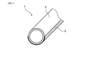
- the electric wire protection member 1 includes a metal pipe 2 through which the electric wire 4 is inserted, and a resin layer 3 that covers the outer surface of the metal pipe 2.
- the resin layer 3 is made of a resin having a relaxation modulus of 10 GPa or less at a relaxation time of 10 ⁇ 3 s and a color tone different from the ground color of the metal pipe 2. Further, the thickness of the resin layer 3 is 30 ⁇ m or more.
- the electric wire protection member 1 of this example can be configured as a wire harness 10 by inserting an electric wire 4 therein as shown in FIG.
- the wire harness 10 can be suitably used for, for example, an application for connecting between a power conversion device and a battery or between a power conversion device and a motor in an electric vehicle or a hybrid vehicle.
- the metal pipe 2 of this example is a cylindrical straight pipe made of an aluminum alloy.
- the metal pipe 2 may be appropriately bent according to the wiring form of the wire harness 10.
- the half circumference on the outer surface of the metal pipe 2 is covered with a resin layer 3.
- a resin layer 3 is formed, for example, by applying a resin paint only to the half circumference on the outer surface of the metal pipe 2 and then drying the resin paint to form a resin coating film, or forming a resin coating on the outer circumference of the metal pipe 2. It can be formed by a method such as affixing a resin sheet only.
- the resin coating can be applied by a known method such as brush coating, spray coating, or dipping.
- the resin layer 3 in this example is colored orange. Thereby, in the state where electric wire protection member 1 was attached to vehicle V, it can be visually recognized that the high voltage electric wire is inserted in the inside.
- the relaxation elastic modulus of the resin constituting the resin layer 3 can be measured, for example, by the following method. First, a part of the resin layer 3 is peeled off from the wire protection member 1 and a measurement piece is collected. Using this test piece, dynamic viscoelasticity measurement is performed at various measurement temperatures to obtain a frequency f-storage elastic modulus E ′ curve at each measurement temperature. Then, these curves are synthesized using a time-temperature conversion rule to obtain a master curve. The frequency f axis of the obtained master curve is converted to the time t axis, and the storage elastic modulus E ′ is defined as the relaxation elastic modulus. Based on the time t-relaxation modulus curve, the relaxation modulus at the relaxation time of 10 ⁇ 3 s is calculated.
- the electric wire protection member 1 has a metal pipe 2 and a resin layer 3 that covers the outer surface of the metal pipe 2. Moreover, the resin layer 3 is comprised from resin whose relaxation elastic modulus in relaxation time 10 ⁇ -3> s is 10 GPa or less. Since such a resin has a relaxation elastic modulus in the above specific range, for example, as shown in FIG. 2, it is possible to effectively relieve the impact when the pebbles s collide. Therefore, the resin layer 3 can reduce damage due to chipping.
- the thickness of the resin layer 3 is 30 ⁇ m or more, it is possible to prevent the scratch from reaching the metal pipe 2 when the resin layer 3 is damaged by chipping.
- the electric wire protection member 1 has the resin layer 3 that is not easily damaged during chipping and that can prevent the metal pipe 2 from being damaged. Therefore, the wire protection member 1 can reduce damage to the metal pipe 2 due to chipping.
- the resin layer 3 has a thickness in the above specific range and is made of an orange resin. Therefore, it can be easily recognized that the resin layer 3 is formed on the outer surface of the metal pipe 2. As a result, the electric wire protection member 1 can easily visually recognize that the high-voltage electric wire is inserted through the electric wire protection member 1.
- the electric wire protection member 1 of this example is attached to the vehicle V so that the resin layer 3 faces the road surface side, thereby causing a collision with the metal pipe 2 such as pebbles s jumping off the road surface. It can be further reduced. As a result, damage to the metal pipe 2 can be further reduced. Further, by attaching the wire protection member 1 to the vehicle V as shown in FIG. 2, the resin layer 3 can be easily visually recognized in the wiring work or the detaching work of the wire harness 10. Therefore, it can be easily recognized that the high-voltage electric wire is inserted into the electric wire protection member 1.
- the electric wire protection member 1 is covered with the resin layer 3 at least a half circumference and less than the whole circumference on the outer surface of the metal pipe 2. Therefore, the effect of reducing damage of the metal pipe 2 and high visibility can be obtained, and the amount of resin used for the resin layer 3 can be reduced. Thereby, the further cost reduction of the electric wire protection member 1 can be anticipated.
- the test body of this example has a cylindrical metal pipe 2 made of an aluminum alloy, and a resin layer 3 formed so as to cover a half circumference on the outer surface of the metal pipe 2.
- the resin layer 3 is composed of a resin coating film obtained by drying a resin paint. Specifically, the following four types of resin paints were used.
- the thickness of the resin layer 3 shown in Tables 1 to 4 is the thickness of the central portion of the resin layer 3 in the circumferential direction of the metal pipe 2 measured using an eddy current film thickness meter.
- the resin paints A to D used in this example are all colored orange.
- the relaxation elastic modulus of each resin layer 3 was measured by the method mentioned above using the dynamic viscoelasticity measuring apparatus.
- Specific measurement conditions for the storage elastic modulus E ′ were as follows. ⁇ Measurement frequency 0.01-100Hz Measurement temperature -40 ° C, -30 ° C, -20 ° C, -10 ° C, 0 ° C, 10 ° C, 20 ° C, 30 ° C, 40 ° C, 50 ° C, 60 ° C, 70 ° C, 80 ° C, 100 ° C ⁇ Measurement strain 1%
- Chipping resistance was performed by visual observation of the resin layer after the chipping test.
- the chipping test was carried out using a gravelometer by a method according to JASO M104 or SAE J400.
- the test conditions for the chipping test were as follows. ⁇ Injection air pressure: 0.392 MPa ⁇ Air flow rate: 50L / s -Impact object: No. 6 crushed stone (JIS A5001) -Total amount of impact used: 500g ⁇ Injection angle: 90 °
- specimens 1, 5 and 9 having a resin layer 3 made of a resin having a relaxation elastic modulus in the specific range and having a thickness of 30 ⁇ m or more are resistant to chipping. And excellent visibility. Therefore, by incorporating the wire protection member 1 having the above specific configuration into the wire harness 10, durability against chipping can be improved and a high-voltage wire is inserted into the wire protection member 1. It can be easily visually recognized.
- test bodies 13 to 16 having a relaxation elastic modulus of the resin exceeding 10 GPa at the relaxation time of 10 ⁇ 3 s the resin layer 3 was damaged after the chipping test, and the metal pipe 2 was exposed on the outer surface of the test body. Therefore, these specimens may cause pitting corrosion of the metal pipe 2 relatively early.
- Specimens 2-4, 6-8, and 14-16 in which the thickness of the resin layer 3 is less than 30 ⁇ m, are a result of visual observation, and a portion where the resin layer 3 is formed and a portion where the metal pipe 2 is exposed could not be identified, and the visibility was poor.
Landscapes
- Engineering & Computer Science (AREA)
- Architecture (AREA)
- Civil Engineering (AREA)
- Structural Engineering (AREA)
- Mechanical Engineering (AREA)
- Insulated Conductors (AREA)
- Details Of Indoor Wiring (AREA)
Abstract
高圧電線が挿通されていることを容易に視認でき、かつ、チッピングによる金属パイプの損傷を低減することができる電線保護部材(1)及び電線保護部材(1)を有するワイヤーハーネス(10)を提供する。電線保護部材(1)は、車両Vの床下に配置される電線(4)を保護するために用いられる。電線保護部材(1)は、電線(4)が挿通される金属パイプ(2)と、金属パイプ(2)の外表面を覆う樹脂層(3)とを有している。樹脂層(3)は、緩和時間10-3sにおける緩和弾性率が10GPa以下であるとともに金属パイプ(2)の地色とは異なる色調を有する樹脂から構成されている。また、樹脂層(3)の厚さは30μm以上である。
Description
本発明は、電線保護部材及び電線保護部材を有するワイヤーハーネスに関する。
自動車等の車両の床下に配索されるワイヤーハーネスは、電線と、電線を保護するための電線保護部材とを有している。電線保護部材には、例えば、バッテリーとエンジンとを接続する電線等の高圧電線が挿通されることがある。
この種の電線保護部材は、アルミニウム製のパイプから構成されていることが多い。また、電線保護部材の表面は、ワイヤーハーネスの配索作業や取り外し作業等の際に高圧電線が挿通されていることを視認できるように、特定の色に着色されている。例えば、特許文献1には、押出成形等の方法により、特定の色に着色された樹脂識別部をパイプの表面の全周に亘って形成する技術が記載されている。また、特許文献2及び特許文献3には、パイプ本体の外表面の一部に、塗料やテープ等の着色剤を用いて識別マークを形成する技術が記載されている。
しかし、特許文献1の電線保護部材は、路面から飛び跳ねた小石等が電線保護部材に衝突することにより樹脂識別部が損傷を受ける、いわゆるチッピングが発生するおそれがある。チッピングにより樹脂識別部が損傷を受けると、場合によってはその傷がパイプまで到達することがある。この傷に塩化物イオンを含む水などの腐食性を有する物質が付着した場合、パイプの孔食が起こるおそれがあり、更にはパイプの破損を招くおそれがある。
また、特許文献2及び3の電線保護部材は、パイプの外表面に、識別マークにより覆われていない部分を有している。そのため、路面から飛び跳ねた小石等によりパイプに傷がつき易いという問題がある。
本発明は、かかる背景に鑑みてなされたものであり、高圧電線が挿通されていることを容易に視認でき、かつ、チッピングによる金属パイプの損傷を低減することができる電線保護部材及び該電線保護部材を有するワイヤーハーネスを提供しようとするものである。
本発明の一態様は、車両の床下に配置される電線保護部材であって、
電線を挿通する金属パイプと、
該金属パイプの外表面を覆う樹脂層とを有し、
該樹脂層は、
緩和時間10-3sにおける緩和弾性率が10GPa以下であるとともに上記金属パイプの地色とは異なる色調を有する樹脂から構成されており、
厚さが30μm以上である、電線保護部材にある。
電線を挿通する金属パイプと、
該金属パイプの外表面を覆う樹脂層とを有し、
該樹脂層は、
緩和時間10-3sにおける緩和弾性率が10GPa以下であるとともに上記金属パイプの地色とは異なる色調を有する樹脂から構成されており、
厚さが30μm以上である、電線保護部材にある。
本発明の他の態様は、上記の態様の電線保護部材と、
該電線保護部材の上記金属パイプ内に挿通された電線とを有する、ワイヤーハーネスにある。
該電線保護部材の上記金属パイプ内に挿通された電線とを有する、ワイヤーハーネスにある。
上記電線保護部材は、金属パイプと、該金属パイプの外表面を覆う樹脂層とを有している。また、該樹脂層は、緩和時間10-3sにおける緩和弾性率が10GPa以下である樹脂から構成されている。上記特定の範囲の緩和弾性率を有する上記樹脂は、小石等が衝突した際の衝撃を効果的に緩和することができる。それ故、上記樹脂層は、チッピングによる損傷を低減することができる。
また、上記樹脂層は、その厚さが30μm以上であるため、チッピングにより上記樹脂層が損傷を受けた際に、その傷が上記金属パイプまで到達することを抑制できる。
このように、上記電線保護部材は、チッピングによる損傷を受けにくく、かつ、上記金属パイプまで傷が到達することを抑制できる上記樹脂層を有している。そのため、上記電線保護部材は、チッピングによる金属パイプの損傷を低減することができる。
また、上記樹脂層は、上記特定の範囲の厚さを有しているとともに、上記金属パイプの地色とは異なる色調を有する樹脂から構成されている。それ故、上記金属パイプの外表面に上記樹脂層が形成されていることを容易に視認することができる。その結果、上記電線保護部材は、その内部に高圧電線が挿通されていることを容易に視認することができる。
上記ワイヤーハーネスは、上記の態様の電線保護部材と、該電線保護部材の上記金属パイプ内に挿通された電線とを有している。上記ワイヤーハーネスは、上記電線保護部材が車両の床下に配置されるようにして配索することにより、チッピングによる上記電線保護部材の破損を長期間に亘って抑制することができる。
上記電線保護部材において、金属パイプは、ワイヤーハーネスの軽量化の観点から、通常、アルミニウムまたはアルミニウム合金から構成されている。
金属パイプの外表面を覆う樹脂層は、具体的には、樹脂塗膜や樹脂シート等の種々の態様をとることができる。樹脂塗膜は、例えば、エポキシ樹脂塗料、ポリエステル樹脂塗料、(メタ)アクリレート樹脂塗料、ポリアミド樹脂塗料あるいはシリコーン樹脂塗料等の種々の塗料を金属パイプの外表面に塗布した後、塗料を硬化または乾燥させることにより形成することができる。樹脂塗膜は、ポリエステル樹脂または(メタ)アクリレート樹脂から構成されていることが好ましい。この場合には、樹脂層の耐熱性をより高くすることができるとともに、樹脂層をより剥離しにくくすることができる。
また、樹脂シートは、例えば、接着剤を用いてポリエチレン樹脂、ポリエステル樹脂または塩化ビニル樹脂等のシートを金属パイプの外表面に貼付することにより形成できる。樹脂シートは、ポリエステル樹脂から構成されていることが好ましい。この場合には、樹脂層の耐熱性をより高くすることができる。また、樹脂層は、金属パイプの外表面に熱可塑性樹脂を押出成形することにより形成することもできる。
上記樹脂層の厚さは30μm以上とする。樹脂層の厚さを30μm以上とすることにより、上記電線保護部材の表面を、金属パイプの地色とは異なる、例えばオレンジ色等の色調に着色することができる。その結果、例えば、ワイヤーハーネスの配索作業や取り外し作業等において、上記電線保護部材内に高圧電線が挿通されていることを容易に視認することができる。また、この場合には、チッピングにより樹脂層が損傷を受けた場合に、その傷が金属パイプまで到達することを抑制することができる。耐チッピング性及び視認性の観点からは、樹脂層の厚さを35μm以上とすることが好ましく、40μm以上とすることがより好ましく、50μm以上とすることがさらに好ましい。
樹脂層の厚さが30μm未満の場合には、金属パイプの地色が透けやすくなるため、電線保護部材の外表面に上記樹脂層が設けられている状態と、金属パイプが露出している状態とを外観から判別することが難しくなるおそれがある。そのため、この場合には、ワイヤーハーネスの配索作業等の際に、電線保護部材内に高圧電線が挿通されていることを視認しにくくなるおそれがある。
耐チッピング性及び視認性の観点からは、樹脂層の厚さが厚い方が好ましい。しかし、樹脂層の厚さが過度に厚くなると、樹脂の使用量が多くなり、コストアップを招くおそれがある。樹脂の使用量を低減する観点からは、樹脂層の厚さを100μm以下とすることが好ましく、95μm以下とすることがより好ましく、80μm以下とすることがさらに好ましい。
樹脂層は、緩和時間10-3sにおける緩和弾性率が10GPa以下であるとともに、上記金属パイプの地色とは異なる色調を有する樹脂から構成されている。緩和時間10-3sにおける緩和弾性率が10GPa以下である樹脂は、小石等が衝突した際の衝撃を効果的に緩和することができる。それ故、樹脂層に上記特定の範囲の緩和弾性率を有する樹脂を用いることにより、チッピングによる樹脂層の損傷を低減することができる。一方、緩和時間10-3sにおける樹脂の緩和弾性率が10GPaを超える場合には、チッピングにより樹脂層が破損し易くなり、ひいては金属パイプが損傷を受け易くなる。
これは、小石等が樹脂層に衝突してから跳ね返るまでの時間が10-3s程度であるためと考えられる。即ち、緩和時間10-3sにおける樹脂の緩和弾性率が低い場合には、小石等が樹脂層に衝突した際に、樹脂層が比較的容易に変形すると推測される。この樹脂層の変形により、小石等が衝突した際に樹脂層に加わる衝撃を効果的に緩和することができると考えられる。一方、緩和時間10-3sにおける樹脂の緩和弾性率が過度に高い場合には、小石等が衝突した際に樹脂層の変形が起こりにくいため、樹脂層に加わる衝撃が緩和されにくいと考えられる。
金属パイプは、その外表面における半周以上を樹脂層により覆われていることが好ましい。この場合には、ワイヤーハーネスを車両に配索する際に、樹脂層が路面側を向くようにして上記電線保護部材を車両に取り付けることができる。これにより、路面から飛び跳ねた小石等が樹脂層に衝突し易くなるため、小石等の金属パイプへの衝突をより低減することができる。その結果、金属パイプの損傷をより低減することができる。また、上記樹脂層が路面側を向くようにして電線保護部材を取り付けることにより、ワイヤーハーネスの配索作業や取り外し作業等において、樹脂層を容易に視認することができる。それ故、この場合には、電線保護部材内に高圧電線が挿通されていることを容易に視認することができる。
樹脂層に使用する樹脂の量を低減する観点からは、金属パイプの外表面における半周以上全周未満が上記樹脂層により覆われていることがより好ましい。この場合には、上述した金属パイプの損傷を低減する効果及び高い視認性を得ることができるとともに、樹脂層の形成に使用する樹脂の量を低減することができる。これにより、電線保護部材の一層のコストダウンを期待することができる。
ワイヤーハーネスは、上記電線保護部材と、電線保護部材内に挿通された電線とを有している。ワイヤーハーネスは、1個の電線保護部材を有していてもよく、複数個の電線保護部材を有していてもよい。ワイヤーハーネスが複数個の電線保護部材を有している場合には、上記樹脂層を有する電線保護部材が車両の床下に配置されるように構成されていれば、上述した金属パイプの損傷を低減する効果等を奏することができる。
また、電線保護部材内に挿通される電線の本数は特に限定されることは無く、用途に応じて1本あるいは複数本の電線を電線保護部材内に挿通することができる。
上記の構成を有するワイヤーハーネスは、例えば電気自動車やハイブリッド自動車における、電力変換装置とバッテリーとの間、あるいは電力変換装置とモータとの間等を接続する用途に好適に用いることができる。
(実施例)
上記電線保護部材の実施例について、図を用いて説明する。図2に示すように、電線保護部材1は、車両Vの床下に配置される電線4を保護するために用いられる。図1に示すように、電線保護部材1は、電線4が挿通される金属パイプ2と、金属パイプ2の外表面を覆う樹脂層3とを有している。樹脂層3は、緩和時間10-3sにおける緩和弾性率が10GPa以下であるとともに金属パイプ2の地色とは異なる色調を有する樹脂から構成されている。また、樹脂層3の厚さは30μm以上である。
上記電線保護部材の実施例について、図を用いて説明する。図2に示すように、電線保護部材1は、車両Vの床下に配置される電線4を保護するために用いられる。図1に示すように、電線保護部材1は、電線4が挿通される金属パイプ2と、金属パイプ2の外表面を覆う樹脂層3とを有している。樹脂層3は、緩和時間10-3sにおける緩和弾性率が10GPa以下であるとともに金属パイプ2の地色とは異なる色調を有する樹脂から構成されている。また、樹脂層3の厚さは30μm以上である。
本例の電線保護部材1は、例えば図2に示すように、内部に電線4を挿通することにより、ワイヤーハーネス10として構成することができる。ワイヤーハーネス10は、例えば電気自動車やハイブリッド自動車における、電力変換装置とバッテリーとの間、あるいは電力変換装置とモータとの間等を接続する用途に好適に用いることができる。
図1に示すように、本例の金属パイプ2はアルミニウム合金からなる円筒状の直管である。なお、金属パイプ2は、ワイヤーハーネス10の配索形態に応じて適宜屈曲されていてもよい。
図1及び図2に示すように、金属パイプ2の外表面における半周は、樹脂層3により覆われている。このような樹脂層3は、例えば、金属パイプ2の外表面における半周のみに樹脂塗料を塗布した後、樹脂塗料を乾燥させて樹脂塗膜を形成する、あるいは、金属パイプ2の外表面における半周のみに樹脂シートを貼付する等の方法により形成することができる。なお、樹脂塗料の塗布は、刷毛塗りやスプレー塗布、浸漬などの公知の方法により行うことができる。
本例の樹脂層3は、オレンジ色に着色されている。これにより、電線保護部材1が車両Vに取り付けられた状態において、その内部に高圧電線が挿通されていることを視認することができる。
樹脂層3を構成する樹脂の緩和弾性率は、例えば、以下の方法により測定することができる。まず、電線保護部材1から樹脂層3の一部を剥ぎ取り、測定片を採取する。この試験片を用いて種々の測定温度で動的粘弾性測定を行い、各測定温度における周波数f-貯蔵弾性率E’曲線を得る。次いで、時間-温度換算則を用いてこれらの曲線を合成し、マスターカーブを得る。得られたマスターカーブの周波数f軸を時間t軸に変換し、貯蔵弾性率E’を緩和弾性率とする。この時間t-緩和弾性率曲線に基づき、緩和時間10-3sにおける緩和弾性率を算出する。
次に、電線保護部材1の作用効果について説明する。電線保護部材1は、金属パイプ2と、金属パイプ2の外表面を覆う樹脂層3とを有している。また、樹脂層3は、緩和時間10-3sにおける緩和弾性率が10GPa以下である樹脂から構成されている。このような樹脂は、上記特定の範囲の緩和弾性率を有しているため、例えば図2に示すように、小石s等が衝突した際の衝撃を効果的に緩和することができる。それ故、樹脂層3は、チッピングによる損傷を低減することができる。
また、樹脂層3は、その厚さが30μm以上であるため、チッピングにより樹脂層3が損傷を受けた際に、その傷が金属パイプ2まで到達することを抑制できる。
このように、電線保護部材1は、チッピングの際に損傷を受けにくく、かつ、金属パイプ2まで傷が到達することを抑制できる樹脂層3を有している。そのため、電線保護部材1は、チッピングによる金属パイプ2の損傷を低減することができる。
また、樹脂層3は、上記特定の範囲の厚さを有しているとともに、オレンジ色を呈する樹脂から構成されている。それ故、金属パイプ2の外表面に樹脂層3が形成されていることを容易に視認することができる。その結果、電線保護部材1は、その内部に高圧電線が挿通されていることを容易に視認することができる。
本例の電線保護部材1は、例えば図2に示すように、樹脂層3が路面側を向くようにして車両Vに取り付けることにより、路面から飛び跳ねた小石s等の金属パイプ2への衝突をより低減することができる。その結果、金属パイプ2の損傷をより低減することができる。また、図2に示すように電線保護部材1を車両Vに取り付けることにより、ワイヤーハーネス10の配索作業や取り外し作業等において、樹脂層3を容易に視認することができる。それ故、電線保護部材1内に高圧電線が挿通されていることを容易に視認することができる。
また、電線保護部材1は、金属パイプ2の外表面における半周以上全周未満が樹脂層3により覆われている。そのため、上述した金属パイプ2の損傷を低減する効果及び高い視認性を得ることができるとともに、樹脂層3に使用する樹脂の量を低減することができる。これにより、電線保護部材1の一層のコストダウンを期待することができる。
(実験例)
本例は、緩和時間10-3sにおける樹脂の緩和弾性率及び樹脂層3の厚さを種々変更した電線保護部材1の耐チッピング性及び視認性を評価した例である。本例においては、表1~表4に示すように、樹脂層3を種々変更した試験体1~16を作製した。そして、これらの試験体を用いてチッピング試験及び視認性の評価を行った。
本例は、緩和時間10-3sにおける樹脂の緩和弾性率及び樹脂層3の厚さを種々変更した電線保護部材1の耐チッピング性及び視認性を評価した例である。本例においては、表1~表4に示すように、樹脂層3を種々変更した試験体1~16を作製した。そして、これらの試験体を用いてチッピング試験及び視認性の評価を行った。
<試験体>
本例の試験体は、アルミニウム合金からなる円筒状の金属パイプ2と、金属パイプ2の外表面における半周を覆うように形成した樹脂層3とを有している。樹脂層3は、樹脂塗料を乾燥させてなる樹脂塗膜から構成されている。樹脂塗料としては、具体的には以下の4種を用いた。
本例の試験体は、アルミニウム合金からなる円筒状の金属パイプ2と、金属パイプ2の外表面における半周を覆うように形成した樹脂層3とを有している。樹脂層3は、樹脂塗料を乾燥させてなる樹脂塗膜から構成されている。樹脂塗料としては、具体的には以下の4種を用いた。
・樹脂塗料A:株式会社スリーボンド製「TB3017F」
(緩和時間10-3sにおける緩和弾性率 8GPa)
・樹脂塗料B:株式会社スリーボンド製「TB3013Q」
(緩和時間10-3sにおける緩和弾性率 9GPa)
・樹脂塗料C:株式会社スリーボンド製「TB3006D」
(緩和時間10-3sにおける緩和弾性率 10GPa)
・樹脂塗料D:株式会社スリーボンド製「TB3057」
(緩和時間10-3sにおける緩和弾性率 11GPa)
(緩和時間10-3sにおける緩和弾性率 8GPa)
・樹脂塗料B:株式会社スリーボンド製「TB3013Q」
(緩和時間10-3sにおける緩和弾性率 9GPa)
・樹脂塗料C:株式会社スリーボンド製「TB3006D」
(緩和時間10-3sにおける緩和弾性率 10GPa)
・樹脂塗料D:株式会社スリーボンド製「TB3057」
(緩和時間10-3sにおける緩和弾性率 11GPa)
なお、表1~表4に示した樹脂層3の厚みは、渦電流式膜厚計を用いて測定した、金属パイプ2の周方向における樹脂層3の中央部の厚みである。また、本例において使用した樹脂塗料A~Dは、全てオレンジ色に着色されている。
また、各樹脂層3の緩和弾性率は、動的粘弾性測定装置を用い、上述した方法により測定した。貯蔵弾性率E’の具体的な測定条件は、以下の通りとした。
・測定周波数 0.01~100Hz
・測定温度 -40℃、-30℃、-20℃、-10℃、0℃、10℃、20℃、30℃、40℃、50℃、60℃、70℃、80℃、100℃
・測定ひずみ 1%
・測定周波数 0.01~100Hz
・測定温度 -40℃、-30℃、-20℃、-10℃、0℃、10℃、20℃、30℃、40℃、50℃、60℃、70℃、80℃、100℃
・測定ひずみ 1%
<耐チッピング性>
耐チッピング性の評価は、チッピング試験後の樹脂層の目視観察により行った。チッピング試験は、グラベロメータを用い、JASO M104またはSAE J400の規定に準じた方法により実施した。チッピング試験の試験条件は以下の通りとした。
・射出用空気圧:0.392MPa
・エアー流量:50L/s
・衝撃物:6号砕石(JIS A5001)
・衝撃物の使用総量:500g
・射出角度:90°
耐チッピング性の評価は、チッピング試験後の樹脂層の目視観察により行った。チッピング試験は、グラベロメータを用い、JASO M104またはSAE J400の規定に準じた方法により実施した。チッピング試験の試験条件は以下の通りとした。
・射出用空気圧:0.392MPa
・エアー流量:50L/s
・衝撃物:6号砕石(JIS A5001)
・衝撃物の使用総量:500g
・射出角度:90°
上記の条件により樹脂層3に衝撃物を衝突させた後、樹脂層3の外観を目視観察した。その結果、樹脂層3に損傷が無い、または樹脂層3の損傷が金属パイプ2まで到達していない場合には、表1~表4の「耐チッピング性」の欄に「A」の記号を記載した。一方、目視観察の結果、樹脂層3の損傷が金属パイプ2まで到達し、金属パイプ2が外表面に露出している場合には、表1~表4の「耐チッピング性」の欄に「B」の記号を記載した。
<視認性>
視認性の評価は、チッピング試験を行う前の試験体の目視観察により行った。目視観察の結果、樹脂層3が形成された部分と金属パイプ2が露出している部分とが判別できた場合には、表1~表4の「視認性」の欄に「A」の記号を記載した。一方、目視観察の結果、樹脂層3が形成された部分と金属パイプ2が露出している部分とが判別できなかった場合には、表1~表4の「視認性」の欄に「B」の記号を記載した。
視認性の評価は、チッピング試験を行う前の試験体の目視観察により行った。目視観察の結果、樹脂層3が形成された部分と金属パイプ2が露出している部分とが判別できた場合には、表1~表4の「視認性」の欄に「A」の記号を記載した。一方、目視観察の結果、樹脂層3が形成された部分と金属パイプ2が露出している部分とが判別できなかった場合には、表1~表4の「視認性」の欄に「B」の記号を記載した。

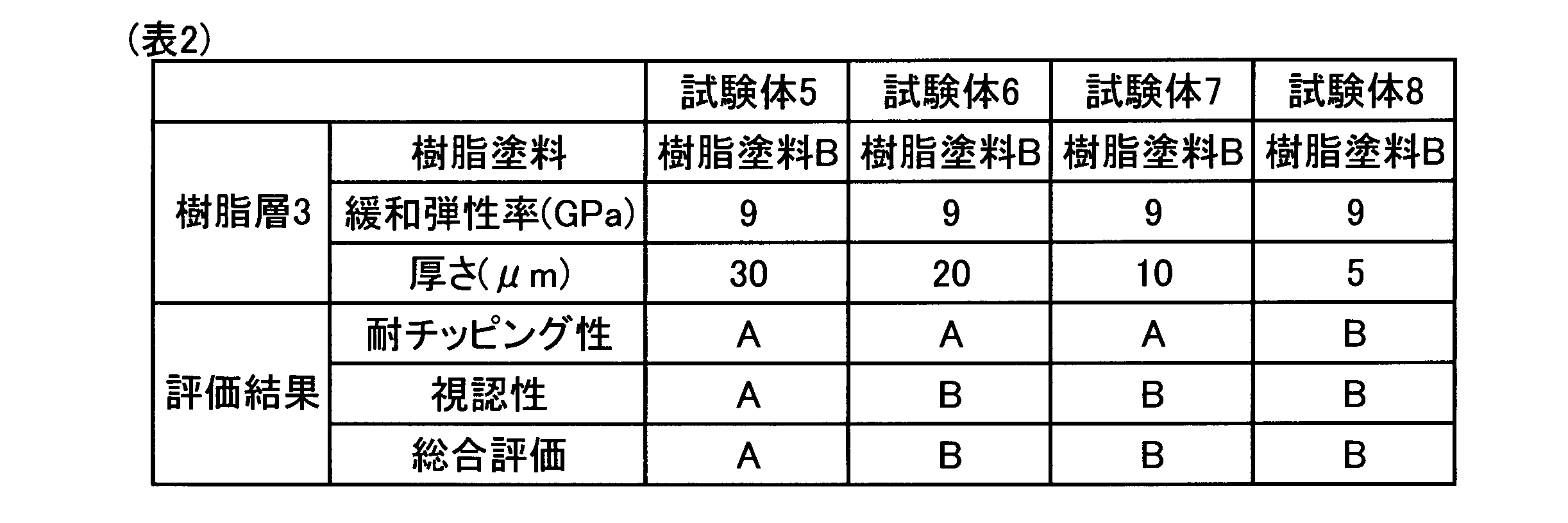

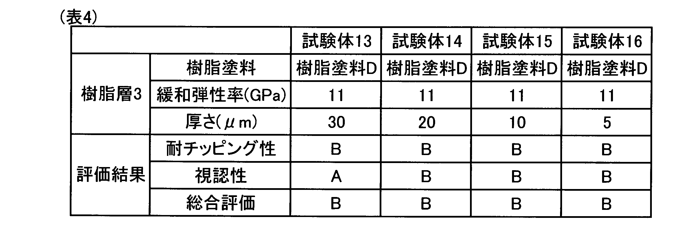
表1~表4に示したように、上記特定の範囲の緩和弾性率を有する樹脂から構成され、厚さが30μm以上である樹脂層3を有する試験体1、5及び9は、耐チッピング性及び視認性の両方に優れている。それ故、上記特定の構成を有する電線保護部材1をワイヤーハーネス10に組み込むことにより、チッピングに対する耐久性を向上させることができるとともに、電線保護部材1の内部に高圧電線が挿通されていることを容易に視認することができる。
緩和時間10-3sにおける樹脂の緩和弾性率が10GPaを超える試験体13~16は、チッピング試験後に樹脂層3が損傷を受け、金属パイプ2が試験体の外表面に露出した。それ故、これらの試験体は、金属パイプ2の孔食が比較的早期に起こるおそれがある。
樹脂層3の厚さが30μm未満である試験体2~4、6~8及び14~16は、目視観察の結果、樹脂層3が形成された部分と金属パイプ2が露出している部分とが判別できず、視認性に劣っていた。
なお、上述した実施例及び実験例においては、金属パイプ2の外表面における半周が樹脂層3により覆われた電線保護部材1の例を示したが、金属パイプ2の外表面における半周が樹脂層3により覆われていてもよい。その他、本発明は上記の態様に限定されるものではなく、その趣旨を損なわない範囲で適宜構成を変更することができる。
Claims (3)
- 車両の床下に配置される電線を保護するための電線保護部材であって、
電線が挿通される金属パイプと、
該金属パイプの外表面を覆う樹脂層とを有し、
該樹脂層は、
緩和時間10-3sにおける緩和弾性率が10GPa以下であるとともに上記金属パイプの地色とは異なる色調を有する樹脂から構成されており、
厚さが30μm以上である、電線保護部材。 - 上記金属パイプの外表面における半周以上が上記樹脂層により覆われている、請求項1に記載の電線保護部材。
- 請求項1または2に記載された電線保護部材と、
該電線保護部材の上記金属パイプ内に挿通された電線とを有する、ワイヤーハーネス。
Applications Claiming Priority (2)
| Application Number | Priority Date | Filing Date | Title |
|---|---|---|---|
| JP2015235817A JP6536385B2 (ja) | 2015-12-02 | 2015-12-02 | 電線保護部材及びワイヤーハーネス |
| JP2015-235817 | 2015-12-02 |
Publications (1)
| Publication Number | Publication Date |
|---|---|
| WO2017094533A1 true WO2017094533A1 (ja) | 2017-06-08 |
Family
ID=58797168
Family Applications (1)
| Application Number | Title | Priority Date | Filing Date |
|---|---|---|---|
| PCT/JP2016/084311 Ceased WO2017094533A1 (ja) | 2015-12-02 | 2016-11-18 | 電線保護部材及びワイヤーハーネス |
Country Status (2)
| Country | Link |
|---|---|
| JP (1) | JP6536385B2 (ja) |
| WO (1) | WO2017094533A1 (ja) |
Families Citing this family (1)
| Publication number | Priority date | Publication date | Assignee | Title |
|---|---|---|---|---|
| JP6855966B2 (ja) | 2017-07-19 | 2021-04-07 | 住友電装株式会社 | ワイヤハーネス |
Citations (2)
| Publication number | Priority date | Publication date | Assignee | Title |
|---|---|---|---|---|
| JP2001146575A (ja) * | 1999-11-19 | 2001-05-29 | Kansai Paint Co Ltd | 耐チッピング性塗料組成物 |
| WO2014061795A1 (ja) * | 2012-10-18 | 2014-04-24 | 矢崎総業株式会社 | ワイヤハーネス用外装部材及びワイヤハーネス |
-
2015
- 2015-12-02 JP JP2015235817A patent/JP6536385B2/ja active Active
-
2016
- 2016-11-18 WO PCT/JP2016/084311 patent/WO2017094533A1/ja not_active Ceased
Patent Citations (2)
| Publication number | Priority date | Publication date | Assignee | Title |
|---|---|---|---|---|
| JP2001146575A (ja) * | 1999-11-19 | 2001-05-29 | Kansai Paint Co Ltd | 耐チッピング性塗料組成物 |
| WO2014061795A1 (ja) * | 2012-10-18 | 2014-04-24 | 矢崎総業株式会社 | ワイヤハーネス用外装部材及びワイヤハーネス |
Also Published As
| Publication number | Publication date |
|---|---|
| JP2017103931A (ja) | 2017-06-08 |
| JP6536385B2 (ja) | 2019-07-03 |
Similar Documents
| Publication | Publication Date | Title |
|---|---|---|
| JP5123991B2 (ja) | 防食剤、端子付き被覆電線およびワイヤーハーネス | |
| JP6172127B2 (ja) | ワイヤーハーネス | |
| US9640300B2 (en) | Cable having a thin film material and methods of preventing discoloration damage to a cable having a thin film material | |
| US9676350B2 (en) | Shielded pipe having fixed and bendable portions | |
| RU2016152472A (ru) | Композиция для покрытия с антикоррозийным эффектом | |
| MX2020011357A (es) | Sistemas, métodos e interfaces para la generación rápida de recubrimientos. | |
| US20180173830A1 (en) | Vehicle body composite coating and design method thereof | |
| WO2017094533A1 (ja) | 電線保護部材及びワイヤーハーネス | |
| JP5077960B2 (ja) | 屋外鋼構造物の塗膜形成方法 | |
| JP3228265B2 (ja) | 防錆被覆pc鋼より線の製造方法 | |
| JP6443321B2 (ja) | 電線保護部材及びワイヤーハーネス | |
| JP7480893B2 (ja) | ワイヤーハーネス | |
| JP6399056B2 (ja) | ポリエチレン被覆鋼管およびその製造方法 | |
| JP2003193622A (ja) | 樹脂被覆防食pc鋼材 | |
| JP6167952B2 (ja) | 端子付き被覆電線およびワイヤーハーネス | |
| JP6040924B2 (ja) | 端子付き被覆電線およびワイヤーハーネス | |
| WO2017145785A1 (ja) | 電線保護部材及びその製造方法並びにワイヤーハーネス | |
| JP2018170160A (ja) | 端子付き電線およびワイヤハーネス | |
| JP2013025931A (ja) | 防食剤、端子付き被覆電線およびワイヤーハーネス | |
| JP6610685B2 (ja) | ポリエチレン被覆鋼管およびその製造方法 | |
| CN107868523B (zh) | 船舶外船体保护涂层及其使用方法 | |
| CN207664565U (zh) | 屏蔽分线器 | |
| JP6607265B2 (ja) | ポリエチレン被覆鋼管およびその製造方法 | |
| Avakov et al. | Analysis of methods of assessing the quality of protective paint car coatings | |
| US9864112B1 (en) | Conformable retroreflective graphic film |
Legal Events
| Date | Code | Title | Description |
|---|---|---|---|
| 121 | Ep: the epo has been informed by wipo that ep was designated in this application |
Ref document number: 16870471 Country of ref document: EP Kind code of ref document: A1 |
|
| NENP | Non-entry into the national phase |
Ref country code: DE |
|
| 122 | Ep: pct application non-entry in european phase |
Ref document number: 16870471 Country of ref document: EP Kind code of ref document: A1 |