WO2017094150A1 - ボイラの蒸気流量制御方法及び焼却炉システム - Google Patents
ボイラの蒸気流量制御方法及び焼却炉システム Download PDFInfo
- Publication number
- WO2017094150A1 WO2017094150A1 PCT/JP2015/083923 JP2015083923W WO2017094150A1 WO 2017094150 A1 WO2017094150 A1 WO 2017094150A1 JP 2015083923 W JP2015083923 W JP 2015083923W WO 2017094150 A1 WO2017094150 A1 WO 2017094150A1
- Authority
- WO
- WIPO (PCT)
- Prior art keywords
- flow rate
- steam flow
- exhaust gas
- supply flow
- combustion air
- Prior art date
- Legal status (The legal status is an assumption and is not a legal conclusion. Google has not performed a legal analysis and makes no representation as to the accuracy of the status listed.)
- Ceased
Links
Images


Classifications
-
- F—MECHANICAL ENGINEERING; LIGHTING; HEATING; WEAPONS; BLASTING
- F22—STEAM GENERATION
- F22B—METHODS OF STEAM GENERATION; STEAM BOILERS
- F22B35/00—Control systems for steam boilers
-
- F—MECHANICAL ENGINEERING; LIGHTING; HEATING; WEAPONS; BLASTING
- F23—COMBUSTION APPARATUS; COMBUSTION PROCESSES
- F23G—CREMATION FURNACES; CONSUMING WASTE PRODUCTS BY COMBUSTION
- F23G5/00—Incineration of waste; Incinerator constructions; Details, accessories or control therefor
- F23G5/44—Details; Accessories
- F23G5/46—Recuperation of heat
-
- F—MECHANICAL ENGINEERING; LIGHTING; HEATING; WEAPONS; BLASTING
- F23—COMBUSTION APPARATUS; COMBUSTION PROCESSES
- F23G—CREMATION FURNACES; CONSUMING WASTE PRODUCTS BY COMBUSTION
- F23G5/00—Incineration of waste; Incinerator constructions; Details, accessories or control therefor
- F23G5/50—Control or safety arrangements
-
- Y—GENERAL TAGGING OF NEW TECHNOLOGICAL DEVELOPMENTS; GENERAL TAGGING OF CROSS-SECTIONAL TECHNOLOGIES SPANNING OVER SEVERAL SECTIONS OF THE IPC; TECHNICAL SUBJECTS COVERED BY FORMER USPC CROSS-REFERENCE ART COLLECTIONS [XRACs] AND DIGESTS
- Y02—TECHNOLOGIES OR APPLICATIONS FOR MITIGATION OR ADAPTATION AGAINST CLIMATE CHANGE
- Y02P—CLIMATE CHANGE MITIGATION TECHNOLOGIES IN THE PRODUCTION OR PROCESSING OF GOODS
- Y02P80/00—Climate change mitigation technologies for sector-wide applications
- Y02P80/10—Efficient use of energy, e.g. using compressed air or pressurized fluid as energy carrier
- Y02P80/15—On-site combined power, heat or cool generation or distribution, e.g. combined heat and power [CHP] supply
Definitions
- the present invention relates to control of the flow rate of steam generated from a waste heat recovery boiler in an incinerator system for waste such as general waste and industrial waste, and in particular, nitrogen oxides (hereinafter referred to as “ The present invention relates to a steam flow control method for a boiler and an incinerator system that can reduce the amount of emissions of NOx).
- Waste incineration power generation using steam generated by incineration heat of general waste and the like is performed.
- general waste and the like are a mixture of a wide variety of substances, and thus the combustion state is not stable. Since the combustion state of general waste or the like is not stable, the amount of heat input to the boiler provided on the downstream side of the incinerator becomes unstable, and the generated steam flow from the boiler becomes unstable.
- Control of the flow rate of steam generated from a boiler in an incinerator system for general waste is normally performed by changing the flow rate of combustion air supplied to the combustion chamber in the incineration. For example, when the generated steam flow rate decreases, the generated steam flow rate can be recovered by increasing the supply flow rate of combustion air to the combustion chamber and advancing the combustion of general waste.
- the supply of combustion air causes the amount of oxygen in the combustion chamber to become excessive globally or locally, and oxygen reacts with nitrogen contained in general wastes or air. It is known that the amount of NOx generated increases.
- a method in which a reburning zone is provided above the combustion chamber and natural gas is supplied to the reburning zone to reduce NOx. ing.
- the supply flow rate of natural gas to the reburning zone together with the supply flow rate of combustion air to the combustion chamber
- the supply flow rate of the natural gas to the reburning zone is decreased together with the supply flow rate of the combustion air to the combustion chamber (for example, Patent Document 1). Etc.) has been made.
- the amount of natural gas required in the reburning method is an amount equivalent to about 10 percent of the amount of heat such as general waste.
- An object of the present invention is to provide a steam flow control method for a boiler and an incinerator system that can be used.
- the steam flow control method of the boiler for controlling the generated steam flow from the boiler provided in the incinerator by supplying combustion air and exhaust gas recirculation gas to the combustion chamber in the incinerator of the present invention Detect the generated steam flow, Calculate the operating steam flow rate from the generated steam flow rate and the preset target steam flow rate, Calculate the combustion air supply flow rate to the combustion chamber based on the operating steam flow rate, Supplying combustion air to the combustion chamber at the combustion air supply flow rate; Calculate the reference exhaust gas recirculation gas supply flow rate to the combustion chamber based on the incinerator temperature and outlet exhaust gas flow rate, Calculate the exhaust gas recirculation gas supply flow rate to the combustion chamber based on the operating steam flow rate and the reference exhaust gas recirculation gas supply flow rate, The exhaust gas recirculation gas is supplied to the combustion chamber at an exhaust gas recirculation gas supply flow rate.
- the combustion air supply flow rate can be calculated based on the exhaust gas recirculation gas supply flow rate in addition to the operation steam flow rate.
- the combustion air supply flow rate can be calculated based on the exhaust gas recirculation gas supply flow rate in addition to the operation steam flow rate.
- the operation steam flow can be calculated by PID control.
- the waste incineration equipment includes a combustion chamber, a combustion air supply device for supplying combustion air to the combustion chamber, and an exhaust gas recirculation An exhaust gas recirculation gas supply device for supplying gas to the combustion chamber, wherein the boiler equipment is a boiler, a generated steam flow detection device for detecting a generated steam flow rate from the boiler, and a steam flow control device for controlling the steam flow rate
- the steam flow control device includes a generated steam flow input device that receives the generated steam flow information from the generated steam flow detection device, and an operation steam flow from a preset target steam flow and generated steam flow.
- An operating steam flow rate calculating unit to calculate, a combustion air supply flow rate calculating unit to calculate a combustion air supply flow rate to the combustion chamber based on the operating steam flow rate, and a combustion air to the combustion air supply device A combustion air supply flow rate output device that transmits supply flow rate information, a reference exhaust gas recirculation gas supply flow rate calculation unit that calculates a reference exhaust gas recirculation gas supply flow rate to the combustion chamber based on the incinerator temperature and the outlet exhaust gas flow rate, An exhaust gas recirculation gas supply flow rate calculation unit for calculating an exhaust gas recirculation gas supply flow rate to the combustion chamber based on an operation steam flow rate and a reference exhaust gas recirculation gas supply flow rate, and an exhaust gas recirculation gas supply to the exhaust gas recirculation gas supply device An exhaust gas recirculation gas supply flow rate output device for transmitting flow rate information is provided.
- the supply flow rate of the combustion air and the supply flow rate of the recirculation gas are respectively appropriate amounts while controlling the generated steam flow rate from the boiler without using additional resources such as natural gas. By controlling in this way, it is possible to suppress the generation of NOx accompanying the incineration of general waste and the like.
- FIG. 2 shows the configuration of an incinerator system including a stoker furnace as an example of the configuration of the incinerator system.
- the present invention can be used for an incinerator such as a fluidized bed furnace in addition to a stalker furnace.
- a stalker furnace as shown in FIG. 2 will be described.
- the upper side in the figure is the upper side
- the lower side in the figure is the lower side
- the left side in the figure is the front
- the right side in the figure is the rear.
- FIG. 2 is a diagram showing a configuration of the incinerator system 1 according to the present invention.
- the incinerator system 1 is used for a combustion control method of an incinerator 2 (here, a stoker furnace).
- the incinerator system 1 includes a waste incineration facility 3 and a boiler facility 4 that recovers exhaust heat from the waste incineration facility 3.
- the incinerator 2 belongs to the waste incineration facility 3 and is used for incineration of general waste.
- the waste incineration equipment 3 includes at least a combustion chamber 21 in the incinerator 2, a temperature reducing tower 31 for lowering the temperature of the exhaust gas, a bag filter 32 for collecting dust in the exhaust gas, and NOx in the exhaust gas are harmless. If necessary, a catalyst tower 33 for generating the exhaust gas and a chimney 34 for attracting exhaust gas by the draft effect are provided.
- An exhaust gas flow rate detection device 38 that detects the flow rate of exhaust gas is provided behind the bag filter 32, and the detected outlet exhaust gas flow rate is transmitted to the steam flow rate control device 45 as a signal.
- a part of the exhaust gas is recovered after passing through the temperature reducing tower 31, the bag filter 32 and the exhaust gas flow rate detection device 38, and supplied to the combustion chamber 21 as exhaust gas recirculation gas (hereinafter referred to as “EGR gas”).
- EGR gas exhaust gas recirculation gas
- the incinerator 2, the temperature reducing tower 31, the bag filter 32, the exhaust gas flow rate detection device 38, the catalyst tower 33, and the chimney 34 are connected by a duct (pipe) through which exhaust gas flows.
- a plurality of grate 22 is installed at the bottom of the combustion chamber 21, and general waste is incinerated in the combustion chamber 21.
- General waste or the like to be incinerated is charged into a charging hopper 23 and supplied onto a grate 22 by a pusher (dust supply device) 24.
- Each grate 22 is moved in the front-rear direction by a grate driving means 25, whereby general wastes and the like are moved rearward.
- Combustion air is supplied from the combustion air supply device 35 to the combustion chamber 21, and EGR gas is supplied from the EGR gas supply device 37.
- an in-furnace temperature detection device 29 for detecting the in-furnace temperature is provided, and the detected in-furnace temperature is transmitted as a signal to the steam flow control device 45 of the boiler equipment 4. .
- the incinerator 2 may reduce NOx generated by incineration by blowing a reducing agent (such as ammonia water) into the first pass in the flue.
- a reducing agent such as ammonia water
- the incinerator 2 is attached with a boiler 41 of the boiler equipment 4, and steam generated from the boiler 41 is used for waste incineration power generation using incineration heat such as general waste.
- the incinerator 2 is provided with a boiler 41 for recovering exhaust heat from the waste incineration facility 3 (that is, incineration heat of general waste, etc.) and vaporizing a working fluid (usually water). Yes.
- a superheater 42 for superheating the steam generated from the boiler 41 is provided at the exit of the flue of the incinerator 2.
- the boiler equipment 4 includes a boiler 41, a superheater 42, a generator (turbine) 46, a condenser 47, a deaerator 48, and a generated steam flow (hereinafter referred to as “PV”) based on the vaporized working fluid. And a steam flow rate control device 45.
- the boiler 41, the superheater 42, the PV detection device 44, the generator 46, the condenser 47, and the deaerator 48 are connected by piping through which the working fluid flows.
- the boiler 41 and the superheater 42 heat and vaporize and heat the working fluid using the exhaust heat from the waste incineration facility 3 as a heat source.
- the generator 46 the working fluid vaporized by the boiler 41 is expanded to recover mechanical energy to generate power.
- the condenser 47 condenses and liquefies the working fluid expanded by the generator 46.
- the working fluid (water) is additionally supplied to the working system as necessary. Impurities are removed from the working fluid by a deaerator 48.
- a high-pressure steam pool 43 may be provided between the PV detector 44 and the generator 46, and the steam in the high-pressure steam pool 43 is used as a heat source for supplying heat to the outside of the incinerator system 1.
- the PV detection device 44 measures PV, which is the amount of the working fluid that has been vaporized, and transmits the PV information to the steam flow control device 45.
- the steam flow control device 45 receives the PV information from the PV detection device 44, calculates the combustion air supply flow rate and the EGR gas supply flow rate to the combustion chamber 21, and sends the combustion air supply flow rate information to the combustion air supply device 35.
- the gas supply flow rate information is transmitted to the EGR gas supply device 37, respectively.
- the combustion air supply device 35 supplies the combustion air from the combustion air supply source 36 to the combustion chamber 21 via the grate 22 in accordance with the combustion air supply flow rate information received from the steam flow control device 45.
- the EGR gas supply device 37 forwards EGR gas from the first EGR gas nozzle 60 into the combustion chamber 21 in accordance with the EGR gas supply flow rate information received from the steam flow control device 45 (dry stage grate ceiling) and rear (rear). It is supplied from the combustion stage grate ceiling part) or one of them.
- the incinerator 2 may include a recombustion chamber 26 for burning unburned components in the exhaust gas generated in the combustion chamber 21 in addition to the combustion chamber 21 above the combustion chamber 21.
- a recombustion chamber 26 for burning unburned components in the exhaust gas generated in the combustion chamber 21 in addition to the combustion chamber 21 above the combustion chamber 21.
- the EGR gas supplied from the second EGR gas nozzle 28 supplies the EGR gas into the recombustion chamber 26 from the front and / or rear according to the EGR gas supply flow rate information received from the steam flow control device 45. It is preferable. The effect of suppressing CO generated temporarily by the increase / decrease of combustion air is exhibited.
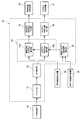
- the steam flow control device 45 is configured to operate from a PV input device 51 that receives PV information from the PV detection device 44, a target steam flow rate (hereinafter referred to as “SV”) and PV, which are set in advance.
- SV target steam flow rate
- MV a supply flow rate calculation unit 53 that calculates the flow rate of the supply gas to the combustion chamber 21 based on the MV, and combustion based on the incinerator temperature and the outlet exhaust gas flow rate
- a reference EGR gas supply flow rate calculation unit 55 that calculates a reference EGR gas supply flow rate to the chamber 21, a combustion air supply flow rate output device 54 that transmits combustion air supply flow rate information to the combustion air supply device 35, and an EGR gas supply device 37
- EGR gas supply flow rate output unit 56 for transmitting the EGR gas supply flow rate information.
- the supply flow rate calculation unit 53 calculates the combustion air supply flow rate to the combustion chamber 21 based on the MV, and supplies the EGR gas to the combustion chamber 21 based on the MV and the reference EGR gas supply flow rate.
- the PV information detected by the PV detection device 44 is transmitted to the PV input device 51 of the steam flow rate control device 45 and used to control the PV from the boiler 41.
- the PV information is transmitted to the MV calculation unit 52 by the PV input device 51, and is used for calculating the MV together with the SV.
- SV is a value preset as a target value or target range of PV from the boiler 41, and is set according to the design specifications of the boiler equipment.
- the MV calculated by the MV calculation unit 52 is transmitted as a signal to the supply flow rate calculation unit 53 and used to calculate at least the combustion air supply flow rate to the combustion chamber 21.
- the combustion air supply flow rate calculation unit 53 a calculates the combustion air supply flow rate to the combustion chamber 21 based on the MV information transmitted from the MV calculation unit 52.
- the combustion air supply flow rate calculated by the combustion air supply flow rate calculation unit 53a is transmitted as a signal to the combustion air supply flow rate output device 54, and is transmitted to the combustion air supply device 35 by the combustion air supply flow rate output device 54.
- the combustion air supply flow rate is calculated based on the theoretical air flow rate calculated from the calorific value setting of SV and general waste, etc. in addition to MV, or the reference air flow rate obtained by multiplying the theoretical air flow rate by the excess air ratio May be.
- the reference EGR gas supply flow rate calculation unit 55 calculates the reference EGR gas to the combustion chamber 21 based on the incinerator temperature detected by the furnace temperature detection device 29 and the outlet exhaust gas flow rate detected by the exhaust gas flow rate detection device 38. Calculate the supply flow rate. Specifically, the reference EGR gas supply flow rate calculation unit 53b increases the reference EGR gas supply flow rate based on the incinerator temperature when the incinerator temperature is higher than a predetermined value. When the outlet exhaust gas flow rate is less than a predetermined value, the reference EGR gas supply flow rate is decreased based on the outlet exhaust gas flow rate so that the exhaust gas recirculation rate does not exceed the set range. The reference EGR gas supply flow rate calculated by the reference EGR gas supply flow rate calculation unit 55 is transmitted as a signal to the EGR gas supply flow rate calculation unit 53b and used to calculate the EGR gas supply flow rate to the combustion chamber 21.
- the EGR gas supply flow rate calculation unit 53b is based on the MV information transmitted from the MV calculation unit 52 and the reference EGR gas supply flow rate information transmitted from the reference EGR gas supply flow rate calculation unit 55. Calculate the supply flow rate.
- the EGR gas supply flow rate calculated by the EGR gas supply flow rate calculation unit 53b is transmitted as a signal to the EGR gas supply flow rate output device 56, and is transmitted to the EGR gas supply device 37 by the EGR gas supply flow rate output device 56.
- the combustion air supply device 35 and the EGR gas supply device 37 each supply combustion air and EGR gas to the combustion chamber 21 according to the received supply flow rate information.
- the supply flow rate calculation unit 53 increases the combustion air supply flow rate when receiving the operating steam flow rate (MV) indicating that the generated steam flow rate (PV) is smaller than the target value steam flow rate (SV), and generates the generated steam flow rate. When the operating steam flow rate (MV) indicating that (PV) is larger than the target steam flow rate (SV) is received, the combustion air supply flow rate is decreased.
- the supply flow rate calculation unit 53 calculates the EGR supply flow rate by increasing / decreasing the calculated value of the combustion air supply flow rate with respect to the operating steam flow rate (MV) in addition to the calculation based on the above-described operating steam flow rate (MV). Increase / decrease the calculated value of.
- FIG. 3 shows a configuration of a first modification of the steam flow control device 45 in the present invention.
- the reference EGR gas supply flow rate information is transmitted from the reference EGR gas supply flow rate calculation unit 55 to the combustion air supply flow rate calculation unit 53a, and is used together with the MV information to calculate the combustion air supply flow rate. .
- the combustion air supply flow rate and the EGR gas supply flow rate are calculated based on the reference EGR gas supply flow rate, so that the balance between the combustion air supply flow rate and the EGR gas supply flow rate is maintained, and general disposal is performed while controlling the PV from the boiler 41. It is possible to effectively suppress the generation of NOx accompanying the incineration of things and the like.
- FIG. 4 shows a configuration of a second modification of the steam flow rate control device 45 in the present invention.
- the EGR gas supply flow rate information is transmitted from the EGR gas supply flow rate calculation unit 53b to the combustion air supply flow rate calculation unit 53a, and is used to calculate the combustion air supply flow rate together with the MV information.
- the combustion air supply flow rate By calculating the combustion air supply flow rate based on the EGR gas supply flow rate, the combustion air supply flow rate, the EGR gas supply flow rate, and the total flow rate thereof are optimized, and more flexible and precise steam flow control becomes possible.
- MV is calculated by PID control.
- PID control By calculating the MV using PID control, an appropriate MV is calculated with a small response delay with respect to a change in PV, and the PV can be brought close to the SV with high accuracy.
Landscapes
- Engineering & Computer Science (AREA)
- Mechanical Engineering (AREA)
- General Engineering & Computer Science (AREA)
- Chemical & Material Sciences (AREA)
- Combustion & Propulsion (AREA)
- Physics & Mathematics (AREA)
- Thermal Sciences (AREA)
- Incineration Of Waste (AREA)
Abstract
焼却炉内の燃焼室への燃焼空気及び排ガス再循環ガスの供給により、焼却炉に設けられたボイラからの発生蒸気流量を制御する、ボイラの蒸気流量制御方法である。この方法は、発生蒸気流量を検出し、発生蒸気流量と目標蒸気流量とから操作蒸気流量を算出し、操作蒸気流量に基づいて燃焼空気供給流量を算出し、燃焼空気を燃焼空気供給流量で燃焼室に供給し、焼却炉内温度と出口排ガス流量に基づいて基準排ガス再循環ガス供給流量を算出し、操作蒸気流量と基準排ガス再循環ガス供給流量に基づいて排ガス再循環ガス供給流量を算出し、排ガス再循環ガスを排ガス再循環ガス供給流量で燃焼室に供給する。
Description
本発明は、一般廃棄物及び産業廃棄物といった廃棄物の焼却炉システムにおける、廃熱回収ボイラからの発生蒸気流量の制御に関し、特に、一般廃棄物等の焼却に伴う窒素酸化物(以下、「NOx」と称する)の排出量を低減することが可能な、ボイラの蒸気流量制御方法及び焼却炉システムに関する。
一般廃棄物等の焼却熱を利用して発生させた蒸気を用いた廃棄物焼却発電が行われている。一般廃棄物等は、通常の火力発電設備において燃料として用いられるガスや重油、石炭などとは異なり、多種多様な物質の混合物であるため、燃焼状態が安定しない。一般廃棄物等の燃焼状態が安定しないことにより、焼却炉の下流側に設けられたボイラへの入熱量が不安定になり、ボイラからの発生蒸気流量が不安定になる。廃棄物焼却発電の発電効率を上げるためには、ボイラからの発生蒸気流量を制御し、発電設備に蒸気を安定供給することが望ましい。
一般廃棄物等の焼却炉システムにおけるボイラからの発生蒸気流量の制御は、通常、焼却内の燃焼室に供給する燃焼空気の流量を変動させることで行われる。例えば、発生蒸気流量が減少した際には、燃焼室への燃焼空気の供給流量を増加させ一般廃棄物等の燃焼を進めることによって発生蒸気流量の回復が図られる。このような蒸気流量制御の問題点として、燃焼空気の供給により燃焼室内の酸素量が全体的又は局所的に過剰になり、酸素と一般廃棄物等や空気に含まれる窒素とが反応することによってNOxの発生量が増加することが知られている。
そこで、燃焼空気の供給により増加したNOxを除去するために、燃焼室の上方にリバーニングゾーンを設け、リバーニングゾーンに天然ガスを供給してNOxを還元する方法(リバーニング法)が提案されている。例えば、蒸気流量計を用いて発生蒸気流量を検出し、検出された発生蒸気流量が所定値よりも低い場合には燃焼室への燃焼空気の供給流量と共にリバーニングゾーンへの天然ガスの供給流量を増加させ、検出された発生蒸気流量が所定値よりも高い場合には燃焼室への燃焼空気の供給流量と共にリバーニングゾーンへの天然ガスの供給流量を減少させるような制御(例えば特許文献1など)が行われている。
しかしながら、特許文献1記載の蒸気流量流制御においては、発生したNOxを除去するための天然ガスが必要であるという課題がある。リバーニング法において必要な天然ガスの量は、一般廃棄物等の熱量に対して約10パーセントにも相当する量である。
本発明は、上述の課題に鑑みてなされたものであり、天然ガス等の追加的な資源を必要とせず、一般廃棄物等の焼却に伴うNOxの発生を抑制することでNOx排出量を低減することが可能な、ボイラの蒸気流量制御方法及び焼却炉システムを提供することを目的とする。
本発明の、焼却炉内の燃焼室への燃焼空気及び排ガス再循環ガスの供給により焼却炉に設けられたボイラからの発生蒸気流量を制御するボイラの蒸気流量制御方法は、
発生蒸気流量を検出し、
発生蒸気流量と予め設定されている目標蒸気流量とから操作蒸気流量を算出し、
操作蒸気流量に基づいて燃焼室への燃焼空気供給流量を算出し、
燃焼空気を前記燃焼空気供給流量で燃焼室に供給し、
焼却炉内温度と出口排ガス流量に基づいて燃焼室への基準排ガス再循環ガス供給流量を算出し、
操作蒸気流量と基準排ガス再循環ガス供給流量に基づいて燃焼室への排ガス再循環ガス供給流量を算出し、
排ガス再循環ガスを排ガス再循環ガス供給流量で燃焼室に供給することを特徴とする。
発生蒸気流量を検出し、
発生蒸気流量と予め設定されている目標蒸気流量とから操作蒸気流量を算出し、
操作蒸気流量に基づいて燃焼室への燃焼空気供給流量を算出し、
燃焼空気を前記燃焼空気供給流量で燃焼室に供給し、
焼却炉内温度と出口排ガス流量に基づいて燃焼室への基準排ガス再循環ガス供給流量を算出し、
操作蒸気流量と基準排ガス再循環ガス供給流量に基づいて燃焼室への排ガス再循環ガス供給流量を算出し、
排ガス再循環ガスを排ガス再循環ガス供給流量で燃焼室に供給することを特徴とする。
本発明に係るボイラの蒸気流量制御方法においては、燃焼空気供給流量を、操作蒸気流量に加えて排ガス再循環ガス供給流量にも基づいて算出することができる。
本発明に係るボイラの蒸気流量制御方法においては、燃焼空気供給流量を、操作蒸気流量に加えて排ガス再循環ガス供給流量にも基づいて算出することができる。
本発明に係るボイラの蒸気流量制御方法においては、操作蒸気流量をPID制御により算出することができる。
本発明の、焼却炉を含み、かつごみ焼却設備及びボイラ設備を備える焼却炉システムでは、前記ごみ焼却設備は、燃焼室と、燃焼空気を燃焼室に供給する燃焼空気供給装置と、排ガス再循環ガスを燃焼室に供給する排ガス再循環ガス供給装置とを備え、前記ボイラ設備は、ボイラと、ボイラからの発生蒸気流量を検出する発生蒸気流量検出装置と、蒸気流量を制御する蒸気流量制御装置とを備え、前記蒸気流量制御装置は、前記発生蒸気流量検出装置から発生蒸気流量情報を受信する発生蒸気流量入力器と、予め設定されている目標蒸気流量と発生蒸気流量とから操作蒸気流量を算出する操作蒸気流量算出部と、操作蒸気流量に基づいて燃焼室への燃焼空気供給流量を算出する燃焼空気供給流量算出部と、前記燃焼空気供給装置に燃焼空気供給流量情報を送信する燃焼空気供給流量出力器と、焼却炉内温度と出口排ガス流量に基づいて燃焼室への基準排ガス再循環ガス供給流量を算出する基準排ガス再循環ガス供給流量算出部と、操作蒸気流量及び基準排ガス再循環ガス供給流量に基づいて燃焼室への排ガス再循環ガス供給流量を算出する排ガス再循環ガス供給流量算出部と、前記排ガス再循環ガス供給装置に排ガス再循環ガス供給流量情報を送信する排ガス再循環ガス供給流量出力器とを有することを特徴とする。
本発明によれば、天然ガス等の追加的な資源を使用することなく、ボイラからの発生蒸気流量を制御しながら、燃焼空気の供給流量と再循環ガスの供給流量とがそれぞれ適正量となるように制御することで、一般廃棄物等の焼却に伴うNOxの発生を抑制することが可能である。
以下、本発明の実施の形態について、図面を参照しながら説明する。
図2において、焼却炉システムの構成の一例としてストーカ炉を含む焼却炉システムの構成を示す。本発明は、ストーカ炉の他、流動床炉等の焼却炉に利用可能であるが、以下では図2に示すようなストーカ炉について述べる。また、図2の説明において、図中上方を上、図中下方を下とし、図中左方を前、図中右方を後とする。
図2は、本発明に係る焼却炉システム1の構成を示す図である。焼却炉システム1は、焼却炉2(ここではストーカ炉)の燃焼制御方法に利用される。焼却炉システム1は、ごみ焼却設備3と、ごみ焼却設備3からの排熱を回収するボイラ設備4とを備える。
焼却炉2はごみ焼却設備3に属し、一般廃棄物等の焼却に供される。ごみ焼却設備3は、焼却炉2内の燃焼室21を少なくとも備え、排ガスの温度を下げるための減温塔31、排ガス中のダストを集塵するためのバグフィルタ32、排ガス中のNOxを無害化させるための触媒塔33、ドラフト効果により排ガスを誘引するための煙突34を必要により備える。バグフィルタ32の後方には、排ガスの流量を検出する排ガス流量検出装置38が設けられており、検出された出口排ガス流量は、信号として蒸気流量制御装置45に送信される。排ガスの一部は、減温塔31、バグフィルタ32及び排ガス流量検出装置38を通ってから回収され、排ガス再循環ガス(以下、「EGRガス」と称する)として燃焼室21に供給される。焼却炉2、減温塔31、バグフィルタ32、排ガス流量検出装置38、触媒塔33、煙突34は、排ガスが流れるダクト(配管)により接続される。
燃焼室21の底部には複数の火格子22が設置されており、一般廃棄物等は燃焼室21において焼却される。焼却される一般廃棄物等は投入ホッパ23に投入され、プッシャ(給じん装置)24によって火格子22上に供給される。各火格子22は、火格子駆動手段25によって前後方向に移動させられ、これによって一般廃棄物等は後方に移動させられる。燃焼室21には、燃焼空気供給装置35から燃焼空気が供給され、EGRガス供給装置37からEGRガスが供給される。燃焼室21内には、焼却炉内温度を検出する炉内温度検出装置29が設けられており、検出された焼却炉内温度は、信号としてボイラ設備4の蒸気流量制御装置45に送信される。
焼却炉2は、煙道中の第1パスに、還元剤(アンモニア水など)を吹き込むことにより、焼却により発生したNOxを還元させても良い。
焼却炉2にはボイラ設備4のボイラ41が付属され、ボイラ41からの発生蒸気は、一般廃棄物等の焼却熱を利用した廃棄物焼却発電に供される。具体的には、焼却炉2には、ごみ焼却設備3からの排熱(すなわち一般廃棄物等の焼却熱)を回収し作動流体(通常は水)を気化するためのボイラ41が設けられている。焼却炉2の煙道の出口には、ボイラ41から発生した蒸気を過熱するための過熱器42が設けられている。
ボイラ設備4は、ボイラ41と、過熱器42と、発電機(タービン)46と、復水器47と、脱気器48と、気化された作動流体にもとづく発生蒸気流量(以下、「PV」と称する)を計測するPV検出装置44と、蒸気流量制御装置45とを備える。ボイラ41、過熱器42、PV検出装置44、発電機46、復水器47及び脱気器48は、作動流体が流れる配管により接続される。
ボイラ41及び過熱器42は、上述のように、ごみ焼却設備3からの排熱を熱源として作動流体を加熱して気化・過熱させる。発電機46では、ボイラ41により気化された作動流体を膨張させて機械的エネルギーを回収して発電が行われる。復水器47は、発電機46にて膨張した作動流体を凝縮して液化させる。作動系には、必要に応じて作動流体(水)が追加供給される。作動流体は、脱気器48にて不純物が取り除かれる。PV検出装置44と発電機46の間には、高圧蒸気溜まり43を設けても良く、高圧蒸気溜まり43の蒸気は焼却炉システム1外に熱供給するための熱源などとして利用される。
PV検出装置44は、気化された作動流体の量であるPVを計測し、PV情報を蒸気流量制御装置45に送信する。蒸気流量制御装置45は、PV検出装置44よりPV情報を受信し、燃焼室21への燃焼空気供給流量及びEGRガス供給流量を算出し、燃焼空気供給流量情報を燃焼空気供給装置35に、EGRガス供給流量情報をEGRガス供給装置37にそれぞれ送信する。燃焼空気供給装置35は、蒸気流量制御装置45から受信した燃焼空気供給流量情報に従い、燃焼空気供給源36からの燃焼空気を火格子22を介して燃焼室21に供給する。EGRガス供給装置37は、蒸気流量制御装置45から受信したEGRガス供給流量情報に従い、EGRガスを第1のEGRガスノズル60から燃焼室21内に前方(乾燥段火格子天井部)及び後方(後燃焼段火格子天井部)または、そのいずれか一方から供給する。
焼却炉2は、燃焼室21のほか、燃焼室21において発生した排ガス中の未燃分を燃焼させるための再燃焼室26を燃焼室21の上方に備えていてもよい。再燃焼室26を設け、空気ノズル27から空気を、第2のEGRガスノズル28からEGRガスを供給することにより未燃分を完全燃焼させることができる。EGRガスは、燃焼室21に供給されることで一般廃棄物等の燃焼を安定化させCOの発生を抑制する効果を発揮するとともに、再燃焼室26に供給されることで再燃焼室26内の空気及び未燃分を攪拌しCOの発生を抑制する効果も発揮する。第2のEGRガスノズル28から供給されるEGRガスは、蒸気流量制御装置45から受信したEGRガス供給流量情報に従い、EGRガスを再燃焼室26内に前方及び後方または、そのいずれか一方から供給することが好ましい。燃焼空気の増減により、一時的に発生するCOを抑制する効果を発揮する。
以下、図1を参照しつつ、本発明に係るボイラの蒸気流量制御方法及び焼却炉システムに用いられる、蒸気流量制御装置45の構成を説明する。蒸気流量制御装置45は、PV検出装置44からPV情報を受信するPV入力器51と、予め設定されている目標蒸気流量(以下、「SV」と称する)とPVとから操作蒸気流量(以下、「MV」と称する)を算出するMV算出部52と、MVに基づいて燃焼室21への供給気体の流量を算出する供給流量算出部53と、焼却炉内温度及び出口排ガス流量に基づいて燃焼室21への基準EGRガス供給流量を算出する基準EGRガス供給流量算出部55と、燃焼空気供給装置35に燃焼空気供給流量情報を送信する燃焼空気供給流量出力器54と、EGRガス供給装置37にEGRガス供給流量情報を送信するEGRガス供給流量出力器56とを有する。供給流量算出部53は、MVに基づいて燃焼室21への燃焼空気供給流量を算出する燃焼空気供給流量算出部53aと、MV及び基準EGRガス供給流量に基づいて燃焼室21へのEGRガス供給流量を算出するEGRガス供給流量算出部53bとを有する。
図1に示すように、PV検出装置44で検出されたPV情報は、蒸気流量制御装置45のPV入力器51に送信され、ボイラ41からのPVを制御するために利用される。PV情報は、PV入力器51によってMV算出部52に送信され、SVとともに、MVを算出するために利用される。SVは、ボイラ41からのPVの目標値又は目標範囲として予め設定される値であり、ボイラ設備の設計仕様により設定される。MV算出部52により算出されたMVは信号として供給流量算出部53に送信され、少なくとも燃焼室21への燃焼空気供給流量を算出するために使用される。
燃焼空気供給流量算出部53aは、MV算出部52から送信されたMV情報に基づき、燃焼室21への燃焼空気供給流量を算出する。燃焼空気供給流量算出部53aによって算出された燃焼空気供給流量は、信号として燃焼空気供給流量出力器54に送信され、燃焼空気供給流量出力器54によって燃焼空気供給装置35に送信される。燃焼空気供給流量は、MVに加えて、SV及び一般廃棄物等の発熱量設定から算出される理論空気流量、又は、理論空気流量に空気過剰率を乗じて得られる基準空気流量に基づいて算出されてもよい。
基準EGRガス供給流量算出部55は、炉内温度検出装置29により検出された焼却炉内温度、及び、排ガス流量検出装置38により検出された出口排ガス流量に基づいて燃焼室21への基準EGRガス供給流量を算出する。具体的には、基準EGRガス供給流量算出部53bは、焼却炉内温度が所定値より高い場合には、焼却炉内温度に基づいて基準EGRガス供給流量を増加させる。また、出口排ガス流量が所定値より少ない場合には、排ガス再循環率が設定範囲を超えないよう、出口排ガス流量に基づいて基準EGRガス供給流量を減少させる。基準EGRガス供給流量算出部55により算出された基準EGRガス供給流量は信号としてEGRガス供給流量算出部53bに送信され、燃焼室21へのEGRガス供給流量を算出するために使用される。
EGRガス供給流量算出部53bは、MV算出部52から送信されたMV情報、及び、基準EGRガス供給流量算出部55から送信された基準EGRガス供給流量情報に基づき、燃焼室21へのEGRガス供給流量を算出する。EGRガス供給流量算出部53bによって算出されたEGRガス供給流量は、信号としてEGRガス供給流量出力器56に送信され、EGRガス供給流量出力器56によってEGRガス供給装置37に送信される。
燃焼空気供給装置35及びEGRガス供給装置37はそれぞれ、受信した供給流量情報に従って燃焼室21に燃焼空気、EGRガスを供給する。
供給流量算出部53は、発生蒸気流量(PV)が目標値蒸気流量(SV)よりも少ないことを示す操作蒸気流量(MV)を受け取った場合には燃焼空気供給流量を増加させ、発生蒸気流量(PV)が目標蒸気流量(SV)よりも多いことを示す操作蒸気流量(MV)を受け取った場合には燃焼空気供給流量を減少させる。供給流量算出部53は、燃焼空気供給流量について、上述した操作蒸気流量(MV)に基づく演算に加え、操作蒸気流量(MV)に対する燃焼空気供給流量の算出値の増加/減少により、EGR供給流量の算出値を増加/減少させる。
このように、燃焼空気供給流量をEGR供給流量と相互補完的に変動させることにより、燃焼空気供給量の増減のみによる蒸気流量制御よりも、燃焼空気供給量の変動幅を低減することが可能である。また、燃焼空気の供給量を低減することにより、燃焼室21内の酸素濃度の変動を抑え、効率的にNOxの発生を抑制することが可能である。
図3に、本発明における、蒸気流量制御装置45の第1の変形例の構成を示す。図3に示すように、好ましくは、基準EGRガス供給流量情報は基準EGRガス供給流量算出部55から燃焼空気供給流量算出部53aに送信され、MV情報とともに燃焼空気供給流量の算出に利用される。
燃焼空気供給流量及びEGRガス供給流量が基準EGRガス供給流量に基づいて算出されることにより、燃焼空気供給流量及びEGRガス供給流量のバランスが保たれ、ボイラ41からのPVを制御しながら一般廃棄物等の焼却に伴うNOxの発生を効果的に抑制することが可能である。
図4に、本発明における、蒸気流量制御装置45の第2の変形例の構成を示す。図4に示すように、好ましくは、EGRガス供給流量情報はEGRガス供給流量算出部53bから燃焼空気供給流量算出部53aに送信され、MV情報とともに燃焼空気供給流量の算出に利用される。
燃焼空気供給流量がEGRガス供給流量に基づいて算出されることにより、燃焼空気供給流量、EGRガス供給流量及びその合計流量が最適になり、より柔軟かつ精密な蒸気流量制御が可能となる。
上においては、SV及びPVからのMVの算出方法を詳述しなかったが、好ましくはMVはPID制御により算出される。PID制御を用いてMVを算出することにより、PVの変化に対し少ない応答遅れで適切なMVが算出され、PVをSVに精度よく近づけることが可能になる。
上述したように、EGRガスを使用する、本発明に係るボイラの蒸気流量制御方法及び焼却炉システムにおいては、天然ガス等の追加的な資源を使用する必要がなく、天然ガス等の購入コストが嵩むおそれがない。
Claims (5)
- 焼却炉内の燃焼室への燃焼空気及び排ガス再循環ガスの供給により焼却炉に設けられたボイラからの発生蒸気流量を制御するボイラの蒸気流量制御方法であって、
発生蒸気流量を検出し、
発生蒸気流量と予め設定されている目標蒸気流量とから操作蒸気流量を算出し、
操作蒸気流量に基づいて燃焼室への燃焼空気供給流量を算出し、
燃焼空気を前記燃焼空気供給流量で燃焼室に供給し、
焼却炉内温度と出口排ガス流量に基づいて燃焼室への基準排ガス再循環ガス供給流量を算出し、
操作蒸気流量と基準排ガス再循環ガス供給流量に基づいて燃焼室への排ガス再循環ガス供給流量を算出し、
排ガス再循環ガスを排ガス再循環ガス供給流量で燃焼室に供給することを特徴とするボイラの蒸気流量制御方法。 - 燃焼空気供給流量を、操作蒸気流量に加えて基準排ガス再循環ガス供給流量にも基づいて算出することを特徴とする請求項1に記載のボイラの蒸気流量制御方法。
- 燃焼空気供給流量を、操作蒸気流量に加えて排ガス再循環ガス供給流量にも基づいて算出することを特徴とする請求項1に記載のボイラの蒸気流量制御方法。
- 操作蒸気流量をPID制御により算出することを特徴とする請求項1乃至3のいずれかに記載のボイラの蒸気流量制御方法。
- 焼却炉を含み、かつごみ焼却設備及びボイラ設備を備える焼却炉システムであって、
前記ごみ焼却設備は、
燃焼室と、
燃焼空気を燃焼室に供給する燃焼空気供給装置と、
排ガス再循環ガスを燃焼室に供給する排ガス再循環ガス供給装置とを備え、
前記ボイラ設備は、
ボイラと、
ボイラからの発生蒸気流量を検出する発生蒸気流量検出装置と、
蒸気流量を制御する蒸気流量制御装置とを備え、
前記蒸気流量制御装置は、
前記発生蒸気流量検出装置から発生蒸気流量情報を受信する発生蒸気流量入力器と、
予め設定されている目標蒸気流量と発生蒸気流量とから操作蒸気流量を算出する操作蒸気流量算出部と、
操作蒸気流量に基づいて燃焼室への燃焼空気供給流量を算出する燃焼空気供給流量算出部と、
前記燃焼空気供給装置に燃焼空気供給流量情報を送信する燃焼空気供給流量出力器と、
焼却炉内温度と出口排ガス流量に基づいて燃焼室への基準排ガス再循環ガス供給流量を算出する基準排ガス再循環ガス供給流量算出部と、
操作蒸気流量及び基準排ガス再循環ガス供給流量に基づいて燃焼室への排ガス再循環ガス供給流量を算出する排ガス再循環ガス供給流量算出部と、
前記排ガス再循環ガス供給装置に排ガス再循環ガス供給流量情報を送信する排ガス再循環ガス供給流量出力器とを有することを特徴とする焼却炉システム。
Priority Applications (1)
| Application Number | Priority Date | Filing Date | Title |
|---|---|---|---|
| PCT/JP2015/083923 WO2017094150A1 (ja) | 2015-12-02 | 2015-12-02 | ボイラの蒸気流量制御方法及び焼却炉システム |
Applications Claiming Priority (1)
| Application Number | Priority Date | Filing Date | Title |
|---|---|---|---|
| PCT/JP2015/083923 WO2017094150A1 (ja) | 2015-12-02 | 2015-12-02 | ボイラの蒸気流量制御方法及び焼却炉システム |
Publications (1)
| Publication Number | Publication Date |
|---|---|
| WO2017094150A1 true WO2017094150A1 (ja) | 2017-06-08 |
Family
ID=58796608
Family Applications (1)
| Application Number | Title | Priority Date | Filing Date |
|---|---|---|---|
| PCT/JP2015/083923 Ceased WO2017094150A1 (ja) | 2015-12-02 | 2015-12-02 | ボイラの蒸気流量制御方法及び焼却炉システム |
Country Status (1)
| Country | Link |
|---|---|
| WO (1) | WO2017094150A1 (ja) |
Citations (7)
| Publication number | Priority date | Publication date | Assignee | Title |
|---|---|---|---|---|
| JPS60251315A (ja) * | 1984-05-25 | 1985-12-12 | Babcock Hitachi Kk | 触媒燃焼加熱炉の制御方法 |
| JPS61235601A (ja) * | 1985-04-11 | 1986-10-20 | 横河電機株式会社 | ガス再循環ボイラ制御装置 |
| JPS6446506A (en) * | 1987-08-12 | 1989-02-21 | Babcock Hitachi Kk | Boiler furnace |
| JPH03199806A (ja) * | 1989-12-28 | 1991-08-30 | Babcock Hitachi Kk | 流動層燃焼装置 |
| JPH04254101A (ja) * | 1991-06-21 | 1992-09-09 | Nkk Corp | ごみ焼却炉の燃焼制御方法 |
| JPH11294740A (ja) * | 1998-04-07 | 1999-10-29 | Takuma Co Ltd | 排ガス完全燃焼制御方法および排ガス完全燃焼制御装置 |
| JP2001041403A (ja) * | 1999-07-30 | 2001-02-13 | Babcock Hitachi Kk | ボイラ制御装置 |
-
2015
- 2015-12-02 WO PCT/JP2015/083923 patent/WO2017094150A1/ja not_active Ceased
Patent Citations (7)
| Publication number | Priority date | Publication date | Assignee | Title |
|---|---|---|---|---|
| JPS60251315A (ja) * | 1984-05-25 | 1985-12-12 | Babcock Hitachi Kk | 触媒燃焼加熱炉の制御方法 |
| JPS61235601A (ja) * | 1985-04-11 | 1986-10-20 | 横河電機株式会社 | ガス再循環ボイラ制御装置 |
| JPS6446506A (en) * | 1987-08-12 | 1989-02-21 | Babcock Hitachi Kk | Boiler furnace |
| JPH03199806A (ja) * | 1989-12-28 | 1991-08-30 | Babcock Hitachi Kk | 流動層燃焼装置 |
| JPH04254101A (ja) * | 1991-06-21 | 1992-09-09 | Nkk Corp | ごみ焼却炉の燃焼制御方法 |
| JPH11294740A (ja) * | 1998-04-07 | 1999-10-29 | Takuma Co Ltd | 排ガス完全燃焼制御方法および排ガス完全燃焼制御装置 |
| JP2001041403A (ja) * | 1999-07-30 | 2001-02-13 | Babcock Hitachi Kk | ボイラ制御装置 |
Similar Documents
| Publication | Publication Date | Title |
|---|---|---|
| JP5436456B2 (ja) | 反応器サブシステムを用いた空気燃焼co2捕捉対応の循環流動層熱発生 | |
| JP2016053953A (ja) | プラントの少なくとも1つの動作パラメータを制御するための装置及び方法 | |
| JP4542417B2 (ja) | 廃棄物溶融炉の可燃性ガスの処理方法 | |
| JP2013117336A (ja) | ストーカ式焼却炉の燃焼方法及び燃焼装置 | |
| JP2006015179A (ja) | 排ガス処理装置、廃棄物処理装置、及び排ガス処理方法 | |
| CN101354129A (zh) | 生物质、燃煤复合燃料锅炉 | |
| JP7126215B2 (ja) | システム制御装置及び制御方法 | |
| JP2005291524A (ja) | バイオマス燃料の燃焼装置及び方法 | |
| CN113623664A (zh) | 一种煤粉锅炉和炉排炉联用的垃圾焚烧发电系统及方法 | |
| WO2017094150A1 (ja) | ボイラの蒸気流量制御方法及び焼却炉システム | |
| CN215637210U (zh) | 一种煤粉锅炉和炉排炉联用的垃圾焚烧发电系统 | |
| JP6797083B2 (ja) | 一次燃焼用気体の供給制御方法、蒸発量安定化方法、発電量安定化方法、及び火格子式廃棄物焼却炉 | |
| TW202346756A (zh) | 廢棄物焚化設備 | |
| JP2020020503A (ja) | 廃棄物焼却設備の脱硝及び腐食低減方法 | |
| JPS6238601B2 (ja) | ||
| JP2013096685A (ja) | 廃棄物焼却炉の燃焼方法 | |
| Ruth | Advanced coal-fired power plants | |
| JP3288751B2 (ja) | 熱回収焼却炉 | |
| JP2021071238A (ja) | 焼却プラント及びその燃焼制御方法 | |
| JP2004060992A (ja) | 焼却炉用廃熱回収ボイラ | |
| JP6797082B2 (ja) | 一次燃焼用気体の供給制御方法、蒸発量安定化方法、発電量安定化方法、及び火格子式廃棄物焼却炉 | |
| JP4082416B2 (ja) | 廃棄物処理プラント | |
| JP6916854B2 (ja) | 廃棄物焼却設備の脱硝及び腐食低減方法 | |
| JP6125543B2 (ja) | 流動床燃焼炉及び流動床燃焼炉の運転方法 | |
| JP2004316960A (ja) | ごみ焼却プラントの自動燃焼制御方法及び装置 |
Legal Events
| Date | Code | Title | Description |
|---|---|---|---|
| 121 | Ep: the epo has been informed by wipo that ep was designated in this application |
Ref document number: 15909780 Country of ref document: EP Kind code of ref document: A1 |
|
| NENP | Non-entry into the national phase |
Ref country code: DE |
|
| 122 | Ep: pct application non-entry in european phase |
Ref document number: 15909780 Country of ref document: EP Kind code of ref document: A1 |
|
| NENP | Non-entry into the national phase |
Ref country code: JP |