WO2017090718A1 - 不活性ガスの置換方法、及び不活性ガスの置換方法を用いたセラミック構造体の製造方法 - Google Patents
不活性ガスの置換方法、及び不活性ガスの置換方法を用いたセラミック構造体の製造方法 Download PDFInfo
- Publication number
- WO2017090718A1 WO2017090718A1 PCT/JP2016/084943 JP2016084943W WO2017090718A1 WO 2017090718 A1 WO2017090718 A1 WO 2017090718A1 JP 2016084943 W JP2016084943 W JP 2016084943W WO 2017090718 A1 WO2017090718 A1 WO 2017090718A1
- Authority
- WO
- WIPO (PCT)
- Prior art keywords
- pressure
- inert gas
- vacuum pressure
- furnace
- closed space
- Prior art date
- Legal status (The legal status is an assumption and is not a legal conclusion. Google has not performed a legal analysis and makes no representation as to the accuracy of the status listed.)
- Ceased
Links
Images




Classifications
-
- C—CHEMISTRY; METALLURGY
- C04—CEMENTS; CONCRETE; ARTIFICIAL STONE; CERAMICS; REFRACTORIES
- C04B—LIME, MAGNESIA; SLAG; CEMENTS; COMPOSITIONS THEREOF, e.g. MORTARS, CONCRETE OR LIKE BUILDING MATERIALS; ARTIFICIAL STONE; CERAMICS; REFRACTORIES; TREATMENT OF NATURAL STONE
- C04B38/00—Porous mortars, concrete, artificial stone or ceramic ware; Preparation thereof
- C04B38/0006—Honeycomb structures
-
- C—CHEMISTRY; METALLURGY
- C04—CEMENTS; CONCRETE; ARTIFICIAL STONE; CERAMICS; REFRACTORIES
- C04B—LIME, MAGNESIA; SLAG; CEMENTS; COMPOSITIONS THEREOF, e.g. MORTARS, CONCRETE OR LIKE BUILDING MATERIALS; ARTIFICIAL STONE; CERAMICS; REFRACTORIES; TREATMENT OF NATURAL STONE
- C04B35/00—Shaped ceramic products characterised by their composition; Ceramics compositions; Processing powders of inorganic compounds preparatory to the manufacturing of ceramic products
- C04B35/515—Shaped ceramic products characterised by their composition; Ceramics compositions; Processing powders of inorganic compounds preparatory to the manufacturing of ceramic products based on non-oxide ceramics
- C04B35/56—Shaped ceramic products characterised by their composition; Ceramics compositions; Processing powders of inorganic compounds preparatory to the manufacturing of ceramic products based on non-oxide ceramics based on carbides or oxycarbides
- C04B35/565—Shaped ceramic products characterised by their composition; Ceramics compositions; Processing powders of inorganic compounds preparatory to the manufacturing of ceramic products based on non-oxide ceramics based on carbides or oxycarbides based on silicon carbide
-
- C—CHEMISTRY; METALLURGY
- C04—CEMENTS; CONCRETE; ARTIFICIAL STONE; CERAMICS; REFRACTORIES
- C04B—LIME, MAGNESIA; SLAG; CEMENTS; COMPOSITIONS THEREOF, e.g. MORTARS, CONCRETE OR LIKE BUILDING MATERIALS; ARTIFICIAL STONE; CERAMICS; REFRACTORIES; TREATMENT OF NATURAL STONE
- C04B35/00—Shaped ceramic products characterised by their composition; Ceramics compositions; Processing powders of inorganic compounds preparatory to the manufacturing of ceramic products
- C04B35/622—Forming processes; Processing powders of inorganic compounds preparatory to the manufacturing of ceramic products
- C04B35/64—Burning or sintering processes
-
- F—MECHANICAL ENGINEERING; LIGHTING; HEATING; WEAPONS; BLASTING
- F27—FURNACES; KILNS; OVENS; RETORTS
- F27B—FURNACES, KILNS, OVENS OR RETORTS IN GENERAL; OPEN SINTERING OR LIKE APPARATUS
- F27B9/00—Furnaces through which the charge is moved mechanically, e.g. of tunnel type; Similar furnaces in which the charge moves by gravity
- F27B9/04—Furnaces through which the charge is moved mechanically, e.g. of tunnel type; Similar furnaces in which the charge moves by gravity adapted for treating the charge in vacuum or special atmosphere
-
- F—MECHANICAL ENGINEERING; LIGHTING; HEATING; WEAPONS; BLASTING
- F27—FURNACES; KILNS; OVENS; RETORTS
- F27D—DETAILS OR ACCESSORIES OF FURNACES, KILNS, OVENS OR RETORTS, IN SO FAR AS THEY ARE OF KINDS OCCURRING IN MORE THAN ONE KIND OF FURNACE
- F27D7/00—Forming, maintaining or circulating atmospheres in heating chambers
- F27D7/06—Forming or maintaining special atmospheres or vacuum within heating chambers
-
- C—CHEMISTRY; METALLURGY
- C04—CEMENTS; CONCRETE; ARTIFICIAL STONE; CERAMICS; REFRACTORIES
- C04B—LIME, MAGNESIA; SLAG; CEMENTS; COMPOSITIONS THEREOF, e.g. MORTARS, CONCRETE OR LIKE BUILDING MATERIALS; ARTIFICIAL STONE; CERAMICS; REFRACTORIES; TREATMENT OF NATURAL STONE
- C04B2111/00—Mortars, concrete or artificial stone or mixtures to prepare them, characterised by specific function, property or use
- C04B2111/00474—Uses not provided for elsewhere in C04B2111/00
- C04B2111/00793—Uses not provided for elsewhere in C04B2111/00 as filters or diaphragms
-
- C—CHEMISTRY; METALLURGY
- C04—CEMENTS; CONCRETE; ARTIFICIAL STONE; CERAMICS; REFRACTORIES
- C04B—LIME, MAGNESIA; SLAG; CEMENTS; COMPOSITIONS THEREOF, e.g. MORTARS, CONCRETE OR LIKE BUILDING MATERIALS; ARTIFICIAL STONE; CERAMICS; REFRACTORIES; TREATMENT OF NATURAL STONE
- C04B2235/00—Aspects relating to ceramic starting mixtures or sintered ceramic products
- C04B2235/65—Aspects relating to heat treatments of ceramic bodies such as green ceramics or pre-sintered ceramics, e.g. burning, sintering or melting processes
- C04B2235/658—Atmosphere during thermal treatment
- C04B2235/6581—Total pressure below 1 atmosphere, e.g. vacuum
-
- C—CHEMISTRY; METALLURGY
- C04—CEMENTS; CONCRETE; ARTIFICIAL STONE; CERAMICS; REFRACTORIES
- C04B—LIME, MAGNESIA; SLAG; CEMENTS; COMPOSITIONS THEREOF, e.g. MORTARS, CONCRETE OR LIKE BUILDING MATERIALS; ARTIFICIAL STONE; CERAMICS; REFRACTORIES; TREATMENT OF NATURAL STONE
- C04B2235/00—Aspects relating to ceramic starting mixtures or sintered ceramic products
- C04B2235/65—Aspects relating to heat treatments of ceramic bodies such as green ceramics or pre-sintered ceramics, e.g. burning, sintering or melting processes
- C04B2235/658—Atmosphere during thermal treatment
- C04B2235/6583—Oxygen containing atmosphere, e.g. with changing oxygen pressures
- C04B2235/6584—Oxygen containing atmosphere, e.g. with changing oxygen pressures at an oxygen percentage below that of air
Definitions
- the present invention relates to an inert gas replacement method and a method for manufacturing a ceramic structure using the inert gas replacement method. More specifically, an inert gas for replacing a closed space isolated from the outside with an inert gas such as argon gas or nitrogen gas is performed in a firing process for manufacturing a ceramic structure such as a honeycomb structure.
- the present invention relates to a replacement method and a method for manufacturing a ceramic structure using the inert gas replacement method (hereinafter simply referred to as “a method for manufacturing a ceramic structure”).
- ceramic honeycomb structures which are a type of ceramic structure, have been used in a wide range of applications such as automobile exhaust gas purification catalyst carriers, diesel particulate removal filters, or combustion device heat storage bodies.
- a ceramic honeycomb structure (hereinafter simply referred to as “honeycomb structure”) is prepared by preparing a forming raw material (kneaded material) and extruding it into a desired honeycomb shape using an extrusion molding machine.
- the honeycomb formed body that has been finish-cut is manufactured through a firing step of firing at a high temperature.
- the firing process of the honeycomb formed body can be roughly divided into two steps. For example, organic substances and carbides contained in the honeycomb formed body are heated and removed in an air atmosphere. And a main firing step in which the honeycomb formed body after the binder removal step is heated and sintered at a high temperature.
- honeycomb structures there are two types of honeycomb structures: those using oxide ceramics as raw materials and those using non-oxide ceramics.
- oxide ceramics can be fired in an air atmosphere
- non-oxide ceramics need to be fired in an inert gas such as argon gas that is a non-oxidizing atmosphere.
- the present invention particularly relates to firing of a honeycomb structure made of non-oxide ceramics.
- the main firing step may be performed using a continuous firing furnace or a single firing furnace, and the continuous firing furnace is particularly suitable for mass production of honeycomb structures.
- the continuous firing furnace in order to perform the firing process under an inert gas, airtightness is maintained between the firing furnace and the outside on the upstream side and the downstream side of the firing furnace, respectively.
- a gas replacement chamber having a pair of airtight shutters that can be shut off is provided. Thereby, before introducing the honeycomb formed body into the main firing furnace and before removing the fired honeycomb fired body from the main firing furnace, the interior space (closed space) of the gas replacement chamber is replaced with the inert gas. It is possible to prevent the atmosphere from entering the furnace space of the main firing furnace.
- the space in the furnace of the single firing furnace is a closed space, and the inert gas is replaced with the furnace space before and after the main firing by high-temperature heating. Done.
- FIG. 7 shows the gas replacement chamber 101 connected to the main firing furnace.
- the furnace-side airtight shutter 102a provided between the gas replacement chamber 101 and the furnace interior space of the main firing furnace is closed in advance, and the interior space 103 of the furnace and the gas replacement chamber 101 (corresponding to a closed space).
- the airtightness between is maintained.
- the honeycomb formed body is conveyed to the indoor space 103 from the introduction port where one (external side) hermetic shutter 102b is opened.
- illustration of the conveyed honeycomb formed body is omitted.
- the external airtight shutter 102b is closed, and the indoor space 103 of the gas replacement chamber 101 is closed by the pair of airtight shutters 102a and 102b (closing step S101).
- the indoor space 103 is filled with the atmosphere A, and the atmosphere A does not leak into the furnace space of the main firing furnace or outside.
- the interior space 103 is decompressed to a preset vacuum pressure using decompression means (not shown) such as a vacuum pump, and the vacuum state is maintained (decompression step S102).
- the set vacuum pressure is, for example, about 5% of the atmospheric pressure.
- most of the indoor space 103 becomes the vacuum region V, and the atmosphere A remains slightly.
- the vacuum region V and the atmosphere A are separated and exist in the indoor space 103, but this is for simplifying the illustration.
- the atmosphere A is mixed and present (the same applies hereinafter).
- the operation of the decompression means is stopped, and the inert gas 104 (argon gas or the like) is introduced into the indoor space 103 (return pressure step S103).
- the introduction of the inert gas 104 is restored until the indoor space 103 reaches the same pressure as the atmospheric pressure, that is, until the pressure reaches 100% with respect to the atmospheric pressure.
- the pressure reduction of the indoor space 103 pressure reduction step S102
- the return pressure to the atmospheric pressure return pressure step S103
- the furnace-side airtight shutter 102a is opened, and the interior of the main firing furnace is opened.
- the space and the indoor space 103 are communicated with each other, and the honeycomb formed body is transferred to the furnace space (transfer step S104).
- the honeycomb formed body can be transported while avoiding intrusion of oxygen, nitrogen, or the like in the atmosphere into the furnace space of the firing furnace set in advance under an inert gas.
- the gas replacement chamber installed on the downstream side of the main firing furnace, there is an inert gas replacement method similar to the above so that oxygen or the like does not enter the furnace space when the fired honeycomb fired body is taken out.
- opening and closing between the furnace space (closed space) and the outside are performed by an airtight shutter provided at the furnace opening of the single firing furnace.
- the furnace space can be replaced with an inert gas or the like. Firing is performed in an inert gas, and after cooling in the furnace, the space in the furnace is replaced with air.
- the conventional inert gas replacement method may be problematic in the following points. That is, as the inert gas that replaces the atmosphere in the indoor space (closed space) of the gas replacement chamber, an inert gas such as argon gas, nitrogen gas, or other rare gas is generally used.
- argon gas is present at 0.93% in the atmosphere, and it is liquefied by cooling the atmosphere at a very low temperature and fractionated with oxygen, nitrogen, and other gas components, thereby increasing the amount of argon gas. Produced by separation and purification to purity.
- the present invention reduces the amount of inert gas used in the replacement of the inert gas performed in the firing step (main firing step), and the manufacturing cost of a ceramic structure such as a honeycomb structure. It is an object of the present invention to provide an inert gas replacement method capable of realizing the above effects using existing equipment, and a ceramic structure manufacturing method using the inert gas replacement method. is there.
- the closed space is an indoor space of a gas replacement chamber connected to at least one of the upstream and downstream furnace openings of the firing furnace for firing the ceramic body, and the gas replacement chamber and
- an airtight shutter capable of closing the closed space and the in-furnace space of the firing furnace while maintaining airtightness is installed between the furnace openings of the firing furnace.
- the closed space is an in-furnace space of a firing furnace for firing the ceramic body, and an airtight shutter is installed at a furnace opening of the firing furnace, according to [1] or [2] Inert gas replacement method.
- the second vacuum pressure is adjusted so that the vacuum pressure becomes constant in each of the pressure-increasing steps repeated at least twice, or the vacuum pressure increases each time the pressure-increasing step is performed.
- the inert gas replacement method according to any one of [1] to [4], which is adjusted to be
- the first vacuum pressure is adjusted to a range of 0.1 to 5 kPa, and the second vacuum pressure is adjusted to a range of 12 to 50 kPa.
- Inert gas replacement method is used.
- An inert gas is introduced into the pressure increasing step of increasing the closed space to a second vacuum pressure higher than the first vacuum pressure and lower than the atmospheric pressure, and the increased closed space is increased to the first vacuum pressure.
- the method for replacing the inert gas in the firing step is a method for manufacturing a ceramic structure using the inert gas replacement method according to [11], wherein the pressure increasing step and the re-depressurizing step are repeated four times. Method.
- the second vacuum pressure is adjusted so that the vacuum pressure becomes constant in each of the pressure increasing steps repeated at least twice, or the pressure increase is performed.
- the amount of inert gas used can be reduced using existing equipment, and the manufacturing cost of a ceramic structure such as a honeycomb structure can be reduced. Furthermore, according to the method for manufacturing a ceramic structure of the present invention, the ceramic structure can be manufactured at a low manufacturing cost by using the above-described inert gas replacement method in the firing step.
- inert gas replacement method and the ceramic structure manufacturing method of the present invention are not particularly limited to the following embodiments, and various design changes can be made without departing from the gist of the present invention. Modifications, improvements, etc. can be added.
- the inert gas replacement method 1 (hereinafter simply referred to as “replacement method 1” according to one embodiment of the present invention, refer to FIGS. 2 and 3) has a ceramic structure. It is carried out in a firing step of firing a honeycomb formed body (corresponding to a ceramic body in the present invention) for manufacturing a honeycomb structure as a body.
- the honeycomb formed body has a grid-shaped partition wall and an outer peripheral wall that form a plurality of cells extending from one end surface to the other end surface, which are formed by a molding process of extruding a previously prepared molding material. Is.
- the replacement method 1 of the present embodiment is performed in a firing step, which is a step of firing a honeycomb formed body, in the method for manufacturing a ceramic structure of the present invention, and a ceramic structure (honeycomb structure). Is a part of the manufacturing method.
- the firing process is mainly divided into a binder removal process and a main firing process as shown in FIG. 1, and the replacement method 1 of the present embodiment is a main firing furnace 2 in which the main firing process is performed. What is implemented in a pair of gas replacement chambers 3a and 3b provided on the upstream side and the downstream side of FIG.
- the main firing furnace 2 does not remove the honeycomb molded body 5 (corresponding to a ceramic body) from which the fats and oils, organic substances, and the like have been removed, sent from the debinder furnace 4 where the binder removal process, which is a pre-process of the main firing process, is performed. It is for firing at a high temperature under an active gas atmosphere, exhibits a longitudinal shape, and moves the honeycomb formed body 5 introduced into the furnace space 2a from one furnace opening 6a at a constant speed along the horizontal direction, The main firing can be performed until the other furnace opening 6b is reached.
- Gas replacement chambers 3a and 3b are provided so as to be connected to the pair of furnace openings 6a and 6b of the main firing furnace 2, respectively.
- the gas replacement chambers 3a and 3b are closed in a state in which the space between the furnace space 2a of the main firing furnace 2 and the indoor spaces 7a and 7b (closed spaces) of the gas replacement chambers 3a and 3b are kept open and airtight.
- the gas replacement chambers 3a and 3b include a decompression unit 9 such as a vacuum pump for decompressing the indoor spaces 7a and 7b until reaching a preset vacuum pressure, and an argon gas 10 in the decompressed indoor spaces 7a and 7b. And a gas introduction part 11 for introducing the gas.
- the argon gas 10 corresponds to the inert gas of the present invention.
- the decompression section 9 and the gas introduction section 11 can use the equipment used in the existing inert gas replacement method as they are, and detailed description thereof is omitted here. Further, a control unit (not shown) equipped with a control program for controlling the timing and time of decompression by the decompression unit 9 and the introduction amount and introduction timing of the argon gas 10 by the gas introduction unit 11 is provided by the decompression unit 9 and the gas. Each is electrically connected to the introduction part 11.
- the honeycomb formed body 5 introduced into the gas replacement chamber 3a includes a lattice-shaped partition wall that partitions and forms a plurality of cells extending from one end face to the other end face.
- the thing made from the non-oxide ceramics which has an outer peripheral wall and has silicon carbide which has a substantially columnar shape as a main component is used.
- the honeycomb formed bodies 5 loaded on the firing setter (not shown) are respectively introduced into the gas replacement chamber 3a.
- the honeycomb structure 12 loaded on the firing setter fired by the main firing furnace 2 is taken out from the main firing furnace 2 through the gas replacement chamber 3b.
- FIGS. 3 An example of the replacement process of the argon gas 10 by the replacement method 1 of the present embodiment using the main firing furnace 2 and the gas replacement chambers 3a and 3b is shown in FIGS.
- the flow of the replacement process in the stage before the honeycomb formed body 5 is introduced into the main firing furnace 2, that is, the gas replacement chamber 3a provided on the upstream side of the main firing furnace 2.
- the furnace-side airtight shutter 8a As an initial state, the furnace-side airtight shutter 8a provided between the furnace opening 6a on the upstream side of the main firing furnace 2 and the gas replacement chamber 3a is closed in advance.
- the pair of honeycomb molded bodies 5 after the completion of the binder removal process are transferred to the indoor space 7a of the gas replacement chamber 3a through the gas replacement chamber opening 14 of the gas replacement chamber 3a in which the outer airtight shutter 8b is opened.
- the conveyed honeycomb formed body 5 is not shown in order to clarify the state of the argon gas 10 and the like in the indoor space 7a.
- the external airtight shutter 8b that shuts off the flow between the indoor space 7a of the gas replacement chamber 3a and the outside is closed (closing step S1).
- the honeycomb molded body 5 is accommodated in the indoor space 7a of the gas replacement chamber 3a, and the airtightness between the interior space 2a of the main firing furnace 2 and the outside is maintained by the pair of airtight shutters 8a and 8b.
- the indoor space 7a is closed in a leaned state.
- the indoor space 7a of the closed gas replacement chamber 3a is filled with the atmosphere A containing oxygen, nitrogen and the like, and has the same pressure as the atmospheric pressure (1 atm).
- the atmosphere A existing in the indoor space 7a does not leak into the in-furnace space 2a of the main firing furnace 2 filled with the argon gas 10 in advance.
- the external atmosphere A does not leak into the indoor space 7a of the gas replacement chamber 3a.
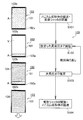
- the decompression unit 9 is controlled to decompress the indoor space 7a of the gas replacement chamber 3a to a first vacuum pressure set in advance (decompression step S2).
- decompression step S2 a first vacuum pressure set in advance
- the atmosphere A in the indoor space 7a still remaining after the decompression step S2 is shown in the lower part of the indoor space 7a, and the decompressed vacuum region V is shown in the upper part.
- the atmosphere A and the vacuum region V are diffused and present throughout the indoor space 7a.
- the first vacuum pressure is adjusted in the range of 0.1 to 5 kPa, preferably in the range of 2.0 to 4.3 kPa. Reducing the value of the first vacuum pressure to less than 0.1 kPa requires an excessive load and reaches the first vacuum pressure to be achieved by the decompression unit 9 configured using an existing vacuum pump or the like. The decompression time may be long. On the other hand, when the value of the first vacuum pressure is higher than 5 kPa, the atmosphere A (oxygen) remaining at the time of depressurization increases, and sufficient replacement of the argon gas 10 cannot be performed. Therefore, the first vacuum pressure is limited to the above numerical range.
- the gas introduction unit 11 is controlled to introduce the argon gas 10 into the decompressed indoor space 7a (intensification step S3).
- the pressure in the indoor space 7a into which the argon gas 10 is introduced by the gas introduction unit 11 is higher than the first vacuum pressure reduced in the pressure reduction step S2, and the vacuum pressure is higher than the atmospheric pressure before the pressure reduction.
- the pressure increase is kept up to a low second vacuum pressure.
- the indoor space 7a is not subjected to 100% return pressure completely filled with the argon gas 10, but shows a pressure lower than the atmospheric pressure, and the first gas is introduced by the argon gas 10 introduced into the indoor space 7a.
- the second vacuum pressure which is higher than the vacuum pressure, is maintained. Therefore, as shown in FIG. 2 (see the second figure from the lower left), the indoor space 7a after the pressure increasing step S3 is filled with the three components of the vacuum region V, the argon gas 10, and the atmosphere A. It will be.
- the second vacuum pressure is adjusted in the range of 12 to 50 kPa, preferably in the range of 14 to 30 kPa.
- the value of the second vacuum pressure is lower than 12 kPa, it becomes difficult to achieve the effect of substitution with the argon gas 10.
- the value of the second vacuum pressure is higher than 50 kPa, the usage amount of the argon gas 10 used for increasing the pressure increases, and it becomes difficult to reduce the total usage amount of the argon gas 10. Therefore, the second vacuum pressure is limited to the above numerical range.
- the indoor space 7a is again decompressed to the first vacuum pressure (redepressurizing step S4). Thereby, the ratio of the atmosphere A such as oxygen remaining in the indoor space 7a is further reduced.
- the pressure increasing step S3 and the re-depressurizing step S4 are repeated at least twice, more preferably four times or more (see FIG. 3). By repeating the pressure increasing step S3 and the re-depressurizing step S4 a plurality of times, the oxygen concentration of oxygen remaining in the indoor space 7a is lowered. Thereby, the possibility that the atmosphere A remains in the indoor space 7a is close to 0%.
- the argon gas 10 is introduced into the indoor space 7a that has been decompressed to the first vacuum pressure, and the indoor space 7a is decompressed to atmospheric pressure.
- the indoor space 7a is in a state where the pressure is 100% refilled with the inert argon gas 10 (return pressure step S5).
- the furnace-side airtight shutter 8a is opened, and the main firing furnace 2 and the gas replacement chamber 3a are communicated.
- the honeycomb formed body 5 accommodated in the gas replacement chamber 3a is transported to the furnace space 2a of the main firing furnace 2 (transport step S6).
- the airtight shutter 8a is opened in a state where the indoor space 7a of the gas replacement chamber 3a is placed in the same atmosphere of the argon gas 10 as the furnace space 2a of the main firing furnace 2 filled with the argon gas 10, and the communication is performed.
- the honeycomb formed body 5 can be transported from the gas replacement chamber 3a to the main firing furnace 2.
- oxygen, nitrogen, etc. present in the atmosphere A do not enter the furnace space 2a, and the presence of oxygen does not particularly affect the quality of the main firing of the honeycomb formed body 5. Therefore, the honeycomb formed body 5 can be fired under stable firing conditions to obtain the honeycomb structure 12.
- the value of the pressure (second vacuum pressure) in the indoor space 7a of the pressure increasing step S3 that is performed a plurality of times is adjusted so as to be always a constant vacuum pressure, or pressure increase
- the adjustment may be performed so that the vacuum pressure gradually increases (the pressure value decreases) each time.
- the argon gas 10 is introduced into the indoor space 7a by the decompression step S5, and the oxygen concentration in the indoor space 7a before opening the airtight shutter 8a can be reduced to 500 ppm or less.
- the oxygen concentration in the indoor space 7a is 500 ppm or less, even when the main firing step is performed using the main firing furnace 2, the firing of the honeycomb formed body 5 is not greatly affected.
- the pressure increase due to gas leakage between the indoor space 7a (closed space) of the gas replacement chamber 3a and the furnace space 2a or the outside is 1.0 Pa or less per second.
- the vacuum pressure in the decompression step S2 and the re-decompression step S4 in the above-described range of 0.1 to 5 kPa, the vacuum pressure can be sufficiently reached even by using an existing vacuum pump. . Therefore, new equipment such as a higher performance vacuum pump is not required, and the equipment cost can be suppressed.
- the pressure is not restored to atmospheric pressure, but the introduction of argon gas is suppressed to a second vacuum pressure that is higher than the first vacuum pressure during pressure reduction and lower than atmospheric pressure. Is done. Thereby, the usage-amount of argon gas can be suppressed.
- Example 2 The value of the oxygen concentration with respect to the number of substitutions of argon gas, and the amount of argon gas used Example 1 was obtained by repeating the decompression and pressure increasing processes four times, and Example 2 was performed five times. It is repeated. At this time, the vacuum pressure at the time of depressurization (first vacuum pressure) is set to 4300 Pa in all cases, and the vacuum pressure at the time of pressure increase (second vacuum pressure) is set to 14000 Pa in all cases.
- Comparative Example 1 was obtained by repeating 100% decompression up to reduced pressure and atmospheric pressure twice according to the conventional inert gas replacement method, and Comparative Example 2 was using a vacuum pump capable of reaching high vacuum. The pressure was reduced to 100 Pa at a time, and then 100% return pressure was performed to atmospheric pressure.
- Comparative Example 3 shows a case where the process of reducing the pressure to 4300 Pa and increasing the pressure to 14000 Pa was repeated three times as in Example 1 and Example 2.
- the ratio of the usage-amount of argon gas has shown the ratio for the usage-amount of the comparative example 1 as 100%.
- Example 1 and Example 2 without increasing the pressure to 100% from the reduced pressure state to the atmospheric pressure, the pressure increase was stopped by the second vacuum pressure (14000 Pa), By repeating the process, the amount of argon gas used can be significantly reduced compared to the conventional method. Further, if the number of substitutions is four or five, the oxygen concentration can be suppressed to 500 ppm or less which is defined in advance, and the firing furnace does not hinder the firing of the honeycomb formed body.
- Comparative Example 1 the amount of argon gas used is significantly increased as in the prior art, and an increase in manufacturing cost becomes a problem.
- Comparative Example 2 has the advantages of reducing the amount of argon gas used and lowering the oxygen concentration.
- it is necessary to prepare a vacuum pump that can reach a high vacuum, which requires new equipment investment and a filter member for collecting fine dust in the indoor space. The cost of the filter member and the burden required for replacement and inspection may increase.
- Comparative Example 3 when the number of substitutions is three, it is possible to suppress the amount of argon gas used, but since the oxygen concentration exceeds the specified value, there is a problem in firing the honeycomb formed body. Can have occurred.
- FIG. 6 shows the results of an experiment conducted assuming that the amount of argon gas used is reduced by 30% compared to the conventional method.
- Comparative example 1 and comparative example 2 are the same as those shown in FIG.
- pressure reduction and pressure increase treatments were performed three times, four times, and five times, respectively.
- the second vacuum pressure at the time of increasing pressure in Example 3 is 24000 Pa
- the second vacuum pressure at the time of increasing pressure in Example 4 is 17500 Pa
- the second vacuum pressure at the time of increasing pressure in Example 5 is.
- the pressure is 14000 Pa.
- the inert gas replacement method of the present invention does not require the pressure in the indoor space after decompression to be restored to the same level as the atmospheric pressure, increases the number of replacements, and increases to the second vacuum pressure. By suppressing the pressure, the amount of argon gas used can be reduced.
- the ceramic body such as the honeycomb formed body is fired in an inert gas atmosphere, and the ceramic structure such as the honeycomb structure is obtained. It is possible to reduce the manufacturing cost when manufacturing the structure.
- the present invention is not limited to this. Instead of this, the entire space in the single firing furnace may be replaced with an inert gas.
- the honeycomb formed body is fired.
- the present invention is not limited to this, and other shapes of ceramic bodies are fired to obtain a ceramic structure. It doesn't matter.
- a honeycomb molded body mainly composed of silicon carbide has been shown as an example of non-oxide ceramics, the present invention is not limited to this, and other ceramic materials may be used.
- the inert gas replacement method of the present invention is suitable for use in a firing step (main firing step) for firing a ceramic body such as a honeycomb formed body, and to suppress the use amount of an inert gas such as argon gas. is there. Furthermore, the method for producing a ceramic structure of the present invention using the above-described inert gas replacement method is applied to the firing process of the ceramic body when producing the ceramic structure, thereby suppressing the production cost of the entire ceramic structure. can do.
Landscapes
- Engineering & Computer Science (AREA)
- Chemical & Material Sciences (AREA)
- Ceramic Engineering (AREA)
- Structural Engineering (AREA)
- Organic Chemistry (AREA)
- Materials Engineering (AREA)
- Manufacturing & Machinery (AREA)
- Mechanical Engineering (AREA)
- General Engineering & Computer Science (AREA)
- Inorganic Chemistry (AREA)
- Filtering Materials (AREA)
- Tunnel Furnaces (AREA)
- Waste-Gas Treatment And Other Accessory Devices For Furnaces (AREA)
- Furnace Details (AREA)
- Press-Shaping Or Shaping Using Conveyers (AREA)
Abstract
Description
本発明の一実施形態の不活性ガスの置換方法1(以下、単に「置換方法1」と称す。図2及び図3参照)は、セラミック構造体としてのハニカム構造体を製造するためのハニカム成形体(本発明におけるセラミック体に相当)を焼成処理する焼成工程で実施されるものである。ここで、ハニカム成形体は、予め調製された成形材料を押出成形する成形工程によって形成された、一方の端面から他方の端面まで延びる複数のセルを区画形成する格子状の隔壁及び外周壁を有するものである。すなわち、本実施形態の置換方法1は、本発明のセラミック構造体の製造方法における、ハニカム成形体を焼成する一工程である焼成工程において実施されるものであり、セラミック構造体(ハニカム構造体)の製造方法の一部をなすものである。焼成工程は連続焼成炉の場合、図1に示すような、脱バインダ工程、及び本焼成工程に主に大別され、本実施形態の置換方法1は、本焼成工程の行われる本焼成炉2の上流側及び下流側に設けられた一対のガス置換室3a,3bで実施するものについて例示する。
本実施形態の置換方法1において、ガス置換室3aに導入されるハニカム成形体5は、一方の端面から他方の端面まで延びる複数のセルを区画形成する格子状の隔壁及び外周壁を有し、略円柱状を呈する炭化珪素を主成分とする非酸化物セラミックス製のものが用いられる。なお、図1に示すように、焼成用セッター(図示しない)に積載したハニカム成形体5が、それぞれガス置換室3aに導入される。また、本焼成炉2によって焼成された焼成用セッターに積載したハニカム構造体12は本焼成炉2からガス置換室3bを経て取り出される。
次に、上記の本焼成炉2及びガス置換室3a,3bを用いた本実施形態の置換方法1によるアルゴンガス10の置換処理の一例を、図2及び図3に基づいて主に説明する。ここで、本実施形態の置換方法1において、ハニカム成形体5を本焼成炉2に導入する前の段階、すなわち、本焼成炉2の上流側に設けられたガス置換室3aにおける置換処理の流れを特に説明する。また、初期状態として、本焼成炉2の上流側の炉開口部6aとガス置換室3aとの間に設けられた炉側の気密シャッタ8aは予め閉鎖されている。
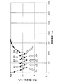
図4は、ガス置換室(室内体積=700リットル,リークによる圧力上昇は1秒間で1.0Pa)に対し、減圧及び増圧を繰り返したガス置換室の気圧(真空圧)と経過時間との関係を示すグラフである。これによると、始めに大気圧(≒101kPa)であったガス置換室の真空圧が、減圧D1~D5、及び、アルゴンガスの導入による増圧R1~R4を繰り返すことによって、気圧が変化することが確認される。特に、本発明の置換方法の場合、大気圧まで復圧させるものではなく、減圧時の第一真空圧よりも高く、かつ大気圧よりも低い第二真空圧までにアルゴンガスの導入を抑えることが行われる。これにより、アルゴンガスの使用量を抑えることができる。
実施例1は、減圧及び増圧の処理を四回繰り返したもの、及び、実施例2は当該処理を五回繰り返したものである。このとき、減圧時の真空圧(第一真空圧)は、いずれも4300Paに設定し、増圧時の真空圧(第二真空圧)は、いずれも14000Paに設定している。一方、比較例1は、従来の不活性ガスの置換方法の通り、減圧及び大気圧までの100%復圧を二回繰り返したもの、比較例2は、高真空まで到達可能な真空ポンプを用い、1度に100Paまで減圧し、その後大気圧まで100%復圧を行ったものである。比較例3は、実施例1及び実施例2と同様に、4300Paまで減圧し、14000Paまで増圧する処理を三回繰り返したものを示している。なお、アルゴンガス使用量の比率は、比較例1の使用量を100%としてその割合を示している。
図6は、アルゴンガス使用量を従来比で30%削減することを想定して行った実験の結果を示している。なお、比較例1及び比較例2は、先に示した図5と同一のものである。一方、実施例3~5は、減圧及び増圧の処理を三回、四回、及び五回それぞれ行ったものである。ここで、実施例3の増圧時の第二真空圧は、24000Paであり、実施例4の増圧時の第二真空圧は、17500Paであり、実施例5の増圧時の第二真空圧は、14000Paである。
Claims (15)
- セラミック体を閉鎖空間に収容し、前記閉鎖空間を外部との気密性を保った状態で閉鎖する閉鎖工程と、
前記閉鎖空間を予め設定された第一真空圧まで減圧する減圧工程と、
減圧された前記閉鎖空間に不活性ガスを導入し、前記第一真空圧より高く、かつ大気圧より低い第二真空圧まで前記閉鎖空間を増圧する増圧工程と、
増圧された前記閉鎖空間を前記第一真空圧まで再減圧する再減圧工程と、
前記増圧工程及び前記再減圧工程を少なくとも二回繰り返した後、前記第一真空圧まで再減圧された前記閉鎖空間に前記不活性ガスを導入し、大気圧まで前記閉鎖空間を復圧する復圧工程と
を具備する不活性ガスの置換方法。 - 前記増圧工程及び前記再減圧工程を四回繰り返す請求項1に記載の不活性ガスの置換方法。
- 前記閉鎖空間は、
前記セラミック体を焼成処理する焼成炉の上流側及び下流側の少なくともいずれか一方の炉開口部と接続されたガス置換室の室内空間であり、
前記ガス置換室及び前記焼成炉の炉開口部の間に、前記閉鎖空間と前記焼成炉の炉内空間とを気密性を保った状態で閉鎖可能な気密シャッタが設置されている請求項1または2に記載の不活性ガスの置換方法。 - 前記閉鎖空間は、
前記セラミック体を焼成処理する焼成炉の炉内空間であり、
前記焼成炉の炉開口部に気密シャッタが設置されている請求項1または2に記載の不活性ガスの置換方法。 - 前記第二真空圧は、
少なくとも二回繰り返されるそれぞれの前記増圧工程で前記真空圧が一定となるように調整され、或いは、前記増圧工程を実施する度に前記真空圧が高くなるように調整される請求項1~4のいずれか一項に記載の不活性ガスの置換方法。 - 前記不活性ガスは、
アルゴンガスが用いられる請求項1~5のいずれか一項に記載の不活性ガスの置換方法。 - 前記セラミック体は、
一方の端面から他方の端面まで延びる複数のセルを区画形成する格子状の隔壁及び外周壁を有する、ハニカム成形体である請求項1~6のいずれか一項に記載の不活性ガスの置換方法。 - 前記復圧工程によって前記大気圧まで復圧される前記閉鎖空間の酸素濃度は、
500ppm以下である請求項1~7のいずれか一項に記載の不活性ガスの置換方法。 - 前記第一真空圧は、
0.1~5kPaの範囲に調整され、
前記第二真空圧は、
12~50kPaの範囲に調整される請求項1~8のいずれか一項に記載の不活性ガスの置換方法。 - 前記閉鎖空間のリークによる圧力上昇が1秒間で1.0Pa以下である請求項1~9のいずれか一項に記載の不活性ガスの置換方法。
- 成形材料からセラミック体を形成する成形工程と、
前記成形工程によって得られた前記セラミック体を焼成し、セラミック構造体を形成する焼成工程と
を具備し、
前記焼成工程は、
前記セラミック体を閉鎖空間に収容し、前記閉鎖空間を外部との気密性を保った状態で閉鎖する閉鎖工程、前記閉鎖空間を予め設定された第一真空圧まで減圧する減圧工程、減圧された前記閉鎖空間に不活性ガスを導入し、前記第一真空圧より高く、かつ大気圧より低い第二真空圧まで前記閉鎖空間を増圧する増圧工程、増圧された前記閉鎖空間を前記第一真空圧まで再減圧する再減圧工程、及び、前記増圧工程及び前記再減圧工程を少なくとも二回繰り返した後、前記第一真空圧まで再減圧された前記閉鎖空間に前記不活性ガスを導入し、大気圧まで前記閉鎖空間を復圧する復圧工程を備える不活性ガスの置換方法を用いたセラミック構造体の製造方法。 - 前記焼成工程における前記不活性ガスの置換方法は、
前記増圧工程及び前記再減圧工程を四回繰り返す請求項11に記載の不活性ガスの置換方法を用いたセラミック構造体の製造方法。 - 前記焼成工程における前記不活性ガスの置換方法は、
前記第二真空圧を少なくとも二回繰り返されるそれぞれの前記増圧工程で前記真空圧が一定となるように調整し、或いは、前記増圧工程を実施する度に前記真空圧が高くなるように調整する請求項11または12に記載の不活性ガスの置換方法を用いたセラミック構造体の製造方法。 - 前記セラミック体は、
一方の端面から他方の端面まで延びる複数のセルを区画形成する格子状の隔壁及び外周壁を有する、ハニカム成形体である請求項11~13のいずれか一項に記載の不活性ガスの置換方法を用いたセラミック構造体の製造方法。 - 前記セラミック体は、
炭化珪素を主成分として含む請求項14に記載の不活性ガスの置換方法を用いたセラミック構造体の製造方法。
Priority Applications (4)
| Application Number | Priority Date | Filing Date | Title |
|---|---|---|---|
| JP2017552718A JP6622323B2 (ja) | 2015-11-25 | 2016-11-25 | 不活性ガスの置換方法、及び不活性ガスの置換方法を用いたセラミック構造体の製造方法 |
| DE112016005398.3T DE112016005398T5 (de) | 2015-11-25 | 2016-11-25 | Inertgasaustauschverfahren und Verfahren zur Herstellung einer Keramikstruktur unter Anwendung des Inertgasaustauschverfahrens |
| CN201680067937.8A CN108290796B (zh) | 2015-11-25 | 2016-11-25 | 非活性气体的置换方法以及使用非活性气体的置换方法的陶瓷结构体的制造方法 |
| US15/969,052 US10774009B2 (en) | 2015-11-25 | 2018-05-02 | Inert gas substituting method and ceramic structure manufacturing method using inert gas substituting method |
Applications Claiming Priority (2)
| Application Number | Priority Date | Filing Date | Title |
|---|---|---|---|
| JP2015-229499 | 2015-11-25 | ||
| JP2015229499 | 2015-11-25 |
Related Child Applications (1)
| Application Number | Title | Priority Date | Filing Date |
|---|---|---|---|
| US15/969,052 Continuation US10774009B2 (en) | 2015-11-25 | 2018-05-02 | Inert gas substituting method and ceramic structure manufacturing method using inert gas substituting method |
Publications (1)
| Publication Number | Publication Date |
|---|---|
| WO2017090718A1 true WO2017090718A1 (ja) | 2017-06-01 |
Family
ID=58763522
Family Applications (1)
| Application Number | Title | Priority Date | Filing Date |
|---|---|---|---|
| PCT/JP2016/084943 Ceased WO2017090718A1 (ja) | 2015-11-25 | 2016-11-25 | 不活性ガスの置換方法、及び不活性ガスの置換方法を用いたセラミック構造体の製造方法 |
Country Status (5)
| Country | Link |
|---|---|
| US (1) | US10774009B2 (ja) |
| JP (1) | JP6622323B2 (ja) |
| CN (1) | CN108290796B (ja) |
| DE (1) | DE112016005398T5 (ja) |
| WO (1) | WO2017090718A1 (ja) |
Cited By (1)
| Publication number | Priority date | Publication date | Assignee | Title |
|---|---|---|---|---|
| JP2020164353A (ja) * | 2019-03-28 | 2020-10-08 | 日本碍子株式会社 | 炭化珪素含有セラミックス製品の製造方法 |
Citations (3)
| Publication number | Priority date | Publication date | Assignee | Title |
|---|---|---|---|---|
| JPS6065766A (ja) * | 1983-09-21 | 1985-04-15 | 株式会社クボタ | 窒化けい素系セラミツクの焼結法 |
| JP2002256306A (ja) * | 2001-03-01 | 2002-09-11 | Matsushita Electric Ind Co Ltd | 粉末の成形方法 |
| JP2007238409A (ja) * | 2006-03-10 | 2007-09-20 | Asahi Glass Co Ltd | 窒化ケイ素フィルタの製造法 |
Family Cites Families (10)
| Publication number | Priority date | Publication date | Assignee | Title |
|---|---|---|---|---|
| JP4574051B2 (ja) | 2001-04-17 | 2010-11-04 | 株式会社ジェイテクト | 熱処理方法及びそれに用いる熱処理装置 |
| US8741800B2 (en) * | 2010-07-22 | 2014-06-03 | Uchicago Argonne, Llc | Hydrothermal performance of catalyst supports |
| CN101941681B (zh) * | 2010-08-24 | 2012-03-28 | 浙江大学 | 制备带隙单调连续变化的硫硒化镉纳米材料的方法及装置 |
| ITMI20110401A1 (it) * | 2011-03-14 | 2012-09-15 | Petroceramics S P A | Metodo per l'infiltrazione di un materiale poroso con un secondo materiale e relativo impianto |
| CN102503423A (zh) * | 2011-11-22 | 2012-06-20 | 东华大学 | 一种SiBNC块状陶瓷的制备方法 |
| CN104072183B (zh) * | 2014-07-09 | 2015-08-19 | 中南林业科技大学 | 一种用碳纤维增强层状木材陶瓷的方法 |
| US9776930B2 (en) * | 2014-08-27 | 2017-10-03 | King Abdulaziz City For Science And Technology | Nano-porous corundum ceramics and methods of manufacture |
| US9527774B2 (en) * | 2014-08-27 | 2016-12-27 | King Abdulaziz City For Science And Technology | High strength transparent ceramic using corundum powder and methods of manufacture |
| CN104828825B (zh) * | 2015-05-19 | 2017-12-05 | 山东大学 | 一种低成本低温合成碳化硅粉料的方法 |
| US20160370116A1 (en) * | 2015-06-19 | 2016-12-22 | Apple Inc. | Process for heat treating a sapphire component |
-
2016
- 2016-11-25 CN CN201680067937.8A patent/CN108290796B/zh active Active
- 2016-11-25 DE DE112016005398.3T patent/DE112016005398T5/de active Pending
- 2016-11-25 WO PCT/JP2016/084943 patent/WO2017090718A1/ja not_active Ceased
- 2016-11-25 JP JP2017552718A patent/JP6622323B2/ja active Active
-
2018
- 2018-05-02 US US15/969,052 patent/US10774009B2/en active Active
Patent Citations (3)
| Publication number | Priority date | Publication date | Assignee | Title |
|---|---|---|---|---|
| JPS6065766A (ja) * | 1983-09-21 | 1985-04-15 | 株式会社クボタ | 窒化けい素系セラミツクの焼結法 |
| JP2002256306A (ja) * | 2001-03-01 | 2002-09-11 | Matsushita Electric Ind Co Ltd | 粉末の成形方法 |
| JP2007238409A (ja) * | 2006-03-10 | 2007-09-20 | Asahi Glass Co Ltd | 窒化ケイ素フィルタの製造法 |
Cited By (2)
| Publication number | Priority date | Publication date | Assignee | Title |
|---|---|---|---|---|
| JP2020164353A (ja) * | 2019-03-28 | 2020-10-08 | 日本碍子株式会社 | 炭化珪素含有セラミックス製品の製造方法 |
| JP7249848B2 (ja) | 2019-03-28 | 2023-03-31 | 日本碍子株式会社 | 炭化珪素含有セラミックス製品の製造方法 |
Also Published As
| Publication number | Publication date |
|---|---|
| CN108290796B (zh) | 2020-08-28 |
| US20180244584A1 (en) | 2018-08-30 |
| JP6622323B2 (ja) | 2019-12-18 |
| JPWO2017090718A1 (ja) | 2018-09-20 |
| DE112016005398T5 (de) | 2018-08-09 |
| CN108290796A (zh) | 2018-07-17 |
| US10774009B2 (en) | 2020-09-15 |
Similar Documents
| Publication | Publication Date | Title |
|---|---|---|
| US12553667B2 (en) | Method for manufacturing ceramic product containing silicon carbide | |
| EP1647790B1 (en) | Method of manufacturing porous ceramic body | |
| EP3024798B1 (en) | Fast firing method for high porosity ceramics | |
| CN101500682B (zh) | 堇青石质陶瓷蜂窝过滤器的制造方法 | |
| CN110041082B (zh) | 陶瓷烧成体的制造方法、以及陶瓷成型体的烧成方法 | |
| JP6622323B2 (ja) | 不活性ガスの置換方法、及び不活性ガスの置換方法を用いたセラミック構造体の製造方法 | |
| KR102025609B1 (ko) | 전자부품 제조용 가스 오븐 | |
| US11034624B2 (en) | Manufacturing method of silicon carbide-based honeycomb structure | |
| JP5546654B2 (ja) | 基板処理装置、半導体製造方法、基板処理方法、及び異物除去方法 | |
| WO2013136916A1 (ja) | ロードロック装置 | |
| CN114107958A (zh) | 基板处理方法及其基板处理装置、半导体器件制造方法 | |
| JP5597433B2 (ja) | 真空処理装置 | |
| JP5339029B2 (ja) | 焼成炉制御方法及び焼成装置 | |
| US20180085799A1 (en) | Exhaust system, semiconductor manufacturing equipment, and method for operating the exhaust system | |
| US20220016700A1 (en) | Two-stage sintering furnace and methods of operating thereof | |
| CN109708478B (zh) | 气氛置换方法及装置和附带气氛置换装置的烧成炉 | |
| TWI786999B (zh) | 腔室內部處理方法及基板處理方法 | |
| JP2014143421A (ja) | 基板処理装置、半導体製造方法、基板処理方法 | |
| JP2010228966A (ja) | Si結合SiCセラミックスの焼成方法 | |
| WO2002052638A1 (fr) | Procede de regulation de pression, dispositif de transfert, et outil en grappe | |
| CN121021162A (zh) | 一种改善氧化铝陶瓷盘平整度的热处理方法 | |
| JP2024114289A (ja) | ガラス母材の製造装置および製造方法 | |
| CN119638379A (zh) | 一种提高高纯氧化铝静电卡盘排胶率的方法 | |
| KR19990079578A (ko) | 반도체 제조장비의 공정챔버 정화방법 | |
| JP2007187396A (ja) | 焼成装置 |
Legal Events
| Date | Code | Title | Description |
|---|---|---|---|
| 121 | Ep: the epo has been informed by wipo that ep was designated in this application |
Ref document number: 16868661 Country of ref document: EP Kind code of ref document: A1 |
|
| ENP | Entry into the national phase |
Ref document number: 2017552718 Country of ref document: JP Kind code of ref document: A |
|
| WWE | Wipo information: entry into national phase |
Ref document number: 112016005398 Country of ref document: DE |
|
| 122 | Ep: pct application non-entry in european phase |
Ref document number: 16868661 Country of ref document: EP Kind code of ref document: A1 |