WO2017088263A1 - 一种穿刺规划路径纠正方法及装置 - Google Patents
一种穿刺规划路径纠正方法及装置 Download PDFInfo
- Publication number
- WO2017088263A1 WO2017088263A1 PCT/CN2015/099650 CN2015099650W WO2017088263A1 WO 2017088263 A1 WO2017088263 A1 WO 2017088263A1 CN 2015099650 W CN2015099650 W CN 2015099650W WO 2017088263 A1 WO2017088263 A1 WO 2017088263A1
- Authority
- WO
- WIPO (PCT)
- Prior art keywords
- initial
- image
- point
- planning path
- puncture
- Prior art date
- Legal status (The legal status is an assumption and is not a legal conclusion. Google has not performed a legal analysis and makes no representation as to the accuracy of the status listed.)
- Ceased
Links
Images




Classifications
-
- A—HUMAN NECESSITIES
- A61—MEDICAL OR VETERINARY SCIENCE; HYGIENE
- A61B—DIAGNOSIS; SURGERY; IDENTIFICATION
- A61B17/00—Surgical instruments, devices or methods
- A61B17/34—Trocars; Puncturing needles
-
- A—HUMAN NECESSITIES
- A61—MEDICAL OR VETERINARY SCIENCE; HYGIENE
- A61B—DIAGNOSIS; SURGERY; IDENTIFICATION
- A61B34/00—Computer-aided surgery; Manipulators or robots specially adapted for use in surgery
- A61B34/10—Computer-aided planning, simulation or modelling of surgical operations
Definitions
- the present invention relates to the field of biomedical image technology, and in particular, to a method and apparatus for correcting a puncture planning path.
- TPE tip position error
- the component along the direction of the puncture needle body is the radial component of the TPE
- the component perpendicular to the direction of the puncture needle body is the transverse component of the TPE.
- the lateral component of TPE is the most important. If the lateral component is too large, it must be re-pierced to correct the offset. Otherwise, only the insertion depth of the puncture needle needs to be adjusted to offset the error of the radial component of the TPE.
- Navigation error TPE calculation often needs to pass CT after the puncture and locate the position of the tumor and the position of the needle in the CT image, calculate the distance between the two to determine the size of the TPE and its lateral and radial components. If the navigation error is large, especially when the lateral component of the TPE is large, the puncture failure can be found after the first puncture, and then a second puncture must be performed to correct the navigation deviation. Multiple punctures will inevitably increase the chance of complications, and doctors rely on experience to make navigational deviation corrections will introduce large manual errors, and can not completely eliminate navigation bias. Therefore, in the case of large navigation error, a method for quantifying navigation error before puncture and automatic error correction is needed, which is used to improve the puncture navigation accuracy and reduce the navigation error, especially the TPE lateral component error.
- the navigation error cannot be predicted before the puncture. Only after the first puncture, the doctor can correct the navigation deviation according to the postoperative CT estimation error and rely on experience, and then do the second puncture.
- the present invention proposes a puncture planning path correction method and device, which can predict the navigation error without puncture, and correct the planning path according to the navigation deviation, and finally follow the corrected planning path. Puncture can greatly improve navigation accuracy.
- the present invention provides a method for correcting a puncture planning path, including:
- Marking an initial planning path on the initial CT image ; acquiring location information of the marking point in the second CT image;
- the initial planned path is translated by using the distance vector of the marked point to the initial planning path, and the intersection of the transformed path and the skin of the puncture area is determined as the actual entry point. And determining a target point according to the length of the initial planning path according to the actual entry point, and obtaining a corrected puncture planning path.
- the present invention also provides a puncture planning path correction device, comprising:
- a marking point determining unit configured to determine an initial entry point on the skin of the puncture area according to the initial planning path, and set the initial entry point as a marking point;
- a CT scanning unit is configured to perform two CT scans on the puncture area in sequence to obtain an initial CT image and a second CT image;
- An initializing unit configured to mark an initial planning path on the initial CT image; and acquire location information of the marked point in the second CT image;
- a registration unit configured to register the initial CT image and the second CT image, and determine a position of the marker point in an initial CT image after registration according to position information of the marker point;
- a translation vector acquisition unit configured to obtain a distance vector of the marker point to the initial planning path
- a correcting unit configured to perform a translation transformation on the initial planning path by using a distance vector of the marked point to the initial planning path in an initial CT image after registration, and an intersection of the transformed path and the skin of the puncture area
- the actual entry point is determined, and according to the actual entry point, the target point is determined according to the length of the initial planned path, and the corrected puncture planning path is obtained.
- the technical solution can quantify the navigation error without puncture, and correct the initial planning path according to the navigation error, and the navigation offset correction by the doctor is more accurate and intuitive.
- the technical solution is simple and versatile, and can be applied to various kinds of puncture navigation systems.
- Figure 1 is a schematic diagram of the decomposition of the puncture navigation error TPE
- FIG. 2 is a flow chart of a method for correcting a puncture planning path according to the present invention
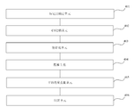
- FIG. 4 is a block diagram of a puncture planning path correction device provided by the present invention.
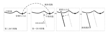
- Figure 5 is a schematic diagram of a puncture planning path correction process
- FIG. 6 is a functional block diagram of a registration unit in a puncture planning path correction device
- Figure 7b is a schematic view showing the result of puncture according to the initial planned route of the embodiment.
- Figure 7c is a schematic diagram of the route after correction according to the embodiment.
- Fig. 7d is a schematic view showing the result of puncture according to the corrected route of the embodiment.
- the working principle of the technical scheme At present, most of the research on the correction of the puncture navigation error stays on the navigation error quantification, and does not propose a substantial solution to the error correction, and mainly when the navigation error is found after the puncture is large, the doctor according to the Experience corrects the navigation deviation and makes a second puncture.
- the technical solution solves the problem of quantifying the navigation error before puncture, and corrects the planning path according to the quantized error, so that the navigation error can be corrected before the puncture, so that the precise planning path is corrected according to the revised planning path. Doctor puncture.
- the technical solution is an automatic correction method for the planning path, which is used for improving the precision of the puncture navigation.
- the present invention proposes a puncture planning path correction method, as shown in FIG. 2 .
- a puncture planning path correction method as shown in FIG. 2 .
- Step 201) determining an initial entry point on the skin of the puncture area according to the initial planning path, and setting the initial entry point as a mark point;
- step 201 step 202, step 203, before the puncture navigation starts, the entry point is found on the patient according to the initial planning path, and the marker point is pasted here, then the patient is subjected to a second CT scan, and finally from the second The position information of the marker points is manually extracted in the CT image.
- step 204 and step 205 first, registration is performed between the initial CT image and the second CT image, and then the marker points in the second CT image are transformed into the initial CT image.
- the CT image registration is realized by using the marker points for rigid body registration, that is, selecting a plurality of corresponding anatomical landmark points in the vicinity of the marker points in the two images to perform rigid body matching.
- Rigid body registration or rigid body matching refers to the registration between two images by rigid body transformation.
- the present invention transforms the second CT image into the initial CT image space by using rigid body transformation, and each pixel in the transformed second CT image.
- the relative distance between the points does not change in the initial CT image, that is, the overall topology does not change after the second CT image is transformed.
- the distance vector from the marker point to the initial planning path is then calculated in the initial CT image, ie the translation vector to eliminate the navigation error.
- FIG. 3 it is a schematic diagram for quantifying the TPE lateral component error.
- the size of the translation vector is equal to the magnitude of the lateral component of the navigation error TPE, and the application of the translation vector to the initial path can effectively reduce the lateral component error of the TPE, thereby greatly improving the navigation accuracy.
- the target point is determined according to the length of the initial planned path, and the corrected puncture planning path is obtained.
- step 206 after the navigation error (TPE lateral error) is quantized, the initial translation path is translated by using the obtained translation vector, and a new entry point is searched on the skin of the puncture area according to the transformed path, and the point is after translation.
- the path entry point once the entry point is determined, the target of the new path can be determined according to the length of the initial planned path, and finally the corrected puncture planning path is obtained.
- the present invention also provides a puncture planning path correcting device, as shown in FIG.
- the function of each functional module of the puncture planning path correction device will be described with reference to FIG.
- the puncture planning path correction device comprises:
- a marker point determining unit 401 configured to determine an initial entry point on the skin of the puncture region according to the initial planning path, and set the initial entry point as a marker point;
- the CT scanning unit 402 is configured to perform two CT scans on the puncture area in sequence to obtain an initial CT image and a second CT image;
- An initializing unit 403, configured to mark an initial planning path on the initial CT image, and acquire location information of the marked point in the second CT image;
- a registration unit 404 configured to register the initial CT image and the second CT image, and determine a position of the marker point in an initial CT image after registration according to position information of the marker point ;
- a translation vector obtaining unit 405, configured to obtain a distance vector of the marked point to the initial planning path
- a correcting unit 406 configured to perform a translation transformation on the initial planned path by using a distance vector of the marked point to the initial planning path in an initial CT image after registration, and the transformed path and the skin of the puncture area Pay
- the point is determined as an actual entry point, and according to the actual entry point, the target point is determined according to the length of the initial planned path, and the corrected puncture planning path is obtained.
- the registration unit 404 includes:
- An anatomical landmark point determining module 4041 configured to determine a plurality of anatomical landmarks in regions near the marked points in the two CT images, respectively;
- the rigid body matching module 4042 is configured to match the anatomical landmarks of the initial CT image with the anatomical landmarks of the second CT image.
- FIGs 7a to 7d show that the dark lines are the initial planning paths.
- Figure 7b shows the results of the puncture according to the initial planning path shown in Figure 7a.
- the black globules are tumor targets.
- Figure 7c the dark lines are the initial planning paths and the light lines are the corrected paths.
- Figure 7d shows the results of puncture according to the corrected path.
Landscapes
- Health & Medical Sciences (AREA)
- Surgery (AREA)
- Life Sciences & Earth Sciences (AREA)
- Engineering & Computer Science (AREA)
- Medical Informatics (AREA)
- Biomedical Technology (AREA)
- Heart & Thoracic Surgery (AREA)
- Nuclear Medicine, Radiotherapy & Molecular Imaging (AREA)
- Molecular Biology (AREA)
- Animal Behavior & Ethology (AREA)
- General Health & Medical Sciences (AREA)
- Public Health (AREA)
- Veterinary Medicine (AREA)
- Robotics (AREA)
- Pathology (AREA)
- Apparatus For Radiation Diagnosis (AREA)
Abstract
Description
Claims (6)
- 一种穿刺规划路径纠正方法,其特征在于,包括:根据初始规划路径,在穿刺区域表皮上确定初始入口点,并将所述初始入口点设置为标记点;对穿刺区域先后进行两次CT扫描,获得初始CT图像和第二CT图像;在所述初始CT图像上标出初始规划路径;在所述第二CT图像中获取所述标记点的位置信息;将所述初始CT图像和所述第二CT图像进行配准;并根据所述标记点的位置信息,确定所述标记点在配准之后的初始CT图像中的位置;获得所述标记点到所述初始规划路径的距离向量;在配准之后的初始CT图像中,利用所述标记点到所述初始规划路径的距离向量,对所述初始规划路径做平移变换,变换后的路径与穿刺区域表皮的交点定为实际入口点,根据所述实际入口点,按照所述初始规划路径的长度确定靶点,获得纠正后的穿刺规划路径。
- 如权利要求1所述的方法,其特征在于,所述配准的步骤包括:分别在两幅CT图像中的标记点附近区域确定多个解剖结构标志点;将所述初始CT图像的解剖结构标志点对应的与所述第二CT图像的解剖结构标志点做刚体匹配。
- 如权利要求1所述的方法,其特征在于,所述距离向量的大小与导航误差的横向分量的大小相等。
- 一种穿刺规划路径纠正装置,其特征在于,包括:标记点确定单元,用于根据初始规划路径,在穿刺区域表皮上确定初始入口点,并将所述初始入口点设置为标记点;CT扫描单元,用于对穿刺区域先后进行两次CT扫描,获得初始CT图像和第二CT图像;初始化单元,用于在所述初始CT图像上标出初始规划路径;在所述第二CT图像中获取所述标记点的位置信息;配准单元,用于将所述初始CT图像和所述第二CT图像进行配准,并根据所述标记点的位置信息,确定所述标记点在配准之后的初始CT图像中的位置;平移向量获取单元,用于获得所述标记点到所述初始规划路径的距离向量;纠正单元,用于在配准之后的初始CT图像中,利用所述标记点到所述初始规划路径的距离向量,对所述初始规划路径做平移变换,变换后的路径与穿刺区域表皮的交点定为实际入口点,根据所述实际入口点,按照所述初始规划路径的长度确定靶点,获得纠正后的穿刺规划路径。
- 如权利要求4所述的装置,其特征在于,所述配准单元包括:解剖结构标志点确定模块,用于分别在两幅CT图像中的标记点附近区域确定多个解剖结构标志点;刚体匹配模块,用于将所述初始CT图像的解剖结构标志点对应的与所述第二CT图像的解剖结构标志点做刚体匹配。
- 如权利要求4所述的装置,其特征在于,所述平移向量获取单元获得的距离向量的大小与导航误差的横向分量的大小相等。
Applications Claiming Priority (2)
| Application Number | Priority Date | Filing Date | Title |
|---|---|---|---|
| CN201510816046.5 | 2015-11-23 | ||
| CN201510816046.5A CN105411679B (zh) | 2015-11-23 | 2015-11-23 | 一种穿刺规划路径纠正方法及装置 |
Publications (1)
| Publication Number | Publication Date |
|---|---|
| WO2017088263A1 true WO2017088263A1 (zh) | 2017-06-01 |
Family
ID=55490547
Family Applications (1)
| Application Number | Title | Priority Date | Filing Date |
|---|---|---|---|
| PCT/CN2015/099650 Ceased WO2017088263A1 (zh) | 2015-11-23 | 2015-12-30 | 一种穿刺规划路径纠正方法及装置 |
Country Status (2)
| Country | Link |
|---|---|
| CN (1) | CN105411679B (zh) |
| WO (1) | WO2017088263A1 (zh) |
Cited By (5)
| Publication number | Priority date | Publication date | Assignee | Title |
|---|---|---|---|---|
| CN113413189A (zh) * | 2019-04-12 | 2021-09-21 | 北京诺亦腾科技有限公司 | 一种基于虚拟现实技术的打孔控制方法 |
| CN114454172A (zh) * | 2020-09-25 | 2022-05-10 | 武汉联影智融医疗科技有限公司 | 机械臂的末端适配器的控制方法 |
| CN115120348A (zh) * | 2021-03-24 | 2022-09-30 | 上海微创医疗机器人(集团)股份有限公司 | 一种计算机可读存储介质、电子设备及手术机器人系统 |
| CN116531093A (zh) * | 2023-05-08 | 2023-08-04 | 深圳惟德精准医疗科技有限公司 | 穿刺导航系统的精度检测方法及相关产品 |
| CN118141516A (zh) * | 2024-05-09 | 2024-06-07 | 南开大学 | 一种脑穿刺路径规划方法及装置 |
Families Citing this family (11)
| Publication number | Priority date | Publication date | Assignee | Title |
|---|---|---|---|---|
| CN106021935B (zh) * | 2016-05-24 | 2018-09-28 | 深圳先进技术研究院 | 一种柔性针穿刺路径评估方法及系统 |
| CN106137394B (zh) * | 2016-06-15 | 2019-09-24 | 苏州铸正机器人有限公司 | 一种获取椎弓根标准轴位图的方法 |
| CN106236258B (zh) * | 2016-08-17 | 2019-03-12 | 北京柏惠维康科技有限公司 | 腹腔微创手术穿刺路径的规划方法及装置 |
| EP3566669B1 (en) * | 2018-05-10 | 2026-03-18 | Globus Medical, Inc. | Method for defining the position of a surgical implant device relative to a bone |
| CN109893247B (zh) * | 2019-04-11 | 2021-01-01 | 艾瑞迈迪科技石家庄有限公司 | 手术器械操作路径的导航及显示方法、装置 |
| CN110123447A (zh) * | 2019-05-07 | 2019-08-16 | 艾瑞迈迪科技石家庄有限公司 | 应用于影像引导的引导路径规划方法及装置 |
| CN115137453A (zh) * | 2019-07-05 | 2022-10-04 | 湖南卓世创思科技有限公司 | 一种连续扫描截面升维空间定位系统 |
| EP4218649A4 (en) | 2020-09-25 | 2024-10-23 | Wuhan United Imaging Healthcare Surgical Technology Co., Ltd. | SURGICAL ROBOT CONTROL METHOD, COMPUTER DEVICE AND SURGICAL ROBOT SYSTEM |
| CN112932546A (zh) * | 2021-01-26 | 2021-06-11 | 溥熵微创医疗科技(辽宁)有限公司 | 一种基于视觉分析的咽拭子采样方法 |
| CN115956988B (zh) * | 2023-01-20 | 2026-02-03 | 深圳市箴石医疗设备有限公司 | 一种穿刺手术监控方法、装置及存储介质 |
| CN116725670A (zh) * | 2023-06-13 | 2023-09-12 | 深圳惟德精准医疗科技有限公司 | 穿刺导航系统的精度检测方法及相关产品 |
Citations (5)
| Publication number | Priority date | Publication date | Assignee | Title |
|---|---|---|---|---|
| CN102920510A (zh) * | 2012-10-29 | 2013-02-13 | 清华大学 | 柔性穿刺针的路径规划方法 |
| CN102961187A (zh) * | 2012-10-26 | 2013-03-13 | 深圳市旭东数字医学影像技术有限公司 | 经皮穿刺的手术规划方法及其系统 |
| CN103181764A (zh) * | 2011-12-30 | 2013-07-03 | 上海爱立峰医疗科技有限公司 | 磁共振扫描定位系统及指向性定位扫描方法 |
| JP2013220132A (ja) * | 2012-04-13 | 2013-10-28 | Ge Medical Systems Global Technology Co Llc | 穿刺計画支援装置、医用画像装置及び超音波診断装置 |
| CN105054999A (zh) * | 2015-08-18 | 2015-11-18 | 浙江工业大学 | 一种改进的颅内穿刺导向方法及装置 |
Family Cites Families (5)
| Publication number | Priority date | Publication date | Assignee | Title |
|---|---|---|---|---|
| CN100493471C (zh) * | 2006-01-26 | 2009-06-03 | 清华大学深圳研究生院 | 计算机辅助经皮肾穿刺取石术中的穿刺导航系统 |
| CN101564289A (zh) * | 2009-06-03 | 2009-10-28 | 南京航空航天大学 | 基于近红外光谱的神经外科导航穿刺路径实时纠错方法 |
| JP6120497B2 (ja) * | 2012-06-26 | 2017-04-26 | キヤノン株式会社 | 穿刺制御装置及び方法 |
| CN102999902B (zh) * | 2012-11-13 | 2016-12-21 | 上海交通大学医学院附属瑞金医院 | 基于ct配准结果的光学导航定位导航方法 |
| CN103892912B (zh) * | 2012-12-27 | 2016-06-01 | 上海西门子医疗器械有限公司 | X线辅助的穿刺定位方法及系统 |
-
2015
- 2015-11-23 CN CN201510816046.5A patent/CN105411679B/zh active Active
- 2015-12-30 WO PCT/CN2015/099650 patent/WO2017088263A1/zh not_active Ceased
Patent Citations (5)
| Publication number | Priority date | Publication date | Assignee | Title |
|---|---|---|---|---|
| CN103181764A (zh) * | 2011-12-30 | 2013-07-03 | 上海爱立峰医疗科技有限公司 | 磁共振扫描定位系统及指向性定位扫描方法 |
| JP2013220132A (ja) * | 2012-04-13 | 2013-10-28 | Ge Medical Systems Global Technology Co Llc | 穿刺計画支援装置、医用画像装置及び超音波診断装置 |
| CN102961187A (zh) * | 2012-10-26 | 2013-03-13 | 深圳市旭东数字医学影像技术有限公司 | 经皮穿刺的手术规划方法及其系统 |
| CN102920510A (zh) * | 2012-10-29 | 2013-02-13 | 清华大学 | 柔性穿刺针的路径规划方法 |
| CN105054999A (zh) * | 2015-08-18 | 2015-11-18 | 浙江工业大学 | 一种改进的颅内穿刺导向方法及装置 |
Cited By (7)
| Publication number | Priority date | Publication date | Assignee | Title |
|---|---|---|---|---|
| CN113413189A (zh) * | 2019-04-12 | 2021-09-21 | 北京诺亦腾科技有限公司 | 一种基于虚拟现实技术的打孔控制方法 |
| CN113413189B (zh) * | 2019-04-12 | 2022-07-19 | 北京诺亦腾科技有限公司 | 一种基于虚拟现实技术的非治疗目的打孔控制方法 |
| CN114454172A (zh) * | 2020-09-25 | 2022-05-10 | 武汉联影智融医疗科技有限公司 | 机械臂的末端适配器的控制方法 |
| CN114454172B (zh) * | 2020-09-25 | 2024-04-23 | 武汉联影智融医疗科技有限公司 | 机械臂的末端适配器的控制方法 |
| CN115120348A (zh) * | 2021-03-24 | 2022-09-30 | 上海微创医疗机器人(集团)股份有限公司 | 一种计算机可读存储介质、电子设备及手术机器人系统 |
| CN116531093A (zh) * | 2023-05-08 | 2023-08-04 | 深圳惟德精准医疗科技有限公司 | 穿刺导航系统的精度检测方法及相关产品 |
| CN118141516A (zh) * | 2024-05-09 | 2024-06-07 | 南开大学 | 一种脑穿刺路径规划方法及装置 |
Also Published As
| Publication number | Publication date |
|---|---|
| CN105411679A (zh) | 2016-03-23 |
| CN105411679B (zh) | 2017-07-14 |
Similar Documents
| Publication | Publication Date | Title |
|---|---|---|
| WO2017088263A1 (zh) | 一种穿刺规划路径纠正方法及装置 | |
| US10706540B2 (en) | Fluoroscopic pose estimation | |
| CN104434313B (zh) | 一种腹部外科手术导航方法及系统 | |
| CN100493471C (zh) | 计算机辅助经皮肾穿刺取石术中的穿刺导航系统 | |
| CN101449292B (zh) | 坐标系配准 | |
| US10307079B2 (en) | Method and system for surgical instrument guidance and tracking with position and orientation correction | |
| US8781186B2 (en) | System and method for abdominal surface matching using pseudo-features | |
| CN110946654A (zh) | 一种基于多模影像融合的骨科手术导航系统 | |
| US20190374290A1 (en) | System and methods for navigating interventional instrumentation | |
| US11364179B2 (en) | Insertion device positioning guidance system and method | |
| US20100179418A1 (en) | Instrument aligning method using a free reference | |
| CN109620303B (zh) | 一种肺部辅助诊断方法及装置 | |
| EP3255609A1 (en) | A method of automatically identifying a sequence of marking points in 3d medical image | |
| EP3323370A2 (en) | Electromagnetic navigation registration using ultrasound | |
| CN116327362B (zh) | 磁探头辅助支气管术中导航方法、装置、介质及电子设备 | |
| CN114176779B (zh) | 一种手术机器人导航定位方法及装置 | |
| CN113952029A (zh) | 一种实时步进式经皮穿刺规划系统 | |
| CN106236264B (zh) | 基于光学跟踪和图像匹配的胃肠手术导航方法及系统 | |
| CN105232161A (zh) | 一种手术机器人标志点识别定位方法 | |
| CN111121805A (zh) | 基于道路交通标线标志的局部定位修正方法、设备及介质 | |
| US20090171197A1 (en) | Surgical Instrument Calibration | |
| US9514384B2 (en) | Image display apparatus, image display method and storage medium storing image display program | |
| CN120814905A (zh) | 基于前列腺多模态成像的穿刺规划方法、系统及存储介质 | |
| CN105534596B (zh) | 一种用于双目光学探头与b超探头之间空间位置校准的方法及靶线体模 | |
| CN117100397A (zh) | 一种手术导航定位系统的配准方法及其系统 |
Legal Events
| Date | Code | Title | Description |
|---|---|---|---|
| 121 | Ep: the epo has been informed by wipo that ep was designated in this application |
Ref document number: 15909174 Country of ref document: EP Kind code of ref document: A1 |
|
| NENP | Non-entry into the national phase |
Ref country code: DE |
|
| 32PN | Ep: public notification in the ep bulletin as address of the adressee cannot be established |
Free format text: NOTING OF LOSS OF RIGHTS PURSUANT TO RULE 112(1) EPC (EPO FORM 1205A DATED 18/09/2018) |
|
| 32PN | Ep: public notification in the ep bulletin as address of the adressee cannot be established |
Free format text: NOTING OF LOSS OF RIGHTS PURSUANT TO RULE 112(1) EPC (EPO FORM 1205A DATED 18.09.2018) |
|
| 122 | Ep: pct application non-entry in european phase |
Ref document number: 15909174 Country of ref document: EP Kind code of ref document: A1 |