WO2017086294A1 - 血圧推定装置、情報処理装置、血圧推定方法、及び、血圧推定プログラム - Google Patents
血圧推定装置、情報処理装置、血圧推定方法、及び、血圧推定プログラム Download PDFInfo
- Publication number
- WO2017086294A1 WO2017086294A1 PCT/JP2016/083770 JP2016083770W WO2017086294A1 WO 2017086294 A1 WO2017086294 A1 WO 2017086294A1 JP 2016083770 W JP2016083770 W JP 2016083770W WO 2017086294 A1 WO2017086294 A1 WO 2017086294A1
- Authority
- WO
- WIPO (PCT)
- Prior art keywords
- blood pressure
- pressure estimation
- time
- estimation device
- parameter
- Prior art date
- Legal status (The legal status is an assumption and is not a legal conclusion. Google has not performed a legal analysis and makes no representation as to the accuracy of the status listed.)
- Ceased
Links
Images







Classifications
-
- A—HUMAN NECESSITIES
- A61—MEDICAL OR VETERINARY SCIENCE; HYGIENE
- A61B—DIAGNOSIS; SURGERY; IDENTIFICATION
- A61B5/00—Measuring for diagnostic purposes; Identification of persons
- A61B5/02—Detecting, measuring or recording for evaluating the cardiovascular system, e.g. pulse, heart rate, blood pressure or blood flow
- A61B5/021—Measuring pressure in heart or blood vessels
- A61B5/02108—Measuring pressure in heart or blood vessels from analysis of pulse wave characteristics
- A61B5/02116—Measuring pressure in heart or blood vessels from analysis of pulse wave characteristics of pulse wave amplitude
-
- A—HUMAN NECESSITIES
- A61—MEDICAL OR VETERINARY SCIENCE; HYGIENE
- A61B—DIAGNOSIS; SURGERY; IDENTIFICATION
- A61B5/00—Measuring for diagnostic purposes; Identification of persons
- A61B5/72—Signal processing specially adapted for physiological signals or for diagnostic purposes
- A61B5/7271—Specific aspects of physiological measurement analysis
- A61B5/7278—Artificial waveform generation or derivation, e.g. synthesizing signals from measured signals
-
- A—HUMAN NECESSITIES
- A61—MEDICAL OR VETERINARY SCIENCE; HYGIENE
- A61B—DIAGNOSIS; SURGERY; IDENTIFICATION
- A61B5/00—Measuring for diagnostic purposes; Identification of persons
- A61B5/02—Detecting, measuring or recording for evaluating the cardiovascular system, e.g. pulse, heart rate, blood pressure or blood flow
- A61B5/024—Measuring pulse rate or heart rate
- A61B5/02416—Measuring pulse rate or heart rate using photoplethysmograph signals, e.g. generated by infrared radiation
-
- A—HUMAN NECESSITIES
- A61—MEDICAL OR VETERINARY SCIENCE; HYGIENE
- A61B—DIAGNOSIS; SURGERY; IDENTIFICATION
- A61B5/00—Measuring for diagnostic purposes; Identification of persons
- A61B5/02—Detecting, measuring or recording for evaluating the cardiovascular system, e.g. pulse, heart rate, blood pressure or blood flow
- A61B5/024—Measuring pulse rate or heart rate
- A61B5/0245—Measuring pulse rate or heart rate by using sensing means generating electric signals, i.e. ECG signals
-
- A—HUMAN NECESSITIES
- A61—MEDICAL OR VETERINARY SCIENCE; HYGIENE
- A61B—DIAGNOSIS; SURGERY; IDENTIFICATION
- A61B5/00—Measuring for diagnostic purposes; Identification of persons
- A61B5/02—Detecting, measuring or recording for evaluating the cardiovascular system, e.g. pulse, heart rate, blood pressure or blood flow
- A61B5/026—Measuring blood flow
- A61B5/0295—Measuring blood flow using plethysmography, i.e. measuring the variations in the volume of a body part as modified by the circulation of blood therethrough, e.g. impedance plethysmography
-
- A—HUMAN NECESSITIES
- A61—MEDICAL OR VETERINARY SCIENCE; HYGIENE
- A61B—DIAGNOSIS; SURGERY; IDENTIFICATION
- A61B5/00—Measuring for diagnostic purposes; Identification of persons
- A61B5/68—Arrangements of detecting, measuring or recording means, e.g. sensors, in relation to patient
- A61B5/6801—Arrangements of detecting, measuring or recording means, e.g. sensors, in relation to patient specially adapted to be attached to or worn on the body surface
- A61B5/6802—Sensor mounted on worn items
- A61B5/681—Wristwatch-type devices
Definitions
- the present invention relates to a blood pressure estimation device, an information processing device, a blood pressure estimation method, and a blood pressure estimation program.
- a blood pressure estimation device that estimates the pressure (in other words, blood pressure) of blood flowing through a living body's circulatory system is known (see, for example, Patent Document 1).
- the blood pressure estimation device detects the arterial diameter at two positions on the surface of the finger and also detects the electrical impedance of the living body between the two positions. Furthermore, the blood pressure estimation device estimates blood pressure based on the detected artery diameter and electrical impedance and the Kalman filter.
- blood pressure may not be estimated with high accuracy.
- One of the objects of the present invention is to estimate blood pressure with high accuracy.
- the blood pressure estimation device includes: A detection unit for detecting a first parameter representing a cycle length that is a length of a heartbeat cycle of a living body; In a mathematical model representing blood flowing in the circulatory system of the living body by a fluid flowing through a flow path in which a plurality of elastically deforming containers are connected in an annular shape, the volume of at least one of the plurality of containers is with respect to time; A processor that determines a change based on the detected first parameter, and that estimates the pressure of the blood based on the determined change and the mathematical model; Is provided.
- the information processing apparatus is Change in volume of at least one of the plurality of containers with respect to time in a mathematical model representing blood flowing through a circulatory system of a living body by a fluid flowing through a flow path in which a plurality of containers that are elastically deformed are annularly connected
- Determining unit based on the first parameter representing the detected cycle length, which is the length of the cycle of the heartbeat of the living body,
- An estimation unit that estimates the pressure of the blood based on the determined change and the mathematical model; Is provided.
- the blood pressure estimation method comprises: Change in volume of at least one of the plurality of containers with respect to time in a mathematical model representing blood flowing through a circulatory system of a living body by a fluid flowing through a flow path in which a plurality of containers that are elastically deformed are annularly connected Is determined based on the first parameter representing the detected cycle length, which is the length of the cycle of the heartbeat of the living body, Based on the determined change and the mathematical model, the pressure of the blood is estimated.
- the blood pressure estimation program includes: Change in volume of at least one of the plurality of containers with respect to time in a mathematical model representing blood flowing through a circulatory system of a living body by a fluid flowing through a flow path in which a plurality of containers that are elastically deformed are annularly connected Is determined based on the first parameter representing the detected cycle length, which is the length of the cycle of the heartbeat of the living body, Based on the determined change and the mathematical model, the computer is caused to execute a process for estimating the pressure of the blood.
- FIGS. 1 to 41 embodiments relating to a blood pressure estimation device, an information processing device, a blood pressure estimation method, and a blood pressure estimation program according to the present invention will be described with reference to FIGS. 1 to 41.
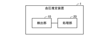
- the blood pressure estimation device 1 includes a detection unit 10 and a processing unit 20.
- the blood pressure estimation device 1 is a wristwatch type.
- the blood pressure estimation device 1 may be a type different from the wristwatch type (for example, a bandage type).
- the detection unit 10 detects a first parameter representing a cycle length that is a cycle length of a heartbeat (in other words, a pulse) of a living body.
- the living body is a human living body.
- the living body may be a living body of an animal other than a human being.
- the first parameter is the pulse rate.
- the pulse rate is the number of pulses of the living body per predetermined unit time (in this example, 1 minute).
- the pulse rate is calculated by dividing the unit time by the period length of one pulse.
- the period length may be calculated by dividing the unit time by the pulse rate.
- the first parameter may be a cycle length.
- the detection unit 10 detects a second parameter indicating the magnitude of the heartbeat of the living body.
- the second parameter is a difference between the minimum value and the maximum value in one pulse of the signal representing the amount of blood in the artery.
- the second parameter is a single pulse of the width of the artery, the cross-sectional area of the artery, the amount of blood in the artery, the flow rate of blood in the artery, the flow rate of blood in the artery, or a signal representing at least one of these. It may be the difference between the minimum value and the maximum value.
- the second parameter may be expressed as a pulse amplitude.
- the detection unit 10 irradiates light on the artery of the living body, detects the intensity of the light reflected by the living body, and based on the change of the detected intensity with respect to time, the pulse rate and Detect pulse amplitude.
- the detector 10 detects the pulse rate based on the time between two consecutive peaks in the detected intensity change.
- the detection unit 10 detects the pulse amplitude based on the difference between the minimum intensity value and the maximum intensity value between two successive peaks in the detected intensity change.
- the detection unit 10 includes a member that presses the surface of the living body in the vicinity of the artery (for example, the wrist) and detects the pulse rate and the pulse amplitude by detecting the pressure that the member receives from the surface. May be.
- the detection unit 10 may detect the pressure by using a piezoelectric element.
- the detection unit 10 includes an electrode attached to the surface of the living body in the vicinity of the heart, and detects the first parameter and the second parameter by detecting the potential on the surface via the electrode. Good.
- the detection unit 10 may be a bandage type.
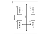
- the processing unit 20 includes a processing device 21, a storage device 22, an input device 23, and an output device 24 that are connected to each other via a bus BU.
- the processing unit 20 is an example of an information processing device.
- the processing device 21 controls each element constituting the processing unit 20 by executing a program stored in the storage device 22. Thereby, the processing unit 20 realizes functions to be described later.
- the processing device 21 includes a CPU (Central Processing Unit).
- the processing device 21 may include an MPU (Micro Processing Unit) or a DSP (Digital Signal Processor) instead of or in addition to the CPU. Further, the processing device 21 may be configured by an LSI (Large Scale Integration).
- the storage device 22 stores information in a readable / writable manner.
- the storage device 22 includes at least one of a RAM (Random Access Memory), a semiconductor memory, and an organic memory.
- the storage device 22 may include at least one of an HDD (Hard Disk Drive) and an SSD (Solid State Drive).
- the storage device 22 may include a recording medium such as a flexible disk, an optical disk, a magneto-optical disk, or a semiconductor memory, and a reading device that can read information from the recording medium.
- the input device 23 inputs information from outside the blood pressure estimation device 1.
- the input device 23 includes a key type button.
- the input device 23 may include a microphone.
- the output device 24 outputs information to the outside of the blood pressure estimation device 1.
- the output device 24 includes a display.
- the output device 24 may include a speaker.
- the processing unit 20 may include a touch panel display that forms both the input device 23 and the output device 24.
- the processing unit 20 estimates the pressure (in other words, blood pressure) of blood flowing through the circulatory system of the living body.
- the mathematical model will be described.
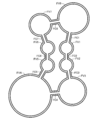
- the mathematical model represents blood flowing through a circulatory system of a living body by a fluid flowing through a flow path in which a plurality of containers that are elastically deformed are connected in an annular shape.
- the flow path in the mathematical model is formed by the first to eighth containers FV1 to FV8 and the first to eighth communication pipes FC1 to FC8.
- the flow path may be formed by nine or more containers.
- the flow path may be formed by nine or more containers and the same number of communication pipes as the containers.
- the first to eighth containers FV1 to FV8 are connected in a ring shape.
- the first to seventh containers FV1 to FV7 and the second to eighth containers FV2 to FV8 are connected by the second to eighth communication pipes FC2 to FC8, respectively.
- the eighth container FV8 and the first container FV1 are connected by the first communication pipe FC1.
- the fluid flows from the first to seventh containers FV1 to FV7 to the second to eighth containers FV2 to FV8, respectively. Further, in the flow path, the fluid flows from the eighth container FV8 to the first container FV1.
- the first to eighth containers FV1 to FV8 include the left atrium, the left ventricle, the artery downstream of the aorta and the aorta, the vena cava and the vein upstream of the vena cava, the right atrium, the right ventricle, Each represents a pulmonary artery and a pulmonary vein.
- Each of the containers FV1 to FV8 is a spherical shell that is elastically deformed.
- the first to eighth differential dP i / dt with respect to time t of the pressure P i of the fluid in the container FVi of the i is represented by Equation 1.
- i represents each integer of 1 to 8.
- Q i represents the flow rate flowing into the i-th container FVi.
- Q i + 1 represents the flow rate flowing out from the i-th container FVi.
- V i is (in other words, no-load volume) pressure P i of the fluid in the container FVi i th volume of the container FVi of the i in the case of 0 represents a.
- E i represents a predetermined coefficient associated with the i th container FVi.
- the coefficient E i may be regarded as a parameter representing a ratio of a change in the pressure P i of the fluid in the i-th container FVi with respect to a change in the volume of the i-th container FVi with respect to time.
- the coefficient E i represents the amount of fluid flowing out from the i-th container FVi per unit time and the change of the no-load volume Vi of the i- th container FVi with respect to time, in the i-th container FVi. It may be regarded as a parameter that represents a ratio of a change in the pressure P i of the fluid in the i-th container FVi with respect to an amount subtracted from the amount of fluid flowing in.
- Unloaded volumes V 1 , V 3 to V 5 , VV of the containers FV1, FV3 to FV5, FV7, and FV8 other than the second and sixth containers FV2 and FV6 among the first to eighth containers FV1 to FV8. 7, V 8 does not change with respect to time.
- the unloaded volumes V 2 and V 6 of the second and sixth containers FV2 and FV6 change with time as expressed in Equation 2. Changes over time of the unloaded volumes V 2 , V 6 of the second and sixth containers FV2, FV6 may be taken to represent pulsations of the left and right ventricles.
- A represents the pulse amplitude detected by the detector 10.
- b represents the pulse rate detected by the detection unit 10.
- ⁇ represents the time (in other words, the time within the cycle) from the time when the cycle starts in one pulse cycle.
- no-load volume f i represents the no-load volume V i .
- No-load volume f i has, pulse amplitudes a, pulse rate b, and the predetermined value in accordance with the time tau.
- no-load volume f i is expressed by Equation 3.
- the unloaded volumes f 2 and f 6 of the second and sixth containers FV2 and FV6 are determined based on the pulse amplitude a and the pulse rate b.
- f i, 0 represents (in other words, reference unloaded volume) pulse amplitude a reference value of the no-load volume f i when the reference value a 0 a.
- the reference unloaded volume f i, 0 is a ratio (in other words, a pulse rate ratio) of time ⁇ from a time point when the cycle starts to a reference value b 0 of the pulse rate b in a single pulse cycle (in other words, a pulse rate ratio) b /. b 0 and a predetermined value.
- the reference unloaded volumes f 2,0 , f 6,0 for the second and sixth containers FV2, FV6 are represented by the curves VL, VR of FIG.
- the flow rate Q 9 exiting from the container FV8 eighth is equal to the flow rate Q 1 that flows into the first container FV1. Further, the flow rates Q i flowing into the first to eighth containers FV1 to FV8 may be regarded as the flow rates in the first to eighth communication pipes FC1 to FC8, respectively.
- Equation 5 The flow rate Q i in each of the communication pipes FC1 to FC8 is expressed by Equation 5.
- the function C is obtained when the pressure P i ⁇ 1 of the upstream container connected to the i th communication pipe FCi is equal to the pressure of the downstream container connected to the i th communication pipe FCi. If less than the pressure P i, it represents 0. Further, as expressed by Expression 6, the function C is obtained when the pressure P i-1 of the upstream container connected to the i- th communication pipe FCi is reduced to the downstream side connected to the i-th communication pipe FCi. When the pressure is not less than the pressure P i of the container, 1 is represented.
- the function C may be taken to represent a valve that prevents the fluid from flowing back (in other words, a check valve).
- the pressure P 0 of the upstream container connected to the first communication pipe FC1 is equal to the pressure P 8 of the downstream container connected to the eighth communication pipe FC8.
- R i represents the resistance to fluid flow from the upstream container connected to the i th communication pipe FCi to the downstream container connected to the i th communication pipe FCi.
- the resistance R i is regarded as a ratio of the difference between the pressures of the fluid in the pair of containers to the flow rate of the fluid between the pair of containers connected to each other among the plurality of containers FV1 to FV8. It's okay.
- g i represents a target value of the resistance R i (in other words, target resistance).
- the resistance R i may be grasped as approaching the target resistance g i with a delay.
- Target resistance g i have, pulse amplitude a, and the predetermined value in accordance with the pulse rate b.
- the target resistance g i is expressed by Equation 9.
- g i, 0 represents (in other words, the reference target resistance) pulse amplitude a reference value of the target resistance g i when the reference value a 0 a.
- Reference target resistance g i, 0 has a value predetermined according to the pulse rate ratio b / b 0.
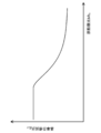
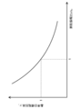
- the reference target resistance g i, 0, as represented in FIG. 5, decreases as the pulse rate ratio b / b 0 increases.
- gamma i represents (in other words, the reference target resistance ratio) the target resistance g i ratio reference target resistance g i, 0 of the.
- the reference target resistance ratio ⁇ i has a predetermined value according to the ratio of the pulse amplitude a to the reference value a 0 (in other words, the pulse amplitude ratio) a / a 0 .
- the reference target resistance ratio gamma i this example, as represented in FIG. 6, with decreases as the pulse amplitude ratio a / a 0 becomes large and the pulse amplitude ratio a / a 0 is 1 1 It is.
- T i represents the time constant of the change of the resistance R i .
- the time constant T i is the change in resistance R i may be seen as indicative of the degree of delay with respect to the change in target resistance g i.
- resistors R 4, R 8 for the fourth and eighth communicating pipe FC4, FC8 of the pulse amplitude a and is determined based on the pulse rate b.
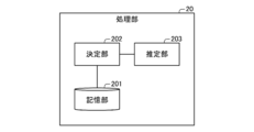
- the function of the processing unit 20 includes a storage unit 201, a determination unit 202, and an estimation unit 203.
- the processing unit 20 calculates the pressures P 1 (t) to P 8 (t) of the fluid in the first to eighth containers FV1 to FV8 at time (in other words, time point t) based on Expressions 1 to 9. From the time t, a process for estimating the pressures P 1 (t + ⁇ t) to P 8 (t + ⁇ t) of the fluid in the first to eighth containers FV1 to FV8 at a time t + ⁇ t after a predetermined step time ⁇ t has elapsed. Run repeatedly.
- the storage unit 201 stores a reference no-load volume f i, 0 and a reference target resistance g i, 0 in advance.
- the processing unit 20, instead of storing the reference no-load volume f i, 0, reference no-load volume f i, 0 may store function calculated.
- the processing unit 20, instead of storing the reference target resistance g i, 0, may store a function for calculating a reference target resistance g i, 0.
- the storage unit 201 stores a reference target resistance ratio ⁇ i in advance.
- the processing unit 20, instead of storing the reference target resistance ratio gamma i may store a function for calculating a reference target resistance ratio gamma i.
- the estimation unit 203 sets the time t, the pressures P 1 to P 8 , and the resistances R 1 to R 8 to an initial value t ini , an initial value P 1, ini to P 8, in i, and an initial value R 1, ini. To R8 , ini , respectively.
- the estimation unit 203 acquires the pulse rate b (t) and the pulse amplitude a (t) at time t based on the pulse rate and pulse amplitude detected by the detection unit 10.
- the estimation unit 203 performs interpolation (for example, based on the time when the pulse rate and pulse amplitude are detected by the detection unit 10, the time t, and the pulse rate and pulse amplitude detected by the detection unit 10. , Linear interpolation), the pulse rate b (t) and the pulse amplitude a (t) at time t are obtained.
- the estimation unit 203 calculates the pulse rate and the pulse amplitude detected by the detection unit 10 at the time closest to the time t without performing interpolation, and calculates the pulse rate b (t) and the pulse amplitude a (t at the time t. ).
- the determination unit 202 is based on the reference target resistance gi , 0 stored in the storage unit 201, Formula 9, and the pulse rate b (t) and the pulse amplitude a (t) acquired by the estimation unit 203. Te, to calculate a target resistance g i.
- the determination unit 202 uses the reference target resistance g i, 0 stored in the storage unit 201, the reference target resistance ratio ⁇ i stored in the storage unit 201, Formula 9, and the estimation unit 203. and obtained pulse rate b (t) and pulse amplitude a (t), on the basis, to calculate a target resistance g i.
- Calculating the target resistances g i is an example of determining a target resistance g i.
- the estimation unit 203 calculates the cycle length ⁇ e at time t based on the acquired pulse rate b (t) and Equation 10.
- Estimating unit 203 sets the periodic start time t 0 to time t.
- Period start time t 0 is the time at which the period of the pulse for each pulse begins.
- the estimation unit 203 calculates the in-period time ⁇ by subtracting the period start time t 0 from the time t.
- the equation 11 is a differential equation for Equation 8, the target resistance g i calculated by the determination unit 202, based on, at time t + Delta] t after a lapse of step time Delta] t from the time t, 4 And resistances R 4 (t + ⁇ t) and R 8 (t + ⁇ t) for the eighth communication pipes FC4 and FC8 are calculated.
- Calculation of the resistance R i is an example of a determination of the resistance R i.
- the determination unit 202 includes the reference no-load volume fi , 0 stored in the storage unit 201, Equation 3, Equation 12, and the pulse rate b (t) and the pulse amplitude a (t acquired by the estimation unit 203. ) And the in-period time ⁇ (t) calculated by the estimation unit 203, the time differentiation ⁇ of the unloaded volumes V 2 and V 6 of the second and sixth containers FV2 and FV6 at the time t. 2 ( ⁇ ) and ⁇ 6 ( ⁇ ) are calculated.
- Time differential [Phi i unloaded volume V i is an example of a change with time of the no-load volume V i.
- Calculating the time derivative [Phi i is an example of a determination of the time derivative [Phi i.
- the storage unit 201 may store a time derivative of the reference no-load volume fi , 0 instead of the reference no-load volume fi , 0 or in addition to the reference no-load volume fi , 0. Good.
- the determination unit 202 calculates the time differential of the reference unloaded volume fi , 0 stored in the storage unit 201, the pulse rate b (t) and the pulse amplitude a (t) acquired by the estimation unit 203. Based on the in-period time ⁇ (t) calculated by the estimation unit 203, the time differentials ⁇ 2 ( 2) of the unloaded volumes V 2 and V 6 of the second and sixth containers FV2 and FV6 at time t. ⁇ ), ⁇ 6 ( ⁇ ) may be calculated.
- the processing unit 20 instead of the storage of the time derivative of the reference no-load volume f i, 0, may store a function for calculating a time derivative of the reference no-load volume f i, 0.
- the unloaded volume V of the containers FV1, FV3 to FV5, FV7, and FV8 other than the second and sixth containers FV2 and FV6 among the first to eighth containers FV1 to FV8. 1 , V 3 to V 5 , V 7 and V 8 do not change with time. Accordingly, the unloaded volumes V 1 , V 3 to V 5 of the containers FV1, FV3 to FV5, FV7, and FV8 other than the second and sixth containers FV2 and FV6 among the first to eighth containers FV1 to FV8. , V 7 , V 8 time derivatives ⁇ 1 ( ⁇ ), ⁇ 3 ( ⁇ ) to ⁇ 5 ( ⁇ ), ⁇ 7 ( ⁇ ), ⁇ 8 ( ⁇ ) are zero.
- the estimation unit 203 is obtained by applying a fourth-order Runge-Kutta method to the differential equation represented by Equation 1, and after the step time ⁇ t has elapsed from time t, based on Equation 13 to Equation 21.
- the pressures P 1 (t + ⁇ t) to P 8 (t + ⁇ t) of the fluid in the first to eighth containers FV1 to FV8 at time t + ⁇ t are calculated.
- Calculation of the pressure P 1 (t + ⁇ t) ⁇ P 8 (t + ⁇ t) are an example of estimation of the pressure P 1 (t + ⁇ t) ⁇ P 8 (t + ⁇ t).
- the estimation unit 203 After estimating the pressures P 1 (t + ⁇ t) to P 8 (t + ⁇ t), the estimation unit 203 updates the time t to the time t + ⁇ t after the step time ⁇ t has elapsed from the time t.
- the estimation unit 203 includes a period ⁇ , resistances R 4 (t + ⁇ t), R 8 (t + ⁇ t), unloaded volumes V 2 , V 6 time derivatives ⁇ 2 ( ⁇ ), ⁇ 6 ( ⁇ ), and pressure P
- the intra-period processing including the calculation of 1 (t + ⁇ t) to P 8 (t + ⁇ t) and the update of the time t is repeatedly executed while the intra-period time ⁇ is equal to or shorter than the period length ⁇ e .
- Estimation unit 203 if the period within the time tau is greater than the period length tau e, acquisition of pulse rate b (t) and pulse amplitude a (t), calculating the target resistances g i and cycle length tau e, and Then, the cycle start time t 0 is set again, and then the intra-cycle processing is performed again.
- the processing unit 20 stores the time t and the pressures P 1 (t) to P 8 (t) at the time t in association with each other.
- the processing unit 20 outputs (for example, displays on the display) the latest blood pressure calculated via the output device 24 every time a predetermined display cycle (for example, 5 seconds) elapses.
- the processing unit 20 outputs the pressure P 3 of the fluid in the third container FV3 as blood pressure.
- the estimation unit 203 calculates the unloaded volume of the second and sixth containers FV2 and FV6 in the period between the in-cycle time ⁇ and the time ⁇ + ⁇ t after the step time ⁇ t has elapsed from the in-cycle time ⁇ .
- a constant value for example, time derivative ⁇ i ( ⁇ ) at the time ⁇ in the cycle
- V 2 and V 6 may be used as the time derivative of V 2 and V 6 .
- the estimation unit 203 may use Formulas 22 to 25 instead of Formula 15, Formula 17, Formula 19, and Formula 21, respectively.
- the estimator 203 determines the resistance to the fourth and eighth communication pipes FC4 and FC8 at time t + ⁇ t / 2 after the lapse of half ⁇ t / 2 of the step time ⁇ t from time t, based on Expression 26.
- R 4 (t + ⁇ t / 2) and R 8 (t + ⁇ t / 2) may be calculated.
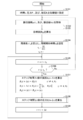
- the detection unit 10 detects the pulse rate and the pulse amplitude every time a predetermined detection period (for example, 1 second) elapses. Further, the processing unit 20 executes the processing shown in FIG. Hereinafter, the processing of FIG. 8 will be described.
- the processing unit 20 sets the time t, the pressures P 1 to P 8 , and the resistances R 1 to R 8 to the initial value t ini , the initial values P 1, ini to P 8, ini , and the initial value R 1, ini. To R8 and ini , respectively (step S101 in FIG. 8).
- the processing unit 20 acquires the pulse rate b (t) and the pulse amplitude a (t) at time t based on the pulse rate and pulse amplitude detected by the detection unit 10 (step S102 in FIG. 8).
- the process part 20 is based on the reference target resistance gi , 0 memorize
- the processing unit 20 includes the reference target resistance g i, 0 stored in the storage unit 201, the reference target resistance ratio ⁇ i stored in the storage unit 201, and the pulse acquired in step S102. the number b (t) and pulse amplitude a (t), on the basis, to calculate a target resistance g i.
- the processing unit 20 calculates the cycle length ⁇ e at time t based on the pulse rate b (t) acquired in step S102, and sets the cycle start time t 0 to time t (FIG. 8). Step S104).
- step S105 the processing unit 20 from the time t, the value obtained by subtracting the periodic start time t 0 which is set in step S104, is calculated as the period in time tau (step S105 in FIG. 8).
- the processing unit 20 determines whether or not the in-period time ⁇ calculated in step S105 is equal to or shorter than the period length ⁇ e calculated in step S104 (step S106 in FIG. 8).
- the processing unit 20 determines “Yes” and proceeds to step S107 in FIG. Then, the processing unit 20 is one other than the fourth and eighth communication pipes FC4 and FC8 among the first to eighth communication pipes FC1 to FC8 at the time t + ⁇ t after the lapse of the step time ⁇ t from the time t. Resistances R 1 (t + ⁇ t) to R 3 (t + ⁇ t) and R 5 (t + ⁇ t) to R 7 (t + ⁇ t) for the communication pipes FC1 to FC3, FC5 to FC7 are changed to resistances R 1 (t) to R 3 (t ), R 5 (t) to R 7 (t), respectively.
- the processing unit 20 sets the resistances R 4 (t + ⁇ t) and R 8 (t + ⁇ t) to the fourth and eighth communication pipes FC4 and FC8 at time t + ⁇ t after the lapse of step time ⁇ t from time t, at step S103. Is calculated based on the target resistance g i calculated in (1).
- the processing unit 20 calculates the pressures P 1 (t + ⁇ t) to P 8 (t + ⁇ t) of the fluid in the first to eighth containers FV1 to FV8 at the time t + ⁇ t after the step time ⁇ t has elapsed from the time t. (Step S108 in FIG. 8). The process of step S108 will be described later.
- the processing unit 20 updates the time t to a time t + ⁇ t after the step time ⁇ t has elapsed from the time t (step S109 in FIG. 8). Then, the processing unit 20 returns to step S105 of FIG. 8, the period in time tau until greater than the period length tau e, it repeats the process from step S105 to step S109.
- processor 20 determines "No" at step S106 in FIG. 8, the flow returns to step S102 in FIG. 8. And the process part 20 performs the process after step S102 again with respect to the time t updated in step S109.
- the processing unit 20 proceeds to step S102 in FIG. 8, the latest time among the times when the pulse rate and the pulse amplitude are detected by the detection unit 10 is updated at time t109. Wait until a future (future) time.
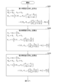
- the processing unit 20 executes the processes shown in FIGS. 9 and 10 as the process of step S108 in FIG. Hereinafter, the processing of FIGS. 9 and 10 will be described.
- the processing unit 20 uses the first provisional pressures P 1,0 to P 8,0 , which are provisional values of the pressures of the fluid in the first to eighth containers FV1 to FV8, at the time t.
- the pressures P 1 (t) to P 8 (t) of the fluid in the containers FV1 to FV8 are set.
- the processing unit 20 sets the first provisional pressures P 0,0 , P 9,0 to be used as the first provisional pressures P 8,0 , P 1,0 for convenience.
- the processing unit 20 includes the first provisional pressures P 0,0 to P 9,0 , the resistances R 1 (t + ⁇ t) to R 9 (t + ⁇ t) calculated in step S107 in FIG. Based on the time derivatives ⁇ 1 ( ⁇ ) to ⁇ 8 ( ⁇ ) at ⁇ , the first time change rates K 1,1 to K 8,1 are calculated (step S201 in FIG. 9).
- the processing unit 20 applies the second provisional pressures P 1,1 to P 8,1 , which are provisional values of the pressures of the fluid in the first to eighth containers FV1 to FV8, at the time t. 8 to the fluid pressures P 1 (t) to P 8 (t) in the containers FV1 to FV8, the first time rate of change K 1,1 to K 8,1 calculated in step S201 of FIG. A value obtained by adding a product of a value obtained by dividing the step time ⁇ t by 2 is set.
- the processing unit 20 sets the second provisional pressures P 0,1 , P 9,1 to be used as the second provisional pressures P 8,1 , P 1,1 for convenience.
- the processing unit 20 includes the second provisional pressures P 0,1 to P 9,1 , the resistances R 1 (t + ⁇ t) to R 9 (t + ⁇ t) calculated in step S107 in FIG.
- the second time change rate K 1,2 to K 8,2 is calculated (step S202 in FIG. 9).
- a third interim pressure P 1,2 ⁇ P 8,2 is a provisional value of the pressure of the fluid in the container FV1 ⁇ FV8 first to eighth, at time t, first to 8 to the fluid pressures P 1 (t) to P 8 (t) in the containers FV1 to FV8, the second time rate of change K 1,2 to K 8,2 calculated in step S202 of FIG.
- a value obtained by adding a product of a value obtained by dividing the step time ⁇ t by 2 is set.
- the processing unit 20 sets the third provisional pressures P 0,2 , P 9,2 used as the third provisional pressures P 8,2 , P 1,2 respectively.
- the processing unit 20 includes the third provisional pressures P 0,2 to P 9,2 , the resistances R 1 (t + ⁇ t) to R 9 (t + ⁇ t) calculated in step S107 in FIG. Based on the time derivatives ⁇ 1 ( ⁇ + ⁇ t / 2) to ⁇ 8 ( ⁇ + ⁇ t / 2) at the time ⁇ + ⁇ t / 2 after half the step time ⁇ t from ⁇ , the third rate of change K 1,3 to K 8,3 is calculated (step S203 in FIG. 9).
- the processing unit 20 applies the fourth provisional pressures P 1,3 to P 8,3 , which are provisional values of the pressures of the fluid in the first to eighth containers FV1 to FV8, at the time t. 8 to the fluid pressures P 1 (t) to P 8 (t) in the containers FV1 to FV8, the third rate of change K 1,3 to K 8,3 calculated in step S203 of FIG. Each is set to a value obtained by adding the product of the step time ⁇ t.
- the processing unit 20 sets the fourth provisional pressures P 0,3 , P 9,3 to be used as the fourth provisional pressures P 8,3 , P 1,3 for convenience .
- the processing unit 20 includes the fourth provisional pressures P 0,3 to P 9,3 , the resistances R 1 (t + ⁇ t) to R 9 (t + ⁇ t) calculated in step S107 in FIG. Based on the time differentials ⁇ 1 ( ⁇ + ⁇ t) to ⁇ 8 ( ⁇ + ⁇ t) at time ⁇ + ⁇ t after ⁇ by step time ⁇ t, fourth time change rates K 1,4 to K 8,4 are calculated (FIG. 10). Step S204).
- the processing unit 20 calculates the pressures P 1 (t) to P 8 (t) of the fluid in the first to eighth containers FV1 to FV8 at time t and Steps S201 to S204, respectively.
- Step S205 And the process part 20 complete
- the blood pressure estimation device 1 detects the first parameter (in this example, the pulse rate b) representing the cycle length that is the length of the cycle of the heartbeat of the living body. Furthermore, the blood pressure estimation device 1 uses a plurality of containers FV1 to FV8 in a mathematical model that represents blood flowing through a circulatory system of a living body by a fluid flowing through a flow path in which a plurality of containers FV1 to FV8 that are elastically deformed are connected in an annular shape.
- the first parameter in this example, the pulse rate b
- the blood pressure estimation device 1 uses a plurality of containers FV1 to FV8 in a mathematical model that represents blood flowing through a circulatory system of a living body by a fluid flowing through a flow path in which a plurality of containers FV1 to FV8 that are elastically deformed are connected in an annular shape.
- the blood pressure estimation device 1 estimates the pressure of blood flowing through the circulatory system of the living body based on the determined change and the mathematical model.
- the first parameter representing the cycle length is easily detected with higher accuracy than the artery diameter. Furthermore, by using the change with respect to time of the unloaded volumes V 2 and V 6 of the second and sixth containers FV2 and FV6 determined based on the first parameter, the mathematical model can be obtained from the left ventricle and the living body in the living body. The behavior of the right ventricle can be expressed with high accuracy. As a result, the mathematical model can express the behavior of blood flowing through the living body's circulatory system with high accuracy. Thus, the blood pressure estimation apparatus 1 can estimate the pressure P i which the blood has with high accuracy.
- the blood pressure estimation device 1 has a pressure between containers of the pressure of the fluid in the pair of containers with respect to the flow rate of the fluid between the pair of containers connected to each other among the plurality of containers FV1 to FV8.
- the resistor R 4 for the fourth and eighth communicating pipe FC4, FC8 of, R 8) resistance is the ratio of the difference to be determined based on the first parameter detected.
- the blood pressure estimation device 1 estimates the pressure of blood flowing through the circulatory system of the living body based on the determined resistance.
- the mathematical model can represent the behavior of the peripheral blood vessels in the living body with higher accuracy than when the resistances R 4 and R 8 are kept constant. Thereby, the mathematical model can express the behavior of blood flowing through the circulatory system of a living body with high accuracy. As a result, the blood pressure estimation apparatus 1 can estimate the pressure P i with blood at high accuracy.
- the blood pressure estimation apparatus 1 of the first embodiment the resistance (in this example, resistors R 4, R 8 for the fourth and eighth communicating pipe FC4, FC8) of the target value (in this example, the target resistance g 4 , G 8 ) are determined based on the detected first parameter.
- the blood pressure estimation device 1 determines the resistance so that the resistance approaches the determined target value with a delay.
- the mathematical model can represent the behavior of the peripheral blood vessels in the living body with higher accuracy.
- the mathematical model can express the behavior of blood flowing through the circulatory system of a living body with high accuracy.
- the blood pressure estimation apparatus 1 the pressure P i with the blood flowing through the circulatory system of a living body can be estimated with high accuracy.
- the blood pressure estimation device 1 of the first embodiment detects a second parameter (pulse amplitude a in this example) that represents the magnitude of the heartbeat.
- a second parameter pulse amplitude a in this example
- the blood pressure estimation apparatus 1 based on the second parameter detected, the resistance (in this example, resistors R 4, R 8 for the fourth and eighth communicating pipe FC4, FC8) of the target value of the (in this example Then, the target resistances g 4 and g 8 ) are determined.
- the mathematical model can represent the behavior of the peripheral blood vessels in the living body with higher accuracy.
- the mathematical model can express the behavior of blood flowing through the circulatory system of a living body with high accuracy.
- the blood pressure estimation apparatus 1 the pressure P i with the blood flowing through the circulatory system of a living body can be estimated with high accuracy.
- the blood pressure estimation device 1 of the first embodiment changes the unloaded volume with respect to time of at least one of the plurality of containers FV1 to FV8 based on the detected second parameter (in this example, the first parameter 2 and the time differentials ⁇ 2 and ⁇ 6 of the unloaded volumes V 2 and V 6 of the sixth containers FV2 and FV6).
- the mathematical model can represent the behavior of the left ventricle and the right ventricle in the living body with higher accuracy.
- the mathematical model can express the behavior of blood flowing through the circulatory system of a living body with high accuracy.
- the blood pressure estimation apparatus 1 the pressure P i with the blood flowing through the circulatory system of a living body can be estimated with high accuracy.
- the plurality of containers FV1 to FV8 include the left atrium, the left ventricle, the aorta and the artery downstream of the aorta, the vena cava and the vein upstream of the vena cava, the right Represents the atrium, right ventricle, pulmonary artery, and pulmonary vein, respectively.
- the mathematical model can express the behavior of blood flowing through the circulatory system of a living body with high accuracy.
- the blood pressure estimation apparatus 1 the pressure P i with the blood flowing through the circulatory system of a living body can be estimated with high accuracy.
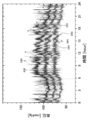
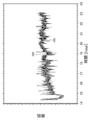
- a curve D11 in FIG. 11 represents an example of the pulse rate detected by the blood pressure estimation device 1 when the living body is at rest.
- 12 to 14 show an example of an estimation result by the blood pressure estimation device 1 when the pulse rate detected by the blood pressure estimation device 1 changes as shown in FIG.
- Circles D12, D13, and D14 in FIG. 12 are the maximum blood pressure (in other words, the highest value of blood pressure), the lowest blood pressure (in other words, the lowest value of blood pressure), and the average blood pressure measured by the blood pressure measurement device as a comparative example. (In other words, the average value of blood pressure).
- the blood pressure measurement device measures blood pressure by using a cuff.
- the average blood pressure is a value obtained by averaging the maximum blood pressure and the minimum blood pressure.
- Curves E12, E13, and E14 in FIG. 12 represent the maximum blood pressure, the minimum blood pressure, and the average blood pressure estimated by the blood pressure estimation device 1, respectively. As shown in FIG. 12, according to the blood pressure estimation device 1 of the first embodiment, blood pressure can be estimated with high accuracy.
- Curve E15, E16 in FIG. 13 represents a fourth target value g 4 of the resistor R 4 for communicating conduit FC4, and the resistance R 4 for the fourth communicating pipe FC4, respectively.
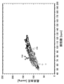
- a square D18 in FIG. 14 represents the maximum blood pressure measured by the blood pressure measurement device as a comparative example.
- a circle E18 in FIG. 14 represents the systolic blood pressure estimated by the blood pressure estimation device 1. As shown in FIG. 14, according to the blood pressure estimation device 1 of the first embodiment, the relationship between the maximum blood pressure and the pulse rate can be estimated with high accuracy.
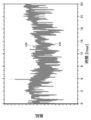
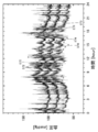
- 15 represents an example of the pulse rate detected by the blood pressure estimation device 1 during the movement of the living body.
- 16 to 18 show an example of an estimation result by the blood pressure estimation device 1 when the pulse rate detected by the blood pressure estimation device 1 changes as shown in FIG.
- circles D22, D23, and D24 represent the systolic blood pressure, the diastolic blood pressure, and the average blood pressure, respectively, measured by a blood pressure measurement device as a comparative example.
- the blood pressure measurement device measures blood pressure by using a cuff.
- FIG. 16 represent the maximum blood pressure, the minimum blood pressure, and the average blood pressure estimated by the blood pressure estimation apparatus 1, respectively. As shown in FIG. 16, according to the blood pressure estimation device 1 of the first embodiment, blood pressure can be estimated with high accuracy.
- Curve E25, E26 in FIG. 17 represents a fourth target value g 4 of the resistor R 4 for communicating conduit FC4, and the resistance R 4 for the fourth communicating pipe FC4, respectively.
- a square D28 in FIG. 18 represents the systolic blood pressure measured by the blood pressure measurement device as a comparative example.
- a circle E28 in FIG. 18 represents the systolic blood pressure estimated by the blood pressure estimation device 1. As shown in FIG. 18, according to the blood pressure estimation device 1 of the first embodiment, the relationship between the maximum blood pressure and the pulse rate can be estimated with high accuracy.
- the blood pressure estimation device 1 may include a first device that constitutes the detection unit 10 and a second device that constitutes the processing unit 20.
- the first device and the second device are communicably connected to each other.
- the second device may be a mobile phone, a smartphone, a personal computer, or a server device.
- the blood pressure estimation device 1 performs the detection of the pulse rate and the estimation of the blood pressure at the time when the pulse rate is detected in parallel. By the way, after the detection of the pulse rate in the predetermined period is completed, the blood pressure estimation apparatus 1 may estimate the blood pressure in the period.
- the blood pressure estimation device 1 stores each of a plurality of different times and the pressure at the time in association with each other.
- the blood pressure estimation device 1 may output each of a plurality of stored times in association with the stored pressure at that time.
- the blood pressure estimation device 1 may output a graph representing changes in pressure with respect to time.
- the processing unit 20 sets the resistances R 4 and R 8 for the fourth and eighth communication pipes FC 4 and FC 8 to initial values R 4, ini , R 8, and ini , respectively, and changes them with time. Instead, the blood pressure may be estimated.
- the blood pressure estimation device 1 receives information representing a pulse rate and blood pressure measured in advance with respect to the living body, and based on the input information, the reference target resistance g i, 0 , the initial value of the resistance At least one of R i, ini and coefficient E i may be determined.
- a blood pressure estimation device according to a first modification of the first embodiment will be described.
- the blood pressure estimation device according to the first modification of the first embodiment is different from the blood pressure estimation device according to the first embodiment in that a second parameter representing the magnitude of a heartbeat of a living body is estimated based on the first parameter. is doing.
- the difference will be mainly described.
- 1st modification of 1st Embodiment what attached
- the processing unit 20 estimates the pulse amplitude a based on the pulse rate b detected by the detection unit 10 and the mathematical expression 27. Further, the processing unit 20 determines the unloaded volumes f 2 and f 6 of the second and sixth containers FV2 and FV6 based on the estimated pulse amplitude a, and the fourth and eighth communication pipes FC4. , to calculate the target resistance g 4, g 8 for FC8.
- T a represents the time constant of the change of the pulse amplitude a.
- the time constant Ta may be understood as representing the degree to which the change in the pulse amplitude a is delayed with respect to the change in the target amplitude h.
- the pulse amplitude a may be grasped as approaching the target amplitude h with a delay.
- the target amplitude h has a value determined in advance according to the pulse rate ratio b / b 0 . In this example, the target amplitude h increases as the pulse rate ratio b / b 0 increases, as represented by FIG.
- the blood pressure estimation device 1 may determine the target amplitude h based on the information indicating the pulse rate and blood pressure measured in advance with respect to the living body and the input information.
- the estimation unit 203 acquires the pulse rate b (t) at the time t based on the pulse rate detected by the detection unit 10. Furthermore, the estimation unit 203 calculates the pulse amplitude a at time t + ⁇ t after the step time ⁇ t has elapsed from time t, based on Equation 28, which is a difference equation with respect to Equation 27, and the acquired pulse rate b (t). (T + ⁇ t) is calculated.
- the calculation of the pulse amplitude a is an example of the estimation of the pulse amplitude a.
- the detection unit 10 does not have to detect the second parameter indicating the magnitude of the heartbeat of the living body.
- the same operations and effects as the blood pressure estimation device 1 of the first embodiment are exhibited.
- 20 to 22 show an example of an estimation result obtained by the blood pressure estimation device 1 when the pulse rate detected by the blood pressure estimation device 1 changes as shown in FIG.
- circles D32, D33, and D34 respectively represent the systolic blood pressure, the diastolic blood pressure, and the average blood pressure measured by the blood pressure measuring device as a comparative example.
- the blood pressure measurement device measures blood pressure by using a cuff.
- curves E32, E33, and E34 represent the maximum blood pressure, the minimum blood pressure, and the average blood pressure estimated by the blood pressure estimation device 1, respectively.
- blood pressure can be estimated with high accuracy.
- Curve E35, E36 in FIG. 21 represents a fourth target value g 4 of the resistor R 4 for communicating conduit FC4, and the resistance R 4 for the fourth communicating pipe FC4, respectively.
- a square D38 in FIG. 22 represents the systolic blood pressure measured by the blood pressure measurement device as a comparative example.
- a circle E38 in FIG. 22 represents the systolic blood pressure estimated by the blood pressure estimation device 1. As shown in FIG. 22, according to the blood pressure estimation device 1 of the first modification of the first embodiment, the relationship between the maximum blood pressure and the pulse rate can be estimated with high accuracy.
- 23 to 25 show examples of estimation results by the blood pressure estimation device 1 when the pulse rate detected by the blood pressure estimation device 1 changes as shown in FIG.
- circles D42, D43, and D44 respectively represent the systolic blood pressure, the diastolic blood pressure, and the average blood pressure measured by the blood pressure measurement device as a comparative example.
- the blood pressure measurement device measures blood pressure by using a cuff.
- curves E42, E43, and E44 represent the maximum blood pressure, the minimum blood pressure, and the average blood pressure estimated by the blood pressure estimation device 1, respectively. As shown in FIG. 23, according to the blood pressure estimation device 1 of the first modification of the first embodiment, blood pressure can be estimated with high accuracy.
- Curve E45, E46 in FIG. 24 represents a fourth target value g 4 of the resistor R 4 for communicating conduit FC4, and the resistance R 4 for the fourth communicating pipe FC4, respectively.
- a square D48 in FIG. 25 represents the systolic blood pressure measured by the blood pressure measurement device as a comparative example.
- a circle E48 in FIG. 25 represents the systolic blood pressure estimated by the blood pressure estimation device 1. As shown in FIG. 25, according to the blood pressure estimation device 1 of the first modified example of the first embodiment, the relationship between the maximum blood pressure and the pulse rate can be estimated with high accuracy.
- the blood pressure estimation apparatus uses a predetermined function to compare the blood pressure estimation apparatus according to the first modification of the first embodiment with a reference target resistance g i, 0 and a reference target resistance.
- the difference is that the ratio ⁇ i , the resistance R 4,0 to the fourth communication pipe FC4 when the living body is at rest, and the coefficient E 4 associated with the fourth container FV4 are calculated.
- the difference will be mainly described.
- symbol used in the 1st modification of 1st Embodiment is the same or substantially the same.
- Processing unit 20 instead of the storage of the reference target resistance ratio gamma i, and stores a function for calculating a reference target resistance ratio gamma i.
- the processing unit 20 stores a function represented by Expression 29 as a function for calculating the reference target resistance ratio ⁇ i .
- the processing unit 20 calculates the reference target resistance ratio ⁇ i based on Expression 29.
- the processing unit 20 instead of storing the reference target resistance g i, 0, and stores the function for calculating the reference target resistance g i, 0.
- the processing unit 20 stores a function represented by Expression 30 as a function for calculating the reference target resistance gi , 0 .
- the processing unit 20 calculates the reference target resistance g i, 0 based on Equation 30.
- R i, 0 represents the resistance to the i th communication pipe FCi when the living body is at rest.
- the processing unit 20 sets the resistance R 4,0 to the fourth communication pipe FC4 when the living body is resting, the reference value b 0 of the pulse rate b, and the maximum blood pressure P smax measured when the living body is resting. And based on the minimum blood pressure P smin measured when the living body is resting, the predetermined coefficient ⁇ , and Equation 31.
- the reference value b 0 of the pulse rate b is a pulse rate measured when the living body is at rest.
- the coefficient ⁇ may be changed every time blood pressure estimation is executed.
- the coefficient ⁇ may be set to a value according to the living body.
- the processing unit 20 uses the coefficient E 4 associated with the fourth container FV4 as the maximum blood pressure P smax measured when the living body is resting and the minimum blood pressure P smin measured when the living body is resting. , Based on a predetermined coefficient ⁇ and Expression 32.
- the coefficient ⁇ may be changed every time blood pressure estimation is executed. Also, the coefficient ⁇ may be set to a value according to the living body.
- the processing unit 20 uses a fixed value (in other words, a value common to a plurality of different living bodies) as the resistance R 8,0 for the eighth communication pipe FC8.
- the resistance R 8,0 to the eighth communication pipe FC8 may be changed every time blood pressure estimation is executed. Further, the resistance R 8,0 for the eighth communication pipe FC8 may be set to a value corresponding to the living body.
- the processing unit 20 uses a fixed value as the coefficient E j associated with the jth container FVj.
- j represents each integer other than 4 among 1 to 8 integers.
- the coefficient E j associated with the jth container FVj may be changed every time blood pressure estimation is executed.
- the coefficient E j associated with the jth container FVj may be set to a value corresponding to the living body.
- the same operations and effects as the blood pressure estimation device 1 of the first modification of the first embodiment are exhibited.
- 26 to 29 show an example of an estimation result by the blood pressure estimation device 1 when the pulse rate detected by the blood pressure estimation device 1 changes as shown in FIG.
- circles D92, D93, and D94 represent the systolic blood pressure, the diastolic blood pressure, and the average blood pressure, respectively, measured by a blood pressure measurement device as a comparative example.
- the blood pressure measurement device measures blood pressure by using a cuff.
- curves E92, E93, and E94 represent the maximum blood pressure, the minimum blood pressure, and the average blood pressure estimated by the blood pressure estimation device 1, respectively.
- blood pressure can be estimated with high accuracy.
- Curve E95, E96 in FIG. 27 represents a fourth target value g 4 of the resistor R 4 for communicating conduit FC4, and the resistance R 4 for the fourth communicating pipe FC4, respectively.
- a square D98 in FIG. 28 represents the maximum blood pressure measured by the blood pressure measurement device as a comparative example.
- a circle E98 in FIG. 28 represents the systolic blood pressure estimated by the blood pressure estimation device 1. As shown in FIG. 28, according to the blood pressure estimation device 1 of the second modification of the first embodiment, the relationship between the maximum blood pressure and the pulse rate can be estimated with high accuracy.
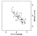
- the blood pressure measured by the blood pressure measuring device is represented as measured blood pressure
- the blood pressure estimated by the blood pressure estimating device 1 is represented as estimated blood pressure.
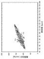
- a square F91 in FIG. 29 represents the relationship between the maximum blood pressure measured by the blood pressure measurement device as a comparative example and the maximum blood pressure estimated by the blood pressure estimation device 1.
- a triangle F92 in FIG. 29 represents the relationship between the minimum blood pressure measured by the blood pressure measurement device as a comparative example and the minimum blood pressure estimated by the blood pressure estimation device 1.
- a circle F93 in FIG. 29 represents the relationship between the average blood pressure measured by the blood pressure measurement device as a comparative example and the average blood pressure estimated by the blood pressure estimation device 1.
- the maximum blood pressure, the minimum blood pressure, and the average blood pressure can be estimated with high accuracy.
- a blood pressure estimation device according to a third modification of the first embodiment will be described.
- the blood pressure estimation device according to the third modification of the first embodiment is different from the blood pressure estimation device according to the first embodiment in that the blood pressure is estimated without being based on the second parameter representing the magnitude of the heartbeat of the living body. ing.
- the difference will be mainly described.
- the 3rd modification of 1st Embodiment what attached
- the target value g 4, g 8 of resistors R 4, R 8 for the fourth and eighth communicating pipe FC4, FC8 of is represented by equation 34 in place of Equation 9.
- the detection unit 10 does not have to detect the second parameter indicating the magnitude of the heartbeat of the living body.
- the same operations and effects as the blood pressure estimation device 1 of the first embodiment are exhibited.
- 30 to 32 show an example of an estimation result by the blood pressure estimation device 1 when the pulse rate detected by the blood pressure estimation device 1 changes as shown in FIG.
- circles D52, D53, and D54 represent the systolic blood pressure, the diastolic blood pressure, and the average blood pressure, respectively, measured by a blood pressure measurement device as a comparative example.
- the blood pressure measurement device measures blood pressure by using a cuff.
- curves E52, E53, and E54 represent the maximum blood pressure, the minimum blood pressure, and the average blood pressure estimated by the blood pressure estimation device 1, respectively.
- blood pressure can be estimated with high accuracy.
- Curve E55, E56 in FIG. 31 represents a fourth target value g 4 of the resistor R 4 for communicating conduit FC4, and the resistance R 4 for the fourth communicating pipe FC4, respectively.
- a square D58 in FIG. 32 represents the systolic blood pressure measured by the blood pressure measurement device as a comparative example.
- a circle E58 in FIG. 32 represents the systolic blood pressure estimated by the blood pressure estimation device 1. As shown in FIG. 32, according to the blood pressure estimation device 1 of the third modification of the first embodiment, the relationship between the maximum blood pressure and the pulse rate can be estimated with high accuracy.
- 33 to 35 show an example of an estimation result obtained by the blood pressure estimation device 1 when the pulse rate detected by the blood pressure estimation device 1 changes as shown in FIG.
- circles D62, D63, and D64 represent the systolic blood pressure, the diastolic blood pressure, and the average blood pressure, respectively, measured by a blood pressure measurement device as a comparative example.
- the blood pressure measurement device measures blood pressure by using a cuff.
- curves E62, E63, and E64 represent the maximum blood pressure, the minimum blood pressure, and the average blood pressure estimated by the blood pressure estimation device 1, respectively.
- blood pressure can be estimated with high accuracy.
- Curve E65, E66 in FIG. 34 represents a fourth target value g 4 of the resistor R 4 for communicating conduit FC4, and the resistance R 4 for the fourth communicating pipe FC4, respectively.
- a square D68 in FIG. 35 represents the maximum blood pressure measured by the blood pressure measurement device as a comparative example.
- a circle E68 in FIG. 35 represents the systolic blood pressure estimated by the blood pressure estimation device 1. As shown in FIG. 35, according to the blood pressure estimation device 1 of the third modification of the first embodiment, the relationship between the maximum blood pressure and the pulse rate can be estimated with high accuracy.
- a blood pressure estimation device according to a fourth modification of the first embodiment will be described.
- the blood pressure estimation apparatus according to the fourth modification of the first embodiment is different from the blood pressure estimation apparatus according to the third modification of the first embodiment in that blood pressure is estimated without changing the resistance with respect to time. ing.
- the difference will be mainly described.
- symbol used in 1st Embodiment is the same or substantially the same.
- the processing unit 20 sets the resistances R 4 and R 8 for the fourth and eighth communication pipes FC 4 and FC 8 to the initial values R 4, ini , R 8, and ini , respectively, and does not change them with respect to time. According to the blood pressure estimation device 1 of the fourth modified example of the first embodiment, the same operations and effects as the blood pressure estimation device 1 of the first embodiment are exhibited.
- 36 to 38 show an example of an estimation result by the blood pressure estimation device 1 when the pulse rate detected by the blood pressure estimation device 1 changes as shown in FIG.
- circles D72, D73, and D74 represent the systolic blood pressure, the diastolic blood pressure, and the average blood pressure, respectively, measured by a blood pressure measurement device as a comparative example.
- the blood pressure measurement device measures blood pressure by using a cuff.
- curves E72, E73, and E74 represent the maximum blood pressure, the minimum blood pressure, and the average blood pressure estimated by the blood pressure estimation device 1, respectively.
- blood pressure can be estimated with high accuracy.
- Curve E76 in FIG. 37 represents the resistance R 4 for the fourth communicating pipe FC4.
- a square D78 in FIG. 38 represents the maximum blood pressure measured by the blood pressure measurement device as a comparative example.
- a circle E78 in FIG. 38 represents the systolic blood pressure estimated by the blood pressure estimation device 1.
- the relationship between the maximum blood pressure and the pulse rate can be estimated with high accuracy.
- 39 to 41 show examples of estimation results by the blood pressure estimation device 1 when the pulse rate detected by the blood pressure estimation device 1 changes as shown in FIG.
- circles D82, D83, and D84 represent the systolic blood pressure, the diastolic blood pressure, and the average blood pressure, respectively, measured by a blood pressure measurement device as a comparative example.
- the blood pressure measurement device measures blood pressure by using a cuff.
- curves E82, E83, and E84 represent the maximum blood pressure, the minimum blood pressure, and the average blood pressure estimated by the blood pressure estimation device 1, respectively.
- blood pressure can be estimated with high accuracy.
- Curve E86 in FIG. 40 represents a resistance R 4 for the fourth communicating pipe FC4.
- a square D88 in FIG. 41 represents the systolic blood pressure measured by the blood pressure measurement device as a comparative example.
- a circle E88 in FIG. 41 represents the systolic blood pressure estimated by the blood pressure estimation device 1.
- the relationship between the maximum blood pressure and the pulse rate can be estimated with high accuracy.
Landscapes
- Health & Medical Sciences (AREA)
- Life Sciences & Earth Sciences (AREA)
- Engineering & Computer Science (AREA)
- Public Health (AREA)
- Molecular Biology (AREA)
- Cardiology (AREA)
- Veterinary Medicine (AREA)
- Physics & Mathematics (AREA)
- General Health & Medical Sciences (AREA)
- Biophysics (AREA)
- Pathology (AREA)
- Biomedical Technology (AREA)
- Heart & Thoracic Surgery (AREA)
- Medical Informatics (AREA)
- Physiology (AREA)
- Surgery (AREA)
- Animal Behavior & Ethology (AREA)
- Computer Vision & Pattern Recognition (AREA)
- Artificial Intelligence (AREA)
- Signal Processing (AREA)
- Psychiatry (AREA)
- Vascular Medicine (AREA)
- Measuring Pulse, Heart Rate, Blood Pressure Or Blood Flow (AREA)
- Hematology (AREA)
Abstract
血圧推定装置(1)は、生体の心拍の周期の長さである周期長を表す第1パラメータを検出する検出部(10)と、弾性変形する複数の容器が環状に連結された流路を流れる流体によって、上記生体の循環器系を流れる血液を表す数理モデルにおける、上記複数の容器のうちの少なくとも1つの容器の容積の時間に対する変化を、上記検出された第1パラメータに基づいて決定し、上記決定された変化と、上記数理モデルと、に基づいて、上記血液が有する圧力を推定する処理部(20)と、を備える。
Description
本発明は、血圧推定装置、情報処理装置、血圧推定方法、及び、血圧推定プログラムに関する。
生体の循環器系を流れる血液が有する圧力(換言すると、血圧)を推定する血圧推定装置が知られている(例えば、特許文献1を参照)。血圧推定装置は、指の表面における2つの位置にて動脈径を検出するとともに、当該2つの位置の間の生体の電気インピーダンスを検出する。更に、血圧推定装置は、検出された動脈径及び電気インピーダンスと、カルマンフィルタと、に基づいて血圧を推定する。
ところで、動脈径及び電気インピーダンスは、高い精度にて検出されにくい。このため、上記血圧推定装置において、血圧を高い精度にて推定できないことがあった。
本発明の目的の一つは、血圧を高い精度にて推定することにある。
一つの側面では、血圧推定装置は、
生体の心拍の周期の長さである周期長を表す第1パラメータを検出する検出部と、
弾性変形する複数の容器が環状に連結された流路を流れる流体によって、上記生体の循環器系を流れる血液を表す数理モデルにおける、上記複数の容器のうちの少なくとも1つの容器の容積の時間に対する変化を、上記検出された第1パラメータに基づいて決定し、上記決定された変化と、上記数理モデルと、に基づいて、上記血液が有する圧力を推定する処理部と、
を備える。
生体の心拍の周期の長さである周期長を表す第1パラメータを検出する検出部と、
弾性変形する複数の容器が環状に連結された流路を流れる流体によって、上記生体の循環器系を流れる血液を表す数理モデルにおける、上記複数の容器のうちの少なくとも1つの容器の容積の時間に対する変化を、上記検出された第1パラメータに基づいて決定し、上記決定された変化と、上記数理モデルと、に基づいて、上記血液が有する圧力を推定する処理部と、
を備える。
他の一つの側面では、情報処理装置は、
弾性変形する複数の容器が環状に連結された流路を流れる流体によって、生体の循環器系を流れる血液を表す数理モデルにおける、上記複数の容器のうちの少なくとも1つの容器の容積の時間に対する変化を、検出された、上記生体の心拍の周期の長さである周期長を表す第1パラメータに基づいて決定する決定部と、
上記決定された変化と、上記数理モデルと、に基づいて、上記血液が有する圧力を推定する推定部と、
を備える。
弾性変形する複数の容器が環状に連結された流路を流れる流体によって、生体の循環器系を流れる血液を表す数理モデルにおける、上記複数の容器のうちの少なくとも1つの容器の容積の時間に対する変化を、検出された、上記生体の心拍の周期の長さである周期長を表す第1パラメータに基づいて決定する決定部と、
上記決定された変化と、上記数理モデルと、に基づいて、上記血液が有する圧力を推定する推定部と、
を備える。
他の一つの側面では、血圧推定方法は、
弾性変形する複数の容器が環状に連結された流路を流れる流体によって、生体の循環器系を流れる血液を表す数理モデルにおける、上記複数の容器のうちの少なくとも1つの容器の容積の時間に対する変化を、検出された、上記生体の心拍の周期の長さである周期長を表す第1パラメータに基づいて決定し、
上記決定された変化と、上記数理モデルと、に基づいて、上記血液が有する圧力を推定する。
弾性変形する複数の容器が環状に連結された流路を流れる流体によって、生体の循環器系を流れる血液を表す数理モデルにおける、上記複数の容器のうちの少なくとも1つの容器の容積の時間に対する変化を、検出された、上記生体の心拍の周期の長さである周期長を表す第1パラメータに基づいて決定し、
上記決定された変化と、上記数理モデルと、に基づいて、上記血液が有する圧力を推定する。
他の一つの側面では、血圧推定プログラムは、
弾性変形する複数の容器が環状に連結された流路を流れる流体によって、生体の循環器系を流れる血液を表す数理モデルにおける、上記複数の容器のうちの少なくとも1つの容器の容積の時間に対する変化を、検出された、上記生体の心拍の周期の長さである周期長を表す第1パラメータに基づいて決定し、
上記決定された変化と、上記数理モデルと、に基づいて、上記血液が有する圧力を推定する、処理をコンピュータに実行させる。
弾性変形する複数の容器が環状に連結された流路を流れる流体によって、生体の循環器系を流れる血液を表す数理モデルにおける、上記複数の容器のうちの少なくとも1つの容器の容積の時間に対する変化を、検出された、上記生体の心拍の周期の長さである周期長を表す第1パラメータに基づいて決定し、
上記決定された変化と、上記数理モデルと、に基づいて、上記血液が有する圧力を推定する、処理をコンピュータに実行させる。
血圧を高い精度にて推定できる。
以下、本発明の、血圧推定装置、情報処理装置、血圧推定方法、及び、血圧推定プログラム、に関する各実施形態について図1乃至図41を参照しながら説明する。
<第1実施形態>
(構成)
図1に表されるように、第1実施形態の血圧推定装置1は、検出部10と、処理部20と、を備える。本例では、血圧推定装置1は、腕時計型である。なお、血圧推定装置1は、腕時計型と異なる型(例えば、絆創膏型等)であってもよい。
(構成)
図1に表されるように、第1実施形態の血圧推定装置1は、検出部10と、処理部20と、を備える。本例では、血圧推定装置1は、腕時計型である。なお、血圧推定装置1は、腕時計型と異なる型(例えば、絆創膏型等)であってもよい。
検出部10は、生体の心拍(換言すると、脈拍)の周期の長さである周期長を表す第1パラメータを検出する。本例では、生体は、人間の生体である。なお、生体は、人間以外の動物の生体であってもよい。
本例では、第1パラメータは、脈拍数である。脈拍数は、所定の単位時間(本例では、1分)あたりの生体の脈拍の数である。本例では、脈拍数は、1回の脈拍の周期長により単位時間を除することにより算出される。なお、周期長は、単位時間を脈拍数により除することにより算出されてもよい。なお、第1パラメータは、周期長であってもよい。
更に、検出部10は、生体の心拍の大きさを表す第2パラメータを検出する。本例では、第2パラメータは、動脈における血液の量を表す信号の、1回の脈拍における最小値及び最大値の差である。なお、第2パラメータは、動脈の幅、動脈の断面積、動脈における血液の量、動脈における血液の流量、動脈における血液の流速、又は、これらの少なくとも1つを表す信号の、1回の脈拍における最小値及び最大値の差であってもよい。第2パラメータは、脈拍振幅と表されてもよい。
本例では、検出部10は、生体の動脈に光を照射するとともに、当該光が当該生体によって反射された光の強度を検出し、検出された強度の時間に対する変化に基づいて、脈拍数及び脈拍振幅を検出する。例えば、検出部10は、検出された強度の変化において連続する2つのピーク間の時間に基づいて脈拍数を検出する。また、例えば、検出部10は、検出された強度の変化において連続する2つのピーク間における、強度の最小値及び強度の最大値の差に基づいて脈拍振幅を検出する。
なお、検出部10は、動脈の近傍(例えば、手首等)において生体の表面を押圧する部材を備えるとともに、当該部材が当該表面から受ける圧力を検出することにより、脈拍数及び脈拍振幅を検出してもよい。この場合、検出部10は、圧電素子を用いることにより、圧力の検出を行なってよい。
また、検出部10は、心臓の近傍において生体の表面に取り付けられた電極を備えるとともに、当該電極を介して当該表面における電位を検出することにより、第1パラメータ及び第2パラメータを検出してもよい。この場合、検出部10は、絆創膏型であってよい。
図2に表されるように、処理部20は、バスBUを介して互いに接続された、処理装置21、記憶装置22、入力装置23、及び、出力装置24を備える。処理部20は、情報処理装置の一例である。
処理装置21は、記憶装置22に記憶されたプログラムを実行することにより、処理部20を構成する各要素を制御する。これにより、処理部20は、後述する機能を実現する。本例では、処理装置21は、CPU(Central Processing Unit)を含む。なお、処理装置21は、CPUに代えて、又は、CPUに加えて、MPU(Micro Processing Unit)、又は、DSP(Digital Signal Processor)を含んでもよい。また、処理装置21は、LSI(Large Scale Integration)により構成されてもよい。
記憶装置22は、情報を読み書き可能に記憶する。本例では、記憶装置22は、RAM(Random Access Memory)、半導体メモリ、及び、有機メモリの少なくとも1つを備える。なお、記憶装置22は、HDD(Hard Disk Drive)、及び、SSD(Solid State Drive)の少なくとも1つを備えていてもよい。また、記憶装置22は、フレキシブルディスク、光ディスク、光磁気ディスク、又は、半導体メモリ等の記録媒体と、記録媒体から情報を読み取り可能な読取装置と、を備えていてもよい。
入力装置23は、血圧推定装置1の外部から情報を入力する。本例では、入力装置23は、キー式のボタンを備える。なお、入力装置23は、マイクロフォンを備えてもよい。
出力装置24は、血圧推定装置1の外部に情報を出力する。本例では、出力装置24は、ディスプレイを備える。なお、出力装置24は、スピーカを備えてもよい。
なお、処理部20は、入力装置23及び出力装置24の両方を構成するタッチパネル式のディスプレイを備えてもよい。
出力装置24は、血圧推定装置1の外部に情報を出力する。本例では、出力装置24は、ディスプレイを備える。なお、出力装置24は、スピーカを備えてもよい。
なお、処理部20は、入力装置23及び出力装置24の両方を構成するタッチパネル式のディスプレイを備えてもよい。
(機能)
処理部20は、検出部10により検出された脈拍数及び脈拍振幅と、数理モデルと、に基づいて、生体の循環器系を流れる血液が有する圧力(換言すると、血圧)を推定する。
ここで、数理モデルについて説明する。本例では、数理モデルは、弾性変形する複数の容器が環状に連結された流路を流れる流体によって、生体の循環器系を流れる血液を表す。
処理部20は、検出部10により検出された脈拍数及び脈拍振幅と、数理モデルと、に基づいて、生体の循環器系を流れる血液が有する圧力(換言すると、血圧)を推定する。
ここで、数理モデルについて説明する。本例では、数理モデルは、弾性変形する複数の容器が環状に連結された流路を流れる流体によって、生体の循環器系を流れる血液を表す。
本例では、図3に表されるように、数理モデルにおける流路は、第1乃至第8の容器FV1~FV8と、第1乃至第8の連通管FC1~FC8と、により形成される。なお、流路は、9個以上の容器により形成されてもよい。例えば、流路は、9個以上の容器と、容器と同じ数の連通管と、により形成されてもよい。
第1乃至第8の容器FV1~FV8は、環状に連結される。本例では、第1乃至第7の容器FV1~FV7と、第2乃至第8の容器FV2~FV8と、は、第2乃至第8の連通管FC2~FC8により、それぞれ連結される。第8の容器FV8と第1の容器FV1とは、第1の連通管FC1により連結される。
流路において、流体は、第1乃至第7の容器FV1~FV7から、第2乃至第8の容器FV2~FV8へ、それぞれ流れる。更に、流路において、流体は、第8の容器FV8から第1の容器FV1へ流れる。
本例では、第1乃至第8の容器FV1~FV8は、左心房、左心室、大動脈及び大動脈よりも下流側の動脈、大静脈及び大静脈よりも上流側の静脈、右心房、右心室、肺動脈、並びに、肺静脈をそれぞれ表す。
各容器FV1~FV8は、弾性変形する球殻である。第1乃至第8の容器FV1~FV8のうちの、第iの容器FViにおける流体の圧力Piの時間tに関する微分dPi/dtは、数式1により表される。iは、1から8の各整数を表す。

各容器FV1~FV8は、弾性変形する球殻である。第1乃至第8の容器FV1~FV8のうちの、第iの容器FViにおける流体の圧力Piの時間tに関する微分dPi/dtは、数式1により表される。iは、1から8の各整数を表す。
Qiは、第iの容器FViに流入する流量を表す。Qi+1は、第iの容器FViから流出する流量を表す。Viは、第iの容器FViにおける流体の圧力Piが0である場合における第iの容器FViの容積(換言すると、無負荷容積)を表す。Eiは、第iの容器FViに関連付けられた所定の係数を表す。係数Eiは、第iの容器FViの容積の時間に対する変化に対する、第iの容器FViにおける流体の圧力Piの時間に対する変化の比を表すパラメータであると捉えられてよい。また、係数Eiは、第iの容器FViから単位時間あたりに流出する流体の量、及び、第iの容器FViの無負荷容積Viの時間に対する変化を、第iの容器FViに単位時間あたりに流入する流体の量から減じた量に対する、第iの容器FViにおける流体の圧力Piの時間に対する変化の比を表すパラメータであると捉えられてもよい。
第1乃至第8の容器FV1~FV8のうちの、第2及び第6の容器FV2,FV6以外の容器FV1,FV3~FV5,FV7,FV8の無負荷容積V1,V3~V5,V7,V8は、時間に対して変化しない。一方、第2及び第6の容器FV2,FV6の無負荷容積V2,V6は、数式2に表されるように、時間に対して変化する。第2及び第6の容器FV2,FV6の無負荷容積V2,V6の時間に対する変化は、左心室及び右心室の拍動を表すと捉えられてよい。

aは、検出部10により検出された脈拍振幅を表す。bは、検出部10により検出された脈拍数を表す。τは、1回の脈拍の周期における、当該周期が開始する時点からの時間(換言すると、周期内時間)を表す。
fiは、無負荷容積Viを表す。無負荷容積fiは、脈拍振幅a、脈拍数b、及び、時間τに応じて予め定められた値を有する。本例では、無負荷容積fiは、数式3により表される。このように、本例では、第2及び第6の容器FV2,FV6の無負荷容積f2,f6は、脈拍振幅a、及び、脈拍数bに基づいて決定される。

fi,0は、脈拍振幅aが基準値a0である場合における無負荷容積fiの基準値(換言すると、基準無負荷容積)を表す。基準無負荷容積fi,0は、1回の脈拍の周期における、当該周期が開始する時点からの時間τと、脈拍数bの基準値b0に対する比(換言すると、脈拍数比)b/b0と、に応じて予め定められた値を有する。本例では、第2及び第6の容器FV2,FV6に対する基準無負荷容積f2,0,f6,0は、図4の曲線VL,VRによりそれぞれ表される。
数式4により表されるように、第8の容器FV8から流出する流量Q9は、第1の容器FV1に流入する流量Q1と等しい。また、第1乃至第8の容器FV1~FV8へ流入する流量Qiは、それぞれ、第1乃至第8の連通管FC1~FC8における流量であると捉えられてもよい。

各連通管FC1~FC8における流量Qiは、数式5により表される。

関数Cは、数式6により表されるように、第iの連通管FCiに連結された上流側の容器の圧力Pi-1が、第iの連通管FCiに連結された下流側の容器の圧力Piよりも小さい場合に、0を表す。更に、関数Cは、数式6により表されるように、第iの連通管FCiに連結された上流側の容器の圧力Pi-1が、第iの連通管FCiに連結された下流側の容器の圧力Pi以上である場合に、1を表す。関数Cは、流体が逆流することを防止する弁(換言すると、逆止弁)を表すと捉えられてもよい。

数式7により表されるように、第1の連通管FC1に連結された上流側の容器の圧力P0は、第8の連通管FC8に連結された下流側の容器の圧力P8と等しい。

Riは、第iの連通管FCiに連結された上流側の容器から、第iの連通管FCiに連結された下流側の容器への流体の流れに対する抵抗を表す。抵抗Riは、複数の容器FV1~FV8のうちの、互いに連結された一対の容器間の流体の流量に対する、当該一対の容器における流体が有する圧力の容器間の差の比であると捉えられてよい。
第1乃至第8の連通管FC1~FC8のうちの、第4及び第8の連通管FC4,FC8以外の連通管FC1~FC3,FC5~FC7に対する抵抗R1~R3,R5~R7は、時間に対して変化しない。一方、第4及び第8の連通管FC4,FC8に対する抵抗R4,R8は、数式8に表されるように、時間に対して変化する。第4及び第8の連通管FC4,FC8に対する抵抗R4,R8は、末梢血管抵抗を表すと捉えられてよい。

giは、抵抗Riの目標値(換言すると、目標抵抗)を表す。数式8に表されるように、抵抗Riは、目標抵抗giに遅延を伴って近づくと捉えられてよい。目標抵抗giは、脈拍振幅a、及び、脈拍数bに応じて予め定められた値を有する。本例では、目標抵抗giは、数式9により表される。

gi,0は、脈拍振幅aが基準値a0である場合における目標抵抗giの基準値(換言すると、基準目標抵抗)を表す。基準目標抵抗gi,0は、脈拍数比b/b0に応じて予め定められた値を有する。本例では、基準目標抵抗gi,0は、図5に表されるように、脈拍数比b/b0が大きくなるにつれて減少する。
γiは、目標抵抗giの基準目標抵抗gi,0に対する比(換言すると、基準目標抵抗比)を表す。基準目標抵抗比γiは、脈拍振幅aの基準値a0に対する比(換言すると、脈拍振幅比)a/a0に応じて予め定められた値を有する。本例では、基準目標抵抗比γiは、図6に表されるように、脈拍振幅比a/a0が大きくなるにつれて減少するとともに、脈拍振幅比a/a0が1である場合に1である。
Tiは、抵抗Riの変化の時定数を表す。時定数Tiは、抵抗Riの変化が目標抵抗giの変化に対して遅延する程度を表すと捉えられてよい。
このように、本例では、第4及び第8の連通管FC4,FC8に対する抵抗R4,R8は、脈拍振幅a、及び、脈拍数bに基づいて決定される。
このように、本例では、第4及び第8の連通管FC4,FC8に対する抵抗R4,R8は、脈拍振幅a、及び、脈拍数bに基づいて決定される。
図7に表されるように、処理部20の機能は、記憶部201と、決定部202と、推定部203と、を含む。
処理部20は、数式1乃至数式9に基づいて、時間(換言すると、時点)tにおける、第1乃至第8の容器FV1~FV8内の流体の圧力P1(t)~P8(t)から、時間tから所定のステップ時間Δtが経過した後の時間t+Δtにおける、第1乃至第8の容器FV1~FV8内の流体の圧力P1(t+Δt)~P8(t+Δt)を推定する処理を繰り返し実行する。
記憶部201は、基準無負荷容積fi,0、及び、基準目標抵抗gi,0を予め記憶する。なお、処理部20は、基準無負荷容積fi,0の記憶に代えて、基準無負荷容積fi,0を算出する関数を記憶していてもよい。同様に、処理部20は、基準目標抵抗gi,0の記憶に代えて、基準目標抵抗gi,0を算出する関数を記憶していてもよい。
本例では、記憶部201は、基準目標抵抗比γiを予め記憶する。なお、処理部20は、基準目標抵抗比γiの記憶に代えて、基準目標抵抗比γiを算出する関数を記憶していてもよい。
本例では、記憶部201は、基準目標抵抗比γiを予め記憶する。なお、処理部20は、基準目標抵抗比γiの記憶に代えて、基準目標抵抗比γiを算出する関数を記憶していてもよい。
推定部203は、時間t、圧力P1~P8、及び、抵抗R1~R8を、初期値tini、初期値P1,ini~P8,ini、及び、初期値R1,ini~R8,iniにそれぞれ設定する。
推定部203は、検出部10により検出された脈拍数及び脈拍振幅に基づいて、時間tにおける脈拍数b(t)及び脈拍振幅a(t)を取得する。本例では、推定部203は、検出部10により脈拍数及び脈拍振幅が検出された時間と、時間tと、検出部10により検出された脈拍数及び脈拍振幅と、に基づいて、補間(例えば、線形補間)を行なうことにより、時間tにおける脈拍数b(t)及び脈拍振幅a(t)を取得する。
なお、推定部203は、補間を行なわずに、時間tと最も近い時間にて検出部10により検出された脈拍数及び脈拍振幅を、時間tにおける脈拍数b(t)及び脈拍振幅a(t)として取得してもよい。
決定部202は、記憶部201に記憶されている基準目標抵抗gi,0と、数式9と、推定部203により取得された脈拍数b(t)及び脈拍振幅a(t)と、に基づいて、目標抵抗giを算出する。本例では、決定部202は、記憶部201に記憶されている基準目標抵抗gi,0と、記憶部201に記憶されている基準目標抵抗比γiと、数式9と、推定部203により取得された脈拍数b(t)及び脈拍振幅a(t)と、に基づいて、目標抵抗giを算出する。目標抵抗giの算出は、目標抵抗giの決定の一例である。
推定部203は、取得された脈拍数b(t)と、数式10と、に基づいて、時間tにおける周期長τeを算出する。

推定部203は、周期開始時間t0を時間tに設定する。周期開始時間t0は、脈拍毎の当該脈拍の周期が開始する時間である。
推定部203は、時間tから、周期開始時間t0を減じることにより、周期内時間τを算出する。
推定部203は、時間tから、周期開始時間t0を減じることにより、周期内時間τを算出する。
推定部203は、数式8に対する差分方程式である数式11と、決定部202により算出された目標抵抗giと、に基づいて、時間tからステップ時間Δtが経過した後の時間t+Δtにおける、第4及び第8の連通管FC4,FC8に対する抵抗R4(t+Δt),R8(t+Δt)を算出する。抵抗Riの算出は、抵抗Riの決定の一例である。

決定部202は、記憶部201に記憶されている基準無負荷容積fi,0と、数式3と、数式12と、推定部203により取得された脈拍数b(t)及び脈拍振幅a(t)と、推定部203により算出された周期内時間τ(t)と、に基づいて、時間tにおける、第2及び第6の容器FV2,FV6の無負荷容積V2,V6の時間微分Φ2(τ),Φ6(τ)を算出する。無負荷容積Viの時間微分Φiは、無負荷容積Viの時間に対する変化の一例である。時間微分Φiの算出は、時間微分Φiの決定の一例である。

なお、記憶部201は、基準無負荷容積fi,0に代えて、又は、基準無負荷容積fi,0に加えて、基準無負荷容積fi,0の時間微分を記憶していてもよい。この場合、決定部202は、記憶部201に記憶されている基準無負荷容積fi,0の時間微分と、推定部203により取得された脈拍数b(t)及び脈拍振幅a(t)と、推定部203により算出された周期内時間τ(t)と、に基づいて、時間tにおける、第2及び第6の容器FV2,FV6の無負荷容積V2,V6の時間微分Φ2(τ),Φ6(τ)を算出してよい。また、この場合、処理部20は、基準無負荷容積fi,0の時間微分の記憶に代えて、基準無負荷容積fi,0の時間微分を算出する関数を記憶していてもよい。
上述したように、本例では、第1乃至第8の容器FV1~FV8のうちの、第2及び第6の容器FV2,FV6以外の容器FV1,FV3~FV5,FV7,FV8の無負荷容積V1,V3~V5,V7,V8は、時間に対して変化しない。従って、第1乃至第8の容器FV1~FV8のうちの、第2及び第6の容器FV2,FV6以外の容器FV1,FV3~FV5,FV7,FV8の無負荷容積V1,V3~V5,V7,V8の時間微分Φ1(τ),Φ3(τ)~Φ5(τ),Φ7(τ),Φ8(τ)は、0である。
推定部203は、数式1により表される微分方程式に、4次のルンゲ・クッタ法を適用することにより得られる、数式13乃至数式21に基づいて、時間tからステップ時間Δtが経過した後の時間t+Δtにおける、第1乃至第8の容器FV1~FV8内の流体の圧力P1(t+Δt)~P8(t+Δt)を算出する。圧力P1(t+Δt)~P8(t+Δt)の算出は、圧力P1(t+Δt)~P8(t+Δt)の推定の一例である。









推定部203は、圧力P1(t+Δt)~P8(t+Δt)を推定した後、時間tを、時間tからステップ時間Δtが経過した後の時間t+Δtに更新する。
推定部203は、周期内時間τ、抵抗R4(t+Δt),R8(t+Δt)、無負荷容積V2,V6の時間微分Φ2(τ),Φ6(τ)、及び、圧力P1(t+Δt)~P8(t+Δt)の算出と、時間tの更新と、を含む周期内処理を、周期内時間τが周期長τe以下である間、繰り返し実行する。
推定部203は、周期内時間τ、抵抗R4(t+Δt),R8(t+Δt)、無負荷容積V2,V6の時間微分Φ2(τ),Φ6(τ)、及び、圧力P1(t+Δt)~P8(t+Δt)の算出と、時間tの更新と、を含む周期内処理を、周期内時間τが周期長τe以下である間、繰り返し実行する。
推定部203は、周期内時間τが周期長τeよりも大きくなった場合、脈拍数b(t)及び脈拍振幅a(t)の取得、目標抵抗gi及び周期長τeの算出、並びに、周期開始時間t0の設定、を再び行ない、その後、周期内処理を再び行なう。
本例では、処理部20は、時間tが更新される毎に、時間tと、当該時間tにおける圧力P1(t)~P8(t)と、を関連付けて記憶する。また、本例では、処理部20は、所定の表示周期(例えば、5秒)が経過する毎に、算出された最新の血圧を出力装置24を介して出力(例えば、ディスプレイに表示)する。本例では、処理部20は、第3の容器FV3における流体の圧力P3を血圧として出力する。
なお、推定部203は、周期内時間τと、周期内時間τからステップ時間Δtが経過した後の時間τ+Δtと、の間の期間における、第2及び第6の容器FV2,FV6の無負荷容積V2,V6の時間微分として一定の値(例えば、周期内時間τにおける時間微分Φi(τ))を用いてもよい。
また、推定部203は、数式15、数式17、数式19、及び、数式21に代えて、数式22乃至数式25をそれぞれ用いてもよい。この場合、推定部203は、数式26に基づいて、時間tから、ステップ時間Δtの半分Δt/2が経過した後の時間t+Δt/2における、第4及び第8の連通管FC4,FC8に対する抵抗R4(t+Δt/2),R8(t+Δt/2)を算出してよい。

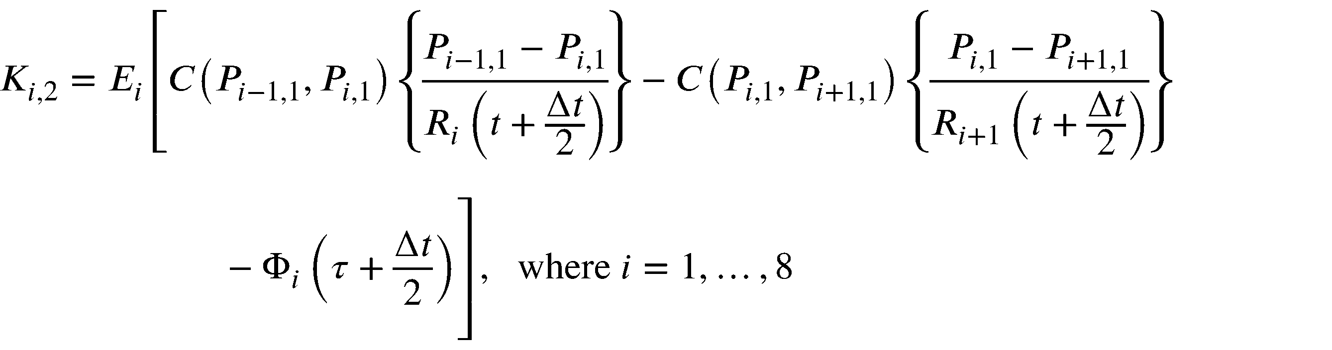
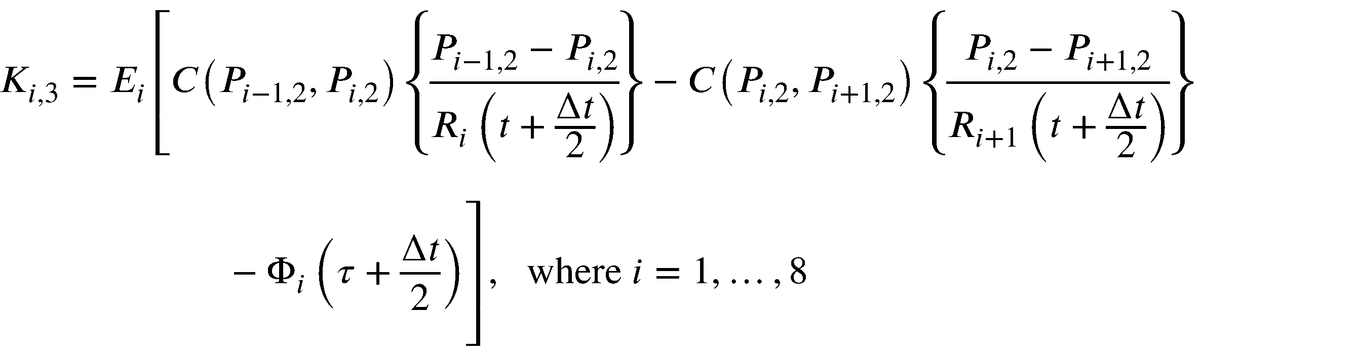


(動作)
次に、血圧推定装置1の動作について説明する。
検出部10は、所定の検出周期(例えば、1秒)が経過する毎に、脈拍数及び脈拍振幅を検出する。
また、処理部20は、図8に表される処理を実行する。以下、図8の処理について説明を加える。
次に、血圧推定装置1の動作について説明する。
検出部10は、所定の検出周期(例えば、1秒)が経過する毎に、脈拍数及び脈拍振幅を検出する。
また、処理部20は、図8に表される処理を実行する。以下、図8の処理について説明を加える。
処理部20は、時間t、圧力P1~P8、及び、抵抗R1~R8を、初期値tini、初期値P1,ini~P8,ini、及び、初期値R1,ini~R8,iniにそれぞれ設定する(図8のステップS101)。
次いで、処理部20は、検出部10により検出された脈拍数及び脈拍振幅に基づいて、時間tにおける脈拍数b(t)及び脈拍振幅a(t)を取得する(図8のステップS102)。
次いで、処理部20は、検出部10により検出された脈拍数及び脈拍振幅に基づいて、時間tにおける脈拍数b(t)及び脈拍振幅a(t)を取得する(図8のステップS102)。
そして、処理部20は、記憶部201に記憶されている基準目標抵抗gi,0と、ステップS102にて取得された脈拍数b(t)及び脈拍振幅a(t)と、に基づいて、目標抵抗giを算出する(図8のステップS103)。本例では、処理部20は、記憶部201に記憶されている基準目標抵抗gi,0と、記憶部201に記憶されている基準目標抵抗比γiと、ステップS102にて取得された脈拍数b(t)及び脈拍振幅a(t)と、に基づいて、目標抵抗giを算出する。
次いで、処理部20は、ステップS102にて取得された脈拍数b(t)に基づいて、時間tにおける周期長τeを算出するとともに、周期開始時間t0を時間tに設定する(図8のステップS104)。
そして、処理部20は、時間tから、ステップS104にて設定された周期開始時間t0を減じた値を、周期内時間τとして算出する(図8のステップS105)。次いで、処理部20は、ステップS105にて算出された周期内時間τが、ステップS104にて算出された周期長τe以下であるか否かを判定する(図8のステップS106)。
先ず、周期内時間τが周期長τe以下である場合について説明する。この場合、処理部20は、「Yes」と判定し、図8のステップS107へ進む。そして、処理部20は、時間tからステップ時間Δtが経過した後の時間t+Δtにおける、第1乃至第8の連通管FC1~FC8のうちの、第4及び第8の連通管FC4,FC8以外の連通管FC1~FC3,FC5~FC7に対する抵抗R1(t+Δt)~R3(t+Δt),R5(t+Δt)~R7(t+Δt)を、時間tにおける抵抗R1(t)~R3(t),R5(t)~R7(t)にそれぞれ設定する。
更に、処理部20は、時間tからステップ時間Δtが経過した後の時間t+Δtにおける、第4及び第8の連通管FC4,FC8に対する抵抗R4(t+Δt),R8(t+Δt)を、ステップS103にて算出された目標抵抗giに基づいて算出する。加えて、処理部20は、ステップS108にて、便宜上、用いられる抵抗R9(t+Δt)を、第1の連通管FC1に対する抵抗R1(t+Δt)に設定する。
次いで、処理部20は、時間tからステップ時間Δtが経過した後の時間t+Δtにおける、第1乃至第8の容器FV1~FV8内の流体の圧力P1(t+Δt)~P8(t+Δt)を算出する(図8のステップS108)。ステップS108の処理は、後述される。
その後、処理部20は、時間tを、時間tからステップ時間Δtが経過した後の時間t+Δtに更新する(図8のステップS109)。そして、処理部20は、図8のステップS105へ戻り、周期内時間τが周期長τeよりも大きくなるまで、ステップS105からステップS109までの処理を繰り返し実行する。
周期内時間τが周期長τeよりも大きくなった場合、処理部20は、図8のステップS106にて「No」と判定し、図8のステップS102へ戻る。そして、処理部20は、ステップS109にて更新された時間tに対して、再び、ステップS102以降の処理を実行する。本例では、処理部20は、図8のステップS102に進んだ場合、検出部10により脈拍数及び脈拍振幅が検出された時間のうちの最新の時間が、ステップS109にて更新された時間tよりも先の(将来の)時間となるまで待機する。
図8のステップS108の処理について説明を加える。
処理部20は、図8のステップS108の処理として、図9及び図10に表される処理を実行する。以下、図9及び図10の処理について説明を加える。
処理部20は、図8のステップS108の処理として、図9及び図10に表される処理を実行する。以下、図9及び図10の処理について説明を加える。
処理部20は、第1乃至第8の容器FV1~FV8内の流体の圧力の暫定値である第1暫定圧力P1,0~P8,0を、時間tにおける、第1乃至第8の容器FV1~FV8内の流体の圧力P1(t)~P8(t)にそれぞれ設定する。
更に、処理部20は、便宜上、用いられる第1暫定圧力P0,0,P9,0を、第1暫定圧力P8,0,P1,0にそれぞれ設定する。加えて、処理部20は、第1暫定圧力P0,0~P9,0と、図8のステップS107にて算出された抵抗R1(t+Δt)~R9(t+Δt)と、周期内時間τにおける時間微分Φ1(τ)~Φ8(τ)と、に基づいて第1時間変化率K1,1~K8,1を算出する(図9のステップS201)。
次いで、処理部20は、第1乃至第8の容器FV1~FV8内の流体の圧力の暫定値である第2暫定圧力P1,1~P8,1を、時間tにおける、第1乃至第8の容器FV1~FV8内の流体の圧力P1(t)~P8(t)に、図9のステップS201にて算出された第1時間変化率K1,1~K8,1と、ステップ時間Δtを2により除した値と、の積をそれぞれ加えた値にそれぞれ設定する。
更に、処理部20は、便宜上、用いられる第2暫定圧力P0,1,P9,1を、第2暫定圧力P8,1,P1,1にそれぞれ設定する。加えて、処理部20は、第2暫定圧力P0,1~P9,1と、図8のステップS107にて算出された抵抗R1(t+Δt)~R9(t+Δt)と、周期内時間τよりもステップ時間Δtの半分の時間だけ後の時間τ+Δt/2における時間微分Φ1(τ+Δt/2)~Φ8(τ+Δt/2)と、に基づいて第2時間変化率K1,2~K8,2を算出する(図9のステップS202)。
次いで、処理部20は、第1乃至第8の容器FV1~FV8内の流体の圧力の暫定値である第3暫定圧力P1,2~P8,2を、時間tにおける、第1乃至第8の容器FV1~FV8内の流体の圧力P1(t)~P8(t)に、図9のステップS202にて算出された第2時間変化率K1,2~K8,2と、ステップ時間Δtを2により除した値と、の積をそれぞれ加えた値にそれぞれ設定する。
更に、処理部20は、便宜上、用いられる第3暫定圧力P0,2,P9,2を、第3暫定圧力P8,2,P1,2にそれぞれ設定する。加えて、処理部20は、第3暫定圧力P0,2~P9,2と、図8のステップS107にて算出された抵抗R1(t+Δt)~R9(t+Δt)と、周期内時間τよりもステップ時間Δtの半分の時間だけ後の時間τ+Δt/2における時間微分Φ1(τ+Δt/2)~Φ8(τ+Δt/2)と、に基づいて第3時間変化率K1,3~K8,3を算出する(図9のステップS203)。
次いで、処理部20は、第1乃至第8の容器FV1~FV8内の流体の圧力の暫定値である第4暫定圧力P1,3~P8,3を、時間tにおける、第1乃至第8の容器FV1~FV8内の流体の圧力P1(t)~P8(t)に、図9のステップS203にて算出された第3時間変化率K1,3~K8,3と、ステップ時間Δtと、の積をそれぞれ加えた値にそれぞれ設定する。
更に、処理部20は、便宜上、用いられる第4暫定圧力P0,3,P9,3を、第4暫定圧力P8,3,P1,3にそれぞれ設定する。加えて、処理部20は、第4暫定圧力P0,3~P9,3と、図8のステップS107にて算出された抵抗R1(t+Δt)~R9(t+Δt)と、周期内時間τよりもステップ時間Δtだけ後の時間τ+Δtにおける時間微分Φ1(τ+Δt)~Φ8(τ+Δt)と、に基づいて第4時間変化率K1,4~K8,4を算出する(図10のステップS204)。
そして、処理部20は、時間tにおける、第1乃至第8の容器FV1~FV8内の流体の圧力P1(t)~P8(t)と、ステップS201乃至ステップS204にてそれぞれ算出された第1乃至第4時間変化率K1,1~K8,1,K1,2~K8,2,K1,3~K8,3,K1,4~K8,4と、に基づいて、時間tからステップ時間Δtが経過した後の時間t+Δtにおける、第1乃至第8の容器FV1~FV8内の流体の圧力P1(t+Δt)~P8(t+Δt)を算出する(図10のステップS205)。
そして、処理部20は、図9及び図10の処理を終了する。
そして、処理部20は、図9及び図10の処理を終了する。
以上、説明したように、第1実施形態の血圧推定装置1は、生体の心拍の周期の長さである周期長を表す第1パラメータ(本例では、脈拍数b)を検出する。更に、血圧推定装置1は、弾性変形する複数の容器FV1~FV8が環状に連結された流路を流れる流体によって、生体の循環器系を流れる血液を表す数理モデルにおける、複数の容器FV1~FV8のうちの少なくとも1つの容器の無負荷容積の時間に対する変化(本例では、第2及び第6の容器FV2,FV6の無負荷容積V2,V6の時間微分Φ2,Φ6)を、検出された第1パラメータに基づいて決定する。加えて、血圧推定装置1は、決定された変化と、数理モデルと、に基づいて、生体の循環器系を流れる血液が有する圧力を推定する。
周期長を表す第1パラメータは、動脈径よりも高い精度にて検出されやすい。更に、第1パラメータに基づいて決定された、第2及び第6の容器FV2,FV6の無負荷容積V2,V6の時間に対する変化を用いることにより、上記数理モデルは、生体における左心室及び右心室の挙動を高い精度にて表すことができる。この結果、上記数理モデルは、生体の循環器系を流れる血液の挙動を高い精度にて表すことができる。従って、血圧推定装置1は、当該血液が有する圧力Piを高い精度にて推定できる。
更に、第1実施形態の血圧推定装置1は、複数の容器FV1~FV8のうちの、互いに連結された一対の容器間の流体の流量に対する、当該一対の容器における流体が有する圧力の容器間の差の比である抵抗(本例では、第4及び第8の連通管FC4,FC8に対する抵抗R4,R8)を、検出された第1パラメータに基づいて決定する。加えて、血圧推定装置1は、決定された抵抗に基づいて、生体の循環器系を流れる血液が有する圧力を推定する。
これによれば、抵抗R4,R8が一定に維持される場合よりも、上記数理モデルは、生体における末梢血管の挙動を高い精度にて表すことができる。これにより、上記数理モデルは、生体の循環器系を流れる血液の挙動を高い精度にて表すことができる。この結果、血圧推定装置1は、血液が有する圧力Piを高い精度にて推定できる。
更に、第1実施形態の血圧推定装置1は、抵抗(本例では、第4及び第8の連通管FC4,FC8に対する抵抗R4,R8)の目標値(本例では、目標抵抗g4,g8)を、検出された第1パラメータに基づいて決定する。加えて、血圧推定装置1は、抵抗が、決定された目標値に遅延を伴って近づくように抵抗の決定を行なう。
これによれば、上記数理モデルは、生体における末梢血管の挙動をより一層高い精度にて表すことができる。これにより、上記数理モデルは、生体の循環器系を流れる血液の挙動を高い精度にて表すことができる。この結果、血圧推定装置1は、生体の循環器系を流れる血液が有する圧力Piを高い精度にて推定できる。
更に、第1実施形態の血圧推定装置1は、心拍の大きさを表す第2パラメータ(本例では、脈拍振幅a)を検出する。加えて、血圧推定装置1は、検出された第2パラメータに基づいて、抵抗(本例では、第4及び第8の連通管FC4,FC8に対する抵抗R4,R8)の目標値(本例では、目標抵抗g4,g8)の決定を行なう。
ところで、心拍の大きさと、末梢血管における抵抗と、は強い相関を有する。従って、血圧推定装置1によれば、上記数理モデルは、生体における末梢血管の挙動をより一層高い精度にて表すことができる。これにより、上記数理モデルは、生体の循環器系を流れる血液の挙動を高い精度にて表すことができる。この結果、血圧推定装置1は、生体の循環器系を流れる血液が有する圧力Piを高い精度にて推定できる。
更に、第1実施形態の血圧推定装置1は、検出された第2パラメータに基づいて、複数の容器FV1~FV8のうちの少なくとも1つの容器の無負荷容積の時間に対する変化(本例では、第2及び第6の容器FV2,FV6の無負荷容積V2,V6の時間微分Φ2,Φ6)の決定を行なう。
ところで、心拍の大きさと、左心室及び右心室の容積と、は強い相関を有する。従って、血圧推定装置1によれば、上記数理モデルは、生体における左心室及び右心室の挙動をより一層高い精度にて表すことができる。これにより、上記数理モデルは、生体の循環器系を流れる血液の挙動を高い精度にて表すことができる。この結果、血圧推定装置1は、生体の循環器系を流れる血液が有する圧力Piを高い精度にて推定できる。
更に、第1実施形態の血圧推定装置1において、複数の容器FV1~FV8は、左心房、左心室、大動脈及び大動脈よりも下流側の動脈、大静脈及び大静脈よりも上流側の静脈、右心房、右心室、肺動脈、並びに、肺静脈をそれぞれ表す。
これによれば、上記数理モデルは、生体の循環器系を流れる血液の挙動を高い精度にて表すことができる。この結果、血圧推定装置1は、生体の循環器系を流れる血液が有する圧力Piを高い精度にて推定できる。
図11における曲線D11は、生体の安静時において血圧推定装置1により検出された脈拍数の一例を表す。図12乃至図14は、血圧推定装置1により検出された脈拍数が図11に表されるように変化した場合における、血圧推定装置1による推定結果の一例を表す。
図12における円D12,D13,D14は、比較例としての血圧測定装置により測定された最高血圧(換言すると、血圧の最高値)、最低血圧(換言すると、血圧の最低値)、及び、平均血圧(換言すると、血圧の平均値)をそれぞれ表す。本例では、血圧測定装置は、カフを用いることにより血圧を測定する。平均血圧は、最高血圧及び最低血圧を平均した値である。
図12における曲線E12,E13,E14は、血圧推定装置1により推定された最高血圧、最低血圧、及び、平均血圧をそれぞれ表す。図12に表されるように、第1実施形態の血圧推定装置1によれば、血圧を高い精度にて推定できる。
図13における曲線E15,E16は、第4の連通管FC4に対する抵抗R4の目標値g4、及び、第4の連通管FC4に対する抵抗R4をそれぞれ表す。
図14における四角D18は、比較例としての血圧測定装置により測定された最高血圧を表す。図14における円E18は、血圧推定装置1により推定された最高血圧を表す。図14に表されるように、第1実施形態の血圧推定装置1によれば、最高血圧と脈拍数との関係を高い精度にて推定できる。
図14における四角D18は、比較例としての血圧測定装置により測定された最高血圧を表す。図14における円E18は、血圧推定装置1により推定された最高血圧を表す。図14に表されるように、第1実施形態の血圧推定装置1によれば、最高血圧と脈拍数との関係を高い精度にて推定できる。
図15における曲線D21は、生体の運動時において血圧推定装置1により検出された脈拍数の一例を表す。図16乃至図18は、血圧推定装置1により検出された脈拍数が図15に表されるように変化した場合における、血圧推定装置1による推定結果の一例を表す。
図16における円D22,D23,D24は、比較例としての血圧測定装置により測定された最高血圧、最低血圧、及び、平均血圧をそれぞれ表す。本例では、血圧測定装置は、カフを用いることにより血圧を測定する。
図16における曲線E22,E23,E24は、血圧推定装置1により推定された最高血圧、最低血圧、及び、平均血圧をそれぞれ表す。図16に表されるように、第1実施形態の血圧推定装置1によれば、血圧を高い精度にて推定できる。
図17における曲線E25,E26は、第4の連通管FC4に対する抵抗R4の目標値g4、及び、第4の連通管FC4に対する抵抗R4をそれぞれ表す。
図18における四角D28は、比較例としての血圧測定装置により測定された最高血圧を表す。図18における円E28は、血圧推定装置1により推定された最高血圧を表す。図18に表されるように、第1実施形態の血圧推定装置1によれば、最高血圧と脈拍数との関係を高い精度にて推定できる。
図18における四角D28は、比較例としての血圧測定装置により測定された最高血圧を表す。図18における円E28は、血圧推定装置1により推定された最高血圧を表す。図18に表されるように、第1実施形態の血圧推定装置1によれば、最高血圧と脈拍数との関係を高い精度にて推定できる。
なお、血圧推定装置1は、検出部10を構成する第1の装置と、処理部20を構成する第2の装置と、を備えていてもよい。この場合、第1の装置と第2の装置とは、互いに通信可能に接続される。この場合、第2の装置は、携帯電話機、スマートフォン、パーソナル・コンピュータ、又は、サーバ装置であってよい。
また、上述したように、血圧推定装置1は、脈拍数の検出と、脈拍数が検出された時間における血圧の推定と、を並列に行なう。ところで、血圧推定装置1は、所定の期間における脈拍数の検出が終了した後に、当該期間における血圧の推定を行なってもよい。
また、上述したように、血圧推定装置1は、複数の互いに異なる時間のそれぞれと、当該時間における圧力と、を関連付けて記憶する。ところで、血圧推定装置1は、記憶されている複数の時間のそれぞれと、記憶されている、当該時間における圧力と、を関連付けて出力してもよい。例えば、血圧推定装置1は、圧力の時間に対する変化を表すグラフを出力してもよい。
なお、処理部20は、第4及び第8の連通管FC4,FC8に対する抵抗R4,R8を、初期値R4,ini,R8,iniにそれぞれ設定するとともに、時間に対して変化させずに血圧を推定してもよい。
また、血圧推定装置1は、生体に対して予め測定された脈拍数及び血圧を表す情報が入力されるとともに、当該入力された情報に基づいて、基準目標抵抗gi,0、抵抗の初期値Ri,ini、及び、係数Eiの少なくとも1つを決定してもよい。
<第1実施形態の第1変形例>
次に、第1実施形態の第1変形例の血圧推定装置について説明する。第1実施形態の第1変形例の血圧推定装置は、第1実施形態の血圧推定装置に対して、生体の心拍の大きさを表す第2パラメータを第1パラメータに基づいて推定する点において相違している。以下、相違点を中心として説明する。なお、第1実施形態の第1変形例の説明において、第1実施形態にて使用した符号と同じ符号を付したものは、同一又はほぼ同様のものである。
次に、第1実施形態の第1変形例の血圧推定装置について説明する。第1実施形態の第1変形例の血圧推定装置は、第1実施形態の血圧推定装置に対して、生体の心拍の大きさを表す第2パラメータを第1パラメータに基づいて推定する点において相違している。以下、相違点を中心として説明する。なお、第1実施形態の第1変形例の説明において、第1実施形態にて使用した符号と同じ符号を付したものは、同一又はほぼ同様のものである。
本例では、処理部20は、検出部10により検出された脈拍数bと、数式27と、に基づいて脈拍振幅aを推定する。更に、処理部20は、推定された脈拍振幅aに基づいて、第2及び第6の容器FV2,FV6の無負荷容積f2,f6の決定、及び、第4及び第8の連通管FC4,FC8に対する目標抵抗g4,g8の算出を行なう。

hは、脈拍振幅aの目標値(換言すると、目標振幅)を表す。Taは、脈拍振幅aの変化の時定数を表す。時定数Taは、脈拍振幅aの変化が目標振幅hの変化に対して遅延する程度を表すと捉えられてよい。数式27に表されるように、脈拍振幅aは、目標振幅hに遅延を伴って近づくと捉えられてよい。目標振幅hは、脈拍数比b/b0に応じて予め定められた値を有する。本例では、目標振幅hは、図19により表されるように、脈拍数比b/b0が大きくなるにつれて増加する。
なお、血圧推定装置1は、生体に対して予め測定された脈拍数及び血圧を表す情報が入力されるとともに、当該入力された情報に基づいて、目標振幅hを決定してもよい。
推定部203は、検出部10により検出された脈拍数に基づいて、時間tにおける脈拍数b(t)を取得する。更に、推定部203は、数式27に対する差分方程式である数式28と、取得された脈拍数b(t)と、に基づいて、時間tからステップ時間Δtが経過した後の時間t+Δtにおける脈拍振幅a(t+Δt)を算出する。脈拍振幅aの算出は、脈拍振幅aの推定の一例である。

本例では、検出部10は、生体の心拍の大きさを表す第2パラメータを検出しなくてもよい。
第1実施形態の第1変形例の血圧推定装置1によれば、第1実施形態の血圧推定装置1と同様の作用及び効果が奏される。
第1実施形態の第1変形例の血圧推定装置1によれば、第1実施形態の血圧推定装置1と同様の作用及び効果が奏される。
図20乃至図22は、血圧推定装置1により検出された脈拍数が図11に表されるように変化した場合における、血圧推定装置1による推定結果の一例を表す。
図20における円D32,D33,D34は、比較例としての血圧測定装置により測定された最高血圧、最低血圧、及び、平均血圧をそれぞれ表す。本例では、血圧測定装置は、カフを用いることにより血圧を測定する。
図20における曲線E32,E33,E34は、血圧推定装置1により推定された最高血圧、最低血圧、及び、平均血圧をそれぞれ表す。図20に表されるように、第1実施形態の第1変形例の血圧推定装置1によれば、血圧を高い精度にて推定できる。
図21における曲線E35,E36は、第4の連通管FC4に対する抵抗R4の目標値g4、及び、第4の連通管FC4に対する抵抗R4をそれぞれ表す。
図22における四角D38は、比較例としての血圧測定装置により測定された最高血圧を表す。図22における円E38は、血圧推定装置1により推定された最高血圧を表す。図22に表されるように、第1実施形態の第1変形例の血圧推定装置1によれば、最高血圧と脈拍数との関係を高い精度にて推定できる。
図22における四角D38は、比較例としての血圧測定装置により測定された最高血圧を表す。図22における円E38は、血圧推定装置1により推定された最高血圧を表す。図22に表されるように、第1実施形態の第1変形例の血圧推定装置1によれば、最高血圧と脈拍数との関係を高い精度にて推定できる。
図23乃至図25は、血圧推定装置1により検出された脈拍数が図15に表されるように変化した場合における、血圧推定装置1による推定結果の一例を表す。
図23における円D42,D43,D44は、比較例としての血圧測定装置により測定された最高血圧、最低血圧、及び、平均血圧をそれぞれ表す。本例では、血圧測定装置は、カフを用いることにより血圧を測定する。
図23における曲線E42,E43,E44は、血圧推定装置1により推定された最高血圧、最低血圧、及び、平均血圧をそれぞれ表す。図23に表されるように、第1実施形態の第1変形例の血圧推定装置1によれば、血圧を高い精度にて推定できる。
図24における曲線E45,E46は、第4の連通管FC4に対する抵抗R4の目標値g4、及び、第4の連通管FC4に対する抵抗R4をそれぞれ表す。
図25における四角D48は、比較例としての血圧測定装置により測定された最高血圧を表す。図25における円E48は、血圧推定装置1により推定された最高血圧を表す。図25に表されるように、第1実施形態の第1変形例の血圧推定装置1によれば、最高血圧と脈拍数との関係を高い精度にて推定できる。
図25における四角D48は、比較例としての血圧測定装置により測定された最高血圧を表す。図25における円E48は、血圧推定装置1により推定された最高血圧を表す。図25に表されるように、第1実施形態の第1変形例の血圧推定装置1によれば、最高血圧と脈拍数との関係を高い精度にて推定できる。
<第1実施形態の第2変形例>
次に、第1実施形態の第2変形例の血圧推定装置について説明する。第1実施形態の第2変形例の血圧推定装置は、第1実施形態の第1変形例の血圧推定装置に対して、所定の関数を用いて、基準目標抵抗gi,0、基準目標抵抗比γi、生体の安静時における第4の連通管FC4に対する抵抗R4,0、及び、第4の容器FV4に関連付けられた係数E4を算出する点において相違している。以下、相違点を中心として説明する。なお、第1実施形態の第2変形例の説明において、第1実施形態の第1変形例にて使用した符号と同じ符号を付したものは、同一又はほぼ同様のものである。
次に、第1実施形態の第2変形例の血圧推定装置について説明する。第1実施形態の第2変形例の血圧推定装置は、第1実施形態の第1変形例の血圧推定装置に対して、所定の関数を用いて、基準目標抵抗gi,0、基準目標抵抗比γi、生体の安静時における第4の連通管FC4に対する抵抗R4,0、及び、第4の容器FV4に関連付けられた係数E4を算出する点において相違している。以下、相違点を中心として説明する。なお、第1実施形態の第2変形例の説明において、第1実施形態の第1変形例にて使用した符号と同じ符号を付したものは、同一又はほぼ同様のものである。
処理部20は、基準目標抵抗比γiの記憶に代えて、基準目標抵抗比γiを算出する関数を記憶する。本例では、処理部20は、基準目標抵抗比γiを算出する関数として、数式29により表される関数を記憶する。処理部20は、数式29に基づいて基準目標抵抗比γiを算出する。

更に、処理部20は、基準目標抵抗gi,0の記憶に代えて、基準目標抵抗gi,0を算出する関数を記憶する。本例では、処理部20は、基準目標抵抗gi,0を算出する関数として、数式30により表される関数を記憶する。処理部20は、数式30に基づいて基準目標抵抗gi,0を算出する。

Ri,0は、生体の安静時における第iの連通管FCiに対する抵抗を表す。本例では、処理部20は、生体の安静時における第4の連通管FC4に対する抵抗R4,0を、脈拍数bの基準値b0と、生体の安静時において測定された最高血圧Psmaxと、生体の安静時において測定された最低血圧Psminと、所定の係数αと、数式31と、に基づいて算出する。例えば、脈拍数bの基準値b0は、生体の安静時において測定された脈拍数である。なお、係数αは、血圧の推定が実行される毎に変更されてもよい。また、係数αは、生体に応じた値に設定されてもよい。

本例では、処理部20は、第4の容器FV4に関連付けられた係数E4を、生体の安静時において測定された最高血圧Psmaxと、生体の安静時において測定された最低血圧Psminと、所定の係数βと、数式32と、に基づいて算出する。なお、係数βは、血圧の推定が実行される毎に変更されてもよい。また、係数βは、生体に応じた値に設定されてもよい。

本例では、処理部20は、第8の連通管FC8に対する抵抗R8,0として、固定された値(換言すると、複数の異なる生体に対して共通する値)を用いる。なお、第8の連通管FC8に対する抵抗R8,0は、血圧の推定が実行される毎に変更されてもよい。また、第8の連通管FC8に対する抵抗R8,0は、生体に応じた値に設定されてもよい。
また、本例では、処理部20は、第jの容器FVjに関連付けられた係数Ejとして、固定された値を用いる。jは、1から8の整数のうちの4以外の各整数を表す。なお、第jの容器FVjに関連付けられた係数Ejは、血圧の推定が実行される毎に変更されてもよい。また、第jの容器FVjに関連付けられた係数Ejは、生体に応じた値に設定されてもよい。
第1実施形態の第2変形例の血圧推定装置1によれば、第1実施形態の第1変形例の血圧推定装置1と同様の作用及び効果が奏される。
図26乃至図29は、血圧推定装置1により検出された脈拍数が図11に表されるように変化した場合における、血圧推定装置1による推定結果の一例を表す。
図26における円D92,D93,D94は、比較例としての血圧測定装置により測定された最高血圧、最低血圧、及び、平均血圧をそれぞれ表す。本例では、血圧測定装置は、カフを用いることにより血圧を測定する。
図26における曲線E92,E93,E94は、血圧推定装置1により推定された最高血圧、最低血圧、及び、平均血圧をそれぞれ表す。図26に表されるように、第1実施形態の第2変形例の血圧推定装置1によれば、血圧を高い精度にて推定できる。
図27における曲線E95,E96は、第4の連通管FC4に対する抵抗R4の目標値g4、及び、第4の連通管FC4に対する抵抗R4をそれぞれ表す。
図28における四角D98は、比較例としての血圧測定装置により測定された最高血圧を表す。図28における円E98は、血圧推定装置1により推定された最高血圧を表す。図28に表されるように、第1実施形態の第2変形例の血圧推定装置1によれば、最高血圧と脈拍数との関係を高い精度にて推定できる。
図28における四角D98は、比較例としての血圧測定装置により測定された最高血圧を表す。図28における円E98は、血圧推定装置1により推定された最高血圧を表す。図28に表されるように、第1実施形態の第2変形例の血圧推定装置1によれば、最高血圧と脈拍数との関係を高い精度にて推定できる。
図29において、血圧測定装置により測定された血圧は、測定血圧と表されるとともに、血圧推定装置1により推定された血圧は、推定血圧と表される。図29における四角F91は、比較例としての血圧測定装置により測定された最高血圧と、血圧推定装置1により推定された最高血圧と、の関係を表す。図29における三角F92は、比較例としての血圧測定装置により測定された最低血圧と、血圧推定装置1により推定された最低血圧と、の関係を表す。図29における円F93は、比較例としての血圧測定装置により測定された平均血圧と、血圧推定装置1により推定された平均血圧と、の関係を表す。図29に表されるように、第1実施形態の第2変形例の血圧推定装置1によれば、最高血圧、最低血圧、及び、平均血圧を高い精度にて推定できる。
<第1実施形態の第3変形例>
次に、第1実施形態の第3変形例の血圧推定装置について説明する。第1実施形態の第3変形例の血圧推定装置は、第1実施形態の血圧推定装置に対して、生体の心拍の大きさを表す第2パラメータに基づかずに血圧を推定する点において相違している。以下、相違点を中心として説明する。なお、第1実施形態の第3変形例の説明において、第1実施形態にて使用した符号と同じ符号を付したものは、同一又はほぼ同様のものである。
次に、第1実施形態の第3変形例の血圧推定装置について説明する。第1実施形態の第3変形例の血圧推定装置は、第1実施形態の血圧推定装置に対して、生体の心拍の大きさを表す第2パラメータに基づかずに血圧を推定する点において相違している。以下、相違点を中心として説明する。なお、第1実施形態の第3変形例の説明において、第1実施形態にて使用した符号と同じ符号を付したものは、同一又はほぼ同様のものである。
処理部20は、時間tにおける脈拍振幅a(t)に代えて、脈拍振幅aの基準値a0を用いる。換言すると、本例では、第2及び第6の容器FV2,FV6の無負荷容積f2,f6は、数式3に代わる数式33により表される。

また、第4及び第8の連通管FC4,FC8に対する抵抗R4,R8の目標値g4,g8は、数式9に代わる数式34により表される。

本例では、検出部10は、生体の心拍の大きさを表す第2パラメータを検出しなくてもよい。
第1実施形態の第3変形例の血圧推定装置1によれば、第1実施形態の血圧推定装置1と同様の作用及び効果が奏される。
第1実施形態の第3変形例の血圧推定装置1によれば、第1実施形態の血圧推定装置1と同様の作用及び効果が奏される。
図30乃至図32は、血圧推定装置1により検出された脈拍数が図11に表されるように変化した場合における、血圧推定装置1による推定結果の一例を表す。
図30における円D52,D53,D54は、比較例としての血圧測定装置により測定された最高血圧、最低血圧、及び、平均血圧をそれぞれ表す。本例では、血圧測定装置は、カフを用いることにより血圧を測定する。
図30における曲線E52,E53,E54は、血圧推定装置1により推定された最高血圧、最低血圧、及び、平均血圧をそれぞれ表す。図30に表されるように、第1実施形態の第3変形例の血圧推定装置1によれば、血圧を高い精度にて推定できる。
図31における曲線E55,E56は、第4の連通管FC4に対する抵抗R4の目標値g4、及び、第4の連通管FC4に対する抵抗R4をそれぞれ表す。
図32における四角D58は、比較例としての血圧測定装置により測定された最高血圧を表す。図32における円E58は、血圧推定装置1により推定された最高血圧を表す。図32に表されるように、第1実施形態の第3変形例の血圧推定装置1によれば、最高血圧と脈拍数との関係を高い精度にて推定できる。
図32における四角D58は、比較例としての血圧測定装置により測定された最高血圧を表す。図32における円E58は、血圧推定装置1により推定された最高血圧を表す。図32に表されるように、第1実施形態の第3変形例の血圧推定装置1によれば、最高血圧と脈拍数との関係を高い精度にて推定できる。
図33乃至図35は、血圧推定装置1により検出された脈拍数が図15に表されるように変化した場合における、血圧推定装置1による推定結果の一例を表す。
図33における円D62,D63,D64は、比較例としての血圧測定装置により測定された最高血圧、最低血圧、及び、平均血圧をそれぞれ表す。本例では、血圧測定装置は、カフを用いることにより血圧を測定する。
図33における曲線E62,E63,E64は、血圧推定装置1により推定された最高血圧、最低血圧、及び、平均血圧をそれぞれ表す。図33に表されるように、第1実施形態の第3変形例の血圧推定装置1によれば、血圧を高い精度にて推定できる。
図34における曲線E65,E66は、第4の連通管FC4に対する抵抗R4の目標値g4、及び、第4の連通管FC4に対する抵抗R4をそれぞれ表す。
図35における四角D68は、比較例としての血圧測定装置により測定された最高血圧を表す。図35における円E68は、血圧推定装置1により推定された最高血圧を表す。図35に表されるように、第1実施形態の第3変形例の血圧推定装置1によれば、最高血圧と脈拍数との関係を高い精度にて推定できる。
図35における四角D68は、比較例としての血圧測定装置により測定された最高血圧を表す。図35における円E68は、血圧推定装置1により推定された最高血圧を表す。図35に表されるように、第1実施形態の第3変形例の血圧推定装置1によれば、最高血圧と脈拍数との関係を高い精度にて推定できる。
<第1実施形態の第4変形例>
次に、第1実施形態の第4変形例の血圧推定装置について説明する。第1実施形態の第4変形例の血圧推定装置は、第1実施形態の第3変形例の血圧推定装置に対して、抵抗を時間に対して変化させずに血圧を推定する点において相違している。以下、相違点を中心として説明する。なお、第1実施形態の第4変形例の説明において、第1実施形態にて使用した符号と同じ符号を付したものは、同一又はほぼ同様のものである。
次に、第1実施形態の第4変形例の血圧推定装置について説明する。第1実施形態の第4変形例の血圧推定装置は、第1実施形態の第3変形例の血圧推定装置に対して、抵抗を時間に対して変化させずに血圧を推定する点において相違している。以下、相違点を中心として説明する。なお、第1実施形態の第4変形例の説明において、第1実施形態にて使用した符号と同じ符号を付したものは、同一又はほぼ同様のものである。
処理部20は、第4及び第8の連通管FC4,FC8に対する抵抗R4,R8を、初期値R4,ini,R8,iniにそれぞれ設定するとともに、時間に対して変化させない。
第1実施形態の第4変形例の血圧推定装置1によれば、第1実施形態の血圧推定装置1と同様の作用及び効果が奏される。
第1実施形態の第4変形例の血圧推定装置1によれば、第1実施形態の血圧推定装置1と同様の作用及び効果が奏される。
図36乃至図38は、血圧推定装置1により検出された脈拍数が図11に表されるように変化した場合における、血圧推定装置1による推定結果の一例を表す。
図36における円D72,D73,D74は、比較例としての血圧測定装置により測定された最高血圧、最低血圧、及び、平均血圧をそれぞれ表す。本例では、血圧測定装置は、カフを用いることにより血圧を測定する。
図36における曲線E72,E73,E74は、血圧推定装置1により推定された最高血圧、最低血圧、及び、平均血圧をそれぞれ表す。図36に表されるように、第1実施形態の第4変形例の血圧推定装置1によれば、血圧を高い精度にて推定できる。
図37における曲線E76は、第4の連通管FC4に対する抵抗R4を表す。
図38における四角D78は、比較例としての血圧測定装置により測定された最高血圧を表す。図38における円E78は、血圧推定装置1により推定された最高血圧を表す。図38に表されるように、第1実施形態の第4変形例の血圧推定装置1によれば、最高血圧と脈拍数との関係を高い精度にて推定できる。
図38における四角D78は、比較例としての血圧測定装置により測定された最高血圧を表す。図38における円E78は、血圧推定装置1により推定された最高血圧を表す。図38に表されるように、第1実施形態の第4変形例の血圧推定装置1によれば、最高血圧と脈拍数との関係を高い精度にて推定できる。
図39乃至図41は、血圧推定装置1により検出された脈拍数が図15に表されるように変化した場合における、血圧推定装置1による推定結果の一例を表す。
図39における円D82,D83,D84は、比較例としての血圧測定装置により測定された最高血圧、最低血圧、及び、平均血圧をそれぞれ表す。本例では、血圧測定装置は、カフを用いることにより血圧を測定する。
図39における曲線E82,E83,E84は、血圧推定装置1により推定された最高血圧、最低血圧、及び、平均血圧をそれぞれ表す。図39に表されるように、第1実施形態の第4変形例の血圧推定装置1によれば、血圧を高い精度にて推定できる。
図40における曲線E86は、第4の連通管FC4に対する抵抗R4を表す。
図41における四角D88は、比較例としての血圧測定装置により測定された最高血圧を表す。図41における円E88は、血圧推定装置1により推定された最高血圧を表す。図41に表されるように、第1実施形態の第4変形例の血圧推定装置1によれば、最高血圧と脈拍数との関係を高い精度にて推定できる。
図41における四角D88は、比較例としての血圧測定装置により測定された最高血圧を表す。図41における円E88は、血圧推定装置1により推定された最高血圧を表す。図41に表されるように、第1実施形態の第4変形例の血圧推定装置1によれば、最高血圧と脈拍数との関係を高い精度にて推定できる。
なお、本発明は、上述した実施形態に限定されない。例えば、上述した実施形態に、本発明の趣旨を逸脱しない範囲内において当業者が理解し得る様々な変更が加えられてよい。例えば、本発明の趣旨を逸脱しない範囲内において、上述した実施形態の他の変形例として、上述した実施形態及び変形例の任意の組み合わせが採用されてもよい。
1 血圧推定装置
10 検出部
20 処理部
21 処理装置
22 記憶装置
23 入力装置
24 出力装置
201 記憶部
202 決定部
203 推定部
BU バス
FC1~FC8 連通管
FV1~FV8 容器
10 検出部
20 処理部
21 処理装置
22 記憶装置
23 入力装置
24 出力装置
201 記憶部
202 決定部
203 推定部
BU バス
FC1~FC8 連通管
FV1~FV8 容器
Claims (12)
- 生体の心拍の周期の長さである周期長を表す第1パラメータを検出する検出部と、
弾性変形する複数の容器が環状に連結された流路を流れる流体によって、前記生体の循環器系を流れる血液を表す数理モデルにおける、前記複数の容器のうちの少なくとも1つの容器の容積の時間に対する変化を、前記検出された第1パラメータに基づいて決定し、前記決定された変化と、前記数理モデルと、に基づいて、前記血液が有する圧力を推定する処理部と、
を備える、血圧推定装置。 - 請求項1に記載の血圧推定装置であって、
前記処理部は、前記複数の容器のうちの、互いに連結された一対の容器間の前記流体の流量に対する、当該一対の容器における前記流体が有する圧力の容器間の差の比である抵抗を、前記検出された第1パラメータに基づいて決定し、前記決定された抵抗に基づいて、前記血液が有する圧力を推定する、血圧推定装置。 - 請求項2に記載の血圧推定装置であって、
前記処理部は、前記抵抗の目標値を、前記検出された第1パラメータに基づいて決定し、前記抵抗が、前記決定された目標値に遅延を伴って近づくように前記抵抗の前記決定を行なう、血圧推定装置。 - 請求項3に記載の血圧推定装置であって、
前記検出部は、前記心拍の大きさを表す第2パラメータを検出し、
前記処理部は、前記検出された第2パラメータに基づいて前記目標値の前記決定を行なう、血圧推定装置。 - 請求項1乃至請求項4のいずれか一項に記載の血圧推定装置であって、
前記検出部は、前記心拍の大きさを表す第2パラメータを検出し、
前記処理部は、前記検出された第2パラメータに基づいて、前記容積の時間に対する変化の前記決定を行なう、血圧推定装置。 - 請求項3に記載の血圧推定装置であって、
前記処理部は、前記検出された第1パラメータに基づいて、前記心拍の大きさを表す第2パラメータを推定し、前記推定された第2パラメータに基づいて前記目標値の前記決定を行なう、血圧推定装置。 - 請求項1乃至請求項6のいずれか一項に記載の血圧推定装置であって、
前記処理部は、前記検出された第1パラメータに基づいて、前記心拍の大きさを表す第2パラメータを推定し、前記推定された第2パラメータに基づいて、前記容積の時間に対する変化の前記決定を行なう、血圧推定装置。 - 請求項6又は請求項7に記載の血圧推定装置であって、
前記処理部は、前記第2パラメータの目標値を、前記検出された第1パラメータに基づいて決定し、前記第2パラメータが、前記決定された目標値に遅延を伴って近づくように前記第2パラメータの前記推定を行なう、血圧推定装置。 - 請求項1乃至請求項8のいずれか一項に記載の血圧推定装置であって、
前記複数の容器は、左心房、左心室、大動脈及び大動脈よりも下流側の動脈、大静脈及び大静脈よりも上流側の静脈、右心房、右心室、肺動脈、並びに、肺静脈をそれぞれ表す8個の容器を含む、血圧推定装置。 - 弾性変形する複数の容器が環状に連結された流路を流れる流体によって、生体の循環器系を流れる血液を表す数理モデルにおける、前記複数の容器のうちの少なくとも1つの容器の容積の時間に対する変化を、検出された、前記生体の心拍の周期の長さである周期長を表す第1パラメータに基づいて決定する決定部と、
前記決定された変化と、前記数理モデルと、に基づいて、前記血液が有する圧力を推定する推定部と、
を備える、情報処理装置。 - 弾性変形する複数の容器が環状に連結された流路を流れる流体によって、生体の循環器系を流れる血液を表す数理モデルにおける、前記複数の容器のうちの少なくとも1つの容器の容積の時間に対する変化を、検出された、前記生体の心拍の周期の長さである周期長を表す第1パラメータに基づいて決定し、
前記決定された変化と、前記数理モデルと、に基づいて、前記血液が有する圧力を推定する、血圧推定方法。 - 弾性変形する複数の容器が環状に連結された流路を流れる流体によって、生体の循環器系を流れる血液を表す数理モデルにおける、前記複数の容器のうちの少なくとも1つの容器の容積の時間に対する変化を、検出された、前記生体の心拍の周期の長さである周期長を表す第1パラメータに基づいて決定し、
前記決定された変化と、前記数理モデルと、に基づいて、前記血液が有する圧力を推定する、処理をコンピュータに実行させる血圧推定プログラム。
Priority Applications (2)
| Application Number | Priority Date | Filing Date | Title |
|---|---|---|---|
| JP2017551876A JP6580158B2 (ja) | 2015-11-17 | 2016-11-15 | 血圧推定装置、情報処理装置、血圧推定方法、及び、血圧推定プログラム |
| US15/981,075 US11284805B2 (en) | 2015-11-17 | 2018-05-16 | Blood pressure estimating apparatus, method for estimating blood pressure, and non-transitory computer-readable recording medium having stored therein program for estimating blood pressure |
Applications Claiming Priority (2)
| Application Number | Priority Date | Filing Date | Title |
|---|---|---|---|
| JP2015-224729 | 2015-11-17 | ||
| JP2015224729 | 2015-11-17 |
Related Child Applications (1)
| Application Number | Title | Priority Date | Filing Date |
|---|---|---|---|
| US15/981,075 Continuation US11284805B2 (en) | 2015-11-17 | 2018-05-16 | Blood pressure estimating apparatus, method for estimating blood pressure, and non-transitory computer-readable recording medium having stored therein program for estimating blood pressure |
Publications (1)
| Publication Number | Publication Date |
|---|---|
| WO2017086294A1 true WO2017086294A1 (ja) | 2017-05-26 |
Family
ID=58718955
Family Applications (1)
| Application Number | Title | Priority Date | Filing Date |
|---|---|---|---|
| PCT/JP2016/083770 Ceased WO2017086294A1 (ja) | 2015-11-17 | 2016-11-15 | 血圧推定装置、情報処理装置、血圧推定方法、及び、血圧推定プログラム |
Country Status (3)
| Country | Link |
|---|---|
| US (1) | US11284805B2 (ja) |
| JP (1) | JP6580158B2 (ja) |
| WO (1) | WO2017086294A1 (ja) |
Cited By (1)
| Publication number | Priority date | Publication date | Assignee | Title |
|---|---|---|---|---|
| JP6847489B1 (ja) * | 2019-11-05 | 2021-03-24 | 国立大学法人東北大学 | 血圧推定装置、血圧推定方法、及び、血圧推定プログラム |
Families Citing this family (2)
| Publication number | Priority date | Publication date | Assignee | Title |
|---|---|---|---|---|
| WO2021044571A1 (ja) * | 2019-09-05 | 2021-03-11 | 株式会社日立国際電気 | 脈拍数推定方法、装置およびシステム |
| DE102019214343A1 (de) * | 2019-09-20 | 2021-03-25 | Robert Bosch Gmbh | Verfahren zum Ausgleichen von Ladezuständen eines elektrischen Energiespeichers |
Citations (4)
| Publication number | Priority date | Publication date | Assignee | Title |
|---|---|---|---|---|
| JP2007029137A (ja) * | 2005-07-22 | 2007-02-08 | Seiko Instruments Inc | 血液レオロジー測定装置 |
| JP2008512177A (ja) * | 2004-09-13 | 2008-04-24 | ガンブロ・ルンディア・エービー | 急激な血圧変化の検知 |
| WO2013005320A1 (ja) * | 2011-07-06 | 2013-01-10 | パイオニア株式会社 | 血圧低下予測装置 |
| JP2013132407A (ja) * | 2011-12-27 | 2013-07-08 | Tohoku Univ | 連続血圧測定システム、連続血圧測定方法、連続血圧測定プログラムおよび、連続血圧測定プログラムを記録したコンピュータ読み取り可能な記録媒体 |
Family Cites Families (13)
| Publication number | Priority date | Publication date | Assignee | Title |
|---|---|---|---|---|
| US3893452A (en) * | 1974-07-09 | 1975-07-08 | Medtronic Inc | Blood pressure monitoring system |
| US5423322A (en) * | 1988-12-29 | 1995-06-13 | Medical Physics, Inc. | Total compliance method and apparatus for noninvasive arterial blood pressure measurement |
| US5140990A (en) * | 1990-09-06 | 1992-08-25 | Spacelabs, Inc. | Method of measuring blood pressure with a photoplethysmograph |
| JP3465133B2 (ja) * | 1997-08-05 | 2003-11-10 | 日本光電工業株式会社 | 患者監視装置 |
| WO2000072750A1 (en) | 1999-06-01 | 2000-12-07 | Massachusetts Institute Of Technology | Cuffless continuous blood pressure monitor |
| CA2388033A1 (en) * | 1999-10-07 | 2001-04-12 | Alexander K. Mills | Device and method for noninvasive continuous determination of physiologic characteristics |
| JP4206218B2 (ja) * | 2002-04-03 | 2009-01-07 | セイコーインスツル株式会社 | 循環動態測定装置 |
| JP4581050B2 (ja) * | 2006-02-16 | 2010-11-17 | 財団法人ヒューマンサイエンス振興財団 | 心臓酸素消費量自動最小化システムおよびこれを用いた心疾患治療システム |
| US7654964B1 (en) * | 2006-03-16 | 2010-02-02 | Pacesetter, Inc. | System and method for detecting arterial blood pressure based on aortic electrical resistance using an implantable medical device |
| WO2008144404A1 (en) * | 2007-05-16 | 2008-11-27 | Massachusetts Instutute Of Technology | Systems and methods for model-based estimation of cardiac output and total peripheral resistance |
| WO2010005536A2 (en) * | 2008-07-08 | 2010-01-14 | The Johns Hopkins University | Non-invasive methods and systems for assessing cardiac filing pressure |
| GB201119982D0 (en) * | 2011-11-18 | 2012-01-04 | Maarek Albert | Medical device and measurement of cardiac output |
| US9522317B2 (en) * | 2011-08-19 | 2016-12-20 | Pulson, Inc. | Systems and methods for coordinating musculoskeletal and cardiovascular or cerebrovascular hemodynamics |
-
2016
- 2016-11-15 JP JP2017551876A patent/JP6580158B2/ja active Active
- 2016-11-15 WO PCT/JP2016/083770 patent/WO2017086294A1/ja not_active Ceased
-
2018
- 2018-05-16 US US15/981,075 patent/US11284805B2/en active Active
Patent Citations (4)
| Publication number | Priority date | Publication date | Assignee | Title |
|---|---|---|---|---|
| JP2008512177A (ja) * | 2004-09-13 | 2008-04-24 | ガンブロ・ルンディア・エービー | 急激な血圧変化の検知 |
| JP2007029137A (ja) * | 2005-07-22 | 2007-02-08 | Seiko Instruments Inc | 血液レオロジー測定装置 |
| WO2013005320A1 (ja) * | 2011-07-06 | 2013-01-10 | パイオニア株式会社 | 血圧低下予測装置 |
| JP2013132407A (ja) * | 2011-12-27 | 2013-07-08 | Tohoku Univ | 連続血圧測定システム、連続血圧測定方法、連続血圧測定プログラムおよび、連続血圧測定プログラムを記録したコンピュータ読み取り可能な記録媒体 |
Cited By (2)
| Publication number | Priority date | Publication date | Assignee | Title |
|---|---|---|---|---|
| JP6847489B1 (ja) * | 2019-11-05 | 2021-03-24 | 国立大学法人東北大学 | 血圧推定装置、血圧推定方法、及び、血圧推定プログラム |
| WO2021090779A1 (ja) * | 2019-11-05 | 2021-05-14 | 国立大学法人東北大学 | 血圧推定装置、血圧推定方法、及び、血圧推定プログラム |
Also Published As
| Publication number | Publication date |
|---|---|
| JPWO2017086294A1 (ja) | 2018-09-06 |
| JP6580158B2 (ja) | 2019-09-25 |
| US11284805B2 (en) | 2022-03-29 |
| US20180263514A1 (en) | 2018-09-20 |
Similar Documents
| Publication | Publication Date | Title |
|---|---|---|
| JP6494664B2 (ja) | 血圧測定デバイスの連続キャリブレーション | |
| CN107847649B (zh) | 用于处理心脏传感器输出的方法和计算机系统 | |
| CN104116503B (zh) | 一种无创连续血压的测量装置 | |
| JP6580158B2 (ja) | 血圧推定装置、情報処理装置、血圧推定方法、及び、血圧推定プログラム | |
| WO2009099833A2 (en) | Real-time detection of vascular conditions of a subject using arterial pressure waveform analysis | |
| JP2014158956A (ja) | 動脈圧波形データを用いた血管症状の検出 | |
| CN102387743A (zh) | 计算心血管参数 | |
| JP2016508386A5 (ja) | ||
| WO2018072212A1 (zh) | 血压测量设备的校准方法及血压测量设备 | |
| CN108245148A (zh) | 自适应生物信号特征组合设备及方法 | |
| JP2016123424A (ja) | 血圧測定システムおよび血行パラメータ決定方法 | |
| JP2019510598A5 (ja) | ||
| CN109872820A (zh) | 一种无袖带血压测量方法、装置、设备及存储介质 | |
| CN107898443A (zh) | 重搏波检测方法、装置及计算机存储介质 | |
| WO2015006191A1 (en) | Arterial pressure-based determination of cardiovascular parameters | |
| US10610166B2 (en) | Determination of a hemodynamic parameter | |
| JP2020505177A (ja) | 向上した心拍出量測定を提供する血流力学モニター | |
| JP5940652B2 (ja) | 体調監視装置及び方法 | |
| Banerjee et al. | HeartSense: smart phones to estimate blood pressure from photoplethysmography | |
| EP2416701A2 (en) | Monitoring peripheral decoupling | |
| JP6847489B1 (ja) | 血圧推定装置、血圧推定方法、及び、血圧推定プログラム | |
| JP2016209020A5 (ja) | ||
| WO2016039241A1 (ja) | トレーニングに好適なランニング強度の推定方法、およびランニング支援装置 | |
| JP6806254B2 (ja) | 特定装置、特定方法、及び、特定プログラム | |
| CN118267604B (zh) | 基于左心室辅助设备的剩余心脏收缩力估计方法及系统 |
Legal Events
| Date | Code | Title | Description |
|---|---|---|---|
| 121 | Ep: the epo has been informed by wipo that ep was designated in this application |
Ref document number: 16866296 Country of ref document: EP Kind code of ref document: A1 |
|
| ENP | Entry into the national phase |
Ref document number: 2017551876 Country of ref document: JP Kind code of ref document: A |
|
| NENP | Non-entry into the national phase |
Ref country code: DE |
|
| 122 | Ep: pct application non-entry in european phase |
Ref document number: 16866296 Country of ref document: EP Kind code of ref document: A1 |