WO2017085859A1 - 空気調和装置 - Google Patents
空気調和装置 Download PDFInfo
- Publication number
- WO2017085859A1 WO2017085859A1 PCT/JP2015/082664 JP2015082664W WO2017085859A1 WO 2017085859 A1 WO2017085859 A1 WO 2017085859A1 JP 2015082664 W JP2015082664 W JP 2015082664W WO 2017085859 A1 WO2017085859 A1 WO 2017085859A1
- Authority
- WO
- WIPO (PCT)
- Prior art keywords
- heat
- heat medium
- refrigerant
- heat exchanger
- temperature
- Prior art date
Links
Images


Classifications
-
- F—MECHANICAL ENGINEERING; LIGHTING; HEATING; WEAPONS; BLASTING
- F25—REFRIGERATION OR COOLING; COMBINED HEATING AND REFRIGERATION SYSTEMS; HEAT PUMP SYSTEMS; MANUFACTURE OR STORAGE OF ICE; LIQUEFACTION SOLIDIFICATION OF GASES
- F25B—REFRIGERATION MACHINES, PLANTS OR SYSTEMS; COMBINED HEATING AND REFRIGERATION SYSTEMS; HEAT PUMP SYSTEMS
- F25B13/00—Compression machines, plants or systems, with reversible cycle
-
- F—MECHANICAL ENGINEERING; LIGHTING; HEATING; WEAPONS; BLASTING
- F24—HEATING; RANGES; VENTILATING
- F24F—AIR-CONDITIONING; AIR-HUMIDIFICATION; VENTILATION; USE OF AIR CURRENTS FOR SCREENING
- F24F11/00—Control or safety arrangements
- F24F11/89—Arrangement or mounting of control or safety devices
-
- F—MECHANICAL ENGINEERING; LIGHTING; HEATING; WEAPONS; BLASTING
- F25—REFRIGERATION OR COOLING; COMBINED HEATING AND REFRIGERATION SYSTEMS; HEAT PUMP SYSTEMS; MANUFACTURE OR STORAGE OF ICE; LIQUEFACTION SOLIDIFICATION OF GASES
- F25B—REFRIGERATION MACHINES, PLANTS OR SYSTEMS; COMBINED HEATING AND REFRIGERATION SYSTEMS; HEAT PUMP SYSTEMS
- F25B49/00—Arrangement or mounting of control or safety devices
- F25B49/02—Arrangement or mounting of control or safety devices for compression type machines, plants or systems
-
- F—MECHANICAL ENGINEERING; LIGHTING; HEATING; WEAPONS; BLASTING
- F25—REFRIGERATION OR COOLING; COMBINED HEATING AND REFRIGERATION SYSTEMS; HEAT PUMP SYSTEMS; MANUFACTURE OR STORAGE OF ICE; LIQUEFACTION SOLIDIFICATION OF GASES
- F25B—REFRIGERATION MACHINES, PLANTS OR SYSTEMS; COMBINED HEATING AND REFRIGERATION SYSTEMS; HEAT PUMP SYSTEMS
- F25B2313/00—Compression machines, plants or systems with reversible cycle not otherwise provided for
- F25B2313/003—Indoor unit with water as a heat sink or heat source
-
- F—MECHANICAL ENGINEERING; LIGHTING; HEATING; WEAPONS; BLASTING
- F25—REFRIGERATION OR COOLING; COMBINED HEATING AND REFRIGERATION SYSTEMS; HEAT PUMP SYSTEMS; MANUFACTURE OR STORAGE OF ICE; LIQUEFACTION SOLIDIFICATION OF GASES
- F25B—REFRIGERATION MACHINES, PLANTS OR SYSTEMS; COMBINED HEATING AND REFRIGERATION SYSTEMS; HEAT PUMP SYSTEMS
- F25B2313/00—Compression machines, plants or systems with reversible cycle not otherwise provided for
- F25B2313/006—Compression machines, plants or systems with reversible cycle not otherwise provided for two pipes connecting the outdoor side to the indoor side with multiple indoor units
-
- F—MECHANICAL ENGINEERING; LIGHTING; HEATING; WEAPONS; BLASTING
- F25—REFRIGERATION OR COOLING; COMBINED HEATING AND REFRIGERATION SYSTEMS; HEAT PUMP SYSTEMS; MANUFACTURE OR STORAGE OF ICE; LIQUEFACTION SOLIDIFICATION OF GASES
- F25B—REFRIGERATION MACHINES, PLANTS OR SYSTEMS; COMBINED HEATING AND REFRIGERATION SYSTEMS; HEAT PUMP SYSTEMS
- F25B2313/00—Compression machines, plants or systems with reversible cycle not otherwise provided for
- F25B2313/023—Compression machines, plants or systems with reversible cycle not otherwise provided for using multiple indoor units
- F25B2313/0231—Compression machines, plants or systems with reversible cycle not otherwise provided for using multiple indoor units with simultaneous cooling and heating
-
- F—MECHANICAL ENGINEERING; LIGHTING; HEATING; WEAPONS; BLASTING
- F25—REFRIGERATION OR COOLING; COMBINED HEATING AND REFRIGERATION SYSTEMS; HEAT PUMP SYSTEMS; MANUFACTURE OR STORAGE OF ICE; LIQUEFACTION SOLIDIFICATION OF GASES
- F25B—REFRIGERATION MACHINES, PLANTS OR SYSTEMS; COMBINED HEATING AND REFRIGERATION SYSTEMS; HEAT PUMP SYSTEMS
- F25B2313/00—Compression machines, plants or systems with reversible cycle not otherwise provided for
- F25B2313/023—Compression machines, plants or systems with reversible cycle not otherwise provided for using multiple indoor units
- F25B2313/0233—Compression machines, plants or systems with reversible cycle not otherwise provided for using multiple indoor units in parallel arrangements
-
- F—MECHANICAL ENGINEERING; LIGHTING; HEATING; WEAPONS; BLASTING
- F25—REFRIGERATION OR COOLING; COMBINED HEATING AND REFRIGERATION SYSTEMS; HEAT PUMP SYSTEMS; MANUFACTURE OR STORAGE OF ICE; LIQUEFACTION SOLIDIFICATION OF GASES
- F25B—REFRIGERATION MACHINES, PLANTS OR SYSTEMS; COMBINED HEATING AND REFRIGERATION SYSTEMS; HEAT PUMP SYSTEMS
- F25B2313/00—Compression machines, plants or systems with reversible cycle not otherwise provided for
- F25B2313/031—Sensor arrangements
- F25B2313/0314—Temperature sensors near the indoor heat exchanger
-
- F—MECHANICAL ENGINEERING; LIGHTING; HEATING; WEAPONS; BLASTING
- F25—REFRIGERATION OR COOLING; COMBINED HEATING AND REFRIGERATION SYSTEMS; HEAT PUMP SYSTEMS; MANUFACTURE OR STORAGE OF ICE; LIQUEFACTION SOLIDIFICATION OF GASES
- F25B—REFRIGERATION MACHINES, PLANTS OR SYSTEMS; COMBINED HEATING AND REFRIGERATION SYSTEMS; HEAT PUMP SYSTEMS
- F25B2400/00—General features or devices for refrigeration machines, plants or systems, combined heating and refrigeration systems or heat-pump systems, i.e. not limited to a particular subgroup of F25B
- F25B2400/24—Storage receiver heat
-
- F—MECHANICAL ENGINEERING; LIGHTING; HEATING; WEAPONS; BLASTING
- F25—REFRIGERATION OR COOLING; COMBINED HEATING AND REFRIGERATION SYSTEMS; HEAT PUMP SYSTEMS; MANUFACTURE OR STORAGE OF ICE; LIQUEFACTION SOLIDIFICATION OF GASES
- F25B—REFRIGERATION MACHINES, PLANTS OR SYSTEMS; COMBINED HEATING AND REFRIGERATION SYSTEMS; HEAT PUMP SYSTEMS
- F25B2700/00—Sensing or detecting of parameters; Sensors therefor
- F25B2700/21—Temperatures
Definitions
- the present invention relates to an air conditioner, and more particularly to an air conditioner applied to a multi air conditioner for buildings.
- an air conditioner such as a multi air conditioner for buildings
- a refrigerant is circulated between an outdoor unit that is a heat source unit arranged outside a building rooftop or the like and an indoor unit arranged inside a building or the like.
- the cooling operation or the heating operation is performed by transporting the cooling heat or the warm heat into the room.
- a refrigerant used in such an air conditioner for example, an HFC (hydrofluorocarbon) refrigerant is widely used.
- a natural refrigerant such as CO 2 (carbon dioxide).
- CO 2 carbon dioxide
- a chiller cold heat or heat is generated by a heat source device arranged outside the building. Then, a heat exchanger such as water or antifreeze liquid is heated or cooled by a heat exchanger arranged in the outdoor unit, and this is transferred to a fan coil unit, a panel heater or the like, which is an indoor unit, for cooling or heating.
- a heat exchanger such as water or antifreeze liquid is heated or cooled by a heat exchanger arranged in the outdoor unit, and this is transferred to a fan coil unit, a panel heater or the like, which is an indoor unit, for cooling or heating.
- the refrigerant In an air conditioner such as a chiller, the refrigerant is circulated only in the heat source unit arranged outdoors, and the refrigerant does not pass through the indoor unit. Therefore, the problem of refrigerant leakage into the room that occurs in an air conditioner that circulates a conventional HFC refrigerant does not occur.
- this air conditioner it is necessary to heat or cool a heat medium such as water or antifreeze liquid in a heat source unit outside the building and transport it to the indoor unit. Therefore, when the circulation path becomes long, the conveyance power becomes very large, and there is a problem that it is difficult to save energy.
- an intermediate heat exchanger that performs heat exchange between the refrigerant and a safe heat medium even when leaking into a room different from the refrigerant is provided, and the heat source machine and the intermediate heat exchange are provided.
- An air conditioner in which a refrigerant circulation circuit is configured with a heat exchanger and a heat medium circulation circuit is configured with an intermediate heat exchanger and an indoor unit has been proposed and put into practical use (see, for example, Patent Document 1 and Patent Document 2).
- the air conditioning apparatus described in Patent Document 2 includes a plurality of intermediate heat exchangers, and a cooling only operation mode in which the operation mode of all of the plurality of indoor units is cooling, or an operation mode of all of the plurality of indoor units.
- the heating only operation mode in which heating is performed it is possible to improve the heat exchange efficiency by switching the refrigerant circulation circuit so that all the intermediate heat exchangers perform heat exchange corresponding to cooling or heating.
- the cooling / heating mixed operation mode in which the operation mode varies depending on the indoor unit, it is necessary to divide a plurality of intermediate exchangers for cooling or heating, so that there is a problem that sufficient improvement in heat exchange efficiency cannot be achieved. there were.
- the present invention has been made in view of the above-described problems in the prior art, and in an air conditioner having an intermediate heat exchanger and having a refrigerant circulation circuit and a heat medium circulation circuit, improvement in air conditioning performance and It aims at providing the air conditioning apparatus which can aim at energy saving.
- An air conditioner includes a refrigerant circulation circuit that circulates a refrigerant by connecting a refrigerant side flow path of a compressor, a heat source side heat exchanger, a throttling device, and a first heat exchanger related to heat medium with a refrigerant pipe, A heat medium side flow path of the first heat exchanger between heat medium, a heat medium circulation circuit that connects the use side heat exchanger with a heat medium pipe to circulate the heat medium, and between the first heat medium
- An air conditioner for exchanging heat between the refrigerant and the heat medium in a heat exchanger comprising a heat storage tank having a heat storage tank for storing the heat medium, wherein the heat medium circulation circuit switches a flow path Accordingly, the heat storage tank is connected to the heat medium circulation circuit, and the heat medium flow switching device that enables the heat medium to flow into and out of the heat storage tank is provided.
- the heat accumulation tank is connected to the heat medium circulation circuit by switching the flow path, and the heat accumulation provided in the heat accumulation tank.
- FIG. 1 is a schematic diagram illustrating an example of a configuration of an air-conditioning apparatus 1 according to Embodiment 1 of the present invention.
- the air conditioning apparatus 1 includes an outdoor unit 10 as a heat source unit, a plurality of indoor units 20, an intermediate heat exchanger 30, a heat storage tank 40, and a control device 50.
- the example of FIG. 1 shows the case where two indoor units 20 are provided, the present invention is not limited to this, and for example, three or more indoor units 20 may be provided.
- the outdoor unit 10 is connected to the refrigerant side flow path of the intermediate heat exchanger 30 by two refrigerant pipes 2 through which refrigerant flows.
- the refrigerant circulation circuit 5 is formed by the outdoor unit 10, the intermediate heat exchanger 30, and the refrigerant pipe 2.
- the plurality of indoor units 20 are each connected to the heat medium side flow path of the intermediate heat exchanger 30 by two heat medium pipes 3 through which the heat medium flows.
- the heat storage tank 40 is connected to the heat medium side flow path of the intermediate heat exchanger 30 by two heat medium pipes 4 through which the heat medium flows.
- the heat medium circulation circuit 6 is formed by the plurality of indoor units 20, the intermediate heat exchanger 30, the heat storage tank 40, and the heat medium pipes 3 and 4.
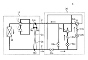
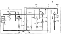
- FIG. 2 is a schematic diagram illustrating an example of a circuit configuration of the refrigerant circulation circuit 5 of the air-conditioning apparatus 1 according to Embodiment 1 of the present invention.
- the refrigerant circulation circuit 5 includes the outdoor unit 10, the intermediate heat exchanger 30, and the refrigerant pipe 2.
- the intermediate heat exchanger 30 has a portion related to the refrigerant circulation circuit 5 and a portion related to the heat medium circulation circuit 6. In the intermediate heat exchanger 30 shown in FIG. 2, only the portions related to the refrigerant circulation circuit 5 are illustrated and described.
- the outdoor unit 10 includes a compressor 11, a first refrigerant flow switching device 12, a heat source side heat exchanger 13, and four check valves 14a to 14d.
- the compressor 11 sucks a low-temperature and low-pressure refrigerant, compresses the refrigerant, and discharges it into a high-temperature and high-pressure gas refrigerant state.
- the compressor 11 for example, an inverter compressor or the like that can control the capacity that is the refrigerant delivery amount per unit time by arbitrarily changing the drive frequency can be used.
- the first refrigerant flow switching device 12 switches between a cooling operation and a heating operation by switching the direction in which the refrigerant flows.
- coolant flow path switching apparatus 12 shown in FIG. 2 shows the state at the time of heating operation.
- a four-way valve can be used, but other valves may be used in combination.
- the heat source side heat exchanger 13 performs heat exchange between air (hereinafter referred to as “outdoor air” as appropriate) supplied by a heat source side blower such as a fan (not shown) and the refrigerant.
- the heat source side heat exchanger 13 functions as a condenser that radiates the heat of the refrigerant to the outdoor air and condenses the refrigerant during the cooling operation and the defrosting operation.
- the heat source side heat exchanger 13 functions as an evaporator that evaporates the refrigerant during the heating operation and cools the outdoor air by the heat of vaporization at that time.
- the check valves 14a to 14d allow the flow of the refrigerant flowing through the refrigerant pipe 2 only in a predetermined direction.
- the check valve 14a is provided in the refrigerant pipe 2 between the intermediate heat exchanger 30 and the first refrigerant flow switching device 12, and intermediately heats the refrigerant during a cooling operation including a cooling only operation and a cooling main operation described later. Circulate in the direction from the exchanger 30 to the outdoor unit 10.
- the check valve 14b is provided in the first connection pipe 2a that connects the two refrigerant pipes 2, and the refrigerant returned from the intermediate heat exchanger 30 during the heating operation including the all heating operation and the heating main operation is compressed by the compressor. 11 is distributed to the suction side.
- the check valve 14 c is provided in the second connection pipe 2 b that connects the two refrigerant pipes 2, and causes the refrigerant discharged from the compressor 11 during the heating operation to flow to the intermediate heat exchanger 30.
- the check valve 14d is provided in the refrigerant pipe 2 between the heat source side heat exchanger 13 and the intermediate heat exchanger 30, and distributes the refrigerant in the direction from the outdoor unit 10 to the intermediate heat exchanger 30 during the cooling operation.
- the intermediate heat exchanger 30 includes two first heat exchangers 31a and 31b, two expansion devices 32a and 32b, two switch devices 33a and 33b, two second refrigerant flow switching devices 34a and 34b.
- the first heat exchangers 31 a and 31 b function as condensers or evaporators, and exchange heat between the refrigerant flowing through the refrigerant circulation circuit 5 and the heat medium flowing through the heat medium circulation circuit 6.
- the first heat exchanger related to heat medium 31a is provided between the expansion device 32a and the second refrigerant flow switching device 34a.
- the first heat exchanger related to heat medium 31b is provided between the expansion device 32b and the second refrigerant flow switching device 34b.
- the expansion devices 32a and 32b function as expansion valves that depressurize and expand the refrigerant flowing in the refrigerant circulation circuit 5.
- the expansion devices 32a and 32b are configured with valves capable of controlling the opening, such as an electronic expansion valve.
- the expansion device 32a is provided upstream of the first heat exchanger related to heat medium 31a in the refrigerant flow during the cooling only operation mode.
- the expansion device 32b is provided upstream of the first heat exchanger related to heat medium 31b in the refrigerant flow during the cooling only operation mode.
- the opening / closing devices 33a and 33b are, for example, two-way valves, and open / close the refrigerant pipe 2.
- the switchgear 33 a is provided in the refrigerant pipe 2 on the refrigerant inlet side in the intermediate heat exchanger 30.
- the opening / closing device 33 b is provided in a pipe connecting the refrigerant pipe 2 on the refrigerant inlet side and outlet side in the intermediate heat exchanger 30.
- the second refrigerant flow switching devices 34a and 34b switch the direction in which the refrigerant flows according to the operation mode.
- coolant flow path switching apparatus 34a and 34b shown in FIG. 2 show the state at the time of heating operation.
- a four-way valve can be used as the second refrigerant flow switching devices 34a and 34b, but other valves may be used in combination.
- the second refrigerant flow switching device 34a is provided on the downstream side of the first heat exchanger related to heat medium 31a in the refrigerant flow in the cooling only operation mode.
- the second refrigerant flow switching device 34b is provided on the downstream side of the first heat exchanger related to heat medium 31b in the refrigerant flow in the cooling only operation mode.
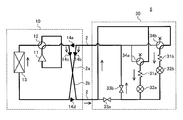
- FIG. 3 is a schematic diagram illustrating an example of a circuit configuration of the heat medium circulation circuit 6 of the air-conditioning apparatus 1 according to Embodiment 1 of the present invention.
- the heat medium circulation circuit 6 includes the plurality of indoor units 20a to 20c, the intermediate heat exchanger 30, the heat storage tank 40, and the heat medium pipes 3 and 4.
- the intermediate heat exchanger 30 shown in FIG. 3 only a part relevant to the heat medium circulation circuit 6 is illustrated and described. In this example, a case where three indoor units 20a to 20c are provided will be described. However, the number of indoor units 20 is not limited to this, and may be two or four or more, for example.
- the intermediate heat exchanger 30 includes two first heat exchangers 31a and 31b, two pumps 35a and 35b, two first heat medium flow switching devices 36a and 36b, and six second heats. It includes medium flow path switching devices 37a to 37f and four heat medium temperature sensors 38a to 38d.
- the pumps 35a and 35b are provided to circulate the heat medium flowing through at least one of the heat medium pipes 3 and 4.
- the pumps 35a and 35b are preferably constituted by, for example, pumps capable of capacity control, and the flow rate thereof can be adjusted according to the load of the indoor unit 20.
- the pump 35a is provided between the first heat exchanger related to heat medium 31a and the first heat medium flow switching device 36a.
- the pump 35b is provided in the heat medium pipe 3 between the first heat exchanger related to heat medium 31b and the first heat medium flow switching device 36b.
- the first heat medium flow switching devices 36a and 36b switch the direction in which the heat medium flows according to the use state of the heat storage tank 40 described later.
- the first heat medium flow switching devices 36a and 36b shown in FIG. 3 show a state where the heat storage tank 40 is not used.
- a four-way valve can be used as the first heat medium flow switching devices 36a and 36b, but other valves may be used in combination.
- the first heat medium flow switching device 36a is provided on the downstream side of the pump 35a.
- the first heat medium flow switching device 36b is provided on the downstream side of the pump 35b.
- the second heat medium flow switching devices 37a to 37f are, for example, three-way valves, and switch the direction in which the heat medium flows.
- the number of the second heat medium flow switching devices 37a to 37f is provided according to the number of the indoor units 20 provided in the air conditioner 1.
- the second heat medium flow switching device 37a is provided on the inlet side of the heat medium flow path of the use side heat exchanger 21a provided in the indoor unit 20a described later.
- one of the three sides is connected to the first heat medium flow switching device 36a, and one of the three sides is connected to the first heat medium flow switching device 36b.
- one of the three sides is connected to the use side heat exchanger 21a of the indoor unit 20a.
- the second heat medium flow switching device 37b is provided on the outlet side of the heat medium flow path of the use side heat exchanger 21a in the indoor unit 20a.
- one of the three sides is connected to the first heat exchanger related to heat medium 31a, and one of the three sides is connected to the first heat exchanger related to heat medium 31b. In addition, one of the three sides is connected to the use side heat exchanger 21a of the indoor unit 20a.
- the second heat medium flow switching device 37c is provided on the inlet side of the heat medium flow path of the use side heat exchanger 21b provided in the indoor unit 20b described later.
- one of the three sides is connected to the first heat medium flow switching device 36a, and one of the three sides is connected to the first heat medium flow switching device 36b.
- one of the three sides is connected to the use side heat exchanger 21b of the indoor unit 20b.
- the second heat medium flow switching device 37d is provided on the outlet side of the heat medium flow path of the use side heat exchanger 21b in the indoor unit 20b.
- one of the three sides is connected to the first heat exchanger related to heat medium 31a, and one of the three sides is connected to the first heat exchanger related to heat medium 31b. At the same time, one of the three sides is connected to the use side heat exchanger 21b of the indoor unit 20b.
- the second heat medium flow switching device 37e is provided on the inlet side of the heat medium flow path of the use side heat exchanger 21c provided in the indoor unit 20c described later.
- one of the three sides is connected to the first heat medium flow switching device 36a, and one of the three sides is connected to the first heat medium flow switching device 36b.
- one of the three sides is connected to the use side heat exchanger 21c of the indoor unit 20c.
- the second heat medium flow switching device 37f is provided on the outlet side of the heat medium flow path of the use side heat exchanger 21c in the indoor unit 20c.
- one of the three sides is connected to the first heat medium heat exchanger 31a, and one of the three directions is connected to the first heat medium heat exchanger 31b. At the same time, one of the three sides is connected to the use side heat exchanger 21c of the indoor unit 20c.
- the heat medium temperature sensors 38a to 38d are provided in the heat medium pipes 3 on the inlet side and the outlet side of the first heat exchanger related to heat medium 31a and the first heat exchanger related to heat medium 31b, respectively. Is detected.
- a thermistor can be used as the heat medium temperature sensors 38a to 38d.
- the heat medium temperature sensor 38a is provided in the heat medium pipe 3 on the outlet side of the first heat exchanger related to heat medium 31a, and detects the temperature of the heat medium flowing out from the first heat exchanger related to heat medium 31a.
- the heat medium temperature sensor 38b is provided in the heat medium pipe 3 on the inlet side of the first heat exchanger related to heat medium 31a, and detects the temperature of the heat medium flowing into the first heat exchanger related to heat medium 31a.
- the heat medium temperature sensor 38c is provided in the heat medium pipe 3 on the outlet side of the first heat exchanger related to heat medium 31b, and detects the temperature of the heat medium flowing out from the first heat exchanger related to heat medium 31b.
- the heat medium temperature sensor 38d is provided in the heat medium pipe 3 on the inlet side of the first heat exchanger related to heat medium 31b, and detects the temperature of the heat medium flowing into the first heat exchanger related to heat medium 31b.
- the temperature information obtained by these heat medium temperature sensors 38a to 38d is supplied to the control device 50 described later.
- the indoor units 20a to 20c perform, for example, cooling and heating of air in an indoor space (hereinafter referred to as “room air” as appropriate).
- the indoor unit 20a includes a use side heat exchanger 21a and an indoor temperature sensor 22a.
- the indoor unit 20b includes a use side heat exchanger 21b and an indoor temperature sensor 22b.
- the indoor unit 20c includes a use side heat exchanger 21c and an indoor temperature sensor 22c.
- the indoor units 20a to 20c are simply referred to as “indoor unit 20” when it is not necessary to distinguish them.
- the use side heat exchangers 21a to 21b are simply referred to as “use side heat exchanger 21”.
- the indoor temperature sensors 22a to 22c are simply referred to as “indoor temperature sensor 22”.
- the use side heat exchanger 21 performs heat exchange between indoor air and a heat medium supplied by a use side blower such as a fan (not shown). Thereby, heating air or cooling air supplied to the indoor space is generated.
- the use-side heat exchanger 21 functions as an evaporator when the heat medium carries cold heat during the cooling operation, and cools the indoor air by cooling it.
- the utilization side heat exchanger 21 functions as a condenser when the heat medium conveys warm heat during heating operation, and heats indoor air to perform heating.
- Each of the indoor temperature sensors 22 is provided at a predetermined position with respect to the indoor unit 20.
- the indoor temperature sensor 22a is provided at a predetermined position of the indoor unit 20a and detects the temperature of the indoor space in which the indoor unit 20a is provided.
- the indoor temperature sensor 22b is provided at a predetermined position of the indoor unit 20b and detects the temperature of the indoor space in which the indoor unit 20b is provided.
- the indoor temperature sensor 22c is provided at a predetermined position of the indoor unit 20c and detects the temperature of the indoor space in which the indoor unit 20c is provided. Temperature information indicating the temperature of the indoor space obtained as a detection result by the indoor temperature sensors 22a to 22c is supplied to the control device 50.
- the heat storage tank 40 includes a heat storage tank 41 and a tank temperature sensor 42.
- the heat storage tank 41 stores a heat medium that flows through the heat medium pipe 4.
- the heat storage tank 41 has a function of keeping the heat medium in the tank warm by its material or mechanism.
- the tank temperature sensor 42 is provided in the heat storage tank 41 and detects the temperature of the heat medium in the heat storage tank 41. Temperature information indicating the water temperature of the heat medium in the heat storage tank 41 obtained as a detection result is supplied to the control device 50.
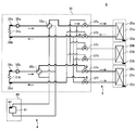
- the control device 50 is composed of, for example, a microcomputer, and controls the entire air conditioner 1. For example, the control device 50 determines the driving frequency of the compressor 11, the rotational speed of the blower (including ON / OFF), the first refrigerant flow switching device 12 based on detection results by various detection means such as a temperature sensor. Switching, opening of expansion devices 32a and 32b, opening and closing of switching devices 33a and 33b, switching of second refrigerant flow switching devices 34a and 34b, driving of pumps 35a and 35b, first heat medium flow switching device 36a And 36b, the switching of the second heat medium flow switching devices 37a to 37f, and the like, and each operation mode to be described later is executed.
- the control apparatus 50 may be provided in predetermined apparatuses, such as the outdoor unit 10, and may be provided for every apparatus.
- the air conditioner 1 can perform a cooling operation or a heating operation under the control of the control device 50 based on an instruction from each indoor unit 20. That is, in the air conditioner 1, all the indoor units 20 can be operated in the same mode, and can be operated in different modes for each indoor unit 20.
- the operation mode when all the indoor units 20 perform the cooling operation is referred to as “all cooling operation mode”
- the operation mode when the heating operation is performed is referred to as “all heating operation mode”.
- the operation mode when the cooling operation is the main is referred to as “cooling main operation mode”
- the operation mode when the heating operation is the main is the “heating main operation mode”. Called.
- FIG. 4 is a schematic diagram for explaining the refrigerant flow path in the cooling only operation mode in the refrigerant circulation circuit 5 of FIG. 2.
- a flow path indicated by a bold line is a refrigerant flow path in the cooling only operation mode, and the flow direction of the refrigerant in the refrigerant flow path is indicated by an arrow.
- the first refrigerant flow switching device 12 and the second refrigerant flow switching devices 34a and 34b are switched as shown in FIG. Further, the opening / closing device 33a is opened, and the opening / closing device 33b is closed.
- the low-temperature and low-pressure refrigerant is compressed by the compressor 11 and discharged as a high-temperature and high-pressure gas refrigerant.
- the high-temperature and high-pressure gas refrigerant discharged from the compressor 11 flows into the heat source side heat exchanger 13 via the first refrigerant flow switching device 12.
- the high-temperature and high-pressure gas refrigerant that has flowed into the heat source side heat exchanger 13 condenses while exchanging heat with the outdoor air and dissipates heat, and becomes a supercooled high-pressure liquid refrigerant that flows out of the heat source side heat exchanger 13.
- the high-pressure liquid refrigerant that has flowed out of the heat source side heat exchanger 13 flows out of the outdoor unit 10 through the check valve 14 d and flows into the intermediate heat exchanger 30.
- the high-pressure liquid refrigerant that has flowed into the intermediate heat exchanger 30 flows into the expansion devices 32a and 32b through the switching device 33a.
- the high-pressure liquid refrigerant that has flowed into the expansion device 32a is decompressed and expanded to become a low-temperature and low-pressure gas-liquid two-phase refrigerant, and flows into the first heat exchanger related to heat medium 31a.
- the low-temperature and low-pressure gas-liquid two-phase refrigerant that has flowed into the first heat exchanger related to heat medium 31a exchanges heat with the heat medium to absorb heat and evaporate, thereby cooling the heat medium and becoming a low-temperature and low-pressure gas refrigerant. It flows out of the first heat exchanger related to heat medium 31a.
- the low-temperature and low-pressure gas refrigerant that has flowed out of the first heat exchanger related to heat medium 31 a flows out of the intermediate heat exchanger 30 via the second refrigerant flow switching device 34 a and flows into the outdoor unit 10.
- the high-pressure liquid refrigerant flowing into the expansion device 32b is decompressed and expanded to become a low-temperature and low-pressure gas-liquid two-phase refrigerant, and flows into the first heat exchanger related to heat medium 31b.
- the low-temperature and low-pressure gas-liquid two-phase refrigerant flowing into the first heat exchanger related to heat medium 31b exchanges heat with the heat medium to absorb heat and evaporate, thereby cooling the heat medium and becoming a low-temperature and low-pressure gas refrigerant. It flows out of the first heat exchanger related to heat medium 31b.
- the low-temperature and low-pressure gas refrigerant that has flowed out of the first heat exchanger related to heat medium 31b flows out of the intermediate heat exchanger 30 via the second refrigerant flow switching device 34b and flows into the outdoor unit 10.
- the low-temperature and low-pressure gas refrigerant that has flowed into the outdoor unit 10 is sucked into the compressor 11 through the check valve 14a and the first refrigerant flow switching device 12, and the above-described circulation is repeated.
- FIG. 5 is a schematic diagram for explaining a refrigerant flow path in the heating only operation mode in the refrigerant circulation circuit 5 of FIG. 2.
- a flow path indicated by a thick line is a refrigerant flow path in the heating only operation mode, and the flow direction of the refrigerant in the refrigerant flow path is indicated by an arrow.
- the first refrigerant flow switching device 12 and the second refrigerant flow switching devices 34a and 34b are switched as shown in FIG.
- the opening / closing device 33a is closed and the opening / closing device 33b is opened.
- the low-temperature and low-pressure refrigerant is compressed by the compressor 11 and discharged as a high-temperature and high-pressure gas refrigerant.
- the high-temperature and high-pressure gas refrigerant discharged from the compressor 11 flows out of the outdoor unit 10 via the first refrigerant flow switching device 12 and the check valve 14c provided in the second connection pipe 2b, It flows into the heat exchanger 30.
- the high-temperature and high-pressure gas refrigerant that has flowed into the intermediate heat exchanger 30 flows into the first heat exchanger related to heat medium 31a and 31b via the second refrigerant flow switching devices 34a and 34b.
- the high-temperature and high-pressure gas refrigerant that has flowed into the first heat exchanger related to heat medium 31a exchanges heat with the heat medium and condenses while dissipating heat, thereby heating the heat medium to become a supercooled high-pressure liquid refrigerant. And flows out of the first heat exchanger related to heat medium 31a.
- the high-pressure liquid refrigerant that has flowed out of the first heat exchanger related to heat medium 31a is decompressed and expanded by the expansion device 32a, becomes a low-temperature and low-pressure gas-liquid two-phase refrigerant, and flows out of the expansion device 32a.
- the low-temperature and low-pressure gas-liquid two-phase refrigerant that has flowed out of the expansion device 32a flows out of the intermediate heat exchanger 30 through the switching device 33b and flows into the outdoor unit 10.
- the high-temperature and high-pressure gas refrigerant flowing into the first heat exchanger related to heat medium 31b exchanges heat with the heat medium and condenses while dissipating heat, thereby heating the heat medium, and in a supercooled high-pressure liquid refrigerant And flows out of the first heat exchanger related to heat medium 31b.
- the high-pressure liquid refrigerant that has flowed out of the first heat exchanger related to heat medium 31b is decompressed and expanded by the expansion device 32b, becomes a low-temperature and low-pressure gas-liquid two-phase refrigerant, and flows out of the expansion device 32b.
- the low-temperature and low-pressure gas-liquid two-phase refrigerant that has flowed out of the expansion device 32b flows out of the intermediate heat exchanger 30 through the switching device 33b and flows into the outdoor unit 10.
- the low-temperature and low-pressure gas-liquid two-phase refrigerant that has flowed into the outdoor unit 10 flows into the heat source side heat exchanger 13 through the check valve 14b provided in the first connection pipe 2a.
- the low-temperature and low-pressure gas-liquid two-phase refrigerant flowing into the heat source side heat exchanger 13 exchanges heat with outdoor air, absorbs heat and evaporates, and becomes a low temperature and low pressure gas refrigerant and flows out of the heat source side heat exchanger 13.
- the low-temperature and low-pressure gas refrigerant that has flowed out of the heat source side heat exchanger 13 is sucked into the compressor 11 through the first refrigerant flow switching device 12, and the above-described circulation is repeated thereafter.
- FIG. 6 is a schematic diagram for explaining a refrigerant flow path in the cooling main operation mode in the refrigerant circulation circuit 5 of FIG. 2.
- a flow path indicated by a thick line is a refrigerant flow path in the cooling main operation mode, and the flow direction of the refrigerant in the refrigerant flow path is indicated by an arrow.
- the first refrigerant flow switching device 12 and the second refrigerant flow switching devices 34a and 34b are switched as shown in FIG. Further, the opening / closing devices 33a and 33b are closed.
- the low-temperature and low-pressure refrigerant is compressed by the compressor 11 and discharged as a high-temperature and high-pressure gas refrigerant.
- the high-temperature and high-pressure gas refrigerant discharged from the compressor 11 flows into the heat source side heat exchanger 13 via the first refrigerant flow switching device 12.
- the high-temperature and high-pressure gas refrigerant that has flowed into the heat source side heat exchanger 13 condenses while exchanging heat with outdoor air and dissipates heat, and becomes a gas-liquid two-phase refrigerant and flows out of the heat source side heat exchanger 13.
- the gas-liquid two-phase refrigerant that has flowed out of the heat source side heat exchanger 13 flows out of the outdoor unit 10 through the check valve 14 d and flows into the intermediate heat exchanger 30.
- the gas-liquid two-phase refrigerant that has flowed into the intermediate heat exchanger 30 flows into the first heat exchanger related to heat medium 31a via the second refrigerant flow switching device 34a.
- the gas-liquid two-phase refrigerant that has flowed into the first heat exchanger related to heat medium 31a exchanges heat with the heat medium and condenses while dissipating heat, thereby heating the heat medium and becoming liquid refrigerant. It flows out of the intermediate heat exchanger 31a.
- the liquid refrigerant flowing out of the first heat exchanger related to heat medium 31a is decompressed and expanded by the expansion device 32a to become a low-temperature and low-pressure gas-liquid two-phase refrigerant and flows out of the expansion device 32a.
- the low-temperature and low-pressure gas-liquid two-phase refrigerant that has flowed out of the expansion device 32a flows into the first heat exchanger related to heat medium 31b through the expansion device 32b.
- the low-temperature and low-pressure gas-liquid two-phase refrigerant that has flowed into the first heat exchanger related to heat medium 31b exchanges heat with the heat medium to absorb heat and evaporate, thereby cooling the heat medium and becoming a low-pressure gas refrigerant. 1 flows out of the heat exchanger related to heat medium 31b.
- the low-pressure gas refrigerant that has flowed out of the first heat exchanger related to heat medium 31b flows into the outdoor unit 10 via the second refrigerant flow switching device 34b.
- the low-pressure gas refrigerant that has flowed into the outdoor unit 10 is sucked into the compressor 11 through the check valve 14a and the first refrigerant flow switching device 12, and the above-described circulation is repeated.
- the heat medium is heated by the first first heat exchanger related to heat medium 31a and the heat medium is cooled by the other first heat exchanger related to heat medium 31b.
- the second refrigerant flow switching devices 34a and 34b are switched, the heat medium is cooled by one first heat exchanger related to heat medium 31a, and the heat medium is transferred by the other first heat exchanger related to heat medium 31b. May be heated.
- FIG. 7 is a schematic diagram for explaining the refrigerant flow path in the heating main operation mode in the refrigerant circulation circuit 5 of FIG. 2.
- a flow path indicated by a thick line is a refrigerant flow path in the heating main operation mode, and the flow direction of the refrigerant in the refrigerant flow path is indicated by an arrow.
- the first refrigerant flow switching device 12 and the second refrigerant flow switching devices 34a and 34b are switched as shown in FIG. Further, the opening / closing devices 33a and 33b are closed.
- the low-temperature and low-pressure refrigerant is compressed by the compressor 11 and discharged as a high-temperature and high-pressure gas refrigerant.
- the high-temperature and high-pressure gas refrigerant discharged from the compressor 11 flows out of the outdoor unit 10 via the first refrigerant flow switching device 12 and the check valve 14 c and flows into the intermediate heat exchanger 30.
- the high-temperature and high-pressure gas refrigerant that has flowed into the intermediate heat exchanger 30 flows into the first heat exchanger related to heat medium 31b via the second refrigerant flow switching device 34b.
- the high-temperature and high-pressure gas refrigerant that has flowed into the first heat exchanger related to heat medium 31b exchanges heat with the heat medium and condenses while dissipating heat, thereby heating the heat medium and becoming a liquid refrigerant. It flows out of the intermediate heat exchanger 31b.
- the liquid refrigerant flowing out of the first heat exchanger related to heat medium 31b is decompressed and expanded by the expansion device 32b to become a low-temperature and low-pressure gas-liquid two-phase refrigerant, and flows out of the expansion device 32b.
- the low-temperature and low-pressure gas-liquid two-phase refrigerant that has flowed out of the expansion device 32b flows into the first heat exchanger related to heat medium 31a through the expansion device 32a.
- the low-temperature low-pressure gas-liquid two-phase refrigerant that has flowed into the first heat exchanger related to heat medium 31a cools the heat medium by exchanging heat with the heat medium to absorb heat and evaporate, and heat exchange between the first heat medium Out of the vessel 31a.
- the refrigerant that has flowed out of the first heat exchanger related to heat medium 31a flows into the outdoor unit 10 via the second refrigerant flow switching device 34a.
- the refrigerant that has flowed into the outdoor unit 10 flows into the heat source side heat exchanger 13 through the check valve 14b.
- the refrigerant flowing into the heat source side heat exchanger 13 exchanges heat with outdoor air, absorbs heat and evaporates, and becomes a low-temperature and low-pressure gas refrigerant and flows out of the heat source side heat exchanger 13.
- the low-temperature and low-pressure gas refrigerant that has flowed out of the heat source side heat exchanger 13 is sucked into the compressor 11 through the first refrigerant flow switching device 12, and the above-described circulation is repeated thereafter.
- the heat medium is cooled by the first first heat exchanger related to heat medium 31a, and the heat medium is heated by the other first heat exchanger related to heat medium 31b.
- the second refrigerant flow switching devices 34a and 34b are switched, the heat medium is heated by one first heat exchanger related to heat medium 31a, and the heat medium is heated by the other first heat exchanger related to heat medium 31b. May be cooled.
- the air conditioner 1 can be operated according to the use state of the heat storage tank 40 under the control of the control device 50.
- FIG. 8 is a schematic diagram for explaining a heat medium flow path when the heat storage tank 40 is not used in the heat medium circulation circuit 6 of FIG. 3.
- the flow path indicated by a thick line is a heat medium flow path when the heat storage tank 40 is not used, and the flow direction of the heat medium in the heat medium flow path is indicated by an arrow.
- the flow path of the heat medium flowing between the first heat exchanger related to heat medium 31a and the use side heat exchanger 21a and the heat exchange between the first heat medium. Only the flow path of the heat medium flowing between the heat exchanger 31b and the use side heat exchanger 21c is shown and described.
- the flow path of the heat medium flowing through the first heat exchanger related to heat medium 31a includes a flow path flowing through the use side heat exchangers 21b and 21c.
- the flow path of the heat medium flowing through the first heat exchanger related to heat medium 31b includes a flow path flowing through the use side heat exchangers 21a and 21b.
- the first heat medium flow switching devices 36a and 36b are switched as shown in FIG. Then, the heat medium cooled or heated by the first heat exchanger related to heat medium 31a passes through the pump 35a, the first heat medium flow switching device 36a, and the second heat medium flow switching device 37a. It flows out of the exchanger 30.
- the heat medium that has flowed out of the intermediate heat exchanger 30 flows into the indoor unit 20a through the heat medium pipe 3, and flows into the use side heat exchanger 21a.
- the heat medium that has flowed into the use side heat exchanger 21a exchanges heat with the room air, absorbs or dissipates heat, cools or heats the room air, and flows out of the use side heat exchanger 21a.
- the heat medium flowing out from the use side heat exchanger 21 a flows out from the indoor unit 20 a and flows into the intermediate heat exchanger 30 through the heat medium pipe 3.
- the heat medium flowing into the intermediate heat exchanger 30 flows into the first heat exchanger related to heat medium 31a via the second heat medium flow switching device 37b, and the above-described circulation is repeated.
- the heat medium cooled or heated by the first heat exchanger related to heat medium 31b passes through the pump 35b, the first heat medium flow switching device 36b, and the second heat medium flow switching device 37e. It flows out of the heat exchanger 30.
- the heat medium flowing out from the intermediate heat exchanger 30 flows into the indoor unit 20c through the heat medium pipe 3, and flows into the use side heat exchanger 21c.
- the heat medium that has flowed into the use side heat exchanger 21c exchanges heat with the indoor air, absorbs or dissipates heat, cools or heats the indoor air, and flows out of the use side heat exchanger 21c.
- the heat medium flowing out from the use side heat exchanger 21 c flows out from the indoor unit 20 c and flows into the intermediate heat exchanger 30 through the heat medium pipe 3.
- the heat medium flowing into the intermediate heat exchanger 30 flows into the first heat exchanger related to heat medium 31b via the second heat medium flow switching device 37f, and the above-described circulation is repeated thereafter.
- FIG. 9 is a schematic diagram for explaining a heat medium flow path when the heat storage tank 40 is used in the heat medium circulation circuit 6 of FIG. 3.
- a flow path indicated by a thick line is a heat medium flow path when the heat storage tank 40 is used, and a flow direction of the heat medium in the heat medium flow path is indicated by an arrow.
- the heat medium flow path of the heat medium that flows between the first heat medium heat exchanger 31a and the use side heat exchanger 21a via the heat storage tank 40 and The heat medium flow path of the heat medium that flows between the first heat exchanger related to heat medium 31b and the use side heat exchanger 21c is illustrated and described.
- the flow path of the heat medium that flows through the first heat exchanger related to heat medium 31a includes a flow path that flows through the use side heat exchangers 21b and 21c via the heat storage tank 40.
- the flow path of the heat medium that flows through the first heat exchanger related to heat medium 31b includes a flow path that flows through the use side heat exchangers 21a and 21b via the heat storage tank 40.
- the first heat medium flow switching devices 36a and 36b are switched as shown in FIG.
- the heat medium cooled or heated by the first heat exchanger related to heat medium 31a flows out from the intermediate heat exchanger 30 via the pump 35a and the first heat medium flow switching device 36a.
- the heat medium flowing out from the intermediate heat exchanger 30 flows into the heat storage tank 40 via the heat medium pipe 4 and flows into the heat storage tank 41.
- the heat medium stored in the heat storage tank 41 in the same amount as the inflowed heat medium flows out and flows out from the heat storage tank 40.
- the heat medium that has flowed out of the heat storage tank 40 flows into the intermediate heat exchanger 30 through the heat medium pipe 4.
- the heat medium flowing into the intermediate heat exchanger 30 flows out of the intermediate heat exchanger 30 via the first heat medium flow switching device 36a and the second heat medium flow switching device 37a.
- the heat medium that has flowed out of the intermediate heat exchanger 30 flows into the indoor unit 20a through the heat medium pipe 3, and flows into the use side heat exchanger 21a.
- the heat medium that has flowed into the use side heat exchanger 21a exchanges heat with the room air, absorbs or dissipates heat, cools or heats the room air, and flows out of the use side heat exchanger 21a.
- the heat medium flowing out from the use side heat exchanger 21 a flows out from the indoor unit 20 a and flows into the intermediate heat exchanger 30 through the heat medium pipe 3.
- the heat medium flowing into the intermediate heat exchanger 30 flows into the first heat exchanger related to heat medium 31a via the second heat medium flow switching device 37b, and the above-described circulation is repeated.
- the heat medium cooled or heated by the first heat exchanger related to heat medium 31b flows out from the intermediate heat exchanger 30 via the pump 35b and the first heat medium flow switching device 36b.
- the heat medium flowing out from the intermediate heat exchanger 30 flows into the heat storage tank 40 via the heat medium pipe 4 and flows into the heat storage tank 41.
- the heat medium stored in the heat storage tank 41 in the same amount as the inflowed heat medium flows out and flows out from the heat storage tank 40.
- the heat medium that has flowed out of the heat storage tank 40 flows into the intermediate heat exchanger 30 through the heat medium pipe 4.
- the heat medium flowing into the intermediate heat exchanger 30 flows out from the intermediate heat exchanger 30 via the first heat medium flow switching device 36b and the second heat medium flow switching device 37e.
- the heat medium flowing out from the intermediate heat exchanger 30 flows into the indoor unit 20c through the heat medium pipe 3, and flows into the use side heat exchanger 21c.
- the heat medium that has flowed into the use side heat exchanger 21c exchanges heat with the indoor air, absorbs or dissipates heat, cools or heats the indoor air, and flows out of the use side heat exchanger 21c.
- the heat medium flowing out from the use side heat exchanger 21 c flows out from the indoor unit 20 c and flows into the intermediate heat exchanger 30 through the heat medium pipe 3.
- the heat medium flowing into the intermediate heat exchanger 30 flows into the first heat exchanger related to heat medium 31b via the second heat medium flow switching device 37f, and the above-described circulation is repeated thereafter.
- the heat storage tank 40 is not always included in the heat medium circulation circuit 6, and it is determined whether to use the heat storage tank 40 according to preset conditions. The Then, the heat storage tank 40 is connected to the heat medium circulation circuit 6 by switching the first heat medium flow switching devices 36a and 36b according to the determination result.
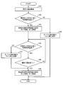
- FIG. 10 is a flowchart illustrating an example of a flow of processing for determining whether or not the heat storage tank 40 can be used during the cooling operation in the heat medium circulation circuit 6 of FIG. 3.
- a path through which the heat medium circulates by the pump 35a will be described as an example.
- the “cooling operation” in the following description refers to an operation in which the heat medium is cooled by the first heat exchanger related to heat medium 31a such as a full cooling operation and a cooling main operation.
- step S1 the control device 50 switches the first heat medium flow switching device 36a and the second heat medium flow switching devices 37a to 37f and drives the pump 35a to start the cooling operation.
- step S2 the control device 50 compares the outlet water temperature of the first heat exchanger related to heat medium 31a based on the temperature information supplied from the heat medium temperature sensor 38a with the target water temperature.
- the target water temperature indicates a temperature calculated based on the indoor temperature requested from the indoor unit 20. Specifically, for example, the temperature of the heat medium necessary for setting the temperature of the room air to the room temperature requested from the indoor unit 20 is shown.
- the outlet water temperature of the first heat exchanger related to heat medium 31a and the target water temperature are compared with the temperature at which the room air is requested by the heat medium flowing out from the first heat exchanger related to heat medium 31a. This is to determine whether or not cooling can be performed.
- step S3 the control device 50 stores heat based on the outlet water temperature of the first heat exchanger related to heat medium 31a based on the temperature information supplied from the heat medium temperature sensor 38a and the temperature information supplied from the tank temperature sensor 42.
- the water temperature of the heat medium in the tank 41 is compared.
- the reason for comparing the outlet water temperature of the first heat exchanger related to heat medium 31a with the water temperature of the heat medium in the heat storage tank 41 is to determine whether or not the heat storage tank 40 can be used.
- step S3 when it is determined that the outlet water temperature of the first heat exchanger related to heat medium 31a is higher than the water temperature of the heat medium in the heat storage tank 41 (step S3; YES), the process proceeds to step S4. .
- the control device 50 controls the first heat medium flow switching device 36a to connect the left and lower flow paths shown in the drawing of FIG. 3 and connect the right and upper flow paths. .
- the heat medium in the heat storage tank 41 flows into the heat medium circuit 6.
- step S5 the control device 50 compares the inlet water temperature of the first heat exchanger related to heat medium 31a based on the temperature information supplied from the heat medium temperature sensor 38b with the predicted water temperature.
- the predicted water temperature is calculated based on the room temperature detected by the room temperature sensor 22 of the indoor unit 20 in operation and the temperature of the heat medium in the heat storage tank 41 detected by the tank temperature sensor 42. This predicted temperature indicates the temperature of the heat medium when the heat medium flowing out of the heat storage tank 41 circulates through the heat medium circuit 6 and flows into the first heat exchanger related to heat medium 31a.
- the comparison between the inlet water temperature of the first heat exchanger related to heat medium 31a and the predicted water temperature determines whether or not the heat medium flowing out of the heat storage tank 41 has circulated through the heat medium circuit 6. Because.
- step S5 when it is determined that the inlet water temperature of the first heat exchanger related to heat medium 31a is equal to or lower than the predicted water temperature (step S5; YES), the process proceeds to step S6.
- step S5 when it is determined that the inlet water temperature of the first heat exchanger related to heat medium 31a is higher than the predicted water temperature (step S5; NO), the inlet water temperature of the first heat exchanger related to heat medium 31a is the predicted water temperature.
- step S5 is repeated until the following is obtained.
- step S6 the control device 50 controls the first heat medium flow switching device 36a to connect the left and upper flow paths shown in the drawing of FIG. 3, and to connect the right and lower flow paths. Connect. As a result, the heat storage tank 41 is disconnected from the heat medium circulation circuit 6, and a series of processing ends.
- step S2 when it is determined in step S2 that the outlet water temperature of the first heat exchanger related to heat medium 31a is equal to or lower than the target water temperature (step S2; NO), a series of processing ends. Further, when it is determined in step S3 that the outlet water temperature of the first heat exchanger related to heat medium 31a is equal to or lower than the water temperature of the heat medium in the heat storage tank 41 (step S3; NO), the series of processes is completed. To do.
- FIG. 11 is a flowchart illustrating an example of a process flow for determining whether or not the heat storage tank 40 can be used during heating operation in the heat medium circulation circuit 6 of FIG. 3.
- a path through which the heat medium circulates by the pump 35a will be described as an example.
- the “heating operation” in the following description refers to an operation in which the heat medium is heated by the first heat exchanger related to heat medium 31a such as a full heating operation and a heating main operation.
- step S11 the control device 50 switches the first heat medium flow switching device 36a and the second heat medium flow switching devices 37a to 37f and drives the pump 35a to start the heating operation.
- step S12 the control device 50 compares the outlet water temperature of the first heat exchanger related to heat medium 31a based on the temperature information supplied from the heat medium temperature sensor 38a with the target water temperature. As a result of comparison, when the outlet water temperature of the first heat exchanger related to heat medium 31a is lower than the target water temperature (step S12; YES), the heat medium flowing out from the first heat exchanger related to heat medium 31a It is determined that the air can be heated to the required temperature, and the process proceeds to step S13.
- step S13 the controller 50 stores heat based on the outlet water temperature of the first heat exchanger related to heat medium 31a based on the temperature information supplied from the heat medium temperature sensor 38a and the temperature information supplied from the tank temperature sensor 42.
- the water temperature of the heat medium in the tank 41 is compared. As a result of the comparison, when the outlet water temperature of the first heat exchanger related to heat medium 31a is lower than the water temperature of the heat medium in the heat storage tank 41 (step S13; YES), it is determined that the heat storage tank 40 is used, and processing is performed. Goes to step S14.
- step S14 the control device 50 controls the first heat medium flow switching device 36a to connect the left and lower flow paths shown in the drawing of FIG. 3 and connect the right and upper flow paths. .
- the heat medium in the heat storage tank 41 flows into the heat medium circuit 6.
- step S15 the control device 50 compares the inlet water temperature of the first heat exchanger related to heat medium 31a based on the temperature information supplied from the heat medium temperature sensor 38b with the predicted water temperature. As a result of the comparison, when the inlet water temperature of the first heat exchanger related to heat medium 31a is equal to or higher than the predicted water temperature (step S15; YES), the heat medium flowing out of the heat storage tank 41 circulates in the heat medium circulation circuit 6. Then, it is determined that it has flowed into the first heat exchanger related to heat medium 31a, and the process proceeds to step S16.
- step S15 when it is determined that the inlet water temperature of the first heat exchanger related to heat medium 31a is lower than the predicted water temperature (step S15; NO), the inlet water temperature of the first heat exchanger related to heat medium 31a is the predicted water temperature. Until this is the case, the process of step S15 is repeated.
- step S16 the control device 50 controls the first heat medium flow switching device 36a to connect the left and upper flow paths shown in the drawing of FIG. 3, and to connect the right and lower flow paths. Connect. As a result, the heat storage tank 41 is disconnected from the heat medium circulation circuit 6, and a series of processing ends.
- step S12 when it is determined in step S12 that the outlet water temperature of the first heat exchanger related to heat medium 31a is equal to or higher than the target water temperature (step S12; NO), a series of processing ends. Further, in step S13, when it is determined that the outlet water temperature of the first heat exchanger related to heat medium 31a is equal to or higher than the water temperature of the heat medium in the heat storage tank 41 (step S13; NO), the series of processes is completed. To do.
- step S11 to step S16 the temperature of the room air is quickly brought to the required temperature during the heating operation as compared with the case where the heat medium in the heat storage tank 41 is not used. You can get closer.
- the process for the path through which the heat medium circulates by the pump 35a has been described.
- FIG. 12 is a flowchart illustrating an example of a flow of processing for determining whether or not the heat storage tank 40 can be used at the end of the cooling operation in the heat medium circulation circuit 6 of FIG. 3.
- a path through which the heat medium circulates by the pump 35a will be described as an example.
- step S21 the control device 50 stops the cooling operation while maintaining the states of the first heat medium flow switching device 36a and the second heat medium flow switching devices 37a to 37f during the cooling operation. .
- step S22 the control device 50 detects the outlet water temperature of the first heat exchanger related to heat medium 31a based on the temperature information supplied from the heat medium temperature sensor 38a and the temperature information supplied from the tank temperature sensor 42.
- the water temperature of the heat medium in the heat storage tank 41 based on the above is compared.
- the comparison between the outlet water temperature of the first heat exchanger related to heat medium 31a and the water temperature of the heat medium in the heat storage tank 41 can recover the cold heat remaining in the heat medium circuit 6 to the heat storage tank 41. This is to determine whether or not.
- step S22 when it is determined that the outlet water temperature of the first heat exchanger related to heat medium 31a is lower than the water temperature of the heat medium in the heat storage tank 41 (step S22; YES), the process proceeds to step S23.
- step S23 the control device 50 controls the first heat medium flow switching device 36a to connect the left and lower flow paths shown in the drawing of FIG. 3 and to connect the right and upper flow paths. .
- the heat medium in the heat medium circulation circuit 6 having a temperature lower than that of the heat medium in the heat storage tank 41 flows into the heat storage tank 41.
- step S24 the control device 50 detects the outlet water temperature of the first heat exchanger related to heat medium 31a based on the temperature information supplied from the heat medium temperature sensor 38a and the temperature information supplied from the tank temperature sensor 42.
- the water temperature of the heat medium in the heat storage tank 41 based on the above is compared.
- the reason for comparing the outlet water temperature of the first heat exchanger related to heat medium 31a with the water temperature of the heat medium in the heat storage tank 41 is that the cold energy remaining in the heat medium circulation circuit 6 can be recovered in the heat storage tank 41. This is to determine whether or not.
- step S24 when it is determined that the outlet water temperature of the first heat exchanger related to heat medium 31a is equal to or higher than the water temperature of the heat medium in the heat storage tank 41 (step S24; YES), the process proceeds to step S25. .
- step S24 when it is determined that the outlet water temperature of the first heat exchanger related to heat medium 31a is lower than the water temperature of the heat medium in the heat storage tank 41 (step S24; NO), the first heat exchanger related to heat medium The process of step S24 is repeated until the outlet water temperature of 31a becomes equal to or higher than the water temperature of the heat medium in the heat storage tank 41.
- step S24 a margin may be given to the temperature used for the determination.
- step S25 the control device 50 controls the first heat medium flow switching device 36a to connect the left and upper flow paths shown in the drawing of FIG. 3, and to connect the right and lower flow paths. Connect. As a result, the heat storage tank 41 is disconnected from the heat medium circulation circuit 6.
- step S22 determines whether the outlet water temperature of the first heat exchanger related to heat medium 31a is equal to or higher than the water temperature of the heat medium in the heat storage tank 41 (step S22; NO). If it is determined in step S22 that the outlet water temperature of the first heat exchanger related to heat medium 31a is equal to or higher than the water temperature of the heat medium in the heat storage tank 41 (step S22; NO), the process proceeds to step S26. Transition.
- step S26 the control device 50 stops driving the pump 35a. As a result, a series of processing ends.
- step S21 to step S26 the cold energy in the heat medium circulation circuit 6 remaining when the cooling operation is stopped can be recovered in the heat storage tank 41.
- the process for the path through which the heat medium circulates by the pump 35a has been described, but the process for the path through which the heat medium circulates by the pump 35b is the same.
- FIG. 13 is a flowchart illustrating an example of a flow of processing for determining whether or not the heat storage tank 40 can be used at the end of the heating operation in the heat medium circulation circuit 6 of FIG. 3.
- a path through which the heat medium circulates by the pump 35a will be described as an example.
- step S31 the control device 50 stops the heating operation while maintaining the states of the first heat medium flow switching device 36a and the second heat medium flow switching devices 37a to 37f during the heating operation. .
- step S32 the control device 50 detects the outlet water temperature of the first heat exchanger related to heat medium 31a based on the temperature information supplied from the heat medium temperature sensor 38a, and the temperature information supplied from the tank temperature sensor 42.
- the water temperature of the heat medium in the heat storage tank 41 based on the above is compared.
- the comparison between the outlet water temperature of the first heat exchanger related to heat medium 31a and the water temperature of the heat medium in the heat storage tank 41 can recover the heat remaining in the heat medium circuit 6 in the heat storage tank 41. This is to determine whether or not.
- step S32 when it is determined that the outlet water temperature of the first heat exchanger related to heat medium 31a is higher than the water temperature of the heat medium in the heat storage tank 41 (step S32; YES), the process proceeds to step S33.
- the control device 50 controls the first heat medium flow switching device 36a to connect the left and lower flow paths shown in the drawing of FIG. 3 and connect the right and upper flow paths. .
- the heat medium in the heat medium circulation circuit 6 having a higher temperature than the heat medium in the heat storage tank 41 flows into the heat storage tank 41.
- step S34 the control device 50 detects the outlet water temperature of the first heat exchanger related to heat medium 31a based on the temperature information supplied from the heat medium temperature sensor 38a and the temperature information supplied from the tank temperature sensor 42.
- the water temperature of the heat medium in the heat storage tank 41 based on the above is compared.
- the outlet water temperature of the first heat exchanger related to heat medium 31a is compared with the water temperature of the heat medium in the heat storage tank 41 because the heat remaining in the heat medium circuit 6 can be recovered in the heat storage tank 41. This is to determine whether or not.
- step S34 when it is determined that the outlet water temperature of the first heat exchanger related to heat medium 31a is equal to or lower than the water temperature of the heat medium in the heat storage tank 41 (step S34; YES), the process proceeds to step S35. .
- step S34 if it is determined that the outlet water temperature of the first heat exchanger related to heat medium 31a is higher than the water temperature of the heat medium in the heat storage tank 41 (step S34; NO), the first heat exchanger related to heat medium The process of step S34 is repeated until the outlet water temperature of 31a becomes equal to or lower than the water temperature of the heat medium in the heat storage tank 41.
- step S34 a margin may be given to the temperature used for determination.
- step S35 the control device 50 controls the first heat medium flow switching device 36a to connect the left and upper flow paths shown in the drawing of FIG. 3, and to connect the right and lower flow paths. Connect. As a result, the heat storage tank 41 is disconnected from the heat medium circulation circuit 6.
- step S32 determines whether the outlet water temperature of the first heat exchanger related to heat medium 31a is equal to or lower than the water temperature of the heat medium in the heat storage tank 41 (step S32; NO). If it is determined in step S32 that the outlet water temperature of the first heat exchanger related to heat medium 31a is equal to or lower than the water temperature of the heat medium in the heat storage tank 41 (step S32; NO), the process proceeds to step S36. Transition.
- step S36 the control device 50 stops driving the pump 35a. As a result, a series of processing ends.
- the heat in the heat medium circulation circuit 6 remaining when the heating operation is stopped can be recovered in the heat storage tank 41 by performing the above-described processing of Step S31 to Step S36.
- the process for the path through which the heat medium circulates by the pump 35a has been described, but the process for the path through which the heat medium circulates by the pump 35b is the same.
- FIG. 14 is a flowchart illustrating an example of a process flow for determining whether or not the heat storage tank 40 can be used during the defrosting operation in the heat medium circulation circuit 6 of FIG. 3.
- all the indoor units 20a to 20c start the defrosting operation during the heating operation.
- a path through which the heat medium circulates by the pump 35a will be described as an example.
- step S42 the control device 50 compares the water temperature of the heat medium in the heat storage tank 41 based on the temperature information supplied from the tank temperature sensor 42 with the heating application temperature.
- the heating application temperature indicates the water temperature of the heat medium calculated based on the temperature information supplied from the indoor temperature sensor 22 of the indoor unit 20 during the heating operation, and will be described in the processing during the heating operation shown in FIG. Is defined as a value lower than the target water temperature.
- the heating application temperature is a temperature at which the temperature can be increased from the current room temperature, although there is no amount of heat until the room temperature reaches the target temperature required from the indoor unit 20.
- the water temperature of the heat medium in the heat storage tank 41 is compared with the heating application temperature in order to determine whether the heating operation can be performed using the heat medium in the heat storage tank 41. is there.
- step S43 the control device 50 controls the first heat medium flow switching device 36a to connect the left and lower flow paths shown in FIG. 3 and connect the right and upper flow paths. .
- the heat medium in the heat storage tank 41 flows into the heat medium circuit 6. Therefore, the heat medium having the heat from the heat storage tank 41 can be supplied also to the path through which the heat medium circulates by the pump 35a that is not given heat for defrosting, and the heating operation is performed even during the defrost operation. Can continue.
- step S45 the control device 50 compares the water temperature of the heat medium in the heat storage tank 41 with the heating application temperature, similarly to the process of step S42. As a result of the comparison, when it is determined that the water temperature of the heat medium in the heat storage tank 41 is higher than the heating application temperature (step S45; YES), the process proceeds to step S46.
- step S46 the control device 50 determines whether or not the defrosting operation has been completed. For example, a method of requesting information indicating the current operation mode from the control device 50 to the outdoor unit 10 can be determined as to whether or not the defrosting operation has ended. For example, when the operation mode changes, the control device 50 may receive information indicating the current operation mode from the outdoor unit 10.
- step S46 If it is determined that the defrosting operation has been completed (step S46; YES), the process proceeds to step S48. On the other hand, when it is determined that the defrosting operation has not ended (step S46; NO), the process returns to step S45.
- step S48 the control device 50 controls the first heat medium flow switching device 36a to connect the left and upper flow paths shown in the drawing of FIG. 3, and to connect the right and lower flow paths. Connect. As a result, the heat storage tank 41 is disconnected from the heat medium circulation circuit 6, and a series of processing ends.
- step S42 when it is determined in step S42 that the water temperature of the heat medium in the heat storage tank 41 is equal to or lower than the heating application temperature (step S42; NO), the process proceeds to step S44.
- step S44 the control device 50 performs control to stop the fans of all the indoor units 20 as in the normal defrosting operation.
- step S45 when it is determined that the water temperature of the heat medium in the heat storage tank 41 is equal to or lower than the heating application temperature (step S45; NO), the process proceeds to step S47.
- step S47 the control device 50 performs control to stop all the fans of the indoor units 20 in the same manner as in step S44.
- control device 50 After performing the processing of step S41 to step S48 in this way, the control device 50 starts processing according to the operation mode changed from the defrosting operation such as the cooling operation or the heating operation.
- the processing for the path through which the heat medium circulates by the pump 35b is the same as in the above example.
- the temperature of the heat medium flowing in and out of the first heat exchangers 31a and 31b and the heat storage tank 41 Whether or not the heat storage tank 40 is used is determined by comparing the temperature of the heat medium. Then, when the condition is satisfied, the heat storage tank 40 is connected to the heat medium circulation circuit 6, and the heat medium in the heat storage tank 41 having more cold or warmer than the heat medium circulating in the heat medium circulation circuit 6 is used. Thereby, compared with the case where the heat medium in the heat storage tank 41 is not used, the temperature of indoor air can be rapidly brought close to the required temperature.
- the temperature of the heat medium flowing out from the first heat exchangers 31 a and 31 b is compared with the temperature of the heat medium in the heat storage tank 41.
- the heat storage tank 40 is connected to the heat medium circulation circuit 6, and the heat medium circulating in the heat medium circulation circuit 6 is stored in the heat storage tank 41.
- the cold or warm heat remaining in the heat medium circulation circuit 6 can be recovered in the heat storage tank 41.
- the temperature of the heat medium in the heat storage tank 41 is compared with the heating application temperature.
- the heat storage tank 40 is connected to the heat medium circulation circuit 6, and the heat medium in the heat storage tank 41 is circulated to the heat medium circulation circuit 6. Thereby, heating operation can be continued even during defrosting operation.
- Embodiment 2 an air conditioner according to Embodiment 2 of the present invention will be described.
- the heat medium circulating in the heat medium circuit 6 is caused to flow into the heat storage tank 41, whereby cold heat or warm heat is stored in the heat storage tank 40.
- the heat exchanger between heat media for cooling or heating the heat medium in a heat storage tank is provided in a heat storage tank. Thereby, cold heat or warm heat is stored in the heat storage tank 41.
- FIG. 15 is a schematic diagram illustrating an example of the configuration of the air-conditioning apparatus 101 according to Embodiment 2 of the present invention.
- the air conditioner 101 includes an outdoor unit 10 as a heat source unit, a plurality of indoor units 20, an intermediate heat exchanger 130, a heat storage tank 140, and a control device 50.
- the example of FIG. 15 shows a case where two indoor units 20 are provided, the present invention is not limited thereto, and for example, three or more indoor units 20 may be provided.
- the same parts as those in the first embodiment are denoted by the same reference numerals, and detailed description thereof is omitted.
- the indoor unit 20 in the air conditioner 101, the heat medium circuit 6 side of the intermediate heat exchanger 130, and the heat medium circuit 6 side of the heat storage tank 140 are the same as those in the first embodiment. Description is omitted.
- the outdoor unit 10 is connected to the refrigerant side flow path of the intermediate heat exchanger 130 by two refrigerant pipes 2 through which refrigerant flows.
- the refrigerant side flow path of the intermediate heat exchanger 130 is connected to the refrigerant side flow path of the heat storage tank 140 by the three refrigerant pipes 7.
- the refrigerant circulation circuit 5 is formed by the outdoor unit 10, the intermediate heat exchanger 130, the heat storage tank 140, and the refrigerant pipes 2 and 7.
- each of the plurality of indoor units 20 is connected to the heat medium side flow path of the intermediate heat exchanger 30 by two heat medium pipes 3 through which the heat medium flows.
- the heat medium side flow path of the heat storage tank 40 is connected to the heat medium side flow path of the intermediate heat exchanger 30 by two heat medium pipes 4 through which the heat medium flows.
- the heat medium circulation circuit 6 is formed by the plurality of indoor units 20, the intermediate heat exchanger 130, the heat storage tank 140, and the heat medium pipes 3 and 4.
- FIG. 16 is a schematic diagram illustrating an example of a circuit configuration of the refrigerant circulation circuit 5 of the air-conditioning apparatus 101 according to Embodiment 2 of the present invention.
- the refrigerant circulation circuit 5 includes the outdoor unit 10, the intermediate heat exchanger 130, the heat storage tank 140, and the refrigerant pipes 2 and 7.
- the intermediate heat exchanger 130 and the heat storage tank 140 include a portion related to the refrigerant circulation circuit 5 and a portion related to the heat medium circulation circuit 6.
- the outdoor unit 10 is the same as that of Embodiment 1 mentioned above, description is abbreviate
- the intermediate heat exchanger 130 is provided with three refrigerant pipes 7 connected to the heat storage tank 140.
- the heat storage tank 140 includes a second heat exchanger related to heat medium 141, an expansion device 142, and a third refrigerant flow switching device 143.
- the second heat exchanger related to heat medium 141 functions as a condenser or an evaporator, and exchanges heat between the refrigerant flowing through the refrigerant circulation circuit 5 and the heat medium in the heat storage tank 41 (not shown) in the heat storage tank 140. Do.
- the second heat exchanger related to heat medium 141 is provided between the expansion device 142 and the third refrigerant flow switching device 143.
- the expansion device 142 functions as an expansion valve that depressurizes and expands the refrigerant flowing in the refrigerant circulation circuit 5.
- the expansion device 142 is configured by a valve capable of controlling the opening, such as an electronic expansion valve.
- the expansion device 142 is provided upstream of the second heat exchanger related to heat medium 141 in the flow of the refrigerant when the cold energy is stored in the heat storage tank 140.
- the third refrigerant flow switching device 143 switches the direction of refrigerant flow according to the operation mode.
- coolant flow path switching apparatus 143 shown in FIG. 16 shows the state in the case of accumulating warm heat in the thermal storage tank 140.
- a four-way valve can be used as the third refrigerant flow switching device 143, but other valves may be used in combination.
- coolant flow path switching apparatus 143 is provided in the downstream of the 1st heat exchanger 31a between heat exchangers in the flow of the refrigerant
- FIG. 17 is a schematic diagram for explaining the refrigerant flow paths in the cooling circuit operation mode and the cold heat storage mode in the refrigerant circuit 5 of FIG.
- a flow path indicated by a thick line is a refrigerant flow path during the cooling only operation mode and during cold heat storage in the heat storage tank 140, and the flow direction of the refrigerant in the refrigerant flow path is indicated by an arrow.
- the first refrigerant flow switching device 12 the second refrigerant flow switching devices 34a and 34b, and the third refrigerant flow switching device 143 are switched as shown in FIG. Further, the opening / closing device 33a is opened, and the opening / closing device 33b is closed.
- the low-temperature and low-pressure refrigerant is compressed by the compressor 11 and discharged as a high-temperature and high-pressure gas refrigerant.
- the high-temperature and high-pressure gas refrigerant discharged from the compressor 11 flows into the heat source side heat exchanger 13 via the first refrigerant flow switching device 12.
- the high-temperature and high-pressure gas refrigerant that has flowed into the heat source side heat exchanger 13 condenses while exchanging heat with the outdoor air and dissipates heat, and becomes a supercooled high-pressure liquid refrigerant that flows out of the heat source side heat exchanger 13.
- the high-pressure liquid refrigerant that has flowed out of the heat source side heat exchanger 13 flows out of the outdoor unit 10 through the check valve 14d and flows into the intermediate heat exchanger 130.
- the high-pressure liquid refrigerant that has flowed into the intermediate heat exchanger 130 flows into the expansion devices 32a and 32b through the opening / closing device 33a. Further, this high-pressure liquid refrigerant flows out of the intermediate heat exchanger 130 as it is, and also flows into the heat storage tank 140 through the refrigerant pipe 7.
- the high-pressure liquid refrigerant that has flowed into the expansion device 32a is decompressed and expanded to become a low-temperature and low-pressure gas-liquid two-phase refrigerant, and flows into the first heat exchanger related to heat medium 31a.
- the low-temperature and low-pressure gas-liquid two-phase refrigerant that has flowed into the first heat exchanger related to heat medium 31a exchanges heat with the heat medium to absorb heat and evaporate, thereby cooling the heat medium and becoming a low-temperature and low-pressure gas refrigerant. It flows out of the first heat exchanger related to heat medium 31a.
- the low-temperature and low-pressure gas refrigerant that has flowed out of the first heat exchanger related to heat medium 31a flows out of the intermediate heat exchanger 130 via the second refrigerant flow switching device 34a and flows into the outdoor unit 10.
- the high-pressure liquid refrigerant flowing into the expansion device 32b is decompressed and expanded to become a low-temperature and low-pressure gas-liquid two-phase refrigerant, and flows into the first heat exchanger related to heat medium 31b.
- the low-temperature and low-pressure gas-liquid two-phase refrigerant flowing into the first heat exchanger related to heat medium 31b exchanges heat with the heat medium to absorb heat and evaporate, thereby cooling the heat medium and becoming a low-temperature and low-pressure gas refrigerant. It flows out of the first heat exchanger related to heat medium 31b.
- the low-temperature and low-pressure gas refrigerant that has flowed out of the first heat exchanger related to heat medium 31b flows out of the intermediate heat exchanger 130 via the second refrigerant flow switching device 34b and flows into the outdoor unit 10.
- the high-pressure liquid refrigerant that has flowed into the heat storage tank 140 is decompressed and expanded by the expansion device 142 to become a low-temperature and low-pressure gas-liquid two-phase refrigerant, and flows into the second heat exchanger related to heat medium 141.
- the low-temperature and low-pressure gas-liquid two-phase refrigerant flowing into the second heat exchanger related to heat medium 141 exchanges heat with the heat medium in the heat storage tank 41 to absorb heat and evaporate, thereby cooling the heat medium. It becomes a gas refrigerant and flows out of the second heat exchanger related to heat medium 141.
- the low-temperature and low-pressure gas refrigerant that has flowed out of the second heat exchanger related to heat medium 141 flows out of the heat storage tank 140 via the third refrigerant flow switching device 143, and is also connected to the intermediate heat exchanger via the refrigerant pipe 7. 130 flows.
- the low-temperature and low-pressure gas refrigerant that has flowed into the intermediate heat exchanger 130 flows out of the intermediate heat exchanger 130 and flows into the outdoor unit 10 as it is.
- the low-temperature and low-pressure gas refrigerant that has flowed into the outdoor unit 10 is sucked into the compressor 11 through the check valve 14a and the first refrigerant flow switching device 12, and the above-described circulation is repeated.
- FIG. 18 is a schematic diagram for explaining the refrigerant flow path during the cooling only operation mode and the thermal heat storage in the refrigerant circuit 5 of FIG.
- a flow path indicated by a thick line is a refrigerant flow path during the cooling only operation mode and during heat storage in the heat storage tank 140, and the flow direction of the refrigerant in the refrigerant flow path is indicated by an arrow.
- the first refrigerant flow switching device 12 the second refrigerant flow switching devices 34a and 34b, and the third refrigerant flow switching device 143 are switched as shown in FIG. Further, the opening / closing devices 33a and 33b are closed.
- the low-temperature and low-pressure refrigerant is compressed by the compressor 11 and discharged as a high-temperature and high-pressure gas refrigerant.
- the high-temperature and high-pressure gas refrigerant discharged from the compressor 11 flows into the heat source side heat exchanger 13 via the first refrigerant flow switching device 12.
- the high-temperature and high-pressure gas refrigerant that has flowed into the heat source side heat exchanger 13 condenses while exchanging heat with outdoor air and dissipates heat, and becomes a gas-liquid two-phase refrigerant and flows out of the heat source side heat exchanger 13.
- the gas-liquid two-phase refrigerant that has flowed out of the heat source side heat exchanger 13 flows out of the outdoor unit 10 through the check valve 14d and flows into the intermediate heat exchanger 130.
- the gas-liquid two-phase refrigerant that has flowed into the intermediate heat exchanger 130 flows out of the intermediate heat exchanger 130 as it is, and flows into the heat storage tank 140 through the refrigerant pipe 7.
- the gas-liquid two-phase refrigerant that has flowed into the heat storage tank 140 flows into the second heat exchanger related to heat medium 141 via the third refrigerant flow switching device 143.
- the gas-liquid two-phase refrigerant flowing into the second heat exchanger related to heat medium 141 exchanges heat with the heat medium in the heat storage tank 41 and condenses while dissipating heat, thereby heating the heat medium and becoming liquid refrigerant. It flows out of the second heat exchanger related to heat medium 141.
- the liquid refrigerant flowing out of the second heat exchanger related to heat medium 141 is decompressed and expanded by the expansion device 142 to become a low-temperature and low-pressure gas-liquid two-phase refrigerant, and flows out of the expansion device 142.
- the low-temperature and low-pressure gas-liquid two-phase refrigerant that has flowed out of the expansion device 142 flows out of the heat storage tank 140 and flows into the intermediate heat exchanger 130 through the refrigerant pipe 7.
- the low-temperature and low-pressure gas-liquid two-phase refrigerant that has flowed into the intermediate heat exchanger 130 flows into the first heat exchangers 31a and 31b through the expansion devices 32a and 32b.
- the low-temperature and low-pressure gas-liquid two-phase refrigerant that has flowed into the first heat exchanger related to heat medium 31a exchanges heat with the heat medium to absorb heat and evaporate, thereby cooling the heat medium and becoming a low-pressure gas refrigerant. 1 from the heat exchanger related to heat medium 31a.
- the low-pressure gas refrigerant that has flowed out of the first heat exchanger related to heat medium 31 a flows out of the intermediate heat exchanger 130 via the second refrigerant flow switching device 34 a and flows into the outdoor unit 10.
- the low-temperature and low-pressure gas-liquid two-phase refrigerant flowing into the first heat exchanger related to heat medium 31b exchanges heat with the heat medium to absorb heat and evaporate, thereby cooling the heat medium and becoming a low-pressure gas refrigerant. And flows out from the first heat exchanger related to heat medium 31b.
- the low-pressure gas refrigerant flowing out from the first heat exchanger related to heat medium 31b flows out from the intermediate heat exchanger 130 via the second refrigerant flow switching device 34b and flows into the outdoor unit 10.
- the low-pressure gas refrigerant that has flowed into the outdoor unit 10 is sucked into the compressor 11 through the check valve 14a and the first refrigerant flow switching device 12, and the above-described circulation is repeated.
- FIG. 19 is a schematic diagram for explaining the refrigerant flow path in the heating circuit operation mode and in the cold heat storage in the refrigerant circuit 5 of FIG.
- a flow path indicated by a bold line is a refrigerant flow path during the heating only operation mode and during cold heat storage to the heat storage tank 140, and the flow direction of the refrigerant in the refrigerant flow path is indicated by an arrow.
- the first refrigerant flow switching device 12 the second refrigerant flow switching devices 34a and 34b, and the third refrigerant flow switching device 143 are switched as shown in FIG. Further, the opening / closing devices 33a and 33b are closed.
- the low-temperature and low-pressure refrigerant is compressed by the compressor 11 and discharged as a high-temperature and high-pressure gas refrigerant.
- the high-temperature and high-pressure gas refrigerant discharged from the compressor 11 flows out of the outdoor unit 10 via the first refrigerant flow switching device 12 and the check valve 14c provided in the second connection pipe 2b, It flows into the heat exchanger 130.
- the high-temperature and high-pressure gas refrigerant that has flowed into the intermediate heat exchanger 130 flows into the first heat exchanger related to heat medium 31a and 31b via the second refrigerant flow switching devices 34a and 34b.
- the high-temperature and high-pressure gas refrigerant that has flowed into the first heat exchanger related to heat medium 31a exchanges heat with the heat medium and condenses while dissipating heat, thereby heating the heat medium to become a supercooled high-pressure liquid refrigerant. And flows out of the first heat exchanger related to heat medium 31a.
- the high-pressure liquid refrigerant that has flowed out of the first heat exchanger related to heat medium 31a is decompressed and expanded by the expansion device 32a, becomes a low-temperature and low-pressure gas-liquid two-phase refrigerant, and flows out of the expansion device 32a.
- the high-temperature and high-pressure gas refrigerant flowing into the first heat exchanger related to heat medium 31b exchanges heat with the heat medium and condenses while dissipating heat, thereby heating the heat medium, and in a supercooled high-pressure liquid refrigerant And flows out of the first heat exchanger related to heat medium 31b.
- the high-pressure liquid refrigerant that has flowed out of the first heat exchanger related to heat medium 31b is decompressed and expanded by the expansion device 32b, becomes a low-temperature and low-pressure gas-liquid two-phase refrigerant, and flows out of the expansion device 32b.
- the low-temperature and low-pressure gas-liquid two-phase refrigerant that has flowed out of the expansion devices 32 a and 32 b flows out of the intermediate heat exchanger 130 and flows into the heat storage tank 140 through the refrigerant pipe 7.
- the low-temperature and low-pressure gas-liquid two-phase refrigerant flowing into the second heat exchanger related to heat medium 141 exchanges heat with the heat medium in the heat storage tank 41 to absorb heat and evaporate, thereby cooling the heat medium. It becomes a gas refrigerant and flows out of the second heat exchanger related to heat medium 141.
- the low-temperature and low-pressure gas refrigerant that has flowed out of the second heat exchanger related to heat medium 141 flows out of the heat storage tank 140 via the third refrigerant flow switching device 143, and is also connected to the intermediate heat exchanger via the refrigerant pipe 7. 130 flows.
- the low-temperature and low-pressure gas refrigerant that has flowed into the intermediate heat exchanger 130 flows out of the intermediate heat exchanger 130 and flows into the outdoor unit 10 as it is.
- the low-temperature and low-pressure gas refrigerant that has flowed into the outdoor unit 10 flows into the heat source side heat exchanger 13 through the check valve 14b provided in the first connection pipe 2a.
- the low-temperature and low-pressure gas refrigerant flowing into the heat source side heat exchanger 13 exchanges heat with outdoor air, absorbs heat and evaporates, and flows out of the heat source side heat exchanger 13.
- the low-temperature and low-pressure gas refrigerant that has flowed out of the heat source side heat exchanger 13 is sucked into the compressor 11 through the first refrigerant flow switching device 12, and the above-described circulation is repeated thereafter.
- FIG. 20 is a schematic diagram for explaining a refrigerant flow path during the heating only operation mode and the thermal heat storage in the refrigerant circulation circuit 5 of FIG. 16.
- a flow path indicated by a thick line is a refrigerant flow path during the heating only operation mode and during heat storage in the heat storage tank 140, and the flow direction of the refrigerant in the refrigerant flow path is indicated by an arrow.
- the first refrigerant flow switching device 12 the second refrigerant flow switching devices 34a and 34b, and the third refrigerant flow switching device 143 are switched as shown in FIG.
- the opening / closing device 33a is closed and the opening / closing device 33b is opened.
- the low-temperature and low-pressure refrigerant is compressed by the compressor 11 and discharged as a high-temperature and high-pressure gas refrigerant.
- the high-temperature and high-pressure gas refrigerant discharged from the compressor 11 flows out of the outdoor unit 10 via the first refrigerant flow switching device 12 and the check valve 14c provided in the second connection pipe 2b, It flows into the heat exchanger 130.
- the high-temperature and high-pressure gas refrigerant that has flowed into the intermediate heat exchanger 130 flows into the first heat exchanger related to heat medium 31a and 31b via the second refrigerant flow switching devices 34a and 34b.
- the high-temperature and high-pressure gas refrigerant flows out of the intermediate heat exchanger 130 as it is and flows into the heat storage tank 140 through the refrigerant pipe 7.
- the high-temperature and high-pressure gas refrigerant that has flowed into the first heat exchanger related to heat medium 31a exchanges heat with the heat medium and condenses while dissipating heat, thereby heating the heat medium to become a supercooled high-pressure liquid refrigerant. And flows out of the first heat exchanger related to heat medium 31a.
- the high-pressure liquid refrigerant that has flowed out of the first heat exchanger related to heat medium 31a is decompressed and expanded by the expansion device 32a, becomes a low-temperature and low-pressure gas-liquid two-phase refrigerant, and flows out of the expansion device 32a.
- the low-temperature and low-pressure gas-liquid two-phase refrigerant that has flowed out of the expansion device 32a flows out of the intermediate heat exchanger 130 through the switching device 33b and flows into the outdoor unit 10.
- the high-temperature and high-pressure gas refrigerant flowing into the first heat exchanger related to heat medium 31b exchanges heat with the heat medium and condenses while dissipating heat, thereby heating the heat medium, and in a supercooled high-pressure liquid refrigerant And flows out of the first heat exchanger related to heat medium 31b.
- the high-pressure liquid refrigerant that has flowed out of the first heat exchanger related to heat medium 31b is decompressed and expanded by the expansion device 32b, becomes a low-temperature and low-pressure gas-liquid two-phase refrigerant, and flows out of the expansion device 32b.
- the low-temperature and low-pressure gas-liquid two-phase refrigerant that has flowed out of the expansion device 32b flows out of the intermediate heat exchanger 130 through the switching device 33b and flows into the outdoor unit 10.
- the high-temperature and high-pressure gas refrigerant that has flowed into the heat storage tank 140 flows into the second heat exchanger related to heat medium 141 via the third refrigerant flow switching device 143.
- the high-temperature and high-pressure gas refrigerant flowing into the second heat exchanger related to heat medium 141 exchanges heat with the heat medium and condenses while dissipating heat, thereby heating the heat medium to become a supercooled high-pressure liquid refrigerant. And flows out of the second heat exchanger related to heat medium 141.
- the high-pressure liquid refrigerant that has flowed out of the second heat exchanger related to heat medium 141 is decompressed and expanded by the expansion device 142 to become a low-temperature and low-pressure gas-liquid two-phase refrigerant, and flows out of the expansion device 142.
- the low-temperature and low-pressure gas-liquid two-phase refrigerant that has flowed out of the expansion device 142 flows out of the heat storage tank 140 and flows into the intermediate heat exchanger 130 through the refrigerant pipe 7.
- the low-temperature and low-pressure gas-liquid two-phase refrigerant that has flowed into the intermediate heat exchanger 130 flows out of the intermediate heat exchanger 130 via the switchgear 33b and flows into the outdoor unit 10.
- the low-temperature and low-pressure gas-liquid two-phase refrigerant that has flowed into the outdoor unit 10 flows into the heat source side heat exchanger 13 through the check valve 14b provided in the first connection pipe 2a.
- the low-temperature and low-pressure gas-liquid two-phase refrigerant flowing into the heat source side heat exchanger 13 exchanges heat with outdoor air, absorbs heat and evaporates, and becomes a low temperature and low pressure gas refrigerant and flows out of the heat source side heat exchanger 13.
- the low-temperature and low-pressure gas refrigerant that has flowed out of the heat source side heat exchanger 13 is sucked into the compressor 11 through the first refrigerant flow switching device 12, and the above-described circulation is repeated thereafter.
- FIG. 21 is a schematic diagram for explaining the refrigerant flow path in the cooling main operation mode and the cold heat storage in the refrigerant circulation circuit 5 of FIG. 16.
- a flow path indicated by a thick line is a refrigerant flow path during the cooling main operation mode and during cold heat storage in the heat storage tank 140, and the flow direction of the refrigerant in the refrigerant flow path is indicated by an arrow.
- the first refrigerant flow switching device 12 the second refrigerant flow switching devices 34a and 34b, and the third refrigerant flow switching device 143 are switched as shown in FIG. Further, the opening / closing devices 33a and 33b are closed.
- the low-temperature and low-pressure refrigerant is compressed by the compressor 11 and discharged as a high-temperature and high-pressure gas refrigerant.
- the high-temperature and high-pressure gas refrigerant discharged from the compressor 11 flows into the heat source side heat exchanger 13 via the first refrigerant flow switching device 12.
- the high-temperature and high-pressure gas refrigerant that has flowed into the heat source side heat exchanger 13 condenses while exchanging heat with outdoor air and dissipates heat, and becomes a gas-liquid two-phase refrigerant and flows out of the heat source side heat exchanger 13.
- the gas-liquid two-phase refrigerant that has flowed out of the heat source side heat exchanger 13 flows out of the outdoor unit 10 through the check valve 14d and flows into the intermediate heat exchanger 130.
- the gas-liquid two-phase refrigerant that has flowed into the intermediate heat exchanger 130 flows into the first heat exchanger related to heat medium 31a via the second refrigerant flow switching device 34a.
- the gas-liquid two-phase refrigerant that has flowed into the first heat exchanger related to heat medium 31a exchanges heat with the heat medium and condenses while dissipating heat, thereby heating the heat medium and becoming liquid refrigerant. It flows out of the intermediate heat exchanger 31a.
- the liquid refrigerant flowing out of the first heat exchanger related to heat medium 31a is decompressed and expanded by the expansion device 32a to become a low-temperature and low-pressure gas-liquid two-phase refrigerant and flows out of the expansion device 32a.
- the low-temperature and low-pressure gas-liquid two-phase refrigerant that has flowed out of the expansion device 32a flows into the first heat exchanger related to heat medium 31b through the expansion device 32b.
- the low-temperature and low-pressure gas-liquid two-phase refrigerant flows out of the intermediate heat exchanger 130 and also flows into the heat storage tank 140 through the refrigerant pipe 7.
- the low-temperature and low-pressure gas-liquid two-phase refrigerant that has flowed into the first heat exchanger related to heat medium 31b exchanges heat with the heat medium to absorb heat and evaporate, thereby cooling the heat medium and becoming a low-pressure gas refrigerant. 1 flows out of the heat exchanger related to heat medium 31b.
- the low-pressure gas refrigerant flowing out from the first heat exchanger related to heat medium 31b flows out from the intermediate heat exchanger 130 via the second refrigerant flow switching device 34b and flows into the outdoor unit 10.
- the low-temperature and low-pressure gas-liquid two-phase refrigerant flowing into the second heat exchanger related to heat medium 141 exchanges heat with the heat medium in the heat storage tank 41 to absorb heat and evaporate, thereby cooling the heat medium and reducing the low-pressure gas. It becomes a refrigerant and flows out of the second heat exchanger related to heat medium 141.
- the low-pressure gas refrigerant that has flowed out of the second heat exchanger related to heat medium 141 flows out of the heat storage tank 140 via the third refrigerant flow switching device 143, and also the intermediate heat exchanger 130 via the refrigerant pipe 7. Flow into.
- the low-pressure gas refrigerant that has flowed into the intermediate heat exchanger 130 flows out of the intermediate heat exchanger 130 and flows into the outdoor unit 10 as it is.
- the low-pressure gas refrigerant that has flowed into the outdoor unit 10 is sucked into the compressor 11 through the check valve 14a and the first refrigerant flow switching device 12, and the above-described circulation is repeated.
- FIG. 22 is a schematic diagram for explaining the refrigerant flow path in the cooling main operation mode and the thermal heat storage in the refrigerant circulation circuit 5 of FIG. 16.
- a flow path indicated by a thick line is a refrigerant flow path during the cooling main operation mode and during the heat storage to the heat storage tank 140, and the flow direction of the refrigerant in the refrigerant flow path is indicated by an arrow.
- the first refrigerant flow switching device 12 the second refrigerant flow switching devices 34a and 34b, and the third refrigerant flow switching device 143 are switched as shown in FIG. Further, the opening / closing devices 33a and 33b are closed.
- the low-temperature and low-pressure refrigerant is compressed by the compressor 11 and discharged as a high-temperature and high-pressure gas refrigerant.
- the high-temperature and high-pressure gas refrigerant discharged from the compressor 11 flows into the heat source side heat exchanger 13 via the first refrigerant flow switching device 12.
- the high-temperature and high-pressure gas refrigerant that has flowed into the heat source side heat exchanger 13 condenses while exchanging heat with outdoor air and dissipates heat, and becomes a gas-liquid two-phase refrigerant and flows out of the heat source side heat exchanger 13.
- the gas-liquid two-phase refrigerant that has flowed out of the heat source side heat exchanger 13 flows out of the outdoor unit 10 through the check valve 14d and flows into the intermediate heat exchanger 130.
- the gas-liquid two-phase refrigerant that has flowed into the intermediate heat exchanger 130 flows into the first heat exchanger related to heat medium 31a via the second refrigerant flow switching device 34a.
- the gas-liquid two-phase refrigerant flows out of the intermediate heat exchanger 130 as it is and flows into the heat storage tank 140 through the refrigerant pipe 7.
- the gas-liquid two-phase refrigerant that has flowed into the first heat exchanger related to heat medium 31a exchanges heat with the heat medium and condenses while dissipating heat, thereby heating the heat medium and becoming liquid refrigerant. It flows out of the intermediate heat exchanger 31a.
- the liquid refrigerant flowing out of the first heat exchanger related to heat medium 31a is decompressed and expanded by the expansion device 32a to become a low-temperature and low-pressure gas-liquid two-phase refrigerant and flows out of the expansion device 32a.
- the gas-liquid two-phase refrigerant that has flowed into the heat storage tank 140 flows into the second heat exchanger related to heat medium 141 via the third refrigerant flow switching device 143.
- the gas-liquid two-phase refrigerant that has flowed into the second heat exchanger related to heat medium 141 exchanges heat with the heat medium and condenses while dissipating heat, thereby heating the heat medium and becoming a supercooled high-pressure liquid refrigerant. And flows out of the second heat exchanger related to heat medium 141.
- the high-pressure liquid refrigerant that has flowed out of the second heat exchanger related to heat medium 141 is decompressed and expanded by the expansion device 142 to become a low-temperature and low-pressure gas-liquid two-phase refrigerant, and flows out of the expansion device 142.
- the low-temperature and low-pressure gas-liquid two-phase refrigerant that has flowed out of the expansion device 142 flows out of the heat storage tank 140 and flows into the intermediate heat exchanger 130 through the refrigerant pipe 7.
- the low-temperature and low-pressure gas-liquid two-phase refrigerant that has flowed out of the expansion device 32a and the low-temperature and low-pressure gas-liquid two-phase refrigerant that has flowed into the intermediate heat exchanger 130 from the expansion device 142 are transferred between the first heat medium via the expansion device 32b. It flows into the heat exchanger 31b.
- the low-temperature and low-pressure gas-liquid two-phase refrigerant that has flowed into the first heat exchanger related to heat medium 31b exchanges heat with the heat medium to absorb heat and evaporate, thereby cooling the heat medium and becoming a low-pressure gas refrigerant. 1 flows out of the heat exchanger related to heat medium 31b.
- the low-pressure gas refrigerant flowing out from the first heat exchanger related to heat medium 31b flows out from the intermediate heat exchanger 130 via the second refrigerant flow switching device 34b and flows into the outdoor unit 10.
- the low-pressure gas refrigerant that has flowed into the outdoor unit 10 is sucked into the compressor 11 through the check valve 14a and the first refrigerant flow switching device 12, and the above-described circulation is repeated.
- FIG. 23 is a schematic diagram for explaining the refrigerant flow path in the heating main operation mode and in the cold heat storage in the refrigerant circulation circuit 5 of FIG. 16.
- a flow path indicated by a thick line is a refrigerant flow path at the time of the heating main operation mode and cold heat storage to the heat storage tank 140, and the flow direction of the refrigerant in the refrigerant flow path is indicated by an arrow.
- the first refrigerant flow switching device 12 the second refrigerant flow switching devices 34a and 34b, and the third refrigerant flow switching device 143 are switched as shown in FIG. Further, the opening / closing devices 33a and 33b are closed.
- the low-temperature and low-pressure refrigerant is compressed by the compressor 11 and discharged as a high-temperature and high-pressure gas refrigerant.
- the high-temperature and high-pressure gas refrigerant discharged from the compressor 11 flows out of the outdoor unit 10 via the first refrigerant flow switching device 12 and the check valve 14c provided in the second connection pipe 2b, It flows into the heat exchanger 130.
- the high-temperature and high-pressure gas refrigerant that has flowed into the intermediate heat exchanger 130 flows into the first heat exchanger related to heat medium 31b via the second refrigerant flow switching device 34b.
- the high-temperature and high-pressure gas refrigerant that has flowed into the first heat exchanger related to heat medium 31b exchanges heat with the heat medium and condenses while dissipating heat, thereby heating the heat medium to become a supercooled high-pressure liquid refrigerant. And flows out from the first heat exchanger related to heat medium 31b.
- the high-pressure liquid refrigerant that has flowed out of the first heat exchanger related to heat medium 31b is decompressed and expanded by the expansion device 32b to become a low-temperature and low-pressure gas-liquid two-phase refrigerant and flows out of the expansion device 32b.
- the low-temperature and low-pressure gas-liquid two-phase refrigerant that has flowed out of the expansion device 32b flows into the first heat exchanger related to heat medium 31a through the expansion device 32a.
- the low-temperature and low-pressure gas-liquid two-phase refrigerant flows out of the intermediate heat exchanger 130 and also flows into the heat storage tank 140 through the refrigerant pipe 7.
- the low-temperature and low-pressure gas-liquid two-phase refrigerant that has flowed into the first heat exchanger related to heat medium 31a exchanges heat with the heat medium to absorb heat and evaporate, thereby cooling the heat medium and becoming a low-pressure gas refrigerant. 1 from the heat exchanger related to heat medium 31a.
- the low-pressure gas refrigerant that has flowed out of the first heat exchanger related to heat medium 31 a flows out of the intermediate heat exchanger 130 via the second refrigerant flow switching device 34 a and flows into the outdoor unit 10.
- the low-temperature and low-pressure gas-liquid two-phase refrigerant flowing into the second heat exchanger related to heat medium 141 exchanges heat with the heat medium in the heat storage tank 41 to absorb heat and evaporate, thereby cooling the heat medium and reducing the low-pressure gas. It becomes a refrigerant and flows out of the second heat exchanger related to heat medium 141.
- the low-pressure gas refrigerant that has flowed out of the second heat exchanger related to heat medium 141 flows out of the heat storage tank 140 via the third refrigerant flow switching device 143, and also the intermediate heat exchanger 130 via the refrigerant pipe 7. Flow into.
- the low-pressure gas refrigerant that has flowed into the intermediate heat exchanger 130 flows out of the intermediate heat exchanger 130 and flows into the outdoor unit 10 as it is.
- the low-pressure gas refrigerant that has flowed into the outdoor unit 10 flows into the heat source side heat exchanger 13 through the check valve 14b provided in the first connection pipe 2a.
- the low-pressure gas refrigerant flowing into the heat source side heat exchanger 13 exchanges heat with outdoor air, absorbs heat and evaporates, and flows out of the heat source side heat exchanger 13.
- the low-pressure gas refrigerant that has flowed out of the heat source side heat exchanger 13 is sucked into the compressor 11 via the first refrigerant flow switching device 12, and the above-described circulation is repeated thereafter.
- FIG. 24 is a schematic diagram for explaining a refrigerant flow path in the heating main operation mode and in the heat storage in the refrigerant circulation circuit 5 of FIG. 16.
- the flow path indicated by the thick line is the refrigerant flow path during the heating main operation mode and during the heat storage to the heat storage tank 140, and the flow direction of the refrigerant in the refrigerant flow path is indicated by an arrow.
- the first refrigerant flow switching device 12 the second refrigerant flow switching devices 34a and 34b, and the third refrigerant flow switching device 143 are switched as shown in FIG. Further, the opening / closing devices 33a and 33b are closed.
- the low-temperature and low-pressure refrigerant is compressed by the compressor 11 and discharged as a high-temperature and high-pressure gas refrigerant.
- the high-temperature and high-pressure gas refrigerant discharged from the compressor 11 flows out of the outdoor unit 10 via the first refrigerant flow switching device 12 and the check valve 14c provided in the second connection pipe 2b, It flows into the heat exchanger 130.
- the high-temperature and high-pressure gas refrigerant that has flowed into the intermediate heat exchanger 130 flows into the first heat exchanger related to heat medium 31b via the second refrigerant flow switching device 34b.
- the high-temperature and high-pressure gas refrigerant flows out from the intermediate heat exchanger 130 and also flows into the heat storage tank 140 through the refrigerant pipe 7.
- the high-temperature and high-pressure gas refrigerant that has flowed into the first heat exchanger related to heat medium 31b exchanges heat with the heat medium and condenses while dissipating heat, thereby heating the heat medium to become a supercooled high-pressure liquid refrigerant. And flows out from the first heat exchanger related to heat medium 31b.
- the high-pressure liquid refrigerant that has flowed out of the first heat exchanger related to heat medium 31b is decompressed and expanded by the expansion device 32b, becomes a low-temperature and low-pressure gas-liquid two-phase refrigerant, and flows out of the expansion device 32b.
- the high-temperature and high-pressure gas refrigerant that has flowed into the heat storage tank 140 flows into the second heat exchanger related to heat medium 141 via the third refrigerant flow switching device 143.
- the high-temperature and high-pressure gas refrigerant flowing into the second heat exchanger related to heat medium 141 exchanges heat with the heat medium and condenses while dissipating heat, thereby heating the heat medium to become a supercooled high-pressure liquid refrigerant. And flows out of the second heat exchanger related to heat medium 141.
- the high-pressure liquid refrigerant that has flowed out of the second heat exchanger related to heat medium 141 is decompressed and expanded by the expansion device 142 to become a low-temperature and low-pressure gas-liquid two-phase refrigerant, and flows out of the expansion device 142.
- the low-temperature and low-pressure gas-liquid two-phase refrigerant that has flowed out of the expansion device 142 flows out of the heat storage tank 140 and flows into the intermediate heat exchanger 130 through the refrigerant pipe 7.
- the low-temperature and low-pressure gas-liquid two-phase refrigerant that has flowed into the intermediate heat exchanger 130 flows out of the intermediate heat exchanger 130 via the switchgear 33b and flows into the outdoor unit 10.
- the low-temperature and low-pressure gas-liquid two-phase refrigerant that has flowed out of the expansion device 32b and the low-temperature and low-pressure gas-liquid two-phase refrigerant that has flowed into the intermediate heat exchanger 130 from the heat storage tank 140 pass between the first heat medium via the expansion device 32a. It flows into the heat exchanger 31a.
- the low-temperature and low-pressure gas-liquid two-phase refrigerant that has flowed into the first heat exchanger related to heat medium 31a exchanges heat with the heat medium to absorb heat and evaporate, thereby cooling the heat medium and becoming a low-pressure gas refrigerant. 1 from the heat exchanger related to heat medium 31a.
- the low-pressure gas refrigerant that has flowed out of the first heat exchanger related to heat medium 31 a flows out of the intermediate heat exchanger 130 via the second refrigerant flow switching device 34 a and flows into the outdoor unit 10.
- the low-pressure gas refrigerant that has flowed into the outdoor unit 10 flows into the heat source side heat exchanger 13 through the check valve 14b provided in the first connection pipe 2a.
- the low-pressure gas refrigerant flowing into the heat source side heat exchanger 13 exchanges heat with outdoor air, absorbs heat and evaporates, and flows out of the heat source side heat exchanger 13.
- the low-pressure gas refrigerant that has flowed out of the heat source side heat exchanger 13 is sucked into the compressor 11 via the first refrigerant flow switching device 12, and the above-described circulation is repeated thereafter.
- the process for determining whether or not the heat storage tank 140 can be used in the second embodiment is the same as the process for determining whether or not the heat storage tank 40 can be used in the first embodiment, and a description thereof will be omitted here.
- the heat medium in the heat storage tank 41 is cooled by the refrigerant circulating in the refrigerant circulation circuit 5. Or it can be heated. Accordingly, it is possible to store cold or warm heat in the heat storage tank 41 without operating the pumps 35a and 35b provided in the heat medium circulation circuit 6. In other words, energy can be saved by using the heat in the refrigerant circuit 5.
- heat storage in the heat storage tank 140 is preferably performed, for example, at night when the power rate is low. By storing heat at night, more energy can be saved.
Abstract
冷媒循環回路および熱媒体循環回路とを備え、第1の熱媒体間熱交換器において冷媒と熱媒体との間で熱交換を行う空気調和装置であって、熱媒体を貯留する蓄熱タンクを有する蓄熱槽を備え、熱媒体循環回路は、流路を切り替えることにより蓄熱槽を熱媒体循環回路に接続し、蓄熱タンクに対する熱媒体の流入出を可能とする熱媒体流路切替装置を有する。
Description
本発明は、空気調和装置に関し、特に、ビル用マルチエアコン等に適用される空気調和装置に関するものである。
従来から、ビル用マルチエアコン等の空気調和装置においては、例えば建物の屋上等の室外に配置した熱源機である室外機と、建物の室内等に配置した室内機との間に冷媒を循環させることにより、室内に冷熱または温熱を搬送して冷房運転または暖房運転を行っている。
このような空気調和装置で用いられる冷媒としては、例えば、HFC(ハイドロフルオロカーボン)冷媒が広く用いられている。また、CO2(二酸化炭素)等の自然冷媒を用いるものも提案されている。
しかしながら、従来のHFC冷媒を循環させる空気調和装置では、室内機に冷媒を搬送して利用するため、冷媒が室内等に漏れて室内の環境が悪化する虞があるという問題があった。
このような空気調和装置で用いられる冷媒としては、例えば、HFC(ハイドロフルオロカーボン)冷媒が広く用いられている。また、CO2(二酸化炭素)等の自然冷媒を用いるものも提案されている。
しかしながら、従来のHFC冷媒を循環させる空気調和装置では、室内機に冷媒を搬送して利用するため、冷媒が室内等に漏れて室内の環境が悪化する虞があるという問題があった。
また、チラーと呼ばれる空気調和装置においては、建物外に配置した熱源機で冷熱または温熱を生成する。そして、室外機内に配置した熱交換器で水や不凍液等の熱媒体を加熱または冷却し、これを室内機であるファンコイルユニット、パネルヒータ等に搬送して冷房または暖房を行っていた。
チラーのような空気調和装置では、冷媒が屋外に配置された熱源機内のみで循環され、冷媒が室内機を通過することがない。そのため、従来のHFC冷媒を循環させる空気調和装置で発生する室内への冷媒漏れという問題は発生しない。
しかしながら、この空気調和装置では、建物外の熱源機において水や不凍液等の熱媒体を加熱または冷却し、室内機に搬送する必要がある。そのため、循環経路が長くなると、搬送動力が非常に大きくなり、省エネルギー化を図ることが困難であるという問題があった。
しかしながら、この空気調和装置では、建物外の熱源機において水や不凍液等の熱媒体を加熱または冷却し、室内機に搬送する必要がある。そのため、循環経路が長くなると、搬送動力が非常に大きくなり、省エネルギー化を図ることが困難であるという問題があった。
そこで、これらの問題を解決する方法として、冷媒と、当該冷媒とは異なる室内に漏れた場合でも安全な熱媒体との間で熱交換を行う中間熱交換器を備え、熱源機および中間熱交換器で冷媒循環回路を構成し、中間熱交換器および室内機で熱媒体循環回路を構成した空気調和装置が提案され実用化されている(例えば、特許文献1および特許文献2参照)。
このような空気調和装置では、室内等に配置した室内機には熱媒体が搬送されるため、室内等への冷媒漏れを防ぐことができる。また、チラーと比較した場合、熱媒体の循環経路を短くすることができるため、省エネルギー化を図ることができる。
特許文献1に記載の空気調和装置では、冷凍サイクルの冷媒と室内の空気とが、熱媒体および中間熱交換器を介して熱交換することにより、チラーと比較して十分な性能を確保できる。
しかしながら、通常の直膨式空気調和装置と比較した場合、熱交換回数の増加や、冷媒と比較したときの熱媒体の搬送によるエネルギー消費量の差によって、空調性能が低下するという問題点があった。
しかしながら、通常の直膨式空気調和装置と比較した場合、熱交換回数の増加や、冷媒と比較したときの熱媒体の搬送によるエネルギー消費量の差によって、空調性能が低下するという問題点があった。
また、特許文献2に記載の空気調和装置は、複数の中間熱交換器を備えており、複数の室内機すべての運転モードが冷房である全冷房運転モード、または複数の室内機すべての運転モードが暖房である全暖房運転モードの場合には、すべての中間熱交換器を冷房または暖房に対応した熱交換を行うように冷媒循環回路を切り替えることにより、熱交換効率の向上を図ることができる。
しかしながら、室内機によって運転モードが異なる冷房暖房混在運転モード時には、複数の中間交換機を冷房用または暖房用に分ける必要があるため、十分な熱交換効率の向上を達成することができないという問題点があった。
しかしながら、室内機によって運転モードが異なる冷房暖房混在運転モード時には、複数の中間交換機を冷房用または暖房用に分ける必要があるため、十分な熱交換効率の向上を達成することができないという問題点があった。
そこで、本発明は、上記従来の技術における問題点に鑑みてなされたものであって、中間熱交換器を備え、冷媒循環回路および熱媒体循環回路を有する空気調和装置において、空調性能の改善および省エネルギー化を図ることが可能な空気調和装置を提供することを目的とする。
本発明の空気調和装置は、圧縮機、熱源側熱交換器、絞り装置、第1の熱媒体間熱交換器の冷媒側流路を冷媒配管で接続して冷媒を循環させる冷媒循環回路と、前記第1の熱媒体間熱交換器の熱媒体側流路、利用側熱交換器を熱媒体配管で接続して熱媒体を循環させる熱媒体循環回路とを備え、前記第1の熱媒体間熱交換器において前記冷媒と前記熱媒体との間で熱交換を行う空気調和装置であって、熱媒体を貯留する蓄熱タンクを有する蓄熱槽を備え、前記熱媒体循環回路は、流路を切り替えることにより前記蓄熱槽を前記熱媒体循環回路に接続し、前記蓄熱タンクに対する前記熱媒体の流入出を可能とする熱媒体流路切替装置を有するものである。
以上のように、本発明によれば、冷媒循環回路および熱媒体循環回路を有する空気調和装置において、流路を切り替えることにより蓄熱槽を熱媒体循環回路に接続し、蓄熱槽に設けられた蓄熱タンク内の熱媒体を使用することにより、空調性能の改善および省エネルギー化を図ることが可能になる。
実施の形態1.
以下、本発明の実施の形態1に係る空気調和装置について説明する。
図1は、本発明の実施の形態1に係る空気調和装置1の構成の一例を示す概略図である。
図1に示すように、空気調和装置1は、熱源機としての室外機10、複数の室内機20、中間熱交換器30、蓄熱槽40および制御装置50で構成される。なお、図1の例では、2台の室内機20を備えた場合を示すが、これに限られず、例えば3台以上の室内機20を備えていてもよい。
以下、本発明の実施の形態1に係る空気調和装置について説明する。
図1は、本発明の実施の形態1に係る空気調和装置1の構成の一例を示す概略図である。
図1に示すように、空気調和装置1は、熱源機としての室外機10、複数の室内機20、中間熱交換器30、蓄熱槽40および制御装置50で構成される。なお、図1の例では、2台の室内機20を備えた場合を示すが、これに限られず、例えば3台以上の室内機20を備えていてもよい。
室外機10は、冷媒が流通する2本の冷媒配管2によって中間熱交換器30の冷媒側流路と接続される。そして、室外機10、中間熱交換器30および冷媒配管2により、冷媒循環回路5が形成される。
また、複数の室内機20は、熱媒体が流通する2本の熱媒体配管3によってそれぞれが中間熱交換器30の熱媒体側流路と接続される。さらに、蓄熱槽40は、熱媒体が流通する2本の熱媒体配管4によって中間熱交換器30の熱媒体側流路と接続される。そして、複数の室内機20、中間熱交換器30、蓄熱槽40、熱媒体配管3および4により、熱媒体循環回路6が形成される。
また、複数の室内機20は、熱媒体が流通する2本の熱媒体配管3によってそれぞれが中間熱交換器30の熱媒体側流路と接続される。さらに、蓄熱槽40は、熱媒体が流通する2本の熱媒体配管4によって中間熱交換器30の熱媒体側流路と接続される。そして、複数の室内機20、中間熱交換器30、蓄熱槽40、熱媒体配管3および4により、熱媒体循環回路6が形成される。
[冷媒循環回路の回路構成]
図2は、本発明の実施の形態1に係る空気調和装置1の冷媒循環回路5の回路構成の一例を示す概略図である。
上述したように、冷媒循環回路5は、室外機10、中間熱交換器30および冷媒配管2により構成される。
なお、中間熱交換器30は、冷媒循環回路5に関連する部分と、熱媒体循環回路6に関連する部分とを有する。図2に示す中間熱交換器30においては、冷媒循環回路5に関連する部分についてのみ図示および説明を行うものとする。
図2は、本発明の実施の形態1に係る空気調和装置1の冷媒循環回路5の回路構成の一例を示す概略図である。
上述したように、冷媒循環回路5は、室外機10、中間熱交換器30および冷媒配管2により構成される。
なお、中間熱交換器30は、冷媒循環回路5に関連する部分と、熱媒体循環回路6に関連する部分とを有する。図2に示す中間熱交換器30においては、冷媒循環回路5に関連する部分についてのみ図示および説明を行うものとする。
[室外機]
室外機10は、圧縮機11、第1の冷媒流路切替装置12、熱源側熱交換器13、4つの逆止弁14a~14dで構成される。
室外機10は、圧縮機11、第1の冷媒流路切替装置12、熱源側熱交換器13、4つの逆止弁14a~14dで構成される。
圧縮機11は、低温低圧の冷媒を吸入し、その冷媒を圧縮して高温高圧のガス冷媒の状態にして吐出する。圧縮機11としては、例えば、駆動周波数を任意に変化させることにより、単位時間あたりの冷媒送出量である容量を制御することが可能なインバータ圧縮機等を用いることができる。
第1の冷媒流路切替装置12は、冷媒の流れる方向を切り替えることにより、冷房運転および暖房運転の切り替えを行う。図2に示す第1の冷媒流路切替装置12は、暖房運転時の状態を示す。第1の冷媒流路切替装置12としては、例えば四方弁を用いることができるが、他の弁を組み合わせて使用してもよい。
熱源側熱交換器13は、図示しないファン等の熱源側送風機によって供給される空気(以下、「室外空気」と適宜称する)と冷媒との間で熱交換を行う。
具体的には、熱源側熱交換器13は、冷房運転および霜取り運転の際に、冷媒の熱を室外空気に放熱して冷媒を凝縮させる凝縮器として機能する。また、熱源側熱交換器13は、暖房運転の際に、冷媒を蒸発させ、その際の気化熱により室外空気を冷却する蒸発器として機能する。
具体的には、熱源側熱交換器13は、冷房運転および霜取り運転の際に、冷媒の熱を室外空気に放熱して冷媒を凝縮させる凝縮器として機能する。また、熱源側熱交換器13は、暖房運転の際に、冷媒を蒸発させ、その際の気化熱により室外空気を冷却する蒸発器として機能する。
逆止弁14a~14dは、冷媒配管2を流通する冷媒の流れを予め定められた方向にのみ許容する。
逆止弁14aは、中間熱交換器30と第1の冷媒流路切替装置12との間の冷媒配管2に設けられ、後述する全冷房運転および冷房主体運転を含む冷房運転時に冷媒を中間熱交換器30から室外機10への方向に流通させる。
逆止弁14bは、2本の冷媒配管2を接続する第1の接続配管2aに設けられ、全暖房運転および暖房主体運転を含む暖房運転時に中間熱交換器30から戻ってきた冷媒を圧縮機11の吸入側に流通させる。
逆止弁14cは、2本の冷媒配管2を接続する第2の接続配管2bに設けられ、暖房運転時に圧縮機11から吐出された冷媒を中間熱交換器30に流通させる。
逆止弁14dは、熱源側熱交換器13と中間熱交換器30との間の冷媒配管2に設けられ、冷房運転時に冷媒を室外機10から中間熱交換器30への方向に流通させる。
[中間熱交換器(冷媒循環回路側)]
中間熱交換器30は、2つの第1の熱媒体間熱交換器31aおよび31b、2つの絞り装置32aおよび32b、2つの開閉装置33aおよび33b、2つの第2の冷媒流路切替装置34aおよび34bで構成される。
中間熱交換器30は、2つの第1の熱媒体間熱交換器31aおよび31b、2つの絞り装置32aおよび32b、2つの開閉装置33aおよび33b、2つの第2の冷媒流路切替装置34aおよび34bで構成される。
第1の熱媒体間熱交換器31aおよび31bは、凝縮器または蒸発器として機能し、冷媒循環回路5を流れる冷媒と、熱媒体循環回路6を流れる熱媒体との間で熱交換を行う。
第1の熱媒体間熱交換器31aは、絞り装置32aと第2の冷媒流路切替装置34aとの間に設けられる。また、第1の熱媒体間熱交換器31bは、絞り装置32bと第2の冷媒流路切替装置34bとの間に設けられる。
第1の熱媒体間熱交換器31aは、絞り装置32aと第2の冷媒流路切替装置34aとの間に設けられる。また、第1の熱媒体間熱交換器31bは、絞り装置32bと第2の冷媒流路切替装置34bとの間に設けられる。
絞り装置32aおよび32bは、冷媒循環回路5内を流れる冷媒を減圧および膨張させる膨張弁として機能する。絞り装置32aおよび32bは、例えば、電子式膨張弁等の開度の制御が可能な弁で構成される。
絞り装置32aは、全冷房運転モード時の冷媒の流れにおいて、第1の熱媒体間熱交換器31aの上流側に設けられる。また、絞り装置32bは、全冷房運転モード時の冷媒の流れにおいて、第1の熱媒体間熱交換器31bの上流側に設けられる。
絞り装置32aは、全冷房運転モード時の冷媒の流れにおいて、第1の熱媒体間熱交換器31aの上流側に設けられる。また、絞り装置32bは、全冷房運転モード時の冷媒の流れにおいて、第1の熱媒体間熱交換器31bの上流側に設けられる。
開閉装置33aおよび33bは、例えば二方弁であり、冷媒配管2を開閉する。
開閉装置33aは、中間熱交換器30における冷媒の入口側の冷媒配管2に設けられる。また、開閉装置33bは、中間熱交換器30における冷媒の入口側および出口側の冷媒配管2を接続する配管に設けられる。
開閉装置33aは、中間熱交換器30における冷媒の入口側の冷媒配管2に設けられる。また、開閉装置33bは、中間熱交換器30における冷媒の入口側および出口側の冷媒配管2を接続する配管に設けられる。
第2の冷媒流路切替装置34aおよび34bは、運転モードに応じて冷媒の流れる方向を切り替える。図2に示す第2の冷媒流路切替装置34aおよび34bは、暖房運転時の状態を示す。第2の冷媒流路切替装置34aおよび34bとしては、例えば四方弁を用いることができるが、他の弁を組み合わせて使用してもよい。
第2の冷媒流路切替装置34aは、全冷房運転モード時の冷媒の流れにおいて、第1の熱媒体間熱交換器31aの下流側に設けられる。また、第2の冷媒流路切替装置34bは、全冷房運転モード時の冷媒の流れにおいて、第1の熱媒体間熱交換器31bの下流側に設けられる。
第2の冷媒流路切替装置34aは、全冷房運転モード時の冷媒の流れにおいて、第1の熱媒体間熱交換器31aの下流側に設けられる。また、第2の冷媒流路切替装置34bは、全冷房運転モード時の冷媒の流れにおいて、第1の熱媒体間熱交換器31bの下流側に設けられる。
[熱媒体循環回路の回路構成]
図3は、本発明の実施の形態1に係る空気調和装置1の熱媒体循環回路6の回路構成の一例を示す概略図である。
上述したように、熱媒体循環回路6は、複数の室内機20a~20c、中間熱交換器30、蓄熱槽40、熱媒体配管3および4により構成される。
図3は、本発明の実施の形態1に係る空気調和装置1の熱媒体循環回路6の回路構成の一例を示す概略図である。
上述したように、熱媒体循環回路6は、複数の室内機20a~20c、中間熱交換器30、蓄熱槽40、熱媒体配管3および4により構成される。
なお、図3に示す中間熱交換器30においては、熱媒体循環回路6に関連する部分についてのみ図示および説明を行うものとする。また、この例では、3台の室内機20a~20cを備えた場合について説明するが、室内機20の台数は、これに限られず、例えば2台または4台以上でもよい。
[中間熱交換器(熱媒体循環回路側)]
中間熱交換器30は、2つの第1の熱媒体間熱交換器31aおよび31b、2つのポンプ35aおよび35b、2つの第1の熱媒体流路切替装置36aおよび36b、6つの第2の熱媒体流路切替装置37a~37f、および4つの熱媒体温度センサ38a~38dを含んで構成される。
中間熱交換器30は、2つの第1の熱媒体間熱交換器31aおよび31b、2つのポンプ35aおよび35b、2つの第1の熱媒体流路切替装置36aおよび36b、6つの第2の熱媒体流路切替装置37a~37f、および4つの熱媒体温度センサ38a~38dを含んで構成される。
ポンプ35aおよび35bは、熱媒体配管3および4の少なくとも一方を流通する熱媒体を循環させるために設けられる。ポンプ35aおよび35bは、例えば、容量制御が可能なポンプ等で構成し、室内機20における負荷の大きさによってその流量を調整できると好ましい。
ポンプ35aは、第1の熱媒体間熱交換器31aと第1の熱媒体流路切替装置36aとの間に設けられる。また、ポンプ35bは、第1の熱媒体間熱交換器31bと第1の熱媒体流路切替装置36bとの間の熱媒体配管3に設けられる。
ポンプ35aは、第1の熱媒体間熱交換器31aと第1の熱媒体流路切替装置36aとの間に設けられる。また、ポンプ35bは、第1の熱媒体間熱交換器31bと第1の熱媒体流路切替装置36bとの間の熱媒体配管3に設けられる。
第1の熱媒体流路切替装置36aおよび36bは、後述する蓄熱槽40の使用状態に応じて熱媒体の流れる方向を切り替える。図3に示す第1の熱媒体流路切替装置36aおよび36bは、蓄熱槽40を使用しない場合の状態を示す。第1の熱媒体流路切替装置36aおよび36bとしては、例えば四方弁を用いることができるが、他の弁を組み合わせて使用してもよい。
第1の熱媒体流路切替装置36aは、ポンプ35aの下流側に設けられる。また、第1の熱媒体流路切替装置36bは、ポンプ35bの下流側に設けられる。
第1の熱媒体流路切替装置36aは、ポンプ35aの下流側に設けられる。また、第1の熱媒体流路切替装置36bは、ポンプ35bの下流側に設けられる。
第2の熱媒体流路切替装置37a~37fは、例えば三方弁であり、熱媒体の流れる方向を切り替える。なお、第2の熱媒体流路切替装置37a~37fは、この空気調和装置1に設けられた室内機20の数に応じた個数が設けられる。
第2の熱媒体流路切替装置37aは、後述する室内機20aに設けられた利用側熱交換器21aの熱媒体流路の入口側に設けられる。第2の熱媒体流路切替装置37aは、三方のうちの一つが第1の熱媒体流路切替装置36aに接続され、三方のうちの一つが第1の熱媒体流路切替装置36bに接続されるとともに、三方のうちの一つが室内機20aの利用側熱交換器21aに接続される。
第2の熱媒体流路切替装置37bは、室内機20aにおける利用側熱交換器21aの熱媒体流路の出口側に設けられる。第2の熱媒体流路切替装置37bは、三方のうちの一つが第1の熱媒体間熱交換器31aに接続され、三方のうちの一つが第1の熱媒体間熱交換器31bに接続されるとともに、三方のうちの一つが室内機20aの利用側熱交換器21aに接続される。
第2の熱媒体流路切替装置37bは、室内機20aにおける利用側熱交換器21aの熱媒体流路の出口側に設けられる。第2の熱媒体流路切替装置37bは、三方のうちの一つが第1の熱媒体間熱交換器31aに接続され、三方のうちの一つが第1の熱媒体間熱交換器31bに接続されるとともに、三方のうちの一つが室内機20aの利用側熱交換器21aに接続される。
第2の熱媒体流路切替装置37cは、後述する室内機20bに設けられた利用側熱交換器21bの熱媒体流路の入口側に設けられる。第2の熱媒体流路切替装置37cは、三方のうちの一つが第1の熱媒体流路切替装置36aに接続され、三方のうちの一つが第1の熱媒体流路切替装置36bに接続されるとともに、三方のうちの一つが室内機20bの利用側熱交換器21bに接続される。
第2の熱媒体流路切替装置37dは、室内機20bにおける利用側熱交換器21bの熱媒体流路の出口側に設けられる。第2の熱媒体流路切替装置37dは、三方のうちの一つが第1の熱媒体間熱交換器31aに接続され、三方のうちの一つが第1の熱媒体間熱交換器31bに接続されるとともに、三方のうちの一つが室内機20bの利用側熱交換器21bに接続される。
第2の熱媒体流路切替装置37dは、室内機20bにおける利用側熱交換器21bの熱媒体流路の出口側に設けられる。第2の熱媒体流路切替装置37dは、三方のうちの一つが第1の熱媒体間熱交換器31aに接続され、三方のうちの一つが第1の熱媒体間熱交換器31bに接続されるとともに、三方のうちの一つが室内機20bの利用側熱交換器21bに接続される。
第2の熱媒体流路切替装置37eは、後述する室内機20cに設けられた利用側熱交換器21cの熱媒体流路の入口側に設けられる。第2の熱媒体流路切替装置37eは、三方のうちの一つが第1の熱媒体流路切替装置36aに接続され、三方のうちの一つが第1の熱媒体流路切替装置36bに接続されるとともに、三方のうちの一つが室内機20cの利用側熱交換器21cに接続される。
第2の熱媒体流路切替装置37fは、室内機20cにおける利用側熱交換器21cの熱媒体流路の出口側に設けられる。第2の熱媒体流路切替装置37fは、三方のうちの一つが第1の熱媒体間熱交換器31aに接続され、三方のうちの一つが第1の熱媒体間熱交換器31bに接続されるとともに、三方のうちの一つが室内機20cの利用側熱交換器21cに接続される。
第2の熱媒体流路切替装置37fは、室内機20cにおける利用側熱交換器21cの熱媒体流路の出口側に設けられる。第2の熱媒体流路切替装置37fは、三方のうちの一つが第1の熱媒体間熱交換器31aに接続され、三方のうちの一つが第1の熱媒体間熱交換器31bに接続されるとともに、三方のうちの一つが室内機20cの利用側熱交換器21cに接続される。
熱媒体温度センサ38a~38dは、第1の熱媒体間熱交換器31aおよび第1の熱媒体間熱交換器31bの入口側および出口側の熱媒体配管3にそれぞれ設けられ、熱媒体の温度を検出する。熱媒体温度センサ38a~38dとしては、例えばサーミスタを用いることができる。
熱媒体温度センサ38aは、第1の熱媒体間熱交換器31aの出口側の熱媒体配管3に設けられ、第1の熱媒体間熱交換器31aから流出する熱媒体の温度を検出する。
熱媒体温度センサ38bは、第1の熱媒体間熱交換器31aの入口側の熱媒体配管3に設けられ、第1の熱媒体間熱交換器31aに流入する熱媒体の温度を検出する。
熱媒体温度センサ38cは、第1の熱媒体間熱交換器31bの出口側の熱媒体配管3に設けられ、第1の熱媒体間熱交換器31bから流出する熱媒体の温度を検出する。
熱媒体温度センサ38dは、第1の熱媒体間熱交換器31bの入口側の熱媒体配管3に設けられ、第1の熱媒体間熱交換器31bに流入する熱媒体の温度を検出する。
これらの熱媒体温度センサ38a~38dにより得られた温度情報は、後述する制御装置50に供給される。
熱媒体温度センサ38bは、第1の熱媒体間熱交換器31aの入口側の熱媒体配管3に設けられ、第1の熱媒体間熱交換器31aに流入する熱媒体の温度を検出する。
熱媒体温度センサ38cは、第1の熱媒体間熱交換器31bの出口側の熱媒体配管3に設けられ、第1の熱媒体間熱交換器31bから流出する熱媒体の温度を検出する。
熱媒体温度センサ38dは、第1の熱媒体間熱交換器31bの入口側の熱媒体配管3に設けられ、第1の熱媒体間熱交換器31bに流入する熱媒体の温度を検出する。
これらの熱媒体温度センサ38a~38dにより得られた温度情報は、後述する制御装置50に供給される。
[室内機]
室内機20a~20cは、例えば、室内空間の空気(以下、「室内空気」と適宜称する)の冷房および暖房を行うものである。
室内機20aは、利用側熱交換器21aおよび室内温度センサ22aで構成される。室内機20bは、利用側熱交換器21bおよび室内温度センサ22bで構成される。室内機20cは、利用側熱交換器21cおよび室内温度センサ22cで構成される。
なお、以下の説明において、室内機20a~20cを特に区別する必要がない場合には、単に「室内機20」と称する。また、利用側熱交換器21a~21bについても同様に、単に「利用側熱交換器21」と称する。さらに、室内温度センサ22a~22cについても同様に、単に「室内温度センサ22」と称する。
利用側熱交換器21は、図示しないファン等の利用側送風機によって供給される室内空気と熱媒体との間で熱交換を行う。これにより、室内空間に供給される暖房用空気または冷房用空気が生成される。
利用側熱交換器21は、冷房運転の際に熱媒体が冷熱を搬送している場合に蒸発器として機能し、室内空気を冷却して冷房を行う。また、利用側熱交換器21は、暖房運転の際に熱媒体が温熱を搬送している場合に凝縮器として機能し、室内空気を加熱して暖房を行う。
利用側熱交換器21は、冷房運転の際に熱媒体が冷熱を搬送している場合に蒸発器として機能し、室内空気を冷却して冷房を行う。また、利用側熱交換器21は、暖房運転の際に熱媒体が温熱を搬送している場合に凝縮器として機能し、室内空気を加熱して暖房を行う。
室内温度センサ22は、それぞれが室内機20に対して予め定められた位置に設けられる。
室内温度センサ22aは、室内機20aの所定の位置に設けられ、室内機20aが設けられた室内空間の温度を検出する。室内温度センサ22bは、室内機20bの所定の位置に設けられ、室内機20bが設けられた室内空間の温度を検出する。室内温度センサ22cは、室内機20cの所定の位置に設けられ、室内機20cが設けられた室内空間の温度を検出する。
室内温度センサ22a~22cにより、検出結果として得られた室内空間の温度を示す温度情報は、制御装置50に供給される。
室内温度センサ22aは、室内機20aの所定の位置に設けられ、室内機20aが設けられた室内空間の温度を検出する。室内温度センサ22bは、室内機20bの所定の位置に設けられ、室内機20bが設けられた室内空間の温度を検出する。室内温度センサ22cは、室内機20cの所定の位置に設けられ、室内機20cが設けられた室内空間の温度を検出する。
室内温度センサ22a~22cにより、検出結果として得られた室内空間の温度を示す温度情報は、制御装置50に供給される。
[蓄熱槽]
蓄熱槽40は、蓄熱タンク41およびタンク温度センサ42で構成される。
蓄熱タンク41は、熱媒体配管4を流通する熱媒体を貯留する。蓄熱タンク41は、その材質または機構により、タンク内の熱媒体を保温する機能を有する。
タンク温度センサ42は、蓄熱タンク41内に設けられ、蓄熱タンク41内の熱媒体の温度を検出する。検出結果として得られた蓄熱タンク41内の熱媒体の水温を示す温度情報は、制御装置50に供給される。
蓄熱槽40は、蓄熱タンク41およびタンク温度センサ42で構成される。
蓄熱タンク41は、熱媒体配管4を流通する熱媒体を貯留する。蓄熱タンク41は、その材質または機構により、タンク内の熱媒体を保温する機能を有する。
タンク温度センサ42は、蓄熱タンク41内に設けられ、蓄熱タンク41内の熱媒体の温度を検出する。検出結果として得られた蓄熱タンク41内の熱媒体の水温を示す温度情報は、制御装置50に供給される。
制御装置50は、例えばマイクロコンピュータで構成され、この空気調和装置1全体を制御する。
例えば、制御装置50は、温度センサ等の各種検出手段による検出結果等に基づき、圧縮機11の駆動周波数や送風機の回転数(ON/OFFを含む)、第1の冷媒流路切替装置12の切り替え、絞り装置32aおよび32bの開度、開閉装置33aおよび33bの開閉、第2の冷媒流路切替装置34aおよび34bの切り替え、ポンプ35aおよび35bの駆動、第1の熱媒体流路切替装置36aおよび36bの切り替え、第2の熱媒体流路切替装置37a~37fの切り替え等を制御し、後述する各運転モードを実行する。
なお、制御装置50は、室外機10等の予め定められた装置に設けてもよいし、装置毎に設けてもよい。
例えば、制御装置50は、温度センサ等の各種検出手段による検出結果等に基づき、圧縮機11の駆動周波数や送風機の回転数(ON/OFFを含む)、第1の冷媒流路切替装置12の切り替え、絞り装置32aおよび32bの開度、開閉装置33aおよび33bの開閉、第2の冷媒流路切替装置34aおよび34bの切り替え、ポンプ35aおよび35bの駆動、第1の熱媒体流路切替装置36aおよび36bの切り替え、第2の熱媒体流路切替装置37a~37fの切り替え等を制御し、後述する各運転モードを実行する。
なお、制御装置50は、室外機10等の予め定められた装置に設けてもよいし、装置毎に設けてもよい。
[冷媒循環回路の動作]
次に、上記構成を有する空気調和装置1の冷媒循環回路5における全冷房運転モード、全暖房運転モード、冷房主体運転モードおよび暖房主体運転モードでの冷媒の動作について説明する。
この空気調和装置1は、各室内機20からの指示に基づく制御装置50の制御により、冷房運転または暖房運転を行うことができる。すなわち、空気調和装置1では、すべての室内機20で同一モードでの運転を行うことができるとともに、室内機20毎に異なるモードでの運転を行うこともできる。
ここで、すべての室内機20が冷房運転を行う場合の運転モードを「全冷房運転モード」と称し、暖房運転を行う場合の運転モードを「全暖房運転モード」と称する。また、すべての室内機20で行う運転のうち、冷房運転が主体である場合の運転モードを「冷房主体運転モード」と称し、暖房運転が主体である場合の運転モードを「暖房主体運転モード」と称する。
[全冷房運転モード]
図4は、図2の冷媒循環回路5における全冷房運転モード時の冷媒の流通経路について説明するための概略図である。
図4において、太線で示す流路が全冷房運転モード時の冷媒流路であり、冷媒流路中の冷媒の流れ方向を矢印で示す。
図4は、図2の冷媒循環回路5における全冷房運転モード時の冷媒の流通経路について説明するための概略図である。
図4において、太線で示す流路が全冷房運転モード時の冷媒流路であり、冷媒流路中の冷媒の流れ方向を矢印で示す。
全冷房運転モードでは、まず、第1の冷媒流路切替装置12、第2の冷媒流路切替装置34aおよび34bが図4に示すように切り替えられる。また、開閉装置33aが開とされるとともに、開閉装置33bが閉とされる。
低温低圧の冷媒は、圧縮機11によって圧縮され、高温高圧のガス冷媒となって吐出される。
圧縮機11から吐出された高温高圧のガス冷媒は、第1の冷媒流路切替装置12を介して熱源側熱交換器13に流入する。熱源側熱交換器13に流入した高温高圧のガス冷媒は、室外空気と熱交換して放熱しながら凝縮し、過冷却状態の高圧の液冷媒となって熱源側熱交換器13から流出する。
熱源側熱交換器13から流出した高圧の液冷媒は、逆止弁14dを介して室外機10から流出し、中間熱交換器30に流入する。
圧縮機11から吐出された高温高圧のガス冷媒は、第1の冷媒流路切替装置12を介して熱源側熱交換器13に流入する。熱源側熱交換器13に流入した高温高圧のガス冷媒は、室外空気と熱交換して放熱しながら凝縮し、過冷却状態の高圧の液冷媒となって熱源側熱交換器13から流出する。
熱源側熱交換器13から流出した高圧の液冷媒は、逆止弁14dを介して室外機10から流出し、中間熱交換器30に流入する。
中間熱交換器30に流入した高圧の液冷媒は、開閉装置33aを介して絞り装置32aおよび32bに流入する。
絞り装置32aに流入した高圧の液冷媒は、減圧・膨張されて低温低圧の気液二相冷媒となり、第1の熱媒体間熱交換器31aに流入する。
第1の熱媒体間熱交換器31aに流入した低温低圧の気液二相冷媒は、熱媒体と熱交換して吸熱および蒸発することにより熱媒体を冷却し、低温低圧のガス冷媒となって第1の熱媒体間熱交換器31aから流出する。
第1の熱媒体間熱交換器31aから流出した低温低圧のガス冷媒は、第2の冷媒流路切替装置34aを介して中間熱交換器30から流出し、室外機10に流入する。
第1の熱媒体間熱交換器31aに流入した低温低圧の気液二相冷媒は、熱媒体と熱交換して吸熱および蒸発することにより熱媒体を冷却し、低温低圧のガス冷媒となって第1の熱媒体間熱交換器31aから流出する。
第1の熱媒体間熱交換器31aから流出した低温低圧のガス冷媒は、第2の冷媒流路切替装置34aを介して中間熱交換器30から流出し、室外機10に流入する。
一方、絞り装置32bに流入した高圧の液冷媒は、減圧・膨張されて低温低圧の気液二相冷媒となり、第1の熱媒体間熱交換器31bに流入する。
第1の熱媒体間熱交換器31bに流入した低温低圧の気液二相冷媒は、熱媒体と熱交換して吸熱および蒸発することにより熱媒体を冷却し、低温低圧のガス冷媒となって第1の熱媒体間熱交換器31bから流出する。
第1の熱媒体間熱交換器31bから流出した低温低圧のガス冷媒は、第2の冷媒流路切替装置34bを介して中間熱交換器30から流出し、室外機10に流入する。
第1の熱媒体間熱交換器31bに流入した低温低圧の気液二相冷媒は、熱媒体と熱交換して吸熱および蒸発することにより熱媒体を冷却し、低温低圧のガス冷媒となって第1の熱媒体間熱交換器31bから流出する。
第1の熱媒体間熱交換器31bから流出した低温低圧のガス冷媒は、第2の冷媒流路切替装置34bを介して中間熱交換器30から流出し、室外機10に流入する。
室外機10に流入した低温低圧のガス冷媒は、逆止弁14aおよび第1の冷媒流路切替装置12を介して圧縮機11へ吸入され、以下、上述した循環が繰り返される。
[全暖房運転モード]
図5は、図2の冷媒循環回路5における全暖房運転モード時の冷媒の流通経路について説明するための概略図である。
図5において、太線で示す流路が全暖房運転モード時の冷媒流路であり、冷媒流路中の冷媒の流れ方向を矢印で示す。
図5は、図2の冷媒循環回路5における全暖房運転モード時の冷媒の流通経路について説明するための概略図である。
図5において、太線で示す流路が全暖房運転モード時の冷媒流路であり、冷媒流路中の冷媒の流れ方向を矢印で示す。
全暖房運転モードでは、まず、第1の冷媒流路切替装置12、第2の冷媒流路切替装置34aおよび34bが図5に示すように切り替えられる。また、開閉装置33aが閉とされるとともに、開閉装置33bが開とされる。
低温低圧の冷媒は、圧縮機11によって圧縮され、高温高圧のガス冷媒となって吐出される。
圧縮機11から吐出された高温高圧のガス冷媒は、第1の冷媒流路切替装置12と、第2の接続配管2bに設けられた逆止弁14cを介して室外機10から流出し、中間熱交換器30に流入する。
圧縮機11から吐出された高温高圧のガス冷媒は、第1の冷媒流路切替装置12と、第2の接続配管2bに設けられた逆止弁14cを介して室外機10から流出し、中間熱交換器30に流入する。
中間熱交換器30に流入した高温高圧のガス冷媒は、第2の冷媒流路切替装置34aおよび34bを介して第1の熱媒体間熱交換器31aおよび31bに流入する。
第1の熱媒体間熱交換器31aに流入した高温高圧のガス冷媒は、熱媒体と熱交換して放熱しながら凝縮することにより熱媒体を加熱し、過冷却状態の高圧の液冷媒となって第1の熱媒体間熱交換器31aから流出する。
第1の熱媒体間熱交換器31aから流出した高圧の液冷媒は、絞り装置32aによって減圧・膨張されて低温低圧の気液二相冷媒となり、絞り装置32aから流出する。
絞り装置32aから流出した低温低圧の気液二相冷媒は、開閉装置33bを介して中間熱交換器30から流出し、室外機10に流入する。
絞り装置32aから流出した低温低圧の気液二相冷媒は、開閉装置33bを介して中間熱交換器30から流出し、室外機10に流入する。
一方、第1の熱媒体間熱交換器31bに流入した高温高圧のガス冷媒は、熱媒体と熱交換して放熱しながら凝縮することにより熱媒体を加熱し、過冷却状態の高圧の液冷媒となって第1の熱媒体間熱交換器31bから流出する。
第1の熱媒体間熱交換器31bから流出した高圧の液冷媒は、絞り装置32bによって減圧・膨張されて低温低圧の気液二相冷媒となり、絞り装置32bから流出する。
絞り装置32bから流出した低温低圧の気液二相冷媒は、開閉装置33bを介して中間熱交換器30から流出し、室外機10に流入する。
絞り装置32bから流出した低温低圧の気液二相冷媒は、開閉装置33bを介して中間熱交換器30から流出し、室外機10に流入する。
室外機10に流入した低温低圧の気液二相冷媒は、第1の接続配管2aに設けられた逆止弁14bを介して熱源側熱交換器13に流入する。
熱源側熱交換器13に流入した低温低圧の気液二相冷媒は、室外空気と熱交換して吸熱および蒸発し、低温低圧のガス冷媒となって熱源側熱交換器13から流出する。
熱源側熱交換器13に流入した低温低圧の気液二相冷媒は、室外空気と熱交換して吸熱および蒸発し、低温低圧のガス冷媒となって熱源側熱交換器13から流出する。
熱源側熱交換器13から流出した低温低圧のガス冷媒は、第1の冷媒流路切替装置12を介して圧縮機11へ吸入され、以下、上述した循環が繰り返される。
[冷房主体運転モード]
図6は、図2の冷媒循環回路5における冷房主体運転モード時の冷媒の流通経路について説明するための概略図である。
図6において、太線で示す流路が冷房主体運転モード時の冷媒流路であり、冷媒流路中の冷媒の流れ方向を矢印で示す。
図6は、図2の冷媒循環回路5における冷房主体運転モード時の冷媒の流通経路について説明するための概略図である。
図6において、太線で示す流路が冷房主体運転モード時の冷媒流路であり、冷媒流路中の冷媒の流れ方向を矢印で示す。
冷房主体運転モードでは、まず、第1の冷媒流路切替装置12、第2の冷媒流路切替装置34aおよび34bが図6に示すように切り替えられる。また、開閉装置33aおよび33bが閉とされる。
低温低圧の冷媒は、圧縮機11によって圧縮され、高温高圧のガス冷媒となって吐出される。
圧縮機11から吐出された高温高圧のガス冷媒は、第1の冷媒流路切替装置12を介して熱源側熱交換器13に流入する。熱源側熱交換器13に流入した高温高圧のガス冷媒は、室外空気と熱交換して放熱しながら凝縮し、気液二相冷媒となって熱源側熱交換器13から流出する。
熱源側熱交換器13から流出した気液二相冷媒は、逆止弁14dを介して室外機10から流出し、中間熱交換器30に流入する。
圧縮機11から吐出された高温高圧のガス冷媒は、第1の冷媒流路切替装置12を介して熱源側熱交換器13に流入する。熱源側熱交換器13に流入した高温高圧のガス冷媒は、室外空気と熱交換して放熱しながら凝縮し、気液二相冷媒となって熱源側熱交換器13から流出する。
熱源側熱交換器13から流出した気液二相冷媒は、逆止弁14dを介して室外機10から流出し、中間熱交換器30に流入する。
中間熱交換器30に流入した気液二相冷媒は、第2の冷媒流路切替装置34aを介して第1の熱媒体間熱交換器31aに流入する。
第1の熱媒体間熱交換器31aに流入した気液二相冷媒は、熱媒体と熱交換して放熱しながら凝縮することにより熱媒体を加熱し、液冷媒となって第1の熱媒体間熱交換器31aから流出する。
第1の熱媒体間熱交換器31aから流出した液冷媒は、絞り装置32aによって減圧・膨張されて低温低圧の気液二相冷媒となり、絞り装置32aから流出する。
第1の熱媒体間熱交換器31aに流入した気液二相冷媒は、熱媒体と熱交換して放熱しながら凝縮することにより熱媒体を加熱し、液冷媒となって第1の熱媒体間熱交換器31aから流出する。
第1の熱媒体間熱交換器31aから流出した液冷媒は、絞り装置32aによって減圧・膨張されて低温低圧の気液二相冷媒となり、絞り装置32aから流出する。
絞り装置32aから流出した低温低圧の気液二相冷媒は、絞り装置32bを介して第1の熱媒体間熱交換器31bに流入する。
第1の熱媒体間熱交換器31bに流入した低温低圧の気液二相冷媒は、熱媒体と熱交換して吸熱および蒸発することにより熱媒体を冷却し、低圧のガス冷媒となって第1の熱媒体間熱交換器31bから流出する。
第1の熱媒体間熱交換器31bから流出した低圧のガス冷媒は、第2の冷媒流路切替装置34bを介して室外機10に流入する。
第1の熱媒体間熱交換器31bに流入した低温低圧の気液二相冷媒は、熱媒体と熱交換して吸熱および蒸発することにより熱媒体を冷却し、低圧のガス冷媒となって第1の熱媒体間熱交換器31bから流出する。
第1の熱媒体間熱交換器31bから流出した低圧のガス冷媒は、第2の冷媒流路切替装置34bを介して室外機10に流入する。
室外機10に流入した低圧のガス冷媒は、逆止弁14aおよび第1の冷媒流路切替装置12を介して圧縮機11へ吸入され、以下、上述した循環が繰り返される。
なお、この例では、一方の第1の熱媒体間熱交換器31aで熱媒体を加熱し、他方の第1の熱媒体間熱交換器31bで熱媒体を冷却するようにしているが、これはこの例に限られない。例えば、第2の冷媒流路切替装置34aおよび34bを切り替え、一方の第1の熱媒体間熱交換器31aで熱媒体を冷却し、他方の第1の熱媒体間熱交換器31bで熱媒体を加熱してもよい。
[暖房主体運転モード]
図7は、図2の冷媒循環回路5における暖房主体運転モード時の冷媒の流通経路について説明するための概略図である。
図7において、太線で示す流路が暖房主体運転モード時の冷媒流路であり、冷媒流路中の冷媒の流れ方向を矢印で示す。
図7は、図2の冷媒循環回路5における暖房主体運転モード時の冷媒の流通経路について説明するための概略図である。
図7において、太線で示す流路が暖房主体運転モード時の冷媒流路であり、冷媒流路中の冷媒の流れ方向を矢印で示す。
暖房主体運転モードでは、まず、第1の冷媒流路切替装置12、第2の冷媒流路切替装置34aおよび34bが図7に示すように切り替えられる。また、開閉装置33aおよび33bが閉とされる。
そして、低温低圧の冷媒が圧縮機11によって圧縮され、高温高圧のガス冷媒となって吐出される。
圧縮機11から吐出された高温高圧のガス冷媒は、第1の冷媒流路切替装置12および逆止弁14cを介して室外機10から流出し、中間熱交換器30に流入する。
そして、低温低圧の冷媒が圧縮機11によって圧縮され、高温高圧のガス冷媒となって吐出される。
圧縮機11から吐出された高温高圧のガス冷媒は、第1の冷媒流路切替装置12および逆止弁14cを介して室外機10から流出し、中間熱交換器30に流入する。
中間熱交換器30に流入した高温高圧のガス冷媒は、第2の冷媒流路切替装置34bを介して第1の熱媒体間熱交換器31bに流入する。
第1の熱媒体間熱交換器31bに流入した高温高圧のガス冷媒は、熱媒体と熱交換して放熱しながら凝縮することにより熱媒体を加熱し、液冷媒となって第1の熱媒体間熱交換器31bから流出する。
第1の熱媒体間熱交換器31bに流入した高温高圧のガス冷媒は、熱媒体と熱交換して放熱しながら凝縮することにより熱媒体を加熱し、液冷媒となって第1の熱媒体間熱交換器31bから流出する。
第1の熱媒体間熱交換器31bから流出した液冷媒は、絞り装置32bによって減圧・膨張されて低温低圧の気液二相冷媒となり、絞り装置32bから流出する。
絞り装置32bから流出した低温低圧の気液二相冷媒は、絞り装置32aを介して第1の熱媒体間熱交換器31aに流入する。
絞り装置32bから流出した低温低圧の気液二相冷媒は、絞り装置32aを介して第1の熱媒体間熱交換器31aに流入する。
第1の熱媒体間熱交換器31aに流入した低温低圧の気液二相冷媒は、熱媒体と熱交換して吸熱および蒸発することにより熱媒体を冷却し、第1の熱媒体間熱交換器31aから流出する。
第1の熱媒体間熱交換器31aから流出した冷媒は、第2の冷媒流路切替装置34aを介して室外機10に流入する。
第1の熱媒体間熱交換器31aから流出した冷媒は、第2の冷媒流路切替装置34aを介して室外機10に流入する。
室外機10に流入した冷媒は、逆止弁14bを介して熱源側熱交換器13に流入する。
熱源側熱交換器13に流入した冷媒は、室外空気と熱交換して吸熱および蒸発し、低温低圧のガス冷媒となって熱源側熱交換器13から流出する。
熱源側熱交換器13に流入した冷媒は、室外空気と熱交換して吸熱および蒸発し、低温低圧のガス冷媒となって熱源側熱交換器13から流出する。
熱源側熱交換器13から流出した低温低圧のガス冷媒は、第1の冷媒流路切替装置12を介して圧縮機11へ吸入され、以下、上述した循環が繰り返される。
なお、この例では、一方の第1の熱媒体間熱交換器31aで熱媒体を冷却し、他方の第1の熱媒体間熱交換器31bで熱媒体を加熱するようにしているが、これはこの例に限られない。例えば、第2の冷媒流路切替装置34aおよび34bを切り替え、一方の第1の熱媒体間熱交換器31aで熱媒体を加熱し、他方の第1の熱媒体間熱交換器31bで熱媒体を冷却してもよい。
[熱媒体循環回路の動作]
次に、空気調和装置1の熱媒体循環回路6における熱媒体の動作について説明する。
この空気調和装置1は、制御装置50の制御により、蓄熱槽40の使用状態に応じた運転を行うことができる。
次に、空気調和装置1の熱媒体循環回路6における熱媒体の動作について説明する。
この空気調和装置1は、制御装置50の制御により、蓄熱槽40の使用状態に応じた運転を行うことができる。
[蓄熱槽不使用時]
図8は、図3の熱媒体循環回路6における蓄熱槽40不使用時の熱媒体の流通経路について説明するための概略図である。
図8において、太線で示す流路が蓄熱槽40を使用しない場合の熱媒体流路であり、熱媒体流路中の熱媒体の流れ方向を矢印で示す。
この例では、説明が煩雑となるのを防ぐため、第1の熱媒体間熱交換器31aおよび利用側熱交換器21aの間を流れる熱媒体の流路と、第1の熱媒体間熱交換器31bおよび利用側熱交換器21cの間を流れる熱媒体の流路とについてのみ図示および説明する。
なお、第1の熱媒体間熱交換器31aを流れる熱媒体の流路としては、この例の他に、利用側熱交換器21bおよび21cを流れる流路がある。また、第1の熱媒体間熱交換器31bを流れる熱媒体の流路としては、この例の他に、利用側熱交換器21aおよび21bを流れる流路がある。
蓄熱槽40を使用しない場合では、まず、第1の熱媒体流路切替装置36aおよび36bが図8に示すように切り替えられる。そして、第1の熱媒体間熱交換器31aによって冷却または加熱された熱媒体がポンプ35a、第1の熱媒体流路切替装置36aおよび第2の熱媒体流路切替装置37aを介して中間熱交換器30から流出する。
中間熱交換器30から流出した熱媒体は、熱媒体配管3を介して室内機20aに流入し、利用側熱交換器21aに流入する。利用側熱交換器21aに流入した熱媒体は、室内空気と熱交換して吸熱または放熱して室内空気を冷却または加熱し、利用側熱交換器21aから流出する。利用側熱交換器21aから流出した熱媒体は、室内機20aから流出し、熱媒体配管3を介して中間熱交換器30に流入する。
中間熱交換器30に流入した熱媒体は、第2の熱媒体流路切替装置37bを介して第1の熱媒体間熱交換器31aに流入し、以下、上述した循環が繰り返される。
一方、第1の熱媒体間熱交換器31bによって冷却または加熱された熱媒体は、ポンプ35b、第1の熱媒体流路切替装置36bおよび第2の熱媒体流路切替装置37eを介して中間熱交換器30から流出する。
中間熱交換器30から流出した熱媒体は、熱媒体配管3を介して室内機20cに流入し、利用側熱交換器21cに流入する。利用側熱交換器21cに流入した熱媒体は、室内空気と熱交換して吸熱または放熱して室内空気を冷却または加熱し、利用側熱交換器21cから流出する。利用側熱交換器21cから流出した熱媒体は、室内機20cから流出し、熱媒体配管3を介して中間熱交換器30に流入する。
中間熱交換器30に流入した熱媒体は、第2の熱媒体流路切替装置37fを介して第1の熱媒体間熱交換器31bに流入し、以下、上述した循環が繰り返される。
[蓄熱槽使用時]
図9は、図3の熱媒体循環回路6における蓄熱槽40使用時の熱媒体の流通経路について説明するための概略図である。
図9において、太線で示す流路が蓄熱槽40を使用する場合の熱媒体流路であり、熱媒体流路中の熱媒体の流れ方向を矢印で示す。
この例では、説明が煩雑となるのを防ぐため、蓄熱槽40を介して第1の熱媒体間熱交換器31aおよび利用側熱交換器21aの間を流れる熱媒体の熱媒体流路と、第1の熱媒体間熱交換器31bおよび利用側熱交換器21cの間を流れる熱媒体の熱媒体流路とについて図示および説明する。
なお、第1の熱媒体間熱交換器31aを流れる熱媒体の流路としては、この例の他に、蓄熱槽40を介して利用側熱交換器21bおよび21cを流れる流路がある。また、第1の熱媒体間熱交換器31bを流れる熱媒体の流路としては、この例の他に、蓄熱槽40を介して利用側熱交換器21aおよび21bを流れる流路がある。
蓄熱槽40を使用する場合では、まず、第1の熱媒体流路切替装置36aおよび36bが図8に示すように切り替えられる。そして、第1の熱媒体間熱交換器31aによって冷却または加熱された熱媒体がポンプ35aおよび第1の熱媒体流路切替装置36aを介して中間熱交換器30から流出する。
中間熱交換器30から流出した熱媒体は、熱媒体配管4を介して蓄熱槽40に流入し、蓄熱タンク41に流入する。熱媒体が蓄熱タンク41に流入すると、流入した熱媒体と同量の蓄熱タンク41内に貯留されていた熱媒体が流出し、蓄熱槽40から流出する。
蓄熱槽40から流出した熱媒体は、熱媒体配管4を介して中間熱交換器30に流入する。中間熱交換器30に流入した熱媒体は、第1の熱媒体流路切替装置36aおよび第2の熱媒体流路切替装置37aを介して中間熱交換器30から流出する。
中間熱交換器30から流出した熱媒体は、熱媒体配管3を介して室内機20aに流入し、利用側熱交換器21aに流入する。利用側熱交換器21aに流入した熱媒体は、室内空気と熱交換して吸熱または放熱して室内空気を冷却または加熱し、利用側熱交換器21aから流出する。利用側熱交換器21aから流出した熱媒体は、室内機20aから流出し、熱媒体配管3を介して中間熱交換器30に流入する。
中間熱交換器30に流入した熱媒体は、第2の熱媒体流路切替装置37bを介して第1の熱媒体間熱交換器31aに流入し、以下、上述した循環が繰り返される。
一方、第1の熱媒体間熱交換器31bによって冷却または加熱された熱媒体は、ポンプ35bおよび第1の熱媒体流路切替装置36bを介して中間熱交換器30から流出する。
中間熱交換器30から流出した熱媒体は、熱媒体配管4を介して蓄熱槽40に流入し、蓄熱タンク41に流入する。熱媒体が蓄熱タンク41に流入すると、流入した熱媒体と同量の蓄熱タンク41内に貯留されていた熱媒体が流出し、蓄熱槽40から流出する。
蓄熱槽40から流出した熱媒体は、熱媒体配管4を介して中間熱交換器30に流入する。中間熱交換器30に流入した熱媒体は、第1の熱媒体流路切替装置36bおよび第2の熱媒体流路切替装置37eを介して中間熱交換器30から流出する。
中間熱交換器30から流出した熱媒体は、熱媒体配管3を介して室内機20cに流入し、利用側熱交換器21cに流入する。利用側熱交換器21cに流入した熱媒体は、室内空気と熱交換して吸熱または放熱して室内空気を冷却または加熱し、利用側熱交換器21cから流出する。利用側熱交換器21cから流出した熱媒体は、室内機20cから流出し、熱媒体配管3を介して中間熱交換器30に流入する。
中間熱交換器30に流入した熱媒体は、第2の熱媒体流路切替装置37fを介して第1の熱媒体間熱交換器31bに流入し、以下、上述した循環が繰り返される。
このように、空気調和装置1の運転時においては、蓄熱槽40が常に熱媒体循環回路6中に含まれるのではなく、予め設定された条件によって蓄熱槽40を使用するか否かが判断される。そして、判断の結果に応じて第1の熱媒体流路切替装置36aおよび36bを切り替えることにより、蓄熱槽40が熱媒体循環回路6に接続される。
[蓄熱槽の使用可否の判断処理]
次に、蓄熱槽40の使用可否の判断処理について説明する。
本実施の形態1による空気調和装置1において、蓄熱槽40を使用するか否かの判断は、冷房運転または暖房運転等の運転状態と、熱媒体循環回路6に設けられた各種室内温度センサ22a~22c、38a~38d、42が示す温度情報とに基づき行われる。ここでは、蓄熱槽40の使用可否を判断する処理の流れについて、運転状態毎に説明する。
次に、蓄熱槽40の使用可否の判断処理について説明する。
本実施の形態1による空気調和装置1において、蓄熱槽40を使用するか否かの判断は、冷房運転または暖房運転等の運転状態と、熱媒体循環回路6に設けられた各種室内温度センサ22a~22c、38a~38d、42が示す温度情報とに基づき行われる。ここでは、蓄熱槽40の使用可否を判断する処理の流れについて、運転状態毎に説明する。
[冷房運転時]
図10は、図3の熱媒体循環回路6における冷房運転時の蓄熱槽40の使用可否を判断する処理の流れの一例を示すフローチャートである。
なお、以下では、ポンプ35aによって熱媒体が循環する経路を例にとって説明する。また、以下の説明における「冷房運転」とは、例えば、全冷房運転および冷房主体運転等の第1の熱媒体間熱交換器31aによって熱媒体が冷却される運転を示すものとする。
図10は、図3の熱媒体循環回路6における冷房運転時の蓄熱槽40の使用可否を判断する処理の流れの一例を示すフローチャートである。
なお、以下では、ポンプ35aによって熱媒体が循環する経路を例にとって説明する。また、以下の説明における「冷房運転」とは、例えば、全冷房運転および冷房主体運転等の第1の熱媒体間熱交換器31aによって熱媒体が冷却される運転を示すものとする。
まず、ステップS1において、制御装置50は、第1の熱媒体流路切替装置36aおよび第2の熱媒体流路切替装置37a~37fを切り替えるとともにポンプ35aを駆動し、冷房運転を開始する。
次に、ステップS2において、制御装置50は、熱媒体温度センサ38aから供給された温度情報に基づく第1の熱媒体間熱交換器31aの出口水温と、目標水温とを比較する。
ここで、目標水温とは、室内機20から要求された室内温度に基づき算出した温度を示す。具体的には、例えば室内空気の温度を室内機20から要求された室内温度とするために必要な熱媒体の温度を示す。
このように、第1の熱媒体間熱交換器31aの出口水温と目標水温とを比較するのは、第1の熱媒体間熱交換器31aから流出する熱媒体によって室内空気を要求された温度となるように冷却できるか否かを判断するためである。
ここで、目標水温とは、室内機20から要求された室内温度に基づき算出した温度を示す。具体的には、例えば室内空気の温度を室内機20から要求された室内温度とするために必要な熱媒体の温度を示す。
このように、第1の熱媒体間熱交換器31aの出口水温と目標水温とを比較するのは、第1の熱媒体間熱交換器31aから流出する熱媒体によって室内空気を要求された温度となるように冷却できるか否かを判断するためである。
比較の結果、第1の熱媒体間熱交換器31aの出口水温が目標水温よりも高いと判断した場合(ステップS2;YES)には、処理がステップS3に移行する。
ステップS3において、制御装置50は、熱媒体温度センサ38aから供給された温度情報に基づく第1の熱媒体間熱交換器31aの出口水温と、タンク温度センサ42から供給された温度情報に基づく蓄熱タンク41内の熱媒体の水温とを比較する。
このように、第1の熱媒体間熱交換器31aの出口水温と蓄熱タンク41内の熱媒体の水温とを比較するのは、蓄熱槽40の使用可否を判断するためである。
ステップS3において、制御装置50は、熱媒体温度センサ38aから供給された温度情報に基づく第1の熱媒体間熱交換器31aの出口水温と、タンク温度センサ42から供給された温度情報に基づく蓄熱タンク41内の熱媒体の水温とを比較する。
このように、第1の熱媒体間熱交換器31aの出口水温と蓄熱タンク41内の熱媒体の水温とを比較するのは、蓄熱槽40の使用可否を判断するためである。
比較の結果、第1の熱媒体間熱交換器31aの出口水温が蓄熱タンク41内の熱媒体の水温よりも高いと判断した場合(ステップS3;YES)には、処理がステップS4に移行する。
ステップS4において、制御装置50は、第1の熱媒体流路切替装置36aを制御し、図3の紙面で示す左側および下側の流路を接続するとともに、右側および上側の流路を接続する。これにより、蓄熱タンク41内の熱媒体が熱媒体循環回路6に流入することになる。
ステップS4において、制御装置50は、第1の熱媒体流路切替装置36aを制御し、図3の紙面で示す左側および下側の流路を接続するとともに、右側および上側の流路を接続する。これにより、蓄熱タンク41内の熱媒体が熱媒体循環回路6に流入することになる。
次に、ステップS5において、制御装置50は、熱媒体温度センサ38bから供給された温度情報に基づく第1の熱媒体間熱交換器31aの入口水温と、予測水温とを比較する。
予測水温は、運転中の室内機20の室内温度センサ22で検出された室内温度と、タンク温度センサ42で検出された蓄熱タンク41内の熱媒体の温度とに基づき算出される。この予測温度は、蓄熱タンク41から流出した熱媒体が熱媒体循環回路6を循環して第1の熱媒体間熱交換器31aに流入する際の熱媒体の温度を示す。
このように、第1の熱媒体間熱交換器31aの入口水温と予測水温とを比較するのは、蓄熱タンク41から流出した熱媒体が熱媒体循環回路6を循環したか否かを判断するためである。
予測水温は、運転中の室内機20の室内温度センサ22で検出された室内温度と、タンク温度センサ42で検出された蓄熱タンク41内の熱媒体の温度とに基づき算出される。この予測温度は、蓄熱タンク41から流出した熱媒体が熱媒体循環回路6を循環して第1の熱媒体間熱交換器31aに流入する際の熱媒体の温度を示す。
このように、第1の熱媒体間熱交換器31aの入口水温と予測水温とを比較するのは、蓄熱タンク41から流出した熱媒体が熱媒体循環回路6を循環したか否かを判断するためである。
比較の結果、第1の熱媒体間熱交換器31aの入口水温が予測水温以下であると判断した場合(ステップS5;YES)には、処理がステップS6に移行する。
一方、第1の熱媒体間熱交換器31aの入口水温が予測水温よりも高いと判断した場合(ステップS5;NO)には、第1の熱媒体間熱交換器31aの入口水温が予測水温以下となるまで、ステップS5の処理を繰り返す。
一方、第1の熱媒体間熱交換器31aの入口水温が予測水温よりも高いと判断した場合(ステップS5;NO)には、第1の熱媒体間熱交換器31aの入口水温が予測水温以下となるまで、ステップS5の処理を繰り返す。
次に、ステップS6において、制御装置50は、第1の熱媒体流路切替装置36aを制御し、図3の紙面で示す左側および上側の流路を接続するとともに、右側および下側の流路を接続する。これにより、蓄熱タンク41が熱媒体循環回路6から切り離され、一連の処理が終了する。
一方、ステップS2において、第1の熱媒体間熱交換器31aの出口水温が目標水温以下であると判断した場合(ステップS2;NO)には、一連の処理が終了する。
また、ステップS3において、第1の熱媒体間熱交換器31aの出口水温が蓄熱タンク41内の熱媒体の水温以下であると判断した場合(ステップS3;NO)にも、一連の処理が終了する。
また、ステップS3において、第1の熱媒体間熱交換器31aの出口水温が蓄熱タンク41内の熱媒体の水温以下であると判断した場合(ステップS3;NO)にも、一連の処理が終了する。
このように、上述したステップS1~ステップS6の処理を行うことにより、蓄熱タンク41内の熱媒体を使用しない場合と比較して、冷房運転時に、室内空気の温度を迅速に要求された温度に近づけることができる。
なお、上述の例では、ポンプ35aによって熱媒体が循環する経路に対する処理について説明したが、ポンプ35bによって熱媒体が循環する経路に対する処理についても同様である。
なお、上述の例では、ポンプ35aによって熱媒体が循環する経路に対する処理について説明したが、ポンプ35bによって熱媒体が循環する経路に対する処理についても同様である。
[暖房運転時]
図11は、図3の熱媒体循環回路6における暖房運転時の蓄熱槽40の使用可否を判断する処理の流れの一例を示すフローチャートである。
なお、以下では、ポンプ35aによって熱媒体が循環する経路を例にとって説明する。また、以下の説明における「暖房運転」とは、例えば、全暖房運転および暖房主体運転等の第1の熱媒体間熱交換器31aによって熱媒体が加熱される運転を示すものとする。
図11は、図3の熱媒体循環回路6における暖房運転時の蓄熱槽40の使用可否を判断する処理の流れの一例を示すフローチャートである。
なお、以下では、ポンプ35aによって熱媒体が循環する経路を例にとって説明する。また、以下の説明における「暖房運転」とは、例えば、全暖房運転および暖房主体運転等の第1の熱媒体間熱交換器31aによって熱媒体が加熱される運転を示すものとする。
まず、ステップS11において、制御装置50は、第1の熱媒体流路切替装置36aおよび第2の熱媒体流路切替装置37a~37fを切り替えるとともにポンプ35aを駆動し、暖房運転を開始する。
次に、ステップS12において、制御装置50は、熱媒体温度センサ38aから供給された温度情報に基づく第1の熱媒体間熱交換器31aの出口水温と、目標水温とを比較する。
比較の結果、第1の熱媒体間熱交換器31aの出口水温が目標水温よりも低い場合(ステップS12;YES)には、第1の熱媒体間熱交換器31aから流出する熱媒体によって室内空気を要求された温度となるように加熱できると判断し、処理がステップS13に移行する。
比較の結果、第1の熱媒体間熱交換器31aの出口水温が目標水温よりも低い場合(ステップS12;YES)には、第1の熱媒体間熱交換器31aから流出する熱媒体によって室内空気を要求された温度となるように加熱できると判断し、処理がステップS13に移行する。
ステップS13において、制御装置50は、熱媒体温度センサ38aから供給された温度情報に基づく第1の熱媒体間熱交換器31aの出口水温と、タンク温度センサ42から供給された温度情報に基づく蓄熱タンク41内の熱媒体の水温とを比較する。
比較の結果、第1の熱媒体間熱交換器31aの出口水温が蓄熱タンク41内の熱媒体の水温よりも低い場合(ステップS13;YES)には、蓄熱槽40を使用すると判断し、処理がステップS14に移行する。
比較の結果、第1の熱媒体間熱交換器31aの出口水温が蓄熱タンク41内の熱媒体の水温よりも低い場合(ステップS13;YES)には、蓄熱槽40を使用すると判断し、処理がステップS14に移行する。
ステップS14において、制御装置50は、第1の熱媒体流路切替装置36aを制御し、図3の紙面で示す左側および下側の流路を接続するとともに、右側および上側の流路を接続する。これにより、蓄熱タンク41内の熱媒体が熱媒体循環回路6に流入することになる。
次に、ステップS15において、制御装置50は、熱媒体温度センサ38bから供給された温度情報に基づく第1の熱媒体間熱交換器31aの入口水温と、予測水温とを比較する。
比較の結果、第1の熱媒体間熱交換器31aの入口水温が予測水温以上である場合(ステップS15;YES)には、蓄熱タンク41から流出した熱媒体が熱媒体循環回路6を循環して第1の熱媒体間熱交換器31aに流入したと判断し、処理がステップS16に移行する。
比較の結果、第1の熱媒体間熱交換器31aの入口水温が予測水温以上である場合(ステップS15;YES)には、蓄熱タンク41から流出した熱媒体が熱媒体循環回路6を循環して第1の熱媒体間熱交換器31aに流入したと判断し、処理がステップS16に移行する。
一方、第1の熱媒体間熱交換器31aの入口水温が予測水温よりも低いと判断した場合(ステップS15;NO)には、第1の熱媒体間熱交換器31aの入口水温が予測水温以上となるまで、ステップS15の処理を繰り返す。
次に、ステップS16において、制御装置50は、第1の熱媒体流路切替装置36aを制御し、図3の紙面で示す左側および上側の流路を接続するとともに、右側および下側の流路を接続する。これにより、蓄熱タンク41が熱媒体循環回路6から切り離され、一連の処理が終了する。
一方、ステップS12において、第1の熱媒体間熱交換器31aの出口水温が目標水温以上であると判断した場合(ステップS12;NO)には、一連の処理が終了する。
また、ステップS13において、第1の熱媒体間熱交換器31aの出口水温が蓄熱タンク41内の熱媒体の水温以上であると判断した場合(ステップS13;NO)にも、一連の処理が終了する。
また、ステップS13において、第1の熱媒体間熱交換器31aの出口水温が蓄熱タンク41内の熱媒体の水温以上であると判断した場合(ステップS13;NO)にも、一連の処理が終了する。
このように、上述したステップS11~ステップS16の処理を行うことにより、蓄熱タンク41内の熱媒体を使用しない場合と比較して、暖房運転時に、室内空気の温度を迅速に要求された温度に近づけることができる。
なお、上述の例では、ポンプ35aによって熱媒体が循環する経路に対する処理について説明したが、ポンプ35bによって熱媒体が循環する経路に対する処理についても同様である。
なお、上述の例では、ポンプ35aによって熱媒体が循環する経路に対する処理について説明したが、ポンプ35bによって熱媒体が循環する経路に対する処理についても同様である。
[冷房運転終了時]
図12は、図3の熱媒体循環回路6における冷房運転終了時の蓄熱槽40の使用可否を判断する処理の流れの一例を示すフローチャートである。
なお、以下では、ポンプ35aによって熱媒体が循環する経路を例にとって説明する。
図12は、図3の熱媒体循環回路6における冷房運転終了時の蓄熱槽40の使用可否を判断する処理の流れの一例を示すフローチャートである。
なお、以下では、ポンプ35aによって熱媒体が循環する経路を例にとって説明する。
まず、ステップS21において、制御装置50は、冷房運転時における第1の熱媒体流路切替装置36aおよび第2の熱媒体流路切替装置37a~37fの状態を保持したまま、冷房運転を停止する。
次に、ステップS22において、制御装置50は、熱媒体温度センサ38aから供給された温度情報に基づく第1の熱媒体間熱交換器31aの出口水温と、タンク温度センサ42から供給された温度情報に基づく蓄熱タンク41内の熱媒体の水温とを比較する。
このように、第1の熱媒体間熱交換器31aの出口水温と蓄熱タンク41内の熱媒体の水温とを比較するのは、熱媒体循環回路6中に残る冷熱を蓄熱タンク41に回収できるか否かを判断するためである。
このように、第1の熱媒体間熱交換器31aの出口水温と蓄熱タンク41内の熱媒体の水温とを比較するのは、熱媒体循環回路6中に残る冷熱を蓄熱タンク41に回収できるか否かを判断するためである。
比較の結果、第1の熱媒体間熱交換器31aの出口水温が蓄熱タンク41内の熱媒体の水温よりも低いと判断した場合(ステップS22;YES)には、処理がステップS23に移行する。
ステップS23において、制御装置50は、第1の熱媒体流路切替装置36aを制御し、図3の紙面で示す左側および下側の流路を接続するとともに、右側および上側の流路を接続する。これにより、蓄熱タンク41内の熱媒体よりも温度の低い熱媒体循環回路6中の熱媒体が蓄熱タンク41に流入することになる。
ステップS23において、制御装置50は、第1の熱媒体流路切替装置36aを制御し、図3の紙面で示す左側および下側の流路を接続するとともに、右側および上側の流路を接続する。これにより、蓄熱タンク41内の熱媒体よりも温度の低い熱媒体循環回路6中の熱媒体が蓄熱タンク41に流入することになる。
次に、ステップS24において、制御装置50は、熱媒体温度センサ38aから供給された温度情報に基づく第1の熱媒体間熱交換器31aの出口水温と、タンク温度センサ42から供給された温度情報に基づく蓄熱タンク41内の熱媒体の水温とを比較する。
このように、第1の熱媒体間熱交換器31aの出口水温と蓄熱タンク41内の熱媒体の水温とを比較するのは、熱媒体循環回路6中に残る冷熱が蓄熱タンク41に回収できたか否かを判断するためである。
このように、第1の熱媒体間熱交換器31aの出口水温と蓄熱タンク41内の熱媒体の水温とを比較するのは、熱媒体循環回路6中に残る冷熱が蓄熱タンク41に回収できたか否かを判断するためである。
比較の結果、第1の熱媒体間熱交換器31aの出口水温が蓄熱タンク41内の熱媒体の水温以上であると判断した場合(ステップS24;YES)には、処理がステップS25に移行する。
一方、第1の熱媒体間熱交換器31aの出口水温が蓄熱タンク41内の熱媒体の水温よりも低いと判断した場合(ステップS24;NO)には、第1の熱媒体間熱交換器31aの出口水温が蓄熱タンク41内の熱媒体の水温以上となるまで、ステップS24の処理を繰り返す。
一方、第1の熱媒体間熱交換器31aの出口水温が蓄熱タンク41内の熱媒体の水温よりも低いと判断した場合(ステップS24;NO)には、第1の熱媒体間熱交換器31aの出口水温が蓄熱タンク41内の熱媒体の水温以上となるまで、ステップS24の処理を繰り返す。
なお、蓄熱タンク41の構造や、タンク温度センサ42の設置位置等によっては、蓄熱タンク41内の熱媒体の水温を正確に検出することが困難である場合がある。そのため、ステップS24の条件を満足することが困難である場合には、例えば、判断に用いる温度に対してマージンを与えるようにしてもよい。
次に、ステップS25において、制御装置50は、第1の熱媒体流路切替装置36aを制御し、図3の紙面で示す左側および上側の流路を接続するとともに、右側および下側の流路を接続する。これにより、蓄熱タンク41が熱媒体循環回路6から切り離される。
一方、ステップS22において、第1の熱媒体間熱交換器31aの出口水温が蓄熱タンク41内の熱媒体の水温以上であると判断した場合(ステップS22;NO)には、処理がステップS26に移行する。
そして、ステップS26において、制御装置50は、ポンプ35aの駆動を停止する。これにより、一連の処理が終了する。
このように、上述したステップS21~ステップS26の処理を行うことにより、冷房運転停止時に残った熱媒体循環回路6中の冷熱を、蓄熱タンク41に回収することができる。
なお、上述の例では、ポンプ35aによって熱媒体が循環する経路に対する処理について説明したが、ポンプ35bによって熱媒体が循環する経路に対する処理についても同様である。
なお、上述の例では、ポンプ35aによって熱媒体が循環する経路に対する処理について説明したが、ポンプ35bによって熱媒体が循環する経路に対する処理についても同様である。
[暖房運転終了時]
図13は、図3の熱媒体循環回路6における暖房運転終了時の蓄熱槽40の使用可否を判断する処理の流れの一例を示すフローチャートである。
なお、以下では、ポンプ35aによって熱媒体が循環する経路を例にとって説明する。
図13は、図3の熱媒体循環回路6における暖房運転終了時の蓄熱槽40の使用可否を判断する処理の流れの一例を示すフローチャートである。
なお、以下では、ポンプ35aによって熱媒体が循環する経路を例にとって説明する。
まず、ステップS31において、制御装置50は、暖房運転時における第1の熱媒体流路切替装置36aおよび第2の熱媒体流路切替装置37a~37fの状態を保持したまま、暖房運転を停止する。
次に、ステップS32において、制御装置50は、熱媒体温度センサ38aから供給された温度情報に基づく第1の熱媒体間熱交換器31aの出口水温と、タンク温度センサ42から供給された温度情報に基づく蓄熱タンク41内の熱媒体の水温とを比較する。
このように、第1の熱媒体間熱交換器31aの出口水温と蓄熱タンク41内の熱媒体の水温とを比較するのは、熱媒体循環回路6中に残る温熱を蓄熱タンク41に回収できるか否かを判断するためである。
このように、第1の熱媒体間熱交換器31aの出口水温と蓄熱タンク41内の熱媒体の水温とを比較するのは、熱媒体循環回路6中に残る温熱を蓄熱タンク41に回収できるか否かを判断するためである。
比較の結果、第1の熱媒体間熱交換器31aの出口水温が蓄熱タンク41内の熱媒体の水温よりも高いと判断した場合(ステップS32;YES)には、処理がステップS33に移行する。
ステップS33において、制御装置50は、第1の熱媒体流路切替装置36aを制御し、図3の紙面で示す左側および下側の流路を接続するとともに、右側および上側の流路を接続する。これにより、蓄熱タンク41内の熱媒体よりも温度の高い熱媒体循環回路6中の熱媒体が蓄熱タンク41に流入することになる。
ステップS33において、制御装置50は、第1の熱媒体流路切替装置36aを制御し、図3の紙面で示す左側および下側の流路を接続するとともに、右側および上側の流路を接続する。これにより、蓄熱タンク41内の熱媒体よりも温度の高い熱媒体循環回路6中の熱媒体が蓄熱タンク41に流入することになる。
次に、ステップS34において、制御装置50は、熱媒体温度センサ38aから供給された温度情報に基づく第1の熱媒体間熱交換器31aの出口水温と、タンク温度センサ42から供給された温度情報に基づく蓄熱タンク41内の熱媒体の水温とを比較する。
このように、第1の熱媒体間熱交換器31aの出口水温と蓄熱タンク41内の熱媒体の水温とを比較するのは、熱媒体循環回路6中に残る温熱が蓄熱タンク41に回収できたか否かを判断するためである。
このように、第1の熱媒体間熱交換器31aの出口水温と蓄熱タンク41内の熱媒体の水温とを比較するのは、熱媒体循環回路6中に残る温熱が蓄熱タンク41に回収できたか否かを判断するためである。
比較の結果、第1の熱媒体間熱交換器31aの出口水温が蓄熱タンク41内の熱媒体の水温以下であると判断した場合(ステップS34;YES)には、処理がステップS35に移行する。
一方、第1の熱媒体間熱交換器31aの出口水温が蓄熱タンク41内の熱媒体の水温よりも高いと判断した場合(ステップS34;NO)には、第1の熱媒体間熱交換器31aの出口水温が蓄熱タンク41内の熱媒体の水温以下となるまで、ステップS34の処理を繰り返す。
一方、第1の熱媒体間熱交換器31aの出口水温が蓄熱タンク41内の熱媒体の水温よりも高いと判断した場合(ステップS34;NO)には、第1の熱媒体間熱交換器31aの出口水温が蓄熱タンク41内の熱媒体の水温以下となるまで、ステップS34の処理を繰り返す。
なお、蓄熱タンク41の構造や、タンク温度センサ42の設置位置等によっては、蓄熱タンク41内の熱媒体の水温を正確に検出することが困難である場合がある。そのため、ステップS34の条件を満足することが困難である場合には、例えば、判断に用いる温度に対してマージンを与えるようにしてもよい。
次に、ステップS35において、制御装置50は、第1の熱媒体流路切替装置36aを制御し、図3の紙面で示す左側および上側の流路を接続するとともに、右側および下側の流路を接続する。これにより、蓄熱タンク41が熱媒体循環回路6から切り離される。
一方、ステップS32において、第1の熱媒体間熱交換器31aの出口水温が蓄熱タンク41内の熱媒体の水温以下であると判断した場合(ステップS32;NO)には、処理がステップS36に移行する。
そして、ステップS36において、制御装置50は、ポンプ35aの駆動を停止する。これにより、一連の処理が終了する。
このように、上述したステップS31~ステップS36の処理を行うことにより、暖房運転停止時に残った熱媒体循環回路6中の温熱を、蓄熱タンク41に回収することができる。
なお、上述の例では、ポンプ35aによって熱媒体が循環する経路に対する処理について説明したが、ポンプ35bによって熱媒体が循環する経路に対する処理についても同様である。
なお、上述の例では、ポンプ35aによって熱媒体が循環する経路に対する処理について説明したが、ポンプ35bによって熱媒体が循環する経路に対する処理についても同様である。
[霜取り運転時]
図14は、図3の熱媒体循環回路6における霜取り運転時の蓄熱槽40の使用可否を判断する処理の流れの一例を示すフローチャートである。
この例では、第1の熱媒体間熱交換器31aおよび31bには冷熱が与えられるものとする。また、すべての室内機20a~20cが暖房運転中に霜取り運転を開始するものとする。
なお、以下では、ポンプ35aによって熱媒体が循環する経路を例にとって説明する。
図14は、図3の熱媒体循環回路6における霜取り運転時の蓄熱槽40の使用可否を判断する処理の流れの一例を示すフローチャートである。
この例では、第1の熱媒体間熱交換器31aおよび31bには冷熱が与えられるものとする。また、すべての室内機20a~20cが暖房運転中に霜取り運転を開始するものとする。
なお、以下では、ポンプ35aによって熱媒体が循環する経路を例にとって説明する。
ステップS41で霜取り運転が開始されると、ステップS42において、制御装置50は、タンク温度センサ42から供給された温度情報に基づく蓄熱タンク41内の熱媒体の水温と、暖房適用温度とを比較する。
ここで、暖房適用温度は、暖房運転中の室内機20の室内温度センサ22から供給された温度情報に基づき算出した熱媒体の水温を示し、図11に示す暖房運転時の処理の際に説明した目標水温よりも低い値として定義される。この暖房適用温度は、室内温度を室内機20から要求される目標温度に到達させるまでの熱量はないが、現在の室温から温度を上げることが可能な温度である。
このように、蓄熱タンク41内の熱媒体の水温と暖房適用温度とを比較するのは、蓄熱タンク41内の熱媒体を使用して暖房運転を行うことができるか否かを判断するためである。
ここで、暖房適用温度は、暖房運転中の室内機20の室内温度センサ22から供給された温度情報に基づき算出した熱媒体の水温を示し、図11に示す暖房運転時の処理の際に説明した目標水温よりも低い値として定義される。この暖房適用温度は、室内温度を室内機20から要求される目標温度に到達させるまでの熱量はないが、現在の室温から温度を上げることが可能な温度である。
このように、蓄熱タンク41内の熱媒体の水温と暖房適用温度とを比較するのは、蓄熱タンク41内の熱媒体を使用して暖房運転を行うことができるか否かを判断するためである。
比較の結果、蓄熱タンク41内の熱媒体の水温が暖房適用温度よりも高いと判断した場合(ステップS42;YES)には、処理がステップS43に移行する。
ステップS43において、制御装置50は、第1の熱媒体流路切替装置36aを制御し、図3の紙面で示す左側および下側の流路を接続するとともに、右側および上側の流路を接続する。これにより、蓄熱タンク41内の熱媒体が熱媒体循環回路6に流入することになる。そのため、霜取りのために温熱を与えられないポンプ35aによって熱媒体が循環する経路にも、蓄熱タンク41からの温熱を有する熱媒体を供給することができ、霜取り運転中であっても暖房運転を継続することができる。
ステップS43において、制御装置50は、第1の熱媒体流路切替装置36aを制御し、図3の紙面で示す左側および下側の流路を接続するとともに、右側および上側の流路を接続する。これにより、蓄熱タンク41内の熱媒体が熱媒体循環回路6に流入することになる。そのため、霜取りのために温熱を与えられないポンプ35aによって熱媒体が循環する経路にも、蓄熱タンク41からの温熱を有する熱媒体を供給することができ、霜取り運転中であっても暖房運転を継続することができる。
次に、ステップS45において、制御装置50は、ステップS42の処理と同様に、蓄熱タンク41内の熱媒体の水温と、暖房適用温度とを比較する。
比較の結果、蓄熱タンク41内の熱媒体の水温が暖房適用温度よりも高いと判断した場合(ステップS45;YES)には、処理がステップS46に移行する。
比較の結果、蓄熱タンク41内の熱媒体の水温が暖房適用温度よりも高いと判断した場合(ステップS45;YES)には、処理がステップS46に移行する。
ステップS46において、制御装置50は、霜取り運転が終了したか否かを判断する。
霜取り運転が終了したか否かの判断は、例えば、現在の運転モードを示す情報を制御装置50から室外機10に対して要求する方法が考えられる。また、これに限られず、例えば、運転モードが変化した際に、制御装置50が現在の運転モードを示す情報を室外機10から受け取る方法でもよい。
霜取り運転が終了したか否かの判断は、例えば、現在の運転モードを示す情報を制御装置50から室外機10に対して要求する方法が考えられる。また、これに限られず、例えば、運転モードが変化した際に、制御装置50が現在の運転モードを示す情報を室外機10から受け取る方法でもよい。
霜取り運転が終了したと判断した場合(ステップS46;YES)には、処理がステップS48に移行する。一方、霜取り運転が終了していないと判断した場合(ステップS46;NO)には、処理がステップS45に戻る。
次に、ステップS48において、制御装置50は、第1の熱媒体流路切替装置36aを制御し、図3の紙面で示す左側および上側の流路を接続するとともに、右側および下側の流路を接続する。これにより、蓄熱タンク41が熱媒体循環回路6から切り離され、一連の処理が終了する。
一方、ステップS42において、蓄熱タンク41内の熱媒体の水温が暖房適用温度以下であると判断した場合(ステップS42;NO)には、処理がステップS44に移行する。
ステップS44において、制御装置50は、通常の霜取り運転時と同様に、すべての室内機20のファンを停止する制御を行う。
ステップS44において、制御装置50は、通常の霜取り運転時と同様に、すべての室内機20のファンを停止する制御を行う。
また、ステップS45において、蓄熱タンク41内の熱媒体の水温が暖房適用温度以下であると判断した場合(ステップS45;NO)には、処理がステップS47に移行する。
ステップS47において、制御装置50は、ステップS44の処理と同様に、すべての室内機20のファンを停止する制御を行う。
ステップS47において、制御装置50は、ステップS44の処理と同様に、すべての室内機20のファンを停止する制御を行う。
このようにしてステップS41~ステップS48の処理を行った後、制御装置50は、冷房運転または暖房運転等の霜取り運転から変化した運転モードに応じた処理を開始する。
なお、ポンプ35bによって熱媒体が循環する経路に対する処理についても、上述の例と同様である。
なお、ポンプ35bによって熱媒体が循環する経路に対する処理についても、上述の例と同様である。
以上のように、本実施の形態1では、冷房運転開始または暖房運転開始の際に、第1の熱媒体間熱交換器31aおよび31bから流入出する熱媒体の温度と、蓄熱タンク41内の熱媒体の温度とを比較することにより、蓄熱槽40を使用するか否かを判断する。そして、条件を満たした場合に蓄熱槽40を熱媒体循環回路6に接続し、熱媒体循環回路6を循環する熱媒体よりも多い冷熱または温熱を有する蓄熱タンク41内の熱媒体を使用する。
これにより、蓄熱タンク41内の熱媒体を使用しない場合と比較して、室内空気の温度を迅速に要求された温度に近づけることができる。
これにより、蓄熱タンク41内の熱媒体を使用しない場合と比較して、室内空気の温度を迅速に要求された温度に近づけることができる。
すなわち、冷房運転開始時、暖房運転開始時、運転切替時等の際に、蓄熱槽40内の熱媒体を使用することにより、運転切替時間の短縮による空調性能の改善および省エネルギー化を図ることができる。
また、冷房運転または暖房運転終了の際には、第1の熱媒体間熱交換器31aおよび31bから流出する熱媒体の温度と、蓄熱タンク41内の熱媒体の温度とを比較する。そして、条件を満たした場合に蓄熱槽40を熱媒体循環回路6に接続し、熱媒体循環回路6を循環する熱媒体を蓄熱タンク41に貯留する。
これにより、熱媒体循環回路6中に残る冷熱または温熱を蓄熱タンク41に回収することができる。
これにより、熱媒体循環回路6中に残る冷熱または温熱を蓄熱タンク41に回収することができる。
さらに、霜取り運転の際には、蓄熱タンク41内の熱媒体の温度と、暖房適用温度とを比較する。そして、条件を満たした場合に蓄熱槽40を熱媒体循環回路6に接続し、蓄熱タンク41内の熱媒体を熱媒体循環回路6に循環させる。
これにより、霜取り運転中においても、暖房運転を継続することができる。
これにより、霜取り運転中においても、暖房運転を継続することができる。
実施の形態2.
次に、本発明の実施の形態2に係る空気調和装置について説明する。
上述した実施の形態1では、熱媒体循環回路6を循環する熱媒体を蓄熱タンク41に流入させることにより、蓄熱槽40に冷熱または温熱を蓄熱するようにしている。
これに対して、本実施の形態2では、蓄熱槽に蓄熱タンク内の熱媒体を冷却または加熱するための熱媒体間熱交換器を設ける。これにより、蓄熱タンク41内に冷熱または温熱を蓄熱するようにしている。
次に、本発明の実施の形態2に係る空気調和装置について説明する。
上述した実施の形態1では、熱媒体循環回路6を循環する熱媒体を蓄熱タンク41に流入させることにより、蓄熱槽40に冷熱または温熱を蓄熱するようにしている。
これに対して、本実施の形態2では、蓄熱槽に蓄熱タンク内の熱媒体を冷却または加熱するための熱媒体間熱交換器を設ける。これにより、蓄熱タンク41内に冷熱または温熱を蓄熱するようにしている。
図15は、本発明の実施の形態2に係る空気調和装置101の構成の一例を示す概略図である。
図15に示すように、空気調和装置101は、熱源機としての室外機10、複数の室内機20、中間熱交換器130、蓄熱槽140および制御装置50で構成される。図15の例では、2台の室内機20を備えた場合を示すが、これに限られず、例えば3台以上の室内機20を備えていてもよい。
なお、以下の説明において、上述した実施の形態1と同様の部分には、同一の符号を付し、詳細な説明を省略する。また、空気調和装置101における室内機20、中間熱交換器130の熱媒体循環回路6側、および蓄熱槽140の熱媒体循環回路6側については、実施の形態1と同様であるため、詳細な説明を省略する。
図15に示すように、空気調和装置101は、熱源機としての室外機10、複数の室内機20、中間熱交換器130、蓄熱槽140および制御装置50で構成される。図15の例では、2台の室内機20を備えた場合を示すが、これに限られず、例えば3台以上の室内機20を備えていてもよい。
なお、以下の説明において、上述した実施の形態1と同様の部分には、同一の符号を付し、詳細な説明を省略する。また、空気調和装置101における室内機20、中間熱交換器130の熱媒体循環回路6側、および蓄熱槽140の熱媒体循環回路6側については、実施の形態1と同様であるため、詳細な説明を省略する。
室外機10は、冷媒が流通する2本の冷媒配管2によって中間熱交換器130の冷媒側流路と接続される。また、中間熱交換器130の冷媒側流路は、3本の冷媒配管7によって蓄熱槽140の冷媒側流路と接続される。そして、室外機10、中間熱交換器130、蓄熱槽140、冷媒配管2および7により、冷媒循環回路5が形成される。
また、複数の室内機20は、熱媒体が流通する2本の熱媒体配管3によってそれぞれが中間熱交換器30の熱媒体側流路と接続される。さらに、蓄熱槽40の熱媒体側流路は、熱媒体が流通する2本の熱媒体配管4によって中間熱交換器30の熱媒体側流路と接続される。そして、複数の室内機20、中間熱交換器130、蓄熱槽140、熱媒体配管3および4により、熱媒体循環回路6が形成される。
[冷媒循環回路の回路構成]
図16は、本発明の実施の形態2に係る空気調和装置101の冷媒循環回路5の回路構成の一例を示す概略図である。
上述したように、冷媒循環回路5は、室外機10、中間熱交換器130、蓄熱槽140、冷媒配管2および7により構成される。
なお、中間熱交換器130および蓄熱槽140は、冷媒循環回路5に関連する部分と、熱媒体循環回路6に関連する部分とを有する。図16に示す中間熱交換器130および蓄熱槽140においては、冷媒循環回路5に関連する部分についてのみ図示および説明を行うものとする。
また、室外機10は、上述した実施の形態1と同様であるため、ここでは説明を省略する。
図16は、本発明の実施の形態2に係る空気調和装置101の冷媒循環回路5の回路構成の一例を示す概略図である。
上述したように、冷媒循環回路5は、室外機10、中間熱交換器130、蓄熱槽140、冷媒配管2および7により構成される。
なお、中間熱交換器130および蓄熱槽140は、冷媒循環回路5に関連する部分と、熱媒体循環回路6に関連する部分とを有する。図16に示す中間熱交換器130および蓄熱槽140においては、冷媒循環回路5に関連する部分についてのみ図示および説明を行うものとする。
また、室外機10は、上述した実施の形態1と同様であるため、ここでは説明を省略する。
[中間熱交換器(冷媒循環回路側)]
中間熱交換器130は、実施の形態1による中間熱交換器30の構成に加えて、蓄熱槽140と接続する3本の冷媒配管7が設けられている。
中間熱交換器130は、実施の形態1による中間熱交換器30の構成に加えて、蓄熱槽140と接続する3本の冷媒配管7が設けられている。
[蓄熱槽(冷媒循環回路側)]
蓄熱槽140は、第2の熱媒体間熱交換器141、絞り装置142および第3の冷媒流路切替装置143で構成される。
蓄熱槽140は、第2の熱媒体間熱交換器141、絞り装置142および第3の冷媒流路切替装置143で構成される。
第2の熱媒体間熱交換器141は、凝縮器または蒸発器として機能し、冷媒循環回路5を流れる冷媒と、蓄熱槽140における図示しない蓄熱タンク41内の熱媒体との間で熱交換を行う。
第2の熱媒体間熱交換器141は、絞り装置142と第3の冷媒流路切替装置143との間に設けられる。
第2の熱媒体間熱交換器141は、絞り装置142と第3の冷媒流路切替装置143との間に設けられる。
絞り装置142は、冷媒循環回路5内を流れる冷媒を減圧および膨張させる膨張弁として機能する。絞り装置142は、例えば、電子式膨張弁等の開度の制御が可能な弁で構成される。
絞り装置142は、蓄熱槽140に冷熱を蓄熱する際の冷媒の流れにおいて、第2の熱媒体間熱交換器141の上流側に設けられる。
絞り装置142は、蓄熱槽140に冷熱を蓄熱する際の冷媒の流れにおいて、第2の熱媒体間熱交換器141の上流側に設けられる。
第3の冷媒流路切替装置143は、運転モードに応じて冷媒の流れる方向を切り替える。図16に示す第3の冷媒流路切替装置143は、蓄熱槽140に温熱を蓄熱する場合の状態を示す。第3の冷媒流路切替装置143としては、例えば四方弁を用いることができるが、他の弁を組み合わせて使用してもよい。
第3の冷媒流路切替装置143は、蓄熱槽140に冷熱を蓄熱する際の冷媒の流れにおいて、第1の熱媒体間熱交換器31aの下流側に設けられる。
第3の冷媒流路切替装置143は、蓄熱槽140に冷熱を蓄熱する際の冷媒の流れにおいて、第1の熱媒体間熱交換器31aの下流側に設けられる。
[冷媒循環回路の動作]
次に、上記構成を有する空気調和装置101の冷媒循環回路5における全冷房運転モード、全暖房運転モード、冷房主体運転モードおよび暖房主体運転モードでの冷媒の動作について説明する。
また、以下では、これらの各運転モードにおいて、さらに蓄熱タンク41内の熱媒体を冷却または加熱する場合について説明する。
次に、上記構成を有する空気調和装置101の冷媒循環回路5における全冷房運転モード、全暖房運転モード、冷房主体運転モードおよび暖房主体運転モードでの冷媒の動作について説明する。
また、以下では、これらの各運転モードにおいて、さらに蓄熱タンク41内の熱媒体を冷却または加熱する場合について説明する。
[全冷房運転モード・冷熱蓄熱]
図17は、図16の冷媒循環回路5における全冷房運転モード時および冷熱蓄熱時の冷媒の流通経路について説明するための概略図である。
図17において、太線で示す流路が全冷房運転モード時および蓄熱槽140への冷熱蓄熱時の冷媒流路であり、冷媒流路中の冷媒の流れ方向を矢印で示す。
図17は、図16の冷媒循環回路5における全冷房運転モード時および冷熱蓄熱時の冷媒の流通経路について説明するための概略図である。
図17において、太線で示す流路が全冷房運転モード時および蓄熱槽140への冷熱蓄熱時の冷媒流路であり、冷媒流路中の冷媒の流れ方向を矢印で示す。
この場合には、まず、第1の冷媒流路切替装置12、第2の冷媒流路切替装置34aおよび34b、第3の冷媒流路切替装置143が図17に示すように切り替えられる。また、開閉装置33aが開とされるとともに、開閉装置33bが閉とされる。
低温低圧の冷媒は、圧縮機11によって圧縮され、高温高圧のガス冷媒となって吐出される。
圧縮機11から吐出された高温高圧のガス冷媒は、第1の冷媒流路切替装置12を介して熱源側熱交換器13に流入する。熱源側熱交換器13に流入した高温高圧のガス冷媒は、室外空気と熱交換して放熱しながら凝縮し、過冷却状態の高圧の液冷媒となって熱源側熱交換器13から流出する。
熱源側熱交換器13から流出した高圧の液冷媒は、逆止弁14dを介して室外機10から流出し、中間熱交換器130に流入する。
圧縮機11から吐出された高温高圧のガス冷媒は、第1の冷媒流路切替装置12を介して熱源側熱交換器13に流入する。熱源側熱交換器13に流入した高温高圧のガス冷媒は、室外空気と熱交換して放熱しながら凝縮し、過冷却状態の高圧の液冷媒となって熱源側熱交換器13から流出する。
熱源側熱交換器13から流出した高圧の液冷媒は、逆止弁14dを介して室外機10から流出し、中間熱交換器130に流入する。
中間熱交換器130に流入した高圧の液冷媒は、開閉装置33aを介して絞り装置32aおよび32bに流入する。また、この高圧の液冷媒は、そのまま中間熱交換器130から流出し、冷媒配管7を介して蓄熱槽140にも流入する。
絞り装置32aに流入した高圧の液冷媒は、減圧・膨張されて低温低圧の気液二相冷媒となり、第1の熱媒体間熱交換器31aに流入する。
第1の熱媒体間熱交換器31aに流入した低温低圧の気液二相冷媒は、熱媒体と熱交換して吸熱および蒸発することにより熱媒体を冷却し、低温低圧のガス冷媒となって第1の熱媒体間熱交換器31aから流出する。
第1の熱媒体間熱交換器31aから流出した低温低圧のガス冷媒は、第2の冷媒流路切替装置34aを介して中間熱交換器130から流出し、室外機10に流入する。
第1の熱媒体間熱交換器31aに流入した低温低圧の気液二相冷媒は、熱媒体と熱交換して吸熱および蒸発することにより熱媒体を冷却し、低温低圧のガス冷媒となって第1の熱媒体間熱交換器31aから流出する。
第1の熱媒体間熱交換器31aから流出した低温低圧のガス冷媒は、第2の冷媒流路切替装置34aを介して中間熱交換器130から流出し、室外機10に流入する。
一方、絞り装置32bに流入した高圧の液冷媒は、減圧・膨張されて低温低圧の気液二相冷媒となり、第1の熱媒体間熱交換器31bに流入する。
第1の熱媒体間熱交換器31bに流入した低温低圧の気液二相冷媒は、熱媒体と熱交換して吸熱および蒸発することにより熱媒体を冷却し、低温低圧のガス冷媒となって第1の熱媒体間熱交換器31bから流出する。
第1の熱媒体間熱交換器31bから流出した低温低圧のガス冷媒は、第2の冷媒流路切替装置34bを介して中間熱交換器130から流出し、室外機10に流入する。
第1の熱媒体間熱交換器31bに流入した低温低圧の気液二相冷媒は、熱媒体と熱交換して吸熱および蒸発することにより熱媒体を冷却し、低温低圧のガス冷媒となって第1の熱媒体間熱交換器31bから流出する。
第1の熱媒体間熱交換器31bから流出した低温低圧のガス冷媒は、第2の冷媒流路切替装置34bを介して中間熱交換器130から流出し、室外機10に流入する。
また、蓄熱槽140に流入した高圧の液冷媒は、絞り装置142によって減圧・膨張されて低温低圧の気液二相冷媒となり、第2の熱媒体間熱交換器141に流入する。
第2の熱媒体間熱交換器141に流入した低温低圧の気液二相冷媒は、蓄熱タンク41内の熱媒体と熱交換して吸熱および蒸発することにより熱媒体を冷却し、低温低圧のガス冷媒となって第2の熱媒体間熱交換器141から流出する。
第2の熱媒体間熱交換器141に流入した低温低圧の気液二相冷媒は、蓄熱タンク41内の熱媒体と熱交換して吸熱および蒸発することにより熱媒体を冷却し、低温低圧のガス冷媒となって第2の熱媒体間熱交換器141から流出する。
第2の熱媒体間熱交換器141から流出した低温低圧のガス冷媒は、第3の冷媒流路切替装置143を介して蓄熱槽140から流出するとともに、冷媒配管7を介して中間熱交換器130に流入する。
中間熱交換器130に流入した低温低圧のガス冷媒は、そのまま中間熱交換器130から流出し、室外機10に流入する。
中間熱交換器130に流入した低温低圧のガス冷媒は、そのまま中間熱交換器130から流出し、室外機10に流入する。
室外機10に流入した低温低圧のガス冷媒は、逆止弁14aおよび第1の冷媒流路切替装置12を介して圧縮機11へ吸入され、以下、上述した循環が繰り返される。
[全冷房運転モード・温熱蓄熱]
図18は、図16の冷媒循環回路5における全冷房運転モード時および温熱蓄熱時の冷媒の流通経路について説明するための概略図である。
図18において、太線で示す流路が全冷房運転モード時および蓄熱槽140への温熱蓄熱時の冷媒流路であり、冷媒流路中の冷媒の流れ方向を矢印で示す。
図18は、図16の冷媒循環回路5における全冷房運転モード時および温熱蓄熱時の冷媒の流通経路について説明するための概略図である。
図18において、太線で示す流路が全冷房運転モード時および蓄熱槽140への温熱蓄熱時の冷媒流路であり、冷媒流路中の冷媒の流れ方向を矢印で示す。
この場合には、まず、第1の冷媒流路切替装置12、第2の冷媒流路切替装置34aおよび34b、第3の冷媒流路切替装置143が図18に示すように切り替えられる。また、開閉装置33aおよび33bが閉とされる。
低温低圧の冷媒は、圧縮機11によって圧縮され、高温高圧のガス冷媒となって吐出される。
圧縮機11から吐出された高温高圧のガス冷媒は、第1の冷媒流路切替装置12を介して熱源側熱交換器13に流入する。熱源側熱交換器13に流入した高温高圧のガス冷媒は、室外空気と熱交換して放熱しながら凝縮し、気液二相冷媒となって熱源側熱交換器13から流出する。
熱源側熱交換器13から流出した気液二相冷媒は、逆止弁14dを介して室外機10から流出し、中間熱交換器130に流入する。
圧縮機11から吐出された高温高圧のガス冷媒は、第1の冷媒流路切替装置12を介して熱源側熱交換器13に流入する。熱源側熱交換器13に流入した高温高圧のガス冷媒は、室外空気と熱交換して放熱しながら凝縮し、気液二相冷媒となって熱源側熱交換器13から流出する。
熱源側熱交換器13から流出した気液二相冷媒は、逆止弁14dを介して室外機10から流出し、中間熱交換器130に流入する。
中間熱交換器130に流入した気液二相冷媒は、そのまま中間熱交換器130から流出し、冷媒配管7を介して蓄熱槽140に流入する。
蓄熱槽140に流入した気液二相冷媒は、第3の冷媒流路切替装置143を介して第2の熱媒体間熱交換器141に流入する。
蓄熱槽140に流入した気液二相冷媒は、第3の冷媒流路切替装置143を介して第2の熱媒体間熱交換器141に流入する。
第2の熱媒体間熱交換器141に流入した気液二相冷媒は、蓄熱タンク41内の熱媒体と熱交換して放熱しながら凝縮することにより熱媒体を加熱し、液冷媒となって第2の熱媒体間熱交換器141から流出する。
第2の熱媒体間熱交換器141から流出した液冷媒は、絞り装置142によって減圧・膨張されて低温低圧の気液二相冷媒となり、絞り装置142から流出する。
絞り装置142から流出した低温低圧の気液二相冷媒は、蓄熱槽140から流出し、冷媒配管7を介して中間熱交換器130に流入する。
第2の熱媒体間熱交換器141から流出した液冷媒は、絞り装置142によって減圧・膨張されて低温低圧の気液二相冷媒となり、絞り装置142から流出する。
絞り装置142から流出した低温低圧の気液二相冷媒は、蓄熱槽140から流出し、冷媒配管7を介して中間熱交換器130に流入する。
中間熱交換器130に流入した低温低圧の気液二相冷媒は、絞り装置32aおよび32bを介して第1の熱媒体間熱交換器31aおよび31bに流入する。
第1の熱媒体間熱交換器31aに流入した低温低圧の気液二相冷媒は、熱媒体と熱交換して吸熱および蒸発することにより熱媒体を冷却し、低圧のガス冷媒となって第1の熱媒体間熱交換器31aから流出する。
第1の熱媒体間熱交換器31aから流出した低圧のガス冷媒は、第2の冷媒流路切替装置34aを介して中間熱交換器130から流出し、室外機10に流入する。
第1の熱媒体間熱交換器31aに流入した低温低圧の気液二相冷媒は、熱媒体と熱交換して吸熱および蒸発することにより熱媒体を冷却し、低圧のガス冷媒となって第1の熱媒体間熱交換器31aから流出する。
第1の熱媒体間熱交換器31aから流出した低圧のガス冷媒は、第2の冷媒流路切替装置34aを介して中間熱交換器130から流出し、室外機10に流入する。
一方、第1の熱媒体間熱交換器31bに流入した低温低圧の気液二相冷媒は、熱媒体と熱交換して吸熱および蒸発することにより熱媒体を冷却し、低圧のガス冷媒となって第1の熱媒体間熱交換器31bから流出する。
第1の熱媒体間熱交換器31bから流出した低圧のガス冷媒は、第2の冷媒流路切替装置34bを介して中間熱交換器130から流出し、室外機10に流入する。
第1の熱媒体間熱交換器31bから流出した低圧のガス冷媒は、第2の冷媒流路切替装置34bを介して中間熱交換器130から流出し、室外機10に流入する。
室外機10に流入した低圧のガス冷媒は、逆止弁14aおよび第1の冷媒流路切替装置12を介して圧縮機11へ吸入され、以下、上述した循環が繰り返される。
[全暖房運転モード・冷熱蓄熱]
図19は、図16の冷媒循環回路5における全暖房運転モード時および冷熱蓄熱時の冷媒の流通経路について説明するための概略図である。
図19において、太線で示す流路が全暖房運転モード時および蓄熱槽140への冷熱蓄熱時の冷媒流路であり、冷媒流路中の冷媒の流れ方向を矢印で示す。
図19は、図16の冷媒循環回路5における全暖房運転モード時および冷熱蓄熱時の冷媒の流通経路について説明するための概略図である。
図19において、太線で示す流路が全暖房運転モード時および蓄熱槽140への冷熱蓄熱時の冷媒流路であり、冷媒流路中の冷媒の流れ方向を矢印で示す。
この場合には、まず、第1の冷媒流路切替装置12、第2の冷媒流路切替装置34aおよび34b、第3の冷媒流路切替装置143が図19に示すように切り替えられる。また、開閉装置33aおよび33bが閉とされる。
低温低圧の冷媒は、圧縮機11によって圧縮され、高温高圧のガス冷媒となって吐出される。
圧縮機11から吐出された高温高圧のガス冷媒は、第1の冷媒流路切替装置12と、第2の接続配管2bに設けられた逆止弁14cを介して室外機10から流出し、中間熱交換器130に流入する。
圧縮機11から吐出された高温高圧のガス冷媒は、第1の冷媒流路切替装置12と、第2の接続配管2bに設けられた逆止弁14cを介して室外機10から流出し、中間熱交換器130に流入する。
中間熱交換器130に流入した高温高圧のガス冷媒は、第2の冷媒流路切替装置34aおよび34bを介して第1の熱媒体間熱交換器31aおよび31bに流入する。
第1の熱媒体間熱交換器31aに流入した高温高圧のガス冷媒は、熱媒体と熱交換して放熱しながら凝縮することにより熱媒体を加熱し、過冷却状態の高圧の液冷媒となって第1の熱媒体間熱交換器31aから流出する。
第1の熱媒体間熱交換器31aから流出した高圧の液冷媒は、絞り装置32aによって減圧・膨張されて低温低圧の気液二相冷媒となり、絞り装置32aから流出する。
一方、第1の熱媒体間熱交換器31bに流入した高温高圧のガス冷媒は、熱媒体と熱交換して放熱しながら凝縮することにより熱媒体を加熱し、過冷却状態の高圧の液冷媒となって第1の熱媒体間熱交換器31bから流出する。
第1の熱媒体間熱交換器31bから流出した高圧の液冷媒は、絞り装置32bによって減圧・膨張されて低温低圧の気液二相冷媒となり、絞り装置32bから流出する。
絞り装置32aおよび32bから流出した低温低圧の気液二相冷媒は、中間熱交換器130から流出し、冷媒配管7を介して蓄熱槽140に流入する。
蓄熱槽140に流入した低温低圧の気液二相冷媒は、絞り装置142を介して第2の熱媒体間熱交換器141に流入する。
第2の熱媒体間熱交換器141に流入した低温低圧の気液二相冷媒は、蓄熱タンク41内の熱媒体と熱交換して吸熱および蒸発することにより熱媒体を冷却し、低温低圧のガス冷媒となって第2の熱媒体間熱交換器141から流出する。
第2の熱媒体間熱交換器141に流入した低温低圧の気液二相冷媒は、蓄熱タンク41内の熱媒体と熱交換して吸熱および蒸発することにより熱媒体を冷却し、低温低圧のガス冷媒となって第2の熱媒体間熱交換器141から流出する。
第2の熱媒体間熱交換器141から流出した低温低圧のガス冷媒は、第3の冷媒流路切替装置143を介して蓄熱槽140から流出するとともに、冷媒配管7を介して中間熱交換器130に流入する。
中間熱交換器130に流入した低温低圧のガス冷媒は、そのまま中間熱交換器130から流出し、室外機10に流入する。
中間熱交換器130に流入した低温低圧のガス冷媒は、そのまま中間熱交換器130から流出し、室外機10に流入する。
室外機10に流入した低温低圧のガス冷媒は、第1の接続配管2aに設けられた逆止弁14bを介して熱源側熱交換器13に流入する。
熱源側熱交換器13に流入した低温低圧のガス冷媒は、室外空気と熱交換して吸熱および蒸発し、熱源側熱交換器13から流出する。
熱源側熱交換器13に流入した低温低圧のガス冷媒は、室外空気と熱交換して吸熱および蒸発し、熱源側熱交換器13から流出する。
熱源側熱交換器13から流出した低温低圧のガス冷媒は、第1の冷媒流路切替装置12を介して圧縮機11へ吸入され、以下、上述した循環が繰り返される。
[全暖房運転モード・温熱蓄熱]
図20は、図16の冷媒循環回路5における全暖房運転モード時および温熱蓄熱時の冷媒の流通経路について説明するための概略図である。
図20において、太線で示す流路が全暖房運転モード時および蓄熱槽140への温熱蓄熱時の冷媒流路であり、冷媒流路中の冷媒の流れ方向を矢印で示す。
図20は、図16の冷媒循環回路5における全暖房運転モード時および温熱蓄熱時の冷媒の流通経路について説明するための概略図である。
図20において、太線で示す流路が全暖房運転モード時および蓄熱槽140への温熱蓄熱時の冷媒流路であり、冷媒流路中の冷媒の流れ方向を矢印で示す。
この場合には、まず、第1の冷媒流路切替装置12、第2の冷媒流路切替装置34aおよび34b、第3の冷媒流路切替装置143が図20に示すように切り替えられる。また、開閉装置33aが閉とされるとともに、開閉装置33bが開とされる。
低温低圧の冷媒は、圧縮機11によって圧縮され、高温高圧のガス冷媒となって吐出される。
圧縮機11から吐出された高温高圧のガス冷媒は、第1の冷媒流路切替装置12と、第2の接続配管2bに設けられた逆止弁14cを介して室外機10から流出し、中間熱交換器130に流入する。
圧縮機11から吐出された高温高圧のガス冷媒は、第1の冷媒流路切替装置12と、第2の接続配管2bに設けられた逆止弁14cを介して室外機10から流出し、中間熱交換器130に流入する。
中間熱交換器130に流入した高温高圧のガス冷媒は、第2の冷媒流路切替装置34aおよび34bを介して第1の熱媒体間熱交換器31aおよび31bに流入する。また、この高温高圧のガス冷媒は、そのまま中間熱交換器130から流出し、冷媒配管7を介して蓄熱槽140にも流入する。
第1の熱媒体間熱交換器31aに流入した高温高圧のガス冷媒は、熱媒体と熱交換して放熱しながら凝縮することにより熱媒体を加熱し、過冷却状態の高圧の液冷媒となって第1の熱媒体間熱交換器31aから流出する。
第1の熱媒体間熱交換器31aから流出した高圧の液冷媒は、絞り装置32aによって減圧・膨張されて低温低圧の気液二相冷媒となり、絞り装置32aから流出する。
絞り装置32aから流出した低温低圧の気液二相冷媒は、開閉装置33bを介して中間熱交換器130から流出し、室外機10に流入する。
絞り装置32aから流出した低温低圧の気液二相冷媒は、開閉装置33bを介して中間熱交換器130から流出し、室外機10に流入する。
一方、第1の熱媒体間熱交換器31bに流入した高温高圧のガス冷媒は、熱媒体と熱交換して放熱しながら凝縮することにより熱媒体を加熱し、過冷却状態の高圧の液冷媒となって第1の熱媒体間熱交換器31bから流出する。
第1の熱媒体間熱交換器31bから流出した高圧の液冷媒は、絞り装置32bによって減圧・膨張されて低温低圧の気液二相冷媒となり、絞り装置32bから流出する。
絞り装置32bから流出した低温低圧の気液二相冷媒は、開閉装置33bを介して中間熱交換器130から流出し、室外機10に流入する。
絞り装置32bから流出した低温低圧の気液二相冷媒は、開閉装置33bを介して中間熱交換器130から流出し、室外機10に流入する。
また、蓄熱槽140に流入した高温高圧のガス冷媒は、第3の冷媒流路切替装置143を介して第2の熱媒体間熱交換器141に流入する。
第2の熱媒体間熱交換器141に流入した高温高圧のガス冷媒は、熱媒体と熱交換して放熱しながら凝縮することにより熱媒体を加熱し、過冷却状態の高圧の液冷媒となって第2の熱媒体間熱交換器141から流出する。
第2の熱媒体間熱交換器141に流入した高温高圧のガス冷媒は、熱媒体と熱交換して放熱しながら凝縮することにより熱媒体を加熱し、過冷却状態の高圧の液冷媒となって第2の熱媒体間熱交換器141から流出する。
第2の熱媒体間熱交換器141から流出した高圧の液冷媒は、絞り装置142によって減圧・膨張されて低温低圧の気液二相冷媒となり、絞り装置142から流出する。
絞り装置142から流出した低温低圧の気液二相冷媒は、蓄熱槽140から流出し、冷媒配管7を介して中間熱交換器130に流入する。
絞り装置142から流出した低温低圧の気液二相冷媒は、蓄熱槽140から流出し、冷媒配管7を介して中間熱交換器130に流入する。
中間熱交換器130に流入した低温低圧の気液二相冷媒は、開閉装置33bを介して中間熱交換器130から流出し、室外機10に流入する。
室外機10に流入した低温低圧の気液二相冷媒は、第1の接続配管2aに設けられた逆止弁14bを介して熱源側熱交換器13に流入する。
熱源側熱交換器13に流入した低温低圧の気液二相冷媒は、室外空気と熱交換して吸熱および蒸発し、低温低圧のガス冷媒となって熱源側熱交換器13から流出する。
熱源側熱交換器13に流入した低温低圧の気液二相冷媒は、室外空気と熱交換して吸熱および蒸発し、低温低圧のガス冷媒となって熱源側熱交換器13から流出する。
熱源側熱交換器13から流出した低温低圧のガス冷媒は、第1の冷媒流路切替装置12を介して圧縮機11へ吸入され、以下、上述した循環が繰り返される。
[冷房主体運転モード・冷熱蓄熱]
図21は、図16の冷媒循環回路5における冷房主体運転モード時および冷熱蓄熱時の冷媒の流通経路について説明するための概略図である。
図21において、太線で示す流路が冷房主体運転モード時および蓄熱槽140への冷熱蓄熱時の冷媒流路であり、冷媒流路中の冷媒の流れ方向を矢印で示す。
図21は、図16の冷媒循環回路5における冷房主体運転モード時および冷熱蓄熱時の冷媒の流通経路について説明するための概略図である。
図21において、太線で示す流路が冷房主体運転モード時および蓄熱槽140への冷熱蓄熱時の冷媒流路であり、冷媒流路中の冷媒の流れ方向を矢印で示す。
この場合には、まず、第1の冷媒流路切替装置12、第2の冷媒流路切替装置34aおよび34b、第3の冷媒流路切替装置143が図21に示すように切り替えられる。また、開閉装置33aおよび33bが閉とされる。
低温低圧の冷媒は、圧縮機11によって圧縮され、高温高圧のガス冷媒となって吐出される。
圧縮機11から吐出された高温高圧のガス冷媒は、第1の冷媒流路切替装置12を介して熱源側熱交換器13に流入する。熱源側熱交換器13に流入した高温高圧のガス冷媒は、室外空気と熱交換して放熱しながら凝縮し、気液二相冷媒となって熱源側熱交換器13から流出する。
熱源側熱交換器13から流出した気液二相冷媒は、逆止弁14dを介して室外機10から流出し、中間熱交換器130に流入する。
圧縮機11から吐出された高温高圧のガス冷媒は、第1の冷媒流路切替装置12を介して熱源側熱交換器13に流入する。熱源側熱交換器13に流入した高温高圧のガス冷媒は、室外空気と熱交換して放熱しながら凝縮し、気液二相冷媒となって熱源側熱交換器13から流出する。
熱源側熱交換器13から流出した気液二相冷媒は、逆止弁14dを介して室外機10から流出し、中間熱交換器130に流入する。
中間熱交換器130に流入した気液二相冷媒は、第2の冷媒流路切替装置34aを介して第1の熱媒体間熱交換器31aに流入する。
第1の熱媒体間熱交換器31aに流入した気液二相冷媒は、熱媒体と熱交換して放熱しながら凝縮することにより熱媒体を加熱し、液冷媒となって第1の熱媒体間熱交換器31aから流出する。
第1の熱媒体間熱交換器31aから流出した液冷媒は、絞り装置32aによって減圧・膨張されて低温低圧の気液二相冷媒となり、絞り装置32aから流出する。
第1の熱媒体間熱交換器31aに流入した気液二相冷媒は、熱媒体と熱交換して放熱しながら凝縮することにより熱媒体を加熱し、液冷媒となって第1の熱媒体間熱交換器31aから流出する。
第1の熱媒体間熱交換器31aから流出した液冷媒は、絞り装置32aによって減圧・膨張されて低温低圧の気液二相冷媒となり、絞り装置32aから流出する。
絞り装置32aから流出した低温低圧の気液二相冷媒は、絞り装置32bを介して第1の熱媒体間熱交換器31bに流入する。また、この低温低圧の気液二相冷媒は、中間熱交換器130から流出し、冷媒配管7を介して蓄熱槽140にも流入する。
第1の熱媒体間熱交換器31bに流入した低温低圧の気液二相冷媒は、熱媒体と熱交換して吸熱および蒸発することにより熱媒体を冷却し、低圧のガス冷媒となって第1の熱媒体間熱交換器31bから流出する。
第1の熱媒体間熱交換器31bから流出した低圧のガス冷媒は、第2の冷媒流路切替装置34bを介して中間熱交換器130から流出し、室外機10に流入する。
第1の熱媒体間熱交換器31bから流出した低圧のガス冷媒は、第2の冷媒流路切替装置34bを介して中間熱交換器130から流出し、室外機10に流入する。
また、蓄熱槽140に流入した低温低圧の気液二相冷媒は、絞り装置142を介して第2の熱媒体間熱交換器141に流入する。
第2の熱媒体間熱交換器141に流入した低温低圧の気液二相冷媒は、蓄熱タンク41内の熱媒体と熱交換して吸熱および蒸発することにより熱媒体を冷却し、低圧のガス冷媒となって第2の熱媒体間熱交換器141から流出する。
第2の熱媒体間熱交換器141に流入した低温低圧の気液二相冷媒は、蓄熱タンク41内の熱媒体と熱交換して吸熱および蒸発することにより熱媒体を冷却し、低圧のガス冷媒となって第2の熱媒体間熱交換器141から流出する。
第2の熱媒体間熱交換器141から流出した低圧のガス冷媒は、第3の冷媒流路切替装置143を介して蓄熱槽140から流出するとともに、冷媒配管7を介して中間熱交換器130に流入する。
中間熱交換器130に流入した低圧のガス冷媒は、そのまま中間熱交換器130から流出し、室外機10に流入する。
中間熱交換器130に流入した低圧のガス冷媒は、そのまま中間熱交換器130から流出し、室外機10に流入する。
室外機10に流入した低圧のガス冷媒は、逆止弁14aおよび第1の冷媒流路切替装置12を介して圧縮機11へ吸入され、以下、上述した循環が繰り返される。
[冷房主体運転モード・温熱蓄熱]
図22は、図16の冷媒循環回路5における冷房主体運転モード時および温熱蓄熱時の冷媒の流通経路について説明するための概略図である。
図22において、太線で示す流路が冷房主体運転モード時および蓄熱槽140への温熱蓄熱時の冷媒流路であり、冷媒流路中の冷媒の流れ方向を矢印で示す。
図22は、図16の冷媒循環回路5における冷房主体運転モード時および温熱蓄熱時の冷媒の流通経路について説明するための概略図である。
図22において、太線で示す流路が冷房主体運転モード時および蓄熱槽140への温熱蓄熱時の冷媒流路であり、冷媒流路中の冷媒の流れ方向を矢印で示す。
この場合には、まず、第1の冷媒流路切替装置12、第2の冷媒流路切替装置34aおよび34b、第3の冷媒流路切替装置143が図22に示すように切り替えられる。また、開閉装置33aおよび33bが閉とされる。
低温低圧の冷媒は、圧縮機11によって圧縮され、高温高圧のガス冷媒となって吐出される。
圧縮機11から吐出された高温高圧のガス冷媒は、第1の冷媒流路切替装置12を介して熱源側熱交換器13に流入する。熱源側熱交換器13に流入した高温高圧のガス冷媒は、室外空気と熱交換して放熱しながら凝縮し、気液二相冷媒となって熱源側熱交換器13から流出する。
熱源側熱交換器13から流出した気液二相冷媒は、逆止弁14dを介して室外機10から流出し、中間熱交換器130に流入する。
圧縮機11から吐出された高温高圧のガス冷媒は、第1の冷媒流路切替装置12を介して熱源側熱交換器13に流入する。熱源側熱交換器13に流入した高温高圧のガス冷媒は、室外空気と熱交換して放熱しながら凝縮し、気液二相冷媒となって熱源側熱交換器13から流出する。
熱源側熱交換器13から流出した気液二相冷媒は、逆止弁14dを介して室外機10から流出し、中間熱交換器130に流入する。
中間熱交換器130に流入した気液二相冷媒は、第2の冷媒流路切替装置34aを介して第1の熱媒体間熱交換器31aに流入する。また、この気液二相冷媒は、そのまま中間熱交換器130から流出し、冷媒配管7を介して蓄熱槽140にも流入する。
第1の熱媒体間熱交換器31aに流入した気液二相冷媒は、熱媒体と熱交換して放熱しながら凝縮することにより熱媒体を加熱し、液冷媒となって第1の熱媒体間熱交換器31aから流出する。
第1の熱媒体間熱交換器31aから流出した液冷媒は、絞り装置32aによって減圧・膨張されて低温低圧の気液二相冷媒となり、絞り装置32aから流出する。
第1の熱媒体間熱交換器31aから流出した液冷媒は、絞り装置32aによって減圧・膨張されて低温低圧の気液二相冷媒となり、絞り装置32aから流出する。
また、蓄熱槽140に流入した気液二相冷媒は、第3の冷媒流路切替装置143を介して第2の熱媒体間熱交換器141に流入する。
第2の熱媒体間熱交換器141に流入した気液二相冷媒は、熱媒体と熱交換して放熱しながら凝縮することにより熱媒体を加熱し、過冷却状態の高圧の液冷媒となって第2の熱媒体間熱交換器141から流出する。
第2の熱媒体間熱交換器141から流出した高圧の液冷媒は、絞り装置142によって減圧・膨張されて低温低圧の気液二相冷媒となり、絞り装置142から流出する。
絞り装置142から流出した低温低圧の気液二相冷媒は、蓄熱槽140から流出し、冷媒配管7を介して中間熱交換器130に流入する。
絞り装置142から流出した低温低圧の気液二相冷媒は、蓄熱槽140から流出し、冷媒配管7を介して中間熱交換器130に流入する。
絞り装置32aから流出した低温低圧の気液二相冷媒、および絞り装置142から中間熱交換器130に流入した低温低圧の気液二相冷媒は、絞り装置32bを介して第1の熱媒体間熱交換器31bに流入する。
第1の熱媒体間熱交換器31bに流入した低温低圧の気液二相冷媒は、熱媒体と熱交換して吸熱および蒸発することにより熱媒体を冷却し、低圧のガス冷媒となって第1の熱媒体間熱交換器31bから流出する。
第1の熱媒体間熱交換器31bから流出した低圧のガス冷媒は、第2の冷媒流路切替装置34bを介して中間熱交換器130から流出し、室外機10に流入する。
第1の熱媒体間熱交換器31bから流出した低圧のガス冷媒は、第2の冷媒流路切替装置34bを介して中間熱交換器130から流出し、室外機10に流入する。
室外機10に流入した低圧のガス冷媒は、逆止弁14aおよび第1の冷媒流路切替装置12を介して圧縮機11へ吸入され、以下、上述した循環が繰り返される。
[暖房主体運転モード・冷熱蓄熱]
図23は、図16の冷媒循環回路5における暖房主体運転モード時および冷熱蓄熱時の冷媒の流通経路について説明するための概略図である。
図23において、太線で示す流路が暖房主体運転モード時および蓄熱槽140への冷熱蓄熱時の冷媒流路であり、冷媒流路中の冷媒の流れ方向を矢印で示す。
図23は、図16の冷媒循環回路5における暖房主体運転モード時および冷熱蓄熱時の冷媒の流通経路について説明するための概略図である。
図23において、太線で示す流路が暖房主体運転モード時および蓄熱槽140への冷熱蓄熱時の冷媒流路であり、冷媒流路中の冷媒の流れ方向を矢印で示す。
この場合には、まず、第1の冷媒流路切替装置12、第2の冷媒流路切替装置34aおよび34b、第3の冷媒流路切替装置143が図23に示すように切り替えられる。また、開閉装置33aおよび33bが閉とされる。
低温低圧の冷媒は、圧縮機11によって圧縮され、高温高圧のガス冷媒となって吐出される。
圧縮機11から吐出された高温高圧のガス冷媒は、第1の冷媒流路切替装置12と、第2の接続配管2bに設けられた逆止弁14cを介して室外機10から流出し、中間熱交換器130に流入する。
圧縮機11から吐出された高温高圧のガス冷媒は、第1の冷媒流路切替装置12と、第2の接続配管2bに設けられた逆止弁14cを介して室外機10から流出し、中間熱交換器130に流入する。
中間熱交換器130に流入した高温高圧のガス冷媒は、第2の冷媒流路切替装置34bを介して第1の熱媒体間熱交換器31bに流入する。
第1の熱媒体間熱交換器31bに流入した高温高圧のガス冷媒は、熱媒体と熱交換して放熱しながら凝縮することにより熱媒体を加熱し、過冷却状態の高圧の液冷媒となって第1の熱媒体間熱交換器31bから流出する。
第1の熱媒体間熱交換器31bから流出した高圧の液冷媒は、絞り装置32bによって減圧・膨張されて低温低圧の気液二相冷媒となり、絞り装置32bから流出する。
絞り装置32bから流出した低温低圧の気液二相冷媒は、絞り装置32aを介して第1の熱媒体間熱交換器31aに流入する。また、この低温低圧の気液二相冷媒は、中間熱交換器130から流出し、冷媒配管7を介して蓄熱槽140にも流入する。
第1の熱媒体間熱交換器31aに流入した低温低圧の気液二相冷媒は、熱媒体と熱交換して吸熱および蒸発することにより熱媒体を冷却し、低圧のガス冷媒となって第1の熱媒体間熱交換器31aから流出する。
第1の熱媒体間熱交換器31aから流出した低圧のガス冷媒は、第2の冷媒流路切替装置34aを介して中間熱交換器130から流出し、室外機10に流入する。
第1の熱媒体間熱交換器31aから流出した低圧のガス冷媒は、第2の冷媒流路切替装置34aを介して中間熱交換器130から流出し、室外機10に流入する。
また、蓄熱槽140に流入した低温低圧の気液二相冷媒は、絞り装置142を介して第2の熱媒体間熱交換器141に流入する。
第2の熱媒体間熱交換器141に流入した低温低圧の気液二相冷媒は、蓄熱タンク41内の熱媒体と熱交換して吸熱および蒸発することにより熱媒体を冷却し、低圧のガス冷媒となって第2の熱媒体間熱交換器141から流出する。
第2の熱媒体間熱交換器141に流入した低温低圧の気液二相冷媒は、蓄熱タンク41内の熱媒体と熱交換して吸熱および蒸発することにより熱媒体を冷却し、低圧のガス冷媒となって第2の熱媒体間熱交換器141から流出する。
第2の熱媒体間熱交換器141から流出した低圧のガス冷媒は、第3の冷媒流路切替装置143を介して蓄熱槽140から流出するとともに、冷媒配管7を介して中間熱交換器130に流入する。
中間熱交換器130に流入した低圧のガス冷媒は、そのまま中間熱交換器130から流出し、室外機10に流入する。
中間熱交換器130に流入した低圧のガス冷媒は、そのまま中間熱交換器130から流出し、室外機10に流入する。
室外機10に流入した低圧のガス冷媒は、第1の接続配管2aに設けられた逆止弁14bを介して熱源側熱交換器13に流入する。
熱源側熱交換器13に流入した低圧のガス冷媒は、室外空気と熱交換して吸熱および蒸発し、熱源側熱交換器13から流出する。
熱源側熱交換器13に流入した低圧のガス冷媒は、室外空気と熱交換して吸熱および蒸発し、熱源側熱交換器13から流出する。
熱源側熱交換器13から流出した低圧のガス冷媒は、第1の冷媒流路切替装置12を介して圧縮機11へ吸入され、以下、上述した循環が繰り返される。
[暖房主体運転モード・温熱蓄熱]
図24は、図16の冷媒循環回路5における暖房主体運転モード時および温熱蓄熱時の冷媒の流通経路について説明するための概略図である。
図24において、太線で示す流路が暖房主体運転モード時および蓄熱槽140への温熱蓄熱時の冷媒流路であり、冷媒流路中の冷媒の流れ方向を矢印で示す。
図24は、図16の冷媒循環回路5における暖房主体運転モード時および温熱蓄熱時の冷媒の流通経路について説明するための概略図である。
図24において、太線で示す流路が暖房主体運転モード時および蓄熱槽140への温熱蓄熱時の冷媒流路であり、冷媒流路中の冷媒の流れ方向を矢印で示す。
この場合には、まず、第1の冷媒流路切替装置12、第2の冷媒流路切替装置34aおよび34b、第3の冷媒流路切替装置143が図24に示すように切り替えられる。また、開閉装置33aおよび33bが閉とされる。
低温低圧の冷媒は、圧縮機11によって圧縮され、高温高圧のガス冷媒となって吐出される。
圧縮機11から吐出された高温高圧のガス冷媒は、第1の冷媒流路切替装置12と、第2の接続配管2bに設けられた逆止弁14cを介して室外機10から流出し、中間熱交換器130に流入する。
圧縮機11から吐出された高温高圧のガス冷媒は、第1の冷媒流路切替装置12と、第2の接続配管2bに設けられた逆止弁14cを介して室外機10から流出し、中間熱交換器130に流入する。
中間熱交換器130に流入した高温高圧のガス冷媒は、第2の冷媒流路切替装置34bを介して第1の熱媒体間熱交換器31bに流入する。また、この高温高圧のガス冷媒は、中間熱交換器130から流出し、冷媒配管7を介して蓄熱槽140にも流入する。
第1の熱媒体間熱交換器31bに流入した高温高圧のガス冷媒は、熱媒体と熱交換して放熱しながら凝縮することにより熱媒体を加熱し、過冷却状態の高圧の液冷媒となって第1の熱媒体間熱交換器31bから流出する。
第1の熱媒体間熱交換器31bから流出した高圧の液冷媒は、絞り装置32bによって減圧・膨張されて低温低圧の気液二相冷媒となり、絞り装置32bから流出する。
また、蓄熱槽140に流入した高温高圧のガス冷媒は、第3の冷媒流路切替装置143を介して第2の熱媒体間熱交換器141に流入する。
第2の熱媒体間熱交換器141に流入した高温高圧のガス冷媒は、熱媒体と熱交換して放熱しながら凝縮することにより熱媒体を加熱し、過冷却状態の高圧の液冷媒となって第2の熱媒体間熱交換器141から流出する。
第2の熱媒体間熱交換器141に流入した高温高圧のガス冷媒は、熱媒体と熱交換して放熱しながら凝縮することにより熱媒体を加熱し、過冷却状態の高圧の液冷媒となって第2の熱媒体間熱交換器141から流出する。
第2の熱媒体間熱交換器141から流出した高圧の液冷媒は、絞り装置142によって減圧・膨張されて低温低圧の気液二相冷媒となり、絞り装置142から流出する。
絞り装置142から流出した低温低圧の気液二相冷媒は、蓄熱槽140から流出し、冷媒配管7を介して中間熱交換器130に流入する。
絞り装置142から流出した低温低圧の気液二相冷媒は、蓄熱槽140から流出し、冷媒配管7を介して中間熱交換器130に流入する。
中間熱交換器130に流入した低温低圧の気液二相冷媒は、開閉装置33bを介して中間熱交換器130から流出し、室外機10に流入する。
絞り装置32bから流出した低温低圧の気液二相冷媒、および蓄熱槽140から中間熱交換器130に流入した低温低圧の気液二相冷媒は、絞り装置32aを介して第1の熱媒体間熱交換器31aに流入する。
第1の熱媒体間熱交換器31aに流入した低温低圧の気液二相冷媒は、熱媒体と熱交換して吸熱および蒸発することにより熱媒体を冷却し、低圧のガス冷媒となって第1の熱媒体間熱交換器31aから流出する。
第1の熱媒体間熱交換器31aから流出した低圧のガス冷媒は、第2の冷媒流路切替装置34aを介して中間熱交換器130から流出し、室外機10に流入する。
第1の熱媒体間熱交換器31aから流出した低圧のガス冷媒は、第2の冷媒流路切替装置34aを介して中間熱交換器130から流出し、室外機10に流入する。
室外機10に流入した低圧のガス冷媒は、第1の接続配管2aに設けられた逆止弁14bを介して熱源側熱交換器13に流入する。
熱源側熱交換器13に流入した低圧のガス冷媒は、室外空気と熱交換して吸熱および蒸発し、熱源側熱交換器13から流出する。
熱源側熱交換器13に流入した低圧のガス冷媒は、室外空気と熱交換して吸熱および蒸発し、熱源側熱交換器13から流出する。
熱源側熱交換器13から流出した低圧のガス冷媒は、第1の冷媒流路切替装置12を介して圧縮機11へ吸入され、以下、上述した循環が繰り返される。
[蓄熱槽の使用可否の判断処理]
本実施の形態2における蓄熱槽140の使用可否の判断処理については、上述した実施の形態1における蓄熱槽40の使用可否の判断処理と同様であるため、ここでは説明を省略する。
本実施の形態2における蓄熱槽140の使用可否の判断処理については、上述した実施の形態1における蓄熱槽40の使用可否の判断処理と同様であるため、ここでは説明を省略する。
以上のように、本実施の形態2では、蓄熱槽140に第2の熱媒体間熱交換器141を設けることにより、蓄熱タンク41内の熱媒体を、冷媒循環回路5を循環する冷媒によって冷却または加熱することができる。これにより、熱媒体循環回路6に設けられたポンプ35aおよび35bを動作させることなく、蓄熱タンク41に冷熱または温熱を蓄熱することが可能となる。
すなわち、冷媒循環回路5中の熱を使用することにより、省エネルギー化を図ることができる。
すなわち、冷媒循環回路5中の熱を使用することにより、省エネルギー化を図ることができる。
また、本実施の形態2では、すべての運転モードにおいて、蓄熱槽140の蓄熱タンク41内の熱媒体に対して冷熱または温熱を蓄熱することができる。そのため、使用者の必要に応じて必要な熱を蓄熱することができる。
なお、このような蓄熱槽140への蓄熱は、例えば、電力料金の安い夜間等に行うと好ましい。夜間に蓄熱を行うことにより、より省エネルギー化を図ることができる。
1、101 空気調和装置、2 冷媒配管、2a 第1の接続配管、2b 第2の接続配管、3、4 熱媒体配管、5 冷媒循環回路、6 熱媒体循環回路、7 冷媒配管、10 室外機、11 圧縮機、12 第1の冷媒流路切替装置、13 熱源側熱交換器、14a、14b、14c、14d 逆止弁、20、20a、20b、20c 室内機、21、21a、21b、21c 利用側熱交換器、22、22a、22b、22c 室内温度センサ、30、130 中間熱交換器、31a、31b 第1の熱媒体間熱交換器、32a、32b 絞り装置、33a、33b 開閉装置、34a、34b 第2の冷媒流路切替装置、35a、35b ポンプ、36a、36b 第1の熱媒体流路切替装置、37a、37b、37c、37d、37e、37f 第2の熱媒体流路切替装置、38a、38b、38c、38d 熱媒体温度センサ、40、140 蓄熱槽、41 蓄熱タンク、42 タンク温度センサ、50 制御装置、141 第2の熱媒体間熱交換器、142 絞り装置、143 第3の冷媒流路切替装置。
Claims (7)
- 圧縮機、熱源側熱交換器、絞り装置、第1の熱媒体間熱交換器の冷媒側流路を冷媒配管で接続して冷媒を循環させる冷媒循環回路と、前記第1の熱媒体間熱交換器の熱媒体側流路、利用側熱交換器を熱媒体配管で接続して熱媒体を循環させる熱媒体循環回路とを備え、前記第1の熱媒体間熱交換器において前記冷媒と前記熱媒体との間で熱交換を行う空気調和装置であって、
熱媒体を貯留する蓄熱タンクを有する蓄熱槽を備え、
前記熱媒体循環回路は、
流路を切り替えることにより前記蓄熱槽を前記熱媒体循環回路に接続し、前記蓄熱タンクに対する前記熱媒体の流入出を可能とする熱媒体流路切替装置を有する
空気調和装置。 - 前記蓄熱槽は、
前記冷媒と前記蓄熱タンクに貯留された熱媒体との間で熱交換を行う第2の熱媒体間熱交換器をさらに有し、
前記第2の熱媒体間熱交換器の冷媒側流路が前記冷媒循環回路に接続される
請求項1に記載の空気調和装置。 - 前記圧縮機および前記絞り装置を制御する制御装置と、
前記第1の熱媒体間熱交換器から流出する前記熱媒体の温度を検出する熱媒体温度センサと、
前記利用側熱交換器が設けられた空間の温度を検出する室内温度センサと、
前記蓄熱タンク内の前記熱媒体の温度を検出するタンク温度センサと
をさらに備え、
前記制御装置は、
前記熱媒体温度センサで検出された温度と、前記室内温度センサで検出された温度と、前記タンク温度センサで検出された温度とに基づき、前記熱媒体流路切替装置の流路を切り替える
請求項1または2に記載の空気調和装置。 - 前記制御装置は、
冷房運転の際において、前記熱媒体温度センサで検出された温度が前記タンク温度センサで検出された温度よりも高い場合に、前記熱媒体流路切替装置の流路を切り替えて前記蓄熱槽を前記熱媒体循環回路に接続し、
暖房運転の際において、前記熱媒体温度センサで検出された温度が前記タンク温度センサで検出された温度よりも低い場合に、前記熱媒体流路切替装置の流路を切り替えて前記蓄熱槽を前記熱媒体循環回路に接続する
請求項3に記載の空気調和装置。 - 前記制御装置は、
冷房運転を停止する際において、前記熱媒体温度センサで検出された温度が前記タンク温度センサで検出された温度よりも低い場合に、前記熱媒体流路切替装置の流路を切り替えて前記蓄熱槽を前記熱媒体循環回路に接続し、
暖房運転を停止する際において、前記熱媒体温度センサで検出された温度が前記タンク温度センサで検出された温度よりも高い場合に、前記熱媒体流路切替装置の流路を切り替えて前記蓄熱槽を前記熱媒体循環回路に接続する
請求項3または4に記載の空気調和装置。 - 前記制御装置は、
霜取り運転の際に、前記タンク温度センサで検出された温度が前記室内温度センサで検出された温度に基づき算出した暖房適用温度よりも高い場合に、前記熱媒体流路切替装置の流路を切り替えて前記蓄熱槽を前記熱媒体循環回路に接続する
請求項3~5のいずれか一項に記載の空気調和装置。 - 冷房運転の際に、前記蓄熱タンクに貯留された熱媒体を前記第2の熱媒体間熱交換器で加熱し、
暖房運転の際に、前記蓄熱タンクに貯留された熱媒体を前記第2の熱媒体間熱交換器で冷却する
請求項2に記載の空気調和装置。
Priority Applications (3)
| Application Number | Priority Date | Filing Date | Title |
|---|---|---|---|
| EP15908799.8A EP3379159B1 (en) | 2015-11-20 | 2015-11-20 | Air conditioner |
| PCT/JP2015/082664 WO2017085859A1 (ja) | 2015-11-20 | 2015-11-20 | 空気調和装置 |
| JP2017551487A JP6548742B2 (ja) | 2015-11-20 | 2015-11-20 | 空気調和装置 |
Applications Claiming Priority (1)
| Application Number | Priority Date | Filing Date | Title |
|---|---|---|---|
| PCT/JP2015/082664 WO2017085859A1 (ja) | 2015-11-20 | 2015-11-20 | 空気調和装置 |
Publications (1)
| Publication Number | Publication Date |
|---|---|
| WO2017085859A1 true WO2017085859A1 (ja) | 2017-05-26 |
Family
ID=58718722
Family Applications (1)
| Application Number | Title | Priority Date | Filing Date |
|---|---|---|---|
| PCT/JP2015/082664 WO2017085859A1 (ja) | 2015-11-20 | 2015-11-20 | 空気調和装置 |
Country Status (3)
| Country | Link |
|---|---|
| EP (1) | EP3379159B1 (ja) |
| JP (1) | JP6548742B2 (ja) |
| WO (1) | WO2017085859A1 (ja) |
Cited By (5)
| Publication number | Priority date | Publication date | Assignee | Title |
|---|---|---|---|---|
| TWI665412B (zh) * | 2017-08-30 | 2019-07-11 | 潤弘精密工程事業股份有限公司 | 住宅熱平衡系統及使用住宅熱平衡系統之節能空調系統 |
| WO2019167248A1 (ja) * | 2018-03-02 | 2019-09-06 | 三菱電機株式会社 | 空調システム、利用側ユニット、制御装置及び制御方法 |
| WO2020129153A1 (ja) * | 2018-12-18 | 2020-06-25 | 三菱電機株式会社 | 空気調和装置 |
| JPWO2021059985A1 (ja) * | 2019-09-26 | 2021-04-01 | ||
| US11927356B2 (en) * | 2019-04-18 | 2024-03-12 | Mitsubishi Electric Corporation | Controller of air conditioning apparatus, outdoor unit, branch unit, heat source unit, and air conditioning apparatus |
Citations (4)
| Publication number | Priority date | Publication date | Assignee | Title |
|---|---|---|---|---|
| JPH05196267A (ja) * | 1992-01-16 | 1993-08-06 | Hitachi Air Conditioning & Refrig Co Ltd | 蓄熱空調装置 |
| US20100049998A1 (en) | 2006-03-14 | 2010-02-25 | Cisco Technology, Inc. | Method and apparatus for changing power class for a powered device |
| US20110030429A1 (en) | 2007-08-07 | 2011-02-10 | Allan Cecil Goldring | A cable theft prevention device |
| WO2012172613A1 (ja) * | 2011-06-16 | 2012-12-20 | 三菱電機株式会社 | 空気調和装置 |
Family Cites Families (5)
| Publication number | Priority date | Publication date | Assignee | Title |
|---|---|---|---|---|
| KR100473823B1 (ko) * | 2002-08-06 | 2005-03-08 | 삼성전자주식회사 | 냉수 및 온수 제조 장치를 구비한 공기 조화기 |
| US9587843B2 (en) * | 2008-10-29 | 2017-03-07 | Mitsubishi Electric Corporation | Air-conditioning apparatus and relay unit |
| CN102483250B (zh) * | 2009-09-10 | 2014-08-27 | 三菱电机株式会社 | 空调装置 |
| JP5253582B2 (ja) * | 2009-09-29 | 2013-07-31 | 三菱電機株式会社 | 蓄熱給湯空調機 |
| JP5327308B2 (ja) * | 2011-09-30 | 2013-10-30 | ダイキン工業株式会社 | 給湯空調システム |
-
2015
- 2015-11-20 EP EP15908799.8A patent/EP3379159B1/en active Active
- 2015-11-20 JP JP2017551487A patent/JP6548742B2/ja active Active
- 2015-11-20 WO PCT/JP2015/082664 patent/WO2017085859A1/ja active Application Filing
Patent Citations (4)
| Publication number | Priority date | Publication date | Assignee | Title |
|---|---|---|---|---|
| JPH05196267A (ja) * | 1992-01-16 | 1993-08-06 | Hitachi Air Conditioning & Refrig Co Ltd | 蓄熱空調装置 |
| US20100049998A1 (en) | 2006-03-14 | 2010-02-25 | Cisco Technology, Inc. | Method and apparatus for changing power class for a powered device |
| US20110030429A1 (en) | 2007-08-07 | 2011-02-10 | Allan Cecil Goldring | A cable theft prevention device |
| WO2012172613A1 (ja) * | 2011-06-16 | 2012-12-20 | 三菱電機株式会社 | 空気調和装置 |
Non-Patent Citations (1)
| Title |
|---|
| See also references of EP3379159A4 |
Cited By (11)
| Publication number | Priority date | Publication date | Assignee | Title |
|---|---|---|---|---|
| TWI665412B (zh) * | 2017-08-30 | 2019-07-11 | 潤弘精密工程事業股份有限公司 | 住宅熱平衡系統及使用住宅熱平衡系統之節能空調系統 |
| WO2019167248A1 (ja) * | 2018-03-02 | 2019-09-06 | 三菱電機株式会社 | 空調システム、利用側ユニット、制御装置及び制御方法 |
| JPWO2019167248A1 (ja) * | 2018-03-02 | 2020-12-03 | 三菱電機株式会社 | 空調システム、制御装置及び制御方法 |
| JP7138696B2 (ja) | 2018-03-02 | 2022-09-16 | 三菱電機株式会社 | 空調システム |
| WO2020129153A1 (ja) * | 2018-12-18 | 2020-06-25 | 三菱電機株式会社 | 空気調和装置 |
| JPWO2020129153A1 (ja) * | 2018-12-18 | 2021-09-27 | 三菱電機株式会社 | 空気調和装置 |
| JP7097989B2 (ja) | 2018-12-18 | 2022-07-08 | 三菱電機株式会社 | 空気調和装置 |
| US11927356B2 (en) * | 2019-04-18 | 2024-03-12 | Mitsubishi Electric Corporation | Controller of air conditioning apparatus, outdoor unit, branch unit, heat source unit, and air conditioning apparatus |
| JPWO2021059985A1 (ja) * | 2019-09-26 | 2021-04-01 | ||
| WO2021059985A1 (ja) * | 2019-09-26 | 2021-04-01 | ダイキン工業株式会社 | 固体冷凍装置 |
| JP7295462B2 (ja) | 2019-09-26 | 2023-06-21 | ダイキン工業株式会社 | 固体冷凍装置 |
Also Published As
| Publication number | Publication date |
|---|---|
| JPWO2017085859A1 (ja) | 2018-07-12 |
| JP6548742B2 (ja) | 2019-07-24 |
| EP3379159A4 (en) | 2019-02-27 |
| EP3379159B1 (en) | 2021-09-08 |
| EP3379159A1 (en) | 2018-09-26 |
Similar Documents
| Publication | Publication Date | Title |
|---|---|---|
| JP5383816B2 (ja) | 空気調和装置 | |
| US8794020B2 (en) | Air-conditioning apparatus | |
| JP5784117B2 (ja) | 空気調和装置 | |
| JP6548742B2 (ja) | 空気調和装置 | |
| WO2012070192A1 (ja) | 空気調和装置 | |
| US9557083B2 (en) | Air-conditioning apparatus with multiple operational modes | |
| JP5714128B2 (ja) | 空気調和装置 | |
| US9964343B2 (en) | Refrigeration cycle apparatus | |
| JP5241923B2 (ja) | 空気調和装置 | |
| WO2014083680A1 (ja) | 空気調和装置 | |
| JP2005077084A (ja) | 空気調和機及びその制御方法 | |
| JP2007271094A (ja) | 空気調和装置 | |
| JP6161741B2 (ja) | 空気調和装置 | |
| JP6479181B2 (ja) | 空気調和装置 | |
| KR101754685B1 (ko) | 히트펌프식 급탕장치 | |
| JP6120943B2 (ja) | 空気調和装置 | |
| JP5312606B2 (ja) | 空気調和装置 | |
| JP5312681B2 (ja) | 空気調和装置 | |
| JP6021943B2 (ja) | 空気調和装置 | |
| JP5627564B2 (ja) | 冷凍サイクルシステム | |
| KR20140063930A (ko) | 히트펌프 시스템 | |
| JP5791717B2 (ja) | 空気調和装置 | |
| JP2019117035A (ja) | ヒートポンプ装置 |
Legal Events
| Date | Code | Title | Description |
|---|---|---|---|
| 121 | Ep: the epo has been informed by wipo that ep was designated in this application |
Ref document number: 15908799 Country of ref document: EP Kind code of ref document: A1 |
|
| ENP | Entry into the national phase |
Ref document number: 2017551487 Country of ref document: JP Kind code of ref document: A |
|
| NENP | Non-entry into the national phase |
Ref country code: DE |
|
| WWE | Wipo information: entry into national phase |
Ref document number: 2015908799 Country of ref document: EP |