WO2017081962A1 - 生体情報モニタ、生体情報測定システム、生体情報モニタで使用するプログラム、及び生体情報モニタで使用するプログラムが格納された非一時的なコンピュータ可読媒体 - Google Patents
生体情報モニタ、生体情報測定システム、生体情報モニタで使用するプログラム、及び生体情報モニタで使用するプログラムが格納された非一時的なコンピュータ可読媒体 Download PDFInfo
- Publication number
- WO2017081962A1 WO2017081962A1 PCT/JP2016/079690 JP2016079690W WO2017081962A1 WO 2017081962 A1 WO2017081962 A1 WO 2017081962A1 JP 2016079690 W JP2016079690 W JP 2016079690W WO 2017081962 A1 WO2017081962 A1 WO 2017081962A1
- Authority
- WO
- WIPO (PCT)
- Prior art keywords
- mode
- biological information
- control unit
- vital sign
- information monitor
- Prior art date
- Legal status (The legal status is an assumption and is not a legal conclusion. Google has not performed a legal analysis and makes no representation as to the accuracy of the status listed.)
- Ceased
Links
Images


Classifications
-
- A—HUMAN NECESSITIES
- A61—MEDICAL OR VETERINARY SCIENCE; HYGIENE
- A61B—DIAGNOSIS; SURGERY; IDENTIFICATION
- A61B5/00—Measuring for diagnostic purposes; Identification of persons
- A61B5/74—Details of notification to user or communication with user or patient; User input means
- A61B5/742—Details of notification to user or communication with user or patient; User input means using visual displays
- A61B5/7445—Display arrangements, e.g. multiple display units
-
- A—HUMAN NECESSITIES
- A61—MEDICAL OR VETERINARY SCIENCE; HYGIENE
- A61B—DIAGNOSIS; SURGERY; IDENTIFICATION
- A61B5/00—Measuring for diagnostic purposes; Identification of persons
- A61B5/01—Measuring temperature of body parts ; Diagnostic temperature sensing, e.g. for malignant or inflamed tissue
-
- A—HUMAN NECESSITIES
- A61—MEDICAL OR VETERINARY SCIENCE; HYGIENE
- A61B—DIAGNOSIS; SURGERY; IDENTIFICATION
- A61B5/00—Measuring for diagnostic purposes; Identification of persons
-
- A—HUMAN NECESSITIES
- A61—MEDICAL OR VETERINARY SCIENCE; HYGIENE
- A61B—DIAGNOSIS; SURGERY; IDENTIFICATION
- A61B5/00—Measuring for diagnostic purposes; Identification of persons
- A61B5/02—Detecting, measuring or recording for evaluating the cardiovascular system, e.g. pulse, heart rate, blood pressure or blood flow
- A61B5/0205—Simultaneously evaluating both cardiovascular conditions and different types of body conditions, e.g. heart and respiratory condition
- A61B5/02055—Simultaneously evaluating both cardiovascular condition and temperature
-
- A—HUMAN NECESSITIES
- A61—MEDICAL OR VETERINARY SCIENCE; HYGIENE
- A61B—DIAGNOSIS; SURGERY; IDENTIFICATION
- A61B8/00—Diagnosis using ultrasonic, sonic or infrasonic waves
- A61B8/13—Tomography
- A61B8/14—Echo-tomography
-
- A—HUMAN NECESSITIES
- A61—MEDICAL OR VETERINARY SCIENCE; HYGIENE
- A61B—DIAGNOSIS; SURGERY; IDENTIFICATION
- A61B8/00—Diagnosis using ultrasonic, sonic or infrasonic waves
- A61B8/46—Ultrasonic, sonic or infrasonic diagnostic devices with special arrangements for interfacing with the operator or the patient
- A61B8/461—Displaying means of special interest
- A61B8/463—Displaying means of special interest characterised by displaying multiple images or images and diagnostic data on one display
-
- G—PHYSICS
- G06—COMPUTING OR CALCULATING; COUNTING
- G06F—ELECTRIC DIGITAL DATA PROCESSING
- G06F3/00—Input arrangements for transferring data to be processed into a form capable of being handled by the computer; Output arrangements for transferring data from processing unit to output unit, e.g. interface arrangements
- G06F3/01—Input arrangements or combined input and output arrangements for interaction between user and computer
- G06F3/048—Interaction techniques based on graphical user interfaces [GUI]
- G06F3/0484—Interaction techniques based on graphical user interfaces [GUI] for the control of specific functions or operations, e.g. selecting or manipulating an object, an image or a displayed text element, setting a parameter value or selecting a range
-
- G—PHYSICS
- G16—INFORMATION AND COMMUNICATION TECHNOLOGY [ICT] SPECIALLY ADAPTED FOR SPECIFIC APPLICATION FIELDS
- G16H—HEALTHCARE INFORMATICS, i.e. INFORMATION AND COMMUNICATION TECHNOLOGY [ICT] SPECIALLY ADAPTED FOR THE HANDLING OR PROCESSING OF MEDICAL OR HEALTHCARE DATA
- G16H30/00—ICT specially adapted for the handling or processing of medical images
- G16H30/20—ICT specially adapted for the handling or processing of medical images for handling medical images, e.g. DICOM, HL7 or PACS
-
- G—PHYSICS
- G16—INFORMATION AND COMMUNICATION TECHNOLOGY [ICT] SPECIALLY ADAPTED FOR SPECIFIC APPLICATION FIELDS
- G16H—HEALTHCARE INFORMATICS, i.e. INFORMATION AND COMMUNICATION TECHNOLOGY [ICT] SPECIALLY ADAPTED FOR THE HANDLING OR PROCESSING OF MEDICAL OR HEALTHCARE DATA
- G16H40/00—ICT specially adapted for the management or administration of healthcare resources or facilities; ICT specially adapted for the management or operation of medical equipment or devices
- G16H40/60—ICT specially adapted for the management or administration of healthcare resources or facilities; ICT specially adapted for the management or operation of medical equipment or devices for the operation of medical equipment or devices
- G16H40/63—ICT specially adapted for the management or administration of healthcare resources or facilities; ICT specially adapted for the management or operation of medical equipment or devices for the operation of medical equipment or devices for local operation
-
- A—HUMAN NECESSITIES
- A61—MEDICAL OR VETERINARY SCIENCE; HYGIENE
- A61B—DIAGNOSIS; SURGERY; IDENTIFICATION
- A61B5/00—Measuring for diagnostic purposes; Identification of persons
- A61B5/02—Detecting, measuring or recording for evaluating the cardiovascular system, e.g. pulse, heart rate, blood pressure or blood flow
- A61B5/021—Measuring pressure in heart or blood vessels
-
- A—HUMAN NECESSITIES
- A61—MEDICAL OR VETERINARY SCIENCE; HYGIENE
- A61B—DIAGNOSIS; SURGERY; IDENTIFICATION
- A61B5/00—Measuring for diagnostic purposes; Identification of persons
- A61B5/02—Detecting, measuring or recording for evaluating the cardiovascular system, e.g. pulse, heart rate, blood pressure or blood flow
- A61B5/024—Measuring pulse rate or heart rate
- A61B5/0245—Measuring pulse rate or heart rate by using sensing means generating electric signals, i.e. ECG signals
-
- A—HUMAN NECESSITIES
- A61—MEDICAL OR VETERINARY SCIENCE; HYGIENE
- A61B—DIAGNOSIS; SURGERY; IDENTIFICATION
- A61B5/00—Measuring for diagnostic purposes; Identification of persons
- A61B5/08—Measuring devices for evaluating the respiratory organs
- A61B5/083—Measuring rate of metabolism by using breath test, e.g. measuring rate of oxygen consumption
-
- A—HUMAN NECESSITIES
- A61—MEDICAL OR VETERINARY SCIENCE; HYGIENE
- A61B—DIAGNOSIS; SURGERY; IDENTIFICATION
- A61B5/00—Measuring for diagnostic purposes; Identification of persons
- A61B5/145—Measuring characteristics of blood in vivo, e.g. gas concentration or pH-value ; Measuring characteristics of body fluids or tissues, e.g. interstitial fluid or cerebral tissue
- A61B5/14542—Measuring characteristics of blood in vivo, e.g. gas concentration or pH-value ; Measuring characteristics of body fluids or tissues, e.g. interstitial fluid or cerebral tissue for measuring blood gases
Definitions
- the present disclosure relates to a biological information monitor, a biological information measurement system including the biological information monitor, a program used in the biological information monitor, and a non-transitory computer-readable medium storing the program used in the biological information monitor.
- the biological information monitor particularly relates to one that handles vital signs and ultrasonic images.
- Various vital signs blood pressure, body temperature, breathing, pulse rate, arterial oxygen saturation, etc.
- an ultrasonic examination apparatus is used to grasp the state of the subject's chest, abdomen, and the like.
- Patent Document 1 discloses a system that can connect an ultrasonic transducer to a biological information monitor (FIG. 1 of Patent Document 1). The system can simultaneously process both the ultrasound image acquired by the ultrasound transducer and the biological parameter (vital sign) of the subject.
- the vital information monitor displays various vital sign information (for example, blood pressure, pulse, respiratory rate, body temperature, arterial oxygen saturation, etc.) on the screen.
- various vital sign information for example, blood pressure, pulse, respiratory rate, body temperature, arterial oxygen saturation, etc.
- a configuration for displaying an ultrasonic image has also been proposed. This greatly increases the information displayed on the display screen of the biological information monitor. For this reason, it is important to display necessary and not too much information on the screen.
- the ultrasonic image is useful for grasping the state of the abdomen and chest of the subject, the display is devised because it occupies a large screen.
- a biological information monitor based on a vital sign of a subject and an ultrasound image based on a reflected wave of an ultrasonic wave irradiated to the subject, A display for displaying the subject's information; A control unit that switches between a first mode for displaying a screen including the vital sign information on the display unit and a second mode for displaying the screen including the ultrasonic image on the display unit; It is provided.
- the control unit switches between a first mode for displaying vital sign information and a second mode for displaying ultrasonic images. That is, the display unit switches between a screen on which vital sign information is displayed and a screen on which an ultrasound image is displayed.
- the user can refer to both the vital sign information and the ultrasonic image by referring to both screens. Further, when the display is switched, information can be distributed between the first mode display screen and the second mode display screen. As a result, it is possible to avoid an excessive amount of information displayed in one screen.
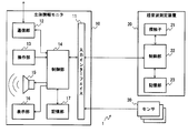
- FIG. 1 is a block diagram showing an internal configuration of a biological information measurement system according to a first exemplary embodiment.
- 3 is a diagram illustrating an example of a first mode screen and a second mode screen according to the first embodiment;
- FIG. 3 is a diagram illustrating an example of a first mode screen and a second mode screen according to the first embodiment;
- FIG. 3 is a diagram illustrating an example of a first mode screen and a second mode screen according to the first embodiment;
- FIG. 10 is a diagram illustrating an example of a display screen according to the second exemplary embodiment.
- FIG. 10 is a diagram illustrating an example of a display screen according to a third embodiment.
- FIG. 1 is a block diagram showing an internal configuration of a biological information measurement system according to a first exemplary embodiment.
- 3 is a diagram illustrating an example of a first mode screen and a second mode screen according to the first embodiment;
- FIG. 3 is a diagram illustrating an example of a first mode screen and a second mode screen
- FIG. 10 is a diagram illustrating an example of a layout change according to the third embodiment.
- FIG. 10 is a diagram illustrating an example of a layout change according to the third embodiment.
- FIG. 10 is a diagram illustrating an example of a layout change according to the third embodiment.
- FIG. 10 is a diagram illustrating an example of a layout change according to the third embodiment.
- FIG. 10 is a diagram illustrating an example of a layout change according to the third embodiment.
- FIG. 10 is a diagram illustrating an example of a layout change according to the third embodiment.
- FIG. 10 is a diagram illustrating an example of a layout change according to the third embodiment.
- FIG. 10 is a diagram illustrating an example of a layout change according to the third embodiment.
- FIG. 10 is a diagram illustrating an example of a layout change according to the third embodiment.
- FIG. 10 is a diagram illustrating an example of a layout change according to the third embodiment.
- FIG. 10 is a diagram illustrating an example of a layout change according to the third embodiment.
- FIG. 10 is a diagram illustrating an example of a layout change according to the third embodiment.
- FIG. 1 is a conceptual diagram showing an external configuration of a biological information measurement system 1 according to the present embodiment.
- the biological information measurement system 1 includes a biological information monitor 10 and an ultrasonic measurement device 20. Although not shown, the biological information monitor 10 is appropriately connected to a sensor 30 (described later) via cable lines C1 and C2.
- the biological information monitor 10 measures various vital signs based on biological signals acquired from various sensors 30 (described later in FIG. 2) connected to the subject.
- the sensor 30 connected to the subject is various sensors used for measuring vital signs.
- the sensor 30 includes a cuff used for blood pressure measurement, an electrode (dispo electrode, clip electrode, etc.) used for electrocardiogram measurement, an SpO2 probe, a mask for respiratory measurement, and the like.
- the sensor 30 may acquire a biological signal by an invasive technique.
- the vital sign to be measured is composed of, for example, blood pressure, body temperature, respiratory rate, arterial oxygen saturation, electrocardiogram, pulse rate, and the like.
- the biological information monitor 10 is a concept including a bedside monitor, a portable medical telemeter, a defibrillator with a measurement function such as an electrocardiogram, and the like. That is, the biological information monitor 10 can be interpreted as various medical devices that measure and display vital signs. In the following description, the biological information monitor 10 is described as a so-called bedside monitor.
- the biological information monitor 10 has connection ports (for example, connector insertion ports) that connect to various sensors 30.
- the ultrasonic measurement device 20 is a device that can be attached to and detached from the connection port.
- the ultrasonic measurement device 20 acquires an ultrasonic image inside the subject's living body by bringing a probe 21 (described later) into contact with the subject's living body.
- the ultrasonic measurement device 20 is a device having a weight and a size that can be grasped by a user (mainly a doctor), and has a form in which a cable is connected to a probe head of a general ultrasonic diagnostic device.
- the ultrasonic measurement device 20 may be configured to be connectable to the biological information monitor 10. That is, the ultrasonic measurement apparatus 20 is not limited to a wired connection as illustrated, and may perform data transmission / reception with the biological information monitor 10 through a wireless connection.
- FIG. 2 is a block diagram focusing on the electrical configuration of the biological information measurement system 1.
- the sensor 30 is a vital sign sensor connected (for example, pasted) to the living body of the subject as described above.
- the biological information monitor 10 includes an input interface 11, a communication unit 12, an operation unit 13, a control unit 14, a speaker 15, a display unit 16, and a storage unit 17. Although not explicitly shown, the biological information monitor 10 includes an internal power supply and the like as appropriate.
- the input interface 11 is the above-described connection port and its peripheral circuits.
- the input interface 11 supplies signals received from the sensor 30 and the ultrasonic measurement device 20 to the control unit 14.
- the input interface 11 transmits a signal from the biological information monitor 10 to the sensor 30 or the ultrasonic measurement device 20.
- the biological information monitor 10 receives an ultrasonic image (or a reception signal that is a basis of the ultrasonic image) from the ultrasonic measurement device 20.
- the communication unit 12 transmits / receives data to / from other devices (for example, a central monitor).
- the communication part 12 should just satisfy
- the communication unit 12 may perform communication processing using a wired cable.
- a user (mainly a doctor) performs input to the biological information monitor 10 via the operation unit 13.
- the operation unit 13 is, for example, a button, a knob, a rotary selector, a key, or the like provided on the housing of the biological information monitor 10. Input via the operation unit 13 is supplied to the control unit 14.
- Speaker 15 outputs various notification sounds including alarms.
- the speaker 15 performs notification according to the control of the control unit 14.
- the display unit 16 is a display provided on the housing of the biological information monitor 10 and its peripheral circuits.
- the display unit 16 displays various types of information about the subject. More specifically, the display unit 16 displays various vital sign information (waveforms and measurement values), a setting screen, and the like according to the control of the control unit 14 (see FIG. 1).
- the display unit 16 also displays an ultrasonic image according to the control of the control unit 14. Display control by the control unit 14 will be described later with reference to FIG.
- the operation unit 13 and the display unit 16 may have an integrated configuration (a configuration like a so-called touch panel).
- the storage unit 17 stores various programs (including system software and various application software) and data (including measured values and set values such as blood pressure and SpO2 and ultrasonic images described later) used by the control unit 14.
- the control unit 14 appropriately reads out programs and data from the storage unit 17. Further, the control unit 14 appropriately writes data to the storage unit 17.
- the storage unit 17 is a secondary storage device provided in the biological information monitor 10, for example, a hard disk provided in the biological information monitor 10.
- the storage unit 17 is not limited to the case where it is built in the biological information monitor 10, but has a configuration that can be attached to and detached from the biological information monitor 10 (for example, a USB (UniversalUniversSerial Bus) memory that can be attached to and removed from the biological information monitor 10). May be.
- the control unit 14 is a processing unit that performs various processes of the biological information monitor 10.
- the control unit 14 is composed of a CPU (Central Processing ⁇ ⁇ Unit) and its peripheral circuits, and realizes an operation by software or hardware. Specifically, the control unit 14 acquires vital sign information (waveforms such as blood pressure, SpO2, body temperature, and measured values) based on the biological signal acquired from the sensor 30, and alarms based on the vital sign information. Perform ringing control, etc.
- vital sign information waveforms such as blood pressure, SpO2, body temperature, and measured values
- the control unit 14 also includes a first mode in which a screen including vital sign information is displayed on the display unit 16 during monitoring of the subject, and a second mode in which a screen including ultrasonic image information is displayed on the display unit 16. , Switch. Details of the display switching will be described later with reference to FIG.
- the ultrasonic measurement device 20 is a device that can be attached to and detached from the biological information monitor 10 as shown in FIG.
- the ultrasonic measurement device 20 has a shape similar to a so-called probe.
- the ultrasonic measurement apparatus 20 includes a probe 21, a control unit 22, and a storage unit 23.
- the ultrasonic measurement device 20 may be a device that operates by receiving power supply from the biological information monitor 10 or may have a configuration having an internal power supply.
- the probe 21 contacts (or comes close to) the living body of the subject and irradiates ultrasonic waves.
- the probe 21 receives reflected ultrasonic waves (reflected waves).
- the probe 21 supplies the received ultrasonic waves to the control unit 22.
- the type of the probe 21 is not particularly limited. That is, the probe 21 may be any of a convex type, a sector type, a linear type, and other types.
- An operation interface (knob, button, operation wheel, etc.) may be provided on the housing of the probe 21. The user changes the setting of the probe 21 by operating this operation interface.
- the control unit 22 performs various settings of the probe 21 and capture of a received signal acquired by the probe 21.
- the processing of the control unit 22 includes the following. -Ultrasonic frequency setting of the probe 21-Beamforming setting of the probe 21-Reflected wave received by the probe 21 is calculated (matched addition of reflected echo signals) to form an ultrasonic reception beam Mode signal processing, sound signal reception, mode signal processing, CF signal processing, Doppler signal processing / scan processing, blood flow volume, respiratory rate, heart sound, fetal movement, etc.
- the control unit 22 transfers the ultrasonic image generated by the above processing to the biological information monitor 10.
- the control unit 22 may transfer the reflected wave signal acquired by the probe 21 to the biological information monitor 10 as it is.
- the control unit 14 performs ultrasonic image generation processing based on the reflected wave signal.
- the storage unit 23 stores various programs (including system software and various application software) and data (including history values and setting values of ultrasonic images) used by the control unit 22.
- the control unit 22 appropriately reads out programs and data from the storage unit 23.
- the control unit 22 appropriately writes data to the storage unit 23.
- the storage unit 23 is a secondary storage device provided in the ultrasonic measurement device 20, for example, a hard disk provided in the ultrasonic measurement device 20. Note that the storage unit 23 is not limited to being built in the ultrasonic measurement device 20, and is configured to be detachable from the ultrasonic measurement device 20 (for example, a USB (Universal Serial ⁇ ⁇ Bus) memory detachable from the ultrasonic measurement device 20). Etc.).
- the control unit 14 performs display control of vital sign information and ultrasonic images. Specifically, the control unit 14 switches between a first mode in which a screen including vital sign information is displayed on the display unit 16 and a second mode in which a screen including ultrasonic image information is displayed on the display unit 16.
- the control unit 14 may operate in other modes (third mode, -fourth mode, etc.) according to the operation of the operation unit 13. For example, the control unit 14 may shift to an operation mode in which various setting screens are displayed in response to pressing of the setting button.
- the screen in the first mode is a screen that displays vital sign information (for example, measured values and waveforms such as blood pressure, SpO2, respiration, body temperature, etc.). Various setting buttons and the like may be displayed on the screen of the first mode in addition to the vital sign information.
- the second mode screen is a screen different from the first mode screen and displays at least an ultrasound image.
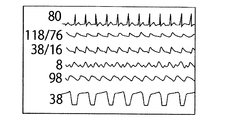
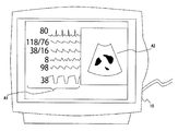
- FIG. 3A is a diagram illustrating an example of a screen in the first mode.
- the screen shown in the figure displays measured values and waveforms of various vital signs (blood pressure, SpO2, respiration, body temperature, etc.).
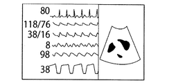
- FIG. 3B is a diagram illustrating a screen example of the second mode.
- an ultrasonic image acquired by operating the ultrasonic measurement apparatus 20 is displayed.
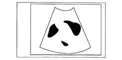
- FIG. 3C is a diagram illustrating another screen example of the second mode. Only the ultrasonic image acquired by the operation of the ultrasonic measurement device 20 is displayed on the screen shown in FIG. Note that a setting button or the like may be appropriately displayed on the second mode screen shown in FIG. 3B or 3C. That is, the screen in the second mode includes an ultrasonic image and is different from the screen in the first mode. Since it is preferable to always refer to vital sign information (measurement values and waveforms), the default display screen in the second mode is preferably in a display form as shown in FIG. 3B.
- the display in FIG. 3B is merely an example, and an ultrasonic image may be arranged in a so-called side cabinet.
- the window size for displaying the ultrasonic image may be changed by mouse cursor processing or the like.
- control unit 14 satisfies a predetermined condition when a predetermined event occurs in the operation modes (first mode and second mode) having different display targets (for example, (A) and (B) described later). Switch to the case (for example, (C), (D) described later). Details of mode switching will be described below.
- An example of the timing at which the control unit 14 switches between the first mode and the second mode is as follows.
- the user operates various operation interfaces (for example, buttons, knobs, dial type input unit, etc.) provided on the casing of the ultrasonic measurement device 20
- the ultrasonic measurement apparatus 20 transmits a switching signal.
- the control unit 14 performs mode switching when a switching signal is received from the ultrasonic measurement apparatus 20. Specifically, the control unit 14 switches to the second mode when receiving a switching signal during operation in the first mode. Similarly, the control unit 14 switches to the first mode when a switching signal is received during operation in the second mode.
- control unit 14 performs a mode switching process when the mode switching is instructed by the operation of the operation unit 13 of the biological information monitor 10.
- the operation unit 13 may be a touch panel or the like provided on the display screen of the biological information monitor 10 as described above, and is a button, knob, switch, or the like provided on the casing of the biological information monitor 10. Also good.
- the control unit 14 switches to the second mode when a switching instruction is issued during operation in the first mode. Similarly, the control unit 14 switches to the first mode when a switching signal is received during operation in the second mode.
- the operation interface for mode switching may be a device that can be attached to and detached from the ultrasonic measurement device 20 or the biological information monitor 10.
- the operation interface may be provided between the probe head of the ultrasonic measurement apparatus 20 and the connector insertion port.
- control unit 14 switches from the second mode to the first mode when the connection between the ultrasonic measurement device 20 and the biological information monitor 10 is completed (for example, when the connection is pulled out from the connector port of the biological information monitor 10). That is, when the ultrasonic measurement apparatus 20 is pulled out, the control unit 14 switches to the first mode in which vital signs are displayed mainly.
- the ultrasonic measurement device 20 converts the ultrasonic image or the reflected wave signal into the living body. It transmits to the information monitor 10.
- the ultrasonic measurement apparatus 20 transmits a reflected wave signal (hereinafter referred to as a reflected wave signal).
- the control unit 14 switches from the first mode to the second mode when the change is detected. That is, the control unit 14 switches to an operation mode (second mode) for displaying an ultrasonic image.
- the control unit 14 switches to the first mode in which the vital sign is displayed mainly.
- the analysis of the reflected wave signal is not limited to the comparison with the threshold value as described above, and may be performed using the signal change rate or the like.
- the reflected wave signal is transmitted from the ultrasonic measurement device 20, but the control unit 14 performs the same processing even when an ultrasonic image is transmitted from the ultrasonic measurement device 20. be able to.
- the control unit 14 may detect a temporal pixel change in the ultrasonic image and perform mode switching based on the pixel change.
- the biological information monitor 10 is connected via the sensor 30. Acquired various vital signs.
- the control unit 14 performs mode switching when the measured value of the vital sign is in a predetermined deterioration state.
- the predetermined deterioration state is a case where a certain vital sign has deteriorated over a long period of time (for example, over 5 minutes or more). And the number of vital signs is close to an abnormal value.
- the control unit 14 switches to the first mode and performs alarm sounding control and the like.
- the control unit 14 switches from the first mode to the second mode.
- the above is an example of the mode switching process by the control unit 14.
- the above (A) to (D) are merely examples, and mode switching may be performed in response to an event other than the above.
- the user may set at what timing the mode switching is performed from a setting screen (not shown). For example, the user can validate only the above-described (A) (validate only manual switching of the user).
- the user may define a new event or condition that causes mode switching (in other words, an event or condition other than the above (A) to (D) may be defined).
- the user may be able to make a setting to suppress switching between the first mode and the second mode.
- the user may perform the setting from the operation unit 13 of the biological information monitor 10, for example.
- the control unit 14 performs control so as not to switch between the first mode and the second mode.
- mode switching suppression is set, the user can continue to view the currently referenced screen. For example, when the user recognizes the deterioration of the vital sign but wants to confirm the cause of the pathological condition deterioration with the ultrasonic image, the user can continue to refer to the second mode for displaying the ultrasonic image.
- control unit 14 may perform the alarm ringing control via the speaker 15 as usual. Thereby, the user can continue to refer to the ultrasonic image while grasping the abnormality of the subject by the alarm sounding.
- the biological information measuring system 1 is configured to handle an ultrasound image
- the ultrasound image is often referred to temporarily for grasping the pathological condition of the subject.
- vital sign information for example, measured values and waveforms of blood pressure, SpO2, body temperature, respiratory rate, etc.
- the control unit 14 switches between the first mode for displaying vital sign information and the second mode for displaying an ultrasonic image. That is, the display unit 16 switches between a screen on which vital sign information is displayed and a screen on which an ultrasound image is displayed.
- the user can refer to both the vital sign information and the ultrasonic image by referring to both screens.
- information can be distributed between the first mode display screen and the second mode display screen. As a result, it is possible to avoid an excessive amount of information displayed in one screen.
- the mode switching of the control unit 14 occurs, for example, in the above (A) to (D).
- a predetermined event occurs or when a predetermined condition is satisfied (that is, in the case of (A) to (D) above)
- the user switches vital sign information or ultrasonic image at an appropriate timing.
- the mode is switched according to the operation of the operation interface (the above (A))
- the display can be switched at a timing desired by the user. As a result, the user can immediately access necessary information.
- control unit 14 may perform mode switching according to the attachment / detachment state of the ultrasonic measurement device 20 (the above (B)).
- the user can refer to the ultrasound image immediately after the ultrasound image can be acquired.
- the user can refer to only vital sign information immediately after the ultrasound image can no longer be acquired.
- the control unit 14 may switch the mode in accordance with the received signal (or ultrasonic image) from the ultrasonic measurement device 20 (the above (C)).
- the user can refer to the ultrasound image only when a useful ultrasound image can be acquired. That is, the user can refer to the ultrasound image only when it is useful to refer to it.
- the control unit 14 may switch the mode according to the state of the measured value of the vital sign (the above (D)). As a result, when the measured value of the vital sign is abnormal (or when there is a possibility of becoming abnormal), the vital sign information is preferentially displayed. As a result, the user can accurately grasp the deterioration of vital signs.
- the biological information monitor 10 according to the present embodiment is characterized in that a part of setting change processing is suppressed according to the current operation mode.
- the difference between the biological information measuring system 1 according to the present embodiment and the first embodiment will be described below.
- a processing unit having the same name and reference numeral as in the first embodiment performs the same processing as in the first embodiment unless otherwise specified (the same applies to the third embodiment). .
- the configuration of the biological information measurement system 1 is the same as that shown in FIG.
- the control unit 14 of the present embodiment prohibits (suppresses) the setting made via the operation unit 13 or the like according to the current operation mode (first mode or second mode). A detailed example will be described below.
- the control unit 14 suppresses the setting related to the acquisition of the ultrasonic image.
- the setting is, for example, a change setting of an ultrasonic diagnostic mode (B mode, M mode, D mode) or the like.
- the control unit 14 suppresses settings related to acquisition and display of vital signs.
- the setting relates to measurement of various vital signs (blood pressure, respiration, body temperature, SpO2), and is, for example, a setting related to the maximum pressurization value at the time of noninvasive blood pressure measurement.
- the control unit 14 performs a prohibited setting operation (when an ultrasonic setting operation is performed in the first mode, or when a setting operation related to vital signs is performed in the second mode.
- a message indicating that the setting cannot be performed may be displayed. The user can grasp that the prohibition operation is performed by referring to the message.
- the second mode when the second mode is set, settings related to vital sign measurement are suppressed.
- the second mode it is assumed that the user wants to refer to an ultrasonic image related to the subject.
- attention is directed to grasping the ultrasonic image rather than the vital sign.
- the settings related to vital signs it is possible to prevent the vital sign measurement process from operating with unintended settings.
- the biological information monitor 10 according to the present embodiment is characterized in that the layout of a screen that displays both ultrasonic images and vital sign information is changed under a predetermined condition. The difference between the biological information measuring system 1 according to the present embodiment and the first embodiment will be described below.
- the configuration of the biological information measurement system 1 according to the present embodiment is substantially the same as that of the first embodiment (FIG. 2). However, the display control of the control unit 14 is different. Details of the display control will be described.
- the control unit 14 displays a screen on which the ultrasonic image and vital sign information (waveform, measurement value) are displayed on the display unit 16.
- FIG. 5 is an example of the screen. As shown in the drawing, an area A1 where various vital signs are displayed and an area A2 where an ultrasonic image is displayed are displayed.
- control unit 14 can display only the area A1 in which the vital sign information is displayed when the ultrasonic measurement apparatus 20 is not connected to the biological information monitor 10. That is, the display unit 16 displays at least one of vital sign information and an ultrasonic image.
- control unit 14 does not necessarily have to perform mode switching (first mode, second mode).
- control unit 14 changes the layout of the screen being displayed when a predetermined event occurs.
- the predetermined event that triggers the layout change is, for example, as follows.
- the change in position indicates a change in the display position (coordinates) of the ultrasonic image.
- the control unit 14 changes the layout according to the display size and display position of the ultrasonic image.
- the layout change may be performed according to the following change rule, for example.
- Rule 1 The layout is changed so that the measured values (numerical values) of various vital signs are preferentially displayed as compared with the measured waveform.
- Rule 2 The layout is changed according to a preset priority.
- Rule 3 A predetermined abnormality Change the layout to preferentially display vital signs that are in a state (for example, an alarm should sound)
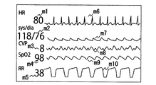
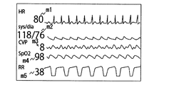
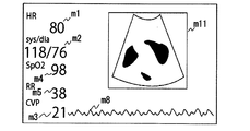
- FIG. 6A is a diagram showing a display screen before connection of the ultrasonic measurement device 20. Measurement values m1 to m5 and measurement waveforms m6 to m10 of various vital signs (heart rate (HR), blood pressure (sys / dia), CVP, SpO2, respiration rate (RR)) are displayed on the display screen.
- the control part 14 should just produce
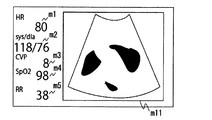
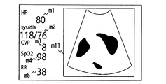
- FIG. 6A is a display screen example after the layout change.
- an ultrasonic image m11 is displayed on the display screen.
- control unit 14 may display the measurement waveform as much as possible according to the size of the ultrasonic image m11.
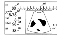
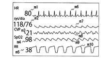
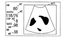
- FIG. 6C is an example in which an electrocardiogram waveform m6 is also displayed in addition to the display mode of FIG. 5B.
- the control unit 14 may change the layout so that as much information as possible can be displayed according to the size of the ultrasonic image m11.
- the size of the ultrasonic image m11 may be determined by default, or may be appropriately changed by a mouse operation or the like.
- rule 2 described above will be described.
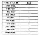
- the user defines in advance whether to preferentially display each vital sign.
- a definition example of priority display is shown in FIG.
- the priority may be set by default.
- FIG. 8A is a diagram showing a display screen before connection of the ultrasonic measurement apparatus 20.
- Various vital sign measurement values m1 to m5 and measurement waveforms m6 to m10 are displayed on the display screen.
- FIG. 8C is a diagram showing a layout example when the display size of the ultrasonic image m11 is smaller than that in FIG. 8B.
- FIG. 9A is a diagram showing a display screen before connection of the ultrasonic measurement device 20. Measurement values m1 to m5 of various vital signs and measurement waveforms m6 to m10 are displayed on the display screen.
- the control unit 14 acquires the size (for example, default size) of the ultrasonic image, and calculates the display area size of the vital sign based on the size.
- the control unit 14 preferentially displays the vital signs in an alarm state with respect to the vital sign display area, and then sequentially displays each measured value in the normal value range.
- CVP Central Venous Pressure
- a measurement waveform m8 is also displayed in addition to the CVP measurement value m3.
- the control unit 14 may perform control so that the measured value or waveform of the vital sign in an abnormal state is moved to a position where it can be easily seen (for example, near the center of the display). .
- the control unit 14 appropriately determines whether or not the measured value of each vital sign is an abnormal value during display of the ultrasonic image. When a vital sign that has become an abnormal value is detected, the control unit 14 changes the layout so that the detailed information of the vital sign is displayed.
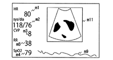
- FIG. 10A is a display screen when the measured value of each vital sign is normal. On the display screen, measured values m1 to m5 of each vital sign and an ultrasonic image m11 are displayed. Here, it is assumed that the measured value of SpO2 becomes an abnormal value (79% for a normal range of 90% or more).
- the control unit 14 detects this abnormal state, and changes the layout so as to display the detailed information of the vital sign that has entered the abnormal state.
- FIG. 10B is a display screen example after the layout change.
- the control unit 14 narrows the display area of the ultrasonic image m11 and changes the layout so that the SpO2 measurement waveform m9 is displayed in an empty space. As a result, the user can refer to the detailed information of SpO2 in an abnormal state.
- the layout change is merely an example, and the control unit 14 may change the layout using the rules corresponding to the rules 1 to 3 when the event (F) occurs.
- the control unit 14 changes the layout depending on whether or not a certain vital sign has an abnormal value. However, even if the vital sign does not have an abnormal value, the control unit 14 deteriorates in the long term (for example, the respiratory rate gradually increases).
- the layout may be changed when a state such as “decrease” is detected. That is, the control unit 14 may change the layout when the vital sign is in a predetermined deterioration state.
- the event that triggers the layout change is not limited to the above (E) and (F), and the layout may be changed with another event as a trigger.
- control unit 14 automatically changes the layout
- the control unit 14 confirms whether or not to change the layout on the screen ("Do you want to change the layout?" ? ")
- an operation button may be displayed, and the layout may be changed according to the input result of the operation button.
- the biological information monitor 10 When the biological information monitor 10 according to the present embodiment detects a predetermined event (the above (E), (F), etc.), the biological information monitor 10 displays a layout of a screen on which at least one of vital sign information and an ultrasonic image is displayed. Change (FIGS. 6A to 10B). Thereby, the biological information monitor 10 can provide an appropriate screen according to the state of the subject and the operation of the user.
- a predetermined event the biological information monitor 10 according to the present embodiment detects a predetermined event (the above (E), (F), etc.
- the biological information monitor 10 displays a layout of a screen on which at least one of vital sign information and an ultrasonic image is displayed. Change (FIGS. 6A to 10B).
- the biological information monitor 10 can provide an appropriate screen according to the state of the subject and the operation of the user.
- control unit 14 may change the layout in accordance with a predetermined rule (the above-described rules 1 to 3) when an event for which the layout is to be changed (the above (E), (F), etc.) occurs.
- a predetermined rule the above-described rules 1 to 3 when an event for which the layout is to be changed (the above (E), (F), etc.) occurs.
- the biological information monitor 10 can simultaneously display the ultrasonic image and the measured value of each vital sign. Thereby, the user can refer to the ultrasonic image while grasping the current state of the subject.
- the user can refer to information to be preferentially referred to on the display screen while referring to the ultrasonic image.
- the user can preferentially refer to the vital signs that should be referred to with particular care along with the ultrasound image.
- control unit 14 can be realized as a computer program that operates in the biological information monitor 10.
- Non-transitory computer readable media include various types of tangible storage media (tangible storage medium).
- Examples of non-transitory computer-readable media include magnetic recording media (eg flexible disks, magnetic tapes, hard disk drives), magneto-optical recording media (eg magneto-optical discs), CD-ROMs (Read Only Memory), CD-Rs, CD-R / W, semiconductor memory (for example, mask ROM, PROM (Programmable ROM), EPROM (Erasable ROM), flash ROM, RAM (random access memory)) are included.
- the program may also be supplied to the computer by various types of temporary computer-readable media. Examples of transitory computer readable media include electrical signals, optical signals, and electromagnetic waves.
- the temporary computer-readable medium can supply the program to the computer via a wired communication path such as an electric wire and an optical fiber, or a wireless communication path.
- control unit 14 can include a processor and a memory.
- the processor include a CPU and an MPU.
- the memory is configured to store computer readable instructions. Examples of the memory include a ROM in which various instructions are stored, and a RAM having a work area in which various instructions executed by the processor are stored.
Landscapes
- Health & Medical Sciences (AREA)
- Life Sciences & Earth Sciences (AREA)
- Engineering & Computer Science (AREA)
- Biomedical Technology (AREA)
- Public Health (AREA)
- General Health & Medical Sciences (AREA)
- Medical Informatics (AREA)
- Physics & Mathematics (AREA)
- Surgery (AREA)
- Biophysics (AREA)
- Molecular Biology (AREA)
- Heart & Thoracic Surgery (AREA)
- Animal Behavior & Ethology (AREA)
- Pathology (AREA)
- Veterinary Medicine (AREA)
- Nuclear Medicine, Radiotherapy & Molecular Imaging (AREA)
- Radiology & Medical Imaging (AREA)
- Cardiology (AREA)
- Theoretical Computer Science (AREA)
- General Engineering & Computer Science (AREA)
- Physiology (AREA)
- Epidemiology (AREA)
- Primary Health Care (AREA)
- Business, Economics & Management (AREA)
- General Business, Economics & Management (AREA)
- General Physics & Mathematics (AREA)
- Human Computer Interaction (AREA)
- Pulmonology (AREA)
- Emergency Medicine (AREA)
- Obesity (AREA)
- Vascular Medicine (AREA)
- Ultra Sonic Daignosis Equipment (AREA)
- Measuring And Recording Apparatus For Diagnosis (AREA)
Priority Applications (5)
| Application Number | Priority Date | Filing Date | Title |
|---|---|---|---|
| CN202210218336.XA CN114601427A (zh) | 2015-11-13 | 2016-10-05 | 患者监控器 |
| CN201680062612.0A CN108348159B (zh) | 2015-11-13 | 2016-10-05 | 患者监控器、生理信息测量系统、用于患者监控器的程序以及存储用于患者监控器的程序的永久计算机可读介质 |
| EP16863926.8A EP3375350A4 (en) | 2015-11-13 | 2016-10-05 | MONITOR FOR BIOLOGICAL INFORMATION, BIOLOGICAL INFORMATION MEASURING SYSTEM, PROGRAM FOR MONITOR FOR BIOLOGICAL INFORMATION AND NON-TEMPERATIVE COMPUTER-READABLE MEDIUM WITH A STORED PROGRAM FOR A MONITOR FOR BIOLOGICAL INFORMATION |
| US15/770,665 US12419611B2 (en) | 2015-11-13 | 2016-10-05 | Patient monitor, physiological information measurement system, program to be used in patient monitor, and non-transitory computer readable medium in which program to be used in patient monitor is stored |
| US19/235,705 US20250302444A1 (en) | 2015-11-13 | 2025-06-12 | Patient monitor, physiological information measurement system, program to be used in patient monitor, and non-transitory computer readable medium in which program to be used in patient monitor is stored |
Applications Claiming Priority (2)
| Application Number | Priority Date | Filing Date | Title |
|---|---|---|---|
| JP2015223061A JP6382174B2 (ja) | 2015-11-13 | 2015-11-13 | 生体情報モニタ、生体情報測定システム、及びプログラム |
| JP2015-223061 | 2015-11-13 |
Related Child Applications (2)
| Application Number | Title | Priority Date | Filing Date |
|---|---|---|---|
| US15/770,665 A-371-Of-International US12419611B2 (en) | 2015-11-13 | 2016-10-05 | Patient monitor, physiological information measurement system, program to be used in patient monitor, and non-transitory computer readable medium in which program to be used in patient monitor is stored |
| US19/235,705 Continuation US20250302444A1 (en) | 2015-11-13 | 2025-06-12 | Patient monitor, physiological information measurement system, program to be used in patient monitor, and non-transitory computer readable medium in which program to be used in patient monitor is stored |
Publications (1)
| Publication Number | Publication Date |
|---|---|
| WO2017081962A1 true WO2017081962A1 (ja) | 2017-05-18 |
Family
ID=58695141
Family Applications (1)
| Application Number | Title | Priority Date | Filing Date |
|---|---|---|---|
| PCT/JP2016/079690 Ceased WO2017081962A1 (ja) | 2015-11-13 | 2016-10-05 | 生体情報モニタ、生体情報測定システム、生体情報モニタで使用するプログラム、及び生体情報モニタで使用するプログラムが格納された非一時的なコンピュータ可読媒体 |
Country Status (5)
| Country | Link |
|---|---|
| US (2) | US12419611B2 (enExample) |
| EP (1) | EP3375350A4 (enExample) |
| JP (1) | JP6382174B2 (enExample) |
| CN (2) | CN114601427A (enExample) |
| WO (1) | WO2017081962A1 (enExample) |
Cited By (2)
| Publication number | Priority date | Publication date | Assignee | Title |
|---|---|---|---|---|
| WO2019031345A1 (ja) * | 2017-08-09 | 2019-02-14 | オムロンヘルスケア株式会社 | 画像表示プログラム、画像表示方法、及びコンピュータ装置 |
| US20220117581A1 (en) * | 2019-01-22 | 2022-04-21 | Nihon Kohden Corporation | Patient monitor and physiological information measurement system |
Families Citing this family (10)
| Publication number | Priority date | Publication date | Assignee | Title |
|---|---|---|---|---|
| JP7051391B2 (ja) | 2017-11-22 | 2022-04-11 | 日本光電工業株式会社 | 生体情報モニタ、及び生体情報システム |
| JP7149069B2 (ja) | 2017-12-26 | 2022-10-06 | 日本光電工業株式会社 | 携帯情報端末、センサ、生体情報管理方法、生体情報処理プログラム、およびコンピュータが読み取り可能な記憶媒体 |
| JP7014036B2 (ja) * | 2018-04-27 | 2022-02-01 | コニカミノルタ株式会社 | 情報処理装置及び画面切り替え方法 |
| JP2020022696A (ja) | 2018-08-09 | 2020-02-13 | 日本光電工業株式会社 | 生体情報測定装置、生体情報システム |
| EP3666195A1 (en) * | 2018-12-11 | 2020-06-17 | Koninklijke Philips N.V. | Ultrasound control unit |
| CN112912965A (zh) * | 2018-12-29 | 2021-06-04 | 深圳迈瑞生物医疗电子股份有限公司 | 一种对患者的监护方法及装置 |
| KR102670514B1 (ko) * | 2019-01-29 | 2024-05-30 | 삼성메디슨 주식회사 | 초음파 진단 장치 및 그 동작방법 |
| CN114159100A (zh) * | 2020-09-11 | 2022-03-11 | 深圳市理邦精密仪器股份有限公司 | 超声监护方法、超声设备及超声监护系统 |
| CN120000162A (zh) * | 2020-12-25 | 2025-05-16 | 深圳迈瑞生物医疗电子股份有限公司 | 监护设备、医疗中央站系统及监测数据的回顾方法 |
| CN116669618A (zh) * | 2020-12-25 | 2023-08-29 | 深圳迈瑞生物医疗电子股份有限公司 | 监护设备和用于监护设备的显示方法 |
Citations (3)
| Publication number | Priority date | Publication date | Assignee | Title |
|---|---|---|---|---|
| JPS5932444A (ja) * | 1982-08-17 | 1984-02-21 | 富士通株式会社 | 生体信号表示装置 |
| JPH11332865A (ja) * | 1998-05-28 | 1999-12-07 | Hitachi Medical Corp | 超音波診断装置 |
| JP2008073282A (ja) * | 2006-09-22 | 2008-04-03 | Toshiba Corp | 超音波画像診断装置 |
Family Cites Families (37)
| Publication number | Priority date | Publication date | Assignee | Title |
|---|---|---|---|---|
| JPH05228153A (ja) * | 1992-02-21 | 1993-09-07 | Ken Ishihara | 超音波診断装置 |
| JPH08256996A (ja) | 1995-03-24 | 1996-10-08 | Nippon Colin Co Ltd | 生体情報異常出力装置 |
| US5687717A (en) * | 1996-08-06 | 1997-11-18 | Tremont Medical, Inc. | Patient monitoring system with chassis mounted or remotely operable modules and portable computer |
| US6188407B1 (en) * | 1998-03-04 | 2001-02-13 | Critikon Company, Llc | Reconfigurable user interface for modular patient monitor |
| US6673018B2 (en) * | 2001-08-31 | 2004-01-06 | Ge Medical Systems Global Technology Company Llc | Ultrasonic monitoring system and method |
| US20080146925A1 (en) * | 2006-12-14 | 2008-06-19 | Ep Medsystems, Inc. | Integrated Electrophysiology and Ultrasound Imaging System |
| US6705992B2 (en) | 2002-02-28 | 2004-03-16 | Koninklijke Philips Electronics N.V. | Ultrasound imaging enhancement to clinical patient monitoring functions |
| US20040133115A1 (en) | 2002-11-01 | 2004-07-08 | Hamilton Emily F. | Method and apparatus for identifying heart rate feature events |
| US20070185390A1 (en) | 2003-08-19 | 2007-08-09 | Welch Allyn, Inc. | Information workflow for a medical diagnostic workstation |
| CN1879564A (zh) * | 2004-09-16 | 2006-12-20 | 通用电气公司 | 集成式麻醉监视和超声显示 |
| US20060058660A1 (en) * | 2004-09-16 | 2006-03-16 | Sandy Neal J | Integrated anesthesia monitoring and ultrasound display |
| US20070016029A1 (en) * | 2005-07-15 | 2007-01-18 | General Electric Company | Physiology workstation with real-time fluoroscopy and ultrasound imaging |
| US7569015B2 (en) * | 2005-07-15 | 2009-08-04 | General Electric Company | Integrated physiology and imaging workstation |
| US8317714B2 (en) * | 2005-08-19 | 2012-11-27 | Visualsonics Inc. | Systems and methods for capture and display of blood pressure and ultrasound data |
| US9805164B2 (en) * | 2006-05-01 | 2017-10-31 | Perigen, Inc. | Method and apparatus for providing contraction information during labour |
| JP2008167838A (ja) | 2007-01-10 | 2008-07-24 | Hitachi Medical Corp | 超音波診断装置及び超音波画像表示方法 |
| EP2252923A4 (en) * | 2008-03-08 | 2013-06-05 | Hewlett Packard Co | COMPUTER MONITOR WITH INTEGRAL KVM SWITCH |
| US20110157480A1 (en) * | 2008-05-07 | 2011-06-30 | Curl Douglas D | Integration system for medical instruments with remote control |
| WO2009138902A1 (en) | 2008-05-13 | 2009-11-19 | Koninklijke Philips Electronics N.V. | Integrated patient monitoring device |
| JP2009294800A (ja) * | 2008-06-03 | 2009-12-17 | Sony Corp | 医療支援システム、及び医療支援方法 |
| KR20100048359A (ko) * | 2008-10-31 | 2010-05-11 | 주식회사 메디슨 | 초음파 영상과 함께 부가 정보를 제공하는 초음파 시스템 |
| US8137273B2 (en) * | 2009-01-30 | 2012-03-20 | General Electric Company | Systems and methods for integrating hemodynamic and imaging examinations |
| US20120116218A1 (en) * | 2010-11-10 | 2012-05-10 | Jennifer Martin | Method and system for displaying ultrasound data |
| TWI430778B (zh) * | 2010-12-24 | 2014-03-21 | Pai Chi Li | 醫學成像系統及其醫學成像方法 |
| CN202313744U (zh) * | 2011-11-24 | 2012-07-11 | 谈晓明 | 具有心电监护功能的超声引导手术监视仪 |
| CN103544688B (zh) | 2012-07-11 | 2018-06-29 | 东芝医疗系统株式会社 | 医用图像融合装置和方法 |
| CN104736067A (zh) * | 2012-10-18 | 2015-06-24 | 皇家飞利浦有限公司 | 超声数据可视化装置 |
| EP2964095B1 (en) * | 2013-03-07 | 2017-05-10 | Koninklijke Philips N.V. | Multi-purpose ultrasound image acquisition device |
| WO2014141167A1 (en) | 2013-03-15 | 2014-09-18 | Koninklijke Philips N.V. | Monitor defibrillator with touch screen user interface for ecg review and therapy |
| CN104055532A (zh) * | 2013-03-19 | 2014-09-24 | 深圳迈瑞生物医疗电子股份有限公司 | 具有超声扫描监测功能的监护设备、超声装置及相应方法 |
| AU2014240821A1 (en) * | 2013-03-27 | 2015-11-05 | Realitygate (Pty) Ltd | A continuous + discrete control mechanism coordinated with decoupled object display |
| CN104161515B (zh) * | 2013-05-16 | 2015-06-10 | 上海联影医疗科技有限公司 | 磁共振成像方法和装置 |
| JP2015097687A (ja) | 2013-11-20 | 2015-05-28 | 日立アロカメディカル株式会社 | 超音波画像処理装置 |
| CN203852341U (zh) * | 2014-05-23 | 2014-10-01 | 向毓明 | 一种超声心电监护仪 |
| EP3197356B1 (en) * | 2014-09-22 | 2020-12-16 | Dexcom, Inc. | Method for mode switching |
| US11651857B2 (en) * | 2018-11-21 | 2023-05-16 | General Electric Company | Methods and apparatus to capture patient vitals in real time during an imaging procedure |
| JP2025032444A (ja) | 2023-08-28 | 2025-03-12 | 真嗣 寺川 | ビンゴスタンプラリー提供方法、ビンゴスタンプラリー提供サーバおよびビンゴスタンプラリー提供システム |
-
2015
- 2015-11-13 JP JP2015223061A patent/JP6382174B2/ja active Active
-
2016
- 2016-10-05 CN CN202210218336.XA patent/CN114601427A/zh active Pending
- 2016-10-05 US US15/770,665 patent/US12419611B2/en active Active
- 2016-10-05 WO PCT/JP2016/079690 patent/WO2017081962A1/ja not_active Ceased
- 2016-10-05 EP EP16863926.8A patent/EP3375350A4/en active Pending
- 2016-10-05 CN CN201680062612.0A patent/CN108348159B/zh active Active
-
2025
- 2025-06-12 US US19/235,705 patent/US20250302444A1/en active Pending
Patent Citations (3)
| Publication number | Priority date | Publication date | Assignee | Title |
|---|---|---|---|---|
| JPS5932444A (ja) * | 1982-08-17 | 1984-02-21 | 富士通株式会社 | 生体信号表示装置 |
| JPH11332865A (ja) * | 1998-05-28 | 1999-12-07 | Hitachi Medical Corp | 超音波診断装置 |
| JP2008073282A (ja) * | 2006-09-22 | 2008-04-03 | Toshiba Corp | 超音波画像診断装置 |
Non-Patent Citations (1)
| Title |
|---|
| See also references of EP3375350A4 * |
Cited By (2)
| Publication number | Priority date | Publication date | Assignee | Title |
|---|---|---|---|---|
| WO2019031345A1 (ja) * | 2017-08-09 | 2019-02-14 | オムロンヘルスケア株式会社 | 画像表示プログラム、画像表示方法、及びコンピュータ装置 |
| US20220117581A1 (en) * | 2019-01-22 | 2022-04-21 | Nihon Kohden Corporation | Patient monitor and physiological information measurement system |
Also Published As
| Publication number | Publication date |
|---|---|
| US20180296188A1 (en) | 2018-10-18 |
| JP6382174B2 (ja) | 2018-08-29 |
| US20250302444A1 (en) | 2025-10-02 |
| CN108348159A (zh) | 2018-07-31 |
| CN108348159B (zh) | 2022-04-12 |
| JP2017086664A (ja) | 2017-05-25 |
| EP3375350A1 (en) | 2018-09-19 |
| CN114601427A (zh) | 2022-06-10 |
| US12419611B2 (en) | 2025-09-23 |
| EP3375350A4 (en) | 2019-08-07 |
Similar Documents
| Publication | Publication Date | Title |
|---|---|---|
| JP6382174B2 (ja) | 生体情報モニタ、生体情報測定システム、及びプログラム | |
| EP3386395B1 (en) | Patient monitor, vital sign software control method, and program | |
| CN104055532A (zh) | 具有超声扫描监测功能的监护设备、超声装置及相应方法 | |
| US11980448B2 (en) | Apparatus and methods of monitoring maternal and fetal heart rate | |
| US11253160B2 (en) | Measuring apparatus and blood pressure measuring method | |
| CN105581790A (zh) | 测量装置、血压测量方法和程序 | |
| JP6761003B2 (ja) | 生体情報モニタ、生体情報測定システム、及びプログラム | |
| JP5221086B2 (ja) | 生体情報モニタ及び生体情報モニタ制御プログラム | |
| JP6385789B2 (ja) | 生体情報測定装置、生体情報表示方法、及びプログラム | |
| JP2017148364A (ja) | 生体情報表示装置 | |
| JP2017035473A (ja) | 生体情報測定装置、呼吸間隔表示方法、及びプログラム | |
| JP2017051594A (ja) | 生体情報測定システム、生体情報モニタ、及び超音波測定装置 | |
| WO2017098723A1 (en) | Patient monitor, vital sign software control method, and program | |
| JP7267754B2 (ja) | 生体情報モニタおよび生体情報測定システム | |
| JP2020081364A (ja) | 情報処理装置、システム、情報処理方法、およびプログラム | |
| JP6538249B2 (ja) | 生体情報測定装置、生体情報表示方法、及びプログラム | |
| US20220122444A1 (en) | Monitoring apparatus and method for operating same, monitor and computer storage medium |
Legal Events
| Date | Code | Title | Description |
|---|---|---|---|
| 121 | Ep: the epo has been informed by wipo that ep was designated in this application |
Ref document number: 16863926 Country of ref document: EP Kind code of ref document: A1 |
|
| WWE | Wipo information: entry into national phase |
Ref document number: 15770665 Country of ref document: US |
|
| NENP | Non-entry into the national phase |
Ref country code: DE |
|
| WWE | Wipo information: entry into national phase |
Ref document number: 2016863926 Country of ref document: EP |
|
| WWG | Wipo information: grant in national office |
Ref document number: 15770665 Country of ref document: US |