WO2017078129A1 - User terminal, radio base station and radio communication method - Google Patents
User terminal, radio base station and radio communication method Download PDFInfo
- Publication number
- WO2017078129A1 WO2017078129A1 PCT/JP2016/082773 JP2016082773W WO2017078129A1 WO 2017078129 A1 WO2017078129 A1 WO 2017078129A1 JP 2016082773 W JP2016082773 W JP 2016082773W WO 2017078129 A1 WO2017078129 A1 WO 2017078129A1
- Authority
- WO
- WIPO (PCT)
- Prior art keywords
- user terminal
- transmission
- signal
- reception
- unit
- Prior art date
Links
Images


Classifications
-
- H—ELECTRICITY
- H04—ELECTRIC COMMUNICATION TECHNIQUE
- H04L—TRANSMISSION OF DIGITAL INFORMATION, e.g. TELEGRAPHIC COMMUNICATION
- H04L27/00—Modulated-carrier systems
- H04L27/26—Systems using multi-frequency codes
- H04L27/2601—Multicarrier modulation systems
- H04L27/2602—Signal structure
-
- H—ELECTRICITY
- H04—ELECTRIC COMMUNICATION TECHNIQUE
- H04L—TRANSMISSION OF DIGITAL INFORMATION, e.g. TELEGRAPHIC COMMUNICATION
- H04L1/00—Arrangements for detecting or preventing errors in the information received
- H04L1/08—Arrangements for detecting or preventing errors in the information received by repeating transmission, e.g. Verdan system
-
- H—ELECTRICITY
- H04—ELECTRIC COMMUNICATION TECHNIQUE
- H04L—TRANSMISSION OF DIGITAL INFORMATION, e.g. TELEGRAPHIC COMMUNICATION
- H04L1/00—Arrangements for detecting or preventing errors in the information received
- H04L1/12—Arrangements for detecting or preventing errors in the information received by using return channel
- H04L1/16—Arrangements for detecting or preventing errors in the information received by using return channel in which the return channel carries supervisory signals, e.g. repetition request signals
- H04L1/18—Automatic repetition systems, e.g. Van Duuren systems
- H04L1/1867—Arrangements specially adapted for the transmitter end
- H04L1/1893—Physical mapping arrangements
-
- H—ELECTRICITY
- H04—ELECTRIC COMMUNICATION TECHNIQUE
- H04L—TRANSMISSION OF DIGITAL INFORMATION, e.g. TELEGRAPHIC COMMUNICATION
- H04L5/00—Arrangements affording multiple use of the transmission path
- H04L5/003—Arrangements for allocating sub-channels of the transmission path
- H04L5/0044—Arrangements for allocating sub-channels of the transmission path allocation of payload
-
- H—ELECTRICITY
- H04—ELECTRIC COMMUNICATION TECHNIQUE
- H04L—TRANSMISSION OF DIGITAL INFORMATION, e.g. TELEGRAPHIC COMMUNICATION
- H04L5/00—Arrangements affording multiple use of the transmission path
- H04L5/003—Arrangements for allocating sub-channels of the transmission path
- H04L5/0058—Allocation criteria
- H04L5/0064—Rate requirement of the data, e.g. scalable bandwidth, data priority
-
- H—ELECTRICITY
- H04—ELECTRIC COMMUNICATION TECHNIQUE
- H04L—TRANSMISSION OF DIGITAL INFORMATION, e.g. TELEGRAPHIC COMMUNICATION
- H04L5/00—Arrangements affording multiple use of the transmission path
- H04L5/003—Arrangements for allocating sub-channels of the transmission path
- H04L5/0078—Timing of allocation
- H04L5/0082—Timing of allocation at predetermined intervals
-
- H—ELECTRICITY
- H04—ELECTRIC COMMUNICATION TECHNIQUE
- H04L—TRANSMISSION OF DIGITAL INFORMATION, e.g. TELEGRAPHIC COMMUNICATION
- H04L5/00—Arrangements affording multiple use of the transmission path
- H04L5/0091—Signaling for the administration of the divided path
-
- H—ELECTRICITY
- H04—ELECTRIC COMMUNICATION TECHNIQUE
- H04W—WIRELESS COMMUNICATION NETWORKS
- H04W72/00—Local resource management
- H04W72/02—Selection of wireless resources by user or terminal
-
- H—ELECTRICITY
- H04—ELECTRIC COMMUNICATION TECHNIQUE
- H04W—WIRELESS COMMUNICATION NETWORKS
- H04W72/00—Local resource management
- H04W72/04—Wireless resource allocation
- H04W72/044—Wireless resource allocation based on the type of the allocated resource
-
- H—ELECTRICITY
- H04—ELECTRIC COMMUNICATION TECHNIQUE
- H04W—WIRELESS COMMUNICATION NETWORKS
- H04W72/00—Local resource management
- H04W72/20—Control channels or signalling for resource management
- H04W72/23—Control channels or signalling for resource management in the downlink direction of a wireless link, i.e. towards a terminal
-
- H—ELECTRICITY
- H04—ELECTRIC COMMUNICATION TECHNIQUE
- H04L—TRANSMISSION OF DIGITAL INFORMATION, e.g. TELEGRAPHIC COMMUNICATION
- H04L5/00—Arrangements affording multiple use of the transmission path
- H04L5/003—Arrangements for allocating sub-channels of the transmission path
- H04L5/0032—Distributed allocation, i.e. involving a plurality of allocating devices, each making partial allocation
-
- H—ELECTRICITY
- H04—ELECTRIC COMMUNICATION TECHNIQUE
- H04L—TRANSMISSION OF DIGITAL INFORMATION, e.g. TELEGRAPHIC COMMUNICATION
- H04L5/00—Arrangements affording multiple use of the transmission path
- H04L5/003—Arrangements for allocating sub-channels of the transmission path
- H04L5/0053—Allocation of signaling, i.e. of overhead other than pilot signals
Definitions
- the present invention relates to a user terminal, a radio base station, and a radio communication method in a next-generation mobile communication system.
- LTE Long Term Evolution
- Non-Patent Document 1 LTE-Advanced
- FRA Full Radio Access
- 4G, 5G, etc. LTE-Advanced
- inter-device communication M2M: Machine-to-Machine
- MTC Machine Type Communication
- 3GPP Third Generation Partnership Project
- MTC user terminals MTC UE (User Equipment)
- MTC UE User Equipment
- 3GPP TS 36.300 “Evolved Universal Terrestrial Radio Access (E-UTRA) and Evolved Universal Terrestrial Radio Access Network (E-UTRAN); Overall description; Stage 2”
- 3GPP TS 36.888 “Study on provision of low-cost Machine-Type Communications (MTC) User Equipments (UEs) based on LTE (Release 12)”
- MTC Machine-Type Communications
- UEs User Equipments
- LC-MTC Low-Cost MTC user terminals
- LC-MTC UE LTE communication in a very narrow band
- NB-IoT Near Band Internet of Things
- NB-LTE Narrow Band LTE
- NB cellular IoT Narrow Band cellular Internet of Things
- NB-IoT described in this specification includes the above-mentioned NB-LTE, NB cellular IoT, clean slate, and the like.
- a user terminal (hereinafter referred to as an NB-IoT terminal) that communicates using NB-IoT has transmission / reception performance in a band (for example, 180 kHz) narrower than the minimum system bandwidth (1.4 MHz) supported by the existing LTE system. It has been studied as a user terminal.
- Such an NB-IoT terminal is required to reduce transmission / reception of unnecessary signals and suppress power consumption.
- control information and data are limited due to the band limitation. It takes a long time to transmit and receive, and as a result, power consumption may increase.
- the present invention has been made in view of such a point, and a user who can suppress the communication overhead even when the use band is limited to a band narrower than the minimum system bandwidth of the existing LTE system.
- An object is to provide a terminal, a radio base station, and a radio communication method.
- a user terminal is based on a transmission / reception unit that performs transmission and / or reception of a signal with a wireless base station based on a pattern including a plurality of wireless resources, and based on user terminal specific information And a control unit that determines a pattern from a plurality of patterns.
- the communication overhead can be suppressed even when the use band is limited to a band narrower than the minimum system bandwidth of the existing LTE system.
- NB-IoT terminals In NB-IoT terminals, it has been studied to allow a reduction in processing capability and simplify the hardware configuration. For example, in the NB-IoT terminal, the peak rate is reduced, the transport block size (TBS: Transport Block Size) is limited, the resource block (RB: Resource Block, PRB: Physical) compared to the existing user terminal (LTE terminal). Application of restrictions such as Resource Block (also called Resource Block) and reception RF (Radio Frequency) restrictions are under consideration.
- TBS Transport Block Size
- RB Resource Block
- PRB Physical
- the upper limit of the use band of the NB-IoT terminal is a predetermined narrow band (for example, 180 kHz) 1 PRB, 1.4 MHz, etc.).
- the upper limit of the use band of the NB-IoT terminal is a predetermined narrow band (for example, 180 kHz) 1 PRB, 1.4 MHz, etc.).
- NB-IoT terminals with limited bandwidths are being considered to operate within the LTE / LTE-A system band.
- an NB-IoT terminal may be represented as a terminal whose maximum supported band is the same as or a part of the minimum band supported by the existing LTE (for example, 1.4 MHz).
- the terminal may be expressed as a terminal having a transmission / reception performance that is the same as the minimum system band (for example, 1.4 MHz) supported by LTE / LTE-A or narrower than the minimum system band.
- FIG. 1 is a diagram showing an example of arrangement of narrow bands in the system band.
- a predetermined narrow band for example, 180 kHz
- the narrow band corresponds to a frequency band that can be detected by the NB-IoT terminal.
- the minimum system band (1.4 MHz) of the LTE system is LTE Rel. It is also the use band of 13 LC-MTCs.
- the narrow band frequency position used by the NB-IoT terminal can be changed within the system band.
- the NB-IoT terminal preferably communicates using different frequency resources for each predetermined period (for example, subframe).
- the NB-IoT terminal preferably has an RF retuning function in consideration of application of frequency hopping and frequency scheduling.
- DL NB Downlink Narrow Band
- UL NB Uplink Narrow Band
- the NB-IoT terminal receives downlink control information (DCI: Downlink Control Information) using a downlink control signal (downlink control channel) arranged in a narrow band, and the downlink control signal is received by EPDCCH (Enhanced Physical Downlink Control). Channel), M-PDCCH (MTC PDCCH), or NB-PDCCH.
- DCI Downlink Control Information
- EPDCCH Enhanced Physical Downlink Control
- M-PDCCH MTC PDCCH
- NB-PDCCH NB-PDCCH.
- the NB-IoT terminal receives downlink data using a downlink data signal (downlink shared channel) arranged in a narrow band, but the downlink data signal may be called PDSCH (Physical Downlink Shared Channel). It may be called M-PDSCH (MTC PDSCH) or NB-PDSCH.
- PDSCH Physical Downlink Shared Channel
- MTC PDSCH Physical Downlink Shared Channel
- uplink control signals for NB-IoT terminals (for example, PUCCH (Physical Uplink Control Channel)) and uplink data signals (uplink shared channels) (for example, PUSCH (Physical Uplink Shared Channel)) are respectively It may be called M-PUCCH (MTC PUCCH), M-PUSCH (MTC PUSCH), NB-PUSCH, or the like.
- MTC PUCCH Physical Uplink Control Channel
- MTC PUSCH Physical Uplink Shared Channel
- NB-PUSCH Physical Uplink Shared Channel
- the channels used by NB-IoT terminals are not limited to the above channels, and “M” indicating MTC, “N” indicating NB-IoT, or “NB” is added to the conventional channels used for the same application. May be represented.
- SIB System Information Block
- MTC-SIB MTC-SIB
- NB-SIB NB-SIB
- NB-IoT in order to extend coverage, it is also considered to perform repeated transmission / reception in which the same downlink signal and / or uplink signal is transmitted / received over a plurality of subframes.
- the number of subframes in which the same downlink signal and / or uplink signal is transmitted / received is also referred to as a repetition number.
- the number of repetitions may be indicated by a repetition level.
- the repetition level is also referred to as a coverage enhancement (CE) level.
- CE coverage enhancement
- the use band is limited to the same or narrower band as the minimum system bandwidth of the existing LTE system as described above
- DCI downlink control information
- MCS Modulation and Coding Scheme
- RRC Radio Resource Control
- the use band of the NB-IoT terminal is limited to 180 kHz (one resource block (PRB)), which is a narrower band than the minimum system bandwidth (1.4 MHz) of the existing LTE system.
- PRB resource block
- application of the present invention is not limited to this.
- an NB-IoT terminal limited to the same band as the minimum system bandwidth (1.4 MHz) of an existing LTE system, or an NB- whose usage band is limited to a band narrower than 180 kHz.
- the present invention can also be applied to an IoT terminal.
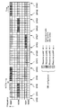
- FIG. 2 is a diagram illustrating a state in which a plurality of resource pools (patterns) used for uplink / downlink transmission are arranged.
- resource pools # 1- # 4 resource pools assigned to the same cell are arranged.
- Each resource pool can allocate radio resources for at least one of a downlink control channel, a downlink shared data channel, and an uplink shared data channel.
- the resource pool # 1 includes subbands SF # 1-SF # 6 of narrowband NB # 1, subframes SF # 8-SF # 13 of narrowband NB # 4, and subframes SF # of narrowband NB # 7. 15-SF # 20, narrowband NB # 1 subframes SF # 29-SF # 34, and narrowband NB # 4 subframes SF # 36-SF # 41.
- the resource pool # 2 includes subbands SF # 1-SF # 6 of narrowband NB # 4, subframes SF # 8-SF # 13 of narrowband NB # 7, and subframes SF # 22-SF of narrowband NB # 1. # 27, narrowband NB # 4 subframes SF # 29-SF # 34, and narrowband NB # 7 subframes SF # 36-SF # 41.
- the resource pool # 3 includes subbands SF # 1-SF # 6 of the narrowband NB # 7, subframes SF # 15-SF # 20 of the narrowband NB # 1, and subframes SF # 22-SF # 27 of the narrowband NB # 4.
- the subbands include narrowband NB # 4 subframes SF # 29 to SF # 34 and narrowband NB # 7 subframes SF # 36 to SF # 41.
- the resource pool # 4 includes narrowband NB # 1 subframes SF # 8-SF # 13, narrowband NB # 4 subframes SF # 15-SF # 20, and narrowband NB # 7 subframes SF # 22-SF # 27. Narrowband NB # 1 subframes SF # 36 to SF # 41.
- a group of radio resources (6 PRB radio resource sets in FIG. 2) that are continuous for a certain period have different narrow bands (in FIG. 2, narrow bands NB # 1, NB # 4, NB).
- # 7) is frequency hopping.
- the groups may be frequency hopped into different narrow bands at a predetermined period (in FIG. 2, 7 subframe periods).
- the narrow band of the resource pool may be different for each subframe.
- the resource pool may not be arranged in an arbitrary period. For example, in FIG. 2, the resource pool # 1 is not allocated to any radio resource during the period of the subframes SF # 21- # 27.
- 1 PRB that does not belong to any group is set between groups (for example, narrow band NB # located between resource pools # 1 and # 2). 1 subframe SF # 7).
- the radio base stations forming the cell receive the arrangement of the resource pools # 1- # 4 from the radio base station as cell specific information (Cell Specific Information). Notify NB-IoT terminal.
- the NB-IoT terminal determines the allocation of resource pools # 1- # 4 from the received cell specific information.
- the radio base station can notify (configure) the arrangement of resource pools # 1- # 4 using SIB (System Information Block).
- SIB System Information Block
- the allocation of the resource pools # 1- # 4 can be notified by a notification signal.
- the allocation of resource pools # 1 to # 4 can be notified using radio resources that can be commonly received by all NB-IoT terminals that communicate with the radio base stations constituting the cell.
- the arrangement of the resource pools # 1- # 4 may include at least resource block information used for the resource pool.
- the arrangement of resource pools # 1- # 4 may be associated with a cell ID (Identification) or a subframe number. Further, not only one of SIB, cell ID, and subframe number, but also the arrangement of resource pools # 1- # 4 is associated by combining at least two of these and notified to the NB-IoT terminal. May be.
- the NB-IoT terminal determines (specifies and detects) a resource pool corresponding to the own terminal from the resource pools # 1 to # 4 based on the UE specific information (User Equipment Specific Information).
- UE specific information for example, a UE-specific parameter, a random access channel resource or a UE ID (User Equipment Identification) can be used.
- each of resource pools # 1- # 4 is associated with UE-specific information.
- a random access channel resource may be a PRACH (Physical Random Access Channel) resource.
- PRACH Physical Random Access Channel
- a PRACH resource may be a so-called sequence as a code resource, a time for identifying a resource, a subframe, or a combination thereof.
- the overhead of individual higher layer signaling and downlink control information (DCI) for the NB-IoT terminal is reduced. Can be reduced. For example, assigning UE-specific radio resources (PRB) for frequency hopping by higher layer signaling or instructing RB (narrow band) by DCI can be omitted.
- DCI downlink control information
- notification of the allocation of resource pools # 1- # 4 using the cell specific information may be omitted, and the allocation of the resource pool corresponding to the own terminal may be specified from the UE specific information.
- frequency hopping may be possible in the same resource pool.
- the presence / absence of frequency hopping may be notified to the NB-IoT terminal using 1 bit of downlink control information.
- the radio base station performs control so that a predetermined number of NB-IoT terminals are allocated to other resource pools.
- the resource pool number may be shifted by “1” between a radio base station and a predetermined number of NB-IoT terminals.
- Offset information can be used when shifting the resource pool number. For example, when the 1-bit offset information is “1”, the resource pool number may be incremented by 1, and when it is “0”, the resource pool number may be maintained as it is. By using offset information in this way, the resource pool can be dynamically changed with a small amount of information.
- the shift amount is not limited to 1 and may be 2 or 3. Alternatively, the shift amount may be designated by higher layer signaling.
- the second aspect relates to downlink transmission, and as shown in FIG. 3, a plurality of resource pools (patterns) used for downlink transmission are arranged.
- a plurality of resource pools (patterns) used for downlink transmission are arranged.
- three DL resource pools (DL resource pool # 1- # 3) allocated to the same cell are arranged.
- Each resource pool can be assigned a radio resource of at least one of a downlink control channel (for example, M-PDCCH) and a downlink shared data channel.
- a downlink control channel for example, M-PDCCH
- DL resource pool # 1 includes subbands SF # 1-SF # 6 of narrowband NB # 1, subframes SF # 15-SF # 20 of narrowband NB # 7, and subframes SF of narrowband NB # 1.
- # 22-SF # 27 and narrowband NB # 7 subframes SF # 36-SF # 41.
- the DL resource pool # 2 includes the narrowband NB # 7 subframe SF # 1-SF # 6, the narrowband NB # 81 subframe SF # 8-SF # 13, and the narrowband NB # 7 subframe SF # 22-. It includes SF # 27 and narrowband NB # 1 subframes SF # 29-SF # 34.
- the DL resource pool # 3 includes narrowband NB # 7 subframe SF # 8-SF # 13, narrowband NB # 1 subframe SF # 15-SF # 20, and narrowband NB # 7 subframe SF # 29-. This includes SF # 34 and narrowband NB # 1 subframes SF # 36-SF # 41.
- the arrangement of the above DL resource pools # 1- # 3 is notified from the radio base station to the NB-IoT terminal using the cell specific information as in the first mode described above.
- the arrangement of the DL resource pools # 1- # 4 is notified (configured) using an SIB (System Information Block), and the arrangement of the resource pools # 1- # 4 is associated with a cell ID (Identification) and a subframe number.
- SIB System Information Block
- the arrangement of resource pools # 1- # 4 is associated by combining at least two of these and notified to the NB-IoT terminal. May be.
- the NB-IoT terminal can specify the arrangement of the DL resource pools # 1- # 3 with the cell specific information.
- each of the DL resource pools # 1- # 3 is associated with UE-specific information.
- PRACH resources are used as UE specific information.
- DL resource pool # 1 is associated with PRACH resources # 0 to # X-1
- DL resource pool # 2 is associated with PRACH resources #X to # Y-1
- DL Resource pool # 3 is associated with PRACH resources #Y to # Z-1.
- the NB-IoT terminal can determine (specify and detect) the DL resource pool to which the terminal belongs to from the UE specific information.
- the PRACH resource may be applied with a so-called sequence as a code resource, or may be applied with a time or subframe for specifying the resource, or a combination thereof. Also good.
- FIG. 4 is a diagram for explaining a specific example in the case where the NB-IoT terminal uses PRACH resource # 0 in FIG.
- the NB-IoT terminal determines (specifies and detects) that the DL resource pool assigned to the terminal is the DL resource pool # 1. For this reason, the NB-IoT terminal monitors the DL resource pool # 1, and, for example, as shown in FIG. 4, the downlink control information (DCI) is assigned to the subbands SF # 1- # 3 of the narrowband # 1. If so, the DCI is demodulated.
- DCI downlink control information
- DCI specifies the modulation and coding scheme (MCS: Modulation and Coding Scheme) and transport block size (TBS) of the downlink data signal.
- MCS Modulation and Coding Scheme
- TBS transport block size
- the resource allocation information the number of subframes to which the TBS is mapped and the subframe position may be specified.
- a repetition number indicating the number of subframes to which the same downlink signal is assigned may be designated. For example, when 1 bit of DCI is used and this bit is “1”, it indicates that the same downlink signal is allocated over a plurality of subframes, and when it is “0”. , It may be indicated that the repetition is not performed.
- FIG. 4 shows that DCI transmits a data signal assigned to the downlink shared data channel in narrowband NB # 7 subframe SR # 15-20. For this reason, the NB-IoT terminal can demodulate the data signal assigned to the subband SR # 15-20 of the narrowband NB # 7.
- the DL source pool may be dynamically changed using the offset information.
- the NB-IoT terminal uses the subband SF # 22- # 27 of the narrowband NB # 7 belonging to the DL resource pool # 2.
- the downlink shared data channel signal can be received.
- frequency hopping may be possible in the same DL resource pool.
- the presence / absence of frequency hopping may be notified to the NB-IoT terminal using 1 bit of downlink control information.
- the amount of downlink resource allocation information can be suppressed, and the overhead of downlink transmission can be reduced.
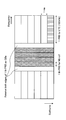
- the third aspect relates to downlink transmission, and in particular, performs DL resource allocation for one TBS in a frequency band narrower than 1 PRB (Physical Resource Block).
- PRB Physical Resource Block
- the technology supports downlink transmission with a granularity smaller than 1 PRB.
- FIG. 5A shows an example in which resource block allocation is defined by 3-bit downlink control information (DCI).
- DCI downlink control information
- the resource block allocation indicated by 3 bits basically indicates how many subframes are allocated from the top. For example, when DCI indicates “000”, one PRB is divided into two by 6 subcarriers (in FIG. 5B, the lower frequency sub-resource block # 0) is allocated. When DCI indicates “001”, the other sub-resource block # 1 is allocated.
- DCI downlink control information
- DL resource allocation can be performed in a frequency band narrower than 1 PRB (Physical Resource Block). For this reason, for example, it is possible to support resource allocation in a narrower band than 180 kHz, 1 PRB, and the like.
- PRB Physical Resource Block
- the fourth aspect relates to uplink transmission.
- a plurality of resource pools (patterns) used for uplink transmission are arranged.
- four UL resource pools (UL resource pool # 1- # 4) allocated to the same cell are arranged.
- Each resource pool can allocate radio resources for the uplink shared data channel.
- each UL resource pool # 1- # 4 is the same as in the first mode, and detailed description thereof is omitted. Also, the point that the allocation of UL resource pools # 1- # 4 is notified by cell-specific information and the point that each UL resource pool is associated with UE-specific information are the same as in the second aspect, Description of these is also omitted.
- contention-based transmission and non-contention-based transmission can be switched and applied.
- Contention-based transmission is such that the NB-IoT terminal determines (identifies and detects) a UL resource pool from UE-specific information and autonomously transmits data even when there is no UL grant.
- Non-contention based transmission is performed using radio resources specified by the UL grant, and can be transmitted as soon as possible (for example, a predetermined time (4 ms) after receiving the UL grant). Radio resources).
- Switching between contention-based transmission and non-contention-based transmission can be performed using upper layer signaling (for example, RRC (Radio Resource Control) signaling or broadcast information), for example.
- RRC Radio Resource Control
- the DL source pool may be dynamically changed using the offset information as in the first and second modes.
- frequency hopping may be possible in the same DL resource pool.
- it may be possible to set whether or not to specify the number of repetitions using a specific 1 bit, and to transmit a signal corresponding to this.
- the amount of uplink resource allocation information can be suppressed, and the overhead of downlink transmission can be reduced.
- the fifth aspect relates to uplink transmission, and particularly assigns narrowband subcarriers extended in the time direction by shortening the subcarrier interval.
- M-PRB in the case where the subcarrier interval 15 kHz is shortened to 2.5 kHz is shown. For this reason, the narrowband subcarrier is multiplied by 6 in the time direction.
- 1PRB (180 kHz) of LTE is shown on the left and right sides of the central portion of FIG.
- Narrowband subcarrier (1M-PRB) is 2.5 kHz ⁇ 12 subcarriers and 30 kHz. However, not all of these six M-PRBs are used, but the M-PRBs at both ends are used as guards as shown in FIG. Thereby, interference with an adjacent radio
- the central 4M-PRB is used for radio resource allocation.
- 3-bit information that can specify six patterns is used.
- 1M-PRB extended in the time direction can be effectively used by shortening the subcarrier interval.
- NB-IoT UE NB-IoT terminal
- the present invention is not limited to this.
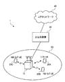
- FIG. 8 is a schematic configuration diagram of a wireless communication system according to an embodiment of the present invention.
- the wireless communication system 1 illustrated in FIG. 8 is an example in which an LTE system is employed in a network domain of a machine communication system.
- carrier aggregation (CA) and / or dual connectivity (DC) in which a plurality of basic frequency blocks (component carriers) having the system bandwidth of the LTE system as one unit can be applied.
- CA carrier aggregation
- DC dual connectivity
- the LTE system is set to a system band from a minimum of 1.4 MHz to a maximum of 20 MHz for both downlink and uplink, the present invention is not limited to this configuration.
- the wireless communication system 1 includes SUPER 3G, LTE-A (LTE-Advanced), IMT-Advanced, 4G (4th generation mobile communication system), 5G (5th generation mobile communication system), FRA (Future Radio Access), etc. May be called.
- the wireless communication system 1 includes a wireless base station 10 and a plurality of user terminals 20A, 20B, and 20C that are wirelessly connected to the wireless base station 10.
- the radio base station 10 is connected to the higher station apparatus 30 and is connected to the core network 40 via the higher station apparatus 30.
- the upper station device 30 includes, for example, an access gateway device, a radio network controller (RNC), a mobility management entity (MME), and the like, but is not limited thereto.
- a plurality of user terminals 20 (20A-20C) can communicate with the radio base station 10 in the cell 50.
- the user terminal 20A is a user terminal (hereinafter, LTE terminal) that supports LTE (up to Rel-10) or LTE-Advanced (including Rel-10 and later), and the other user terminals 20B and 20C are machine An NB-IoT UE that is a communication device in a communication system.
- LTE terminal up to Rel-10
- LTE-Advanced including Rel-10 and later
- the other user terminals 20B and 20C are machine An NB-IoT UE that is a communication device in a communication system.
- the user terminals 20 ⁇ / b> A, 20 ⁇ / b> B, and 20 ⁇ / b> C are simply referred to as the user terminal 20 unless it is necessary to distinguish between them.
- the NB-IoT UEs 20B and 20C are user terminals whose use bandwidth is limited to a narrower band than the minimum system bandwidth supported by the existing LTE system.
- the NB-IoT UEs 20B and 20C may be terminals compatible with various communication methods such as LTE and LTE-A, and are not limited to fixed communication terminals such as an electric meter, a gas meter, and a vending machine. It may be a mobile communication terminal. Further, the user terminal 20 may communicate directly with another user terminal 20 or may communicate via the radio base station 10.
- orthogonal frequency division multiple access (OFDMA) is applied to the downlink, and single carrier-frequency division multiple access (SC-FDMA) is used for the uplink.
- Carrier Frequency Division Multiple Access is applied.
- OFDMA is a multi-carrier transmission scheme that performs communication by dividing a frequency band into a plurality of narrow frequency bands (subcarriers) and mapping data to each subcarrier.
- SC-FDMA is a single-carrier transmission scheme that reduces interference between terminals by dividing the system bandwidth into bands consisting of one or continuous resource blocks for each terminal and using a plurality of terminals with mutually different bands. is there.
- the uplink and downlink radio access methods are not limited to these combinations.
- downlink channels include a downlink shared channel (PDSCH) shared by each user terminal 20, a broadcast channel (PBCH: Physical Broadcast Channel), a downlink L1 / L2 control channel, and the like. Used. User data, higher layer control information, and predetermined SIB (System Information Block) are transmitted by PDSCH. Also, MIB (Master Information Block) is transmitted by PBCH.
- PDSCH downlink shared channel
- PBCH Physical Broadcast Channel
- SIB System Information Block
- Downlink L1 / L2 control channels include PDCCH (Physical Downlink Control Channel), EPDCCH (Enhanced Physical Downlink Control Channel), PCFICH (Physical Control Format Indicator Channel), PHICH (Physical Hybrid-ARQ Indicator Channel), and the like.
- Downlink control information (DCI: Downlink Control Information) including scheduling information of PDSCH and PUSCH is transmitted by PDCCH.
- the number of OFDM symbols used for PDCCH is transmitted by PCFICH.
- the HAICH transmission confirmation information (ACK / NACK) for PUSCH is transmitted by PHICH.
- the EPDCCH is frequency-division multiplexed with the PDSCH, and is used for transmission of DCI and the like as with the PDCCH.
- an uplink shared channel (PUSCH: Physical Uplink Shared Channel) shared by each user terminal 20, an uplink L1 / L2 control channel (PUCCH: Physical Uplink Control Channel), a random access channel (PRACH: Physical Random Access Channel) is used.
- PUSCH may be referred to as an uplink data channel.
- User data and higher layer control information are transmitted by PUSCH.
- downlink radio quality information (CQI: Channel Quality Indicator), delivery confirmation information (ACK / NACK), and the like are transmitted by PUCCH.
- CQI Channel Quality Indicator
- ACK / NACK delivery confirmation information
- a random access preamble for establishing connection with a cell is transmitted by the PRACH.
- MTC terminal / NB-IoT UE may be indicated with “M” indicating MTC or “N” indicating NB-IoT, for example, for MTC terminal / NB-IoT UE.
- EPDCCH, PDSCH, PUCCH, PUSCH may be referred to as M-PDCCH, M-PDSCH, M-PUCCH, M-PUSCH, etc., respectively.
- a cell-specific reference signal CRS
- CSI-RS channel state information reference signal
- DMRS demodulation reference signal
- PRS Positioning Reference Signal
- a measurement reference signal SRS: Sounding Reference Signal
- a demodulation reference signal DMRS
- the DMRS may be referred to as a user terminal specific reference signal (UE-specific Reference Signal). Further, the transmitted reference signal is not limited to these.
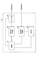
- FIG. 9 is a diagram illustrating an example of the overall configuration of a radio base station according to an embodiment of the present invention.
- the radio base station 10 includes at least a plurality of transmission / reception antennas 101, an amplifier unit 102, a transmission / reception unit 103, a baseband signal processing unit 104, a call processing unit 105, and a transmission path interface 106.
- User data transmitted from the radio base station 10 to the user terminal 20 via the downlink is input from the higher station apparatus 30 to the baseband signal processing unit 104 via the transmission path interface 106.
- PDCP Packet Data Convergence Protocol
- RLC Radio Link Control
- MAC Medium Access
- Retransmission control for example, HARQ (Hybrid Automatic Repeat reQuest) transmission processing
- HARQ Hybrid Automatic Repeat reQuest
- the downlink control signal is also subjected to transmission processing such as channel coding and inverse fast Fourier transform, and transferred to each transmitting / receiving unit 103.
- Each transmission / reception unit 103 converts the baseband signal output by precoding from the baseband signal processing unit 104 for each antenna to a radio frequency band and transmits the converted signal.
- the transmission / reception unit 103 can be configured by a transmitter / receiver, a transmission / reception circuit, or a transmission / reception device which is described based on common recognition in the technical field according to the present invention.
- the transmission / reception part 103 may be comprised as an integral transmission / reception part, and may be comprised from a transmission part and a receiving part.
- the radio frequency signal frequency-converted by the transmission / reception unit 103 is amplified by the amplifier unit 102 and transmitted from the transmission / reception antenna 101.
- the transmission / reception unit 103 can transmit and receive various signals with a narrow bandwidth (for example, 180 kHz) limited by the system bandwidth (for example, one component carrier).
- the radio frequency signal received by each transmitting / receiving antenna 101 is amplified by the amplifier unit 102.
- Each transmitting / receiving unit 103 receives the upstream signal amplified by the amplifier unit 102.
- the transmission / reception unit 103 converts the frequency of the received signal into a baseband signal and outputs it to the baseband signal processing unit 104.
- the baseband signal processing unit 104 performs fast Fourier transform (FFT) processing, inverse discrete Fourier transform (IDFT: Inverse Discrete Fourier Transform) processing, and error correction on user data included in the input upstream signal.
- FFT fast Fourier transform
- IDFT inverse discrete Fourier transform
- Decoding, MAC retransmission control reception processing, RLC layer, and PDCP layer reception processing are performed and transferred to the upper station apparatus 30 via the transmission path interface 106.
- the call processing unit 105 performs call processing such as communication channel setting and release, state management of the radio base station 10, and radio resource management.
- the transmission path interface 106 transmits and receives signals to and from the higher station apparatus 30 via a predetermined interface.
- the transmission path interface 106 transmits / receives signals (backhaul signaling) to / from other radio base stations 10 via an interface between base stations (for example, an optical fiber compliant with CPRI (Common Public Radio Interface), X2 interface). May be.
- CPRI Common Public Radio Interface
- X2 interface May be.
- the transmission / reception unit 103 transmits an NB-SS, a reference signal, a control signal, a data signal, and the like to the user terminal 20 in a narrow band. Further, the transmission / reception unit 103 receives a reference signal, a control signal, a data signal, and the like from the user terminal 20 in a narrow band.
- FIG. 10 is a diagram illustrating an example of a functional configuration of the radio base station according to the embodiment of the present invention. Note that FIG. 10 mainly shows functional blocks of characteristic portions in the present embodiment, and the wireless base station 10 also has other functional blocks necessary for wireless communication.
- the baseband signal processing unit 104 includes a control unit (scheduler) 301, a transmission signal generation unit (generation unit) 302, a mapping unit 303, a reception signal processing unit 304, and a measurement unit 305. , At least.
- the control unit (scheduler) 301 controls the entire radio base station 10.
- the control part 301 can be comprised from the controller, the control circuit, or control apparatus demonstrated based on the common recognition in the technical field which concerns on this invention.
- the control unit 301 controls signal generation by the transmission signal generation unit 302 and signal allocation by the mapping unit 303, for example.
- the control unit 301 also controls signal reception processing by the reception signal processing unit 304 and signal measurement by the measurement unit 305.
- the control unit 301 controls scheduling (for example, resource allocation) of system information, downlink data signals transmitted on the PDSCH, downlink control signals transmitted on the PDCCH and / or M-PDCCH. It also controls scheduling of synchronization signals (for example, PSS (Primary Synchronization Signal) / SSS (Secondary Synchronization Signal), NB-SS) and downlink reference signals such as CRS, CSI-RS, DM-RS.
- synchronization signals for example, PSS (Primary Synchronization Signal) / SSS (Secondary Synchronization Signal), NB-SS
- CRS Channel Reference Signal
- CSI-RS CSI-RS
- DM-RS Downlink Reference Signal
- the control unit 301 also transmits an uplink data signal transmitted on the PUSCH, an uplink control signal transmitted on the PUCCH and / or PUSCH (for example, acknowledgment information (HARQ-ACK)), a random access preamble transmitted on the PRACH, Controls scheduling of uplink reference signals and the like.
- an uplink data signal transmitted on the PUSCH for example, acknowledgment information (HARQ-ACK)
- HARQ-ACK acknowledgment information
- HARQ-ACK random access preamble transmitted on the PRACH
- Controls scheduling of uplink reference signals and the like Controls scheduling of uplink reference signals and the like.
- the control unit 301 controls the transmission signal generation unit 302 and the mapping unit 303 so that various signals are allocated to a narrow band and transmitted to the user terminal 20.
- the control unit 301 performs control so that downlink broadcast information (MIB, SIB (MTC-SIB)), M-PDCCH, PDSCH, and the like are transmitted in a narrow band.
- the narrow band (NB) is narrower (eg, 180 kHz) than the minimum system bandwidth (1.4 MHz) supported by the existing LTE system.
- control unit 301 determines a pattern (resource pool) used for signal transmission / reception to / from the NB-IoT UE from a plurality of patterns based on the UE specific information (user terminal specific information), and based on the determined pattern
- the transmission signal generation unit 302, the mapping unit 303, and the reception signal processing unit 304 are controlled so that signal transmission and / or reception is performed.
- the UE specific information may be at least one of a resource of a random access channel and a user terminal ID (Identification).
- the control unit 301 notifies the user terminal ID to the target NB-IoT UE.
- the UE-specific information is a resource of a random access channel, for example, when the UE-specific information is a PRACH resource, the notification is not performed because it is also known in the NB-IoT UE.
- control unit 301 generates a transmission signal so that transmission and / or reception is performed using at least one of a downlink control channel, a downlink shared channel, and an uplink shared channel with radio resources corresponding to the pattern.
- Control unit 302, mapping unit 303, and received signal processing unit 304 are included in the control unit 301.
- control unit 301 controls radio resource allocation according to the radio communication methods of the first to fifth aspects, and cooperates with the transmission signal generation unit 302, the mapping unit 303, and the reception signal processing unit 304. Send and / or receive.
- the transmission signal generation unit (generation unit) 302 generates a downlink signal (downlink control signal, downlink data signal, downlink reference signal, etc.) based on an instruction from the control unit 301, and outputs it to the mapping unit 303.
- the transmission signal generation unit 302 can be configured by a signal generator, a signal generation circuit, or a signal generation device described based on common recognition in the technical field according to the present invention.
- the transmission signal generation unit 302 generates, for example, a DL assignment that notifies downlink signal allocation information and a UL grant that notifies uplink signal allocation information based on an instruction from the control unit 301. Further, the downlink data signal is subjected to coding processing and modulation processing according to a coding rate, a modulation scheme, and the like determined based on channel state information (CSI) from each user terminal 20.
- CSI channel state information
- the mapping unit 303 Based on an instruction from the control unit 301, the mapping unit 303 maps the downlink signal generated by the transmission signal generation unit 302 to a predetermined narrowband radio resource (for example, a maximum of one resource block), and transmits and receives To 103.
- the mapping unit 303 can be configured by a mapper, a mapping circuit, or a mapping device described based on common recognition in the technical field according to the present invention.
- the mapping unit 303 maps the signal based on the pattern determined by the control unit 301. Specifically, the generated downlink signal is allocated to a plurality of radio resources constituting the pattern.
- the reception signal processing unit 304 performs reception processing (for example, demapping, demodulation, decoding, etc.) on the reception signal input from the transmission / reception unit 103.
- the received signal is, for example, an uplink signal (uplink control signal, uplink data signal, uplink reference signal, etc.) transmitted from the user terminal 20.
- the reception signal processing unit 304 can be configured by a signal processor, a signal processing circuit, or a signal processing device described based on common recognition in the technical field according to the present invention.
- the reception signal processing unit 304 outputs the information decoded by the reception processing to the control unit 301.
- the reception signal processing unit 304 outputs the reception signal and the signal after reception processing to the measurement unit 305.
- the received signal processing unit 304 processes the received signal based on the pattern determined by the control unit 301. Specifically, reception processing is performed on reception signals allocated to a plurality of radio resources constituting the determined pattern.
- the measurement unit 305 performs measurement on the received signal.
- the measurement part 305 can be comprised from the measuring device, measurement circuit, or measurement apparatus demonstrated based on common recognition in the technical field which concerns on this invention.
- the measurement unit 305 may measure signal reception power (for example, RSRP (Reference Signal Received Power)), reception quality (for example, RSRQ (Reference Signal Received Quality)), channel state, and the like.
- the measurement result may be output to the control unit 301.
- FIG. 11 is a diagram illustrating an example of the overall configuration of a user terminal according to an embodiment of the present invention. Although a detailed description is omitted here, a normal LTE terminal may behave as an NB-IoT UE.
- the user terminal 20 includes at least a transmission / reception antenna 201, an amplifier unit 202, a transmission / reception unit 203, a baseband signal processing unit 204, and an application unit 205.
- the user terminal 20 may include a plurality of transmission / reception antennas 201, an amplifier unit 202, a transmission / reception unit 203, and the like.
- the radio frequency signal received by the transmission / reception antenna 201 is amplified by the amplifier unit 202.
- the transmission / reception unit 203 receives the downlink signal amplified by the amplifier unit 202.
- the transmission / reception unit 203 converts the frequency of the received signal into a baseband signal and outputs it to the baseband signal processing unit 204.
- the transmission / reception unit 203 can be configured by a transmitter / receiver, a transmission / reception circuit, or a transmission / reception device described based on common recognition in the technical field according to the present invention.
- the transmission / reception unit 203 may be configured as an integral transmission / reception unit, or may be configured from a transmission unit and a reception unit.
- the baseband signal processing unit 204 performs FFT processing, error correction decoding, retransmission control reception processing, and the like on the input baseband signal.
- the downlink user data is transferred to the application unit 205.
- the application unit 205 performs processing related to layers higher than the physical layer and the MAC layer.
- broadcast information in the downlink data is also transferred to the application unit 205.
- uplink user data is input from the application unit 205 to the baseband signal processing unit 204.
- the baseband signal processing unit 204 performs transmission / reception by performing retransmission control transmission processing (for example, HARQ transmission processing), channel coding, precoding, discrete Fourier transform (DFT) processing, IFFT processing, and the like. Is transferred to the unit 203.
- retransmission control transmission processing for example, HARQ transmission processing
- channel coding for example, channel coding, precoding, discrete Fourier transform (DFT) processing, IFFT processing, and the like.
- the transmission / reception unit 203 converts the baseband signal output from the baseband signal processing unit 204 into a radio frequency band and transmits it.
- the radio frequency signal frequency-converted by the transmission / reception unit 203 is amplified by the amplifier unit 202 and transmitted from the transmission / reception antenna 201.
- the transmission / reception unit 203 receives an NB-SS, a reference signal, a control signal, a data signal, and the like from the radio base station 10 in a narrow band. Further, the transmission / reception unit 203 transmits a reference signal, a control signal, a data signal, and the like to the radio base station 10 in a narrow band.
- FIG. 12 is a diagram illustrating an example of a functional configuration of a user terminal according to an embodiment of the present invention.
- FIG. 12 mainly shows functional blocks of characteristic portions in the present embodiment, and the user terminal 20 also has other functional blocks necessary for wireless communication.
- the baseband signal processing unit 204 included in the user terminal 20 includes a control unit 401, a transmission signal generation unit (generation unit) 402, a mapping unit 403, a reception signal processing unit 404, and a measurement unit. 405.
- the control unit 401 controls the entire user terminal 20.
- the control unit 401 can be composed of a controller, a control circuit, or a control device described based on common recognition in the technical field according to the present invention.
- the control unit 401 controls, for example, signal generation by the transmission signal generation unit 402 and signal allocation by the mapping unit 403.
- the control unit 401 controls signal reception processing by the reception signal processing unit 404 and signal measurement by the measurement unit 405.
- the control unit 401 obtains, from the received signal processing unit 404, a downlink control signal (signal transmitted on the PDCCH / M-PDCCH) and a downlink data signal (signal transmitted on the PDSCH) transmitted from the radio base station 10. .
- the control unit 401 generates an uplink control signal (eg, acknowledgment information (HARQ-ACK)) or an uplink data signal based on a downlink control signal, a result of determining whether or not retransmission control is required for the downlink data signal, and the like.
- HARQ-ACK acknowledgment information
- control unit 401 determines a pattern from a plurality of patterns based on the user terminal specific information, and the transmission signal generation unit 402 and the mapping unit 403 so that signal transmission and / or reception is performed based on the pattern.
- the received signal processing unit 404 is controlled.
- the user terminal specific information may be at least one of a resource of a random access channel and a user terminal ID (Identification).
- the control unit 401 is a radio resource corresponding to the pattern, and a transmission signal generation unit is configured to perform transmission and / or reception using at least one of the downlink control channel, the downlink shared channel, and the uplink shared channel. 402, the mapping unit 403, and the received signal processing unit 404 are controlled.
- control unit 401 may specify a plurality of patterns based on the cell specific information.
- the cell specific information at least one of SIB (System Information Block), cell ID (Identification), and subframe number can be used.
- control unit 401 may determine a pattern based on the pattern offset information and the cell specific information.
- the radio resource may be frequency hopped in different narrow bands, and the number of patterns may be equal to the number of different narrow bands.
- control unit 401 controls radio resource allocation according to the radio communication methods of the first to fifth aspects, and cooperates with the transmission signal generation unit 402, the mapping unit 403, and the reception signal processing unit 404. Send and / or receive.
- the transmission signal generation unit 402 generates an uplink signal (uplink control signal, uplink data signal, uplink reference signal, etc.) based on an instruction from the control unit 401 and outputs the uplink signal to the mapping unit 403.
- the transmission signal generation unit 402 can be configured by a signal generator, a signal generation circuit, or a signal generation device described based on common recognition in the technical field according to the present invention.
- the transmission signal generation unit 402 generates an uplink control signal related to delivery confirmation information (HARQ-ACK) and channel state information (CSI) based on an instruction from the control unit 401, for example.
- the transmission signal generation unit 402 generates an uplink data signal based on an instruction from the control unit 401.
- the transmission signal generation unit 402 is instructed by the control unit 401 to generate an uplink data signal when the UL grant is included in the downlink control signal notified from the radio base station 10.
- the mapping unit 403 Based on an instruction from the control unit 401, the mapping unit 403 maps the uplink signal generated by the transmission signal generation unit 402 to a radio resource (for example, a maximum of one resource block) and outputs the radio signal to the transmission / reception unit 203.
- the mapping unit 403 can be configured by a mapper, a mapping circuit, or a mapping device described based on common recognition in the technical field according to the present invention.
- the reception signal processing unit 404 performs reception processing (for example, demapping, demodulation, decoding, etc.) on the reception signal input from the transmission / reception unit 203.
- the received signal is, for example, a downlink signal (downlink control signal, downlink data signal, downlink reference signal, etc.) transmitted from the radio base station 10.
- the reception signal processing unit 404 can be configured by a signal processor, a signal processing circuit, or a signal processing device described based on common recognition in the technical field according to the present invention.
- the reception signal processing unit 404 outputs the information decoded by the reception processing to the control unit 401.
- the reception signal processing unit 404 outputs broadcast information, system information, RRC signaling, DCI, and the like to the control unit 401, for example.
- the reception signal processing unit 404 outputs the reception signal and the signal after reception processing to the measurement unit 405.
- the measurement unit 405 performs measurement on the received signal.
- the measurement part 405 can be comprised from the measuring device, measurement circuit, or measurement apparatus demonstrated based on common recognition in the technical field which concerns on this invention.
- the measurement unit 405 may measure, for example, the received power (for example, RSRP), reception quality (for example, RSRQ), channel state, and the like of the received signal.
- the measurement result may be output to the control unit 401.
- each functional block (components) are realized by any combination of hardware and / or software.
- the means for realizing each functional block is not particularly limited. That is, each functional block may be realized by one physically coupled device, or may be realized by two or more physically separated devices connected by wire or wirelessly and by a plurality of these devices. Good.
- a radio base station, a user terminal, etc. in an embodiment of the present invention may function as a computer that performs processing of the radio communication method of the present invention.
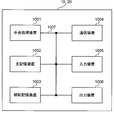
- FIG. 13 is a diagram illustrating an example of a hardware configuration of a radio base station and a user terminal according to an embodiment of the present invention.
- the wireless base station 10 and the user terminal 20 described above physically include a central processing unit (processor) 1001, a main storage device (memory) 1002, an auxiliary storage device 1003, a communication device 1004, an input device 1005, an output device 1006, You may comprise as a computer apparatus containing the bus
- the term “apparatus” can be read as a circuit, a device, a unit, or the like.
- Each function in the radio base station 10 and the user terminal 20 is performed by causing the central processing unit 1001 to perform computation by reading predetermined software (program) on hardware such as the central processing unit 1001 and the main storage device 1002. This is realized by controlling communication by the device 1004 and reading and / or writing of data in the main storage device 1002 and the auxiliary storage device 1003.
- the central processing unit 1001 controls the entire computer by operating an operating system, for example.
- the central processing unit 1001 may be configured by a processor (CPU: Central Processing Unit) including a control device, an arithmetic device, a register, an interface with peripheral devices, and the like.
- CPU Central Processing Unit
- the baseband signal processing unit 104 (204) and the call processing unit 105 described above may be realized by the central processing unit 1001.
- the central processing unit 1001 reads programs, software modules, and data from the auxiliary storage device 1003 and / or the communication device 1004 to the main storage device 1002, and executes various processes according to these.
- the program a program that causes a computer to execute at least a part of the operations described in the above embodiments is used.
- the control unit 401 of the user terminal 20 may be realized by a control program stored in the main storage device 1002 and operating on the central processing unit 1001, and may be realized similarly for other functional blocks.
- the main storage device (memory) 1002 is a computer-readable recording medium, and may be composed of at least one of ROM (Read Only Memory), EPROM (Erasable Programmable ROM), RAM (Random Access Memory), and the like, for example.
- the auxiliary storage device 1003 is a computer-readable recording medium, and may be composed of at least one of a flexible disk, a magneto-optical disk, a CD-ROM (Compact Disc ROM), a hard disk drive, and the like.
- the communication device 1004 is hardware (transmission / reception device) for performing communication between computers via a wired and / or wireless network, and is also referred to as a network device, a network controller, a network card, a communication module, or the like.
- a network device for example, the transmission / reception antenna 101 (201), the amplifier unit 102 (202), the transmission / reception unit 103 (203), the transmission path interface 106, and the like described above may be realized by the communication device 1004.
- the input device 1005 is an input device (for example, a keyboard, a mouse, etc.) that accepts external input.
- the output device 1006 is an output device (for example, a display, a speaker, etc.) that performs output to the outside.
- the input device 1005 and the output device 1006 may have an integrated configuration (for example, a touch panel).
- each device such as the central processing unit 1001 and the main storage device 1002 is connected by a bus 1007 for communicating information.
- the bus 1007 may be configured with a single bus or may be configured with different buses between apparatuses.
- the hardware configurations of the radio base station 10 and the user terminal 20 may be configured to include one or a plurality of the devices illustrated in the figure, or may be configured not to include some devices. .
- the radio base station 10 and the user terminal 20 may be configured to include hardware such as an ASIC (Application Specific Integrated Circuit), a PLD (Programmable Logic Device), and an FPGA (Field Programmable Gate Array). Thus, a part or all of each functional block may be realized.
- ASIC Application Specific Integrated Circuit
- PLD Process-Demand Generation
- FPGA Field Programmable Gate Array
- the channel and / or symbol may be a signal (signaling).
- the signal may be a message.
- a component carrier CC may be called a cell, a frequency carrier, a carrier frequency, or the like.
- information, parameters, and the like described in this specification may be represented by absolute values, may be represented by relative values from a predetermined value, or may be represented by other corresponding information.
- the radio resource may be indicated by a predetermined index.
- software, instructions, information, etc. may be transmitted / received via a transmission medium.
- software may use websites, servers, or other devices using wired technology (coaxial cable, fiber optic cable, twisted pair and digital subscriber line (DSL), etc.) and / or wireless technology (infrared, microwave, etc.) When transmitted from a remote source, these wired and / or wireless technologies are included within the definition of transmission media.
- notification of predetermined information is not limited to explicitly performed, but is performed implicitly (for example, by not performing notification of the predetermined information). May be.
- notification of information is not limited to the aspect / embodiment described in this specification, and may be performed by other methods.
- notification of information includes physical layer signaling (eg, DCI (Downlink Control Information), UCI (Uplink Control Information)), upper layer signaling (eg, RRC (Radio Resource Control) signaling, broadcast information (MIB (Master Information Block)). ), SIB (System Information Block)), MAC (Medium Access Control) signaling), other signals, or a combination thereof.
- RRC signaling may be referred to as an RRC message, and may be, for example, an RRC connection setup (RRCConnectionSetup) message, an RRC connection reconfiguration (RRCConnectionReconfiguration) message, or the like.
- Each aspect / embodiment described herein includes LTE (Long Term Evolution), LTE-A (LTE-Advanced), LTE-B (LTE-Beyond), SUPER 3G, IMT-Advanced, 4G (4th generation mobile). communication system), 5G (5th generation mobile communication system), FRA (Future Radio Access), New-RAT (Radio Access Technology), CDMA2000, UMB (Ultra Mobile Broadband), IEEE 802.11 (Wi-Fi (registered trademark)) ), IEEE 802.16 (WiMAX (registered trademark)), IEEE 802.20, UWB (Ultra-WideBand), Bluetooth (registered trademark), systems using other appropriate systems and / or extended based on these It may be applied to the next generation system.
- LTE Long Term Evolution
- LTE-A Long Term Evolution-Advanced
- LTE-B LTE-Beyond
- SUPER 3G IMT-Advanced
- communication system 5G (5th generation mobile communication system
Abstract
Description
先ず、第1の態様について図2を参照して説明する。図2は、上りリンク/下りリンク送信で用いられる複数のリソースプール(パターン)が配置された状態を示す図である。ここでは、同一セルに割り当てられた4つのリソースプール(リソースプール#1-#4)が配置されている。各リソースプールは、下り制御チャネル、下りリンク共有データチャネル、及び、上りリンク共有データチャネルの内の少なくとも1つのための無線リソースを割り当てることができる。 (First aspect)
First, a 1st aspect is demonstrated with reference to FIG. FIG. 2 is a diagram illustrating a state in which a plurality of resource pools (patterns) used for uplink / downlink transmission are arranged. Here, four resource pools (resource pools # 1- # 4) assigned to the same cell are arranged. Each resource pool can allocate radio resources for at least one of a downlink control channel, a downlink shared data channel, and an uplink shared data channel.
次に、第2の態様について図3及び図4を参照して説明する。第2の態様は、下りリンク送信に関するものであり、図3に示されるように、下りリンク送信で用いられる複数のリソースプール(パターン)が配置されている。ここでは、同一セルに割り当てられた3つのDLリソースプール(DLリソースプール#1-#3)が配置されている。各リソースプールは、下り制御チャネル(例えば、M-PDCCH)、及び、下りリンク共有データチャネルの内の少なくとも一方の無線リソースを割り当てることができる。 (Second aspect)
Next, a 2nd aspect is demonstrated with reference to FIG.3 and FIG.4. The second aspect relates to downlink transmission, and as shown in FIG. 3, a plurality of resource pools (patterns) used for downlink transmission are arranged. Here, three DL resource pools (DL resource pool # 1- # 3) allocated to the same cell are arranged. Each resource pool can be assigned a radio resource of at least one of a downlink control channel (for example, M-PDCCH) and a downlink shared data channel.
次に、第3の態様について図5を参照して説明する。第3の態様では、下りリンク送信に関し、特に、1PRB(Physical Resource Block)よりも狭い周波数帯域で1つのTBSに対してDLリソース割り当てを行うものである。言い換えると、1PRBよりも粒度(granularity)が小さい下りリンク送信をサポートする技術である。 (Third aspect)
Next, a 3rd aspect is demonstrated with reference to FIG. The third aspect relates to downlink transmission, and in particular, performs DL resource allocation for one TBS in a frequency band narrower than 1 PRB (Physical Resource Block). In other words, the technology supports downlink transmission with a granularity smaller than 1 PRB.
次に、第4の態様について図6を参照して説明する。第4の態様は、上りリンク送信に関するものであり、図6に示されるように、上りリンク送信で用いられる複数のリソースプール(パターン)が配置されている。ここでは、同一セルに割り当てられた4つのULリソースプール(ULリソースプール#1-#4)が配置されている。各リソースプールは、上りリンク共有データチャネル用の無線リソースを割り当てることができる。 (Fourth aspect)
Next, a 4th aspect is demonstrated with reference to FIG. The fourth aspect relates to uplink transmission. As shown in FIG. 6, a plurality of resource pools (patterns) used for uplink transmission are arranged. Here, four UL resource pools (UL resource pool # 1- # 4) allocated to the same cell are arranged. Each resource pool can allocate radio resources for the uplink shared data channel.
次に、第5の態様について図7を参照して説明する。第5の態様は、上りリンク送信に関し、特に、サブキャリア間隔を短くすることで時間方向に伸長したナローバンドサブキャリアを割り当てるものである。図7の中央部では、サブキャリア間隔15kHzを、2.5kHzに短くした場合のM-PRBが示されている。このため、ナローバンドサブキャリアは、時間方向に6倍されることになる。なお、図7の中央部を挟んだ左右には、LTEの1PRB(180kHz)が示されている。 (5th aspect)
Next, a fifth aspect will be described with reference to FIG. The fifth aspect relates to uplink transmission, and particularly assigns narrowband subcarriers extended in the time direction by shortening the subcarrier interval. In the center part of FIG. 7, M-PRB in the case where the
以下、本発明の一実施形態に係る無線通信システムの構成について説明する。この無線通信システムでは、上述した本発明の実施形態に係る無線通信方法が適用される。ここでは、狭帯域に使用帯域が制限されたユーザ端末としてNB-IoT UE(NB-IoT端末)を例示するが、これに限定されるものではない。 (Wireless communication system)
Hereinafter, the configuration of a wireless communication system according to an embodiment of the present invention will be described. In this wireless communication system, the above-described wireless communication method according to the embodiment of the present invention is applied. Here, an NB-IoT UE (NB-IoT terminal) is exemplified as a user terminal whose use band is limited to a narrow band, but the present invention is not limited to this.
図9は、本発明の一実施形態に係る無線基地局の全体構成の一例を示す図である。無線基地局10は、複数の送受信アンテナ101と、アンプ部102と、送受信部103と、ベースバンド信号処理部104と、呼処理部105と、伝送路インターフェース106と、を少なくとも備えている。 (Radio base station)
FIG. 9 is a diagram illustrating an example of the overall configuration of a radio base station according to an embodiment of the present invention. The
図11は、本発明の一実施形態に係るユーザ端末の全体構成の一例を示す図である。なお、ここでは詳細な説明を省略するが、通常のLTE端末がNB-IoT UEとしてふるまうように動作してもよい。ユーザ端末20は、送受信アンテナ201と、アンプ部202と、送受信部203と、ベースバンド信号処理部204と、アプリケーション部205と、を少なくとも備えている。また、ユーザ端末20は、送受信アンテナ201、アンプ部202、送受信部203などを複数備えてもよい。 (User terminal)
FIG. 11 is a diagram illustrating an example of the overall configuration of a user terminal according to an embodiment of the present invention. Although a detailed description is omitted here, a normal LTE terminal may behave as an NB-IoT UE. The
なお、上記実施形態の説明に用いたブロック図は、機能単位のブロックを示している。これらの機能ブロック(構成部)は、ハードウェア及び/又はソフトウェアの任意の組み合わせによって実現される。また、各機能ブロックの実現手段は特に限定されない。すなわち、各機能ブロックは、物理的に結合した1つの装置により実現されてもよいし、物理的に分離した2つ以上の装置を有線又は無線で接続し、これら複数の装置により実現されてもよい。 (Hardware configuration)
In addition, the block diagram used for description of the said embodiment has shown the block of the functional unit. These functional blocks (components) are realized by any combination of hardware and / or software. Further, the means for realizing each functional block is not particularly limited. That is, each functional block may be realized by one physically coupled device, or may be realized by two or more physically separated devices connected by wire or wirelessly and by a plurality of these devices. Good.
Claims (10)
- 複数の無線リソースで構成されるパターンに基づいて、無線基地局と信号の送信及び/又は受信を行う送受信部と、
ユーザ端末固有情報に基づいて、前記パターンを複数のパターンから決定する制御部と、を有するユーザ端末。 A transmission / reception unit that performs transmission and / or reception of signals with a radio base station, based on a pattern composed of a plurality of radio resources;
And a control unit that determines the pattern from a plurality of patterns based on the user terminal specific information. - 前記ユーザ端末固有情報は、ランダムアクセスチャネルのリソース及びユーザ端末ID(Identification)の内の少なくとも1つであることを特徴とする請求項1記載のユーザ端末。 The user terminal according to claim 1, wherein the user terminal specific information is at least one of a resource of a random access channel and a user terminal ID (Identification).
- 前記制御部は、セル固有情報に基づいて前記複数のパターンを特定することを特徴とする請求項1又は請求項2記載のユーザ端末。 The user terminal according to claim 1 or 2, wherein the control unit specifies the plurality of patterns based on cell specific information.
- 前記セル固有情報は、SIB(System Information Block)、セルID(Identification)及びサブフレーム番号の内の少なくとも1つであることを特徴とする請求項3記載のユーザ端末。 4. The user terminal according to claim 3, wherein the cell specific information is at least one of SIB (System Information Block), cell ID (Identification), and subframe number.
- 前記制御部は、パターンオフセット情報と前記セル固有情報とに基づいてパターンを決定することを特徴とする請求項1又は請求項2記載のユーザ端末。 3. The user terminal according to claim 1, wherein the control unit determines a pattern based on pattern offset information and the cell specific information.
- 前記送受信部は、前記パターンに対応する無線リソースで、下り制御チャネル、下り共有チャネル、及び、上り共有チャネルの内の少なくとも1つを用いて送信及び/又は受信を行うことを特徴とする請求項1から請求項5のいずれか1項に記載のユーザ端末。 The transmission / reception unit performs transmission and / or reception using at least one of a downlink control channel, a downlink shared channel, and an uplink shared channel with a radio resource corresponding to the pattern. The user terminal according to any one of claims 1 to 5.
- 前記パターンでは、無線リソースが、異なる狭帯域で周波数ホッピングされていることを特徴とする請求項1記載のユーザ端末。 The user terminal according to claim 1, wherein in the pattern, radio resources are frequency hopped in different narrow bands.
- 前記複数のパターンの数と前記異なる狭帯域の数とが等しいことを特徴とする請求項7記載のユーザ端末。 The user terminal according to claim 7, wherein the number of the plurality of patterns is equal to the number of the different narrow bands.
- 複数の無線リソースで構成されるパターンに基づいて、ユーザ端末と信号の送信及び/又は受信を行う送受信部と、
ユーザ端末固有情報に基づいて、前記パターンを複数のパターンから決定する制御部と、を有する無線基地局。 A transmission / reception unit that performs transmission and / or reception of signals with the user terminal based on a pattern composed of a plurality of radio resources;
And a control unit that determines the pattern from a plurality of patterns based on user terminal specific information. - 複数の無線リソースで構成されるパターンに基づいて、無線基地局と信号の送信及び/又は受信を行う工程と、
ユーザ端末固有情報に基づいて、前記パターンを複数のパターンから決定する工程と、を有する、ユーザ端末の無線通信方法。 A step of transmitting and / or receiving a signal with a radio base station based on a pattern composed of a plurality of radio resources;
And a step of determining the pattern from a plurality of patterns based on user terminal specific information.
Priority Applications (5)
| Application Number | Priority Date | Filing Date | Title |
|---|---|---|---|
| RU2018118565A RU2018118565A (en) | 2015-11-05 | 2016-11-04 | USER TERMINAL, BASIC RADIO STATION AND RADIO COMMUNICATION METHOD |
| EP16862189.4A EP3373672A4 (en) | 2015-11-05 | 2016-11-04 | User terminal, radio base station and radio communication method |
| JP2017549118A JPWO2017078129A1 (en) | 2015-11-05 | 2016-11-04 | User terminal, radio base station, and radio communication method |
| CN201680039961.0A CN107852698A (en) | 2015-11-05 | 2016-11-04 | User's set, wireless base station and wireless communications method |
| US15/579,614 US20180139725A1 (en) | 2015-11-05 | 2016-11-04 | User terminal, radio base station and radio communication method |
Applications Claiming Priority (2)
| Application Number | Priority Date | Filing Date | Title |
|---|---|---|---|
| JP2015218000 | 2015-11-05 | ||
| JP2015-218000 | 2015-11-05 |
Publications (1)
| Publication Number | Publication Date |
|---|---|
| WO2017078129A1 true WO2017078129A1 (en) | 2017-05-11 |
Family
ID=58662178
Family Applications (1)
| Application Number | Title | Priority Date | Filing Date |
|---|---|---|---|
| PCT/JP2016/082773 WO2017078129A1 (en) | 2015-11-05 | 2016-11-04 | User terminal, radio base station and radio communication method |
Country Status (6)
| Country | Link |
|---|---|
| US (1) | US20180139725A1 (en) |
| EP (1) | EP3373672A4 (en) |
| JP (1) | JPWO2017078129A1 (en) |
| CN (1) | CN107852698A (en) |
| RU (1) | RU2018118565A (en) |
| WO (1) | WO2017078129A1 (en) |
Cited By (2)
| Publication number | Priority date | Publication date | Assignee | Title |
|---|---|---|---|---|
| JP2019012932A (en) * | 2017-06-30 | 2019-01-24 | アンリツ株式会社 | Terminal test device and terminal test method |
| EP3698571A4 (en) * | 2017-11-06 | 2020-11-04 | Telefonaktiebolaget LM Ericsson (publ) | Network device and method for data transmission over common public radio interface |
Families Citing this family (6)
| Publication number | Priority date | Publication date | Assignee | Title |
|---|---|---|---|---|
| KR102565155B1 (en) * | 2016-01-27 | 2023-08-10 | 삼성전자주식회사 | Method and apparatus for measuring a channel in a wireless communication system |
| CN109565766B (en) * | 2016-06-21 | 2021-08-10 | 英特尔公司 | Method and apparatus for fast steering timing and resource allocation signaling for narrow band subchannels |
| EP3506701B1 (en) * | 2016-09-30 | 2022-01-12 | Kyocera Corporation | Mobile communication method |
| US10542543B2 (en) | 2016-11-02 | 2020-01-21 | Qualcomm Incorporated | Wireless communication between wideband ENB and narrowband UE |
| WO2019225657A1 (en) * | 2018-05-23 | 2019-11-28 | 株式会社Nttドコモ | User terminal and wireless communication method |
| CN112640547B (en) * | 2018-06-12 | 2024-02-13 | 株式会社Ntt都科摩 | Terminal, wireless communication method, base station and system |
Citations (1)
| Publication number | Priority date | Publication date | Assignee | Title |
|---|---|---|---|---|
| JP2011524658A (en) * | 2008-05-06 | 2011-09-01 | テレフオンアクチーボラゲット エル エム エリクソン(パブル) | Frequency hopping off setting for MUROS (MultipleUsersReusingOneSlot) |
Family Cites Families (3)
| Publication number | Priority date | Publication date | Assignee | Title |
|---|---|---|---|---|
| JP5114523B2 (en) * | 2010-04-05 | 2013-01-09 | 株式会社エヌ・ティ・ティ・ドコモ | Base station apparatus, mobile terminal apparatus and communication control method |
| EP2742628A4 (en) * | 2011-08-11 | 2015-05-20 | Nokia Corp | Pdsch assignment indication for fdd scell ack/nack transmission |
| US9973303B2 (en) * | 2013-12-20 | 2018-05-15 | Samsung Electronics Co., Ltd. | Determining timing for transmission or reception of signaling in a coverage enhanced operating mode |
-
2016
- 2016-11-04 US US15/579,614 patent/US20180139725A1/en not_active Abandoned
- 2016-11-04 WO PCT/JP2016/082773 patent/WO2017078129A1/en active Application Filing
- 2016-11-04 JP JP2017549118A patent/JPWO2017078129A1/en active Pending
- 2016-11-04 RU RU2018118565A patent/RU2018118565A/en not_active Application Discontinuation
- 2016-11-04 EP EP16862189.4A patent/EP3373672A4/en active Pending
- 2016-11-04 CN CN201680039961.0A patent/CN107852698A/en active Pending
Patent Citations (1)
| Publication number | Priority date | Publication date | Assignee | Title |
|---|---|---|---|---|
| JP2011524658A (en) * | 2008-05-06 | 2011-09-01 | テレフオンアクチーボラゲット エル エム エリクソン(パブル) | Frequency hopping off setting for MUROS (MultipleUsersReusingOneSlot) |
Non-Patent Citations (2)
| Title |
|---|
| NEC ET AL.: "WF on number of narrowbands for M-PDCCH and PDSCH frequency hopping", 3GPP TSG-RAN WG1#82BIS R1-156321, XP051044696, Retrieved from the Internet <URL:http://www.3gpp.org/ftp/tsg_ran/WG1_RL1/TSGR1_82b/Docs/R1-156321.zip> [retrieved on 20161226] * |
| See also references of EP3373672A4 * |
Cited By (3)
| Publication number | Priority date | Publication date | Assignee | Title |
|---|---|---|---|---|
| JP2019012932A (en) * | 2017-06-30 | 2019-01-24 | アンリツ株式会社 | Terminal test device and terminal test method |
| EP3698571A4 (en) * | 2017-11-06 | 2020-11-04 | Telefonaktiebolaget LM Ericsson (publ) | Network device and method for data transmission over common public radio interface |
| US11419132B2 (en) | 2017-11-06 | 2022-08-16 | Telefonaktiebolaget Lm Ericsson (Publ) | Network device and method for data transmission over common public radio interface |
Also Published As
| Publication number | Publication date |
|---|---|
| EP3373672A4 (en) | 2019-11-13 |
| CN107852698A (en) | 2018-03-27 |
| EP3373672A1 (en) | 2018-09-12 |
| US20180139725A1 (en) | 2018-05-17 |
| RU2018118565A (en) | 2019-12-05 |
| JPWO2017078129A1 (en) | 2018-08-23 |
Similar Documents
| Publication | Publication Date | Title |
|---|---|---|
| US10555280B2 (en) | User terminal, radio base station and radio communication method | |
| JP6310087B2 (en) | User terminal and wireless communication method | |
| JP6165276B2 (en) | User terminal, radio base station, and radio communication method | |
| WO2017078128A1 (en) | User terminal, radio base station and radio communication method | |
| JP6153575B2 (en) | User terminal, radio base station, and radio communication method | |
| JP6779212B2 (en) | User terminal, wireless base station and wireless communication method | |
| WO2017135345A1 (en) | User terminal, wireless base station, and wireless communication method | |
| WO2016072257A1 (en) | User terminal, wireless base station, and wireless communication method | |
| WO2017135419A1 (en) | User terminal, wireless base station, and wireless communication method | |
| WO2017078023A1 (en) | User terminal, radio base station and radio communication method | |
| WO2017078129A1 (en) | User terminal, radio base station and radio communication method | |
| JP2016219896A (en) | User terminal, radio base station, and radio communication method | |
| WO2017033841A1 (en) | User terminal, wireless base station, and wireless communication method | |
| WO2017026513A1 (en) | User terminal, wireless base station, wireless communication method, and wireless communication system | |
| WO2017150451A1 (en) | User terminal, wireless base station and wireless communication method | |
| WO2016182050A1 (en) | User terminal, wireless base station, wireless communication system, and wireless communication method | |
| JP6153574B2 (en) | User terminal, radio base station, and radio communication method | |
| JP6163181B2 (en) | User terminal, radio base station, and radio communication method | |
| JP6185096B2 (en) | User terminal, radio base station, and radio communication method | |
| WO2017026514A1 (en) | User terminal, wireless base station, wireless communication method, and wireless communication system | |
| JP2018046589A (en) | User terminal, radio base station and radio communication method |
Legal Events
| Date | Code | Title | Description |
|---|---|---|---|
| 121 | Ep: the epo has been informed by wipo that ep was designated in this application |
Ref document number: 16862189 Country of ref document: EP Kind code of ref document: A1 |
|
| WWE | Wipo information: entry into national phase |
Ref document number: 15579614 Country of ref document: US |
|
| ENP | Entry into the national phase |
Ref document number: 2017549118 Country of ref document: JP Kind code of ref document: A |
|
| NENP | Non-entry into the national phase |
Ref country code: DE |
|
| WWE | Wipo information: entry into national phase |
Ref document number: 2018118565 Country of ref document: RU Ref document number: 2016862189 Country of ref document: EP |