JP5114523B2 - Base station apparatus, mobile terminal apparatus and communication control method - Google Patents
Base station apparatus, mobile terminal apparatus and communication control method Download PDFInfo
- Publication number
- JP5114523B2 JP5114523B2 JP2010087390A JP2010087390A JP5114523B2 JP 5114523 B2 JP5114523 B2 JP 5114523B2 JP 2010087390 A JP2010087390 A JP 2010087390A JP 2010087390 A JP2010087390 A JP 2010087390A JP 5114523 B2 JP5114523 B2 JP 5114523B2
- Authority
- JP
- Japan
- Prior art keywords
- subframe
- instruction information
- control channel
- downlink control
- base station
- Prior art date
- Legal status (The legal status is an assumption and is not a legal conclusion. Google has not performed a legal analysis and makes no representation as to the accuracy of the status listed.)
- Expired - Fee Related
Links
Images


Classifications
-
- H—ELECTRICITY
- H04—ELECTRIC COMMUNICATION TECHNIQUE
- H04W—WIRELESS COMMUNICATION NETWORKS
- H04W16/00—Network planning, e.g. coverage or traffic planning tools; Network deployment, e.g. resource partitioning or cells structures
- H04W16/14—Spectrum sharing arrangements between different networks
- H04W16/16—Spectrum sharing arrangements between different networks for PBS [Private Base Station] arrangements
-
- H—ELECTRICITY
- H04—ELECTRIC COMMUNICATION TECHNIQUE
- H04W—WIRELESS COMMUNICATION NETWORKS
- H04W72/00—Local resource management
- H04W72/20—Control channels or signalling for resource management
- H04W72/23—Control channels or signalling for resource management in the downlink direction of a wireless link, i.e. towards a terminal
Landscapes
- Engineering & Computer Science (AREA)
- Computer Networks & Wireless Communication (AREA)
- Signal Processing (AREA)
- Mobile Radio Communication Systems (AREA)
Description
本発明は、次世代移動通信システムにおける基地局装置、移動端末装置及び通信制御方法に関する。 The present invention relates to a base station apparatus, a mobile terminal apparatus, and a communication control method in a next generation mobile communication system.
UMTS(Universal Mobile Telecommunications System)ネットワークにおいては、周波数利用効率の向上、データレートの向上を目的として、HSDPA(High Speed Downlink Packet Access)やHSUPA(High Speed Uplink Packet Access)を採用することにより、W-CDMA(Wideband Code Division Multiple Access)をベースとしたシステムの特徴を最大限に引き出すことが行われている。このUMTSネットワークについては、更なる高速データレート、低遅延などを目的としてロングタームエボリューション(LTE:Long Term Evolution)が検討されている(非特許文献1)。LTEでは、多重方式として、下り回線(下りリンク)にW−CDMAとは異なるOFDMA(Orthogonal Frequency Division Multiple Access)を用い、上り回線(上りリンク)にSC−FDMA(Single Carrier Frequency Division Multiple Access)を用いている。 In a UMTS (Universal Mobile Telecommunications System) network, HSDPA (High Speed Downlink Packet Access) and HSUPA (High Speed Uplink Packet Access) are adopted for the purpose of improving frequency utilization efficiency and data rate. A system based on CDMA (Wideband Code Division Multiple Access) is maximally extracted. For this UMTS network, Long Term Evolution (LTE) has been studied for the purpose of further high data rate and low delay (Non-Patent Document 1). In LTE, as a multiplexing method, OFDMA (Orthogonal Frequency Division Multiple Access) different from W-CDMA is used for the downlink (downlink), and SC-FDMA (Single Carrier Frequency Division Multiple Access) is used for the uplink (uplink). Used.
第3世代のシステムは、概して5MHzの固定帯域を用いて、下り回線で最大2Mbps程度の伝送レートを実現できる。一方、LTEのシステムでは、1.4MHz〜20MHzの可変帯域を用いて、下り回線で最大300Mbps及び上り回線で75Mbps程度の伝送レートを実現できる。また、UMTSネットワークにおいては、更なる広帯域化及び高速化を目的として、LTEの後継のシステムも検討されている(例えば、LTEアドバンスト(LTE−A))。LTE−A(LTE Release 10)では、従来のセルラ環境に加えてローカルエリア環境を重視したHeterogeneous network構成が検討されている。 The third generation system can realize a transmission rate of about 2 Mbps at the maximum on the downlink using a fixed band of 5 MHz in general. On the other hand, in the LTE system, a transmission rate of about 300 Mbps at the maximum in the downlink and about 75 Mbps in the uplink can be realized using a variable band of 1.4 MHz to 20 MHz. In addition, in the UMTS network, a successor system of LTE is also being studied for the purpose of further increasing the bandwidth and speed (for example, LTE Advanced (LTE-A)). In LTE-A (LTE Release 10), a heterogeneous network configuration in which a local area environment is emphasized in addition to a conventional cellular environment is being studied.
本発明はかかる点に鑑みてなされたものであり、Heterogeneous network内の干渉に適合した制御を行うことができ、次世代移動通信システムに対応する基地局装置、移動端末装置及び通信制御方法を提供することを目的とする。 The present invention has been made in view of the above points, and provides a base station apparatus, a mobile terminal apparatus, and a communication control method capable of performing control suitable for interference in a heterogeneous network and corresponding to a next-generation mobile communication system. The purpose is to do.
本発明の基地局装置は、大規模セルを有する第1のシステムと少なくとも一部の周波数帯が共用され、小規模セルをカバーし、複数の基本周波数ブロックからなるシステム帯域をもつ第2のシステムに配置された基地局装置であり、基本周波数ブロックの制御チャネルで同一の基本周波数ブロック以外にユーザデータが割り当てられる他の基本周波数ブロックを指示する他、前記下り制御チャネルで同一のサブフレーム以外にユーザデータが割り当てられる他のサブフレームを指示する指示情報を生成する指示情報生成部と、前記指示情報を含む送信フレームを生成する送信フレーム生成部とを備えたことを特徴とする。 The base station apparatus of the present invention shares at least a part of a frequency band with a first system having a large-scale cell, covers a small-sized cell, and has a system band composed of a plurality of basic frequency blocks. In addition to indicating other basic frequency blocks to which user data is assigned in addition to the same basic frequency block in the control channel of the basic frequency block, in addition to indicating the same subframe in the downlink control channel An instruction information generation unit that generates instruction information indicating other subframes to which user data is allocated and a transmission frame generation unit that generates a transmission frame including the instruction information are provided.
本発明によれば、下り制御チャネルで同一サブフレーム以外に、指示情報に指示された他のサブフレームに対してユーザデータを割り当てることができる。よって、指示情報により第1のシステムにより干渉を受ける制御チャネルのサブフレームを指示することで、干渉を受けないサブフレームの制御チャネルで、干渉を受けるサブフレームのユーザデータを割り当てることができる。また、制御チャネルで同一の基本周波数ブロック以外にユーザデータが割り当てられる他の基本周波数ブロックを指示する指示情報を用いて、同一のサブフレーム以外にユーザデータが割り当てられる他のサブフレームを指示するため、簡易な制御構成とすることができる。 According to the present invention, it is possible to allocate user data to other subframes indicated in the indication information in addition to the same subframe on the downlink control channel. Therefore, by indicating the subframe of the control channel that is subject to interference by the first system using the indication information, the user data of the subframe that is subject to interference can be allocated by the control channel of the subframe that is not subject to interference. In addition, in order to indicate other subframes to which user data is allocated in addition to the same subframe, using the instruction information indicating other basic frequency blocks to which user data is allocated in addition to the same basic frequency block in the control channel Thus, a simple control configuration can be obtained.
図1は、下りリンクで移動通信が行われる際の周波数使用状態を説明するための図である。なお、以下の説明では基本周波数ブロックをコンポーネントキャリアとして説明する。図1に示す例は、複数のコンポーネントキャリアで構成される相対的に広い第1システム帯域を持つ第1通信システムであるLTE−Aシステムと、相対的に狭い(ここでは、一つのコンポーネントキャリアで構成される)第2システム帯域を持つ第2通信システムであるLTEシステムが併存する場合の周波数使用状態である。LTE−Aシステムにおいては、例えば、100MHz以下の可変のシステム帯域幅で無線通信し、LTEシステムにおいては、20MHz以下の可変のシステム帯域幅で無線通信する。LTE−Aシステムのシステム帯域は、LTEシステムのシステム帯域を一単位とする少なくとも一つの基本周波数領域(コンポーネントキャリア:CC)となっている。このように複数の基本周波数領域を一体として広帯域化することをキャリアアグリゲーションという。 FIG. 1 is a diagram for explaining a frequency usage state when mobile communication is performed in the downlink. In the following description, the fundamental frequency block is described as a component carrier. The example shown in FIG. 1 is an LTE-A system, which is a first communication system having a relatively wide first system band composed of a plurality of component carriers, and a relatively narrow (here, one component carrier). This is a frequency usage state when an LTE system, which is a second communication system having a second system band (which is configured) coexists. In the LTE-A system, for example, wireless communication is performed with a variable system bandwidth of 100 MHz or less, and in the LTE system, wireless communication is performed with a variable system bandwidth of 20 MHz or less. The system band of the LTE-A system is at least one basic frequency region (component carrier: CC) with the system band of the LTE system as one unit. In this way, widening a band by integrating a plurality of fundamental frequency regions is called carrier aggregation.
例えば、図1においては、LTE−Aシステムのシステム帯域は、LTEシステムのシステム帯域(ベース帯域:20MHz)を一つのコンポーネントキャリアとする5つのコンポーネントキャリアの帯域を含むシステム帯域(20MHz×5=100MHz)となっている。図1においては、移動端末装置UE(User Equipment)#1は、LTE−Aシステム対応(LTEシステムにも対応)の移動端末装置であり、100MHzのシステム帯域を持ち、UE#2は、LTE−Aシステム対応(LTEシステムにも対応)の移動端末装置であり、40MHz(20MHz×2=40MHz)のシステム帯域を持ち、UE#3は、LTEシステム対応(LTE−Aシステムには対応せず)の移動端末装置であり、20MHz(ベース帯域)のシステム帯域を持つ。 For example, in FIG. 1, the system band of the LTE-A system is a system band (20 MHz × 5 = 100 MHz) including five component carrier bands, where the LTE system band (base band: 20 MHz) is one component carrier. ). In FIG. 1, mobile terminal apparatus UE (User Equipment) # 1 is a mobile terminal apparatus compatible with the LTE-A system (also supports the LTE system), has a system band of 100 MHz, and UE # 2 It is a mobile terminal device compatible with the A system (also supporting the LTE system), has a system band of 40 MHz (20 MHz × 2 = 40 MHz), and UE # 3 is compatible with the LTE system (not compatible with the LTE-A system). Mobile terminal apparatus having a system band of 20 MHz (base band).
ところで、LTE−Aシステムでは、ローカルエリア環境を重視したHeterogeneous network(以下、HetNetとする)構成が検討されている。HetNetとは、図2に示すように、従来のマクロセルC2(大規模セル)に加え、ピコセルC1やフェムトセル等(小規模セル)の様々な形態のセルをオーバレイした階層型ネットワークである。このHetNetにおいては、相対的に広いエリアをカバーするマクロセルC2の基地局装置B2は、相対的に狭いエリアをカバーするピコセルC1の基地局装置B1よりも下り送信電力が大きく設定されている。 By the way, in the LTE-A system, a heterogeneous network (hereinafter referred to as “HetNet”) configuration focusing on the local area environment is being studied. As shown in FIG. 2, HetNet is a hierarchical network in which various types of cells such as a pico cell C1 and a femto cell (small cell) are overlaid in addition to a conventional macro cell C2 (large cell). In this HetNet, the base station apparatus B2 of the macro cell C2 that covers a relatively large area has a larger downlink transmission power than the base station apparatus B1 of the pico cell C1 that covers a relatively narrow area.
したがって、マクロセルC2とピコセルC1とが接近した周波数帯域で運用されると、図3に示すように、ピコセルC1の基地局装置B1からの無線フレームは、マクロセルC2の基地局装置B2からの無線フレームによって大きな干渉を受けるという問題があった。このため、ピコセルC1は、このマクロセルC2からの大きな干渉によりカバレッジが狭められていた。また、特にサブフレームの先頭に配置された下り制御チャネル(PDCCH:Physical Downlink Control Channel)は、下りデータチャネル(PDSCH:Physical Downlink Shared Channel)と異なり基本的に再送されないため、マクロセルC2からの干渉により大きな影響が与えられていた。さらに、サブフレーム内のBで示される、報知チャネル(PBCH:Physical Broadcast Channel)やセルサーチ用の同期信号(PSS:Primary Synchronization Signal, SSS:Secondary Synchronization Signal)も同様に、基本的に再送されないためマクロセルC2からの干渉により大きな影響が与えられていた。 Therefore, when the macro cell C2 and the pico cell C1 are operated in a close frequency band, as shown in FIG. 3, the radio frame from the base station apparatus B1 of the pico cell C1 is the radio frame from the base station apparatus B2 of the macro cell C2. There was a problem of receiving large interference. For this reason, the coverage of the pico cell C1 is narrowed due to the large interference from the macro cell C2. In particular, a downlink control channel (PDCCH: Physical Downlink Control Channel) arranged at the head of a subframe is not basically retransmitted unlike a downlink data channel (PDSCH: Physical Downlink Shared Channel), and therefore, due to interference from the macro cell C2. It had a great influence. Furthermore, the broadcast channel (PBCH: Physical Broadcast Channel) and the cell search synchronization signal (PSS: Primary Synchronization Signal, SSS: Secondary Synchronization Signal) indicated by B in the subframe are basically not retransmitted. The interference from the macro cell C2 is greatly affected.
これらの問題を解決するために、図4に示すように、MBSFN(Multimedia Broadcast multicast service Single Frequency Network)サブフレームとサブフレームシフトとを用いる方法が考えられる。MBSFNサブフレームとは、LTEシステムで仕様化されており、制御チャネル以外をブランク期間にすることが可能なサブフレームである。この構成によれば、マクロセルC2及びピコセルC1の無線フレームが時間軸方向にサブフレームシフトされることで下り制御チャネルのオーバラップが解消される。また、MBSFNサブフレームによってマクロセルC2の無線フレームに部分的にブランク期間が設けられ、ピコセルC1の破線で囲まれたサブフレームの下り制御チャネル、報知チャネル、同期信号の干渉が抑えられる。この結果、ピコセルC1の下り制御チャネル、報知チャネル、同期信号のカバレッジが保障される。また、ピコセルC1の破線で囲まれたサブフレームの下りデータチャネルも、マクロセルC2の無線フレームのブランク期間により干渉が減るため、データレートの改善が見込まれる。 In order to solve these problems, as shown in FIG. 4, a method using MBSFN (Multimedia Broadcast Multicast Service Single Frequency Network) subframe and subframe shift is conceivable. The MBSFN subframe is a subframe that is specified in the LTE system and can make a blank period other than the control channel. According to this configuration, the radio frames of the macro cell C2 and the pico cell C1 are subframe shifted in the time axis direction, thereby eliminating the downlink control channel overlap. Also, a blank period is partially provided in the radio frame of the macro cell C2 by the MBSFN subframe, and interference of the downlink control channel, broadcast channel, and synchronization signal in the subframe surrounded by the broken line of the picocell C1 is suppressed. As a result, the coverage of the downlink control channel, broadcast channel, and synchronization signal of the pico cell C1 is ensured. Further, the downlink data channel of the subframe surrounded by the broken line of the pico cell C1 is also expected to improve the data rate because the interference is reduced by the blank period of the radio frame of the macro cell C2.
しかしながら、上記した方法では、ピコセルC1の破線で囲まれたサブフレーム以外のサブフレームでは、制御チャネルがマクロセルC2の無線フレームに干渉を受けている。下りの無線フレームの制御チャネルは、同一サブフレーム内のデータチャネル(PDSCH)のスケジューリング情報等の伝送、すなわち、同一サブフレーム内のユーザデータの割り当てに用いられている。このため、下り制御チャネルが干渉される場合には、同一サブフレーム内のユーザデータの割り当て(スケジューリング)ができないという問題があった。 However, in the above-described method, the control channel is interfered with the radio frame of the macro cell C2 in subframes other than the subframe surrounded by the broken line of the picocell C1. The control channel of the downlink radio frame is used for transmission of scheduling information of the data channel (PDSCH) in the same subframe, that is, for allocation of user data in the same subframe. For this reason, when the downlink control channel is interfered, there is a problem that user data cannot be allocated (scheduled) in the same subframe.
そこで、本発明者らは、この問題点を解決するために、本発明をするに至った。すなわち、本発明の骨子は、ピコセルの制御チャネルに対し、マクロセルの基地局装置からの干渉を部分的に抑制して、この干渉が抑制された一部の制御チャネルを用いて同一サブフレーム以外のサブフレームに対するユーザデータの割り当てを可能とすることである。 Therefore, the present inventors have come up with the present invention in order to solve this problem. That is, the essence of the present invention is that the interference from the macro cell base station apparatus is partially suppressed with respect to the control channel of the pico cell, and a part other than the same subframe is used by using some control channels in which the interference is suppressed. It is possible to assign user data to subframes.
以下、本発明の実施の形態について、添付図面を参照して詳細に説明する。図5は、ユーザデータの割り当て方法の一例を示す説明図である。 Hereinafter, embodiments of the present invention will be described in detail with reference to the accompanying drawings. FIG. 5 is an explanatory diagram illustrating an example of a user data allocation method.
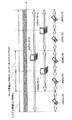
図5に示すように、マクロセルC2の下り無線フレームは、サブフレーム#0−#9の10サブフレームで構成されており、各サブフレームの先頭側のOFDMシンボルに制御チャネル(PDCCH)が多重されている。また、マクロセルC2の下り無線フレームは、上記したMBSFNサブフレームを有し、サブフレーム#0、#4、#5、#9以外のサブフレームの制御チャネル以外にブランク期間が設けられている。サブフレーム#0、#5には、報知チャネル(PBCH)やセルサーチ用の同期信号(PSS,SSS)が多重されている。
As shown in FIG. 5, the downlink radio frame of the macro cell C2 is composed of 10 subframes of
一方、ピコセルC1の下り無線フレームは、マクロセルC2の下り無線フレームと同様な無線フレーム構成を有するが、サブフレームにブランク期間が設けられていない。また、ピコセルC1の下り無線フレームは、マクロセルC2の無線フレームに対して時間軸方向に相対的にサブフレームシフトされている。これにより、ピコセルC1の下り無線フレーム内の一部の制御チャネルや、報知チャネル、同期信号等が、マクロセルC2の下り無線フレームのブランク期間に合わされて、マクロセルC2からの干渉が抑えられている。本実施の形態においては、干渉が抑えられた一部の制御チャネルは、干渉の抑えられていない制御チャネルに代わって、データチャネル(PDSCH)のスケジューリング情報を伝送する。 On the other hand, the downlink radio frame of the pico cell C1 has the same radio frame configuration as the downlink radio frame of the macro cell C2, but no blank period is provided in the subframe. Also, the downlink radio frame of the pico cell C1 is subframe shifted relative to the radio frame of the macro cell C2 in the time axis direction. Thereby, some control channels, broadcast channels, synchronization signals, and the like in the downlink radio frame of the pico cell C1 are matched with the blank period of the downlink radio frame of the macro cell C2, and interference from the macro cell C2 is suppressed. In the present embodiment, some control channels with reduced interference transmit data channel (PDSCH) scheduling information instead of control channels with reduced interference.
例えば、ピコセルC1の下り無線フレームにおいて、サブフレーム#1の制御チャネルは、マクロセルC2の下り無線フレームのブランク期間に対応しており、マクロセルC2からの干渉を受けていない。このサブフレーム#1の制御チャネルは、同一サブフレームのデータチャネルのみならず、マクロセルC2からの干渉を受けた隣接サブフレーム#2の制御チャネルに代わって、サブフレーム#2のデータチャネルのスケジューリング情報を伝送する。このように、ピコセルC1の無線フレームにおいては、制御チャネルが、同一サブフレームのみならず隣接サブフレーム対するユーザデータの割り当てを行っている。
For example, in the downlink radio frame of the pico cell C1, the control channel of
なお、制御チャネルは、隣接サブフレームだけでなく、後続サブフレームに対するユーザデータの割り当てを行うことも可能である。例えば、ピコセルC1の下り無線フレームにおいて、サブフレーム#4の制御チャネルは、マクロセルC2の無線フレームのブランク期間に対応しており、マクロセルC2からの干渉を受けていない。この場合、サブフレーム#4の制御チャネルは、同一サブフレームのデータチャネルのみならず、マクロセルC2からの干渉を受けた3サブフレーム後のサブフレーム#7の制御チャネルに代わって、サブフレーム#7のデータチャネルのスケジューリング情報を伝送する。
Note that the control channel can assign user data not only to adjacent subframes but also to subsequent subframes. For example, in the downlink radio frame of the pico cell C1, the control channel of
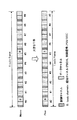
このような下り制御チャネルによる、複数のサブフレームに対するユーザデータの割り当ては、キャリアインディケータ(CI:Carrier indicator)を用いて行われる。ここで、キャリアインディケータについて簡単に説明する。LTE−Aでは、複数のコンポーネントキャリアにより広帯域化され、クロスキャリアスケジューリング(Cross-carrier scheduling)が検討されている。クロスキャリアスケジューリングとは、図6に示すように、他セルから強い干渉を受けたコンポーネントキャリア(CC#2)の代わりに、干渉の影響の少ない他のコンポーネントーキャリア(CC#1)の下り制御チャネルを用いるものである。 Allocation of user data to a plurality of subframes using such a downlink control channel is performed using a carrier indicator (CI). Here, the carrier indicator will be briefly described. In LTE-A, the bandwidth is increased by a plurality of component carriers, and cross-carrier scheduling is being studied. As shown in FIG. 6, cross-carrier scheduling is downlink control of another component carrier (CC # 1) that is less affected by interference instead of the component carrier (CC # 2) that has received strong interference from another cell. A channel is used.
この場合、下り制御チャネルで伝送される下り制御情報(DCI:Downlink Control Information)には、指示情報としての3ビットのキャリアインディケータが付加されている。キャリアインディケータは、下り制御チャネルで同一のコンポーネントキャリア以外にユーザデータが割り当てられる他のコンポーネントキャリアを指示可能とするものである。このキャリアインディケータを用いることで、移動端末装置では、下り制御情報が単一のコンポーネントキャリアの下り制御チャネルで受信され、下りユーザデータがそれぞれのコンポーネントキャリアの下りデータチャネルで受信される。本実施の形態では、このキャリアインディケータの解釈を変えて、制御チャネルで同一のサブフレームだけでなく、後続サブフレームに対するユーザデータの割り当てを可能としている。 In this case, a 3-bit carrier indicator serving as instruction information is added to downlink control information (DCI) transmitted on the downlink control channel. The carrier indicator can indicate other component carriers to which user data is allocated in addition to the same component carrier in the downlink control channel. By using this carrier indicator, in the mobile terminal apparatus, downlink control information is received on the downlink control channel of a single component carrier, and downlink user data is received on the downlink data channel of each component carrier. In the present embodiment, the interpretation of the carrier indicator is changed, and the user data can be assigned not only to the same subframe but also to the subsequent subframe on the control channel.
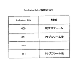
図7及び図8を参照して、キャリアインディケータの解釈方法について説明する。図7は、キャリアインディケータの第1の解釈方法の説明図である。図8は、キャリアインディケータの第2の解釈方法の説明図である。なお、以下の説明においては、キャリアインディケータを3ビットとして説明するが、この構成に限定されるものではない。キャリアインディケータのビット数は、コンポーネントキャリア数やサブフレーム数に応じて変更することも可能である。 With reference to FIG.7 and FIG.8, the interpretation method of a carrier indicator is demonstrated. FIG. 7 is an explanatory diagram of a first interpretation method of the carrier indicator. FIG. 8 is an explanatory diagram of a second interpretation method of the carrier indicator. In the following description, the carrier indicator is described as 3 bits, but is not limited to this configuration. The number of bits of the carrier indicator can be changed according to the number of component carriers and the number of subframes.
図7に示すように、第1の解釈方法は、キャリアインディケータを、下り制御チャネルのサブフレームから当該制御チャネルでユーザデータが割り当てられる他のサブフレームまでのサブフレーム数として解釈させる。例えば、キャリアインディケータは、「000」の場合に現サブフレームに対するユーザデータの割り当てとして解釈され、「001」の場合に1サブフレーム後の隣接サブフレームに対するユーザデータの割り当てとして解釈される。したがって、下り制御情報に付加されたキャリアインディケータにより、制御チャネルで同一のサブフレーム以外の他のサブフレームに対するユーザデータの割り当てを可能にしている。なお、この場合、キャリアインディケータがキャリア指示用か、又はサブフレーム指示用かを判別するための情報を別途通知するようにしてもよい。 As shown in FIG. 7, in the first interpretation method, the carrier indicator is interpreted as the number of subframes from the subframe of the downlink control channel to another subframe to which user data is assigned on the control channel. For example, the carrier indicator is interpreted as an assignment of user data to the current subframe when “000”, and as an assignment of user data to an adjacent subframe after one subframe when “001”. Therefore, the carrier indicator added to the downlink control information enables user data to be allocated to other subframes other than the same subframe on the control channel. In this case, information for determining whether the carrier indicator is for carrier instruction or subframe instruction may be separately notified.
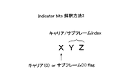
図8に示すように、第2の解釈方法は、キャリアインディケータの第1ビットと第2、第3ビットとが別々に解釈される。第1ビットは、キャリアインディケータがキャリア指示用か、又はサブフレーム指示用かを判別するための判別ビットとして解釈される。例えば、キャリアインディケータは、第1ビットが「0」の場合、キャリア指示用として、上記したクロスキャリアスケジューリングに用いられる。一方、キャリアインディケータは、第1ビットが「1」の場合、サブフレーム指示用として、制御チャネルで同一サブフレーム以外の他のサブフレームに対するユーザデータのスケジューリングに用いられる。 As shown in FIG. 8, in the second interpretation method, the first bit and the second and third bits of the carrier indicator are interpreted separately. The first bit is interpreted as a determination bit for determining whether the carrier indicator is for carrier instruction or subframe instruction. For example, when the first bit is “0”, the carrier indicator is used for the above-described cross carrier scheduling for carrier indication. On the other hand, when the first bit is “1”, the carrier indicator is used for scheduling user data for other subframes other than the same subframe on the control channel for subframe indication.
第2、第3ビットは、第1ビットの判別結果に応じて、各コンポーネントキャリアに対応したキャリアインデックス(基本周波数ブロックインデックス)、又は各サブフレームに対応したサブフレームインデックスを特定するためのインデックスビットとして解釈される。なお、各コンポーネントキャリアに対応したキャリアインデックスとは、各コンポーネントキャリアに割り当てられた固定的な情報でもよいし、基準となるコンポーネントキャリアに対する相対的な情報でもよい。また、各サブフレームに対応したサブフレームインデックスとは、各サブフレームに割り当てられた固定的な情報でもよいし、基準となるサブフレームに対する相対的な情報でもよい。よって、サブフレームインデックスは、第1の解釈方法と同様に、下り制御チャネルのサブフレームから当該制御チャネルでユーザデータが割り当てられる他のサブフレームまでのサブフレーム数として解釈させることも可能である。 The second and third bits are index bits for specifying a carrier index (basic frequency block index) corresponding to each component carrier or a subframe index corresponding to each subframe according to the determination result of the first bit. Is interpreted as The carrier index corresponding to each component carrier may be fixed information assigned to each component carrier, or may be relative information with respect to a reference component carrier. Further, the subframe index corresponding to each subframe may be fixed information assigned to each subframe, or may be information relative to a reference subframe. Therefore, the subframe index can be interpreted as the number of subframes from the subframe of the downlink control channel to other subframes to which user data is allocated on the control channel, as in the first interpretation method.
第2、第3ビットは、キャリアインディケータがキャリア指示用と判別される場合、コンポーネントキャリアのキャリアインデックスを示す。一方、第2、第3ビットは、キャリアインディケータがサブフレーム指示用と判別される場合、サブフレームのサブフレームインデックスを示す。このように、第1ビットと第2、第3ビットとを組み合わせて、キャリアインディケータをキャリア指示用とサブフレーム指示用とで使い分けることが可能となる。 The second and third bits indicate the carrier index of the component carrier when the carrier indicator is determined to be for carrier indication. On the other hand, the second and third bits indicate the subframe index of the subframe when the carrier indicator is determined to be for subframe indication. In this way, by combining the first bit with the second and third bits, it is possible to use the carrier indicator separately for carrier instruction and subframe instruction.
このキャリアインディケータは、下り制御情報毎に付加される。これにより、単一の制御チャネルにおいて、複数のサブフレームに対する下り制御情報を区別して伝送することが可能となる。なお、キャリアインディケータは、上記した第1、第2の解釈方法に限定されるものではなく、下り制御チャネルで同一のサブフレーム以外にユーザデータが割り当てられる他のサブフレームが指示される構成であれば、どのような解釈方法が適用されてもよい。 This carrier indicator is added for each downlink control information. This makes it possible to transmit downlink control information for a plurality of subframes separately in a single control channel. The carrier indicator is not limited to the first and second interpretation methods described above, and any other subframe to which user data is assigned in addition to the same subframe in the downlink control channel may be indicated. Any interpretation method may be applied.
なお、移動端末装置には、キャリアインディケータを第1の解釈方法、第2の解釈方法で解釈させるための情報が事前に通知される構成としてもよい。この場合、基地局装置において、キャリアインディケータとサブフレーム及びコンポーネントキャリアとの対応関係を変更できる。また、移動端末装置には、キャリアインディケータとサブフレーム及びコンポーネントキャリアとの対応関係が固定的に記憶される構成としてもよい。 Note that the mobile terminal device may be configured to be notified in advance of information for causing the carrier indicator to be interpreted by the first interpretation method and the second interpretation method. In this case, in the base station apparatus, the correspondence relationship between the carrier indicator, the subframe, and the component carrier can be changed. Further, the mobile terminal device may be configured to store the correspondence relationship between the carrier indicator, the subframe, and the component carrier in a fixed manner.
ところで、図14に示すように、マクロセル側の基地局装置においては、マクロセルC2からピコセルC1に対する干渉を抑えるため、マクロセルC2の下り制御チャネルをオフにする状況が考えられる。この場合、上記したキャリアインディケータを用いて、オフに設定されていない下り制御チャネルにより、オフに設定された下り制御チャネルのサブフレームに対しユーザデータの割り当てることもできる。なお、下り制御チャネルのオンとは、下り制御情報を伝送可能な状態を示し、下り制御チャネルのオフとは、下り制御情報を伝送できない状態を示す。 By the way, as shown in FIG. 14, in the base station apparatus on the macro cell side, in order to suppress interference from the macro cell C2 to the pico cell C1, it is conceivable that the downlink control channel of the macro cell C2 is turned off. In this case, it is also possible to allocate user data to the subframe of the downlink control channel set to off by the downlink control channel not set to off, using the carrier indicator described above. The downlink control channel on indicates a state in which downlink control information can be transmitted, and the downlink control channel off indicates a state in which downlink control information cannot be transmitted.
例えば、マクロセルC2の下り無線フレームにおいて、サブフレーム#2の制御チャネルはオフに設定されており、ピコセルC1の下り無線フレームに対する干渉を抑えている。マクロセルC2のサブフレーム#1の制御チャネルは、このサブフレーム#2の制御チャネルに代わって、サブフレーム#2のデータチャネルのスケジューリング情報を伝送する。このように、マクロセルC2の無線フレームにおいては、制御チャネルが、同一サブフレームのみならず後続サブフレーム対するユーザデータの割り当てが可能に構成されている。
For example, in the downlink radio frame of the macro cell C2, the control channel of the
図15を参照して、マクロセル側の基地局装置でユーザデータの割り当て制御する際のキャリアインディケータの解釈方法について説明する。図15は、マクロセルにおけるキャリアインディケータの解釈方法の一例を示す説明図である。なお、以下の説明においては、キャリアインディケータを3ビットとして説明するが、この構成に限定されるものではない。キャリアインディケータのビット数は、コンポーネントキャリア数やサブフレーム数に応じて変更することも可能である。 With reference to FIG. 15, the interpretation method of the carrier indicator at the time of controlling the allocation of user data in the base station apparatus on the macro cell side will be described. FIG. 15 is an explanatory diagram showing an example of a method for interpreting a carrier indicator in a macro cell. In the following description, the carrier indicator is described as 3 bits, but is not limited to this configuration. The number of bits of the carrier indicator can be changed according to the number of component carriers and the number of subframes.
図15に示すように、キャリアインディケータは、キャリアインデックスとサブフレームインデックスとに関連付けられている。図14に示す例では、マクロセルC2において制御チャネルがオフにされているのは、キャリアインディケータは、サブフレーム#2、#7、#8なので、現サブフレームとサブフレーム#2、#7、#8に対して指示可能に構成されている。また、キャリアインディケータは、サブフレームと共にコンポーネントキャリアCC#1、CC#2を指示可能に構成されている。
As shown in FIG. 15, the carrier indicator is associated with a carrier index and a subframe index. In the example shown in FIG. 14, the control channel is turned off in the macro cell C2 because the carrier indicators are
なお、ここでいうキャリアインデックスとは、各コンポーネントキャリアに割り当てられた固定的な情報でもよいし、基準となるコンポーネントキャリアに対する相対的な情報でもよい。また、サブフレームインデックスとは、各サブフレームに割り当てられた固定的な情報でもよいし、基準となるサブフレームに対する相対的な情報でもよい。よって、サブフレームインデックスは、下り制御チャネルのサブフレームから当該制御チャネルでユーザデータが割り当てられる他のサブフレームまでのサブフレーム数として解釈させることも可能である。 The carrier index here may be fixed information assigned to each component carrier, or may be relative information with respect to a reference component carrier. The subframe index may be fixed information assigned to each subframe, or may be relative information with respect to a reference subframe. Therefore, the subframe index can be interpreted as the number of subframes from the subframe of the downlink control channel to other subframes to which user data is assigned by the control channel.
例えば、キャリアインディケータは、「000」の場合に、コンポーネントキャリアCC#1の現サブフレームに対するユーザデータの割り当てとして解釈される。また、キャリアインディケータは、「101」の場合に、コンポーネントキャリアCC#2のサブフレーム#2に対するユーザデータの割り当てとして解釈される。したがって、下り制御情報に付加されたキャリアインディケータにより、制御チャネルで同一のサブフレーム以外の他のサブフレームに対するユーザデータの割り当てを可能にしている。
For example, in the case of “000”, the carrier indicator is interpreted as user data allocation to the current subframe of component
なお、移動端末装置には、キャリアインディケータとサブフレーム及びコンポーネントキャリアとの対応関係を示す情報が事前に通知される構成としてもよい。この場合、基地局装置において、キャリアインディケータとサブフレーム及びコンポーネントキャリアとの対応関係を変更できる。また、移動端末装置には、キャリアインディケータとサブフレーム及びコンポーネントキャリアとの対応関係が固定的に記憶される構成としてもよい。 Note that the mobile terminal device may be configured to be notified in advance of information indicating the correspondence between the carrier indicator, the subframe, and the component carrier. In this case, in the base station apparatus, the correspondence relationship between the carrier indicator, the subframe, and the component carrier can be changed. Further, the mobile terminal device may be configured to store the correspondence relationship between the carrier indicator, the subframe, and the component carrier in a fixed manner.
ここで、本発明の実施例に係る無線通信システムについて詳細に説明する。図9は、本実施例に係る無線通信システムのシステム構成の説明図である。なお、図9に示す無線通信システムは、例えば、LTEシステム或いは、SUPER 3Gが包含されるシステムである。また、この無線通信システムは、IMT−Advancedと呼ばれても良いし、4Gと呼ばれても良い。 Here, the wireless communication system according to the embodiment of the present invention will be described in detail. FIG. 9 is an explanatory diagram of the system configuration of the wireless communication system according to the present embodiment. Note that the radio communication system illustrated in FIG. 9 is a system including, for example, an LTE system or SUPER 3G. Moreover, this radio | wireless communications system may be called IMT-Advanced, and may be called 4G.
図9に示すように、無線通信システム1は、HetNetであり、マクロセルC2を有する第1のシステムと、ピコセルC1を有する第2のシステムとにより、階層型ネットワークが構築されている。第1のシステムは、マクロセルC2をカバーする基地局装置40と、この基地局装置40と通信する移動端末装置30(1つのみ図示)とを含んで構成されている。第2のシステムは、ピコセルC1をカバーする基地局装置20と、この基地局装置20と通信する移動端末装置10(1つのみ図示)とを含んで構成されている。基地局装置20、40は、それぞれ図示しない上位局装置に接続され、上位局装置を介してコアネットワーク50と接続される。なお、説明の便宜上、基地局装置20、40と無線通信するのは移動端末装置であるものとして説明するが、より一般的には移動端末装置も固定端末装置も含むユーザ装置(UE:User Equipment)でよい。
As shown in FIG. 9, the
無線通信システム1においては、無線アクセス方式として、下りリンクについてはOFDMA(直交周波数分割多元接続)が、上りリンクについてはSC−FDMA(シングルキャリア−周波数分割多元接続)が適用される。OFDMAは、周波数帯域を複数の狭い周波数帯域(サブキャリア)に分割し、各サブキャリアにデータをマッピングして通信を行うマルチキャリア伝送方式である。SC−FDMAは、システム帯域を端末毎に1つ又は連続したリソースブロックからなる帯域に分割し、複数の端末が互いに異なる帯域を用いることで、端末間の干渉を低減するシングルキャリア伝送方式である。
In the
ここで、LTEシステムにおける通信チャネルについて説明する。
下りの通信チャネルは、各移動端末装置で共有される下りデータチャネルとしてのPDSCHと、下りL1/L2制御チャネル(PDCCH、PCFICH、PHICH)とを有する。PDSCHにより、ユーザデータ及び上位制御情報が伝送される。PDCCHにより、PDSCH及びPUSCHのスケジューリング情報等が伝送される。PCFICH(Physical Control Format Indicator Channel)により、PDCCHに用いるOFDMシンボル数が伝送される。PHICH(Physical Hybrid-ARQ Indicator Channel)により、PUSCHに対するHARQ(Hybrid Automatic Repeat Request)のACK/NACKが伝送される。
Here, a communication channel in the LTE system will be described.
The downlink communication channel has PDSCH as a downlink data channel shared by each mobile terminal apparatus and downlink L1 / L2 control channels (PDCCH, PCFICH, PHICH). User data and higher control information are transmitted by the PDSCH. PDSCH and PUSCH scheduling information and the like are transmitted by the PDCCH. The number of OFDM symbols used for PDCCH is transmitted by PCFICH (Physical Control Format Indicator Channel). ACK / NACK of HARQ (Hybrid Automatic Repeat Request) for PUSCH is transmitted by PHICH (Physical Hybrid-ARQ Indicator Channel).
上りの通信チャネルは、各移動端末装置で共有される上りデータチャネルとしてのPUSCH(Physical Uplink Shared Channel)と、上り制御チャネルであるPUCCH(Physical Uplink Control Channel)とを有する。このPUSCHにより、ユーザデータや上位制御情報が伝送される。また、PUCCHにより、下りリンクの無線品質情報(CQI:Channel Quality Indicator)、ACK/NACK等が伝送される。 The uplink communication channel has a PUSCH (Physical Uplink Shared Channel) as an uplink data channel shared by each mobile terminal apparatus and a PUCCH (Physical Uplink Control Channel) which is an uplink control channel. User data and higher control information are transmitted by this PUSCH. Also, downlink radio quality information (CQI: Channel Quality Indicator), ACK / NACK, and the like are transmitted by PUCCH.
図10を参照して、本実施の形態に係るピコセルをカバーする基地局装置の全体構成について説明する。なお、マクロセルをカバーする基地局装置については、ピコセルの基地局装置と同様な構成なため、ここでは説明を省略する。また、説明の便宜上、上りリンクにより移動端末装置から基地局装置に送信される信号の処理については省略する。 With reference to FIG. 10, the overall configuration of a base station apparatus covering a pico cell according to the present embodiment will be described. Note that the base station apparatus that covers the macro cell has the same configuration as that of the pico cell base station apparatus, and thus description thereof is omitted here. For convenience of explanation, processing of signals transmitted from the mobile terminal apparatus to the base station apparatus through the uplink is omitted.
基地局装置20は、送受信アンテナ201と、アンプ部202と、送受信部203と、ベースバンド信号処理部204と、呼処理部205と、伝送路インターフェース206とを備えている。下りリンクにより基地局装置20から移動端末装置10に送信されるユーザデータは、上位局装置から伝送路インターフェース206を介してベースバンド信号処理部204に入力される。
The
ベースバンド信号処理部204において、下りデータチャネルの信号は、PDCPレイヤの処理、ユーザデータの分割・結合、RLC(radio link control)再送制御の送信処理などのRLCレイヤの送信処理、MAC(Medium Access Control)再送制御、例えば、HARQの送信処理、スケジューリング、伝送フォーマット選択、チャネル符号化、逆高速フーリエ変換(IFFT:Inverse Fast Fourier Transform)処理、プリコーディング処理が行われる。また、下り制御チャネルの信号に関しても、チャネル符号化や逆高速フーリエ変換等の送信処理が行われる。また、ベースバンド信号処理部204は、報知チャネルにより、同一セルC1に接続する移動端末装置10に対して、各移動端末装置10が基地局装置20との無線通信するための制御情報を通知する。
In the baseband
送受信部203は、ベースバンド信号処理部204から出力されたベースバンド信号を無線周波数帯に周波数変換する。アンプ部202は周波数変換された送信信号を増幅して送受信アンテナ201へ出力する。
The transmission /
図11を参照して、本実施の形態に係るピコセルに配置された移動端末装置の全体構成について説明する。なお、マクロセルに配置された移動端末装置については、ピコセルの移動端末装置と同様な構成なため、ここでは説明を省略する。また、説明の便宜上、上りリンクにより移動端末装置から基地局装置に送信される信号の処理については省略する。 With reference to FIG. 11, the overall configuration of a mobile terminal apparatus arranged in the pico cell according to the present embodiment will be described. In addition, about the mobile terminal apparatus arrange | positioned in a macrocell, since it is the structure similar to the mobile terminal apparatus of a pico cell, description is abbreviate | omitted here. For convenience of explanation, processing of signals transmitted from the mobile terminal apparatus to the base station apparatus through the uplink is omitted.
移動端末装置10は、送受信アンテナ101と、アンプ部102と、送受信部103と、ベースバンド信号処理部104と、アプリケーション部105とを備えている。下りリンクの送信データは、送受信アンテナ101で受信された無線周波数信号がアンプ部102で増幅され、送受信部103で周波数変換されてベースバンド信号に変換される。
The mobile
ベースバンド信号処理部104において、このベースバンド信号は、FFT処理や、誤り訂正復号、再送制御の受信処理等が行われる。この下りリンクのデータの内、下りリンクのユーザデータは、アプリケーション部105に転送される。アプリケーション部105は、物理レイヤやMACレイヤより上位のレイヤに関する処理等を行う。また、下りリンクのデータの内、報知情報も、アプリケーション部105に転送される。
In the baseband
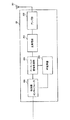
図12を参照して、ピコセルをカバーする基地局装置における下り送信フレームの生成工程について説明する。図12は、本実施の形態に係るピコセルをカバーする基地局装置における下りの送信フレームの生成工程の概念図である。なお、ここでは、キャリアインディケータに対して第2の解釈方法を適用した場合の送信フレームの生成工程について説明する。図12には、最大M個(CC#1〜CC#M)のコンポーネントキャリア数に対応可能な基地局構成が例示されている。
With reference to FIG. 12, the production | generation process of the downlink transmission frame in the base station apparatus which covers a pico cell is demonstrated. FIG. 12 is a conceptual diagram of a downlink transmission frame generation process in the base station apparatus covering the pico cell according to the present embodiment. Here, a transmission frame generation process when the second interpretation method is applied to the carrier indicator will be described. FIG. 12 illustrates a base station configuration that can support a maximum of M (
図12に示すように、送信フレームの生成工程は、スケジューラ211と、下り制御情報生成部212と、送信フレーム生成部213とを有している。スケジューラ211は、クロスキャリアスケジューリングを行う場合、下り制御情報生成部212にキャリアインデックスとサブバンドインデックス(ユーザデータの割当て周波数)とを指示する。スケジューラ211は、図6に示す例では、コンポーネントキャリアCC#2が強い干渉を受けているため、コンポーネントキャリアCC#1の下り制御情報生成部212にコンポーネントキャリアCC#1、CC#2を示す2種類のキャリアインデックスを指示する。
As illustrated in FIG. 12, the transmission frame generation process includes a
下り制御情報生成部212は、スケジューラ211に指示された各コンポーネントキャリアに対応したキャリアインディケータを決定する。この場合、キャリアインディケータの第1ビットは、コンポーネントキャリアの指示用であることを示す「0」に設定され、第2、第3ビットは、スケジューラ211に指示されたキャリアインデックスに設定される。
The downlink control
また、下り制御情報生成部212は、スケジューラ211に指示されたサブバンドインデックスにより、所定の割り当て周波数に各移動端末装置10に対するユーザデータ(PDSCH)を割り当てる。このように、下り制御情報生成部212は、スケジューラ211の指示により移動端末装置10にユーザデータが割当てられるコンポーネントキャリア、及びそのコンポーネントキャリアにおけるユーザデータの割り当て周波数を決定して、下り制御情報を生成する。
Further, the downlink control
図6に示す例では、コンポーネントキャリア#1の下り制御情報生成部212において、コンポーネントキャリア#1のユーザデータに対する下り制御情報と、コンポーネントキャリア#2のユーザデータに対する下り制御情報とがそれぞれ生成される。下り制御情報生成部212において生成された下り制御情報は、送信フレーム生成部213に入力される。
In the example illustrated in FIG. 6, the downlink control
また、スケジューラ211は、下り制御チャネルで同一サブフレーム以外の他のサブフレームに対するユーザデータをスケジューリングする場合、下り制御情報生成部212にサブフレームインデックスとサブバンドインデックスとを指示する。この場合、スケジューラ211は、サブフレーム毎にマクロセルC2からの干渉を受ける制御チャネルと干渉を受けない制御チャネルとを判別する。この制御チャネルの判別は、ピコセルC1及びマクロセルC2の無線フレームの時間軸方向のシフト量とマクロセルC2の無線フレームのブランク位置とに基づいて行われる。スケジューラ211は、マクロセルC2からの無線フレームのブランク期間に対応する制御チャネルをマクロセルC2からの干渉を受けると判別し、それ以外の制御チャネルを、干渉を受けないと判別する。
Also, when scheduling user data for other subframes other than the same subframe on the downlink control channel, the
そして、スケジューラ211は、マクロセルC2からの干渉を受けない下り制御チャネルの下り制御情報の生成時に、対応するサブフレーム及び干渉を受ける下り制御チャネルの後続サブフレームのサブフレームインデックスを指示する。例えば、図5では、スケジューラ211は、サブフレーム#1の下り制御情報の生成時に、サブフレーム#1及びサブフレーム#2のサブフレームインデックスを指示する。
Then, the
下り制御情報生成部212は、スケジューラ211に指示された各サブフレームに対応したキャリアインディケータを決定する。この場合、キャリアインディケータの第1ビットは、サブフレームの指示用であることを示す「1」に設定され、第2、第3ビットは、スケジューラ211に指示されたサブフレームインデックスに設定される。
The downlink control
また、下り制御情報生成部212は、スケジューラ211に指示されたサブバンドインデックスにより、所定の割り当て周波数に各移動端末装置10に対するユーザデータ(PDSCH)を割り当てる。このように、下り制御情報生成部212は、スケジューラ211の指示により移動端末装置10にユーザデータが割当てられるサブフレーム、及びそのサブフレームにおける割り当て周波数を決定して、下り制御情報を生成する。
Further, the downlink control
図5に示す例では、下り制御情報生成部212のサブフレーム#1に対する下り制御情報の生成時に、サブフレーム#1のユーザデータに対する下り制御情報と、サブフレーム#2のユーザデータに対する下り制御情報とがそれぞれ生成される。下り制御情報生成部212において生成された下り制御情報は、送信フレーム生成部213に入力される。
In the example illustrated in FIG. 5, when the downlink control
送信フレーム生成部213は、下り制御情報とユーザデータ(PDSCH)とを多重し、その他送信処理を施して下りの送信フレームを生成する。
The transmission
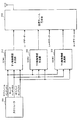
図13を参照して、ピコセルを介して通信する移動端末装置における下り送信フレームの受信工程について説明する。図13は、本実施の形態に係る移動端末装置における下り送信フレームの受信工程の概念図である。なお、ここでは、キャリアインディケータに対して第2の解釈方法を適用した場合の送信フレームの生成工程について説明する。 With reference to FIG. 13, the reception process of the downlink transmission frame in the mobile terminal apparatus which communicates via a pico cell is demonstrated. FIG. 13 is a conceptual diagram of a downlink transmission frame reception process in the mobile terminal apparatus according to the present embodiment. Here, a transmission frame generation process when the second interpretation method is applied to the carrier indicator will be described.
図13に示すように、送信フレームの受信工程は、下り制御チャネル復調部111と、下りデータチャネル復調部112とを有している。下り制御チャネル復調部111は、基地局装置20からの送信フレームから下り制御情報を復調し、下り制御情報からサブフレームインデックス、キャリアインデックス、サブバンドインデックスを取得する。この場合、下り制御チャネル復調部111は、復調した下り制御情報のキャリアインディケータからサブフレームインデックス、又はキャリアインデックスを取得する。また、下り制御チャネル復調部111は、復調した下り制御情報のスケジューリング情報からサブバンドインデックス(割り当て周波数)を取得する。サブフレームインデックス、キャリアインデックス、サブバンドインデックスは、下りデータチャネル復調部112に出力される。
As illustrated in FIG. 13, the transmission frame reception process includes a downlink control
下りデータチャネル復調部112は、サブフレームインデックス、キャリアインデックス、サブバンドインデックスに基づいて送信フレームからユーザデータを復調する。例えば、クロスキャリアスケジューリング時には、キャリアインデックス及びサブバンドインデックスによりユーザデータが復調される。また、下り制御チャネルで同一サブフレーム以外の他のサブフレームに対するユーザデータのスケジューリング時には、サブフレームインデックス及びサブバンドインデックスによりユーザデータが復調される。
The downlink data
なお、上記した送信フレームの生成工程及び送信フレームの受信工程では、キャリアインディケータが第2の解釈方法が適用される構成について説明したが、この構成に限定されるものではなく、例えば、第1の解釈方法が適用される構成でもよい。 In the transmission frame generation step and the transmission frame reception step described above, the configuration in which the second interpretation method is applied to the carrier indicator has been described. However, the present invention is not limited to this configuration. A configuration to which an interpretation method is applied may be used.
図16を参照して、マクロセルをカバーする基地局装置における下り送信フレームの生成工程について説明する。図16は、本実施の形態に係るピコセルをカバーする基地局装置における下りの送信フレームの生成工程の概念図である。図16には、最大M個(CC#1〜CC#M)のコンポーネントキャリア数に対応可能な基地局構成が例示されている。
With reference to FIG. 16, the generation process of the downlink transmission frame in the base station apparatus which covers a macro cell is demonstrated. FIG. 16 is a conceptual diagram of a downlink transmission frame generation process in the base station apparatus covering the pico cell according to the present embodiment. FIG. 16 illustrates a base station configuration that can support a maximum of M (
図16に示すように、送信フレームの生成工程は、スケジューラ411と、下り制御情報生成部412と、送信フレーム生成部413とを有している。スケジューラ411は、下り制御情報生成部412にサブフレームインデックス、キャリアインデックス、サブバンドインデックス(ユーザデータの割当て周波数)を指示する。スケジューラ411は、例えば、コンポーネントキャリアCC#2が強い干渉を受ける場合、コンポーネントキャリアCC#1の下り制御情報生成部412にコンポーネントキャリアCC#1、CC#2を示す2種類のキャリアインデックスを指示する。
As illustrated in FIG. 16, the transmission frame generation process includes a
また、スケジューラ411は、オフに設定されていない下り制御チャネルの下り制御情報の生成時に、対応するサブフレーム及び下り制御チャネルがオフに設定される後続サブフレームのサブフレームインデックスを指示する。例えば、図14では、スケジューラ211は、サブフレーム#1の下り制御情報の生成時に、サブフレーム#1及びサブフレーム#2のサブフレームを示す2種類のサブフレームインデックスを指示する。
Also, the
下り制御情報生成部412は、スケジューラ411に指示されたキャリアインデックスとサブフレームインデックスとによりキャリアインディケータを決定する。この場合、キャリアインディケータは、図15に示すような、キャリアインデックス及びサブフレームインデックスとの対応関係から決定される。
The downlink control
また、下り制御情報生成部412は、スケジューラ411に指示されたサブバンドインデックスにより、所定の割り当て周波数に各移動端末装置30に対するユーザデータ(PDSCH)を割り当てる。このように、下り制御情報生成部412は、スケジューラ411の指示により移動端末装置30にユーザデータが割当てられるコンポーネントキャリア、サブフレーム、割り当て周波数を決定して、下り制御情報を生成する。下り制御情報生成部412において生成された下り制御情報は、送信フレーム生成部413に入力される。
Also, the downlink control
送信フレーム生成部413は、下り制御情報とユーザデータ(PDSCH)とを多重し、その他送信処理を施して下りの送信フレームを生成する。
The transmission
図17を参照して、マクロセルを介して通信する移動端末装置における下り送信フレームの受信工程について説明する。図17は、本実施の形態に係る移動端末装置における下り送信フレームの受信工程の概念図である。 With reference to FIG. 17, the reception process of the downlink transmission frame in the mobile terminal apparatus which communicates via a macro cell is demonstrated. FIG. 17 is a conceptual diagram of a downlink transmission frame reception process in the mobile terminal apparatus according to the present embodiment.
図17に示すように、送信フレームの受信工程は、下り制御チャネル復調部311と、下りデータチャネル復調部312とを有している。下り制御チャネル復調部311は、基地局装置40からの送信フレームから下り制御情報を復調し、下り制御情報からサブフレームインデックス、キャリアインデックス、サブバンドインデックスを取得する。この場合、下り制御チャネル復調部311は、復調した下り制御情報のキャリアインディケータからサブフレームインデックス、又はキャリアインデックスを取得する。また、下り制御チャネル復調部311は、復調した下り制御情報のスケジューリング情報からサブバンドインデックス(割り当て周波数)を取得する。サブフレームインデックス、キャリアインデックス、サブバンドインデックスは、下りデータチャネル復調部312に出力される。
As shown in FIG. 17, the transmission frame reception process includes a downlink control
下りデータチャネル復調部312は、サブフレームインデックス、キャリアインデックス、サブバンドインデックスに基づいて送信フレームからユーザデータを復調する。
The downlink data
以上のように、本実施の形態に係る基地局装置20によれば、下り制御チャネルで同一サブフレーム以外に、キャリアインディケータに指示された他のサブフレームに対してユーザデータを割り当てることができる。よって、キャリアインディケータにより第1のシステムにより干渉を受ける制御チャネルのサブフレームを指示することで、干渉を受けないサブフレームの下り制御チャネルで、干渉を受けるサブフレームのユーザデータを割り当てることができる。また、キャリアインディケータを用いて、同一のサブフレーム以外にユーザデータが割り当てられる他のサブフレームを指示するため、簡易な制御構成とすることができる。
As described above, according to
なお、上記した実施の形態においては、小規模セルとしてピコセルをカバーする基地局装置について説明したが、この構成に限定されるものではない。基地局装置は、マクロセルからの干渉を受けるセルをカバーするものであればよく、フェムトセルやマイクロセル等をカバーする小型基地局装置であればよい。 In the above-described embodiment, a base station apparatus that covers a pico cell as a small cell has been described. However, the present invention is not limited to this configuration. The base station apparatus only needs to cover a cell that receives interference from a macro cell, and may be a small base station apparatus that covers a femto cell, a micro cell, or the like.
また、上記した実施の形態においては、ブランク期間は、ピコセルの無線フレームがマクロセルの無線フレームに干渉の影響を受けない期間を示すものである。このブランク期間は、マクロセルの無線フレームにおいて、全くデータを送信しない期間としてもよいし、干渉に影響を与えない程度にデータを送信する期間として規定されてもよい。また、ブランク期間は、マクロセルの無線フレームにおいて、ピコセルの無線フレームに対して干渉の影響を与えない程度の送信電力で送信される期間として規定されてもよい。また、ブランク期間は、マクロセルの無線フレームにおいて、ピコセルの無線フレームに対して影響を与えない程度の干渉量で送信される期間として規定されてもよい。 In the above-described embodiment, the blank period indicates a period in which the radio frame of the pico cell is not affected by the interference with the radio frame of the macro cell. This blank period may be a period during which no data is transmitted in the macro cell radio frame, or may be defined as a period during which data is transmitted to the extent that interference is not affected. Also, the blank period may be defined as a period in which the macro cell radio frame is transmitted with a transmission power that does not affect the pico cell radio frame. Further, the blank period may be defined as a period in which the macro cell radio frame is transmitted with an interference amount that does not affect the pico cell radio frame.
また、上記した実施の形態においては、ピコセルの基地局装置がマクロセルの基地局装置のシグナリングを受信する構成としてもよいし、その逆でもよい。また、マクロセルの基地局装置は、MBSFNサブフレームを用いる場合には、ピコセルの基地局装置にブランク位置を通知するようにする。 In the above-described embodiment, the pico cell base station apparatus may receive the signaling of the macro cell base station apparatus, or vice versa. Further, when using the MBSFN subframe, the macro cell base station apparatus notifies the pico cell base station apparatus of the blank position.
本発明は上記実施の形態に限定されず、様々変更して実施することが可能である。例えば、本発明の範囲を逸脱しない限りにおいて、上記説明におけるコンポーネントキャリアの割り当て、処理部の数、処理手順、コンポーネントキャリアの数、コンポーネントキャリアの集合数については適宜変更して実施することが可能である。その他、本発明の範囲を逸脱しないで適宜変更して実施することが可能である。 The present invention is not limited to the embodiment described above, and can be implemented with various modifications. For example, without departing from the scope of the present invention, the allocation of component carriers, the number of processing units, the processing procedure, the number of component carriers, and the number of sets of component carriers in the above description can be changed as appropriate. is there. Other modifications can be made without departing from the scope of the present invention.
1 無線通信システム
10 移動端末装置
20 基地局装置
101 送受信アンテナ
102 アンプ部
103 送受信部
104 ベースバンド信号処理部
105 アプリケーション部
111、311 制御チャネル復調部(指示情報取得部)
112、312 データチャネル復調部(データ復調部)
201 送受信アンテナ
202 アンプ部
203 送受信部
204 ベースバンド信号処理部
205 呼処理部
206 伝送路インターフェース
211、411 スケジューラ
212、412 下り制御情報生成部(指示情報生成部)
213、413 送信フレーム生成部
C1 ピコセル(小規模セル)
C2 マクロセル(大規模セル)
DESCRIPTION OF
112, 312 Data channel demodulator (data demodulator)
201 Transmission /
213, 413 Transmission frame generation unit C1 pico cell (small cell)
C2 Macro cell (large scale cell)
Claims (17)
前記第2のシステムのシステム帯域を構成する基本周波数ブロックに個別に割り当てられる指示情報であり、下り制御チャネルで同一のサブフレーム以外にユーザデータが割り当てられる他のサブフレームを指示する指示情報を生成する指示情報生成部と、
前記指示情報を含む送信フレームを生成する送信フレーム生成部とを備えたことを特徴とする基地局装置。 A base station apparatus in a second system that shares at least a part of a frequency band with a first system having a large-scale cell, covers a small-sized cell, and has a system band composed of a single or a plurality of basic frequency blocks. Yes,
Instruction information that is individually assigned to basic frequency blocks constituting the system band of the second system, and that generates instruction information that indicates other subframes to which user data is assigned in addition to the same subframe in the downlink control channel An instruction information generation unit for
A base station apparatus comprising: a transmission frame generation unit that generates a transmission frame including the instruction information.
基地局装置から、前記第2のシステムのシステム帯域を構成する基本周波数ブロックに個別に割り当てられる指示情報であり、下り制御チャネルで同一のサブフレーム以外にユーザデータが割り当てられる他のサブフレームを指示する指示情報を取得する指示情報取得部と、
前記指示情報に基づいてユーザデータを復調するデータ復調部とを備えたことを特徴とする移動端末装置。 A first system having a large-scale cell shares at least part of the frequency band, covers a small-sized cell, and communicates via a second system having a system band composed of a single or a plurality of basic frequency blocks. A mobile terminal device that
This is instruction information individually assigned to the basic frequency block constituting the system band of the second system from the base station apparatus, and indicates other subframes to which user data is assigned in addition to the same subframe in the downlink control channel An instruction information acquisition unit for acquiring instruction information to be
A mobile terminal apparatus comprising: a data demodulator that demodulates user data based on the instruction information.
前記第2のシステムのシステム帯域を構成する基本周波数ブロックに個別に割り当てられる指示情報であり、下り制御チャネルで同一のサブフレーム以外にユーザデータが割り当てられる他のサブフレームを指示する指示情報を生成するステップと、
前記指示情報を含む送信フレームを生成するステップとを有することを特徴とする通信制御方法。 Of the base station apparatus in the second system in which at least a part of the frequency band is shared with the first system having the large-scale cell, covers the small-sized cell, and has a system band composed of a single or a plurality of basic frequency blocks Communication control method,
Instruction information that is individually assigned to basic frequency blocks constituting the system band of the second system, and that generates instruction information that indicates other subframes to which user data is assigned in addition to the same subframe in the downlink control channel And steps to
Generating a transmission frame including the instruction information.
前記第2のシステムのシステム帯域を構成する基本周波数ブロックに個別に割り当てられる指示情報であり、下り制御チャネルで同一のサブフレーム以外に、下り制御チャネルが使用されない他のサブフレームに対しユーザデータの割り当てを指示する指示情報を生成する指示情報生成部と、
前記指示情報を含む送信フレームを生成する送信フレーム生成部とを備えたことを特徴とする基地局装置。 A base station apparatus in a second system which shares at least a part of a frequency band with a first system having a small cell, covers a large cell, and has a system band composed of a single or a plurality of basic frequency blocks. Yes,
Instruction information individually assigned to the basic frequency blocks constituting the system band of the second system, and in addition to the same subframe in the downlink control channel, the user data is transmitted to other subframes in which the downlink control channel is not used. An instruction information generating unit for generating instruction information for instructing allocation;
A base station apparatus comprising: a transmission frame generation unit that generates a transmission frame including the instruction information.
基地局装置から、前記第2のシステムのシステム帯域を構成する基本周波数ブロックに個別に割り当てられる指示情報であり、下り制御チャネルで同一のサブフレーム以外に、下り制御チャネルが使用されない他のサブフレームに対しユーザデータの割り当てを指示する指示情報を取得する指示情報取得部と、
前記指示情報に基づいてユーザデータを復調するデータ復調部とを備えたことを特徴とする移動端末装置。 A first system having a small cell shares at least a part of a frequency band, covers a large cell, and communicates via a second system having a system band composed of a single or a plurality of basic frequency blocks. A mobile terminal device that
Other subframes in which the downlink control channel is not used in addition to the same subframe in the downlink control channel, which is instruction information individually assigned from the base station apparatus to the basic frequency blocks constituting the system band of the second system An instruction information acquisition unit for acquiring instruction information for instructing the allocation of user data,
A mobile terminal apparatus comprising: a data demodulator that demodulates user data based on the instruction information.
前記第2のシステムのシステム帯域を構成する基本周波数ブロックに個別に割り当てられる指示情報であり、下り制御チャネルで同一のサブフレーム以外に、下り制御チャネルが使用されない他のサブフレームに対しユーザデータの割り当てを指示する指示情報を生成するステップと、
前記指示情報を含む送信フレームを生成するステップとを有することを特徴とする基地局装置。 The base station apparatus in the second system, which shares at least part of the frequency band with the first system having a small cell, covers a large cell, and has a system band composed of a single or a plurality of basic frequency blocks. Communication control method,
Instruction information individually assigned to the basic frequency blocks constituting the system band of the second system, and in addition to the same subframe in the downlink control channel, the user data is transmitted to other subframes in which the downlink control channel is not used. Generating instruction information for instructing allocation;
And a step of generating a transmission frame including the instruction information.
Priority Applications (5)
| Application Number | Priority Date | Filing Date | Title |
|---|---|---|---|
| JP2010087390A JP5114523B2 (en) | 2010-04-05 | 2010-04-05 | Base station apparatus, mobile terminal apparatus and communication control method |
| PCT/JP2011/058611 WO2011126008A1 (en) | 2010-04-05 | 2011-04-05 | Base station device, mobile terminal device and communication control method |
| CN201180027738.1A CN102934472B (en) | 2010-04-05 | 2011-04-05 | Base station apparatus, mobile terminal apparatus and communication control method |
| EP11765908.6A EP2557832A4 (en) | 2010-04-05 | 2011-04-05 | Base station device, mobile terminal device and communication control method |
| US13/261,462 US8705473B2 (en) | 2010-04-05 | 2011-04-05 | Base station apparatus, mobile terminal apparatus and communication control method |
Applications Claiming Priority (1)
| Application Number | Priority Date | Filing Date | Title |
|---|---|---|---|
| JP2010087390A JP5114523B2 (en) | 2010-04-05 | 2010-04-05 | Base station apparatus, mobile terminal apparatus and communication control method |
Publications (2)
| Publication Number | Publication Date |
|---|---|
| JP2011223114A JP2011223114A (en) | 2011-11-04 |
| JP5114523B2 true JP5114523B2 (en) | 2013-01-09 |
Family
ID=44762944
Family Applications (1)
| Application Number | Title | Priority Date | Filing Date |
|---|---|---|---|
| JP2010087390A Expired - Fee Related JP5114523B2 (en) | 2010-04-05 | 2010-04-05 | Base station apparatus, mobile terminal apparatus and communication control method |
Country Status (5)
| Country | Link |
|---|---|
| US (1) | US8705473B2 (en) |
| EP (1) | EP2557832A4 (en) |
| JP (1) | JP5114523B2 (en) |
| CN (1) | CN102934472B (en) |
| WO (1) | WO2011126008A1 (en) |
Families Citing this family (21)
| Publication number | Priority date | Publication date | Assignee | Title |
|---|---|---|---|---|
| US9106378B2 (en) | 2009-06-10 | 2015-08-11 | Qualcomm Incorporated | Systems, apparatus and methods for communicating downlink information |
| US9144037B2 (en) | 2009-08-11 | 2015-09-22 | Qualcomm Incorporated | Interference mitigation by puncturing transmission of interfering cells |
| US9277566B2 (en) * | 2009-09-14 | 2016-03-01 | Qualcomm Incorporated | Cross-subframe control channel design |
| US8942192B2 (en) | 2009-09-15 | 2015-01-27 | Qualcomm Incorporated | Methods and apparatus for subframe interlacing in heterogeneous networks |
| US9271167B2 (en) | 2010-04-13 | 2016-02-23 | Qualcomm Incorporated | Determination of radio link failure with enhanced interference coordination and cancellation |
| US9125072B2 (en) | 2010-04-13 | 2015-09-01 | Qualcomm Incorporated | Heterogeneous network (HetNet) user equipment (UE) radio resource management (RRM) measurements |
| US9392608B2 (en) | 2010-04-13 | 2016-07-12 | Qualcomm Incorporated | Resource partitioning information for enhanced interference coordination |
| US9226288B2 (en) | 2010-04-13 | 2015-12-29 | Qualcomm Incorporated | Method and apparatus for supporting communications in a heterogeneous network |
| US8792924B2 (en) * | 2011-05-06 | 2014-07-29 | Futurewei Technologies, Inc. | System and method for multi-cell access |
| JP5735127B2 (en) * | 2011-11-03 | 2015-06-17 | 京セラ株式会社 | Communication control method, base station, and user terminal |
| JP5893897B2 (en) * | 2011-11-11 | 2016-03-23 | 株式会社Nttドコモ | User apparatus, base station apparatus, and wireless communication method |
| JP5842608B2 (en) * | 2011-12-28 | 2016-01-13 | ソニー株式会社 | Base station, communication method and program |
| JP5890743B2 (en) | 2012-03-09 | 2016-03-22 | Kddi株式会社 | Wireless communication system, terminal, transmission station, and wireless communication program |
| US9049731B2 (en) * | 2012-12-03 | 2015-06-02 | At&T Mobility Ii Llc | Facilitation of bandwidth-based femto cell management |
| WO2014203620A1 (en) * | 2013-06-19 | 2014-12-24 | ソニー株式会社 | Communication control device, communication control method, and terminal device |
| CN104796920B (en) * | 2014-01-16 | 2019-02-12 | 电信科学技术研究院 | Data transmission method, base station and terminal device |
| KR101838840B1 (en) * | 2014-05-09 | 2018-03-14 | 후지쯔 가부시끼가이샤 | Wireless communications system, base station, and terminal |
| CN105578479A (en) * | 2014-10-15 | 2016-05-11 | 普天信息技术有限公司 | Shutting down method, base station and terminal of LTE cell |
| JP6755298B2 (en) * | 2015-07-06 | 2020-09-16 | テレフオンアクチーボラゲット エルエム エリクソン(パブル) | Resource allocation for data transmission in wireless systems |
| RU2018118565A (en) * | 2015-11-05 | 2019-12-05 | Нтт Докомо, Инк. | USER TERMINAL, BASIC RADIO STATION AND RADIO COMMUNICATION METHOD |
| KR102730802B1 (en) * | 2017-01-25 | 2024-11-18 | 삼성전자주식회사 | Method and apparatus for detecting the synchronization signal in wireless communication system |
Family Cites Families (12)
| Publication number | Priority date | Publication date | Assignee | Title |
|---|---|---|---|---|
| US6389010B1 (en) * | 1995-10-05 | 2002-05-14 | Intermec Ip Corp. | Hierarchical data collection network supporting packetized voice communications among wireless terminals and telephones |
| FI20055032A0 (en) * | 2005-01-25 | 2005-01-25 | Nokia Corp | Method for reducing interference of an indoor cell in a cellular wireless telecommunication system |
| CN101151818B (en) * | 2005-03-30 | 2011-08-10 | 摩托罗拉移动公司 | Method and apparatus for reducing round-trip latency and overhead within a communication system |
| US7574224B2 (en) * | 2005-06-13 | 2009-08-11 | Qualcomm Incorporated | Methods and apparatus for performing timing synchronization with base stations |
| CN101060700A (en) * | 2006-04-17 | 2007-10-24 | 北京三星通信技术研究有限公司 | An equipment and method for indicating and distributing the channel resources in the wireless communication system |
| JP4932555B2 (en) * | 2007-03-20 | 2012-05-16 | 株式会社エヌ・ティ・ティ・ドコモ | Base station, user apparatus, transmission method and reception method |
| GB2455056A (en) * | 2007-10-04 | 2009-06-03 | Fujitsu Ltd | Signalling mechanism in an OFDMA wireless communication network |
| CN101431365B (en) * | 2007-11-09 | 2012-08-08 | 电信科学技术研究院 | Data transmission method of TDD system |
| WO2009152866A1 (en) * | 2008-06-20 | 2009-12-23 | Nokia Siemens Networks Oy | Configuration of nodes for local data transmission which are under an overlay wide area macro network operated on the same frequency layer |
| KR20100011879A (en) * | 2008-07-25 | 2010-02-03 | 엘지전자 주식회사 | Method of receiving data in wireless communication system |
| US8842604B2 (en) * | 2008-09-15 | 2014-09-23 | Qualcomm Incorporated | Wireless communication systems with femto nodes |
| JP5131922B2 (en) | 2008-10-02 | 2013-01-30 | 富士機械製造株式会社 | Parts supply tape splicing equipment |
-
2010
- 2010-04-05 JP JP2010087390A patent/JP5114523B2/en not_active Expired - Fee Related
-
2011
- 2011-04-05 US US13/261,462 patent/US8705473B2/en not_active Expired - Fee Related
- 2011-04-05 WO PCT/JP2011/058611 patent/WO2011126008A1/en not_active Ceased
- 2011-04-05 CN CN201180027738.1A patent/CN102934472B/en not_active Expired - Fee Related
- 2011-04-05 EP EP11765908.6A patent/EP2557832A4/en not_active Withdrawn
Also Published As
| Publication number | Publication date |
|---|---|
| JP2011223114A (en) | 2011-11-04 |
| EP2557832A1 (en) | 2013-02-13 |
| EP2557832A4 (en) | 2017-01-04 |
| US20130077576A1 (en) | 2013-03-28 |
| WO2011126008A1 (en) | 2011-10-13 |
| US8705473B2 (en) | 2014-04-22 |
| CN102934472B (en) | 2016-03-30 |
| CN102934472A (en) | 2013-02-13 |
Similar Documents
| Publication | Publication Date | Title |
|---|---|---|
| JP5114523B2 (en) | Base station apparatus, mobile terminal apparatus and communication control method | |
| JP5411782B2 (en) | Base station apparatus, mobile terminal apparatus and communication control method | |
| JP6224358B2 (en) | Wireless base station, user terminal, and wireless communication method | |
| EP3375119B1 (en) | Techniques for providing channels in low latency lte wireless communications | |
| JP5809103B2 (en) | Wireless base station, user terminal, wireless communication system, and wireless communication method | |
| JP5265616B2 (en) | Wireless communication system | |
| JP5203400B2 (en) | Base station apparatus and system information notification method | |
| JP5432210B2 (en) | User terminal, radio base station, downlink control channel receiving method, and mobile communication system | |
| JP5785459B2 (en) | COMMUNICATION SYSTEM, BASE STATION DEVICE, MOBILE TERMINAL DEVICE, AND COMMUNICATION METHOD | |
| WO2013168794A1 (en) | Blind decoding method, wireless base station, user terminal, and wireless communications system | |
| CA2834556A1 (en) | Method and system for transmission and reception of signals and related method of signaling | |
| JP5192503B2 (en) | Information transmission method, base station apparatus and mobile station apparatus | |
| CN105191378A (en) | Wireless base station, user terminal, wireless communication system, and wireless communication method | |
| JP6106725B2 (en) | Wireless base station, user terminal, wireless communication system, and wireless communication method | |
| JP5366890B2 (en) | Base station apparatus, mobile terminal apparatus and communication control method | |
| WO2015115957A1 (en) | Transmitting and receiving nodes and methods therein for control channel transmissions in a radio communications network | |
| EP3809623B1 (en) | Techniques for allocating resources in low latency wireless communications | |
| JP5345254B2 (en) | Information transmission method, base station apparatus and mobile station apparatus |
Legal Events
| Date | Code | Title | Description |
|---|---|---|---|
| A621 | Written request for application examination |
Free format text: JAPANESE INTERMEDIATE CODE: A621 Effective date: 20110830 |
|
| A131 | Notification of reasons for refusal |
Free format text: JAPANESE INTERMEDIATE CODE: A131 Effective date: 20120710 |
|
| A521 | Request for written amendment filed |
Free format text: JAPANESE INTERMEDIATE CODE: A523 Effective date: 20120829 |
|
| TRDD | Decision of grant or rejection written | ||
| A01 | Written decision to grant a patent or to grant a registration (utility model) |
Free format text: JAPANESE INTERMEDIATE CODE: A01 Effective date: 20120918 |
|
| A01 | Written decision to grant a patent or to grant a registration (utility model) |
Free format text: JAPANESE INTERMEDIATE CODE: A01 |
|
| A61 | First payment of annual fees (during grant procedure) |
Free format text: JAPANESE INTERMEDIATE CODE: A61 Effective date: 20121015 |
|
| FPAY | Renewal fee payment (event date is renewal date of database) |
Free format text: PAYMENT UNTIL: 20151019 Year of fee payment: 3 |
|
| R150 | Certificate of patent or registration of utility model |
Free format text: JAPANESE INTERMEDIATE CODE: R150 |
|
| R250 | Receipt of annual fees |
Free format text: JAPANESE INTERMEDIATE CODE: R250 |
|
| R250 | Receipt of annual fees |
Free format text: JAPANESE INTERMEDIATE CODE: R250 |
|
| R250 | Receipt of annual fees |
Free format text: JAPANESE INTERMEDIATE CODE: R250 |
|
| LAPS | Cancellation because of no payment of annual fees |