JP6153574B2 - User terminal, radio base station, and radio communication method - Google Patents
User terminal, radio base station, and radio communication method Download PDFInfo
- Publication number
- JP6153574B2 JP6153574B2 JP2015159945A JP2015159945A JP6153574B2 JP 6153574 B2 JP6153574 B2 JP 6153574B2 JP 2015159945 A JP2015159945 A JP 2015159945A JP 2015159945 A JP2015159945 A JP 2015159945A JP 6153574 B2 JP6153574 B2 JP 6153574B2
- Authority
- JP
- Japan
- Prior art keywords
- user terminal
- subframe
- band
- csi
- signal
- Prior art date
- Legal status (The legal status is an assumption and is not a legal conclusion. Google has not performed a legal analysis and makes no representation as to the accuracy of the status listed.)
- Expired - Fee Related
Links
Images


Classifications
-
- H—ELECTRICITY
- H04—ELECTRIC COMMUNICATION TECHNIQUE
- H04J—MULTIPLEX COMMUNICATION
- H04J1/00—Frequency-division multiplex systems
-
- H—ELECTRICITY
- H04—ELECTRIC COMMUNICATION TECHNIQUE
- H04J—MULTIPLEX COMMUNICATION
- H04J11/00—Orthogonal multiplex systems, e.g. using WALSH codes
-
- H—ELECTRICITY
- H04—ELECTRIC COMMUNICATION TECHNIQUE
- H04W—WIRELESS COMMUNICATION NETWORKS
- H04W24/00—Supervisory, monitoring or testing arrangements
- H04W24/10—Scheduling measurement reports ; Arrangements for measurement reports
-
- H—ELECTRICITY
- H04—ELECTRIC COMMUNICATION TECHNIQUE
- H04W—WIRELESS COMMUNICATION NETWORKS
- H04W72/00—Local resource management
- H04W72/04—Wireless resource allocation
Landscapes
- Engineering & Computer Science (AREA)
- Computer Networks & Wireless Communication (AREA)
- Signal Processing (AREA)
- Mobile Radio Communication Systems (AREA)
Description
本発明は、次世代移動通信システムにおけるユーザ端末、無線基地局及び無線通信方法に関する。 The present invention relates to a user terminal, a radio base station, and a radio communication method in a next generation mobile communication system.
UMTS(Universal Mobile Telecommunications System)ネットワークにおいて、さらなる高速データレート、低遅延などを目的としてロングタームエボリューション(LTE:Long Term Evolution)が仕様化された(非特許文献1)。また、LTEからの更なる広帯域化及び高速化を目的として、LTEの後継システム(例えば、LTE−A(LTE-Advanced)、FRA(Future Radio Access)、4G、5Gなどともいう)も検討されている。 In the UMTS (Universal Mobile Telecommunications System) network, Long Term Evolution (LTE) has been specified for the purpose of higher data rate and low delay (Non-patent Document 1). In addition, LTE successor systems (for example, LTE-A (LTE-Advanced), FRA (Future Radio Access), 4G, 5G, etc.) have been studied for the purpose of further broadbandization and higher speed from LTE. Yes.
ところで、近年、通信装置の低コスト化に伴い、ネットワークに繋がれた装置が、人間の手を介さずに相互に通信して自動的に制御を行う機器間通信(M2M:Machine-to-Machine)の技術開発が盛んに行われている。特に、3GPP(Third Generation Partnership Project)は、M2Mの中でも機器間通信用のセルラシステムとして、MTC(Machine Type Communication)の最適化に関する標準化を進めている(非特許文献2)。MTC用ユーザ端末(MTC UE(User Equipment))は、例えば電気メータ、ガスメータ、自動販売機、車両、その他産業機器などの幅広い分野への利用が考えられている。 By the way, in recent years, with the cost reduction of communication devices, inter-device communication (M2M: Machine-to-Machine) in which devices connected to a network communicate with each other automatically without intervention of human hands. ) Is being actively developed. In particular, 3GPP (Third Generation Partnership Project) is proceeding with standardization regarding optimization of MTC (Machine Type Communication) as a cellular system for inter-device communication in M2M (Non-Patent Document 2). MTC user terminals (MTC UE (User Equipment)) are considered to be used in a wide range of fields such as electric meters, gas meters, vending machines, vehicles, and other industrial equipment.
MTCでは、コストの低減及びセルラシステムにおけるカバレッジエリアの改善の観点から、簡易なハードウェア構成で実現可能なMTC用ユーザ端末(LC(Low-Cost)−MTC UE、以下、単に、MTC端末という)の需要が高まっている。MTC端末は、上りリンク(UL)及び下りリンク(DL)の使用帯域を、システム帯域の一部の周波数ブロックに制限することで実現される。当該周波数ブロックは、例えば、1.4MHzで構成され、狭帯域(NB:Narrow Band)とも呼ばれる。 In MTC, from the viewpoint of cost reduction and improvement of coverage area in a cellular system, an MTC user terminal (LC (Low-Cost) -MTC UE, hereinafter simply referred to as MTC terminal) that can be realized with a simple hardware configuration. Demand is growing. The MTC terminal is realized by limiting the use band of the uplink (UL) and the downlink (DL) to some frequency blocks of the system band. The frequency block is composed of, for example, 1.4 MHz and is also called a narrow band (NB).
しかしながら、使用帯域がシステム帯域の一部の周波数ブロックに制限されるMTC端末に対して、従来のユーザ端末(例えば、LTE端末)と無線基地局との通信手法を適用する場合、MTC端末は、無線基地局との通信を適切に行うことができなくなる恐れがある。 However, when a conventional communication method between a user terminal (for example, an LTE terminal) and a radio base station is applied to an MTC terminal whose use band is limited to a part of the frequency blocks of the system band, the MTC terminal There is a risk that communication with the radio base station cannot be performed properly.
例えば、MTC端末に対する周波数スケジューリングを適用するためには、複数の周波数ブロックのチャネル状態情報(CSI:Channel State Information)の測定及び報告が必要となる。しかしながら、MTC端末は、単一のサブフレームにおいて、単一の周波数ブロックのCSIしか測定できないため、複数の周波数ブロックのCSIをどのように測定するかが問題となる。また、当該複数の周波数ブロックをどのようにMTC端末に設定するかも問題となる。 For example, in order to apply frequency scheduling to an MTC terminal, it is necessary to measure and report channel state information (CSI) of a plurality of frequency blocks. However, since the MTC terminal can measure only the CSI of a single frequency block in a single subframe, how to measure the CSI of a plurality of frequency blocks becomes a problem. Another problem is how to set the plurality of frequency blocks in the MTC terminal.
本発明はかかる点に鑑みてなされたものであり、システム帯域の一部の周波数ブロックに使用帯域が制限される場合に、適切に通信を行うことが可能なユーザ端末、無線基地局及び無線通信方法を提供することを目的の一つとする。 The present invention has been made in view of the above points, and a user terminal, a radio base station, and a radio communication capable of performing appropriate communication when a use band is limited to a part of the frequency blocks of the system band. One of the purposes is to provide a method.
本発明の一態様に係るユーザ端末は、システム帯域の一部の狭帯域に使用帯域が制限されるユーザ端末であって、周波数ホッピングされる狭帯域で下り制御チャネルを所定周期のサブフレームで監視して、下り制御情報を受信する受信部と、前記所定周期のサブフレームにおいて前記狭帯域でチャネル状態情報(CSI)を測定する測定部と、前記下り制御情報に含まれる報告要求に基づいて、前記CSIを送信する送信部と、を具備し、前記測定部は、前記所定周期のサブフレームで下りデータチャネルが割り当てられる場合、前記狭帯域での前記CSIの測定を中止することを特徴とする。
A user terminal according to one aspect of the present invention is a user terminal whose use band is limited to a narrow part of a system band, and monitors a downlink control channel in a subframe of a predetermined period in a narrow band that is frequency-hopped. A receiving unit that receives downlink control information, a measuring unit that measures channel state information (CSI) in the narrowband in the subframe of the predetermined period, and a report request included in the downlink control information, anda transmitter for transmitting the CSI, the measuring unit, when said predetermined cycle of the downlink data channel in a subframe are allocated, characterized by stops the measurement of the CSI in the narrowband .
本発明によれば、システム帯域の一部の周波数ブロックに使用帯域が制限されるユーザ端末が、適切に無線基地局との通信を行うことできる。 ADVANTAGE OF THE INVENTION According to this invention, the user terminal by which a use band is restrict | limited to a part of frequency block of a system band can communicate with a radio base station appropriately.
低コストMTC用のユーザ端末では、処理能力の低下を許容して、ハードウェア構成を簡略化することが検討されている。例えば、低コストMTC用のユーザ端末では、既存のユーザ端末に比べて、ピークレートの減少、トランスポートブロックサイズの制限、リソースブロック(RB(Resource Block)、PRB(Physical Resource Block)等とも呼ばれる。以下、PRBという)の制限、受信RF(Radio Frequency)の制限などを適用することが検討されている。 In a user terminal for low-cost MTC, it has been studied to simplify the hardware configuration while allowing a reduction in processing capability. For example, a user terminal for low-cost MTC is also referred to as a peak rate reduction, a transport block size limitation, a resource block (RB (Resource Block), PRB (Physical Resource Block)), or the like, compared to an existing user terminal. Hereinafter, application of restrictions such as PRB) and reception RF (Radio Frequency) restrictions is being studied.
ここで、既存のユーザ端末は、LTE端末、LTE−A端末、LTE UE(User Equipment)、ノーマルUE、非MTC端末、単に、ユーザ端末、UEなどと呼ばれる。また、MTC端末は、単に、ユーザ端末、UEなどとも呼ばれる。以下では、説明の便宜上、既存のユーザ端末をLTE端末と呼び、MTC(低コストMTC)用のユーザ端末をMTC端末と呼ぶ。 Here, the existing user terminals are referred to as LTE terminals, LTE-A terminals, LTE UE (User Equipment), normal UEs, non-MTC terminals, simply user terminals, UEs, and the like. An MTC terminal is also simply called a user terminal, UE, or the like. Hereinafter, for convenience of explanation, an existing user terminal is referred to as an LTE terminal, and a user terminal for MTC (low cost MTC) is referred to as an MTC terminal.
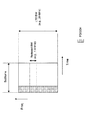
図1は、LTE端末とMTC端末との使用帯域の説明図である。図1に示すように、LTE端末の使用帯域の上限は、システム帯域(例えば、20MHz(=100PRB)、1コンポーネントキャリアなど)に設定される。一方、MTC端末の使用帯域の上限は、システム帯域の一部の周波数ブロック(例えば、1.4MHz(=6PRB))に制限される。以下、当該周波数ブロックを「狭帯域(NB)」とも呼ぶ。 FIG. 1 is an explanatory diagram of bands used by LTE terminals and MTC terminals. As shown in FIG. 1, the upper limit of the use band of the LTE terminal is set to a system band (for example, 20 MHz (= 100 PRB), one component carrier, etc.). On the other hand, the upper limit of the band used by the MTC terminal is limited to a part of the frequency band of the system band (for example, 1.4 MHz (= 6 PRB)). Hereinafter, the frequency block is also referred to as “narrow band (NB)”.
また、MTC端末は、LTE/LTE−Aのシステム帯域内で動作することが検討されている。この場合、MTC端末とLTE端末との周波数分割多重をサポート可能となる。このように、MTC端末は、サポートする最大の帯域がシステム帯域の一部の周波数ブロック(狭帯域)であるユーザ端末ともいえ、LTE/LTE−Aのシステム帯域よりも狭い帯域の送受信性能を有するユーザ端末ともいえる。 Further, it is considered that the MTC terminal operates within the LTE / LTE-A system band. In this case, frequency division multiplexing between the MTC terminal and the LTE terminal can be supported. As described above, the MTC terminal can be said to be a user terminal whose maximum band to be supported is a partial frequency block (narrow band) of the system band, and has a transmission / reception performance in a band narrower than the LTE / LTE-A system band. It can also be said to be a user terminal.
図2は、MTC端末の使用帯域となる狭帯域の配置の説明図である。図2Aに示すように、狭帯域(例えば、1.4MHz)をシステム帯域(例えば、20MHz)内の特定の周波数位置に固定することが想定される。この場合、トラヒックが当該特定の周波数(例えば、中心周波数)に集中する恐れがある。また、周波数ダイバーシチ効果が得られないため、周波数利用効率が低下する恐れがある。 FIG. 2 is an explanatory diagram of an arrangement of narrow bands that are used bands of the MTC terminal. As shown in FIG. 2A, it is assumed that a narrow band (for example, 1.4 MHz) is fixed at a specific frequency position in a system band (for example, 20 MHz). In this case, traffic may concentrate on the specific frequency (for example, the center frequency). Moreover, since the frequency diversity effect cannot be obtained, the frequency utilization efficiency may be reduced.
そこで、図2Bに示すように、狭帯域(例えば、1.4MHz)を所定の期間(例えば、サブフレーム)でシステム帯域(例えば、20MHz)内の異なる周波数位置(周波数リソース)に変化させることが想定される。この場合、MTC端末のトラヒックを分散させることができる。また、周波数ダイバーシチ効果が得られるので、周波数利用効率の低下を抑制できる。 Therefore, as shown in FIG. 2B, a narrow band (for example, 1.4 MHz) can be changed to a different frequency position (frequency resource) in the system band (for example, 20 MHz) in a predetermined period (for example, a subframe). is assumed. In this case, the traffic of the MTC terminals can be distributed. In addition, since a frequency diversity effect can be obtained, it is possible to suppress a decrease in frequency utilization efficiency.
図2Bに示すように、MTC端末の使用帯域となる狭帯域の周波数位置が可変である場合、MTC端末は、狭帯域に対する周波数ホッピング又は周波数スケジューリングの適用を考慮して、RFの再調整(retuning)機能を有することが好ましい。 As shown in FIG. 2B, when the frequency position of the narrow band that is the band used by the MTC terminal is variable, the MTC terminal considers the application of frequency hopping or frequency scheduling to the narrow band and performs RF retuning (retuning). ) It is preferable to have a function.
ところで、MTC端末は、システム帯域の一部の狭帯域(例えば、1.4MHz)のみをサポートするため、システム帯域全体に渡って配置される下り制御チャネル(PDCCH:Physical Downlink Control Channel)を検出できない。このため、狭帯域に配置されるMTC用下り制御チャネル(MPDCCH:Machine type communication PDCCH)を用いて、下り共有チャネル(PDSCH)や上り共有チャネル(PUSCH:Physical Uplink Shared Channel)のリソース割り当てを行うことが検討されている。 By the way, since the MTC terminal supports only a narrow band (for example, 1.4 MHz) of a part of the system band, it cannot detect a downlink control channel (PDCCH: Physical Downlink Control Channel) arranged over the entire system band. . For this reason, resource allocation of a downlink shared channel (PDSCH) or an uplink shared channel (PUSCH: Physical Uplink Shared Channel) is performed using an MTC downlink control channel (MPDCCH: Machine type communication PDCCH) arranged in a narrow band. Is being considered.
ここで、MTC用下り制御チャネル(MPDCCH)は、システム帯域の一部の狭帯域で送信される下り制御チャネルであり、LTE用又はMTC用の下り共有チャネル(PDSCH:Physical Downlink Shared Channel)と周波数分割多重されてもよい。MPDCCHは、M−PDCCH(Machine type communication−PDCCH)、拡張下り制御チャネル(EPDCCH:Enhanced Physical Downlink Control Channel)等と呼ばれてもよい。MPDCCHにより、PDSCHの割り当てに関する情報(例えば、DL(Downlink)グラント)、PUSCHの割り当てに関する情報(例えば、UL(Uplink)グラント)等を含む下り制御情報(DCI:Downlink Control Channel)が伝送される。 Here, the downlink control channel for MTC (MPDCCH) is a downlink control channel transmitted in a narrow band that is a part of the system band, and is a downlink shared channel (PDSCH: Physical Downlink Shared Channel) for LTE or MTC. It may be divided and multiplexed. The MPDCCH may be referred to as M-PDCCH (Machine type communication-PDCCH), an enhanced downlink control channel (EPDCCH), or the like. MPDCCH transmits downlink control information (DCI: Downlink Control Channel) including information related to PDSCH allocation (for example, DL (Downlink) grant), information related to PUSCH allocation (for example, UL (Uplink) grant), and the like.
なお、MPDCCH以外にも、MTC端末によって用いられるチャネルは、同じ用途で用いられる既存のチャネルにMTCを示す「M」を付して表されてもよい。例えば、MPDCCHにより割り当てられたPDSCHは、MPDSCH(Machine type communication PDSCH)、M−PDSCH(Machine type communication−PDSCH)などと呼ばれてもよい。同様に、MPDCCHにより割り当てられたPUSCHは、MPUSCH(Machine type communication PUSCH)、M−PUSCH(Machine type communication−PUSCH)などと呼ばれてもよい。 In addition to the MPDCCH, a channel used by an MTC terminal may be represented by adding “M” indicating MTC to an existing channel used in the same application. For example, PDSCH allocated by MPDCCH may be called MPDSCH (Machine type communication PDSCH), M-PDSCH (Machine type communication-PDSCH), etc. Similarly, PUSCH allocated by MPDCCH may be called MPUSCH (Machine type communication PUSCH), M-PUSCH (Machine type communication-PUSCH), or the like.
図3は、PDSCHの周波数スケジューリングの一例を示す図である。図3に示すように、MTC端末に対するPDSCHの周波数スケジューリングを適用する場合、MTC端末の使用帯域の候補として複数の狭帯域(周波数ブロック)が設定(configure)されてもよい。各狭帯域は、複数のPRB(例えば、6PRB)から構成され、PRBセットと呼ばれてもよい。複数のPRBセットは、上位レイヤシグナリング(例えば、RRC(Radio Resource Control)シグナリングや報知信号など)により無線基地局からMTC端末に通知されてもよいし、予めMTC端末に設定されていてもよい。 FIG. 3 is a diagram illustrating an example of PDSCH frequency scheduling. As shown in FIG. 3, when applying PDSCH frequency scheduling for an MTC terminal, a plurality of narrow bands (frequency blocks) may be configured as candidates for bands used by the MTC terminal. Each narrow band is composed of a plurality of PRBs (for example, 6 PRBs) and may be referred to as a PRB set. The plurality of PRB sets may be notified from the radio base station to the MTC terminal by higher layer signaling (for example, RRC (Radio Resource Control) signaling or a broadcast signal), or may be set in advance in the MTC terminal.
無線基地局は、上記複数の狭帯域の中から1つの狭帯域を選択する。例えば、無線基地局は、MTC端末で測定された複数の狭帯域それぞれのCSIに基づいて、1つの狭帯域を選択してもよい。また、無線基地局は、選択された狭帯域を構成する少なくとも一つのPRBに対して、MTC端末に対するPDSCHを割り当てる(スケジューリングする)。 The radio base station selects one narrow band from the plurality of narrow bands. For example, the radio base station may select one narrow band based on the CSI of each of a plurality of narrow bands measured by the MTC terminal. Also, the radio base station allocates (schedules) the PDSCH for the MTC terminal to at least one PRB constituting the selected narrow band.
MPDCCHにより伝送されるDCIには、上記複数の狭帯域から選択された狭帯域を示す情報が含まれる。また、当該DCIには、選択された狭帯域内でPDSCHに割り当てられた少なくとも1つのPRBを示す情報(例えば、リソース割り当て(RA:Resource Allocation)フィールド)が含まれる。例えば、図3では、MTC端末は、MPDCCHが送信された次のサブフレームで、DCIにより指定された狭帯域の少なくとも1つのPRBに割り当てられるPDSCHを受信する。なお、PDSCHは、MPDCCHと同じサブフレームで受信されてもよい。 DCI transmitted by MPDCCH includes information indicating a narrow band selected from the plurality of narrow bands. In addition, the DCI includes information (for example, a resource allocation (RA) field) indicating at least one PRB allocated to the PDSCH within the selected narrow band. For example, in FIG. 3, the MTC terminal receives a PDSCH assigned to at least one PRB in a narrow band specified by DCI in the next subframe in which the MPDCCH is transmitted. PDSCH may be received in the same subframe as MPDCCH.
このように、複数の狭帯域から1つの狭帯域を動的に選択し、選択された狭帯域の少なくとも1つのPRBにPDSCHが割り当てられる場合、周波数スケジューリングゲインを得ながら、当該PRBを示すRAフィールドに要するビット数を削減できる。 In this way, when one narrow band is dynamically selected from a plurality of narrow bands, and the PDSCH is allocated to at least one PRB of the selected narrow band, the RA field indicating the PRB is obtained while obtaining the frequency scheduling gain. Can reduce the number of bits required.
なお、図3では、MTC端末に設定される狭帯域(周波数ブロック、PRBセットなどともいう)の数は2であるが、2に限られない。また、MPDCCHは、任意の狭帯域に割り当てられればよい。MPDCCHの割り当てに関する情報は、上位レイヤシグナリング(例えば、RRCシグナリングや報知情報など)で通知されてもよいし、予めMTC端末に設定されていてもよい。 In FIG. 3, the number of narrow bands (also referred to as frequency blocks, PRB sets, etc.) set in the MTC terminal is two, but is not limited to two. Moreover, MPDCCH should just be allocated to arbitrary narrow bands. Information on MPDCCH allocation may be notified by higher layer signaling (for example, RRC signaling or broadcast information), or may be set in advance in the MTC terminal.
また、図3では、MPDCCH/PDSCHは、単一のサブフレームで送信されるが、同一のMPDCCH/PDSCHが、複数のサブフレームに渡って繰り返し(repetition)送信されてもよい。ユーザ端末は、複数のサブフレームに渡るMPDCCH/PDSCHを合成することで、所望の信号対干渉雑音比(SINR:Signal-to-Interference plus Noise Ratio)を満たすことができる。この結果、MTCのカバレッジを拡大できる。 In FIG. 3, MPDCCH / PDSCH is transmitted in a single subframe, but the same MPDCCH / PDSCH may be transmitted repeatedly over a plurality of subframes. The user terminal can satisfy a desired signal-to-interference plus noise ratio (SINR) by combining MPDCCH / PDSCH over a plurality of subframes. As a result, the coverage of MTC can be expanded.
しかしながら、使用帯域がシステム帯域の一部の狭帯域(周波数ブロック)に制限されるMTC端末に対してLTE端末と無線基地局との通信手法を適用する場合、MTC端末は、無線基地局との通信を適切に行うことができなくなる恐れがある。 However, when a communication method between an LTE terminal and a radio base station is applied to an MTC terminal whose use band is limited to a part of a narrow band (frequency block) of the system band, the MTC terminal There is a risk that communication cannot be performed properly.
具体的には、図3に示すように、MTC端末に対するPDSCHの周波数スケジューリングを適用するためには、使用帯域の候補となる複数の狭帯域(周波数ブロック)におけるCSIの測定及び/又は報告が必要となることが想定される。しかしながら、MTC端末は、単一のサブフレームにおいて、単一の狭帯域におけるCSIの測定しか実施できない。このため、1.4MHzを超える広帯域(特に、複数の狭帯域)に対するCSIの測定及び/又は報告の手法を確立することが望まれる。 Specifically, as shown in FIG. 3, in order to apply the PDSCH frequency scheduling to the MTC terminal, it is necessary to measure and / or report CSI in a plurality of narrow bands (frequency blocks) that are candidates for use bands. It is assumed that However, the MTC terminal can only perform CSI measurement in a single narrowband in a single subframe. For this reason, it is desired to establish a CSI measurement and / or reporting technique for a wide band (in particular, a plurality of narrow bands) exceeding 1.4 MHz.
例えば、LTE端末のように、上り制御チャネル(PUCCH:Physical Uplink Control Channel)を用いてCSIを周期的に測定及び報告させることも考えられる。しかしながら、LTE端末と比べてトラヒック頻度の少ないMTC端末に対して、LTE端末のCSIの測定及び報告手法を適用する場合、上り伝送効率の低下や、消費電力の増大を引き起こす恐れがある。 For example, it is also conceivable to periodically measure and report CSI using an uplink control channel (PUCCH) like an LTE terminal. However, when the CSI measurement and reporting method of the LTE terminal is applied to an MTC terminal that has less traffic frequency than the LTE terminal, there is a risk that the uplink transmission efficiency is decreased and the power consumption is increased.
また、図3に示すように、MTC端末に対するPDSCHの周波数スケジューリングを適用する場合、使用帯域の候補となる複数の狭帯域(周波数ブロック)をどのように設定するかも問題となる。例えば、当該複数の狭帯域が上位レイヤシグナリングにより設定される場合、当該複数の狭帯域を指定する上位レイヤメッセージをどのリソースで通知するかが問題となる。 In addition, as shown in FIG. 3, when PDSCH frequency scheduling is applied to an MTC terminal, how to set a plurality of narrow bands (frequency blocks) that are candidates for use bands is also a problem. For example, when the plurality of narrow bands are set by upper layer signaling, a problem arises as to which resource notifies the upper layer message designating the plurality of narrow bands.
このように、将来の無線通信システム(例えば、LTE Rel.13以降)では、使用帯域がシステム帯域の一部の狭帯域(周波数ブロック)に制限されるMTC端末に適するCSIの測定及び/又は報告手法や、使用帯域の設定手法が望まれる。 As described above, in future wireless communication systems (for example, LTE Rel. 13 or later), CSI measurement and / or reporting suitable for MTC terminals whose use band is limited to a narrow band (frequency block) of a part of the system band. A method and a setting method of a use band are desired.
そこで、本発明者らは、第1に、MPDCCHが複数のサブフレームに渡る繰り返しなしで送信される場合にも、所定周期でMPDCCHを受信(監視)して、CSIを測定することを着想し、本発明に至った。また、本発明者らは、第2に、初期設定される少なくとも一つの狭帯域を用いて、使用帯域の候補となる複数の狭帯域を指定する上位レイヤメッセージを伝送することを着想し、本発明に至った。 Therefore, the present inventors firstly conceived that even when MPDCCH is transmitted without repetition over a plurality of subframes, MPSICH is received (monitored) at a predetermined period and CSI is measured. The present invention has been reached. In addition, the present inventors secondly conceived that at least one narrow band that is initially set is used to transmit an upper layer message that designates a plurality of narrow bands that are candidates for the used band, Invented.
以下、本発明の一実施形態に係る無線通信方法について説明する。なお、以下において、システム帯域の一部の狭帯域(周波数ブロック)は、1.4MHzであり、6リソースブロック(PRB)で構成されるものとするが、これに限られない。 Hereinafter, a wireless communication method according to an embodiment of the present invention will be described. In the following, a narrow band (frequency block) of a part of the system band is 1.4 MHz and is configured by 6 resource blocks (PRB), but is not limited thereto.
また、以下では、システム帯域の一部の狭帯域で送信されるMPDCCH、PDSCH、その他の信号を、繰り返しなしで送信する場合を想定するが、これらの信号を複数のサブフレームに渡って繰り返し送信してもよい。 In the following, it is assumed that MPDCCH, PDSCH, and other signals transmitted in a narrow part of the system band are transmitted without repetition, but these signals are repeatedly transmitted over a plurality of subframes. May be.
(第1の態様)
第1の態様では、システム帯域の一部の狭帯域(周波数ブロック)に使用帯域が制限されるMTC端末(ユーザ端末)は、所定周期のサブフレームにおいて、複数のサブフレームに渡る繰り返しなしで送信されるMPDCCH(下り制御信号)を受信(監視)し、CSIを測定し、測定されたCSIを送信する。
(First aspect)
In the first mode, an MTC terminal (user terminal) whose use band is limited to a narrow band (frequency block) of a part of the system band transmits without repetition over a plurality of subframes in a subframe of a predetermined period. MPDCCH (downlink control signal) to be received (monitored), CSI is measured, and the measured CSI is transmitted.
具体的には、MTC端末は、所定周期のサブフレームにおいて、周波数ホッピングされる狭帯域(周波数ブロック)で送信されるMPDCCHを受信してもよい。MTC端末は、当該所定周期のサブフレームにおいて、当該周波数ホッピングされる狭帯域(周波数ブロック)のCSIを測定してもよい。ここで、周波数ホッピングされる狭帯域(周波数ブロック)とは、MPDCCHを受信するための周波数ブロックであり、繰り返しが適用されない場合でもMPDCCHを受信するための周波数ブロックには周波数ホッピングが適用されるが、DCIは1サブフレームで送信されるため、必ずしもDCIを送信するMPDCCHに対して周波数ホッピングが適用されるとは限らない。一方、繰り返しが適用される場合は、DCIが複数サブフレームで送信されるため、周波数ホッピングされる周波数ブロックに従い、DCIを送信するMPDCCHに対しても周波数ホッピングが適用される。 Specifically, the MTC terminal may receive MPDCCH transmitted in a narrow band (frequency block) that is frequency hopped in a subframe of a predetermined period. The MTC terminal may measure the narrowband (frequency block) CSI subjected to the frequency hopping in the subframe of the predetermined period. Here, a narrow band (frequency block) to be frequency hopped is a frequency block for receiving MPDCCH, and frequency hopping is applied to a frequency block for receiving MPDCCH even when repetition is not applied. Since DCI is transmitted in one subframe, frequency hopping is not always applied to MPDCCH that transmits DCI. On the other hand, when repetition is applied, since DCI is transmitted in a plurality of subframes, frequency hopping is also applied to MPDCCH that transmits DCI according to the frequency block to be frequency hopped.
また、MTC端末は、MPDCCH(で伝送されるDCI)に測定要求(例えば、測定を要求する値のAperiodic CSI trigger)が含まれる場合、当該所定周期のサブフレームにおいて、周波数ホッピングされる周波数ブロックのCSIを測定してもよい。 Further, when the MDC terminal includes a measurement request (for example, an Aperiodic CSI trigger having a value that requires measurement) in the MPDCCH (DCI transmitted in the MPDCCH), in the subframe of the predetermined period, the frequency block to be frequency hopped CSI may be measured.
図4は、第1の態様に係る狭帯域の周波数ホッピング例を示す図である。なお、図4に示す周波数ホッピングパターンは例示にすぎず、MPDCCHが受信(監視)される狭帯域は、所定の周波数ホッピングパターンで周波数ホップ(frequency-hopped)されればよい。例えば、図4に示す周波数ホッピングパターンでは、MPDCCHが周波数ホップされる狭帯域の数は、4であるが、4以外であってもよい。また、周波数ホッピングパターンの周期も図4に示すものに限られない。 FIG. 4 is a diagram illustrating an example of narrowband frequency hopping according to the first aspect. Note that the frequency hopping pattern shown in FIG. 4 is merely an example, and a narrow band in which MPDCCH is received (monitored) may be frequency-hopped with a predetermined frequency hopping pattern. For example, in the frequency hopping pattern shown in FIG. 4, the number of narrow bands in which MPDCCH is frequency-hopped is 4, but may be other than 4. Further, the period of the frequency hopping pattern is not limited to that shown in FIG.
図4Aでは、8サブフレームで4つの狭帯域にホッピングさせる周波数ホッピングパターンが例示される。また、図4Bでは、16サブフレームで4つの狭帯域にホッピングさせる周波数ホッピングパターンが例示される。 FIG. 4A illustrates a frequency hopping pattern in which hopping is performed in four narrow bands in 8 subframes. FIG. 4B illustrates a frequency hopping pattern in which hopping is performed in four narrow bands in 16 subframes.
図4A及び図4Bにおいて、MTC端末は、所定周期(図4Aでは2ms、図4Bでは4ms)のサブフレーム(MPDCCH monitoring subframeともいう)において、周波数ホッピングされる狭帯域で、繰り返しなしで送信されるMPDCCHを受信(監視)する。図4A及び図4Bにおいて、MTC端末は、所定周期(図4Aでは2ms、図4Bでは4ms)のサブフレームにおいて、周波数ホッピングされる狭帯域のCSIを測定する。 4A and 4B, the MTC terminal is transmitted without repetition in a narrow band subjected to frequency hopping in a subframe (also referred to as MPDCCH monitoring subframe) of a predetermined period (2 ms in FIG. 4A and 4 ms in FIG. 4B). MPDCCH is received (monitored). 4A and 4B, the MTC terminal measures the narrowband CSI subjected to frequency hopping in a subframe of a predetermined period (2 ms in FIG. 4A and 4 ms in FIG. 4B).
また、図4A及び図4Bにおいて、MTC端末は、受信したMPDCCHで伝送されるDCIに測定要求が含まれる場合に、CSIを測定してもよい。ここで、測定要求は、CSIの測定を要求するビット値(例えば、“1”など)であってもよい。測定要求は、CSIの測定を要求するだけでなく、CSIの測定が要求される狭帯域(周波数ブロック)を示してもよい。また、測定要求は、CSIの測定だけでなく報告を要求する測定及び報告要求であってもよい。以上のような測定及び/又は報告要求は、非周期CSIトリガフィールド(Aperiodic CSI trigger field)等であってもよい。 4A and 4B, the MTC terminal may measure the CSI when the measurement request is included in the DCI transmitted on the received MPDCCH. Here, the measurement request may be a bit value (for example, “1” or the like) for requesting CSI measurement. The measurement request may indicate not only a CSI measurement but also a narrow band (frequency block) in which the CSI measurement is required. The measurement request may be a measurement request and a report request for requesting a report as well as a CSI measurement. The measurement and / or report request as described above may be an aperiodic CSI trigger field.
例えば、MTC端末は、所定周期のサブフレーム(例えば、図4Aの左から1番目のサブフレーム)でMPDCCHを受信し、当該MTC端末に対するDCIを検出し、当該DCIに測定要求が含まれる場合、CSIを測定してもよい。この場合、MTC端末は、周波数ホッピングされる狭帯域のCSIを測定することが好適であるが、これに限られない。 For example, when the MTC terminal receives MPDCCH in a subframe of a predetermined period (for example, the first subframe from the left in FIG. 4A), detects the DCI for the MTC terminal, and the DCI includes a measurement request, CSI may be measured. In this case, the MTC terminal preferably measures the narrowband CSI subjected to frequency hopping, but is not limited thereto.
また、MTC端末は、所定周期のサブフレームにおいてPDSCH(下りデータ信号)が割り当てられる場合(例えば、図4Aの左から7番目及び11番目のサブフレーム)、PDSCHが割り当てられる狭帯域のCSIを測定してもよい。例えば、図4Aでは、左から5番目のサブフレームで受信されるMPDCCHに、左から7番目のサブフレームのPDSCHを割り当てる下りグラントが含まれる。このため、MTC端末は、左から7番目のサブフレームで、周波数ホッピングされる狭帯域の代わりに、下りグラントにより割り当てられる狭帯域のCSIを測定する。 Also, when a PDSCH (downlink data signal) is allocated in a subframe of a predetermined period (for example, the seventh and eleventh subframes from the left in FIG. 4A), the MTC terminal measures the narrowband CSI to which the PDSCH is allocated. May be. For example, in FIG. 4A, the downlink grant for allocating the PDSCH of the seventh subframe from the left is included in the MPDCCH received in the fifth subframe from the left. Therefore, the MTC terminal measures the narrowband CSI assigned by the downlink grant instead of the narrowband that is frequency-hopped in the seventh subframe from the left.
或いは、MTC端末は、所定周期のサブフレーム(例えば、図4Aの左から7番目及び11番目のサブフレーム)においてPDSCHが割り当てられる場合、当該所定周期のサブフレームにおけるCSIの測定を中止してもよい。 Alternatively, when the PDSCH is allocated in a subframe having a predetermined cycle (for example, the seventh and eleventh subframes from the left in FIG. 4A), the MTC terminal may stop measuring CSI in the subframe having the predetermined cycle. Good.
また、MTC端末は、所定周期のサブフレーム以外のサブフレーム(例えば、図4Bの左から7番目のサブフレーム)においてPDSCHが割り当てられる場合、当該サブフレームでPDSCHが割り当てられる狭帯域のCSIを測定してもよい。 In addition, when a PDSCH is allocated in a subframe other than a subframe of a predetermined period (for example, the seventh subframe from the left in FIG. 4B), the MTC terminal measures the narrowband CSI to which the PDSCH is allocated in the subframe. May be.
例えば、図4Bでは、左から5番目のサブフレームで受信されるMPDCCHに、左から7番目のサブフレームのPDSCHを割り当てる下りグラントが含まれる。このため、MTC端末は、所定周期のサブフレームではない左から7番目のサブフレームで、下りグラントにより割り当てられる狭帯域のCSIを測定する。このように、CSIを測定するサブフレームは、MPDCCHが受信(監視)される所定周期のサブフレームと同一であってもよいし、異なってもよい。 For example, in FIG. 4B, a downlink grant that assigns the PDSCH of the seventh subframe from the left to the MPDCCH received in the fifth subframe from the left is included. Therefore, the MTC terminal measures the narrowband CSI assigned by the downlink grant in the seventh subframe from the left that is not a subframe of a predetermined period. Thus, the subframe for measuring CSI may be the same as or different from the subframe of a predetermined period in which MPDCCH is received (monitored).
なお、図4A及び図4Bに示すように、周波数ホッピングされる狭帯域は、システム帯域に分散されてもよい。周波数ホッピングされる狭帯域(周波数ブロック)に関する情報(以下、周波数ホッピング情報という)は、上位レイヤシグナリング(例えば、RRCシグナリングや報知情報)により、無線基地局からMTC端末に通知されてもよいし、予めMTC端末に設定されていてもよい。 As shown in FIGS. 4A and 4B, the narrow band subjected to frequency hopping may be distributed over the system band. Information on a narrow band (frequency block) to be frequency hopped (hereinafter referred to as frequency hopping information) may be notified from the radio base station to the MTC terminal by higher layer signaling (for example, RRC signaling or broadcast information), It may be set in advance in the MTC terminal.
また、MPDCCHを受信(監視)するサブフレーム(M-PDCCH monitoring subframe)に関する情報は、上位レイヤシグナリング(例えば、RRCシグナリングや報知情報)により、無線基地局からMTC端末に通知されてもよいし、予めMTC端末に設定されていてもよい。当該サブフレームに関する情報は、MPDCCHを監視する所定周期(図4Aでは2ms、図4Bでは4ms)、MPDCCHを受信するサブフレームを示すオフセット(例えば、無線フレームの先頭に対するオフセット)などを含んでもよい。 Further, information on a subframe (M-PDCCH monitoring subframe) for receiving (monitoring) MPDCCH may be notified from the radio base station to the MTC terminal by higher layer signaling (for example, RRC signaling or broadcast information), It may be set in advance in the MTC terminal. The information on the subframe may include a predetermined period for monitoring the MPDCCH (2 ms in FIG. 4A, 4 ms in FIG. 4B), an offset indicating the subframe receiving the MPDCCH (for example, an offset with respect to the head of the radio frame), and the like.
第1の態様によれば、MTC端末は、所定周期のサブフレームにおいて、複数のサブフレームに渡る繰り返しなしで送信されるMPDCCH(下り制御信号)を受信(監視)し、CSIを測定する。このため、MTC端末に適するCSI測定及び/報告を行うことができる。 According to the first aspect, the MTC terminal receives (monitors) MPDCCH (downlink control signal) transmitted without repetition over a plurality of subframes in a subframe of a predetermined period, and measures CSI. Therefore, CSI measurement and / or reporting suitable for the MTC terminal can be performed.
特に、MTC端末は、所定周期のサブフレームにおいて、周波数ホッピングされる狭帯域で送信されるMPDCCHを受信し、当該所定周期のサブフレームで周波数ホッピングされる狭帯域のCSIを測定する。このため、複数の狭帯域のCSIを容易に測定できる。また、MPDCCHに測定要求が含まれる場合にCSIを測定することで、所定周期の全サブフレームでCSIを測定する場合と比較して、MTC端末の消費電力を軽減できる。 In particular, the MTC terminal receives MPDCCH transmitted in a narrow band subjected to frequency hopping in a subframe having a predetermined period, and measures narrow band CSI subjected to frequency hopping in the subframe having the predetermined period. For this reason, a plurality of narrowband CSI can be easily measured. Further, by measuring CSI when a measurement request is included in MPDCCH, it is possible to reduce the power consumption of the MTC terminal as compared with the case where CSI is measured in all subframes of a predetermined period.
(第2の態様)
第2の態様では、MTC端末の使用帯域の候補となる複数の狭帯域(周波数ブロック)の設定例について説明する。なお、第2の態様は、第1の態様と組み合わせて用いられてもよいし、単独で用いられてもよい。
(Second aspect)
In the second mode, a setting example of a plurality of narrow bands (frequency blocks) that are candidates for the use band of the MTC terminal will be described. Note that the second aspect may be used in combination with the first aspect, or may be used alone.
第2の態様では、システム帯域の一部の狭帯域(周波数ブロック)に使用帯域が制限されるMTC端末(ユーザ端末)は、初期設定された少なくとも一つの狭帯域で送信される、複数の狭帯域を示す上位レイヤメッセージ(上位レイヤ制御信号)を受信する。MTC端末は、前記初期設定された少なくとも一つの狭帯域に代えて、上記上位レイヤメッセージが示す複数の狭帯域を設定する。 In the second aspect, an MTC terminal (user terminal) whose use band is limited to a part of a narrow band (frequency block) of the system band is transmitted with at least one narrow band that is initially set. An upper layer message (upper layer control signal) indicating a band is received. The MTC terminal sets a plurality of narrow bands indicated by the upper layer message instead of the initially set at least one narrow band.
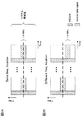
図5は、第2の態様に係る狭帯域の設定例を示す図である。図5Aは、初期設定される狭帯域(NB)の設定例を示す図である。図5Aでは、初期設定される狭帯域が4つである例を説明するが、初期設定される狭帯域の数は、4に限られない。以下では、初期設定される狭帯域を「デフォルト狭帯域」と呼ぶ。 FIG. 5 is a diagram illustrating a setting example of a narrow band according to the second mode. FIG. 5A is a diagram illustrating a setting example of the initially set narrow band (NB). Although FIG. 5A illustrates an example in which the number of initially set narrow bands is four, the number of initially set narrow bands is not limited to four. Hereinafter, the initially set narrow band is referred to as “default narrow band”.
また、デフォルト狭帯域は、MTC端末に予め設定されていてもよいし、MTC端末が接続する無線基地局が形成するセルの識別子(セルID)に基づいて設定されてもよいし、MTC用のシステム情報ブロック(SIB:System Information Block)に基づいて設定されてもよい。 The default narrowband may be set in advance in the MTC terminal, may be set based on a cell identifier (cell ID) formed by a radio base station to which the MTC terminal is connected, It may be set based on a system information block (SIB).
また、図5Aでは、DL用のデフォルト狭帯域のみが示されるが、UL用のデフォルト狭帯域が設定されてもよい。DL用のデフォルト狭帯域は、PDSCHだけでなく、MPDCCHの送信に用いられてもよい。UL用のデフォルト狭帯域は、PUSCHやPUCCHの送信に用いられてもよい。 In FIG. 5A, only the default narrowband for DL is shown, but a default narrowband for UL may be set. The default narrowband for DL may be used for transmission of MPDCCH as well as PDSCH. The default narrowband for UL may be used for transmission of PUSCH and PUCCH.
図5Aに示すように、DL用のデフォルト狭帯域(NB)#1〜#4が設定される場合、MTC端末は、デフォルト狭帯域#1−#4の全てのブラインド復号を行ってMPDCCHで伝送されるDCIを受信してもよいし、一部のブラインド復号を行ってMPDCCHで伝送されるDCIを受信してもよい。ブラインド復号を行うデフォルト狭帯域は、予めMTC端末に設定されてもよいし、MTC用のSIBにより設定されてもよい。
As shown in FIG. 5A, when default narrowband (NB) # 1 to # 4 for DL are set, the MTC terminal performs all blind decoding of default
MTC端末は、DCIにより指定されたPDSCHを介して、複数の狭帯域を示す上位レイヤメッセージ(例えば、RRCメッセージ)を受信する。なお、当該PDSCHは、デフォルト狭帯域#1−#4から選択された一つのデフォルト狭帯域で送信される。当該PDSCH用に選択されたデフォルト狭帯域は、DCIに含まれる情報項目(IE:Information Element)により指示されてもよい。また、当該PDSCHに割り当てられるPRBは、DCIに含まれる他の情報項目(例えば、RAフィールド)により指定されてもよい。 The MTC terminal receives a higher layer message (for example, an RRC message) indicating a plurality of narrow bands via the PDSCH specified by the DCI. The PDSCH is transmitted in one default narrow band selected from default narrow bands # 1- # 4. The default narrowband selected for the PDSCH may be indicated by an information item (IE: Information Element) included in DCI. Further, the PRB assigned to the PDSCH may be specified by another information item (for example, RA field) included in the DCI.
図5Bは、上位レイヤメッセージにより指定される狭帯域(NB)の設定例を示す図である。図5Bに示すように、MTC端末は、デフォルト狭帯域#1〜#4に代えて、上位レイヤメッセージが示す狭帯域#1〜#4を設定する。具体的には、MTC端末は、デフォルト狭帯域#1〜#4を上位レイヤメッセージが示す狭帯域#1〜#4に更新(override)する。
FIG. 5B is a diagram illustrating a setting example of a narrow band (NB) designated by an upper layer message. As illustrated in FIG. 5B, the MTC terminal sets
第2の態様によれば、少なくとも一つのデフォルト狭帯域で送信されるPDSCHにより、複数の狭帯域を示す上位レイヤメッセージを伝送できるので、MTC端末の使用帯域の候補となる複数の狭帯域を上位レイヤシグナリングにより適切に設定できる。 According to the second aspect, since the upper layer message indicating a plurality of narrow bands can be transmitted by the PDSCH transmitted in at least one default narrow band, the plurality of narrow bands that are candidates for the band used by the MTC terminal It can be set appropriately by layer signaling.
(無線通信システム)
以下、本発明の一実施形態に係る無線通信システムの構成について説明する。この無線通信システムでは、上述した本発明の実施形態に係る無線通信方法が適用される。なお、上記の各実施形態に係る無線通信方法は、それぞれ単独で適用されてもよいし、組み合わせて適用されてもよい。ここでは、狭帯域に使用帯域が制限されたユーザ端末としてMTC端末を例示するが、MTC端末に限定されるものではない。
(Wireless communication system)
Hereinafter, the configuration of a wireless communication system according to an embodiment of the present invention will be described. In this wireless communication system, the above-described wireless communication method according to the embodiment of the present invention is applied. In addition, the radio | wireless communication method which concerns on said each embodiment may each be applied independently, and may be applied in combination. Here, an MTC terminal is illustrated as a user terminal whose use band is limited to a narrow band, but is not limited to an MTC terminal.
図6は、本発明の一実施形態に係る無線通信システムの概略構成図である。図6に示す無線通信システム1は、マシンタイプ通信(MTC)システムのネットワークドメインにLTEシステムを採用した一例である。当該無線通信システム1では、LTEシステムのシステム帯域幅を1単位とする複数の基本周波数ブロック(コンポーネントキャリア)を一体としたキャリアアグリゲーション(CA)及び/又はデュアルコネクティビティ(DC)を適用することができる。また、LTEシステムが下りリンク及び上りリンク共に最大20MHzのシステム帯域に設定されるものとするが、この構成に限られない。なお、無線通信システム1は、SUPER 3G、LTE−A(LTE-Advanced)、IMT−Advanced、4G、5G、FRA(Future Radio Access)などと呼ばれてもよい。
FIG. 6 is a schematic configuration diagram of a radio communication system according to an embodiment of the present invention. A
無線通信システム1は、無線基地局10と、無線基地局10に無線接続する複数のユーザ端末20A、20B及び20Cとを含んで構成されている。無線基地局10は、上位局装置30に接続され、上位局装置30を介してコアネットワーク40に接続される。なお、上位局装置30には、例えば、アクセスゲートウェイ装置、無線ネットワークコントローラ(RNC)、モビリティマネジメントエンティティ(MME)などが含まれるが、これに限定されるものではない。
The
複数のユーザ端末20A、20B及び20Cは、セル50において無線基地局10と通信を行うことができる。例えば、ユーザ端末20Aは、LTE(Rel−10まで)又はLTE−Advanced(Rel−10以降も含む)をサポートするユーザ端末(以下、LTE端末)であり、他のユーザ端末20B、20Cは、MTCシステムにおける通信デバイスとなるMTC端末であり、使用帯域がシステム帯域の一部の狭帯域(周波数ブロック)に制限される。以下、特に区別を要しない場合は、ユーザ端末20A、20B及び20Cは単にユーザ端末20と呼ぶ。
The plurality of
なお、MTC端末20B、20Cは、LTE、LTE−Aなどの各種通信方式に対応した端末であり、電気メータ、ガスメータ、自動販売機などの固定通信端末に限らず、車両などの移動通信端末でもよい。また、ユーザ端末20は、直に他のユーザ端末20と通信してもよいし、無線基地局10を介して他のユーザ端末20と通信してもよい。
The MTC terminals 20B and 20C are terminals compatible with various communication methods such as LTE and LTE-A, and are not limited to fixed communication terminals such as electric meters, gas meters, and vending machines, but also mobile communication terminals such as vehicles. Good. Further, the
無線通信システム1においては、無線アクセス方式として、下りリンクについてはOFDMA(直交周波数分割多元接続)が適用され、上りリンクについてはSC−FDMA(シングルキャリア−周波数分割多元接続)が適用される。OFDMAは、周波数帯域を複数の狭い周波数帯域(サブキャリア)に分割し、各サブキャリアにデータをマッピングして通信を行うマルチキャリア伝送方式である。SC−FDMAは、システム帯域幅を端末毎に1つ又は連続したリソースブロックからなる帯域に分割し、複数の端末が互いに異なる帯域を用いることで、端末間の干渉を低減するシングルキャリア伝送方式である。なお、上り及び下りの無線アクセス方式は、これらの組み合わせに限られない。
In the
無線通信システム1では、下りリンクのチャネルとして、各ユーザ端末20で共有される下り共有チャネル(PDSCH:Physical Downlink Shared Channel)、報知チャネル(PBCH:Physical Broadcast Channel)、下りL1/L2制御チャネルなどが用いられる。PDSCHにより、ユーザデータや上位レイヤ制御情報、所定のSIB(System Information Block)が伝送される。また、PBCHにより、MIB(Master Information Block)が伝送される。
In the
下りL1/L2制御チャネルは、PDCCH(Physical Downlink Control Channel)、EPDCCH(Enhanced Physical Downlink Control Channel)、PCFICH(Physical Control Format Indicator Channel)、PHICH(Physical Hybrid-ARQ Indicator Channel)、MPDCCH(Machine type communication Physical Downlink Control Channel)などを含む。 Downlink L1 / L2 control channels are PDCCH (Physical Downlink Control Channel), EPDCCH (Enhanced Physical Downlink Control Channel), PCFICH (Physical Control Format Indicator Channel), PHICH (Physical Hybrid-ARQ Indicator Channel), MPDCCH (Machine type communication Physical Downlink Control Channel).
PDCCHにより、PDSCH及びPUSCHのスケジューリング情報を含む下り制御情報(DCI:Downlink Control Information)などが伝送される。PCFICHにより、PDCCHに用いるOFDMシンボル数が伝送される。PHICHにより、PUSCHに対するHARQの送達確認信号(ACK/NACK)が伝送される。EPDCCH/MPDCCHは、PDSCH(下り共有データチャネル)と周波数分割多重され、PDCCHと同様にDCIなどの伝送に用いられる。MPDCCHは、システム帯域の一部の狭帯域(周波数ブロック)で送信される。 Downlink control information (DCI) including scheduling information of PDSCH and PUSCH is transmitted by PDCCH. The number of OFDM symbols used for PDCCH is transmitted by PCFICH. The HAICH transmission confirmation signal (ACK / NACK) for PUSCH is transmitted by PHICH. EPDCCH / MPDCCH is frequency-division multiplexed with PDSCH (downlink shared data channel), and is used for transmission of DCI and the like, similar to PDCCH. MPDCCH is transmitted in a narrow band (frequency block) of a part of the system band.
無線通信システム1では、上りリンクのチャネルとして、各ユーザ端末20で共有される上り共有チャネル(PUSCH:Physical Uplink Shared Channel)、上り制御チャネル(PUCCH:Physical Uplink Control Channel)、ランダムアクセスチャネル(PRACH:Physical Random Access Channel)などが用いられる。PUSCHにより、ユーザデータや上位レイヤ制御情報が伝送される。また、PUCCHにより、下りリンクの無線品質情報(CQI:Channel Quality Indicator)、送達確認信号などが伝送される。PRACHにより、セルとの接続確立のためのランダムアクセスプリアンブル(RAプリアンブル)が伝送される。
In the
<無線基地局>
図7は、本発明の一実施形態に係る無線基地局の全体構成の一例を示す図である。無線基地局10は、複数の送受信アンテナ101と、アンプ部102と、送受信部103と、ベースバンド信号処理部104と、呼処理部105と、伝送路インターフェース106とを備えている。なお、送受信部103は、送信部及び受信部で構成される。
<Wireless base station>
FIG. 7 is a diagram illustrating an example of an overall configuration of a radio base station according to an embodiment of the present invention. The
下りリンクにより無線基地局10からユーザ端末20に送信されるユーザデータは、上位局装置30から伝送路インターフェース106を介してベースバンド信号処理部104に入力される。
User data transmitted from the
ベースバンド信号処理部104では、ユーザデータに関して、PDCP(Packet Data Convergence Protocol)レイヤの処理、ユーザデータの分割・結合、RLC(Radio Link Control)再送制御などのRLCレイヤの送信処理、MAC(Medium Access Control)再送制御(例えば、HARQ(Hybrid Automatic Repeat reQuest)の送信処理)、スケジューリング、伝送フォーマット選択、チャネル符号化、逆高速フーリエ変換(IFFT:Inverse Fast Fourier Transform)処理、プリコーディング処理などの送信処理が行われて各送受信部103に転送される。また、下り制御信号に関しても、チャネル符号化や逆高速フーリエ変換などの送信処理が行われて、各送受信部103に転送される。
The baseband
送受信部103は、下り信号を受信するとともに、上り信号を送信する。下り信号は、下り制御信号(例えば、PDCCH/EPDCCH/MPDCCH)、下りデータ信号(例えば、PDSCH)、下り参照信号(例えば、CSI−RS(Channel State Information-Reference Signal)、CRS(Cell-specific Reference Signal))、上位レイヤ制御信号などを含む。上り信号は、上り制御信号(例えば、PUCCH)、上りデータ信号(例えば、PUSCH)、上り参照信号(例えば、SRS(Sounding Reference Signal)、DM−RS(DeModulation-Reference Signal))、上位レイヤ制御信号などを含む。
The transmission /
具体的には、送受信部103は、ベースバンド信号処理部104からアンテナ毎にプリコーディングして出力されたベースバンド信号を無線周波数帯に変換して送信する。送受信部103で周波数変換された無線周波数信号は、アンプ部102により増幅され、送受信アンテナ101から送信される。送受信部103は、システム帯域幅(例えば、1コンポーネントキャリア)より制限された狭帯域(周波数ブロック)(例えば、1.4MHz)で、各種信号を送受信することができる。
Specifically, the transmission /
一方、上り信号については、各送受信アンテナ101で受信された無線周波数信号がそれぞれアンプ部102で増幅される。各送受信部103はアンプ部102で増幅された上り信号を受信する。送受信部103は、受信信号をベースバンド信号に周波数変換して、ベースバンド信号処理部104に出力する。
On the other hand, for the uplink signal, the radio frequency signal received by each transmission /
ベースバンド信号処理部104では、入力された上り信号に含まれるユーザデータに対して、高速フーリエ変換(FFT:Fast Fourier Transform)処理、逆離散フーリエ変換(IDFT:Inverse Discrete Fourier Transform)処理、誤り訂正復号、MAC再送制御の受信処理、RLCレイヤ、PDCPレイヤの受信処理がなされ、伝送路インターフェース106を介して上位局装置30に転送される。呼処理部105は、通信チャネルの設定や解放などの呼処理や、無線基地局10の状態管理や、無線リソースの管理を行う。
The baseband
また、送受信部103は、チャネル状態情報(CSI)を受信する。また、送受信部103は、上位レイヤメッセージ(上位レイヤ制御信号)をユーザ端末20に送信する。当該上位レイヤメッセージは、周波数ホッピングされる狭帯域(周波数ブロック)に関する情報(例えば、周波数ホッピングパターン)、MPDCCHを受信(監視)するサブフレーム(M-PDCCH monitoring subframe)に関する情報(例えば、周期、オフセット)、複数の狭帯域を示す情報の少なくとも一つを含んでもよい。
In addition, the transmission /
送受信部103は、本発明に係る技術分野での共通認識に基づいて説明されるトランスミッター/レシーバー、送受信回路又は送受信装置とすることができる。
The transmission /
伝送路インターフェース106は、所定のインターフェースを介して、上位局装置30と信号を送受信する。また、伝送路インターフェース106は、基地局間インターフェース(例えば、CPRI(Common Public Radio Interface)に準拠した光ファイバ、X2インターフェース)を介して隣接無線基地局10と信号を送受信(バックホールシグナリング)してもよい。
The transmission path interface 106 transmits and receives signals to and from the
図8は、本実施形態に係る無線基地局の機能構成の一例を示す図である。なお、図8では、本実施形態における特徴部分の機能ブロックを主に示しており、無線基地局10は、無線通信に必要な他の機能ブロックも有しているものとする。図8に示すように、ベースバンド信号処理部104は、制御部301と、送信信号生成部302と、マッピング部303と、受信信号処理部304と、を備えている。
FIG. 8 is a diagram illustrating an example of a functional configuration of the radio base station according to the present embodiment. Note that FIG. 8 mainly shows functional blocks of characteristic portions in the present embodiment, and the
制御部301は、下りデータ信号(PDSCH)、下り制御信号(PDCCH、EPDCCH及びMPDCCHの少なくとも一つ)のスケジューリング(例えば、リソース割り当て)を制御する。また、システム情報、同期信号や、下り参照信号(CRS、CSI−RS、DM−RSなどの)のスケジューリングの制御も行う。また、上り参照信号、上りデータ信号(PUSCH)、上り制御信号(PUCCH)、PRACHで送信されるランダムアクセスプリアンブルなどのスケジューリングを制御する。
The
制御部301は、各種信号を狭帯域に割り当ててユーザ端末20に対して送信するように、送信信号生成部302及びマッピング部303を制御する。例えば、制御部301は、下りリンクのシステム情報(MIB、SIB)や、下り制御信号(MPDCCH)、下りデータ信号(PDSCH)などを狭帯域で送信するように制御する。
The
また、制御部301は、所定周期のサブフレームで下り制御信号(MPDCCH)を送信するように制御する。具体的には、制御部301は、所定周期のサブフレームにおいて、複数のサブフレームに渡る繰り返しなしで(すなわち、単一のサブフレームで)下り制御信号を送信するように制御する。なお、制御部301は、複数のサブフレームに渡り下り制御信号を繰り返し送信するように制御してもよい。
In addition, the
また、制御部301は、所定周期のサブフレームにおいて、周波数ホッピングされる狭帯域(周波数ブロック)で下り制御信号(MPDCCH)を送信するよう制御してもよい。
In addition, the
また、制御部301は、ユーザ端末20の使用帯域の候補となる複数の狭帯域を決定してもよい。例えば、制御部301は、ユーザ端末20で測定された複数の狭帯域のCSIに基づいて、当該複数の狭帯域を決定してもよい。
Further, the
また、制御部301は、ユーザ端末20で測定された複数の狭帯域のCSIに基づいて、下りデータ信号(PDSCH)を割り当てる狭帯域を決定(選択)してもよい。選択された狭帯域を示す情報は、DCIに含まれ、下り制御信号(MPDCCH)によりユーザ端末20に送信されてもよい。また、選択された狭帯域において下りデータ信号(PDSCH)に割り当てられるPRBを示す情報も、DCIに含まれ、下り制御信号(MPDCCH)によりユーザ端末20に送信されてもよい。
Further, the
制御部301は、本発明に係る技術分野での共通認識に基づいて説明されるコントローラ、制御回路又は制御装置とすることができる。
The
送信信号生成部302は、制御部301からの指示に基づいて、下り信号を生成して、マッピング部303に出力する。例えば、送信信号生成部302は、制御部301からの指示に基づいて、下りデータ信号の割り当て情報を通知する下りグラント(下りアサインメント)及び上りデータ信号の割り当て情報を通知する上りグラントを生成する。
The transmission
また、送信信号生成部302は、制御部301からの指示に基づいて、下り制御信号(MPDCCH)を生成する。また、送信信号生成部302は、制御部301からの指示に基づいて、上位レイヤ制御信号や下りデータ信号を生成する。
Also, the transmission
送信信号生成部302は、本発明に係る技術分野での共通認識に基づいて説明される信号生成器、信号生成回路又は信号生成装置とすることができる。
The transmission
マッピング部303は、制御部301からの指示に基づいて、送信信号生成部302で生成された下り信号を、所定の狭帯域の無線リソース(例えば、最大6リソースブロック)にマッピングして、送受信部103に出力する。マッピング部303は、本発明に係る技術分野での共通認識に基づいて説明されるマッパー、マッピング回路又はマッピング装置とすることができる。
The
受信信号処理部304は、送受信部103から入力された受信信号に対して、受信処理(例えば、デマッピング、復調、復号など)を行う。ここで、受信信号は、例えば、ユーザ端末20から送信される上り信号(上りデータ信号(PUSCH)、上り制御信号(PUCCH)、上り参照信号(SRS、DMRS)、上位レイヤ制御信号など)である。受信信号処理部304は、受信した情報を制御部301に出力する。
The reception
また、受信信号処理部304は、受信した信号を用いて受信電力(例えば、RSRP(Reference Signal Received Power))、受信品質(例えば、RSRQ(Reference Signal Received Quality))やチャネル状態などについて測定してもよい。測定結果は、制御部301に出力されてもよい。
Further, the received
受信信号処理部304は、本発明に係る技術分野での共通認識に基づいて説明される信号処理器、信号処理回路又は信号処理装置、並びに、測定器、測定回路又は測定装置から構成することができる。
The reception
<ユーザ端末>
図9は、本実施形態に係るユーザ端末の全体構成の一例を示す図である。なお、ここでは詳細な説明を省略するが、通常のLTE端末がMTC端末として振る舞うように動作してもよい。ユーザ端末20は、送受信アンテナ201と、アンプ部202と、送受信部203と、ベースバンド信号処理部204と、アプリケーション部205と、を備えている。なお、送受信部203は、送信部及び受信部から構成される。また、ユーザ端末20は、送受信アンテナ201、アンプ部202、送受信部203などを複数備えてもよい。
<User terminal>
FIG. 9 is a diagram illustrating an example of the overall configuration of the user terminal according to the present embodiment. In addition, although detailed description is abbreviate | omitted here, you may operate | move so that a normal LTE terminal may act as a MTC terminal. The
送受信アンテナ201で受信された無線周波数信号は、アンプ部202で増幅される。送受信部203は、アンプ部202で増幅された下り信号(下り制御信号(PDCCH/EPDCCH/MPDCCH)、下りデータ信号(PDSCH)、下り参照信号(CSI−RS、CRSなど)、上位レイヤ制御信号などを含む)を受信する。送受信部203は、受信信号をベースバンド信号に周波数変換して、ベースバンド信号処理部204に出力する。
The radio frequency signal received by the transmission /
また、送受信部203は、ベースバンド信号処理部204から出力された上り信号(上り制御信号(PUCCH)、上りデータ信号(PUSCH)、上り参照信号(DM−RS、SRS)などを含む)を送信する。
Further, the transmission /
ベースバンド信号処理部204は、入力されたベースバンド信号に対して、FFT処理や、誤り訂正復号、再送制御の受信処理などを行う。下りリンクのユーザデータは、アプリケーション部205に転送される。アプリケーション部205は、物理レイヤやMACレイヤより上位のレイヤに関する処理などを行う。また、下りリンクのデータのうち、報知情報もアプリケーション部205に転送される。
The baseband
一方、上りリンクのユーザデータについては、アプリケーション部205からベースバンド信号処理部204に入力される。ベースバンド信号処理部204では、再送制御の送信処理(例えば、HARQの送信処理)や、チャネル符号化、プリコーディング、離散フーリエ変換(DFT:Discrete Fourier Transform)処理、IFFT処理などが行われて送受信部203に転送される。送受信部203は、ベースバンド信号処理部204から出力されたベースバンド信号を無線周波数帯に変換して送信する。送受信部203で周波数変換された無線周波数信号は、アンプ部202により増幅され、送受信アンテナ201から送信される。
On the other hand, uplink user data is input from the
また、送受信部203は、上位レイヤシグナリング又はシステム情報により、所定周期のサブフレーム(MPDCCH monitoring subframe)に関する情報を受信してもよい。当該サブフレームに関する情報には、例えば、周期や、無線フレームの先頭に対するオフセットの少なくとも1つが含まれてもよい。また、送受信部203は、上位レイヤシグナリング又はシステム情報により、周波数ホッピングされる狭帯域に関する周波数ホッピング情報を受信してもよい。また、送受信部203は、後述する測定部405により測定されるCSIを送信する。
Moreover, the transmission /
送受信部203は、本発明に係る技術分野での共通認識に基づいて説明されるトランスミッター/レシーバー、送受信回路又は送受信装置とすることができる。
The transmission /
図10は、本実施形態に係るユーザ端末の機能構成の一例を示す図である。なお、図10においては、本実施形態における特徴部分の機能ブロックを主に示しており、ユーザ端末20は、無線通信に必要な他の機能ブロックも有しているものとする。図10に示すように、ユーザ端末20が有するベースバンド信号処理部204は、制御部401と、送信信号生成部402と、マッピング部403と、受信信号処理部404と、測定部405と、を備えている。
FIG. 10 is a diagram illustrating an example of a functional configuration of the user terminal according to the present embodiment. Note that FIG. 10 mainly shows functional blocks of characteristic portions in the present embodiment, and the
制御部401は、送信信号生成部402及びマッピング部403の制御を行う。制御部401は、無線基地局10から送信された下り制御信号(PDCCH/EPDCCH/MPDCCH)、下りデータ信号(PDSCH)及び上位レイヤ制御信号を、受信信号処理部404から取得する。制御部401は、下り制御信号や、下りデータ信号に対する再送制御の要否を判定した結果などに基づいて、上り制御信号(PUCCH)や上りデータ信号(PUSCH)の生成を制御する。
The
また、制御部401は、所定周期のサブフレーム(MPDCCH monitoring subframe)で下り制御信号(MPDCCH)を受信するように制御する。具体的には、制御部401は、所定周期のサブフレームにおいて、複数のサブフレームに渡る繰り返しなしで(すなわち、単一のサブフレームで)送信される下り制御信号を受信するように制御してもよい。なお、制御部401は、複数のサブフレームに渡り下り制御信号を繰り返し受信してもよい。
In addition, the
また、制御部401は、所定周期のサブフレームにおいて、周波数ホッピングされる狭帯域で、下り制御信号(MPDCCH)を受信するように制御してもよい。上述の通り、周波数ホッピングされる狭帯域は、上位レイヤシグナリング又はシステム情報により無線基地局10から通知されてもよいし、予めユーザ端末20に設定されていてもよい。
Further, the
また、制御部401は、測定部405によるCSIの測定を制御する。具体的には、制御部401は、下り制御信号(MPDCCH)を受信(監視)する所定周期のサブフレームにおいて、周波数ホッピングされる狭帯域(周波数ブロック)のCSIを測定するように制御してもよい。また、制御部401は、上記下り制御信号に測定要求が含まれる場合、上記所定周期のサブフレームにおいて、CSIを測定するよう制御してもよい。
Further, the
また、制御部401は、下り制御信号(MPDCCH)を受信(監視)する所定周期のサブフレームにおいて、下りデータ信号(PDSCH)が割り当てられる場合、当該下りデータ信号が割り当てられる狭帯域のCSIを測定するよう制御してもよい。
In addition, when a downlink data signal (PDSCH) is assigned in a subframe of a predetermined period for receiving (monitoring) the downlink control signal (MPDCCH), the
また、制御部401は、下り制御信号(MPDCCH)を受信(監視)する所定周期のサブフレームにおいて、下りデータ信号(PDSCH)が割り当てられる場合、CSIの測定を中止するよう制御してもよい。
In addition, the
また、制御部401は、下り制御信号(MPDCCH)を受信(監視)する所定周期のサブフレーム以外のサブフレームにおいて、下りデータ信号(PDSCH)が割り当てられる場合、当該下りデータ信号が割り当てられる狭帯域のCSIを測定するよう制御してもよい。
In addition, when a downlink data signal (PDSCH) is assigned in a subframe other than a subframe having a predetermined period for receiving (monitoring) the downlink control signal (MPDCCH), the
また、制御部401は、受信信号処理部404から、複数の狭帯域(周波数ブロック)を示す上位レイヤメッセージ(上位レイヤ制御信号)が入力される場合、初期設定される少なくとも1つの狭帯域に代えて、当該複数の狭帯域を設定(configure)してもよい。
In addition, when an upper layer message (upper layer control signal) indicating a plurality of narrow bands (frequency blocks) is input from the received
制御部401は、本発明に係る技術分野での共通認識に基づいて説明されるコントローラ、制御回路又は制御装置とすることができる。なお、制御部401は、測定部405と合わせて本発明に係る測定部を構成することができる。
The
送信信号生成部402は、制御部401からの指示に基づいて、上り信号を生成して、マッピング部403に出力する。例えば、送信信号生成部402は、制御部401からの指示に基づいて、上り制御情報(UCI)を含む上り制御信号(PUCCH)を生成する。UCIは、送達確認情報(HARQ−ACK)、チャネル状態情報(CSI)及びスケジューリング要求(SR)の少なくとも一つを含んでもよい。また、送信信号生成部402は、制御部401からの指示に基づいて、上り制御情報(UCI)を含む上りデータ信号(PUSCH)を生成してもよい。
The transmission
また、送信信号生成部402は、制御部401からの指示に基づいて上りデータ信号(PUSCH)を生成する。例えば、送信信号生成部402は、無線基地局10から通知される下り制御信号に上りグラントが含まれている場合に、制御部401から上りデータ信号の生成を指示される。
Further, the transmission
送信信号生成部402は、本発明に係る技術分野での共通認識に基づいて説明される信号生成器、信号生成回路又は信号生成装置とすることができる。
The transmission
マッピング部403は、制御部401からの指示に基づいて、送信信号生成部402で生成された上り信号を無線リソース(例えば、最大6PRB)にマッピングして、送受信部203へ出力する。マッピング部403は、本発明に係る技術分野での共通認識に基づいて説明されるマッパー、マッピング回路又はマッピング装置とすることができる。
Based on an instruction from the
受信信号処理部404は、送受信部203から入力された受信信号に対して、受信処理(例えば、デマッピング、復調、復号など)を行う。ここで、受信信号は、例えば、無線基地局10から送信される下り信号(下り制御信号(PDCCH/EPDCCH/MPDCCH)、下りデータ信号(PDSCH)など)、上位レイヤ制御信号などである。
The reception
受信信号処理部404は、受信した情報を制御部401に出力する。受信信号処理部404は、例えば、報知情報、システム情報、RRCシグナリング、DCIなどを、制御部401に出力する。また、受信信号処理部404は、受信信号や、受信処理後の信号を、測定部405に出力する。
The reception
受信信号処理部404は、本発明に係る技術分野での共通認識に基づいて説明される信号処理器、信号処理回路又は信号処理装置とすることができる。また、受信信号処理部404は、本発明に係る受信部を構成することができる。
The reception
測定部405は、制御部401からの指示に基づいて、CSIを測定する。CSIは、ランク識別子(RI)、チャネル品質識別子(CQI)、プリコーディングマトリクス識別子(PMI)の少なくとも一つを含む。また、測定部405は、受信した信号を用いて受信電力(RSRP)、受信品質(RSRQ)などについて測定してもよい。なお、処理結果や測定結果は、制御部401に出力されてもよい。
The
測定部405は、本発明に係る技術分野での共通認識に基づいて説明される測定器、測定回路又は測定装置とすることができる。
The measuring
なお、上記実施形態の説明に用いたブロック図は、機能単位のブロックを示している。これらの機能ブロック(構成部)は、ハードウェア及びソフトウェアの任意の組み合わせによって実現される。また、各機能ブロックの実現手段は特に限定されない。すなわち、各機能ブロックは、物理的に結合した1つの装置により実現されてもよいし、物理的に分離した2つ以上の装置を有線又は無線で接続し、これら複数の装置により実現されてもよい。 In addition, the block diagram used for description of the said embodiment has shown the block of the functional unit. These functional blocks (components) are realized by any combination of hardware and software. Further, the means for realizing each functional block is not particularly limited. That is, each functional block may be realized by one physically coupled device, or may be realized by two or more physically separated devices connected by wire or wirelessly and by a plurality of these devices. Good.
例えば、無線基地局10やユーザ端末20の各機能の一部又は全ては、ASIC(Application Specific Integrated Circuit)、PLD(Programmable Logic Device)、FPGA(Field Programmable Gate Array)などのハードウェアを用いて実現されても良い。また、無線基地局10やユーザ端末20は、プロセッサ(CPU:Central Processing Unit)と、ネットワーク接続用の通信インターフェースと、メモリと、プログラムを保持したコンピュータ読み取り可能な記憶媒体と、を含むコンピュータ装置によって実現されてもよい。つまり、本発明の一実施形態に係る無線基地局、ユーザ端末などは、本発明に係る無線通信方法の処理を行うコンピュータとして機能してもよい。
For example, some or all of the functions of the
ここで、プロセッサやメモリなどは情報を通信するためのバスで接続される。また、コンピュータ読み取り可能な記録媒体は、例えば、フレキシブルディスク、光磁気ディスク、ROM(Read Only Memory)、EPROM(Erasable Programmable ROM)、CD−ROM(Compact Disc−ROM)、RAM(Random Access Memory)、ハードディスクなどの記憶媒体である。また、プログラムは、電気通信回線を介してネットワークから送信されても良い。また、無線基地局10やユーザ端末20は、入力キーなどの入力装置や、ディスプレイなどの出力装置を含んでいてもよい。
Here, the processor, the memory, and the like are connected by a bus for communicating information. The computer-readable recording medium includes, for example, a flexible disk, a magneto-optical disk, a ROM (Read Only Memory), an EPROM (Erasable Programmable ROM), a CD-ROM (Compact Disc-ROM), a RAM (Random Access Memory), A storage medium such as a hard disk. In addition, the program may be transmitted from a network via a telecommunication line. The
無線基地局10及びユーザ端末20の機能構成は、上述のハードウェアによって実現されてもよいし、プロセッサによって実行されるソフトウェアモジュールによって実現されてもよいし、両者の組み合わせによって実現されてもよい。プロセッサは、オペレーティングシステムを動作させてユーザ端末20の全体を制御する。また、プロセッサは、記憶媒体からプログラム、ソフトウェアモジュールやデータをメモリに読み出し、これらに従って各種の処理を実行する。
The functional configurations of the
ここで、当該プログラムは、上記の各実施形態で説明した各動作を、コンピュータに実行させるプログラムであれば良い。例えば、ユーザ端末20の制御部401は、メモリに格納され、プロセッサで動作する制御プログラムによって実現されてもよく、他の機能ブロックについても同様に実現されてもよい。
Here, the program may be a program that causes a computer to execute the operations described in the above embodiments. For example, the
また、ソフトウェア、命令などは、伝送媒体を介して送受信されてもよい。例えば、ソフトウェアが、同軸ケーブル、光ファイバケーブル、ツイストペア及びデジタル加入者回線(DSL)などの有線技術及び/又は赤外線、無線及びマイクロ波などの無線技術を使用してウェブサイト、サーバ、又は他のリモートソースから送信される場合、これらの有線技術及び/又は無線技術は、伝送媒体の定義内に含まれる。 Also, software, instructions, etc. may be transmitted / received via a transmission medium. For example, software may use websites, servers, or other devices using wired technology such as coaxial cable, fiber optic cable, twisted pair and digital subscriber line (DSL) and / or wireless technology such as infrared, wireless and microwave. When transmitted from a remote source, these wired and / or wireless technologies are included within the definition of transmission media.
なお、本明細書で説明した用語及び/又は本明細書の理解に必要な用語については、同一の又は類似する意味を有する用語と置き換えてもよい。例えば、チャネル及び/又はシンボルは信号(シグナリング)であってもよい。また、信号はメッセージであってもよい。また、コンポーネントキャリア(CC)は、キャリア周波数、セルなどと呼ばれてもよい。 Note that the terms described in this specification and / or terms necessary for understanding this specification may be replaced with terms having the same or similar meaning. For example, the channel and / or symbol may be a signal (signaling). The signal may be a message. Further, the component carrier (CC) may be called a carrier frequency, a cell, or the like.
また、本明細書で説明した情報、パラメータなどは、絶対値で表されてもよいし、所定の値からの相対値で表されてもよいし、対応する別の情報で表されてもよい。例えば、無線リソースはインデックスで指示されるものであってもよい。 In addition, information, parameters, and the like described in this specification may be represented by absolute values, may be represented by relative values from a predetermined value, or may be represented by other corresponding information. . For example, the radio resource may be indicated by an index.
本明細書で説明した情報、信号などは、様々な異なる技術のいずれかを使用して表されてもよい。例えば、上記の説明全体に渡って言及され得るデータ、命令、コマンド、情報、信号、ビット、シンボル、チップなどは、電圧、電流、電磁波、磁界若しくは磁性粒子、光場若しくは光子、又はこれらの任意の組み合わせによって表されてもよい。 Information, signals, etc. described herein may be represented using any of a variety of different technologies. For example, data, commands, commands, information, signals, bits, symbols, chips, etc. that may be referred to throughout the above description are voltages, currents, electromagnetic waves, magnetic fields or magnetic particles, light fields or photons, or any of these May be represented by a combination of
本明細書で説明した各態様/実施形態は単独で用いてもよいし、組み合わせて用いてもよいし、実行に伴って切り替えて用いてもよい。また、所定の情報の通知(例えば、「Xであること」の通知)は、明示的に行うものに限られず、暗黙的に(例えば、当該所定の情報の通知を行わないことによって)行われてもよい。 Each aspect / embodiment described in this specification may be used independently, may be used in combination, or may be switched according to execution. In addition, notification of predetermined information (for example, notification of being “X”) is not limited to explicitly performed, but is performed implicitly (for example, by not performing notification of the predetermined information). May be.
情報の通知は、本明細書で説明した態様/実施形態に限られず、他の方法で行われてもよい。例えば、情報の通知は、物理レイヤシグナリング(例えば、DCI(Downlink Control Information)、UCI(Uplink Control Information))、上位レイヤシグナリング(例えば、RRC(Radio Resource Control)シグナリング、MAC(Medium Access Control)シグナリング、報知情報(MIB(Master Information Block)、SIB(System Information Block)))、その他の信号又はこれらの組み合わせによって実施されてもよい。また、RRCシグナリングは、RRCメッセージと呼ばれてもよく、例えば、RRC接続セットアップ(RRCConnectionSetup)メッセージ、RRC接続再構成(RRCConnectionReconfiguration)メッセージなどであってもよい。 The notification of information is not limited to the aspect / embodiment described in the present specification, and may be performed by other methods. For example, notification of information includes physical layer signaling (for example, DCI (Downlink Control Information), UCI (Uplink Control Information)), upper layer signaling (for example, RRC (Radio Resource Control) signaling, MAC (Medium Access Control) signaling), It may be implemented by broadcast information (MIB (Master Information Block), SIB (System Information Block))), other signals, or a combination thereof. Further, the RRC signaling may be referred to as an RRC message, and may be, for example, an RRC connection setup (RRCConnectionSetup) message, an RRC connection reconfiguration (RRCConnectionReconfiguration) message, or the like.
本明細書で説明した各態様/実施形態は、LTE(Long Term Evolution)、LTE−A(LTE-Advanced)、SUPER 3G、IMT−Advanced、4G、5G、FRA(Future Radio Access)、CDMA2000、UMB(Ultra Mobile Broadband)、IEEE 802.11(Wi−Fi)、IEEE 802.16(WiMAX)、IEEE 802.20、UWB(Ultra-WideBand)、Bluetooth(登録商標)、その他の適切なシステムを利用するシステム及び/又はこれらに基づいて拡張された次世代システムに適用されてもよい。 Each aspect / embodiment described herein includes LTE (Long Term Evolution), LTE-A (LTE-Advanced), SUPER 3G, IMT-Advanced, 4G, 5G, Future Radio Access (FRA), CDMA2000, UMB. (Ultra Mobile Broadband), IEEE 802.11 (Wi-Fi), IEEE 802.16 (WiMAX), IEEE 802.20, UWB (Ultra-WideBand), Bluetooth (registered trademark), and other suitable systems The present invention may be applied to a system and / or a next-generation system extended based on these systems.
本明細書で説明した各態様/実施形態の処理手順、シーケンス、フローチャートなどは、矛盾の無い限り、順序を入れ替えてもよい。例えば、本明細書で説明した方法については、例示的な順序で様々なステップの要素を提示しており、提示した特定の順序に限定されない。 As long as there is no contradiction, the order of the processing procedures, sequences, flowcharts, and the like of each aspect / embodiment described in this specification may be changed. For example, the methods described herein present the elements of the various steps in an exemplary order and are not limited to the specific order presented.
以上、本発明について詳細に説明したが、当業者にとっては、本発明が本明細書中に説明した実施形態に限定されるものではないということは明らかである。本発明は、特許請求の範囲の記載により定まる本発明の趣旨及び範囲を逸脱することなく修正及び変更態様として実施することができる。したがって、本明細書の記載は、例示説明を目的とするものであり、本発明に対して何ら制限的な意味を有するものではない。 Although the present invention has been described in detail above, it will be apparent to those skilled in the art that the present invention is not limited to the embodiments described herein. The present invention can be implemented as modified and changed modes without departing from the spirit and scope of the present invention defined by the description of the scope of claims. Therefore, the description of the present specification is for illustrative purposes and does not have any limiting meaning to the present invention.
1 無線通信システム
10 無線基地局
20 ユーザ端末
101 送受信アンテナ
102 アンプ部
103 送受信部
104 ベースバンド信号処理部
105 呼処理部
106 伝送路インターフェース
201 送受信アンテナ
202 アンプ部
203 送受信部
204 ベースバンド信号処理部
205 アプリケーション部
301、401 制御部
302、402 送信信号生成部
303、403 マッピング部
304、404 受信信号処理部
405 測定部
DESCRIPTION OF
Claims (6)
周波数ホッピングされる狭帯域で下り制御チャネルを所定周期のサブフレームで監視して、下り制御情報を受信する受信部と、
前記所定周期のサブフレームにおいて前記狭帯域でチャネル状態情報(CSI)を測定する測定部と、
前記下り制御情報に含まれる報告要求に基づいて、前記CSIを送信する送信部と、を具備し、
前記測定部は、前記所定周期のサブフレームで下りデータチャネルが割り当てられる場合、前記狭帯域での前記CSIの測定を中止することを特徴とするユーザ端末。 A user terminal whose use band is limited to a narrow part of the system band,
A receiving unit that receives downlink control information by monitoring a downlink control channel in a subband of a predetermined period in a narrow band to be frequency hopped;
A measurement unit that measures channel state information (CSI) in the narrowband in the subframe of the predetermined period;
A transmission unit that transmits the CSI based on a report request included in the downlink control information,
The user equipment characterized in that the measurement unit stops measuring the CSI in the narrowband when a downlink data channel is allocated in a subframe of the predetermined period.
前記ユーザ端末は、周波数ホッピングされる狭帯域で下り制御チャネルを所定周期のサブフレームで監視して、下り制御情報を受信する工程と、前記所定周期のサブフレームにおいて前記狭帯域でチャネル状態情報(CSI)を測定する工程と、前記下り制御情報に含まれる報告要求に基づいて、前記CSIを送信する工程と、を有し、
前記ユーザ端末は、前記所定周期のサブフレームで下りデータチャネルが割り当てられる場合、前記狭帯域での前記CSIの測定を中止することを特徴とする無線通信方法。 A wireless communication method in which a wireless base station communicates with a user terminal whose use band is limited to a narrow part of a system band,
The user terminal monitors a downlink control channel in a subframe with a predetermined period in a narrow band to be frequency hopped, receives downlink control information, and channel state information (in the narrow band in the subframe with the predetermined period) ( Measuring CSI), and transmitting the CSI based on a report request included in the downlink control information,
The wireless communication method, wherein the user terminal stops measuring the CSI in the narrow band when a downlink data channel is allocated in the subframe of the predetermined period.
Priority Applications (2)
| Application Number | Priority Date | Filing Date | Title |
|---|---|---|---|
| JP2015159945A JP6153574B2 (en) | 2015-08-13 | 2015-08-13 | User terminal, radio base station, and radio communication method |
| PCT/JP2016/073773 WO2017026547A1 (en) | 2015-08-13 | 2016-08-12 | User terminal, wireless base station, and wireless communication method |
Applications Claiming Priority (1)
| Application Number | Priority Date | Filing Date | Title |
|---|---|---|---|
| JP2015159945A JP6153574B2 (en) | 2015-08-13 | 2015-08-13 | User terminal, radio base station, and radio communication method |
Publications (2)
| Publication Number | Publication Date |
|---|---|
| JP2017038320A JP2017038320A (en) | 2017-02-16 |
| JP6153574B2 true JP6153574B2 (en) | 2017-06-28 |
Family
ID=57983569
Family Applications (1)
| Application Number | Title | Priority Date | Filing Date |
|---|---|---|---|
| JP2015159945A Expired - Fee Related JP6153574B2 (en) | 2015-08-13 | 2015-08-13 | User terminal, radio base station, and radio communication method |
Country Status (2)
| Country | Link |
|---|---|
| JP (1) | JP6153574B2 (en) |
| WO (1) | WO2017026547A1 (en) |
Families Citing this family (8)
| Publication number | Priority date | Publication date | Assignee | Title |
|---|---|---|---|---|
| US10182364B2 (en) * | 2016-04-01 | 2019-01-15 | Qualcomm Incorporated | Performing a channel state information measurement in an enhanced machine-type communication |
| WO2018209544A1 (en) * | 2017-05-16 | 2018-11-22 | Qualcomm Incorporated | Techniques and apparatuses for sub-physical resource block resource allocation for machine type communication |
| CN110999484B (en) * | 2017-06-08 | 2024-03-12 | 株式会社Ntt都科摩 | Terminal, wireless communication method, base station and system |
| EP3703413B1 (en) * | 2017-10-23 | 2023-08-23 | NTT DoCoMo, Inc. | User terminal and radio communication method |
| US11444676B2 (en) * | 2017-12-27 | 2022-09-13 | Ntt Docomo, Inc. | User terminal and radio communication method |
| EP3751913A4 (en) * | 2018-02-09 | 2021-08-18 | Ntt Docomo, Inc. | User equipment |
| WO2019159243A1 (en) * | 2018-02-14 | 2019-08-22 | 株式会社Nttドコモ | User terminal and wireless communication method |
| WO2020031391A1 (en) * | 2018-08-10 | 2020-02-13 | 株式会社Nttドコモ | User equipment and radio communication method |
-
2015
- 2015-08-13 JP JP2015159945A patent/JP6153574B2/en not_active Expired - Fee Related
-
2016
- 2016-08-12 WO PCT/JP2016/073773 patent/WO2017026547A1/en active Application Filing
Also Published As
| Publication number | Publication date |
|---|---|
| WO2017026547A1 (en) | 2017-02-16 |
| JP2017038320A (en) | 2017-02-16 |
Similar Documents
| Publication | Publication Date | Title |
|---|---|---|
| JP6153575B2 (en) | User terminal, radio base station, and radio communication method | |
| US10555280B2 (en) | User terminal, radio base station and radio communication method | |
| JP6779212B2 (en) | User terminal, wireless base station and wireless communication method | |
| JP6093827B1 (en) | User terminal, radio base station, and radio communication method | |
| WO2017078128A1 (en) | User terminal, radio base station and radio communication method | |
| JP6472463B2 (en) | Wireless base station, user terminal, and wireless communication method | |
| JP6153574B2 (en) | User terminal, radio base station, and radio communication method | |
| WO2017135419A1 (en) | User terminal, wireless base station, and wireless communication method | |
| US11930501B2 (en) | Terminal, communication method, base station, and system for receiving synchronization and/or broadcast signals in a given transmission time interval | |
| WO2017026513A1 (en) | User terminal, wireless base station, wireless communication method, and wireless communication system | |
| WO2017033841A1 (en) | User terminal, wireless base station, and wireless communication method | |
| JP6163181B2 (en) | User terminal, radio base station, and radio communication method | |
| WO2016182050A1 (en) | User terminal, wireless base station, wireless communication system, and wireless communication method | |
| WO2017078129A1 (en) | User terminal, radio base station and radio communication method | |
| CN107926010B (en) | User terminal, radio base station, and radio communication method | |
| WO2016121776A1 (en) | User terminal and radio communication method | |
| JP2018046589A (en) | User terminal, radio base station and radio communication method | |
| WO2017150448A1 (en) | User terminal, wireless base station and wireless communication method |
Legal Events
| Date | Code | Title | Description |
|---|---|---|---|
| A521 | Request for written amendment filed |
Free format text: JAPANESE INTERMEDIATE CODE: A523 Effective date: 20161212 |
|
| A131 | Notification of reasons for refusal |
Free format text: JAPANESE INTERMEDIATE CODE: A131 Effective date: 20170328 |
|
| A521 | Request for written amendment filed |
Free format text: JAPANESE INTERMEDIATE CODE: A523 Effective date: 20170414 |
|
| TRDD | Decision of grant or rejection written | ||
| A01 | Written decision to grant a patent or to grant a registration (utility model) |
Free format text: JAPANESE INTERMEDIATE CODE: A01 Effective date: 20170502 |
|
| A61 | First payment of annual fees (during grant procedure) |
Free format text: JAPANESE INTERMEDIATE CODE: A61 Effective date: 20170530 |
|
| R150 | Certificate of patent or registration of utility model |
Ref document number: 6153574 Country of ref document: JP Free format text: JAPANESE INTERMEDIATE CODE: R150 |
|
| LAPS | Cancellation because of no payment of annual fees |