WO2017077697A1 - 蓄電装置用電極板及びそれを備える蓄電装置 - Google Patents
蓄電装置用電極板及びそれを備える蓄電装置 Download PDFInfo
- Publication number
- WO2017077697A1 WO2017077697A1 PCT/JP2016/004718 JP2016004718W WO2017077697A1 WO 2017077697 A1 WO2017077697 A1 WO 2017077697A1 JP 2016004718 W JP2016004718 W JP 2016004718W WO 2017077697 A1 WO2017077697 A1 WO 2017077697A1
- Authority
- WO
- WIPO (PCT)
- Prior art keywords
- positive electrode
- electrode plate
- current collector
- power storage
- mixture layer
- Prior art date
- Legal status (The legal status is an assumption and is not a legal conclusion. Google has not performed a legal analysis and makes no representation as to the accuracy of the status listed.)
- Ceased
Links
Images

Classifications
-
- H—ELECTRICITY
- H01—ELECTRIC ELEMENTS
- H01G—CAPACITORS; CAPACITORS, RECTIFIERS, DETECTORS, SWITCHING DEVICES, LIGHT-SENSITIVE OR TEMPERATURE-SENSITIVE DEVICES OF THE ELECTROLYTIC TYPE
- H01G11/00—Hybrid capacitors, i.e. capacitors having different positive and negative electrodes; Electric double-layer [EDL] capacitors; Processes for the manufacture thereof or of parts thereof
- H01G11/22—Electrodes
-
- H—ELECTRICITY
- H01—ELECTRIC ELEMENTS
- H01M—PROCESSES OR MEANS, e.g. BATTERIES, FOR THE DIRECT CONVERSION OF CHEMICAL ENERGY INTO ELECTRICAL ENERGY
- H01M4/00—Electrodes
- H01M4/02—Electrodes composed of, or comprising, active material
-
- H—ELECTRICITY
- H01—ELECTRIC ELEMENTS
- H01M—PROCESSES OR MEANS, e.g. BATTERIES, FOR THE DIRECT CONVERSION OF CHEMICAL ENERGY INTO ELECTRICAL ENERGY
- H01M4/00—Electrodes
- H01M4/02—Electrodes composed of, or comprising, active material
- H01M4/13—Electrodes for accumulators with non-aqueous electrolyte, e.g. for lithium-accumulators; Processes of manufacture thereof
-
- Y—GENERAL TAGGING OF NEW TECHNOLOGICAL DEVELOPMENTS; GENERAL TAGGING OF CROSS-SECTIONAL TECHNOLOGIES SPANNING OVER SEVERAL SECTIONS OF THE IPC; TECHNICAL SUBJECTS COVERED BY FORMER USPC CROSS-REFERENCE ART COLLECTIONS [XRACs] AND DIGESTS
- Y02—TECHNOLOGIES OR APPLICATIONS FOR MITIGATION OR ADAPTATION AGAINST CLIMATE CHANGE
- Y02E—REDUCTION OF GREENHOUSE GAS [GHG] EMISSIONS, RELATED TO ENERGY GENERATION, TRANSMISSION OR DISTRIBUTION
- Y02E60/00—Enabling technologies; Technologies with a potential or indirect contribution to GHG emissions mitigation
- Y02E60/10—Energy storage using batteries
Definitions
- the present disclosure relates to an electrode plate for a power storage device and a power storage device including the same.
- Patent Document 2 proposes a coating apparatus that can reduce the area of the plain portion without requiring peeling.
- This coating apparatus includes a plurality of nozzles. The discharge ports of the plurality of nozzles are arranged so as not to overlap each other when viewed from the length direction of the positive electrode current collector.
- the rectangular solid portion is moved in the width direction of the positive electrode current collector by appropriately discharging or stopping the positive electrode mixture slurry from each nozzle while running the positive electrode current collector at a constant speed. It is formed only in part, not in whole.
- the uncoated region is reduced, so that the capacity of the battery can be increased.
- the positive electrode material mixture layer is easily peeled off starting from corners of a rectangular plain portion.
- An object of the present disclosure is to provide an electrode plate for a power storage device that has a high capacity and in which peeling of the mixture layer is suppressed, and a power storage device including the electrode plate.
- An electrode plate for a power storage device of the present disclosure includes a substantially rectangular current collector, and a mixture layer that is provided on at least one surface of the current collector and includes an active material, and the surface has a mixture layer.
- a matching outer edge, two width-extending edges extending along the width direction of the current collector from each of both ends of the outer edge, and each end of the two width-extending edges It has a substantially straight inner edge to be connected, and the inner edge is connected to the end of one of the two widthwise extending edges via a curved portion, and the two widthwise extending edges The inner edge is connected to the end of the other extending edge in the width direction among the existing edges via a curved portion or directly connected thereto.
- the capacity can be increased and peeling of the mixture layer can be suppressed.
- FIG. 1 is a diagram illustrating a structure of a nonaqueous electrolyte secondary battery according to an embodiment of the present disclosure.
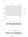
- 2A is a plan view of the positive electrode plate
- FIG. 2B is a cross-sectional view taken along the line AA in FIG. 2A
- FIG. 2C is a cross-sectional view taken along the line B-- in FIG. It is B line sectional drawing.
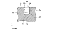
- FIG. 3 is an enlarged view of the periphery of the uncoated portion of the positive electrode plate in FIG.
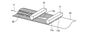
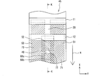
- FIG. 4 is a schematic view showing an outline of a coating process of the positive electrode mixture slurry onto the positive electrode current collector.
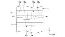
- FIG. 5 is a schematic diagram showing the relative position of the discharge nozzle with respect to the positive electrode current collector as viewed from above the surface of the positive electrode current collector.
- FIG. 6 is a schematic view showing a plurality of ejection regions extending in the length direction on the positive electrode current collector.
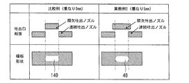
- FIG. 7 is a diagram comparing the positive electrode plate shape of Example 2 and the positive electrode plate shape of the comparative example.
- FIG. 1 is a diagram illustrating a structure of a nonaqueous electrolyte secondary battery according to an embodiment of the present disclosure.
- the nonaqueous electrolyte secondary battery 10 includes a positive electrode plate 1, a positive electrode lead 2, a negative electrode plate 3, a negative electrode lead 4, a separator 5, a battery case 6, a gasket 7, a positive electrode lid 8, and a sealing plate 9.
- the positive electrode plate 1 and the negative electrode plate 3 are wound through a separator 5 and are accommodated in a cylindrical battery case 6 together with an electrolytic solution.
- the opening of the battery case 6 is sealed with a sealing plate 9 via a gasket 7, and the inside of the battery case 6 is sealed.
- the positive electrode plate 1 is connected to the positive electrode lid 8 disposed on the sealing plate 9 by the positive electrode lead 2, and the positive electrode lid 8 serves as a positive electrode terminal.
- the negative electrode plate 3 is connected to the battery case 6 by a negative electrode lead 4, and the battery case 6 serves as a negative electrode terminal.
- the positive electrode plate 1 is manufactured as follows. A paste-like positive electrode mixture slurry is generated by mixing a conductive agent, a binder, or the like with the positive electrode active material. Thereafter, the positive electrode mixture slurry is applied onto a hoop-shaped positive electrode current collector formed of a metal foil such as aluminum to form a positive electrode mixture layer. Next, the positive electrode mixture layer is dried and compressed. Finally, the positive electrode plate 1 is produced by cutting the positive electrode current collector provided with the positive electrode mixture layer into a predetermined size.
- the negative electrode plate 3 is manufactured as follows. A paste-like negative electrode mixture slurry is generated by mixing a conductive agent, a binder, or the like with the negative electrode active material. Thereafter, the negative electrode mixture slurry is applied onto a hoop-shaped negative electrode current collector formed of a metal foil such as copper to form a negative electrode mixture layer. Next, the negative electrode mixture layer is dried and compressed. Finally, the negative electrode current collector provided with the negative electrode mixture layer is cut into a predetermined size to produce the negative electrode plate 3.
- the positive electrode plate 1 and the negative electrode plate 3 each have a plain portion where the mixture slurry is not applied at a predetermined position.
- the positive electrode lead 2 and the negative electrode lead 4 are joined to the plain portions of the positive electrode plate 1 and the negative electrode plate 3, respectively.
- each of the above-mentioned plain parts constitutes a lead connection part.
- FIG. 2 shows the structure of the positive electrode plate 1. Specifically, FIG. 2 (a) is a plan view of the positive electrode plate 1, FIG. 2 (b) is a cross-sectional view taken along the line AA of FIG. 2 (a), and FIG. 2 (c) is FIG. FIG. The line BB in FIG. 2A crosses the plain portion 40.
- the positive electrode plate 1 has a substantially rectangular planar shape, and has a plain portion 40 at one end portion in the width direction Y at the center portion in the length direction X. If the plain portion 40 is provided at one end portion in the width direction Y of the positive electrode plate 1, the plain portion 40 can be provided at a position other than the central portion in the length direction X.
- the positive electrode plate 1 includes a positive electrode current collector 20 and a positive electrode mixture layer 30 provided on both surfaces of the positive electrode current collector 20.
- the positive electrode mixture layer 30 is provided on the surfaces on both sides of the positive electrode current collector 20, it is preferable to provide the plain portion 40 so as to overlap the front and back of the positive electrode current collector 20 as shown in FIG.
- the positive electrode mixture layer may be provided only on one surface of the positive electrode current collector.
- FIG. 3 is an enlarged view around the plain portion 40 of the positive electrode plate 1 in FIG.
- the outer edge of the plain portion 40 includes a pair of width direction extending edges 40 a and 40 b extending in the width direction Y and a pair of length direction extending edges extending in the substantially length direction X. 40c, 40d.
- the lengthwise extending edge 40d coincides with a part of the outer edge extending along the length direction X of the positive electrode current collector 20, and constitutes an outer edge.
- the lengthwise extending edge 40c is connected to the respective ends of the widthwise extending edges 40a and 40b via curved portions, and constitutes an inner edge (hereinafter referred to as an outer edge 40d and an inner edge 40c).
- Curved portions connecting the width direction extending edges 40a, 40b and the inner edge 40c occupy the inner corners 40e, 40f. It is preferable that a curved portion is interposed between the width direction extending edges 40a and 40b and the inner edge 40c. However, one of the width direction extending edges 40a and 40b and the inner edge 40c are not directly connected to the curved portion. It can be connected to the inner edge 40c.
- the inner edge 40c and the outer edge 40d are preferably arranged so as to be parallel to each other, but the extending direction of the inner edge 40c is not limited to the substantially length direction X. On the other hand, the extending direction of the width direction extending edges 40a and 40b is preferably substantially the width direction Y.
- the curved portions of the inner corner portion 40e and the inner corner portion 40f preferably have a shape that protrudes outward from the plain portion 40, and the shape is more preferably an R shape.
- the positive electrode mixture layer 30 may have a plurality of trailing portions 30a extending in the substantially length direction X from one width direction extending edge 40a. When it has the tailing part 30a, the tailing part 30a is disregarded and the width direction extending edge 40a is specified.
- FIG. 4 is a schematic diagram showing an outline of a coating process of the positive electrode mixture slurry onto the hoop-shaped positive electrode current collector 20.
- the hoop-shaped positive electrode current collector 20 is unwound by a driving roll (not shown). In this way, the positive electrode current collector 20 is caused to travel at a constant speed in the direction indicated by the arrow A under the first and second discharge portions 11 and 12.
- the positive electrode mixture layer 30 is formed on the positive electrode current collector 20 by discharging the positive electrode mixture slurry from the first and second discharge portions 11 and 12 toward the positive electrode current collector 20.
- the first discharge unit 11 is provided with discharge nozzles 11a and 11b
- the second discharge unit 12 is provided with a discharge nozzle 12a.
- FIG. 5 is a schematic diagram showing the relative positions of the discharge nozzles 11a, 11b, and 12a with respect to the positive electrode current collector 20 when viewed from above the front surface 55 of the positive electrode current collector 20.
- the first discharge part 11 is located at a distance from the second discharge part 12 in the length direction of the positive electrode current collector 20.
- the length direction X of the positive electrode current collector 20 coincides with the length direction X (see FIG. 2) of the positive electrode plate 1
- the width direction Y of the positive electrode current collector 20 coincides with the width direction Y of the positive electrode plate 1.
- the discharge nozzles 11a, 11b, and 12a have rectangular discharge ports 18a, 18b, and 19a, respectively.
- the discharge ports 18 a, 18 b, 19 a extend in the width direction Y of the positive electrode current collector 20.
- the length direction of the discharge ports 18 a, 18 b, 19 a coincides with the width direction Y of the positive electrode current collector 20, and the width direction of the discharge ports 18 a, 18 b, 19 a coincides with the length direction X of the positive electrode current collector 20.
- the dimension in the width direction of the discharge port 18a of the discharge nozzle 11a is the same as the dimension in the width direction of the discharge port 18b of the discharge nozzle 11b.
- the discharge port 18 a and the discharge port 18 b exist at the same position with respect to the length direction of the strip-shaped positive electrode current collector 20.
- the discharge port 18a is located at an interval in the length direction X of the positive electrode current collector 20 with respect to the discharge port 19a of the discharge nozzle 12a.
- Each of the discharge nozzles 11a, 11b, and 12a has a control valve.
- the control valves of the discharge nozzles 11a, 11b, and 12a can be controlled independently of each other.
- the supply and stop of the positive electrode mixture slurry to the discharge nozzles 11a, 11b, and 12a are controlled using each control valve.
- the positive electrode mixture slurry is intermittently discharged from the discharge nozzle 12a by periodically repeating the supply and stop of the positive electrode mixture slurry to the discharge nozzle 12a.
- the plain part 40 is provided in the positive electrode current collector 20.
- the positive electrode mixture slurry discharged from the discharge port 18 a is applied to one side region in the width direction Y of the positive electrode current collector 20, and the positive electrode mixture slurry discharged from the discharge port 18 b is applied to the width of the positive electrode current collector 20. It is applied to the other side region in the direction Y.
- the positive electrode mixture slurry discharged from the discharge port 19 a is applied to the central region in the width direction Y of the positive electrode current collector 20.
- f 1 [mm] when viewed from the length direction X, a part of the discharge port 19a overlaps a part of the discharge port 18a.
- the amount of overlap is defined as f 1 [mm].
- a part of the discharge port 19a overlaps a part of the discharge port 18b.
- the amount of overlap is set to f 2 [mm].
- the discharge port 19a has a region that does not overlap either the discharge port 18a or the discharge port 18b.
- FIG. 6 is a schematic diagram showing the discharge regions 50, 51, 52 on the positive electrode current collector 20 corresponding to the positive electrode mixture slurry discharged from each of the discharge nozzles 11a, 11b, 12a.
- the discharge regions 50, 51, 52 are set so as to form the overlapping portions 60 a, 60 b and the non-overlapping portions 70, 71, 72.
- the lengths of the overlapping portions 60a and 60b in the width direction Y are equal to the overlapping amounts f 1 [mm] and f 2 [mm], respectively.
- the first discharge section 11 is configured such that both ends in the width direction Y of the discharge ports 18a, 18b, 19a coincide with both ends in the width direction Y of the discharge areas 50, 51, 52, respectively.
- the 2nd discharge part 12 is arrange
- the first and second discharge parts 11 and 12 that are stationary by unwinding the positive electrode current collector 20 are used. Then, the positive electrode current collector 20 is relatively moved at a constant speed in the direction indicated by the arrow A. Then, by controlling each control valve of the discharge nozzles 11a and 11b so that the positive electrode mixture slurry is continuously supplied by the discharge nozzles 11a and 11b, the positive electrode mixture slurry is discharged from the discharge nozzles 11a and 11b to the discharge region 50, respectively. , 51 are continuously discharged.
- the positive electrode mixture slurry is intermittently discharged from the discharge nozzle 12a to the belt-like discharge region 52 by controlling the control valve of the discharge nozzle 12a so as to intermittently supply the positive electrode mixture slurry to the discharge nozzle 12a.
- the plain portion 40 where the positive electrode mixture slurry is not applied to the positive electrode current collector 20 is provided.
- the positive electrode mixture slurry is applied to both sides of the positive electrode current collector 20 in the width direction in the entire length direction X of the positive electrode current collector 20, and the plain portion 40 forming the lead connection portion is the positive electrode current collector. It exists only in the center part of 20 width direction. Therefore, the application area of the positive electrode mixture slurry can be increased as compared with the case where the solid portion is provided in the entire region in the width direction, and thus the capacity can be increased.
- the positive electrode current collector 20 moves relative to the first and second discharge units 11 and 12 at a constant speed in the direction indicated by the arrow A. Therefore, in the discharge nozzle 12a, a long pole in which the plain portion 40 is periodically provided along the length direction X is obtained simply by alternately repeating the discharge for the first predetermined time and the discharge stop for the second predetermined time.
- the plate material 45 can be easily produced.
- the electrode plate 45 having the periodicity is cut along the line KK shown in FIG. 6 so as to divide the width of the strip-like positive electrode current collector 20 into two equal parts. Further, the electrode plate material 45 is cut along the center line between the two plain portions 40 adjacent to each other in the length direction X.
- Inner corners 40e and 40f of the plain portion 40 of the positive electrode plate 1 manufactured by the above-described manufacturing method have an R shape.
- the reason why the R shape is formed in the plain portion is presumed as follows. As shown in FIG. 6, the positive electrode mixture slurry discharged from the discharge nozzles 11 a and 11 b is applied onto the positive electrode current collector 20 in the overlapping portions 60 a and 60 b. Next, the positive electrode mixture slurry is discharged from the discharge nozzle 12a onto the applied positive electrode mixture slurry. Therefore, the positive electrode mixture slurry applied to the overlapping portions 60a and 60b oozes out slightly in the surrounding area, and R shapes are formed in the inner corner portions 40e and 40f of the plain portion 40.
- the dimensions of the overlapping portions 60a and 60b in the width direction Y coincide with the overlapping amounts f 1 and f 2 of the discharge ports 18a, 18b, and 19a. Therefore, the curvature radii of the inner corner portions 40e and 40f can be adjusted by changing the overlapping amounts f 1 and f 2 of the discharge ports 18a, 18b, and 19a.
- the electrode plate for a power storage device and the power storage device according to the present disclosure will be described in more detail using examples. Moreover, since the peeling test of the positive electrode mixture layer was performed in order to investigate the relationship between the shape of the plain portion and the positive electrode mixture layer, the contents and results will be described.
- Example 1 A lithium nickel composite oxide as a positive electrode active material, acetylene black (AB) as a conductive agent, and polyvinylidene fluoride (PVDF) as a binder are dispersed in N-methyl-2-pyrrolidone (NMP).
- NMP N-methyl-2-pyrrolidone
- the positive electrode mixture slurry was applied on a positive electrode current collector made of an aluminum foil having a thickness of 15 ⁇ m according to the production method shown in the above example to form a positive electrode mixture layer.
- the overlapping amounts f 1 and f 2 shown in FIG. 5 were both 3 mm, and a substantially rectangular solid portion 40 was formed at one end in the width direction of the positive electrode current collector as shown in FIG.
- the positive electrode mixture layer was dried and compressed.
- a positive electrode plate 1 as an embodiment of an electrode plate for a power storage device according to the present disclosure was produced by cutting the positive electrode current collector on which the positive electrode mixture layer was formed into a predetermined size.
- the negative electrode plate 3 was produced as follows. Artificial graphite as a negative electrode active material, styrene butadiene rubber (SBR) as a binder, and carboxymethyl cellulose (CMC) as a thickener were dispersed in water to prepare a paste-like negative electrode mixture slurry. . The negative electrode mixture slurry was applied onto a negative electrode current collector made of a copper foil having a thickness of 10 ⁇ m to form a negative electrode mixture layer. Next, the negative electrode mixture layer was dried and compressed. Finally, the negative electrode current collector on which the negative electrode mixture layer was formed was cut into a predetermined size to prepare the negative electrode plate 3. A plain portion where no negative electrode mixture slurry was applied was provided on a part of the negative electrode plate 3.
- SBR styrene butadiene rubber
- CMC carboxymethyl cellulose
- the positive electrode lead 2 was joined to the plain portion 40 of the positive electrode plate 1, and the negative electrode lead 4 was joined to the plain portion 40 of the negative electrode plate 3.
- An insulating tape was attached to the surface of the joined positive electrode lead 2 and the back surface of the plain portion 40 to which the positive electrode lead 2 was joined.
- the electrode group was produced by winding the positive electrode plate 1 and the negative electrode plate 3 through a separator. As the separator, a polyethylene microporous film having a thickness of 20 ⁇ m was used.
- the non-aqueous electrolyte is a lithium hexafluorophosphate (LiPF 6 ) as an electrolyte salt in a mixed solvent of ethylene carbonate (EC) / dimethyl carbonate (DMC) / methyl ethyl carbonate (MEC) having a volume ratio of 80/5/15. ) Was dissolved to 1M.
- the nonaqueous electrolyte secondary battery 10 according to the first embodiment is obtained by housing the electrode group and the nonaqueous electrolyte in the battery case 6 and sealing the opening of the battery case 6 with the sealing plate 9 via the gasket 7. Produced.
- Example 2 A positive electrode plate 1 according to Example 2 was manufactured in the same manner as in Example 1 except that the overlapping amounts f 1 and f 2 shown in FIG. Table 1 shows the radii of curvature and the coverage of the inner corners 40e, 40f of the plain portion 40 of the positive electrode plate 1 according to Example 2.
- a positive electrode plate according to a comparative example was produced in the same manner as in Example 1 except that the overlapping amounts f 1 and f 2 shown in FIG.
- the planar shape of the plain portion of the positive electrode plate according to the comparative example was a rectangle as shown in FIG. Therefore, the radius of curvature could not be measured and the coverage was calculated as 0%.
- the inner corner portions 40e and 40f having the R shape are formed by providing an excess positive electrode mixture layer at the corner portions as compared with the plain portion of the comparative example. ing.
- the coverage is an index of the size of the area occupied by the excess positive electrode mixture layer. Therefore, the radius of curvature of the R shape of the inner corners 40e and 40f increases as the coverage increases. Thereby, it is guessed that peeling of a positive mix layer is prevented more effectively.
- the coverage is preferably set to 30% or less, and more preferably, the coverage is set to 15% or less.
- a method of masking the positive electrode current collector so that the positive electrode mixture slurry is not applied to the position where the plain portion is provided, or a method of forming the positive electrode current collector A method of peeling the positive electrode mixture layer can be employed. These methods can arbitrarily change the shape of the plain portion although the number of steps is increased as compared with the method shown in the above embodiment.
- a positive electrode plate for a nonaqueous electrolyte secondary battery has been described in detail as an example of an electrode plate for a power storage device.
- the power storage device of the present disclosure includes not only a non-aqueous electrolyte secondary battery but also other batteries such as a nickel cadmium battery and a nickel hydrogen battery.
- the power storage device of the present disclosure includes a capacitor in addition to the battery. Therefore, the electrode plate for a power storage device of the present disclosure includes a positive electrode plate and a negative electrode plate of a battery or a capacitor, and the materials of the current collector and the mixture layer are not limited to the materials described in the above embodiment.
Landscapes
- Engineering & Computer Science (AREA)
- Chemical & Material Sciences (AREA)
- Power Engineering (AREA)
- Chemical Kinetics & Catalysis (AREA)
- Electrochemistry (AREA)
- General Chemical & Material Sciences (AREA)
- Microelectronics & Electronic Packaging (AREA)
- Materials Engineering (AREA)
- Battery Electrode And Active Subsutance (AREA)
Abstract
本開示は高容量化を実現できて合剤層の剥離が起こりにくい蓄電装置用電極板及びそれを備える蓄電装置を提供することを目的とする。本開示の一態様は次の通りである。略矩形の正極集電体の少なくとも一方の表面上に正極合剤層(30)が設けられる。上記少なくとも一方の表面に、正極合剤層(30)が設けられない無地部(40)が長さ方向Xの一部領域における幅方向Yの一端部に設けられる。無地部(40)の外縁が、長さ方向Xに延在する正極集電体の外縁の一部に一致する外側縁(40d)、外側縁(40d)の両端部のそれぞれから正極集電体の幅方向Yに沿って延在する2本の幅方向延在縁(40a,40b)、及び2本の幅方向延在縁(40a,40b)のそれぞれの端部に曲線部を介して連結される略直線状の内側縁(40c)を有する。
Description
本開示は、蓄電装置用電極板及びそれを備える蓄電装置に関する。
近年、電子機器のポータブル化やコードレス化が急速に進むにしたがって、電子機器の駆動用電源として使用する二次電池を高容量化することへの要請が高まっている。また、自動車用蓄電池や電力貯蔵用蓄電池への二次電池の適用も進みつつあり、この観点からも二次電池の高容量化が求められている。
このような背景において、特許文献1の非水電解質二次電池では、正極用集電体上に正極合剤スラリーが塗布されて正極合剤層が形成された後、平面視において正極合剤層の矩形状の領域が剥離される。そして、正極合剤層が存在しない矩形状の無地部が形成され、正極リードが無地部に溶接される。無地部の幅を正極板幅よりも短くすることによって、正極合剤層領域を増大させる。このようにして、充放電反応を行う領域を増大させて高容量化を実現している。
上記特許文献1記載の技術では、無地部を形成するのに剥離が必要となるため工数が増加する。特許文献2では、剥離を必要とせずに無地部の領域を低減できる塗布装置が提案されている。この塗布装置は複数のノズルを備える。複数のノズルの吐出口は正極集電体の長さ方向から見て互いに重ならないように配設される。この塗布装置では、正極集電体を一定速度で走行させながら各ノズルからの正極合剤スラリーの吐出又は停止を適宜実行することによって、矩形状の無地部を正極用集電体の幅方向の全体ではなく一部のみに形成している。
上記特許文献1,2に開示された正極板では、無地部領域が低減されるので電池の高容量化が実現される。しかし、上記特許文献1,2に開示された正極板では、正極合剤層が矩形状の無地部の角部を起点として剥離し易いことが見出された。
本開示の課題は、高容量で、合剤層の剥離が抑制された蓄電装置用電極板及びそれを備える蓄電装置を提供することにある。
本開示の蓄電装置用電極板は、略矩形の集電体と、集電体の少なくとも一方の表面上に設けられ、活物質を含む合剤層と、を備え、その表面は合剤層が設けられていない無地部を集電体の長さ方向の一部領域における幅方向の一端部に有し、無地部の外縁は、長さ方向に延在する集電体の外縁の一部に一致する外側縁、その外側縁の両端部のそれぞれから集電体の幅方向に沿って延在する2本の幅方向延在縁、及び2本の幅方向延在縁のそれぞれの端部に連結する略直線状の内側縁を有し、2本の幅方向延在縁のうち一方の幅方向延在縁の端部に内側縁が曲線部を介して連結され、2本の幅方向延在縁のうち他方の幅方向延在縁の端部に内側縁が曲線部を介して連結されているか又は直接連結されている。
本開示に係る蓄電装置用電極板及び蓄電装置によれば、容量を大きくできて合剤層の剥離を抑制できる。
以下に、本開示に係る実施の形態(以下、実施形態という)について添付図面を参照しながら詳細に説明する。この説明において、具体的な形状、材料、数値、方向等は、本開示の理解を容易にするための例示であって、用途、目的、仕様等にあわせて適宜変更することができる。また、以下において複数の実施形態や変形例などが含まれる場合、それらの特徴部分を適宜に組み合わせて用いることは当初から想定されている。また、実施形態の説明で参照する図面は、模式的に記載されたものであり、図面に描画された構成要素の寸法比率などは現物と異なる場合がある。本明細書において「略**」との記載は、略全域を例に挙げて説明すると、全域はもとより実質的に全域と認められる場合を含む意図である。
図1は、本開示の一実施形態である非水電解質二次電池の構造を示す図である。
この非水電解質二次電池10は、正極板1、正極リード2、負極板3、負極リード4、セパレータ5、電池ケース6、ガスケット7、正極蓋8及び封口板9を備える。正極板1及び負極板3がセパレータ5を介して巻回され、円筒形の電池ケース6内に電解液と共に収容される。電池ケース6の開口部はガスケット7を介して封口板9で封口され、電池ケース6内は密閉される。正極板1は正極リード2により封口板9上に配設された正極蓋8に接続され、正極蓋8は正極端子となる。また、負極板3は負極リード4により電池ケース6に接続され、電池ケース6は負極端子となる。
正極板1は、次のように作製される。正極活物質に導電剤や結着剤等を混合することによってペースト状の正極合剤スラリーを生成する。その後、正極合剤スラリーをアルミニウム等の金属箔で形成したフープ状の正極集電体上に塗布して正極合剤層を形成する。次いで、その正極合剤層を乾燥し、及び圧縮する。最後に正極合剤層が設けられた正極集電体を所定寸法に切断することによって正極板1が作製される。
負極板3は、次のように作製される。負極活物質に導電剤や結着剤等を混合することによってペースト状の負極合剤スラリーを生成する。その後、負極合剤スラリーを銅等の金属箔で形成したフープ状の負極集電体上に塗布して負極合剤層を形成する。次いで、その負極合剤層を乾燥し、圧縮する。最後に負極合剤層が設けられた負極集電体を所定寸法に切断することによって負極板3が作製される。
正極板1及び負極板3はそれぞれ所定の位置に合剤スラリーが塗布されない無地部を有する。正極リード2及び負極リード4はそれぞれ正極板1及び負極板3の無地部に接合される。このように、上記の各無地部はリード接続部を構成する。
図2は正極板1の構造を示す図である。詳しくは、図2(a)は正極板1の平面図であり、図2(b)は図2(a)のA-A線断面図であり、図2(c)は図2(a)のB-B線断面図である。図2(a)のB-B線は無地部40を横断している。
図2(a)に示すように、正極板1は、略矩形の平面形状を有し、長さ方向Xの中央部における幅方向Yの一端部に無地部40を有している。無地部40は正極板1の幅方向Yの一端部に設けられるのであれば、無地部40は長さ方向Xの中央部以外の位置に設けることができる。図2(b)に示すように、正極板1は、正極集電体20と、正極集電体20の両側の表面に設けられた正極合剤層30を有する。正極合剤層30を正極集電体20の両側の表面に設ける場合は、図2(c)に示すように正極集電体20の表裏に重なるように無地部40を設けることが好ましい。なお、正極合剤層は正極集電体の一方の表面にのみ設けてもよい。
図3は、図2(a)における正極板1の無地部40周辺の拡大図である。
図3に示すように、無地部40の外縁は、幅方向Yに延在する一対の幅方向延在縁40a,40bと、略長さ方向Xに延在する一対の長さ方向延在縁40c,40dとを有する。長さ方向延在縁40dは、正極集電体20の長さ方向Xに沿って延在する外縁の一部に一致し、外側縁を構成する。長さ方向延在縁40cは、幅方向延在縁40a,40bのそれぞれの端部と曲線部を介して連結され、内側縁を構成する(以下、外側縁40d、内側縁40cと表す)。幅方向延在縁40a,40bと内側縁40cとを連結する曲線部は内側角部40e,40fを占めている。幅方向延在縁40a,40bと内側縁40cの間には曲線部が介在していることが好ましいが、幅方向延在縁40a,40bの一方と内側縁40cは曲線部を介さずに直接内側縁40cに連結することができる。内側縁40cと外側縁40dは互いに平行となるように配置されることが好ましいが、内側縁40cの延在方向は略長さ方向Xに限られない。一方、幅方向延在縁40a,40bの延在方向は略幅方向Yであることが好ましい。
内側角部40e及び内側角部40fのそれぞれの曲線部は、無地部40の外側に凸となる形状を有することが好ましく、その形状はR形状であることがより好ましい。また、正極合剤層30は、一方の幅方向延在縁40aから略長さ方向Xに延びる複数の尾引き部30aを有してもよい。尾引き部30aを有する場合は、尾引き部30aを無視して幅方向延在縁40aが特定される。
以下、図4~図6を用いて、正極板1の製造方法の一例を説明する。
図4は、フープ状の正極集電体20への正極合剤スラリーの塗布工程の概要を示す模式図である。フープ状の正極集電体20を、図示しない駆動ロールによって巻き出す。このようにして、正極集電体20を第1及び第2吐出部11,12の下を矢印Aで示す方向に一定速度で走行させる。この状態で第1及び第2吐出部11,12から正極集電体20に向けて正極合剤スラリーを吐出することによって正極集電体20上に正極合剤層30を形成する。第1吐出部11には、吐出ノズル11a,11bが設けられ、第2吐出部12には、吐出ノズル12aが設けられる。
図5は、正極集電体20の表側面55の上方から見たときの正極集電体20に対する吐出ノズル11a,11b,12aの相対位置を示す模式図である。
図5に示すように、第1吐出部11は、第2吐出部12に対して正極集電体20の長さ方向に対して間隔をおいて位置する。正極集電体20の長さ方向Xは正極板1の長さ方向X(図2参照)に一致し、正極集電体20の幅方向Yは正極板1の幅方向Yに一致する。吐出ノズル11a,11b,12aはそれぞれ、長方形の吐出口18a,18b,19aを有する。吐出口18a,18b,19aは正極集電体20の幅方向Yに延在している。吐出口18a,18b,19aの長さ方向は正極集電体20の幅方向Yと一致し、吐出口18a,18b,19aの幅方向は正極集電体20の長さ方向Xと一致する。吐出ノズル11aの吐出口18aの幅方向の寸法は、吐出ノズル11bの吐出口18bの幅方向の寸法と同一である。吐出口18aと吐出口18bは、帯状の正極集電体20の長さ方向に対して同じ位置に存在する。吐出口18aは、吐出ノズル12aの吐出口19aに対して正極集電体20の長さ方向Xに間隔をおいて位置する。吐出ノズル11a,11b,12aはそれぞれ制御弁を有する。吐出ノズル11a,11b,12aの制御弁は互いに独立に制御されることができる。各制御弁を用いて吐出ノズル11a,11b,12aへの正極合剤スラリーの供給と停止が制御される。本実施形態では、吐出ノズル12aへの正極合剤スラリーの供給と停止を周期的に繰り返すことで、正極合剤スラリーが吐出ノズル12aから間欠的に吐出される。これにより、無地部40が正極集電体20に設けられる。
吐出口18aから吐出される正極合剤スラリーは、正極集電体20の幅方向Yの一方側領域に塗布され、吐出口18bから吐出される正極合剤スラリーは、正極集電体20の幅方向Yの他方側領域に塗布される。また、吐出口19aから吐出される正極合剤スラリーは、正極集電体20の幅方向Yの中央領域に塗布される。図5に示すように、長さ方向Xから見て、吐出口19a一部は、吐出口18aの一部に重なっている。それらの重なり量をf1〔mm〕としている。また、吐出口19aの一部は、吐出口18bの一部に重なっている。それらの重なり量をf2〔mm〕としている。長さ方向Xから見て吐出口19aは、吐出口18a及び吐出口18bのいずれにも重ならない領域を有する。
図6は、吐出ノズル11a,11b,12aのそれぞれから吐出される正極合剤スラリーに対応する吐出領域50,51,52を正極集電体20上に示す模式図である。図6に示すように、重なり部60a,60bと非重なり部70,71,72を形成するように吐出領域50,51,52が設定される。重なり部60a,60bの幅方向Yの長さはそれぞれ上記の重なり量f1〔mm〕及びf2〔mm〕に一致する。吐出領域50,51,52の設定後、吐出口18a,18b,19aの幅方向Yの両端がそれぞれ吐出領域50,51,52の幅方向Yの両端に一致するように、第1吐出部11及び第2吐出部12が配置される。
第1吐出部11及び第2吐出部12を正極集電体20の上部に配置した後、正極集電体20を巻き出すことによって静止している第1及び第2吐出部11,12に対して正極集電体20を矢印Aで示す方向に一定速度で相対移動させる。そして、吐出ノズル11a,11bで正極合剤スラリーを連続的に供給するように吐出ノズル11a,11bの各制御弁を制御することにより、吐出ノズル11a,11bから正極合剤スラリーがそれぞれ吐出領域50,51に連続的に吐出される。一方、吐出ノズル12aへ正極合剤スラリーを間欠的に供給するように吐出ノズル12aの制御弁を制御することにより吐出ノズル12aから帯状吐出領域52に正極合剤スラリーが間欠的に吐出される。このようにして、正極集電体20に正極合剤スラリーが塗布されない無地部40が設けられる。
本実施形態では、正極集電体20の幅方向の両側に正極集電体20の長さ方向Xの全域にわたって正極合剤スラリーが塗布され、リード接続部をなす無地部40が正極集電体20の幅方向の中央部にしか存在しない。したがって、幅方向の全域で無地部が設けられる場合と比較して正極合剤スラリーの塗布面積を増大させることができるため、容量を増大させることができる。
また、本実施形態では、正極集電体20が第1及び第2吐出部11,12に対して矢印Aで示す方向に一定速度で相対移動する。したがって、吐出ノズル12aにおいて、第1所定時間の吐出と第2所定時間の吐出停止とを交互に繰り返すだけで、長さ方向Xに沿って無地部40が周期的に設けられた長尺の極板材45を簡易に生産できる。
上記周期性を有する極板材45は、正極合剤層が形成された後、帯状の正極集電体20の幅を二等分するように図6に示すKK線に沿って切断される。また、極板材45は、長さ方向Xに隣り合う各2つの無地部40間の中心線に沿って切断される。
上述の製造方法で作製された正極板1の無地部40の内側角部40e,40fはR形状を有する。このように無地部にR形状が形成された理由は次のように推察される。図6に示すように、重なり部60a,60bでは、それぞれ吐出ノズル11a,11bから吐出された正極合剤スラリーが正極集電体20上に塗布される。次に、その塗布された正極合剤スラリー上に吐出ノズル12aから正極合剤スラリーが吐出される。そのため、重なり部60a,60bに塗布された正極合剤スラリーは周囲の領域にわずかにしみ出して、無地部40の内側角部40e,40fにR形状が形成される。なお、重なり部60a,60bの幅方向Yの寸法は吐出口18a,18b,19aの重なり量f1,f2に一致する。そのため、吐出口18a,18b,19aの重なり量f1,f2を変えることにより内側角部40e,40fの曲率半径を調整することが可能である。
以下に、実施例を用いて本開示に係る蓄電装置用電極板及び蓄電装置についてより詳細に説明する。また、無地部の形状と正極合剤層の関連性を調べるために正極合剤層の剥がれ試験を行ったので、その内容と結果を述べる。
(実施例1)
正極活物質としてのリチウムニッケル複合酸化物と、導電剤としてのアセチレンブラック(AB)と、結着剤としてのポリフッ化ビニリデン(PVDF)とを、N-メチル-2-ピロリドン(NMP)中に分散させてペースト状の正極合剤スラリーを作製した。その正極合剤スラリーを15μmの厚さのアルミニウム箔からなる正極集電体上に、上記の例に示した製造方法に従って塗布して正極合剤層を形成した。このとき、図5に示す重なり量f1,f2をいずれも3mmとして図2(a)に示すように略矩形の無地部40を正極集電体の幅方向の一端部に形成した。次いで、その正極合剤層を乾燥し、圧縮した。最後に正極合剤層が形成された正極集電体を所定寸法に切断することによって本開示に係る蓄電装置用電極板の一実施形態としての正極板1を作製した。
正極活物質としてのリチウムニッケル複合酸化物と、導電剤としてのアセチレンブラック(AB)と、結着剤としてのポリフッ化ビニリデン(PVDF)とを、N-メチル-2-ピロリドン(NMP)中に分散させてペースト状の正極合剤スラリーを作製した。その正極合剤スラリーを15μmの厚さのアルミニウム箔からなる正極集電体上に、上記の例に示した製造方法に従って塗布して正極合剤層を形成した。このとき、図5に示す重なり量f1,f2をいずれも3mmとして図2(a)に示すように略矩形の無地部40を正極集電体の幅方向の一端部に形成した。次いで、その正極合剤層を乾燥し、圧縮した。最後に正極合剤層が形成された正極集電体を所定寸法に切断することによって本開示に係る蓄電装置用電極板の一実施形態としての正極板1を作製した。
上記のようにして作製した正極板1の無地部40の内側角部40e,40fの曲率半径を測定した結果、それぞれ1.4mm及び1.9mmであった。また、外側縁40d、2本の幅方向延在縁40a,40bの延長線、及び内側縁40cの延長線で囲まれる長方形の面積S1〔cm2〕と無地部40の面積S2〔cm2〕を測定し、次式で表される被覆率(%)を算出した。算出した被覆率を、測定した内側角部40e,40fの曲率半径とともに表1に示す。
被覆率 = (S1-S2)÷S1×100
被覆率 = (S1-S2)÷S1×100
負極板3は次のように作製した。負極活物質としての人造黒鉛と、結着剤としてのスチレンブタジエンゴム(SBR)と、増粘剤としてのカルボキシメチルセルロース(CMC)とを、水中に分散させてペースト状の負極合剤スラリーを作製した。その負極合剤スラリーを10μmの厚さの銅箔からなる負極集電体上に塗布して負極合剤層を形成した。次いで、その負極合剤層を乾燥し、圧縮した。最後に負極合剤層が形成された負極集電体を所定寸法に切断することによって負極板3を作製した。負極板3の一部に負極合剤スラリーが塗布されていない無地部を設けた。
正極板1の無地部40に正極リード2を接合し、負極板3の無地部40に負極リード4を接合した。接合した正極リード2の表面と、正極リード2を接合した無地部40の裏面に絶縁テープを貼り付けた。正極板1及び負極板3をセパレータを介して巻回することによって電極群を作製した。セパレータとして、20μmの厚さを有するポリエチレン製微多孔膜を用いた。非水電解液は、体積比が80/5/15であるエチレンカーボネート(EC)/ジメチルカーボネート(DMC)/メチルエチルカーボネート(MEC)の混合溶媒に電解質塩としてのヘキサフルオロリン酸リチウム(LiPF6)を1Mとなるように溶解して調製した。電極群と非水電解液とを電池ケース6内に収容し、電池ケース6の開口部をガスケット7を介して封口板9で封口することにより実施例1に係る非水電解質二次電池10を作製した。
(実施例2)
図5に示す重なり量f1,f2をいずれも5mmとしたことを除いては実施例1と同様にして実施例2に係る正極板1を作製した。実施例2に係る正極板1の無地部40の内側角部40e,40fの曲率半径及び被覆率を表1に示す。
図5に示す重なり量f1,f2をいずれも5mmとしたことを除いては実施例1と同様にして実施例2に係る正極板1を作製した。実施例2に係る正極板1の無地部40の内側角部40e,40fの曲率半径及び被覆率を表1に示す。
(比較例)
図5に示す重なり量f1,f2をいずれも0mmとしたことを除いては実施例1と同様にして比較例に係る正極板を作製した。比較例に係る正極板の無地部の平面形状は、図7に示すように長方形であった。そのため、曲率半径は測定できず、被覆率は0%と算出された。
図5に示す重なり量f1,f2をいずれも0mmとしたことを除いては実施例1と同様にして比較例に係る正極板を作製した。比較例に係る正極板の無地部の平面形状は、図7に示すように長方形であった。そのため、曲率半径は測定できず、被覆率は0%と算出された。
(正極合剤層の剥がれ試験)
実施例1,2及び比較例の正極板の正極合剤層の剥がれ易さを次のような剥がれ試験により評価した。まず、無地部及び無地部を取り囲む正極合剤層にテープを圧着させ、テープの一方の端部を正極板の平面に対して45度の角度の方向に一気に引き剥がした。その後、無地部と正極合剤層の境界部からの正極合剤層の剥がれの有無を確認した。その結果を表1に示す。
実施例1,2及び比較例の正極板の正極合剤層の剥がれ易さを次のような剥がれ試験により評価した。まず、無地部及び無地部を取り囲む正極合剤層にテープを圧着させ、テープの一方の端部を正極板の平面に対して45度の角度の方向に一気に引き剥がした。その後、無地部と正極合剤層の境界部からの正極合剤層の剥がれの有無を確認した。その結果を表1に示す。

表1に示すように、被覆率がそれぞれ6%及び10%の実施例1及び2には正極合剤層の剥がれは確認されなかった。一方、無地部の平面形状が長方形であるため被覆率が0%と算出された比較例においては無地部と正極合剤層の境界部からの正極合剤層の剥がれが確認された。この結果から、被覆率は特に制限されないが、6%以上であることが好ましいことがわかる。
図3に示すように、実施例1及び2においては、比較例の無地部に比べて余剰の正極合剤層が角部に設けられることによってR形状を有する内側角部40e,40fが形成されている。被覆率はその余剰の正極合剤層が占める面積の大きさの指標である。したがって、被覆率を大きくするにつれて内側角部40e,40fのR形状の曲率半径が大きくなる。これにより、正極合剤層の剥がれがより効果的に防止されるものと推察される。一方、被覆率が高すぎる場合は、リード部と正極合剤層との隙間が狭くなるためにリード部と正極合剤層とが接触する恐れがある。したがって、被覆率は30%以下に設定されるのが好ましく、被覆率は15%以下に設定されるのが更に好ましい。
尚、本開示は、上記実施形態及びその変形例に限定されるものではなく、本願の特許請求の範囲に記載された事項及びその均等な範囲において種々の改良や変更が可能である。
上記実施形態で示した無地部40を形成する方法の他に、無地部を設ける位置に正極合剤スラリーが塗布されないように正極集電体にマスキングする方法や、正極集電体に形成された正極合剤層を剥離する方法を採用することができる。これらの方法は、上記実施形態で示した方法に比べると工数は増えるものの無地部の形状を任意に変更することができる。
上記実施形態では、蓄電装置用電極板の一例として非水電解質二次電池用正極板を詳細に説明した。しかし、本開示の蓄電装置には非水電解質二次電池だけでなく、ニッケルカドミウム電池やニッケル水素電池などの他の電池が含まれる。さらに、本開示の蓄電装置には電池以外にキャパシタも含まれる。そのため、本開示の蓄電装置用電極板には電池やキャパシタの正極板や負極板が含まれ、集電体及び合剤層の材料は上記実施形態に記載された材料に限定されない。
1 正極板、 10 非水電解質二次電池、 20 正極集電体、 30 正極合剤層、 40 無地部、 40a, 40b 幅方向延在縁、 40c 内側縁、 40d 外側縁、 40e, 40f 内側角部
Claims (4)
- 略矩形の集電体と、
前記集電体の少なくとも一方の表面上に設けられ、活物質を含む合剤層と、
を備え、
前記表面は、前記合剤層が設けられていない無地部を前記集電体の長さ方向の一部領域における幅方向の一端部に有し、
前記無地部の外縁は、前記長さ方向に延在する前記集電体の外縁の一部に一致する外側縁、前記外側縁の両端部のそれぞれから前記集電体の幅方向に沿って延在する2本の幅方向延在縁、及び前記2本の幅方向延在縁のそれぞれの端部に連結する略直線状の内側縁を有し、
前記2本の幅方向延在縁のうち一方の幅方向延在縁の端部に前記内側縁が曲線部を介して連結され、
前記2本の幅方向延在縁のうち他方の幅方向延在縁の端部に前記内側縁が曲線部を介して連結されているか又は直接連結されている、
蓄電装置用電極板。 - 請求項1に記載の蓄電装置用電極板において、
前記曲線部は、前記無地部の外側に凸となる形状を有する、蓄電装置用電極板。 - 請求項1又は2に記載の蓄電装置用電極板において、
前記外側縁、前記2本の幅方向延在縁の延長線、及び前記内側縁の延長線で囲まれた矩形領域の面積をS1〔cm2〕とし、前記無地部の面積をS2〔cm2〕としたとき、6≦100×(S1-S2)/S1≦30の関係式を満たす、蓄電装置用電極板。 - 請求項1乃至3のいずれか1つに記載の蓄電装置用電極板を備える、蓄電装置。
Applications Claiming Priority (2)
| Application Number | Priority Date | Filing Date | Title |
|---|---|---|---|
| JP2015218233A JP2018206465A (ja) | 2015-11-06 | 2015-11-06 | 蓄電装置用電極板及びそれを備える蓄電装置 |
| JP2015-218233 | 2015-11-06 |
Publications (1)
| Publication Number | Publication Date |
|---|---|
| WO2017077697A1 true WO2017077697A1 (ja) | 2017-05-11 |
Family
ID=58662445
Family Applications (1)
| Application Number | Title | Priority Date | Filing Date |
|---|---|---|---|
| PCT/JP2016/004718 Ceased WO2017077697A1 (ja) | 2015-11-06 | 2016-10-27 | 蓄電装置用電極板及びそれを備える蓄電装置 |
Country Status (2)
| Country | Link |
|---|---|
| JP (1) | JP2018206465A (ja) |
| WO (1) | WO2017077697A1 (ja) |
Families Citing this family (3)
| Publication number | Priority date | Publication date | Assignee | Title |
|---|---|---|---|---|
| JPWO2024057630A1 (ja) | 2022-09-15 | 2024-03-21 | ||
| WO2024057629A1 (ja) | 2022-09-15 | 2024-03-21 | パナソニックエナジー株式会社 | 蓄電装置用電極板および蓄電装置 |
| EP4675742A4 (en) * | 2023-02-28 | 2026-06-17 | Panasonic Ip Man Co Ltd | SECONDARY BATTERY WITH NON-AQUEAL ELECTROLYTE |
Citations (3)
| Publication number | Priority date | Publication date | Assignee | Title |
|---|---|---|---|---|
| JPH08167410A (ja) * | 1994-12-12 | 1996-06-25 | Fuji Elelctrochem Co Ltd | 電池の電極シートの製造方法 |
| JP2007221090A (ja) * | 2006-02-14 | 2007-08-30 | Ls Cable Ltd | 電極体−リードの接続構造、これを備えた電気二重層キャパシタ及びその製造方法 |
| WO2007139008A1 (ja) * | 2006-05-29 | 2007-12-06 | Panasonic Corporation | 電気二重層コンデンサおよびその製造方法 |
-
2015
- 2015-11-06 JP JP2015218233A patent/JP2018206465A/ja active Pending
-
2016
- 2016-10-27 WO PCT/JP2016/004718 patent/WO2017077697A1/ja not_active Ceased
Patent Citations (3)
| Publication number | Priority date | Publication date | Assignee | Title |
|---|---|---|---|---|
| JPH08167410A (ja) * | 1994-12-12 | 1996-06-25 | Fuji Elelctrochem Co Ltd | 電池の電極シートの製造方法 |
| JP2007221090A (ja) * | 2006-02-14 | 2007-08-30 | Ls Cable Ltd | 電極体−リードの接続構造、これを備えた電気二重層キャパシタ及びその製造方法 |
| WO2007139008A1 (ja) * | 2006-05-29 | 2007-12-06 | Panasonic Corporation | 電気二重層コンデンサおよびその製造方法 |
Also Published As
| Publication number | Publication date |
|---|---|
| JP2018206465A (ja) | 2018-12-27 |
Similar Documents
| Publication | Publication Date | Title |
|---|---|---|
| US11777101B2 (en) | Non-aqueous electrolyte secondary battery | |
| CN112331903B (zh) | 非水电解质二次电池 | |
| JP5392809B2 (ja) | リチウム二次電池 | |
| JP6292678B2 (ja) | 二次電池と電極の製造方法 | |
| CN104011907B (zh) | 电极的制造方法以及非水电解质电池的制造方法 | |
| US11283101B2 (en) | Method of preparing electrodes having uniform quality and electrode assembly preparation method including the same | |
| CN108292743B (zh) | 制备具有均匀质量的电极的方法和制备包括该电极的电极组件的方法 | |
| JP6399380B2 (ja) | 蓄電素子、蓄電システム、及びその製造方法 | |
| KR20150083025A (ko) | 비수 전해질 2차 전지 | |
| WO2011155060A1 (ja) | リチウム二次電池およびその製造方法 | |
| JP2007026786A (ja) | 非水電解液蓄電素子用電極構造体、該電極構造体の製造方法、および非水電解液蓄電素子 | |
| KR101501807B1 (ko) | 리튬 이온 2차 전지 및 그 제조 방법 | |
| JP5617511B2 (ja) | 電池用シートの製造方法および製造装置 | |
| EP3127176A1 (en) | Nonaqueous electrolyte secondary battery | |
| CN104067423A (zh) | 电极的制造方法以及非水电解质电池的制造方法 | |
| US11511307B2 (en) | Method for manufacturing electrode sheet for use in power storage device and applicator | |
| CN111433944B (zh) | 集电体电极片及其制造方法、电池及其制造方法 | |
| EP3131149B1 (en) | Flat-type secondary battery | |
| WO2018180019A1 (ja) | 二次電池の製造方法および製造装置 | |
| CN114944471A (zh) | 二次电池的制造方法 | |
| JP2018206465A (ja) | 蓄電装置用電極板及びそれを備える蓄電装置 | |
| JP7116895B2 (ja) | 捲回電極体の製造方法 | |
| JP2010205429A (ja) | 非水電解液二次電池および非水電解液二次電池用電極 | |
| WO2017085917A1 (ja) | 蓄電装置用電極板及びそれを備える蓄電装置 | |
| EP3358652A1 (en) | Positive electrode for lithium-ion secondary cell, and lithium-ion secondary cell |
Legal Events
| Date | Code | Title | Description |
|---|---|---|---|
| 121 | Ep: the epo has been informed by wipo that ep was designated in this application |
Ref document number: 16861774 Country of ref document: EP Kind code of ref document: A1 |
|
| NENP | Non-entry into the national phase |
Ref country code: DE |
|
| NENP | Non-entry into the national phase |
Ref country code: JP |
|
| 122 | Ep: pct application non-entry in european phase |
Ref document number: 16861774 Country of ref document: EP Kind code of ref document: A1 |