WO2017061204A1 - 血圧測定装置 - Google Patents
血圧測定装置 Download PDFInfo
- Publication number
- WO2017061204A1 WO2017061204A1 PCT/JP2016/075934 JP2016075934W WO2017061204A1 WO 2017061204 A1 WO2017061204 A1 WO 2017061204A1 JP 2016075934 W JP2016075934 W JP 2016075934W WO 2017061204 A1 WO2017061204 A1 WO 2017061204A1
- Authority
- WO
- WIPO (PCT)
- Prior art keywords
- blood pressure
- finger
- pulse wave
- pressure measurement
- palm
- Prior art date
- Legal status (The legal status is an assumption and is not a legal conclusion. Google has not performed a legal analysis and makes no representation as to the accuracy of the status listed.)
- Ceased
Links
Images






Classifications
-
- A—HUMAN NECESSITIES
- A61—MEDICAL OR VETERINARY SCIENCE; HYGIENE
- A61B—DIAGNOSIS; SURGERY; IDENTIFICATION
- A61B5/00—Measuring for diagnostic purposes; Identification of persons
- A61B5/02—Detecting, measuring or recording for evaluating the cardiovascular system, e.g. pulse, heart rate, blood pressure or blood flow
- A61B5/021—Measuring pressure in heart or blood vessels
- A61B5/02108—Measuring pressure in heart or blood vessels from analysis of pulse wave characteristics
-
- A—HUMAN NECESSITIES
- A61—MEDICAL OR VETERINARY SCIENCE; HYGIENE
- A61B—DIAGNOSIS; SURGERY; IDENTIFICATION
- A61B5/00—Measuring for diagnostic purposes; Identification of persons
- A61B5/02—Detecting, measuring or recording for evaluating the cardiovascular system, e.g. pulse, heart rate, blood pressure or blood flow
- A61B5/021—Measuring pressure in heart or blood vessels
- A61B5/02141—Details of apparatus construction, e.g. pump units or housings therefor, cuff pressurising systems, arrangements of fluid conduits or circuits
-
- A—HUMAN NECESSITIES
- A61—MEDICAL OR VETERINARY SCIENCE; HYGIENE
- A61B—DIAGNOSIS; SURGERY; IDENTIFICATION
- A61B5/00—Measuring for diagnostic purposes; Identification of persons
- A61B5/02—Detecting, measuring or recording for evaluating the cardiovascular system, e.g. pulse, heart rate, blood pressure or blood flow
- A61B5/021—Measuring pressure in heart or blood vessels
- A61B5/022—Measuring pressure in heart or blood vessels by applying pressure to close blood vessels, e.g. against the skin; Ophthalmodynamometers
-
- A—HUMAN NECESSITIES
- A61—MEDICAL OR VETERINARY SCIENCE; HYGIENE
- A61B—DIAGNOSIS; SURGERY; IDENTIFICATION
- A61B5/00—Measuring for diagnostic purposes; Identification of persons
- A61B5/70—Means for positioning the patient in relation to the detecting, measuring or recording means
- A61B5/704—Tables
-
- A—HUMAN NECESSITIES
- A61—MEDICAL OR VETERINARY SCIENCE; HYGIENE
- A61B—DIAGNOSIS; SURGERY; IDENTIFICATION
- A61B5/00—Measuring for diagnostic purposes; Identification of persons
- A61B5/72—Signal processing specially adapted for physiological signals or for diagnostic purposes
- A61B5/7203—Signal processing specially adapted for physiological signals or for diagnostic purposes for noise prevention, reduction or removal
- A61B5/7207—Signal processing specially adapted for physiological signals or for diagnostic purposes for noise prevention, reduction or removal of noise induced by motion artifacts
-
- A—HUMAN NECESSITIES
- A61—MEDICAL OR VETERINARY SCIENCE; HYGIENE
- A61B—DIAGNOSIS; SURGERY; IDENTIFICATION
- A61B2560/00—Constructional details of operational features of apparatus; Accessories for medical measuring apparatus
- A61B2560/02—Operational features
- A61B2560/0223—Operational features of calibration, e.g. protocols for calibrating sensors
- A61B2560/0238—Means for recording calibration data
-
- A—HUMAN NECESSITIES
- A61—MEDICAL OR VETERINARY SCIENCE; HYGIENE
- A61B—DIAGNOSIS; SURGERY; IDENTIFICATION
- A61B2562/00—Details of sensors; Constructional details of sensor housings or probes; Accessories for sensors
- A61B2562/02—Details of sensors specially adapted for in-vivo measurements
- A61B2562/0271—Thermal or temperature sensors
-
- A—HUMAN NECESSITIES
- A61—MEDICAL OR VETERINARY SCIENCE; HYGIENE
- A61B—DIAGNOSIS; SURGERY; IDENTIFICATION
- A61B5/00—Measuring for diagnostic purposes; Identification of persons
- A61B5/02—Detecting, measuring or recording for evaluating the cardiovascular system, e.g. pulse, heart rate, blood pressure or blood flow
- A61B5/024—Measuring pulse rate or heart rate
- A61B5/02416—Measuring pulse rate or heart rate using photoplethysmograph signals, e.g. generated by infrared radiation
Definitions
- This disclosure relates to a blood pressure measurement device.
- Patent Document 1 a method of acquiring a pulse wave signal from a subject's finger using a pulse wave sensor and measuring blood pressure based on the pulse wave signal is known (see Patent Document 1).
- This disclosure is intended to provide a blood pressure measurement device that can reduce noise in a pulse wave signal.
- the blood pressure measurement device includes a pulse wave sensor that detects a pulse wave signal from a finger to be measured which is a part of a subject's finger.
- the blood pressure measurement device further includes a mounting table on which the palm of the subject can be mounted.
- the blood pressure measurement device further includes a blood pressure measurement unit that measures blood pressure based on the pulse wave signal detected by the pulse wave sensor.
- the upper surface of the mounting table includes a palm placement area that has a convex shape upward in the longitudinal direction of the palm and is inclined so that the little finger side is lowered in the lateral direction of the palm.
- the drawing It is a block diagram showing the configuration of a blood pressure measurement device, It is a perspective view showing the configuration of a blood pressure measurement device, It is a plan view showing the configuration of a blood pressure measurement device, It is a side view seen from the side of the first side, representing the configuration of the blood pressure measurement device, It is the side view seen from the side of the 2nd side showing the composition of a blood pressure measuring device, It is the side view seen from the side of the 3rd side showing composition of a blood pressure measuring device, It is sectional drawing in the VII-VII cross section in FIG.
- the blood pressure measurement device 1 includes a control unit 3, a pulse wave sensor 5, a cuff measurement switch 7, a cuff measurement switch 9, a calibration switch 11, a display unit 13, a pump drive circuit 15, a valve drive circuit 17, A pressure sensor 19, a pump 21, a valve 23, and a cuff 25 are provided.
- the control unit 3 is configured around a known microcomputer having a CPU 27 and a semiconductor memory (hereinafter referred to as a memory 29) such as a RAM, a ROM, and a flash memory.
- a memory 29 such as a RAM, a ROM, and a flash memory.
- Various functions of the control unit 3 are realized by the CPU 27 executing a program stored in a non-transitional physical recording medium.
- the memory 29 corresponds to a non-transitional tangible recording medium that stores a program. Further, by executing this program, a method corresponding to the program is executed.
- the number of microcomputers constituting the control unit 3 may be one or more.
- the control unit 3 corresponds to a blood pressure measurement unit.
- the method of realizing the functions of the control unit 3 is not limited to software, and some or all of the functions may be realized using hardware that combines a logic circuit, an analog circuit, and the like.
- the pulse wave sensor 5 is a known sensor that can acquire a pulse wave signal from the finger of the subject.
- a finger from which the pulse wave sensor 5 acquires a pulse wave signal is referred to as a measured finger.
- the finger to be measured is the index finger of the right hand.
- the pulse wave sensor 5 includes a light emitting diode (LED) 31 and a photodiode (PD) 33.
- the light emitting diode 31 irradiates the skin of the finger to be measured with visible light. The wavelength of this light is 5000 to 7000 mm. A part of the light emitted by the light emitting diode 31 is reflected in the capillaries of the skin.
- the photodiode 33 receives the light reflected in the capillary vessel among the light irradiated by the light emitting diode 31, and extracts it as an electrical signal.
- the extracted electrical signal is a pulse wave signal that varies to reflect the pulse wave of the subject.
- the cuff measurement switch 7, the cuff measurement switch 9, and the calibration switch 11 are switches that can be operated by the user.
- the blood pressure measurement device 1 performs cuff measurement described later.
- the cuff measurement switch 9 is operated, the blood pressure measurement device 1 performs cuff measurement described later.
- the cuff measurement is a well-known blood pressure measurement using the cuff 25.
- the calibration switch 11 is operated, the blood pressure measurement device 1 performs a calibration process described later.
- the display unit 13 is a display capable of displaying an image.
- the pump drive circuit 15, the valve drive circuit 17, the pressure sensor 19, the pump 21, the valve 23, and the cuff 25 are configured to perform cuff measurement.
- the cuff 25 has a structure in which a rubber bag is accommodated in a cloth belt-like bag.
- the cuff 25 is wound around the arm on the opposite side of the subject's arm to the arm to which the finger to be measured belongs. For example, when the finger to be measured is the index finger of the right hand, the cuff 25 is wound around the left arm of the subject.
- the pressure sensor 19 detects the pressure in the cuff 25.
- the pump drive circuit 15, the valve drive circuit 17, the pump 21, and the valve 23 control the pressure in the cuff 25. That is, the pressure in the cuff 25 can be increased by driving the pump 21 by the pump drive circuit 15 and opening the valve 23 by the valve drive circuit 17 to introduce air into the cuff 25. Moreover, the pressure in the cuff 25 can be reduced by switching the state of the valve 23 by the valve drive circuit 17 and extracting air from the cuff 25.
- the blood pressure measurement device 1 includes a housing 35.
- the housing 35 corresponds to a mounting table.
- the housing 35 has a box shape.
- the upper surface 37 of the housing 35 has a rectangular shape when viewed from above.
- the four sides of the upper surface 37 are referred to as sides 39, 41, 43, and 45, respectively.
- the direction parallel to the sides 39 and 43 when viewed from above is defined as a vertical direction da.
- a direction perpendicular to the vertical direction da when viewed from above is defined as a horizontal direction db.
- the vertical direction da and the horizontal direction db are directions in a horizontal plane.
- the upper surface 37 is divided into a first region 49 and a second region 51 by a boundary line 47 parallel to the vertical direction da.
- the first region 49 has a planar shape.
- the cuff measurement switch 7, the cuff measurement switch 9, the calibration switch 11, and the display unit 13 are provided in the first area 49.
- the first region 49 is inclined so that the side 41 side is lowered.
- the position of the display unit 13 is a position that does not overlap a thumb placement area 69 described later.
- the second region 51 has a curved surface shape except for a finger insertion groove 53 described later.
- the curved surface shape in the second region 51 is as follows. That is, as shown in FIGS. 2 and 4 to 9, the second region 51 has an upwardly convex shape in the vertical direction da. Having a convex shape upward in the vertical direction da means that the second region 51 has a convex shape in a cross section on a vertical plane parallel to the vertical direction da. An example of an upwardly convex shape is a mountain-shaped curved surface shape.
- the second region 51 has a slope that is higher on the boundary line 47 side and lower on the side 43 side in the lateral direction db.
- the second area 51 has a finger insertion groove 53 that is one step lower than the surrounding area.
- the finger insertion groove 53 corresponds to the measured finger placement region.
- the finger insertion groove 53 is a groove having a rectangular shape when viewed from above.
- the finger insertion groove 53 is located at a position close to the side 45 in the vertical direction da in the second region 51 and close to the boundary line 47 in the horizontal direction db.
- the longitudinal direction of the finger insertion groove 53 is parallel to the longitudinal direction da.
- the bottom surface 55 of the finger insertion groove 53 is inclined so that the side 45 side is lowered.
- the width of the finger insertion groove 53 is a width in which the finger to be measured 56 can be inserted.
- the housing 35 includes a pressing unit 59 at a position on the side 45 side in the finger insertion groove 53.
- the pressing unit 59 is a rectangular plate-shaped pressing piece 61 that is rotatably supported by a shaft 63.
- the longitudinal direction of the pressing piece 61 is parallel to the longitudinal direction da.
- the shaft 63 pivotally supports a portion on the side 45 side of the pressing piece 61.
- the axial direction of the shaft 63 is parallel to the lateral direction db.
- the pressing piece 61 is rotatable about the shaft 63 in the Ra-Rb direction in FIG.
- the end 61A of the pressing piece 61 opposite to the shaft 63 approaches the bottom surface 55. Further, when the pressing piece 61 rotates in the Rb direction, the end portion 61 ⁇ / b> A moves away from the bottom surface 55.
- the pressing piece 61 is urged by a spring (not shown) so as to rotate in the Ra direction.
- the light emitting diode 31 and the photodiode 33 are provided on the bottom surface 55.
- the photodiode 33 receives the light reflected from the finger to be measured 56 inserted into the finger insertion groove 53 out of the light irradiated by the light emitting diode 31, and extracts it as an electrical signal.
- the subject's palm 65 is placed on the palm placement area 57. Further, the finger to be measured 56 is inserted into the finger insertion groove 53. At this time, the vertical direction of the palm 65 is parallel to the vertical direction da, and the horizontal direction of the palm 65 is parallel to the horizontal direction db.
- the vertical direction of the palm 65 means a direction from the center of the subject's wrist toward the base of the middle finger.
- the horizontal direction of the palm 65 means a direction that is orthogonal to the vertical direction of the palm 65 described above and along the surface of the palm.
- the second region 51 has a convex shape upward in the vertical direction da. Since the vertical direction of the palm 65 is parallel to the vertical direction da, the second region 51 has a convex shape upward in the vertical direction of the palm 65.
- the palm placement area 57 that is a part of the second area 51 also has an upwardly convex shape in the vertical direction of the palm 65.
- the second region 51 has an inclination in which the boundary line 47 side is high and the side 43 side is low in the lateral direction db.
- the lateral direction of the palm 65 is parallel to the lateral direction db.
- the side 43 side corresponds to the direction of the little finger in the palm 65. Therefore, the 2nd field 51 has the inclination which a little finger side becomes low.
- the palm placement area 57 which is a part of the second area 51, also has an inclination that lowers the little finger side.
- the pressing piece 61 presses the tip of the finger 56 to be measured inserted into the finger insertion groove 53 in the direction of the bottom surface 55.
- the light emitting diode 31 and the photodiode 33 are in a position to sandwich the tip of the finger 56 to be measured from above and below.
- the subject's thumb 67 is placed on an area close to the boundary line 47 (hereinafter referred to as a thumb placement area 69) in the first area 49.
- the thumb placement region 69 is lower than the end portion 57 ⁇ / b> B on the thumb 67 side in the palm placement region 57.
- Blood pressure calibration is a process of adding a calibration value to the blood pressure measured as described above.
- the calibration value is a value obtained by subtracting the latter measurement value from the former measurement value by simultaneously performing cuff measurement and cuff measurement on the same subject.
- the calibration value is determined by a calibration process to be described later and stored in the memory 29.
- the blood pressure measurement device 1 displays the measured value after calibration on the display unit 13.
- the blood pressure measurement device 1 performs cuff measurement as follows. First, the control unit 3 uses the pump drive circuit 15, the valve drive circuit 17, the pump 21, and the valve 23 to set the pressure in the cuff 25 to a target compression pressure of about 180 mmHg. Next, the control unit 3 uses the pump drive circuit 15, the valve drive circuit 17, the pump 21, and the valve 23 to lower the pressure in the cuff 25 at a moderate speed of about 3 mmHg / sec.
- the control unit 3 determines the maximum blood pressure value, the average blood pressure value, and the minimum blood pressure value according to the blood pressure value determination program of the oscillometric method based on the change in the amplitude in the signal obtained by the pressure sensor 19 in the process of decreasing the pressure. taking measurement.
- the blood pressure measurement device 1 displays the measurement value of the cuff measurement on the display unit 13.
- the calibration process is a process in which cuff measurement and cuff measurement are simultaneously performed, and a value obtained by subtracting the latter measurement value from the former measurement value is stored in the memory 29 as a calibration value.
- the control unit 3 displays the measurement value of the cuff measurement on the display unit 13.
- the shape of the palm placement area 57 has a convex shape in the vertical direction of the palm 65 and is inclined so that the little finger side is lowered in the lateral direction of the palm 65. Shape. For this reason, when performing the caffres measurement, it is difficult for unnecessary force to enter the finger to be measured 56, and the finger to be measured 56 is in a relaxed state. As a result, noise in the pulse wave signal is reduced, and the S / N of the pulse wave signal is improved.
- a basic configuration is the same as that of the blood pressure measurement device 1, but a blood pressure measurement device R1 in which the upper surface 137 of the housing 135 is all flat is prepared. On the surface of the upper surface 137, the light emitting diode 31 and the photodiode 33 provided in the pulse wave sensor, and the display unit 13 are provided.
- the palm 65 was placed on the upper surface 137, and a pulse wave signal was acquired using the blood pressure measurement device R1.
- the result is shown in FIG.
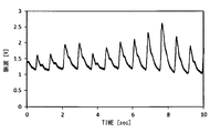
- the average value of the pulse wave amplitude was 0.65V, and the standard deviation of the pulse wave amplitude was 0.27V.
- the standard deviation of the pulse wave amplitude when the blood pressure measurement device R1 was used was significantly larger than that when the blood pressure measurement device 1 was used. From the results of this experiment, the above effect was confirmed.
- the finger insertion groove 53 is lower than the end portion 57A. Therefore, the finger to be measured 56 is in a more relaxed state when performing the caffres measurement. As a result, the S / N in the pulse wave signal is further improved.
- the blood pressure measurement device 1 further includes a pressing unit 59 that presses the finger 56 to be measured in the direction of the bottom surface 55. Therefore, the contact state between the finger to be measured 56 and the light emitting diode 31 and the photodiode 33 is further stabilized. As a result, the S / N in the pulse wave signal is further improved.
- the finger insertion groove 53 has a low inclination on the tip side of the finger 56 to be measured. Therefore, the finger to be measured 56 is in a more relaxed state when performing the caffres measurement. As a result, the S / N in the pulse wave signal is further improved.
- the shape of the upper surface 37 can be set as appropriate.
- the palm placement area 57 and the area on which the finger to be measured 56 is placed may have a continuous curved surface shape in a side section parallel to the vertical direction da.
- region 51 may be a plane in the side cross section parallel to the horizontal direction db.
- the light emitting diode 31 and the photodiode 33 may be provided on the upper surface 37.
- the photodiode 33 receives light reflected in the capillary of the finger 56 to be measured and detects a pulse wave signal.
- the light emitting diode 31 and the photodiode 33 may be provided on the pressing piece 61. Also in this case, the photodiode 33 receives light reflected in the capillary of the finger 56 to be measured and detects a pulse wave signal.
- the finger to be measured 56 may be any of an index finger, a middle finger, a ring finger, a little finger, and a thumb.
- the pulse wave sensor 5 may have another light source such as a laser light source instead of the light emitting diode 31. Further, the pulse wave sensor 5 may have other photodetectors such as a phototransistor and a CCD instead of the photodiode 33.
- the blood pressure measurement device 1 may not include the pressing unit 59.
- the thumb placement area 69 may be the same height as the end 57B.
- the blood pressure measurement device 1 may include a mounting table on which the palm 65 can be mounted separately from the housing 35.
- the shape of the mounting table can be the same as the shape of the housing 35 described above.
- the pulse wave sensor 5 is provided on the installation base, and a pulse wave signal can be acquired from the finger to be measured 56.
- the blood pressure measurement device 1 may include a sensor that detects that the finger 56 to be measured is inserted into the finger insertion groove 53.
- the blood pressure measurement device 1 may automatically start the cufflink measurement or calibration process when detecting the insertion of the finger to be measured 56 by the sensor.
- the senor examples include a mechanical sensor, a sensor that detects light, and a sensor that detects temperature.
- the mechanical sensor can detect the insertion of the finger to be measured 56 by the rotation of the pressing piece 61 when the finger to be measured 56 is inserted into the finger insertion groove 53, for example.
- the mechanical sensor may be a sensor that detects that the finger to be measured 56 presses a part or all of the pulse wave sensor 5.
- Examples of the sensor that detects light include a sensor that detects that the light incident on the photodiode 33 is changed by the insertion of the finger 56 to be measured.
- Examples of the sensor that detects the temperature include a sensor that is provided in the housing 35 and detects a temperature change when the finger 56 to be measured is inserted.
- the photodiode 33 may be provided on the bottom surface 55, and the light emitting diode 31 may be provided at a position on the end 61 ⁇ / b> A side of the pressing piece 61. .
- the photodiode 33 receives the light transmitted through the finger to be measured 56 inserted into the finger insertion groove 53 out of the light irradiated by the light emitting diode 31 and extracts it as an electrical signal.
- the light emitted from the light emitting diode 31 is near infrared light having a wavelength of 7000 mm or more.
- a system including the blood pressure measurement device as a constituent element, a program for causing a computer to function as a control unit of the blood pressure measurement device, and a non-transitive semiconductor memory or the like in which the program is recorded
- the present disclosure can also be realized in various forms such as an actual recording medium and a blood pressure measurement method.
- the blood pressure measuring device 1 described above is detected by a pulse wave sensor 5 that detects a pulse wave signal from a finger to be measured that is a part of the subject's finger, a mounting table 35 on which the palm of the subject can be placed, and a pulse wave sensor. And a blood pressure measurement unit 3 that measures blood pressure based on the pulse wave signal.
- the upper surface 37 of the mounting table includes a palm mounting area 57. This palm placement region is a region that has a convex shape upward in the vertical direction of the palm and is inclined so that the little finger side is lowered in the horizontal direction of the palm. According to such a configuration, noise in the pulse wave signal can be reduced.
Landscapes
- Health & Medical Sciences (AREA)
- Life Sciences & Earth Sciences (AREA)
- Engineering & Computer Science (AREA)
- Cardiology (AREA)
- Public Health (AREA)
- Medical Informatics (AREA)
- Veterinary Medicine (AREA)
- Physics & Mathematics (AREA)
- General Health & Medical Sciences (AREA)
- Biophysics (AREA)
- Pathology (AREA)
- Biomedical Technology (AREA)
- Heart & Thoracic Surgery (AREA)
- Animal Behavior & Ethology (AREA)
- Molecular Biology (AREA)
- Surgery (AREA)
- Physiology (AREA)
- Vascular Medicine (AREA)
- Signal Processing (AREA)
- Computer Vision & Pattern Recognition (AREA)
- Artificial Intelligence (AREA)
- Psychiatry (AREA)
- Ophthalmology & Optometry (AREA)
- Measuring Pulse, Heart Rate, Blood Pressure Or Blood Flow (AREA)
Abstract
脈波センサ(5)は、被験者の指の一部である被測定指から脈波信号を検出する。載置台(35)には、被験者の手のひらを載置可能である。血圧測定ユニット(3)は、脈波センサで検出した脈波信号に基づき血圧を測定する。載置台の上面(37)は、手のひらの縦方向において、上に凸の形状を有するとともに、手のひらの横方向において、小指側が低くなるように傾斜した手のひら載置領域(57)を備える。
Description
本出願は、2015年10月9日に出願された日本出願番号2015-201218号に基づくもので、ここにその記載内容を援用する。
本開示は、血圧測定装置に関する。
従来、脈波センサを用いて被験者の指から脈波信号を取得し、その脈波信号に基づき血圧を測定する方法が知られている(特許文献1参照)。
脈波信号を取得するとき、被験者の指に無駄な力が入っていると、脈波信号におけるノイズが大きくなってしまう。この場合、血圧を正確に測定することができない。
本開示は、脈波信号におけるノイズを低減できる血圧測定装置を提供することを目的とする。
本開示の第一の態様において、血圧測定装置は、被験者の指の一部である被測定指から脈波信号を検出する脈波センサを備える。血圧測定装置は、前記被験者の手のひらを載置可能な載置台を更に備える。血圧測定装置は、前記脈波センサで検出した前記脈波信号に基づき血圧を測定する血圧測定ユニットを更に備える。前記載置台の上面は、前記手のひらの縦方向において、上に凸の形状を有するとともに、前記手のひらの横方向において、小指側が低くなるように傾斜した手のひら載置領域を備える。
本開示についての上記目的およびその他の目的、特徴や利点は、添付の図面を参照しながら下記の詳細な記述により、より明確になる。その図面は、
血圧測定装置の構成を表すブロック図であり、
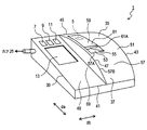
血圧測定装置の構成を表す斜視図であり、
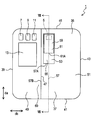
血圧測定装置の構成を表す平面図であり、
血圧測定装置の構成を表す、第1の辺の側から見た側面図であり、
血圧測定装置の構成を表す、第2の辺の側から見た側面図であり、
血圧測定装置の構成を表す、第3の辺の側から見た側面図であり、
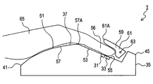
図3におけるVII-VII断面での断面図であり、
血圧測定装置の筐体上に手のひらを載置した状態を表す斜視図であり、
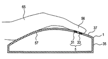
血圧測定装置の筐体上に手のひらを載置した状態を表す断面図であり、
血圧測定装置の構成を表す斜視図であり、
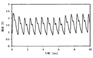
血圧測定装置を用いて取得した脈波信号を表すグラフであり、
血圧測定装置を用いて取得した脈波信号を表すグラフであり、
上面の別形態を表す側断面図であり、
血圧測定装置の別形態を表す、辺41の側から見た側面図であり、
別形態の血圧測定装置について図7と同様の断面を示す断面図であり、また
別形態の血圧測定装置における筐体上に手のひらを載置した状態を表す断面図である。
本開示の実施形態を図面に基づき説明する。
<第1実施形態>
1.血圧測定装置1の構成
血圧測定装置1の構成を図1~図9に基づき説明する。図1に示すように、血圧測定装置1は、制御部3、脈波センサ5、カフレス測定スイッチ7、カフ測定スイッチ9、校正スイッチ11、表示部13、ポンプ駆動回路15、弁駆動回路17、圧力センサ19、ポンプ21、弁23、及びカフ25を備える。
<第1実施形態>
1.血圧測定装置1の構成
血圧測定装置1の構成を図1~図9に基づき説明する。図1に示すように、血圧測定装置1は、制御部3、脈波センサ5、カフレス測定スイッチ7、カフ測定スイッチ9、校正スイッチ11、表示部13、ポンプ駆動回路15、弁駆動回路17、圧力センサ19、ポンプ21、弁23、及びカフ25を備える。
制御部3は、CPU27と、RAM、ROM、フラッシュメモリ等の半導体メモリ(以下、メモリ29とする)とを有する周知のマイクロコンピュータを中心に構成される。制御部3の各種機能は、CPU27が非遷移的実体的記録媒体に格納されたプログラムを実行することにより実現される。この例では、メモリ29が、プログラムを格納した非遷移的実体的記録媒体に該当する。また、このプログラムの実行により、プログラムに対応する方法が実行される。なお、制御部3を構成するマイクロコンピュータの数は1つでも複数でもよい。
制御部3は血圧測定ユニットに対応する。制御部3が有する機能を実現する手法はソフトウェアに限るものではなく、その一部又は全部の機能を、論理回路やアナログ回路等を組み合わせたハードウェアを用いて実現してもよい。
脈波センサ5は、被験者の指から脈波信号を取得可能な周知のセンサである。脈波センサ5が脈波信号を取得する指を以下では被測定指とする。本実施形態では被測定指は右手の人差し指である。脈波センサ5は、発光ダイオード(LED)31とフォトダイオード(PD)33とを備える。発光ダイオード31は、被測定指における皮膚に対して可視光の光を照射する。この光の波長は、5000Å~7000Åである。発光ダイオード31が照射した光の一部は皮膚の毛細血管内において反射される。フォトダイオード33は、発光ダイオード31が照射した光のうち、毛細血管内で反射された光を受光し、電気信号として取り出す。取り出した電気信号は、被験者の脈波を反映して変動する脈波信号である。
カフレス測定スイッチ7、カフ測定スイッチ9、及び校正スイッチ11は、それぞれ、ユーザが操作可能なスイッチである。カフレス測定スイッチ7が操作されたとき、血圧測定装置1は後述するカフレス測定を行う。カフ測定スイッチ9が操作されたとき、血圧測定装置1は後述するカフ測定を行う。カフ測定とは、カフ25を用いる周知の血圧測定である。校正スイッチ11が操作されたとき、血圧測定装置1は後述する校正処理を行う。表示部13は画像を表示可能なディスプレイである。
ポンプ駆動回路15、弁駆動回路17、圧力センサ19、ポンプ21、弁23、及びカフ25は、カフ測定を実行するための構成である。カフ25は、ゴム製袋を布製帯状袋内に収容した構造を有する。カフ25は、被験者の腕のうち、被測定指が属する腕とは反対側の腕に巻き回される。例えば、被測定指が右手の人差し指である場合、カフ25は被験者の左腕に巻き回される。
圧力センサ19は、カフ25内の圧力を検出する。ポンプ駆動回路15、弁駆動回路17、ポンプ21、及び弁23は、カフ25内の圧力を制御する。すなわち、ポンプ駆動回路15によりポンプ21を駆動し、弁駆動回路17により弁23を開いて空気をカフ25内に導入することで、カフ25内の圧力を増すことができる。また、弁駆動回路17により弁23の状態を切り替えて、空気をカフ25から抜くことで、カフ25内の圧力を減少させることができる。
図2~図9に示すように、血圧測定装置1は筐体35を備える。筐体35は載置台に対応する。筐体35は箱型の形状を有する。筐体35の上面37は、上方から見たとき、矩形の形状を有する。上面37の4辺を、それぞれ、辺39、41、43、45とする。以下では、上方から見て、辺39、43に平行な方向を縦方向daとする。また、上方から見て、縦方向daに直交する方向を横方向dbとする。縦方向da及び横方向dbは水平面内での方向である。
上面37は、縦方向daに平行な境界線47により、第1領域49と第2領域51とに区分される。第1領域49は、平面形状を有する。カフレス測定スイッチ7、カフ測定スイッチ9、校正スイッチ11、及び表示部13は第1領域49に設けられている。第1領域49は、辺41の側が低くなるように傾斜している。表示部13の位置は、後述する親指載置領域69とは重ならない位置である。
第2領域51は、後述する指嵌入溝53を除き、曲面形状を有する。第2領域51における曲面形状は以下のものである。すなわち、図2、図4~図9に示すように、第2領域51は、縦方向daにおいて、上に凸の形状を有する。縦方向daにおいて上に凸の形状を有するとは、縦方向daと平行な鉛直面での断面において、第2領域51が上に凸の形状を有することを意味する。上に凸の形状の例として、山型の曲面形状が挙げられる。また、図6に示すように、第2領域51は、横方向dbにおいて、境界線47の側が高く、辺43の側が低い傾斜を有する。
第2領域51は、周囲よりも一段低くなった指嵌入溝53を有する。指嵌入溝53は、被測定指載置領域に対応する。指嵌入溝53は上方から見たとき長方形の形状を有する溝である。指嵌入溝53は、第2領域51のうち、縦方向daにおいては辺45に近い位置にあり、横方向dbにおいては境界線47に近い位置にある。指嵌入溝53の長手方向は縦方向daと平行である。図7、図9に示すように、指嵌入溝53の底面55は、辺45側が低くなるように傾斜している。図8に示すように、指嵌入溝53の幅は、被測定指56を差し込むことができる幅である。
上面37のうち、指嵌入溝53よりも辺41側にある領域を手のひら載置領域57とする。底面55は、手のひら載置領域57おける指嵌入溝53側の端部57Aよりも低い。筐体35は、指嵌入溝53のうち、辺45側の位置に押圧ユニット59を備える。押圧ユニット59は、矩形板状の押圧片61を、軸63により回動可能に軸支したものである。押圧片61の長手方向は縦方向daに平行である。軸63は、押圧片61のうち、辺45側の部分を軸支する。軸63の軸方向は、横方向dbに平行である。押圧片61は、軸63を中心として、図7におけるRa-Rb方向に回動可能である。
押圧片61がRa方向に回動したとき、押圧片61のうち、軸63とは反対側の端部61Aは、底面55に近づく。また、押圧片61がRb方向に回動したとき、端部61Aは、底面55から遠ざかる。押圧片61は、Ra方向に回動するように、図示しないバネにより付勢されている。
図7、図9に示すように、発光ダイオード31、及びフォトダイオード33は、底面55に設けられている。フォトダイオード33は、発光ダイオード31が照射した光のうち、指嵌入溝53に差し込まれた被測定指56から反射された光を受光し、電気信号として取り出す。
図8、図9に示すように、被験者の手のひら65は、手のひら載置領域57上に載置される。また、被測定指56は、指嵌入溝53に差し込まれる。このとき、手のひら65の縦方向は、縦方向daと平行であり、手のひら65の横方向は、横方向dbと平行である。ここで、手のひら65の縦方向とは、被験者の手首の中心から、中指の付け根に向う方向を意味する。また、手のひら65の横方向とは、上述した手のひら65の縦方向と直交し、てのひらの面に沿った方向を意味する。
上述したように、第2領域51は、縦方向daにおいて上に凸の形状を有する。手のひら65の縦方向は、縦方向daと平行であるから、第2領域51は、手のひら65の縦方向において上に凸の形状を有する。第2領域51の一部である手のひら載置領域57も、手のひら65の縦方向において上に凸の形状を有する。
また、上述したように、第2領域51は、横方向dbにおいて、境界線47の側が高く、辺43の側が低くなる傾斜を有する。手のひら65の横方向は、横方向dbと平行である。また、辺43の側は、手のひら65における小指の方向に該当する。よって、第2領域51は、小指側が低くなる傾斜を有する。第2領域51の一部である手のひら載置領域57も、小指側が低くなる傾斜を有する。
押圧片61は、指嵌入溝53に差し込まれた被測定指56の先端部を底面55の方向に押圧する。発光ダイオード31及びフォトダイオード33は、被測定指56における先端部を上下から挟む位置にある。
図8に示すように、被験者の親指67は、第1領域49のうち、境界線47に近い領域(以下では親指載置領域69とする)上に載置される。親指載置領域69は、手のひら載置領域57における親指67側の端部57Bよりも低い。
2.血圧測定装置1が実行する処理
(1)カフレス測定
カフレス測定スイッチ7が操作されたとき、血圧測定装置1はカフレス測定を行う。カフレス測定のとき、制御部3は、まず、脈波センサ5を用いて所定期間継続して脈波信号を取得する。次に、制御部3は、取得した脈波信号に基づき被験者の血圧を測定する。脈波信号に基づき血圧を測定する方法は、周知の方法(例えば、実開平7-9305号公報、特開平7-308295号公報等に開示された方法)の中から適宜選択することができる。
(1)カフレス測定
カフレス測定スイッチ7が操作されたとき、血圧測定装置1はカフレス測定を行う。カフレス測定のとき、制御部3は、まず、脈波センサ5を用いて所定期間継続して脈波信号を取得する。次に、制御部3は、取得した脈波信号に基づき被験者の血圧を測定する。脈波信号に基づき血圧を測定する方法は、周知の方法(例えば、実開平7-9305号公報、特開平7-308295号公報等に開示された方法)の中から適宜選択することができる。
次に、制御部3は、血圧の校正を行う。血圧の校正とは、上記のように測定した血圧に、校正値を加える処理である。校正値とは、同一の被験者について同時に、カフ測定とカフレス測定とを行い、前者の測定値から後者の測定値を差し引いた値である。校正値は、後述する校正処理により決定され、メモリ29に記憶されている。血圧測定装置1は、校正後の測定値を表示部13に表示する。
(2)カフ測定
カフ測定スイッチ9が操作されたとき、血圧測定装置1は、以下のようにカフ測定を行う。制御部3は、まず、ポンプ駆動回路15、弁駆動回路17、ポンプ21、及び弁23を用いて、カフ25内の圧力を180mmHg程度の目標圧迫圧とする。次に、制御部3は、ポンプ駆動回路15、弁駆動回路17、ポンプ21、及び弁23を用いて、カフ25内の圧力を、3mmHg/sec程度の緩やかな速度で下降させる。制御部3は、圧力を下降させている過程で圧力センサ19により得られる信号における振幅の変化に基づき、オシロメトリックス方式の血圧値決定プログラムに従って、最高血圧値、平均血圧値、及び最低血圧値を測定する。血圧測定装置1は、カフ測定の測定値を表示部13に表示する。
カフ測定スイッチ9が操作されたとき、血圧測定装置1は、以下のようにカフ測定を行う。制御部3は、まず、ポンプ駆動回路15、弁駆動回路17、ポンプ21、及び弁23を用いて、カフ25内の圧力を180mmHg程度の目標圧迫圧とする。次に、制御部3は、ポンプ駆動回路15、弁駆動回路17、ポンプ21、及び弁23を用いて、カフ25内の圧力を、3mmHg/sec程度の緩やかな速度で下降させる。制御部3は、圧力を下降させている過程で圧力センサ19により得られる信号における振幅の変化に基づき、オシロメトリックス方式の血圧値決定プログラムに従って、最高血圧値、平均血圧値、及び最低血圧値を測定する。血圧測定装置1は、カフ測定の測定値を表示部13に表示する。
(3)校正処理
校正スイッチ11が操作されたとき、血圧測定装置1は校正処理を行う。校正処理とは、カフ測定とカフレス測定とを同時に行い、前者の測定値から後者の測定値を差し引いた値を校正値としてメモリ29に記憶する処理である。校正処理後、制御部3は、カフ測定の測定値を表示部13に表示する。
校正スイッチ11が操作されたとき、血圧測定装置1は校正処理を行う。校正処理とは、カフ測定とカフレス測定とを同時に行い、前者の測定値から後者の測定値を差し引いた値を校正値としてメモリ29に記憶する処理である。校正処理後、制御部3は、カフ測定の測定値を表示部13に表示する。
3.血圧測定装置1が奏する効果
(1A)手のひら載置領域57の形状は、手のひら65の縦方向において、上に凸の形状を有するとともに、手のひら65の横方向において、小指側が低くなるように傾斜した形状である。そのため、カフレス測定を行うとき、被測定指56に無駄な力が入り難く、被測定指56はリラックスした状態となる。その結果、脈波信号におけるノイズが少なくなり、脈波信号のS/Nが向上する。
(1A)手のひら載置領域57の形状は、手のひら65の縦方向において、上に凸の形状を有するとともに、手のひら65の横方向において、小指側が低くなるように傾斜した形状である。そのため、カフレス測定を行うとき、被測定指56に無駄な力が入り難く、被測定指56はリラックスした状態となる。その結果、脈波信号におけるノイズが少なくなり、脈波信号のS/Nが向上する。
上記の効果を確かめるために実験を行った。血圧測定装置1を用いて、脈波信号を取得した。その結果を図11に示す。脈波振幅の平均値は1.37Vであり、脈波振幅の標準偏差は0.12Vであった。
一方、比較例として、図10に示すように、基本的な構成は血圧測定装置1と同様であるが、筐体135の上面137が全て平面である血圧測定装置R1を用意した。上面137の表面には、脈波センサが備える発光ダイオード31及びフォトダイオード33と、表示部13とが設けられている。
手のひら65を上面137に載置し、血圧測定装置R1を用いて脈波信号を取得した。その結果を図12に示す。脈波振幅の平均値は0.65Vであり、脈波振幅の標準偏差は0.27Vであった。血圧測定装置R1を使用した場合における脈波振幅の標準偏差は、血圧測定装置1を使用した場合に比べて顕著に大きかった。この実験結果から、上記の効果が裏付けられた。
(1B)指嵌入溝53は、端部57Aよりも低い。そのため、カフレス測定を行うとき、被測定指56は一層リラックスした状態となる。その結果、脈波信号におけるS/Nが一層向上する。
(1C)血圧測定装置1は、被測定指56を底面55の方向に押圧する押圧ユニット59をさらに備える。そのため、被測定指56と、発光ダイオード31及びフォトダイオード33との接触状態が一層安定する。その結果、脈波信号におけるS/Nが一層向上する。
(1D)指嵌入溝53は、被測定指56の先端側が低い傾斜を有する。そのため、カフレス測定を行うとき、被測定指56は一層リラックスした状態となる。その結果、脈波信号におけるS/Nが一層向上する。
(1E)親指載置領域69は、端部57Bよりも低い。そのため、カフレス測定を行うとき、被測定指56は一層リラックスした状態となる。その結果、脈波信号におけるS/Nが一層向上する。
<その他の実施形態>
以上、本開示を実施するための形態について説明したが、本開示は上述の実施形態に限定されることなく、種々変形して実施することができる。
<その他の実施形態>
以上、本開示を実施するための形態について説明したが、本開示は上述の実施形態に限定されることなく、種々変形して実施することができる。
(1)上面37の形状は適宜設定することができる。例えば、図13に示すように、縦方向daに平行な側断面において、手のひら載置領域57と、被測定指56を載置する領域とが、連続する曲面形状を有していてもよい。また、図14に示すように、横方向dbに平行な側断面において、第2領域51は平面であってもよい。
(2)図13に示すように、発光ダイオード31及びフォトダイオード33を上面37に設けてもよい。この場合、フォトダイオード33は、被測定指56の毛細血管内において反射された光を受光し、脈波信号を検出する。また、発光ダイオード31及びフォトダイオード33を押圧片61に設けてもよい。この場合も、フォトダイオード33は、被測定指56の毛細血管内において反射された光を受光し、脈波信号を検出する。
(3)被測定指56は、人差し指、中指、薬指、小指、及び親指のうちのいずれであってもよい。
(4)脈波センサ5は、発光ダイオード31に代えて、レーザ光源等の他の光源を有していてもよい。また、脈波センサ5は、フォトダイオード33に代えて、フォトトランジスタ、CCD等の他の光検出器を有していてもよい。
(5)血圧測定装置1は、押圧ユニット59を備えなくてもよい。
(6)親指載置領域69は、端部57Bと同じ高さであってもよい。
(7)血圧測定装置1は、筐体35とは別に、手のひら65を載置可能な載置台を備えていてもよい。その載置台の形状は、上述した筐体35の形状と同様とすることができる。また、その設置台に脈波センサ5を備え、被測定指56から脈波信号を取得することができる。
(8)血圧測定装置1は、指嵌入溝53に被測定指56が挿入されたことを検出するセンサを備えていてもよい。血圧測定装置1は、そのセンサにより被測定指56の挿入を検出したとき、カフレス測定又は校正処理を自動的に開始してもよい。
上記のセンサとしては、例えば、機械式のセンサ、光を検出するセンサ、温度を検出するセンサ等が挙げられる。機械式のセンサは、例えば、指嵌入溝53に被測定指56が挿入されたときの押圧片61の回動により、被測定指56の挿入を検出することができる。
また、機械式のセンサは、脈波センサ5の一部又は全部を被測定指56が押圧することを検出するセンサであってもよい。光を検出するセンサとしては、例えば、フォトダイオード33に入射する光が、被測定指56の挿入により変化することを検出するセンサが挙げられる。温度を検出するセンサとしては、例えば、筐体35内に設けられ、被測定指56が挿入されたときの温度変化を検出するセンサが挙げられる。
(9)前記第1実施形態において、図15、図16に示すように、フォトダイオード33を底面55に設け、発光ダイオード31を押圧片61のうち、端部61A側の位置に設けてもよい。フォトダイオード33は、発光ダイオード31が照射した光のうち、指嵌入溝53に差し込まれた被測定指56を透過した光を受光し、電気信号として取り出す。この場合、発光ダイオード31が照射する光は、波長が7000Å以上の近赤外光である。
(10)上記実施形態における1つの構成要素が有する機能を複数の構成要素として分散させたり、複数の構成要素が有する機能を1つの構成要素に統合させたりしてもよい。また、上記実施形態の構成の一部を省略してもよい。また、上記実施形態の構成の少なくとも一部を、他の上記実施形態の構成に対して付加又は置換してもよい。なお、特許請求の範囲に記載した文言のみによって特定される技術思想に含まれるあらゆる態様が本開示の実施形態である。
(11)上述した血圧測定装置の他、当該血圧測定装置を構成要素とするシステム、当該血圧測定装置の制御部としてコンピュータを機能させるためのプログラム、このプログラムを記録した半導体メモリ等の非遷移的実態的記録媒体、血圧測定方法等、種々の形態で本開示を実現することもできる。
上述の血圧測定装置1は、被験者の指の一部である被測定指から脈波信号を検出する脈波センサ5と、被験者の手のひらを載置可能な載置台35と、脈波センサで検出した脈波信号に基づき血圧を測定する血圧測定ユニット3とを備える。載置台の上面37は、手のひら載置領域57を備える。この手のひら載置領域は、手のひらの縦方向において、上に凸の形状を有するとともに、手のひらの横方向において、小指側が低くなるように傾斜した領域である。このような構成によれば、脈波信号におけるノイズを低減できる。
本開示は、実施例に準拠して記述されたが、本開示は当該実施例や構造に限定されるものではないと理解される。本開示は、様々な変形例や均等範囲内の変形をも包含する。加えて、様々な組み合わせや形態、さらには、それらに一要素のみ、それ以上、あるいはそれ以下、を含む他の組み合わせや形態をも、本開示の範疇や思想範囲に入るものである。
Claims (5)
- 血圧測定装置(1)であって、
被験者の指の一部である被測定指から脈波信号を検出する脈波センサ(5)と、
前記被験者の手のひらを載置可能な載置台(35)と、
前記脈波センサで検出した前記脈波信号に基づき血圧を測定する血圧測定ユニット(3)と、
を備え、
前記載置台の上面(37)は、前記手のひらの縦方向において、上に凸の形状を有するとともに、前記手のひらの横方向において、小指側が低くなるように傾斜した手のひら載置領域(57)を備える血圧測定装置。 - 請求項1に記載の血圧測定装置であって、
前記上面は、前記手のひら載置領域における前記被測定指側の端部よりも低く、前記被測定指を載置可能な被測定指載置領域(53)をさらに備える血圧測定装置。 - 請求項2に記載の血圧測定装置であって、
前記被測定指を前記被測定指載置領域の方向に押圧する押圧ユニット(59)をさらに備える血圧測定装置。 - 請求項2又は3に記載の血圧測定装置であって、
前記被測定指載置領域は、前記被測定指の先端側が低い傾斜を有するように構成された血圧測定装置。 - 請求項1~4のいずれか1項に記載の血圧測定装置であって、
前記上面は、前記手のひら載置領域における親指側の端部よりも低く、前記被験者の親指を載置可能な親指載置領域(69)をさらに備える血圧測定装置。
Priority Applications (2)
| Application Number | Priority Date | Filing Date | Title |
|---|---|---|---|
| US15/744,498 US20180199831A1 (en) | 2015-10-09 | 2016-09-05 | Blood pressure measurement device |
| CN201680038004.6A CN107708536A (zh) | 2015-10-09 | 2016-09-05 | 血压测定装置 |
Applications Claiming Priority (2)
| Application Number | Priority Date | Filing Date | Title |
|---|---|---|---|
| JP2015201218A JP2017070630A (ja) | 2015-10-09 | 2015-10-09 | 血圧測定装置 |
| JP2015-201218 | 2015-10-09 |
Publications (1)
| Publication Number | Publication Date |
|---|---|
| WO2017061204A1 true WO2017061204A1 (ja) | 2017-04-13 |
Family
ID=58487447
Family Applications (1)
| Application Number | Title | Priority Date | Filing Date |
|---|---|---|---|
| PCT/JP2016/075934 Ceased WO2017061204A1 (ja) | 2015-10-09 | 2016-09-05 | 血圧測定装置 |
Country Status (4)
| Country | Link |
|---|---|
| US (1) | US20180199831A1 (ja) |
| JP (1) | JP2017070630A (ja) |
| CN (1) | CN107708536A (ja) |
| WO (1) | WO2017061204A1 (ja) |
Families Citing this family (3)
| Publication number | Priority date | Publication date | Assignee | Title |
|---|---|---|---|---|
| JP7101509B2 (ja) * | 2018-03-27 | 2022-07-15 | キヤノン株式会社 | 生体情報測定装置 |
| CN109350033A (zh) * | 2018-11-26 | 2019-02-19 | 安徽昱康智能科技有限公司 | 一种弧形采集电极 |
| KR102926338B1 (ko) | 2020-05-22 | 2026-02-10 | 삼성전자주식회사 | 웨어러블 기기 및 생체정보 추정 방법 |
Citations (6)
| Publication number | Priority date | Publication date | Assignee | Title |
|---|---|---|---|---|
| WO1999000053A1 (en) * | 1997-06-27 | 1999-01-07 | Toa Medical Electronics Co., Ltd. | Living body inspecting apparatus and noninvasive blood analyzer using the same |
| JP2003159250A (ja) * | 2001-07-09 | 2003-06-03 | Seiko Instruments Inc | 血液レオロジー測定装置 |
| JP2009506844A (ja) * | 2005-08-31 | 2009-02-19 | カルヘルス インコーポレイテッド | 一般の装置と共に用いるための血圧計 |
| JP2013059372A (ja) * | 2011-09-12 | 2013-04-04 | Panasonic Corp | パソコン操作用のマウス |
| JP2015043882A (ja) * | 2013-08-28 | 2015-03-12 | 株式会社デンソー | 血圧計 |
| WO2015151132A1 (ja) * | 2014-04-01 | 2015-10-08 | Cyberdyne株式会社 | 血圧測定装置 |
Family Cites Families (15)
| Publication number | Priority date | Publication date | Assignee | Title |
|---|---|---|---|---|
| US5218966A (en) * | 1987-06-12 | 1993-06-15 | Omron Tateisi Electronics Co. | Electronic blood pressure meter |
| US5209230A (en) * | 1990-10-19 | 1993-05-11 | Nellcor Incorporated | Adhesive pulse oximeter sensor with reusable portion |
| US5553613A (en) * | 1994-08-17 | 1996-09-10 | Pfizer Inc. | Non invasive blood analyte sensor |
| JP3603046B2 (ja) * | 2001-06-13 | 2004-12-15 | コーリンメディカルテクノロジー株式会社 | 透析用血圧監視装置および透析装置 |
| JP4306381B2 (ja) * | 2003-09-17 | 2009-07-29 | オムロンヘルスケア株式会社 | 脈波測定装置用手首固定具および脈波測定装置 |
| US7179228B2 (en) * | 2004-04-07 | 2007-02-20 | Triage Wireless, Inc. | Cuffless system for measuring blood pressure |
| US11607152B2 (en) * | 2007-06-12 | 2023-03-21 | Sotera Wireless, Inc. | Optical sensors for use in vital sign monitoring |
| US20100004518A1 (en) * | 2008-07-03 | 2010-01-07 | Masimo Laboratories, Inc. | Heat sink for noninvasive medical sensor |
| US20140073969A1 (en) * | 2012-09-12 | 2014-03-13 | Neurosky, Inc. | Mobile cardiac health monitoring |
| CN103431848B (zh) * | 2013-09-22 | 2015-10-21 | 天津普仁万合信息技术有限公司 | 一种便携式无源传感器 |
| WO2016017579A1 (ja) * | 2014-07-28 | 2016-02-04 | シナノケンシ株式会社 | 生体情報読取装置 |
| WO2016033121A1 (en) * | 2014-08-25 | 2016-03-03 | Georgia Tech Research Corporation | Noninvasive systems and methods for monitoring health characteristics |
| US10213123B2 (en) * | 2014-09-19 | 2019-02-26 | Mocacare, Corp. | Cardiovascular monitoring device |
| US10383518B2 (en) * | 2015-03-31 | 2019-08-20 | Midmark Corporation | Electronic ecosystem for medical examination room |
| WO2018066342A1 (ja) * | 2016-10-07 | 2018-04-12 | 株式会社村田製作所 | 把持型脈波測定装置 |
-
2015
- 2015-10-09 JP JP2015201218A patent/JP2017070630A/ja active Pending
-
2016
- 2016-09-05 WO PCT/JP2016/075934 patent/WO2017061204A1/ja not_active Ceased
- 2016-09-05 US US15/744,498 patent/US20180199831A1/en not_active Abandoned
- 2016-09-05 CN CN201680038004.6A patent/CN107708536A/zh active Pending
Patent Citations (6)
| Publication number | Priority date | Publication date | Assignee | Title |
|---|---|---|---|---|
| WO1999000053A1 (en) * | 1997-06-27 | 1999-01-07 | Toa Medical Electronics Co., Ltd. | Living body inspecting apparatus and noninvasive blood analyzer using the same |
| JP2003159250A (ja) * | 2001-07-09 | 2003-06-03 | Seiko Instruments Inc | 血液レオロジー測定装置 |
| JP2009506844A (ja) * | 2005-08-31 | 2009-02-19 | カルヘルス インコーポレイテッド | 一般の装置と共に用いるための血圧計 |
| JP2013059372A (ja) * | 2011-09-12 | 2013-04-04 | Panasonic Corp | パソコン操作用のマウス |
| JP2015043882A (ja) * | 2013-08-28 | 2015-03-12 | 株式会社デンソー | 血圧計 |
| WO2015151132A1 (ja) * | 2014-04-01 | 2015-10-08 | Cyberdyne株式会社 | 血圧測定装置 |
Also Published As
| Publication number | Publication date |
|---|---|
| CN107708536A (zh) | 2018-02-16 |
| US20180199831A1 (en) | 2018-07-19 |
| JP2017070630A (ja) | 2017-04-13 |
Similar Documents
| Publication | Publication Date | Title |
|---|---|---|
| JP5565463B2 (ja) | 脈波センサ装置 | |
| JP5900632B2 (ja) | 生体センサ、及び、生体センサの製造方法 | |
| US20130310659A1 (en) | Blood pressure measuring device | |
| US20160198962A1 (en) | Apparatus and method for simultaneously detecting surface pressure and blood volume | |
| JP6293927B2 (ja) | センサ | |
| US9716835B2 (en) | Biological information acquiring device | |
| EP3015062A1 (en) | Optical sensor arrangement for an optical measurement of biological parameters and watch comprising the optical sensor arrangement | |
| JPWO2017208645A1 (ja) | 流量測定装置、流量測定方法、圧力測定装置、及び圧力測定方法 | |
| CN104939812A (zh) | 生物体信息检测装置以及电子设备 | |
| WO2017061204A1 (ja) | 血圧測定装置 | |
| CN104939811A (zh) | 生物体信息检测装置以及电子设备 | |
| CN107106036A (zh) | 在测量生理参数中用于光学隔离的系统和方法 | |
| KR20210144356A (ko) | 웨어러블 기기 및 생체정보 추정 방법 | |
| JP2017153616A (ja) | パルスオキシメータプローブ | |
| WO2018047788A1 (ja) | 血圧測定装置、血圧測定装置の制御方法およびプログラム | |
| CN113164090A (zh) | 包括模制光束成形元件的集成光学生物传感器 | |
| US9772224B2 (en) | Information acquisition apparatus and information acquisition method | |
| US20150238131A1 (en) | Apparatus having a light emitting part | |
| EP3871588B1 (en) | Electronic device and method for estimating bio-information | |
| KR20220053450A (ko) | 생체정보 추정 장치, 다중신호 측정센서 | |
| JP2019063308A (ja) | 生体関連情報計測装置 | |
| WO2025077505A1 (zh) | 一种检测装置、电子设备及其控制方法 | |
| WO2015182129A1 (ja) | 測定装置 | |
| JP2017000314A (ja) | 脈波計 | |
| TWI619471B (zh) | 測定裝置及測定方法 |
Legal Events
| Date | Code | Title | Description |
|---|---|---|---|
| 121 | Ep: the epo has been informed by wipo that ep was designated in this application |
Ref document number: 16853358 Country of ref document: EP Kind code of ref document: A1 |
|
| WWE | Wipo information: entry into national phase |
Ref document number: 15744498 Country of ref document: US |
|
| NENP | Non-entry into the national phase |
Ref country code: DE |
|
| 122 | Ep: pct application non-entry in european phase |
Ref document number: 16853358 Country of ref document: EP Kind code of ref document: A1 |