WO2017057728A1 - ブロー成形方法 - Google Patents
ブロー成形方法 Download PDFInfo
- Publication number
- WO2017057728A1 WO2017057728A1 PCT/JP2016/079116 JP2016079116W WO2017057728A1 WO 2017057728 A1 WO2017057728 A1 WO 2017057728A1 JP 2016079116 W JP2016079116 W JP 2016079116W WO 2017057728 A1 WO2017057728 A1 WO 2017057728A1
- Authority
- WO
- WIPO (PCT)
- Prior art keywords
- molded body
- preform
- blow
- molded
- blow molding
- Prior art date
- Legal status (The legal status is an assumption and is not a legal conclusion. Google has not performed a legal analysis and makes no representation as to the accuracy of the status listed.)
- Ceased
Links
Images









Classifications
-
- B—PERFORMING OPERATIONS; TRANSPORTING
- B29—WORKING OF PLASTICS; WORKING OF SUBSTANCES IN A PLASTIC STATE IN GENERAL
- B29C—SHAPING OR JOINING OF PLASTICS; SHAPING OF MATERIAL IN A PLASTIC STATE, NOT OTHERWISE PROVIDED FOR; AFTER-TREATMENT OF THE SHAPED PRODUCTS, e.g. REPAIRING
- B29C49/00—Blow-moulding, i.e. blowing a preform or parison to a desired shape within a mould; Apparatus therefor
- B29C49/02—Combined blow-moulding and manufacture of the preform or the parison
- B29C49/04—Extrusion blow-moulding
- B29C49/0411—Means for defining the wall or layer thickness
- B29C49/04114—Means for defining the wall or layer thickness for keeping constant thickness
-
- B—PERFORMING OPERATIONS; TRANSPORTING
- B29—WORKING OF PLASTICS; WORKING OF SUBSTANCES IN A PLASTIC STATE IN GENERAL
- B29C—SHAPING OR JOINING OF PLASTICS; SHAPING OF MATERIAL IN A PLASTIC STATE, NOT OTHERWISE PROVIDED FOR; AFTER-TREATMENT OF THE SHAPED PRODUCTS, e.g. REPAIRING
- B29C49/00—Blow-moulding, i.e. blowing a preform or parison to a desired shape within a mould; Apparatus therefor
- B29C49/22—Blow-moulding, i.e. blowing a preform or parison to a desired shape within a mould; Apparatus therefor using multilayered preforms or parisons
Definitions
- the present invention relates to a blow molding method for performing blow molding by blowing air into a parison sandwiched between molds, and particularly relates to an improvement for making the thickness of a molded body to be molded uniform.
- the present invention also relates to a blow molding method for performing biaxial stretch blow by combining a preform and a tubular molded body.
- a blow molding method As a method for molding a plastic container (bottle), a blow molding method is widely used. An injection molded preform is set in a mold, and air is blown to form a mold cavity 2 An axial stretch blow molding method or the like is known.
- a material to be used has a gas barrier property, or a colorant or an ultraviolet absorber is added to a plastic material.
- a multilayer preform may be injection-molded and blow-molded, and various molding methods for multilayer preforms have been proposed.
- cost for example, because advanced technology is required for molding a multilayer preform, and a large amount of equipment investment is required for the molding apparatus.
- an outer shrink member is provided on the outer side of the preform, a composite preform having a preform and an outer shrink member in close contact with the outer side of the preform is manufactured, and the composite preform is formed in a blow mold.
- a blow molding method is disclosed in which a preform of a composite preform and an outer contracting member are expanded together by performing blow molding on the reform.
- Patent Document 2 discloses a blow molding method in which an inner label member is provided on the outer side of a preform and the preform and the inner label member are expanded integrally as in Patent Document 1. Thereby, it is possible to realize a blow molding method capable of eliminating the step of applying a label by a labeler.
- blow molding has a problem that it is difficult to make the thickness uniform. In blow molding, it is necessary to pinch off both ends of the parison to blow in air, but the parison tends to flatten during this pinch-off, resulting in uneven thickness in the circumferential direction. Tend to be.
- the non-uniform thickness of the tubular molded body leads to a decrease in quality, which is not preferable.
- the method of molding a composite container by mounting a tube-shaped molded body on the outside of the preform and blow-molding does not give functionality to the entire container, and demands for diversification of plastic containers The fact is that it is not always possible to cope with.
- the present invention has been proposed in view of such a conventional situation, and blow molding that can suppress uneven thickness in blow molding and can form a product having a uniform thickness in the circumferential direction. It aims to provide a method.
- an object of the present invention is to provide a blow molding method capable of imparting functionality to the entire container, for example, capable of easily producing a delamination container.
- the blow molding method of the present invention is a blow molding method in which a parison extruded from an extruder is sandwiched between a pair of molds and blow molded.
- the plurality of products are blow-molded in a lump by pinching off only the end portions on the unconnected side of the products at both ends.
- the parison In blow molding, the parison is flattened in the vicinity of the pinch-off part, leading to non-uniform thickness. If the both ends of one product are pinched off, a region having a non-uniform thickness will spread.
- the blow molding method of the present invention since a plurality of products are collectively formed in a connected form, so-called a plurality of products are formed. Therefore, the number of pinch-off portions in each product is reduced, and the thickness becomes uneven due to pinch-off. Minimized.
- the blow molding method of the present invention is a biaxial method in which a pre-blow-molded tube-shaped molded body is loaded on the inside of a preform that has been injection-molded, and the tube-shaped molded body is stacked on the inside of the preform. It is characterized by performing stretch blow molding.
- the inner surface of the preform has a smooth surface without any irregularities corresponding to the screw portion and various flange portions. Therefore, the tubular molded body can be loaded in close contact with the preform even at the mouth portion of the preform. If a tube-shaped molded body that reaches the opening end of the preform is loaded and biaxial stretch blow molding is performed, the entire inner surface of the container is molded with the tubular molded body, and functionality is imparted to the entire container. Is done.
- blow molding method of the present invention non-uniform thickness can be suppressed, and a product having a uniform thickness in the circumferential direction can be molded. Therefore, for example, when a tubular molded body is mounted on the outside of a preform and blown to produce a composite container, by applying the blow molding method of the present invention to blow molding of the tubular molded body, It is possible to produce high quality composite containers.
- the entire container can have a double structure, and various functions can be imparted to the entire container. Furthermore, a so-called delamination container can be easily produced as a double-structure container.
- FIG. 3B is a transverse sectional view taken along line XX in FIG. 3A. It is a longitudinal cross-sectional view which shows typically the form of the parison in two-piece blow molding.
- FIG. 3B is a cross-sectional view taken along line YY in FIG.
- FIG. 1 It is a figure which shows an example of the method of latching the opening edge part of a tubular molded object to the opening edge part of a preform, (a) shows the bending process by a jig
- the blow molding method of the present invention is a blow molding method in which a parison extruded from an extruder is sandwiched between a pair of molds and blow molded.
- the plurality of products are blow-molded together by pinching off only the end portion on the side that is not.
- blow molding is performed by combining a plurality of products so as to be connected in series in a so-called multiple-piece state.
- the number of products formed at one time may be two or three, and may be four or more. However, the larger the number of products formed at one time, the larger the size of the mold becomes necessary. .
- the shape of each product is limited to that having both ends open. Accordingly, the number of molded bodies to be molded at a time may be appropriately set according to the required product shape, facility scale, and the like.
- FIG. 1 shows a form of a molded body 1 molded in the present embodiment.
- the molded body 1 molded in the present embodiment has a form in which two tubular molded bodies (products) 2 and 3 are connected in series.
- Each of the tubular molded bodies 2 and 3 is molded by being integrally connected to each other via the connecting portion 4 while being closed with pinch-off portions 2A and 3A at one end side and opened at the other end side. Yes.
- the connecting portion 4 that connects the tubular molded bodies 2 and 3 that are products is formed with a diameter slightly smaller than the diameter of the body portion of each tubular molded body 2 and 3.
- the diameter of the connecting portion 4 is set to be smaller than the diameter of the body portion of the tubular molded bodies 2 and 3 by setting the blowing needle at this position, and at the time of blow molding, the diameter of the blowing needle to the parison is set. This is for smooth insertion.
- FIG. 2A a cylindrical parison 11 is extruded from a die of an extruder 12, and is sandwiched between a pair of split molds 13 and 14 as shown in FIG. 2B.
- the parison 11 is formed by extruding the melt-kneaded raw resin from the die of the extruder 12, and any thermoplastic resin can be used as the raw resin.
- any thermoplastic resin can be used as the raw resin.
- polyolefin resins such as polyethylene and polypropylene
- polyester resins such as polyethylene terephthalate
- polyamide resins such as nylon under the trade name
- ethylene-vinyl alcohol resin excellent in gas barrier properties etc.
- additives such as colorants, light-shielding agents, ultraviolet absorbers, lubricants, fillers, and the like can be added to the raw material resin.
- the material to be added may be appropriately selected according to the performance, function, and the like.
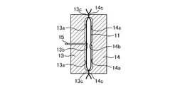
- Each of the split molds 13 and 14 has two cavities 13a and 14a corresponding to the shape of the tubular molded bodies 2 and 3 as products, and the cavity corresponding to the shape of the tubular molded bodies 2 and 3 is provided.
- Projections 13b and 14b are formed between 13a and 14a to form a slightly small-diameter connecting portion 4.
- pinch-off portions 13c and 14c are provided at the ends of the cavities 13a and 14a opposite to the side connected by the connecting portion 4.
- the blowing needle 15 is inserted into the parison 11 at the protruding portion 13b corresponding to the connecting portion 4, and the air blow I do.
- the distance between the parison 11 and the split mold 13 is greater than the distance between the parison 11 and the split mold 13 in the cavities 13a and 14a according to the shape of the tubular molded bodies 2 and 3.
- the blowing needle 15 can be easily inserted into the parison 11.
- the connecting part 4 By making the connecting part 4 smaller in diameter than the diameter of the body part of the tubular molded bodies 2 and 3, the mold part corresponding to the connecting part 4 is projected beyond the mold part corresponding to the body part. As a result, the mold part corresponding to the connecting portion 4 and the parison 11 come close to each other.
- the inner diameter of the mold portion corresponding to the connecting portion 4 is preferably substantially equal to the outer diameter of the extruded parison. Specifically, the inner diameter of the mold portion is 0 to 2 mm from the outer diameter of the parison. It is preferable. In order to surely prevent the parison from being caught in the mold part, the inner diameter of the part is preferably larger than the outer diameter of the parison by 0.5 mm or more.
- the blowing needle 15 is installed in the protruding portion 13b which is a mold portion protruding corresponding to the connecting portion 4, and the blowing needle 15 is inserted into the parison 11 and air blown.
- the blowing needle 15 is installed on the protruding portion 13 b and a vacuum suction hole is provided around the blowing needle 15.
- vacuum suction is performed through these vacuum suction holes.
- the parison 11 is attracted to the mold (projecting portion 13b). Since the distance between the protruding portion 13b and the parison 11 is short, the parison 11 is quickly attracted to and closely contacts the protruding portion 13b. Therefore, the spray needle 15 can be smoothly inserted into the parison 11.
- a concave portion is locally provided in the protruding portion 13b.
- a needle hole may be provided, and a plurality of suction holes for sucking the parison may be arranged around the needle hole in the recess so as to surround the needle hole.
- the protrusion 13b is provided with a circular recess having a diameter of about 4 to 6 mm and a depth of about 2 to 4 mm, a needle hole with a diameter of 2 to 3 mm is provided at the center of the recess, and a 45 ° angle with respect to the needle hole is 45 °.
- Eight suction holes may be arranged around the needle hole at intervals.
- the periphery of the concave portion is close to the parison, when the parison is sucked by the suction hole in the concave portion, the parison partially enters the concave portion, and the parison can be firmly held in the portion where the parison has entered. Thereby, the blowing needle can be more reliably inserted into the parison.
- the parison 11 is pressed against the inner walls of the cavities 13a and 14a of the split molds 13 and 14 by the air blow by the blowing needle 15, and is formed into the cavities 13a and 14a.
- the mold is opened and the molded body is taken out.
- the molded body to be molded is as shown in FIG.
- the taken-out molded object 1 is cut
- 3A and 3B show the form of the parison 11 in blow molding in which the product is a so-called single piece.
- the cavities 21a and 22a have one cavity 21a and 22a corresponding to one product, and pinch-off portions 21b and 22b are provided at both ends thereof. .
- pinch-off portions 21b and 22b are provided on both sides of the product (that is, cavities 21a and 22a), and the distance L1 between the pinch-off portions 21b and 22b is small.
- the pinch-off portions 21b and 22b a large force is applied to the parison 11 at the time of biting, which causes the deformation of the parison 11. If the distance L1 is small, the influence affects the entire product.
- FIG. 3B shows a cross section of the parison 11 when sandwiched between the divided molds 21 and 22, and the parison 11 is flattened by the influence of the pinch-off portions 21b and 22b provided on both sides of the cavities 21a and 22a. The phenomenon of being crushed is seen. If the parison 11 is flattened, the parison 11 is not uniformly stretched when air blown, and the variation in thickness particularly in the circumferential direction increases.
- the distance L2 between the pinch-off portions 13c and 14c at both ends is approximately twice as large as that in the case of the previous single piece, and the influence of the biting at the pinch-off portions 13c and 14c is greatly reduced.
- the cross-sectional shape of the parison 11 sandwiched between the split molds 13 and 14 becomes nearly circular. If the parison 11 is circular, it is uniformly stretched in all directions during the air blow and is formed with a uniform thickness.
- the products (tube-shaped molded bodies 2 and 3) molded by the blow molding method of the present embodiment having such a mold design are excellent in thickness uniformity in the circumferential direction. It is possible to produce high quality composite containers.
- a preform 40 made of a plastic material is prepared.
- the molding method of the preform 40 include injection molding using an injection molding machine and extrusion molding.
- thermoplastic resin As the constituent material of the preform 40, any thermoplastic resin may be mentioned, and it may be appropriately selected according to the use and performance of the composite container.
- thermoplastic resin include PE (polyethylene), PP (polypropylene), PET (polyethylene terephthalate), PEN (polyethylene naphthalate), and the like.
- the preform 40 can have a multilayer structure.
- a two-layer preform a product name nylon MXD6, a product name nylon MXD6 + fatty acid salt, PGA (polyglycolic acid), EVOH (ethylene vinyl alcohol copolymer) or PEN (polyethylene naphthalate), etc. It is also possible to form a preform composed of three or more layers having a resin having a property as an intermediate layer.
- the tubular molded body 2 (3) is mounted on the outside of the preform 40 as a tubular molded body.
- the tubular molded bodies 2 and 3 have a bottomed cylindrical shape as a whole, and have a cylindrical body portion and a bottom portion closed by pinch-off.
- the tubular molded body 2 (3) is mounted so as to cover the entire preform 40 except for the neck portion of the preform 40.
- the preheating temperature may be set to an appropriate temperature according to the constituent material of the preform 40, for example, about 90 ° C. to 130 ° C.
- the preform 40 with the tubular molded bodies 2 and 3 attached is set in a mold.
- the mold has a cavity corresponding to the shape of the composite container to be molded.
- the manufacturing cost is reduced as compared with the case where the tubular molded bodies 2 and 3 are injection molded. be able to.
- the coating layer 52 of the composite container 50 is also uniform in thickness. It is possible to mold a high-quality composite container 50.
- a composite container is produced by performing biaxial stretching blow in a state where a tubular molded body is stacked on the inside of a preform.
- a preform 61 made of a plastic material is prepared.
- the molding method of the preform 1 include injection molding using an injection molding machine and extrusion molding.
- the constituent material and layer structure of the preform 61 are the same as those of the preform 40 in the previous embodiment.
- the tubular molded body 2 (3) is mounted inside the preform 61.
- the tubular molded body 2 (3) has a bottomed cylindrical shape as a whole, and has a cylindrical body portion and a bottom portion closed by pinch-off.
- the tubular molded body 2 (3) When the tubular molded body 2 (3) is loaded, the tubular molded body 2 (3) is mounted so as to overlap the entire inner surface of the preform 61 including the neck portion and the mouth portion of the preform 61.
- a convex portion 61a such as a screw portion or a flange portion for screwing the cap onto the molded container may be formed at a position corresponding to the container mouth portion of the preform 61, but these screws are formed on the inner surface. Neither a part nor a flange part is projected and formed. Therefore, there is no problem in loading the tubular molded body 2 up to the neck or mouth of the preform 1.
- the tubular molded body 2 (3) is molded in advance by the blow molding described above, but the outer surface of the tubular molded body 2 (3) should have a slightly higher roughness to reduce friction during loading.
- the outer surface of the tubular molded body 2 (3) may be roughened if a blasting process or the like is performed on the cavity surface of the mold used when the tubular molded body 2 (3) is molded. it can.
- the tube-shaped molded body 2 (3) can be appropriately selected from materials, additives and the like according to the functionality to be imparted.
- the functionality to be imparted include a low adsorptivity, an oxygen barrier property, and a light shielding property.
- a cyclic polyolefin resin or the like as a molding material for the tubular molded body 2 (3), a low adsorptivity is realized. be able to.
- oxygen barrier properties can be imparted by using EVOH (ethylene vinyl alcohol copolymer) as a molding material of the tubular molded body 2.
- EVOH ethylene vinyl alcohol copolymer
- a colorant, an ultraviolet absorber, or the like may be added to the molding material of the tubular molded body 2 (3).
- the preheating temperature may be set to an appropriate temperature according to the constituent material of the preform 61, for example, about 90 ° C. to 130 ° C.
- the preform 61 on which the tubular molded body 2 (3) is mounted is set in a mold.
- the mold has a cavity corresponding to the shape of the composite container to be molded, and the air is blown into the preform 61 [tubular molded body 2 (3)] softened by heating, whereby the preform 61 and the tubular shape are formed.
- the molded body 2 (3) is stretched and shaped into the cavity shape of the mold.
- the composite container 70 is molded such that the inside of the container body 71 formed by stretching the preform 1 is covered with the coating layer 72 formed by stretching the tubular molded body 2 (3). .
- the manufacturing cost is lower than when the tubular molded body 2 (3) is injection molded. Can be reduced.
- the covering layer 72 is formed so as to cover even the neck portion and the mouth portion of the composite container 70, and the functionality of the covering layer 72 can be imparted to the entire composite container 70.
- FIG. 7 shows an example of a process for supporting the open end of the tubular molded body 2 at the open end of the preform 61.
- the opening end 2a of the tubular molded body 2 is formed to extend from the opening end of the preform 61, and the shape of the opening end of the preform 1 is formed as shown in FIG.
- the open end 2a of the tube-shaped molded body 2 is folded back with the jig 20 having the combined recesses, and is subjected to staking.
- FIG. 7B the top end of the opening end of the preform 61 is supported on the opening end 2a of the folded tubular molded body 2, and the tubular molded body 2 is formed. Can be prevented from being drawn into the preform 61.
- the open end 2a of the tubular molded body 2 is folded as described above, it is preferable that the open end 2a is curved outward when the tubular molded body 2 is molded.
- molds so that an opening diameter may be expanded in the opening end side of the tubular molded object 2, and it shape
- an air vent hole 2b is formed at the bottom of the tubular molded body 2 to be molded. If the air vent hole 2b is formed at the bottom of the tubular molded body 2, air does not remain between the tubular molded body 2 and the preform 61, so that the tubular molded body 2 and the preform 61 are separated. Molded in close contact.
- the molded body is formed by connecting a plurality of tubular molded bodies, and only the ends of the tubular molded bodies at both ends that are not connected are pinched off. Then, it is preferable to blow-mold a plurality of tubular molded bodies at once. As a result, it is possible to form a tube-shaped molded body having excellent thickness uniformity in the circumferential direction, and it is possible to improve the reliability of a composite container molded using the tube-shaped molded body.
- the blow molding method of the present embodiment (a method for producing a composite container) performs biaxial stretch blow in a state in which a tubular molded body is stacked on the inner side of a preform, thereby functioning on the entire inner surface of the container. It is possible to impart sex. In addition, a so-called delamination container can be easily produced.
- the applicable product form is limited to those with both ends open.
- the use in the form of covering only the body of the container is possible. Is possible. From the standpoint of uniform thickness, the larger the number of products to be connected, the more advantageous. However, the number of products to be taken depends on the product form and required performance, etc. It may be selected as appropriate according to the scale of the facility.
- the tube-shaped molded body mounted on the outside or inside of the preform has been described as an example.
- the product is not limited to the tube-shaped molded body.
- the present invention can be applied to cases where thickness uniformity is required in general blow molding.
- Example A tubular molded body having a cylindrical body, one end closed and a multi-end opened was blow molded.
- the set wall thickness in the body part of the molded tubular molded body is 0.5 mm.
- a tubular molded body having a cylindrical body with one end closed and multiple ends opened was blow molded.
- the set wall thickness in the trunk portion of the molded tubular molded body is 0.5 mm as in the example.
- pinch-off burr biting
- FIG. 9 is a diagram showing measurement points at which the thickness distribution of the product (tube-shaped molded body) S was measured, and measurement was carried out at seven points indicated by 1 to 5 in the figure.
- FIG. 10 shows the thickness distribution in the longitudinal direction of the tubular molded body produced in the example.
- the parting line position (PL-1, PL-2) and the position orthogonal to the parting line at each measurement point
- the difference in thickness with PL90-1 is 0.05 mm or less.
Landscapes
- Engineering & Computer Science (AREA)
- Manufacturing & Machinery (AREA)
- Mechanical Engineering (AREA)
- Blow-Moulding Or Thermoforming Of Plastics Or The Like (AREA)
Abstract
押出機から押し出されるパリソンを一対の金型で挟み込んでブロー成形するブロー成形方法である。成形体の形態を複数の製品が連結された形態とし、両端の製品の連結されていない側の端部のみをピンチオフして、複数の製品を一括してブロー成形する。例えば2個取りの場合、2つの製品を一端側で連結した形態とし、各製品の連結されていない側の端部のみをピンチオフして、2つの製品を一括してブロー成形する。成形される製品は、例えばプリフォームと重ねて成形されるチューブ状成形体である。また、予め射出成形されたプリフォームの内側に、予めブロー成形されたチューブ状成形体を装填し、プリフォームの内側にチューブ状成形体を重ねた状態で二軸延伸ブロー成形を行う。チューブ状成形体の装填に際し、チューブ成形体の開口端部を外側に折り返してプリフォームの開口端部に係止させるようにしてもよい。
Description
本発明は、金型に挟み込んだパリソン内にエアーを吹き込んでブロー成形を行うブロー成形方法に関するものであり、特に、成形される成形体の厚さを均一化するための改良に関するものである。また、本発明は、プリフォームとチューブ状成形体を組み合わせて二軸延伸ブローを行うブロー成形方法に関するものである。
プラスチック製の容器(ボトル)の成形方法としては、ブロー成形方法が広く行われており、射出成形されたプリフォームを金型内にセットし、エアーを吹き込んで金型キャビティの形状に成形する2軸延伸ブロー成形法等が知られている。
近年、プラスチック容器の分野においては、多様な機能、性能が求められることが多く、使用する材料や成形方法に工夫が求められている。例えば、ガスバリア性や遮光性、保温性等が要求される場合、使用する材料をガスバリア性を有するものとしたり、プラスチック材料に着色剤や紫外線吸収剤を添加すること等が行われている。
しかしながら、材料の工夫等にも限度があり、プラスチック容器を多層化することで様々な機能を付与することも行われている。各層の構成材料等を最適化すれば、ガスバリア性に優れた遮光容器等、複合的な機能を有するプラスチック容器を実現することができるものと期待される。
多層のプラスチック容器を成形するには、多層プリフォームを射出成形し、これをブロー成形すればよいものと考えられ、多層プリフォームの成形方法も種々提案されている。しかしながら、多層プリフォームの成形には高度な技術が必要であり、成形装置に多くの設備投資が必要となる等、コスト等の点で課題がある。
このような状況から、プリフォームの外側に別途成形したチューブ状成形体を装着し、これをブロー成形することで複合容器を成形することが提案されている(特許文献1や特許文献2等を参照)。チューブ状成形体を利用することで、多層プリフォームを成形する必要がなくなり、コストの削減等に繋がるものと考えられる。
特許文献1には、プリフォームの外側に外側収縮部材を設け、プリフォームと、プリフォームの外側に密着された外側収縮部材とを有する複合プリフォームを作製し、ブロー成形金型内で複合プリフォームに対してブロー成形を施すことにより、複合プリフォームのプリフォームおよび外側収縮部材を一体として膨張させるブロー成形方法が開示されている。外側収縮部材を、例えばガスバリア性や光線バリア性を有する材料で形成することで、これらの機能が付与された複合容器を成形することが可能である。
特許文献2には、プリフォームの外側に内側ラベル部材を設け、特許文献1と同様、プリフォームと内側ラベル部材を一体として膨張させるブロー成形方法が開示されている。これにより、ラベラーによってラベルを付与する工程を不要とすることが可能なブロー成形方法を実現することが可能である。
ところで、プリフォームの外側にチューブ状成形体を装着し、これをブロー成形することで複合容器を成形する方法では、チューブ状成形体を予めプリフォームの形状に合わせて成形しておく必要がある。このチューブ状成形体を射出成形により作製してもよいが、ブロー成形で形成することができれば、さらなる低コスト化を図ることができるものと期待される。
しかしながら、ブロー成形による成形では、厚さを均一化することが難しいという問題がある。ブロー成形の場合、エアー吹き込みのためにパリソンの両端をピンチオフして食い切る必要があるが、このピンチオフ(食い切り)の際にパリソンが扁平に潰れやすく、その結果、周方向において肉厚が不均一になる傾向にある。
前述のプリフォームの外側にチューブ状成形体を装着し、これをブロー成形した複合容器においては、チューブ状成形体の厚さの不均一さは、品質の低下につながり、好ましくない。
また、プリフォームの外側にチューブ状成形体を装着し、これをブロー成形することで複合容器を成形する方法では、容器全体に機能性を付与することができず、プラスチック容器の多様化の要求に必ずしも対応しきれていないのが実情である。
プリフォームを二軸延伸ブロー成形することによりプラスチック容器を成形する場合、プラスチック容器に装着されるキャップに対応して、プリフォームの口部の外周面には、キャップを螺合するための螺子部や各種フランジ部等を形成しておくことが多い。このような形態のプリフォームの外側にチューブ状成形体を装着する方法では、プリフォームの口部までチューブ状成形体で被覆することは難しく、容器全体に機能性を付与することは難しい。
本発明は、このような従来の実情に鑑みて提案されたものであり、ブロー成形における厚さの不均一化を抑えることができ、周方向において肉厚の均一な製品を成形し得るブロー成形方法を提供することを目的とする。
また、本発明は、容器全体に機能性を付与することが可能で、例えば積層剥離容器も簡単に作製することが可能なブロー成形方法を提供することを目的とする。
前述の目的を達成するために、本発明のブロー成形方法は、押出機から押し出されるパリソンを一対の金型で挟み込んでブロー成形するブロー成形方法において、成形体の形態を複数の製品が連結された形態とし、両端の製品の連結されていない側の端部のみをピンチオフして、前記複数の製品を一括してブロー成形することを特徴とする。
ブロー成形においては、ピンチオフ部の近傍において、パリソンが扁平化し、厚さの不均一化に繋がる。1つの製品の両端をピンチオフすれば、厚さが不均一な領域が広がることになる。本発明のブロー成形方法では、複数の製品を連結した形態で一括して成形する、いわゆる複数個取りとしているので、各製品においてピンチオフ部の数が削減され、ピンチオフによる厚さの不均一化が最小限に抑えられる。
また、本発明のブロー成形方法は、予め射出成形されたプリフォームの内側に、予めブロー成形されたチューブ状成形体を装填し、プリフォームの内側にチューブ状成形体を重ねた状態で二軸延伸ブロー成形を行うことを特徴とする。
プリフォームの内面には、螺子部や各種フランジ部に対応する凹凸が形成されることはなく、平滑面とされている。したがって、チューブ状成形体は、プリフォームの口部においてもプリフォームと密着して装填することが可能である。プリフォームの開口端部にまで達するチューブ状成形体を装填して二軸延伸ブロー成形を行えば、容器内面全体がチューブ状成形体で覆われた状態で成形され、容器全体に機能性が付与される。
本発明のブロー成形方法によれば、厚さの不均一化を抑えることができ、周方向において肉厚の均一な製品を成形することが可能である。したがって、例えばプリフォームの外側にチューブ状成形体を装着し、これをブロー成形して複合容器を作製する際に、チューブ状成形体のブロー成形に本発明のブロー成形方法を適用することで、高品質な複合容器を製造することが可能である。
また、本発明のブロー成形方法によれば、容器全体を二重構造とすることができ、容器全体に様々な機能性を付与することが可能である。さらに、二重構造の容器として、いわゆる積層剥離容器を簡単に作製することも可能である。
以下、本発明を適用したブロー成形方法の実施形態について、図面を参照しながら説明する。
本発明のブロー成形方法は、押出機から押し出されるパリソンを一対の金型で挟み込んでブロー成形するブロー成形方法において、成形体の形態を複数の製品が連結された形態とし、両端の製品の連結されていない側の端部のみをピンチオフして、前記複数の製品を一括してブロー成形するものである。
すなわち、本発明のブロー成形方法では、いわゆる複数個取りの状態で、複数の製品が直列に連結されるように結合してブロー成形を行う。一括して成形する製品の数は、2個でも3個でもよく、4個以上も可能であるが、一括して成形する製品の数が多くなればなるほど金型の大型化等が必要となる。また、3個以上を一括して成形する場合には、各製品の形状としては、両端が開放されるものに限られる。したがって、何個の成形体を一括して成形するかは、必要な製品の形状や、設備の規模等に応じて適宜設定すればよい。
以下においては、2個の製品を一括して形成する場合を例に、本発明の実施形態を説明する。2個取りの場合、2つの製品を一端側で連結した形態とし、各製品の連結されていない側の端部のみをピンチオフして、2つの製品を一括してブロー成形する。すなわち、各製品の連結されていない側の端部のみでパリソンが金型に挟み込まれるが、それ以外の部分においては、パリソンは金型に挟み込まれていない。
図1は、本実施形態で成形される成形体1の形態を示すものである。本実施形態において成形される成形体1は、2つのチューブ状成形体(製品)2,3が直列に連結された形態を有する。各チューブ状成形体2,3は、それぞれ一端側がピンチオフ部2A,3Aとされて閉塞されるとともに、他端側は開放された状態で連結部4を介して互いに一体に連結されて成形されている。
製品であるチューブ状成形体2,3間を連結する連結部4は、各チューブ状成形体2,3の胴部の径よりも若干小さな径で形成されている。ここで、連結部4の径をチューブ状成形体2,3の胴部の径よりも小さく設定するのは、この位置に吹き込み針を設置し、ブロー成形の際に、パリソンへの吹き込み針の差し込みを円滑に行うためである。
次に、図1の成形体のブロー成形方法について説明する。成形体1をブロー成形するには、図2Aに示すように、円筒状のパリソン11を押出機12のダイより押し出し、図2Bに示すように、一対の分割金型13,14で挟み込む。
パリソン11は、前記の通り、溶融混練した原料樹脂を押出機12のダイより押し出すことにより形成されるが、原料樹脂としては、任意の熱可塑性樹脂を用いることができる。例えば、ポリエチレンやポリプロピレン等のポリオレフィン樹脂や、ポリエチレンテレフタレート等のポリエステル樹脂、商品名ナイロン等のポリアミド樹脂、ガスバリア性に優れるエチレン-ビニルアルコール樹脂等であるが、勿論これらに限定されるわけではなく、チューブ状成形体2,3の用途や要求される性能、機能等に応じて各種樹脂の中から適宜選択すればよい。また、原料樹脂には、着色剤や遮光剤、紫外線吸収剤、潤滑剤等の各種添加剤や、充填材等を添加することもでき、やはり、チューブ状成形体2,3の用途や要求される性能、機能等に応じて添加する材料を適宜選択すればよい。
分割金型13,14は、それぞれ製品であるチューブ状成形体2,3の形状に応じたキャビティ13a,14aを2つずつ有しており、チューブ状成形体2,3の形状に応じたキャビティ13a,14aの間には、やや小径の連結部4を形成するための突出部13b,14bが形成されている。また、各キャビティ13a,14aの連結部4により連結される側とは反対側の端部には、ピンチオフ部13c,14cが設けられている。分割金型13,14を突き合わせた際には、前記ピンチオフ部13c,14cが突き当たり、パリソン11の両端が押し潰されて閉塞状態とされる。
図2Bに示すように、型閉じを行い、一対の分割金型13,14でパリソン11を挟み込んだ後、連結部4に対応する突出部13bにおいて、吹き込み針15をパリソン11内に差し込み、エアブローを行う。連結部4に対応する突出部13bにおいては、パリソン11と分割金型13の距離が、チューブ状成形体2,3の形状に応じたキャビティ13a,14aにおけるパリソン11と分割金型13の距離よりも小さく、吹き込み針15のパリソン11内への差し込みを容易に行うことができる。
エアーの吹き込みの際には、真空吸引によりパリソン11を金型に密着させた状態で吹き込み針15を差し込む必要がある。パリソン11が金型に引き付けられて密着していない状態では、すなわちパリソン11が金型から離間した状態では、パリソン11に吹き込み針15を差し込むことは難しい。したがって、パリソン11を速やかに金型に引き付けるためには、パリソン11と金型の距離が小さい方が有利である。連結部4をチューブ状成形体2,3の胴部の径よりも小さな径とすることで、連結部4に対応する金型部分が胴部に対応する金型部分よりも突出されることになり、その結果、連結部4に対応する金型部分とパリソン11とが接近することになる。
連結部4に対応する金型部分の内径は、押し出したパリソンの外径と略等しくなることが好ましく、具体的には、当該金型部分の内径が、パリソン外径よりも0~2mmになることが好ましい。尚、パリソンが当該金型部分において挟み込まれることを確実に防ぐため、当該部分の内径は、パリソンの外径よりも0.5mm以上大きくすることが好ましい。
本実施形態においては、この連結部4に対応し突出した金型部分である突出部13bに吹き込み針15を設置し、吹き込み針15のパリソン11への差し込み、及びエアブローを行う。例えば、前記突出部13bに吹き込み針15を設置するとともに、吹き込み針15の周囲に真空吸引孔を設けておく。吹き込み針15をパリソン11に差し込む際には、これら真空吸引孔により真空吸引を行う。この真空吸引により、パリソン11を金型(突出部13b)に引き付ける。突出部13bとパリソン11の距離が近いことから、パリソン11は速やかに突出部13bに引き付けられて密着する。したがって、吹き付け針15のパリソン11への差し込みを円滑に行うことができる。
なお、連結部4に対応し突出した金型部分である突出部13bに吹き込み針を突出させるための針孔を設ける場合に限らず、当該突出部13bに、局所的に凹部を設け、その凹部に針孔を設け、当該凹部における針孔の周囲に、パリソンを吸引するための吸引孔を、当該針孔を囲むように複数並べて配置してもよい。例えば、突出部13bに、直径4~6mm程度の円形で、深さ2~4mm程度の凹部を設け、凹部の中心に直径2~3mmの針孔を設け、当該針孔を中心に45°の間隔で、当該針孔の周囲に吸引孔を8個配置してもよい。この場合、凹部の周囲が、パリソンに近接することで、凹部内の吸引孔にてパリソンを吸引すると、パリソンが部分的に凹部に入り込み、入り込んだ部分においてしっかりとパリソンを保持できる。これにより、吹き込み針をより確実にパリソンに差し込むことができる。
吹き込み針15によるエアブローにより、図2Cに示すように、パリソン11が分割金型13,14のキャビティ13a,14aの内壁に押し付けられ、キャビティ13a,14aの形状に成形される。次いで、型開きを行い、成形体を取り出す。成形される成形体は、図1に示す通りである。取り出した成形体1は、図1の破線位置で切断し、個々の製品(チューブ状成形体2,3)に分離する。
次に、本実施形態のブロー成形方法を採用した場合に、製品(チューブ状成形体2,3)の厚さが均一化される理由について説明する。
図3A及び図3Bは、製品を、いわゆる1個取りとするブロー成形におけるパリソン11の形態を示すものである。1個取りのブロー成形では、分割金型21,22には、1つの製品に対応してキャビティ21a,22aが1つ形成されており、その両端にはピンチオフ部21b,22bが設けられている。
1個取りとした場合、図3Aに示すように、製品(すなわちキャビティ21a,22a)の両側にピンチオフ部21b,22bが設けられることになり、ピンチオフ部21b,22b間の距離L1が小さい。ピンチオフ部21b,22bでは、食い切りの際にパリソン11に大きな力が加わり、パリソン11の変形の原因となるが、前記距離L1が小さいと、その影響が製品全体に及ぶ。
図3Bは、分割金型21,22に挟み込まれた際のパリソン11の断面を示すものであり、キャビティ21a,22aの両側に設けられたピンチオフ部21b,22bの影響により、パリソン11が偏平に潰れるという現象が見られる。パリソン11が偏平に潰れてしまうと、エアブローした時に均一に延伸されず、特に周方向における厚さのばらつきが大きくなる。
これに対して、実施形態のブロー成形方法のように、いわゆる2個取りでブロー成形する場合、図4Aに示すように、2つ設けられたキャビティ13a,14aにおいて、互いに連結されていない側の端部、すなわち連結部4を形成するための突出部13b,14bが形成される側とは反対側の端部にのみピンチオフ部13c,14cが設けられることになる。したがって、遠く離れた2つの製品の両側の端部のみピンチオフ(バリ噛み)され、連結部4はピンチオフされない。
ここで、両端のピンチオフ部13c,14c間の距離L2は、先の1個取りの場合に比べて概ね2倍となり、ピンチオフ部13c,14cでの食い切りによる影響が大きく低減される。その結果、図4Bに示すように、分割金型13,14間に挟みこまれたパリソン11の断面形態が円形に近いものとなる。パリソン11が円形であれば、エアブローの際に全ての方向に均等に延伸され、均一な厚さで成形される。
このような金型設計の本実施形態のブロー成形方法で成形される製品(チューブ状成形体2,3)は、周方向での厚さの均一性に優れるものであり、これを利用して高品質な複合容器を製造することが可能である。
以下、複合容器の製造例について説明する。複合容器を作製するには、先ず、プラスチック材料製のプリフォーム40を準備する。プリフォーム40の成形方法としては、例えば射出成形機を用いた射出成形や、押し出し成形等を挙げることができる。
プリフォーム40の構成材料としては、任意の熱可塑性樹脂が挙げられ、複合容器の用途や性能等に応じて適宜選択すればよい。熱可塑性樹脂の具体例としては、特にPE(ポリエチレン)、PP(ポリプロピレン)、PET(ポリエチレンテレフタレート)、PEN(ポリエチレンナフタレート)等を挙げることができる。
また、プリフォーム40を多層構成とすることも可能である。例えば、2層のプリフォームや、商品名ナイロンMXD6、商品名ナイロンMXD6+脂肪酸塩、PGA(ポリグリコール酸)、EVOH(エチレンビニルアルコール共重合体)またはPEN(ポリエチレンナフタレート)等のガスバリア性や遮光性を有する樹脂を中間層とする3層以上からなるプリフォームとすることも可能である。
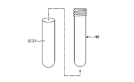
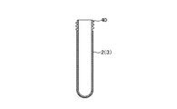
次に、図5Aに示すように、プリフォーム40の外側にチューブ状成形体2(3)をチューブ状成形体として装着する。チューブ状成形体2,3は、全体として有底円筒形状を有しており、円筒状の胴部と、ピンチオフにより閉塞された底部とを有している。図5Bに示すように、チューブ状成形体2(3)は、プリフォーム40の首部を除いてプリフォーム40全体を覆うように装着される。
チューブ状成形体2,3をプリフォーム40に装着した後、加熱処理を施すことも可能である。例えば50℃~100℃程度の加熱処理を施すことにより、チューブ状成形体2,3が熱収縮し、プリフォーム40とチューブ状成形体2,3の密着性を向上することができる。
次いで、チューブ状成形体2,3が装着されたプリフォーム40を予備加熱し、成形金型にセットする。予備加熱の温度はプリフォーム40の構成材料等に応じて適正な温度に設定すればよく、例えば90℃~130℃程度である。
予備加熱後、チューブ状成形体2,3が装着されたプリフォーム40を金型にセットする。金型は、成形する複合容器の形状に応じたキャビティを有するものであり、加熱により軟化したプリフォーム40内にエアブローすることにより、プリフォーム40及びチューブ状成形体2,3が延伸され、金型のキャビティ形状に賦形される。
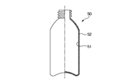
これにより、プリフォーム40が延伸されることにより形成される容器本体51の外側が、チューブ状成形体2,3が延伸されることにより形成される被覆層52で覆われた複合容器50が成形される。作製される複合容器50においては、チューブ状成形体2,3がブロー成形により形成されるものであるので、チューブ状成形体2,3を射出成形する場合等に比べて、製造コストを削減することができる。また、チューブ状成形体2,3は、ブロー成形により形成されるものではあるが、前述の通り厚さの均一性に優れるものであるので、複合容器50の被覆層52も厚さの均一性に優れたものとなり、高品質な複合容器50を成形することが可能である。
次に、複合容器の他の製造例について説明する。本実施形態のブロー成形方法(複合容器の製造方法)では、プリフォームの内側にチューブ状成形体を重ねた状態で二軸延伸ブローを行うことで、複合容器が作製される。本実施形態のブロー成形方法により複合容器を作製するには、先ず、プラスチック材料製のプリフォーム61を準備する。プリフォーム1の成形方法としては、例えば射出成形機を用いた射出成形や、押し出し成形等を挙げることができる。プリフォーム61の構成材料や層構成等は、先の実施形態におけるプリフォーム40と同様である。
次に、図6Aに示すように、プリフォーム61の内側にチューブ状成形体2(3)を装着する。チューブ状成形体2(3)は、全体として有底円筒形状を有しており、円筒状の胴部と、ピンチオフにより閉塞された底部とを有している。
チューブ状成形体2(3)の装填に際しては、プリフォーム61の首部や口部を含め、プリフォーム61の内面全体にチューブ状成形体2(3)が重なるように装着される。プリフォーム61の容器口部に対応する位置には、成形された容器にキャップを螺合するための螺子部やフランジ部等の凸部61aが形成されることがあるが、内面にはこれら螺子部やフランジ部等が突出形成されることはない。したがって、チューブ状成形体2をプリフォーム1の首部や口部にまで装填する上で、何ら支障となることはない。
前記チューブ状成形体2(3)は、先に説明したブロー成形により予め成形しておくが、装填時の摩擦軽減のため、その外面は、若干粗度が高い方がよい。例えば、チューブ状成形体2(3)を成形する際に用いる金型のキャビティ面に対してブラスト処理等を施しておけば、チューブ状成形体2(3)の外面を粗面とすることができる。
また、チューブ状成形体2(3)は、付与する機能性に応じて、適宜、材質や添加剤等を選定することができる。付与する機能性としては、例えば低吸着性、酸素バリア性、遮光性等が挙げられ、チューブ状成形体2(3)の成形材料として環状ポリオレフィン樹脂等を用いることで、低吸着性を実現することができる。あるいは、チューブ状成形体2の成形材料としてEVOH(エチレンビニルアルコール共重合体)を用いることで、酸素バリア性を付与することができる。遮光性を付与するためには、チューブ状成形体2(3)の成形材料に、着色材や紫外線吸収剤等を添加すればよい。
次いで、チューブ状成形体2(3)が装着されたプリフォーム61を予備加熱し、成形金型にセットする。予備加熱の温度はプリフォーム61の構成材料等に応じて適正な温度に設定すればよく、例えば90℃~130℃程度である。
予備加熱後、チューブ状成形体2(3)が装着されたプリフォーム61を金型にセットする。金型は、成形する複合容器の形状に応じたキャビティを有するものであり、加熱により軟化したプリフォーム61[チューブ状成形体2(3)]内にエアブローすることにより、プリフォーム61及びチューブ状成形体2(3)が延伸され、金型のキャビティ形状に賦形される。
これにより、プリフォーム1が延伸されて形成された容器本体71の内側が、チューブ状成形体2(3)が延伸されて形成された被覆層72で覆われる形で複合容器70が成形される。作製される複合容器70においては、チューブ状成形体2(3)がブロー成形により形成されるものであるので、チューブ状成形体2(3)を射出成形する場合等に比べて、製造コストを削減することができる。また、被覆層72は、複合容器70の首部や口部までも覆って形成されており、被覆層72が有する機能性を複合容器70全体に付与することができる。
なお、前述のブロー成形において、プリフォーム61とチューブ状成形体2(3)を重ねた状態で二軸延伸ブローを行う際に、チューブ状成形体2(3)の延伸に伴ってチューブ状成形体2(3)の開口端部がプリフォーム61内に後退してしまう可能性がある。チューブ状成形体2(3)の開口端部が後退してしまうと、プリフォーム61の内面全体をチューブ状成形体2(3)で覆うことができなくなる。
このような不都合を解消するためには、二軸延伸ブローに際して、例えばプリフォーム1の開口端部でチューブ状成形体2の開口端部を支持するように重ねればよい。図7は、プリフォーム61の開口端部でチューブ状成形体2の開口端部を支持させるための工程例を示すものである。この例では、チューブ状成形体2の開口端部2aをプリフォーム61の開口端部よりも延長して成形し、図7(a)に示すように、プリフォーム1の開口端部の形状に合わせた凹部を有する治具20でチューブ状成形体2の開口端部2aを折り返し、くせ付けを行う。これにより、図7(b)に示すように、プリフォーム61の開口端部の天面で、折り返されたチューブ状成形体2の開口端部2aを支持する形になり、チューブ状成形体2の開口端部2aがプリフォーム61内に引き込まれるのを防止することができる。
前述のようにチューブ状成形体2の開口端部2aの折り返しを行う場合、チューブ状成形体2の成形に際して、開口端部2aを外方へ湾曲するように成形することが好ましい。例えば、図8に示すように、チューブ状成形体2の開口端側において、開口径を拡大するように成形し、開口端部2aを外側に湾曲させて成形する。その後、一点鎖線位置で切断すれば、チューブ状成形体2の開口端部2aが外側に広がる形状となり、前記折り返しが容易なものとなる。
また、成形されるチューブ状成形体2の底部には、エア抜き孔2bを形成しておくことも好ましい形態である。チューブ状成形体2の底部にエア抜き孔2bを形成しておけば、チューブ状成形体2とプリフォーム61の間に空気が残存することがなくなり、チューブ状成形体2とプリフォーム61とが密着した状態で成形される。
さらに、チューブ状成形体2をブロー成形するに際しては、成形体の形態を複数のチューブ状成形体が連結された形態とし、両端のチューブ状成形体の連結されていない側の端部のみをピンチオフして、複数のチューブ状成形体を一括してブロー成形することが好ましい。これにより、周方向での厚さの均一性に優れたチューブ状成形体を成形することができ、チューブ状成形体を用いて成形される複合容器の信頼性を高めることが可能である。
本実施形態のブロー成形方法(複合容器の製造方法)は、前述の通りプリフォームの内側にチューブ状成形体を重ねた状態で二軸延伸ブローを行うものであり、これにより容器内面全体に機能性を付与することが可能である。また、いわゆる積層剥離容器を簡単に作製することが可能である。
以上、本発明を適用した実施形態についてを説明してきたが、本発明が前述の実施形態に限られるものでないことは言うまでもなく、本発明の要旨を逸脱しない範囲において、種々の変更を加えることが可能である。
例えば、先の実施形態では、製品を2個取りするようにしたが、前述の通り、3個取り以上とすることも可能である。3個取り以上とする場合、適用し得る製品の形態としては両端が開放されたものに限られるが、例えば前述のチューブ状成形体等において、容器の胴部のみを被覆する形態での利用が可能である。厚さの均一化の観点から言えば、連結する製品の個数が多いほど有利であるが、金型の大型化を招くこと等から、何個取りとするかは、製品形態や要求される性能、設備の規模等に応じて適宜選定すればよい。
また、先の実施形態では、プリフォームの外側や内側に装着されるチューブ状成形体の成形を例にして説明したが、製品としては係るチューブ状成形体に限定されるものではない。ブロー成形全般において、厚さの均一性が要求される場合に、本発明を適用することが可能である。
実施例
胴部が円筒形状で、一端が閉塞され、多端が開放されたチューブ状成形体をブロー成形した。成形したチューブ状成形体の胴部における設定肉厚は、0.5mmである。
胴部が円筒形状で、一端が閉塞され、多端が開放されたチューブ状成形体をブロー成形した。成形したチューブ状成形体の胴部における設定肉厚は、0.5mmである。
ブロー成形に際しては、先の実施形態で説明したように、2個取りとし、2つのチューブ状成形体を胴部よりも小径の連結部を介して連結された状態で一括して成形した。連結部はピンチオフされず、したがってピンチオフ(バリ噛み)されるのは、各チューブ状成形体の互いに連結されていない側の端部のみである。
比較例
実施例と同様、胴部が円筒形状で、一端が閉塞され、多端が開放されたチューブ状成形体をブロー成形した。成形したチューブ状成形体の胴部における設定肉厚は、実施例と同様、0.5mmである。
実施例と同様、胴部が円筒形状で、一端が閉塞され、多端が開放されたチューブ状成形体をブロー成形した。成形したチューブ状成形体の胴部における設定肉厚は、実施例と同様、0.5mmである。
ブロー成形は、いわゆる1個取りにて行った。したがって、ピンチオフ(バリ噛み)は、各製品(チューブ状成形体)において、閉塞される側の端部と、開放される側の端部の両方である。
評価
実施例及び比較例で成形したチューブ状成形体について、厚さの分布を測定した。測定箇所は、高さ方向において、10mm毎に設定した。図9は、製品(チューブ状成形体)Sの厚さ分布を測定した測定箇所を示す図であり、図中、1~5で示す7箇所について測定を行った。
実施例及び比較例で成形したチューブ状成形体について、厚さの分布を測定した。測定箇所は、高さ方向において、10mm毎に設定した。図9は、製品(チューブ状成形体)Sの厚さ分布を測定した測定箇所を示す図であり、図中、1~5で示す7箇所について測定を行った。
図10は、実施例で作製したチューブ状成形体の縦方向における厚さ分布を表したものである。図10から明らかなように、実施例で作製された製品(チューブ状成形体)では、各測定箇所において、パーティングライン位置(PL-1,PL-2)と、パーティングラインと直交する位置PL90-1での厚さの差は0.05mm以下である。
プリフォームの高さにおける上(開口側)から3分の2の範囲において、厚さのばらつきが、平均肉厚(3分の2の範囲の平均=約0.5mm)に対して、好ましくは、プラスマイナス10%の範囲内(約0.45~0.55mm)である。前記実施例は、この条件を満たしている。
同様に、比較例で作製されたチューブ状成形体(両端をピンチオフしてブロー成形されたチューブ状成形体)についても同様の測定を行ったところ、いずれの測定箇所においても周方向での厚さの差が0.1mmを越えており、前記条件を満たしていないことがわかった。
Claims (9)
- 押出機から押し出されるパリソンを一対の金型で挟み込んでブロー成形するブロー成形方法において、
成形体の形態を複数の製品が連結された形態とし、両端の製品の連結されていない側の端部のみをピンチオフして、前記複数の製品を一括してブロー成形することを特徴とするブロー成形方法。 - 2つの製品を一端側で連結した形態とし、各製品の連結されていない側の端部のみをピンチオフして、前記2つの製品を一括してブロー成形することを特徴とする請求項1記載のブロー成形方法。
- 連結される部分に吹き込み針を差し込み、エアーの吹き込みを行うことを特徴とする請求項1または2記載のブロー成形方法。
- 連結される部分を成形する金型部分が突出しており、当該突出する金型部分にパリソンを吸引して保持し、保持されたパリソンに吹き込み針を差し込むことを特徴とする請求項3に記載のブロー成形方法。
- 成形される製品が、プリフォームと重ねて成形されるチューブ状成形体であることを特徴とする請求項1から4のいずれか1項記載のブロー成形方法。
- 予め射出成形されたプリフォームの内側に、予めブロー成形されたチューブ状成形体を装填し、プリフォームの内側にチューブ状成形体を重ねた状態で二軸延伸ブロー成形を行うことを特徴とするブロー成形方法。
- 前記チューブ状成形体の装填に際し、チューブ成形体の開口端部を外側に折り返してプリフォームの開口端部に係止させることを特徴とする請求項6記載のブロー成形方法。
- 前記チューブ状成形体の成形に際して、開口端部における開口径を拡大するように、開口端部を外側に湾曲させて成形することを特徴とする請求項7記載のブロー成形方法。
- 前記チューブ状成形体は、請求項1から4のいずれか1項記載のブロー成形方法で成形されたものであることを特徴とする請求項6から8のいずれか1項記載のブロー成形方法。
Applications Claiming Priority (4)
| Application Number | Priority Date | Filing Date | Title |
|---|---|---|---|
| JP2015-193468 | 2015-09-30 | ||
| JP2015193468A JP6675068B2 (ja) | 2015-09-30 | 2015-09-30 | ブロー成形方法 |
| JP2015231999A JP6614440B2 (ja) | 2015-11-27 | 2015-11-27 | ブロー成形方法 |
| JP2015-231999 | 2015-11-27 |
Publications (1)
| Publication Number | Publication Date |
|---|---|
| WO2017057728A1 true WO2017057728A1 (ja) | 2017-04-06 |
Family
ID=58424065
Family Applications (1)
| Application Number | Title | Priority Date | Filing Date |
|---|---|---|---|
| PCT/JP2016/079116 Ceased WO2017057728A1 (ja) | 2015-09-30 | 2016-09-30 | ブロー成形方法 |
Country Status (1)
| Country | Link |
|---|---|
| WO (1) | WO2017057728A1 (ja) |
Citations (1)
| Publication number | Priority date | Publication date | Assignee | Title |
|---|---|---|---|---|
| JPS62233224A (ja) * | 1986-04-04 | 1987-10-13 | Toyo Seikan Kaisha Ltd | ポリエステル製3ピ−ス2メタルエンド缶の製造法 |
-
2016
- 2016-09-30 WO PCT/JP2016/079116 patent/WO2017057728A1/ja not_active Ceased
Patent Citations (1)
| Publication number | Priority date | Publication date | Assignee | Title |
|---|---|---|---|---|
| JPS62233224A (ja) * | 1986-04-04 | 1987-10-13 | Toyo Seikan Kaisha Ltd | ポリエステル製3ピ−ス2メタルエンド缶の製造法 |
Similar Documents
| Publication | Publication Date | Title |
|---|---|---|
| JP6876935B2 (ja) | 二重容器の成形方法 | |
| JP3820104B2 (ja) | ライナおよびプリフォーム | |
| JP6614440B2 (ja) | ブロー成形方法 | |
| CN101663143A (zh) | 具有由相同材料制成的内层和外层的一体吹塑内装袋容器、以及用于制造该内装袋容器的预制坯 | |
| BR112013029047B1 (pt) | recipiente de plástico com um gargalo cortado | |
| MX2012014910A (es) | Preforma para producir recipientes de plastico en un proceso de moldeo por soplado/estirado y metodo de produccion de la preforma. | |
| US9034446B2 (en) | Preform suitable for blow-molding into a final shaped container | |
| CN100402383C (zh) | 吹塑成形品 | |
| US20120056356A1 (en) | Blow Molding Process, Apparatus and Article | |
| US20070045216A1 (en) | Plastic container finish with structural rib | |
| US6884382B2 (en) | Stretched container threads and method of manufacture | |
| JP7197117B2 (ja) | 積層剥離ボトル及びその製造方法 | |
| US20070059462A1 (en) | Swage-forming of container threads | |
| JP2010188711A (ja) | 底付き筒状容器の製造方法 | |
| WO2016017059A1 (ja) | ブロー成形容器 | |
| JP6675068B2 (ja) | ブロー成形方法 | |
| US7303796B2 (en) | Preform assembly, container assembly and method of manufacture | |
| JP6443712B2 (ja) | ブロー成形プラスチックボトル | |
| JP2010000670A (ja) | 樹脂容器成形用プリフォーム | |
| JP7317453B2 (ja) | 容器の製造方法及び容器 | |
| JP2019130735A (ja) | プリフォームおよびプラスチックボトルの製造方法 | |
| US20020130445A1 (en) | Thermoplastic articles made from extrusion blow molded pre-forms | |
| CN205767422U (zh) | 吹塑机构 | |
| TH92915A (th) | รูปแบบล่วงหน้าสำหรับภาชนะบรรจุที่ผลิตโดยแบบเป่าหล่อยึด | |
| WO2016067511A1 (ja) | 液体ブロー成形用のプリフォーム |
Legal Events
| Date | Code | Title | Description |
|---|---|---|---|
| 121 | Ep: the epo has been informed by wipo that ep was designated in this application |
Ref document number: 16851897 Country of ref document: EP Kind code of ref document: A1 |
|
| NENP | Non-entry into the national phase |
Ref country code: DE |
|
| 122 | Ep: pct application non-entry in european phase |
Ref document number: 16851897 Country of ref document: EP Kind code of ref document: A1 |