WO2017057041A1 - Signal processing apparatus, signal processing method, and program - Google Patents
Signal processing apparatus, signal processing method, and program Download PDFInfo
- Publication number
- WO2017057041A1 WO2017057041A1 PCT/JP2016/077397 JP2016077397W WO2017057041A1 WO 2017057041 A1 WO2017057041 A1 WO 2017057041A1 JP 2016077397 W JP2016077397 W JP 2016077397W WO 2017057041 A1 WO2017057041 A1 WO 2017057041A1
- Authority
- WO
- WIPO (PCT)
- Prior art keywords
- target
- coordinate system
- signal processing
- correspondence
- detected
- Prior art date
Links
Images


Classifications
-
- G—PHYSICS
- G01—MEASURING; TESTING
- G01S—RADIO DIRECTION-FINDING; RADIO NAVIGATION; DETERMINING DISTANCE OR VELOCITY BY USE OF RADIO WAVES; LOCATING OR PRESENCE-DETECTING BY USE OF THE REFLECTION OR RERADIATION OF RADIO WAVES; ANALOGOUS ARRANGEMENTS USING OTHER WAVES
- G01S7/00—Details of systems according to groups G01S13/00, G01S15/00, G01S17/00
- G01S7/02—Details of systems according to groups G01S13/00, G01S15/00, G01S17/00 of systems according to group G01S13/00
- G01S7/40—Means for monitoring or calibrating
- G01S7/4004—Means for monitoring or calibrating of parts of a radar system
- G01S7/4026—Antenna boresight
-
- G—PHYSICS
- G01—MEASURING; TESTING
- G01C—MEASURING DISTANCES, LEVELS OR BEARINGS; SURVEYING; NAVIGATION; GYROSCOPIC INSTRUMENTS; PHOTOGRAMMETRY OR VIDEOGRAMMETRY
- G01C3/00—Measuring distances in line of sight; Optical rangefinders
- G01C3/02—Details
- G01C3/06—Use of electric means to obtain final indication
- G01C3/08—Use of electric radiation detectors
-
- G—PHYSICS
- G01—MEASURING; TESTING
- G01C—MEASURING DISTANCES, LEVELS OR BEARINGS; SURVEYING; NAVIGATION; GYROSCOPIC INSTRUMENTS; PHOTOGRAMMETRY OR VIDEOGRAMMETRY
- G01C3/00—Measuring distances in line of sight; Optical rangefinders
- G01C3/10—Measuring distances in line of sight; Optical rangefinders using a parallactic triangle with variable angles and a base of fixed length in the observation station, e.g. in the instrument
- G01C3/14—Measuring distances in line of sight; Optical rangefinders using a parallactic triangle with variable angles and a base of fixed length in the observation station, e.g. in the instrument with binocular observation at a single point, e.g. stereoscopic type
-
- G—PHYSICS
- G01—MEASURING; TESTING
- G01S—RADIO DIRECTION-FINDING; RADIO NAVIGATION; DETERMINING DISTANCE OR VELOCITY BY USE OF RADIO WAVES; LOCATING OR PRESENCE-DETECTING BY USE OF THE REFLECTION OR RERADIATION OF RADIO WAVES; ANALOGOUS ARRANGEMENTS USING OTHER WAVES
- G01S13/00—Systems using the reflection or reradiation of radio waves, e.g. radar systems; Analogous systems using reflection or reradiation of waves whose nature or wavelength is irrelevant or unspecified
- G01S13/86—Combinations of radar systems with non-radar systems, e.g. sonar, direction finder
- G01S13/867—Combination of radar systems with cameras
-
- G—PHYSICS
- G01—MEASURING; TESTING
- G01S—RADIO DIRECTION-FINDING; RADIO NAVIGATION; DETERMINING DISTANCE OR VELOCITY BY USE OF RADIO WAVES; LOCATING OR PRESENCE-DETECTING BY USE OF THE REFLECTION OR RERADIATION OF RADIO WAVES; ANALOGOUS ARRANGEMENTS USING OTHER WAVES
- G01S13/00—Systems using the reflection or reradiation of radio waves, e.g. radar systems; Analogous systems using reflection or reradiation of waves whose nature or wavelength is irrelevant or unspecified
- G01S13/88—Radar or analogous systems specially adapted for specific applications
- G01S13/93—Radar or analogous systems specially adapted for specific applications for anti-collision purposes
- G01S13/931—Radar or analogous systems specially adapted for specific applications for anti-collision purposes of land vehicles
-
- G—PHYSICS
- G01—MEASURING; TESTING
- G01S—RADIO DIRECTION-FINDING; RADIO NAVIGATION; DETERMINING DISTANCE OR VELOCITY BY USE OF RADIO WAVES; LOCATING OR PRESENCE-DETECTING BY USE OF THE REFLECTION OR RERADIATION OF RADIO WAVES; ANALOGOUS ARRANGEMENTS USING OTHER WAVES
- G01S7/00—Details of systems according to groups G01S13/00, G01S15/00, G01S17/00
- G01S7/02—Details of systems according to groups G01S13/00, G01S15/00, G01S17/00 of systems according to group G01S13/00
- G01S7/28—Details of pulse systems
- G01S7/285—Receivers
- G01S7/295—Means for transforming co-ordinates or for evaluating data, e.g. using computers
- G01S7/2955—Means for determining the position of the radar coordinate system for evaluating the position data of the target in another coordinate system
-
- G—PHYSICS
- G01—MEASURING; TESTING
- G01S—RADIO DIRECTION-FINDING; RADIO NAVIGATION; DETERMINING DISTANCE OR VELOCITY BY USE OF RADIO WAVES; LOCATING OR PRESENCE-DETECTING BY USE OF THE REFLECTION OR RERADIATION OF RADIO WAVES; ANALOGOUS ARRANGEMENTS USING OTHER WAVES
- G01S7/00—Details of systems according to groups G01S13/00, G01S15/00, G01S17/00
- G01S7/02—Details of systems according to groups G01S13/00, G01S15/00, G01S17/00 of systems according to group G01S13/00
- G01S7/40—Means for monitoring or calibrating
- G01S7/4052—Means for monitoring or calibrating by simulation of echoes
- G01S7/4082—Means for monitoring or calibrating by simulation of echoes using externally generated reference signals, e.g. via remote reflector or transponder
- G01S7/4086—Means for monitoring or calibrating by simulation of echoes using externally generated reference signals, e.g. via remote reflector or transponder in a calibrating environment, e.g. anechoic chamber
-
- G—PHYSICS
- G06—COMPUTING; CALCULATING OR COUNTING
- G06T—IMAGE DATA PROCESSING OR GENERATION, IN GENERAL
- G06T7/00—Image analysis
- G06T7/70—Determining position or orientation of objects or cameras
- G06T7/73—Determining position or orientation of objects or cameras using feature-based methods
- G06T7/74—Determining position or orientation of objects or cameras using feature-based methods involving reference images or patches
-
- G—PHYSICS
- G06—COMPUTING; CALCULATING OR COUNTING
- G06V—IMAGE OR VIDEO RECOGNITION OR UNDERSTANDING
- G06V20/00—Scenes; Scene-specific elements
- G06V20/50—Context or environment of the image
- G06V20/56—Context or environment of the image exterior to a vehicle by using sensors mounted on the vehicle
- G06V20/58—Recognition of moving objects or obstacles, e.g. vehicles or pedestrians; Recognition of traffic objects, e.g. traffic signs, traffic lights or roads
-
- G—PHYSICS
- G06—COMPUTING; CALCULATING OR COUNTING
- G06V—IMAGE OR VIDEO RECOGNITION OR UNDERSTANDING
- G06V20/00—Scenes; Scene-specific elements
- G06V20/60—Type of objects
- G06V20/64—Three-dimensional objects
- G06V20/647—Three-dimensional objects by matching two-dimensional images to three-dimensional objects
-
- G—PHYSICS
- G08—SIGNALLING
- G08G—TRAFFIC CONTROL SYSTEMS
- G08G1/00—Traffic control systems for road vehicles
- G08G1/16—Anti-collision systems
-
- G—PHYSICS
- G08—SIGNALLING
- G08G—TRAFFIC CONTROL SYSTEMS
- G08G1/00—Traffic control systems for road vehicles
- G08G1/16—Anti-collision systems
- G08G1/166—Anti-collision systems for active traffic, e.g. moving vehicles, pedestrians, bikes
-
- H—ELECTRICITY
- H04—ELECTRIC COMMUNICATION TECHNIQUE
- H04N—PICTORIAL COMMUNICATION, e.g. TELEVISION
- H04N13/00—Stereoscopic video systems; Multi-view video systems; Details thereof
- H04N13/20—Image signal generators
- H04N13/204—Image signal generators using stereoscopic image cameras
- H04N13/239—Image signal generators using stereoscopic image cameras using two 2D image sensors having a relative position equal to or related to the interocular distance
-
- H—ELECTRICITY
- H04—ELECTRIC COMMUNICATION TECHNIQUE
- H04N—PICTORIAL COMMUNICATION, e.g. TELEVISION
- H04N13/00—Stereoscopic video systems; Multi-view video systems; Details thereof
- H04N13/20—Image signal generators
- H04N13/204—Image signal generators using stereoscopic image cameras
- H04N13/246—Calibration of cameras
-
- B—PERFORMING OPERATIONS; TRANSPORTING
- B60—VEHICLES IN GENERAL
- B60R—VEHICLES, VEHICLE FITTINGS, OR VEHICLE PARTS, NOT OTHERWISE PROVIDED FOR
- B60R21/00—Arrangements or fittings on vehicles for protecting or preventing injuries to occupants or pedestrians in case of accidents or other traffic risks
-
- G—PHYSICS
- G01—MEASURING; TESTING
- G01S—RADIO DIRECTION-FINDING; RADIO NAVIGATION; DETERMINING DISTANCE OR VELOCITY BY USE OF RADIO WAVES; LOCATING OR PRESENCE-DETECTING BY USE OF THE REFLECTION OR RERADIATION OF RADIO WAVES; ANALOGOUS ARRANGEMENTS USING OTHER WAVES
- G01S15/00—Systems using the reflection or reradiation of acoustic waves, e.g. sonar systems
- G01S15/86—Combinations of sonar systems with lidar systems; Combinations of sonar systems with systems not using wave reflection
-
- G—PHYSICS
- G01—MEASURING; TESTING
- G01S—RADIO DIRECTION-FINDING; RADIO NAVIGATION; DETERMINING DISTANCE OR VELOCITY BY USE OF RADIO WAVES; LOCATING OR PRESENCE-DETECTING BY USE OF THE REFLECTION OR RERADIATION OF RADIO WAVES; ANALOGOUS ARRANGEMENTS USING OTHER WAVES
- G01S15/00—Systems using the reflection or reradiation of acoustic waves, e.g. sonar systems
- G01S15/88—Sonar systems specially adapted for specific applications
- G01S15/93—Sonar systems specially adapted for specific applications for anti-collision purposes
- G01S15/931—Sonar systems specially adapted for specific applications for anti-collision purposes of land vehicles
-
- G—PHYSICS
- G01—MEASURING; TESTING
- G01S—RADIO DIRECTION-FINDING; RADIO NAVIGATION; DETERMINING DISTANCE OR VELOCITY BY USE OF RADIO WAVES; LOCATING OR PRESENCE-DETECTING BY USE OF THE REFLECTION OR RERADIATION OF RADIO WAVES; ANALOGOUS ARRANGEMENTS USING OTHER WAVES
- G01S17/00—Systems using the reflection or reradiation of electromagnetic waves other than radio waves, e.g. lidar systems
- G01S17/86—Combinations of lidar systems with systems other than lidar, radar or sonar, e.g. with direction finders
-
- G—PHYSICS
- G01—MEASURING; TESTING
- G01S—RADIO DIRECTION-FINDING; RADIO NAVIGATION; DETERMINING DISTANCE OR VELOCITY BY USE OF RADIO WAVES; LOCATING OR PRESENCE-DETECTING BY USE OF THE REFLECTION OR RERADIATION OF RADIO WAVES; ANALOGOUS ARRANGEMENTS USING OTHER WAVES
- G01S17/00—Systems using the reflection or reradiation of electromagnetic waves other than radio waves, e.g. lidar systems
- G01S17/88—Lidar systems specially adapted for specific applications
- G01S17/93—Lidar systems specially adapted for specific applications for anti-collision purposes
- G01S17/931—Lidar systems specially adapted for specific applications for anti-collision purposes of land vehicles
-
- G—PHYSICS
- G01—MEASURING; TESTING
- G01S—RADIO DIRECTION-FINDING; RADIO NAVIGATION; DETERMINING DISTANCE OR VELOCITY BY USE OF RADIO WAVES; LOCATING OR PRESENCE-DETECTING BY USE OF THE REFLECTION OR RERADIATION OF RADIO WAVES; ANALOGOUS ARRANGEMENTS USING OTHER WAVES
- G01S13/00—Systems using the reflection or reradiation of radio waves, e.g. radar systems; Analogous systems using reflection or reradiation of waves whose nature or wavelength is irrelevant or unspecified
- G01S13/88—Radar or analogous systems specially adapted for specific applications
- G01S13/93—Radar or analogous systems specially adapted for specific applications for anti-collision purposes
- G01S13/931—Radar or analogous systems specially adapted for specific applications for anti-collision purposes of land vehicles
- G01S2013/9323—Alternative operation using light waves
-
- G—PHYSICS
- G01—MEASURING; TESTING
- G01S—RADIO DIRECTION-FINDING; RADIO NAVIGATION; DETERMINING DISTANCE OR VELOCITY BY USE OF RADIO WAVES; LOCATING OR PRESENCE-DETECTING BY USE OF THE REFLECTION OR RERADIATION OF RADIO WAVES; ANALOGOUS ARRANGEMENTS USING OTHER WAVES
- G01S13/00—Systems using the reflection or reradiation of radio waves, e.g. radar systems; Analogous systems using reflection or reradiation of waves whose nature or wavelength is irrelevant or unspecified
- G01S13/88—Radar or analogous systems specially adapted for specific applications
- G01S13/93—Radar or analogous systems specially adapted for specific applications for anti-collision purposes
- G01S13/931—Radar or analogous systems specially adapted for specific applications for anti-collision purposes of land vehicles
- G01S2013/9324—Alternative operation using ultrasonic waves
-
- G—PHYSICS
- G01—MEASURING; TESTING
- G01S—RADIO DIRECTION-FINDING; RADIO NAVIGATION; DETERMINING DISTANCE OR VELOCITY BY USE OF RADIO WAVES; LOCATING OR PRESENCE-DETECTING BY USE OF THE REFLECTION OR RERADIATION OF RADIO WAVES; ANALOGOUS ARRANGEMENTS USING OTHER WAVES
- G01S7/00—Details of systems according to groups G01S13/00, G01S15/00, G01S17/00
- G01S7/48—Details of systems according to groups G01S13/00, G01S15/00, G01S17/00 of systems according to group G01S17/00
- G01S7/497—Means for monitoring or calibrating
- G01S7/4972—Alignment of sensor
-
- G—PHYSICS
- G01—MEASURING; TESTING
- G01S—RADIO DIRECTION-FINDING; RADIO NAVIGATION; DETERMINING DISTANCE OR VELOCITY BY USE OF RADIO WAVES; LOCATING OR PRESENCE-DETECTING BY USE OF THE REFLECTION OR RERADIATION OF RADIO WAVES; ANALOGOUS ARRANGEMENTS USING OTHER WAVES
- G01S7/00—Details of systems according to groups G01S13/00, G01S15/00, G01S17/00
- G01S7/52—Details of systems according to groups G01S13/00, G01S15/00, G01S17/00 of systems according to group G01S15/00
- G01S7/52004—Means for monitoring or calibrating
-
- G—PHYSICS
- G06—COMPUTING; CALCULATING OR COUNTING
- G06T—IMAGE DATA PROCESSING OR GENERATION, IN GENERAL
- G06T2207/00—Indexing scheme for image analysis or image enhancement
- G06T2207/10—Image acquisition modality
- G06T2207/10004—Still image; Photographic image
- G06T2207/10012—Stereo images
-
- G—PHYSICS
- G06—COMPUTING; CALCULATING OR COUNTING
- G06T—IMAGE DATA PROCESSING OR GENERATION, IN GENERAL
- G06T2207/00—Indexing scheme for image analysis or image enhancement
- G06T2207/10—Image acquisition modality
- G06T2207/10032—Satellite or aerial image; Remote sensing
- G06T2207/10044—Radar image
-
- G—PHYSICS
- G06—COMPUTING; CALCULATING OR COUNTING
- G06T—IMAGE DATA PROCESSING OR GENERATION, IN GENERAL
- G06T2207/00—Indexing scheme for image analysis or image enhancement
- G06T2207/30—Subject of image; Context of image processing
- G06T2207/30248—Vehicle exterior or interior
- G06T2207/30252—Vehicle exterior; Vicinity of vehicle
- G06T2207/30261—Obstacle
Landscapes
- Engineering & Computer Science (AREA)
- Remote Sensing (AREA)
- Radar, Positioning & Navigation (AREA)
- Physics & Mathematics (AREA)
- General Physics & Mathematics (AREA)
- Computer Networks & Wireless Communication (AREA)
- Electromagnetism (AREA)
- Multimedia (AREA)
- Theoretical Computer Science (AREA)
- Signal Processing (AREA)
- Computer Vision & Pattern Recognition (AREA)
- Radar Systems Or Details Thereof (AREA)
- Measurement Of Optical Distance (AREA)
- Length Measuring Devices By Optical Means (AREA)
- Traffic Control Systems (AREA)
Abstract
Description
1.物体検出システムの構成例
2.対応検出処理の詳細説明
3.運用時キャリブレーション処理
4.キャリブレーション処理の処理フロー
5.出荷時キャリブレーション処理におけるターゲットの例
6.運用時キャリブレーション処理におけるターゲットの例
7.コンピュータ構成例 Hereinafter, modes for carrying out the present technology (hereinafter referred to as embodiments) will be described. The description will be given in the following order.
1. 1. Configuration example of
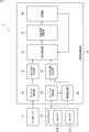
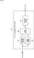
図1は、本技術を適用した物体検出システムの構成例を示すブロック図である。 <1. Configuration example of object detection system>
FIG. 1 is a block diagram illustrating a configuration example of an object detection system to which the present technology is applied.
Pcam(k)=R・PMMW(k)+V ・・・・・・・(1) The position /
P cam (k) = R · P MMW (k) + V (1)
<第1の対応検出処理>
次に、対応検出部36が行う、ターゲットの事前配置情報を用いた第1の対応検出処理についてさらに詳しく説明する。 <2. Detailed explanation of correspondence detection processing>
<First correspondence detection process>
Next, the first correspondence detection process using the target pre-arrangement information performed by the


上述した第1の対応検出処理は、ターゲットの事前配置情報を用いた検出方法であるが、ターゲットの事前配置情報を用いずに、レーダ3次元座標系で検出されたターゲットと、カメラ3次元座標系で検出されたターゲットとの対応関係を検出することもできる。 <Second correspondence detection process>
The first correspondence detection process described above is a detection method that uses the target pre-position information, but the target detected by the radar three-dimensional coordinate system and the camera three-dimensional coordinates without using the target pre-position information. It is also possible to detect the correspondence with the target detected by the system.
次に、運用時キャリブレーション処理について説明する。 <3. Calibration during operation>
Next, the operation calibration process will be described.
図16乃至図21を参照しながら、運用時キャリブレーション処理について具体的に説明する。 <Specific example of calibration processing during operation>
The operation calibration process will be specifically described with reference to FIGS.
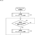
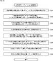
次に、図22のフローチャートを参照して、信号処理装置13により実行されるキャリブレーション処理について説明する。 <4. Calibration process flow>
Next, the calibration process executed by the
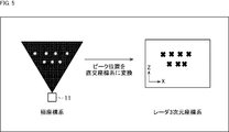
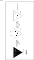
図25は、出荷時キャリブレーション処理において用いることができるターゲットのその他の例を示している。 <5. Example of target in factory calibration process>
FIG. 25 shows another example of a target that can be used in the calibration process at the time of shipment.
次に、運用時キャリブレーション処理において用いることができるターゲットのその他の例について説明する。 <6. Examples of targets for calibration during operation>
Next, other examples of targets that can be used in the calibration process during operation will be described.
上述したキャリブレーション処理を含む一連の処理は、ハードウエアにより実行することもできるし、ソフトウエアにより実行することもできる。一連の処理をソフトウエアにより実行する場合には、そのソフトウエアを構成するプログラムが、コンピュータにインストールされる。ここで、コンピュータには、専用のハードウエアに組み込まれているコンピュータや、各種のプログラムをインストールすることで、各種の機能を実行することが可能な、例えば汎用のパーソナルコンピュータなどが含まれる。 <7. Computer configuration example>
The series of processes including the calibration process described above can be executed by hardware or can be executed by software. When a series of processing is executed by software, a program constituting the software is installed in the computer. Here, the computer includes, for example, a general-purpose personal computer capable of executing various functions by installing various programs by installing a computer incorporated in dedicated hardware.
(1)
ステレオカメラにより撮像されたステレオ画像から、第1の座標系におけるターゲットの3次元位置を算出する第1位置算出部と、
横方向または縦方向の少なくとも一方の位置情報と、奥行き方向の位置情報とを取得できるセンサのセンサ信号から、第2の座標系における前記ターゲットの3次元位置を算出する第2位置算出部と、
前記第1の座標系上の前記ターゲットと、前記第2の座標系上の前記ターゲットとの対応関係を検出する対応検出部と、
検出された前記対応関係に基づいて、前記第1の座標系と前記第2の座標系の位置関係情報を推定する位置関係情報推定部と
を備える信号処理装置。
(2)
前記対応検出部は、前記第1の座標系上の前記ターゲットと前記第2の座標系上の前記ターゲットのそれぞれを前記ターゲットの事前配置情報と照合し、前記ターゲットを特定した上で、前記対応関係を検出する
前記(1)に記載の信号処理装置。
(3)
前記対応検出部は、前記第1の座標系上の前記ターゲットの3次元位置と前記第2の座標系上の前記ターゲットの3次元位置を重畳させ、最近傍に配置されたターゲットどうしを対応させ、前記対応関係を検出する
前記(1)または(2)に記載の信号処理装置。
(4)
前記第1位置算出部は、動きが検出された前記ターゲットの3次元位置を算出し、
前記第2位置算出部は、動きが検出された前記ターゲットの3次元位置を算出する
前記(1)乃至(3)のいずれかに記載の信号処理装置。
(5)
前記第1位置算出部は、1フレーム以上のステレオ画像から複数の前記ターゲットの3次元位置を算出し、
前記第2位置算出部は、1フレーム以上のセンサ信号から複数の前記ターゲットの3次元位置を算出し、
前記対応検出部は、複数の前記ターゲットについて対応関係を検出する
前記(1)乃至(4)のいずれかに記載の信号処理装置。
(6)
前記第1位置算出部は、1フレームのステレオ画像から複数の前記ターゲットの3次元位置を算出し、
前記第2位置算出部は、1フレームのセンサ信号から複数の前記ターゲットの3次元位置を算出する
前記(5)に記載の信号処理装置。
(7)
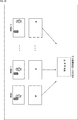
前記第1位置算出部及び前記第2位置算出部により算出された前記ターゲットの3次元位置を記憶する記憶部をさらに備え、
前記対応検出部は、所定数以上の前記ターゲットの3次元位置が前記記憶部に蓄積された場合に、前記対応関係の検出を開始する
前記(1)乃至(6)のいずれかに記載の信号処理装置。
(8)
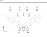
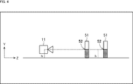
前記ターゲットは、前記奥行き方向の位置が異なる位置に複数配置される
前記(1)乃至(7)のいずれかに記載の信号処理装置。
(9)
前記ターゲットは、前記横方向の位置が異なる位置に複数配置される
前記(1)乃至(8)のいずれかに記載の信号処理装置。
(10)
前記ターゲットは、同じ高さ位置に複数配置される
前記(1)乃至(9)のいずれかに記載の信号処理装置。
(11)
前記ターゲットは、前記ステレオカメラから見て、重ならない位置に複数配置される
前記(1)乃至(10)のいずれかに記載の信号処理装置。
(12)
前記ターゲットは、人である
前記(1)乃至(10)のいずれかに記載の信号処理装置。
(13)
前記ターゲットは、所定のテクスチャを有する物体である
前記(1)乃至(10)のいずれかに記載の信号処理装置。
(14)
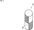
前記ターゲットは、ポール状の物体である
前記(1)乃至(10)のいずれかに記載の信号処理装置。
(15)
前記第1の座標系と前記第2の座標系の位置関係情報は、回転行列と並進ベクトルである
前記(1)乃至(14)のいずれかに記載の信号処理装置。
(16)
前記センサは、ミリ波レーダである
前記(1)乃至(15)のいずれかに記載の信号処理装置。
(17)
ステレオカメラにより撮像されたステレオ画像から、第1の座標系におけるターゲットの3次元位置を算出し、
横方向または縦方向の少なくとも一方の位置情報と、奥行き方向の位置情報とを取得できるセンサのセンサ信号から、第2の座標系における前記ターゲットの3次元位置を算出し、
前記第1の座標系上の前記ターゲットと、前記第2の座標系上の前記ターゲットとの対応関係を検出し、
検出された前記対応関係に基づいて、前記第1の座標系と前記第2の座標系の位置関係情報を推定する
ステップを含む信号処理方法。
(18)
コンピュータに、
ステレオカメラにより撮像されたステレオ画像から、第1の座標系におけるターゲットの3次元位置を算出し、
横方向または縦方向の少なくとも一方の位置情報と、奥行き方向の位置情報とを取得できるセンサのセンサ信号から、第2の座標系における前記ターゲットの3次元位置を算出し、
前記第1の座標系上の前記ターゲットと、前記第2の座標系上の前記ターゲットとの対応関係を検出し、
検出された前記対応関係に基づいて、前記第1の座標系と前記第2の座標系の位置関係情報を推定する
ステップを含む処理を実行させるためのプログラム。 In addition, this technique can also take the following structures.
(1)
A first position calculation unit that calculates a three-dimensional position of a target in a first coordinate system from a stereo image captured by a stereo camera;
A second position calculation unit that calculates a three-dimensional position of the target in a second coordinate system from a sensor signal of a sensor that can acquire position information in at least one of the horizontal direction and the vertical direction and position information in the depth direction;
A correspondence detection unit for detecting a correspondence relationship between the target on the first coordinate system and the target on the second coordinate system;
A signal processing apparatus comprising: a positional relationship information estimation unit that estimates positional relationship information between the first coordinate system and the second coordinate system based on the detected correspondence.
(2)
The correspondence detection unit collates each of the target on the first coordinate system and the target on the second coordinate system with the pre-arrangement information of the target, specifies the target, and then performs the correspondence The signal processing device according to (1), wherein a relationship is detected.
(3)
The correspondence detection unit superimposes the three-dimensional position of the target on the first coordinate system and the three-dimensional position of the target on the second coordinate system, and associates the targets arranged closest to each other. The signal processing device according to (1) or (2), wherein the correspondence relationship is detected.
(4)
The first position calculation unit calculates a three-dimensional position of the target where the movement is detected,
The signal processing device according to any one of (1) to (3), wherein the second position calculation unit calculates a three-dimensional position of the target from which a motion is detected.
(5)
The first position calculation unit calculates a three-dimensional position of the plurality of targets from a stereo image of one frame or more,
The second position calculation unit calculates three-dimensional positions of the plurality of targets from sensor signals of one frame or more,
The signal processing apparatus according to any one of (1) to (4), wherein the correspondence detection unit detects correspondences for a plurality of the targets.
(6)
The first position calculation unit calculates a three-dimensional position of the plurality of targets from one frame of a stereo image,
The signal processing apparatus according to (5), wherein the second position calculation unit calculates a three-dimensional position of the plurality of targets from one frame of sensor signals.
(7)
A storage unit that stores the three-dimensional position of the target calculated by the first position calculation unit and the second position calculation unit;
The correspondence detection unit starts detection of the correspondence relationship when a predetermined number or more of three-dimensional positions of the target are accumulated in the storage unit. The signal according to any one of (1) to (6) Processing equipment.
(8)
The signal processing device according to any one of (1) to (7), wherein a plurality of the targets are arranged at different positions in the depth direction.
(9)
The signal processing device according to any one of (1) to (8), wherein a plurality of the targets are arranged at different positions in the lateral direction.
(10)
The signal processing device according to any one of (1) to (9), wherein a plurality of the targets are arranged at the same height position.
(11)
The signal processing device according to any one of (1) to (10), wherein a plurality of the targets are arranged at positions that do not overlap when viewed from the stereo camera.
(12)
The signal processing apparatus according to any one of (1) to (10), wherein the target is a person.
(13)
The signal processing apparatus according to any one of (1) to (10), wherein the target is an object having a predetermined texture.
(14)
The signal processing apparatus according to any one of (1) to (10), wherein the target is a pole-shaped object.
(15)
The signal processing device according to any one of (1) to (14), wherein the positional relationship information between the first coordinate system and the second coordinate system is a rotation matrix and a translation vector.
(16)
The signal processing device according to any one of (1) to (15), wherein the sensor is a millimeter wave radar.
(17)
Calculating the three-dimensional position of the target in the first coordinate system from the stereo image captured by the stereo camera;
Calculating a three-dimensional position of the target in the second coordinate system from a sensor signal of a sensor capable of acquiring position information in at least one of the horizontal direction and the vertical direction and position information in the depth direction;
Detecting a correspondence relationship between the target on the first coordinate system and the target on the second coordinate system;
A signal processing method including a step of estimating positional relationship information between the first coordinate system and the second coordinate system based on the detected correspondence.
(18)
On the computer,
Calculating the three-dimensional position of the target in the first coordinate system from the stereo image captured by the stereo camera;
Calculating a three-dimensional position of the target in the second coordinate system from a sensor signal of a sensor capable of acquiring position information in at least one of the horizontal direction and the vertical direction and position information in the depth direction;
Detecting a correspondence relationship between the target on the first coordinate system and the target on the second coordinate system;
A program for executing processing including a step of estimating positional relationship information between the first coordinate system and the second coordinate system based on the detected correspondence.
Claims (18)
- ステレオカメラにより撮像されたステレオ画像から、第1の座標系におけるターゲットの3次元位置を算出する第1位置算出部と、
横方向または縦方向の少なくとも一方の位置情報と、奥行き方向の位置情報とを取得できるセンサのセンサ信号から、第2の座標系における前記ターゲットの3次元位置を算出する第2位置算出部と、
前記第1の座標系上の前記ターゲットと、前記第2の座標系上の前記ターゲットとの対応関係を検出する対応検出部と、
検出された前記対応関係に基づいて、前記第1の座標系と前記第2の座標系の位置関係情報を推定する位置関係情報推定部と
を備える信号処理装置。 A first position calculation unit that calculates a three-dimensional position of a target in a first coordinate system from a stereo image captured by a stereo camera;
A second position calculation unit that calculates a three-dimensional position of the target in a second coordinate system from a sensor signal of a sensor that can acquire position information in at least one of the horizontal direction and the vertical direction and position information in the depth direction;
A correspondence detection unit for detecting a correspondence relationship between the target on the first coordinate system and the target on the second coordinate system;
A signal processing apparatus comprising: a positional relationship information estimation unit that estimates positional relationship information between the first coordinate system and the second coordinate system based on the detected correspondence. - 前記対応検出部は、前記第1の座標系上の前記ターゲットと前記第2の座標系上の前記ターゲットのそれぞれを前記ターゲットの事前配置情報と照合し、前記ターゲットを特定した上で、前記対応関係を検出する
請求項1に記載の信号処理装置。 The correspondence detection unit collates each of the target on the first coordinate system and the target on the second coordinate system with the pre-arrangement information of the target, specifies the target, and then performs the correspondence The signal processing device according to claim 1, wherein a relationship is detected. - 前記対応検出部は、前記第1の座標系上の前記ターゲットの3次元位置と前記第2の座標系上の前記ターゲットの3次元位置を重畳させ、最近傍に配置されたターゲットどうしを対応させ、前記対応関係を検出する
請求項1に記載の信号処理装置。 The correspondence detection unit superimposes the three-dimensional position of the target on the first coordinate system and the three-dimensional position of the target on the second coordinate system, and associates the targets arranged closest to each other. The signal processing device according to claim 1, wherein the correspondence relationship is detected. - 前記第1位置算出部は、動きが検出された前記ターゲットの3次元位置を算出し、
前記第2位置算出部は、動きが検出された前記ターゲットの3次元位置を算出する
請求項1に記載の信号処理装置。 The first position calculation unit calculates a three-dimensional position of the target where the movement is detected,
The signal processing apparatus according to claim 1, wherein the second position calculation unit calculates a three-dimensional position of the target from which movement is detected. - 前記第1位置算出部は、1フレーム以上のステレオ画像から複数の前記ターゲットの3次元位置を算出し、
前記第2位置算出部は、1フレーム以上のセンサ信号から複数の前記ターゲットの3次元位置を算出し、
前記対応検出部は、複数の前記ターゲットについて対応関係を検出する
請求項1に記載の信号処理装置。 The first position calculation unit calculates a three-dimensional position of the plurality of targets from a stereo image of one frame or more,
The second position calculation unit calculates three-dimensional positions of the plurality of targets from sensor signals of one frame or more,
The signal processing device according to claim 1, wherein the correspondence detection unit detects correspondences for the plurality of targets. - 前記第1位置算出部は、1フレームのステレオ画像から複数の前記ターゲットの3次元位置を算出し、
前記第2位置算出部は、1フレームのセンサ信号から複数の前記ターゲットの3次元位置を算出する
請求項5に記載の信号処理装置。 The first position calculation unit calculates a three-dimensional position of the plurality of targets from one frame of a stereo image,
The signal processing apparatus according to claim 5, wherein the second position calculation unit calculates a three-dimensional position of the plurality of targets from one frame of sensor signals. - 前記第1位置算出部及び前記第2位置算出部により算出された前記ターゲットの3次元位置を記憶する記憶部をさらに備え、
前記対応検出部は、所定数以上の前記ターゲットの3次元位置が前記記憶部に蓄積された場合に、前記対応関係の検出を開始する
請求項1に記載の信号処理装置。 A storage unit that stores the three-dimensional position of the target calculated by the first position calculation unit and the second position calculation unit;
The signal processing apparatus according to claim 1, wherein the correspondence detection unit starts detection of the correspondence relationship when a predetermined number or more of three-dimensional positions of the target are accumulated in the storage unit. - 前記ターゲットは、前記奥行き方向の位置が異なる位置に複数配置される
請求項1に記載の信号処理装置。 The signal processing device according to claim 1, wherein a plurality of the targets are arranged at different positions in the depth direction. - 前記ターゲットは、前記横方向の位置が異なる位置に複数配置される
請求項1に記載の信号処理装置。 The signal processing device according to claim 1, wherein a plurality of the targets are arranged at different positions in the lateral direction. - 前記ターゲットは、同じ高さ位置に複数配置される
請求項1に記載の信号処理装置。 The signal processing device according to claim 1, wherein a plurality of the targets are arranged at the same height position. - 前記ターゲットは、前記ステレオカメラから見て、重ならない位置に複数配置される
請求項1に記載の信号処理装置。 The signal processing device according to claim 1, wherein a plurality of the targets are arranged at positions where they do not overlap when viewed from the stereo camera. - 前記ターゲットは、人である
請求項1に記載の信号処理装置。 The signal processing apparatus according to claim 1, wherein the target is a person. - 前記ターゲットは、所定のテクスチャを有する物体である
請求項1に記載の信号処理装置。 The signal processing apparatus according to claim 1, wherein the target is an object having a predetermined texture. - 前記ターゲットは、ポール状の物体である
請求項1に記載の信号処理装置。 The signal processing apparatus according to claim 1, wherein the target is a pole-shaped object. - 前記第1の座標系と前記第2の座標系の位置関係情報は、回転行列と並進ベクトルである
請求項1に記載の信号処理装置。 The signal processing apparatus according to claim 1, wherein the positional relationship information between the first coordinate system and the second coordinate system is a rotation matrix and a translation vector. - 前記センサは、ミリ波レーダである
請求項1に記載の信号処理装置。 The signal processing apparatus according to claim 1, wherein the sensor is a millimeter wave radar. - ステレオカメラにより撮像されたステレオ画像から、第1の座標系におけるターゲットの3次元位置を算出し、
横方向または縦方向の少なくとも一方の位置情報と、奥行き方向の位置情報とを取得できるセンサのセンサ信号から、第2の座標系における前記ターゲットの3次元位置を算出し、
前記第1の座標系上の前記ターゲットと、前記第2の座標系上の前記ターゲットとの対応関係を検出し、
検出された前記対応関係に基づいて、前記第1の座標系と前記第2の座標系の位置関係情報を推定する
ステップを含む信号処理方法。 Calculating the three-dimensional position of the target in the first coordinate system from the stereo image captured by the stereo camera;
Calculating a three-dimensional position of the target in the second coordinate system from a sensor signal of a sensor capable of acquiring position information in at least one of the horizontal direction and the vertical direction and position information in the depth direction;
Detecting a correspondence relationship between the target on the first coordinate system and the target on the second coordinate system;
A signal processing method including a step of estimating positional relationship information between the first coordinate system and the second coordinate system based on the detected correspondence. - コンピュータに、
ステレオカメラにより撮像されたステレオ画像から、第1の座標系におけるターゲットの3次元位置を算出し、
横方向または縦方向の少なくとも一方の位置情報と、奥行き方向の位置情報とを取得できるセンサのセンサ信号から、第2の座標系における前記ターゲットの3次元位置を算出し、
前記第1の座標系上の前記ターゲットと、前記第2の座標系上の前記ターゲットとの対応関係を検出し、
検出された前記対応関係に基づいて、前記第1の座標系と前記第2の座標系の位置関係情報を推定する
ステップを含む処理を実行させるためのプログラム。 On the computer,
Calculating the three-dimensional position of the target in the first coordinate system from the stereo image captured by the stereo camera;
Calculating a three-dimensional position of the target in the second coordinate system from a sensor signal of a sensor capable of acquiring position information in at least one of the horizontal direction and the vertical direction and position information in the depth direction;
Detecting a correspondence relationship between the target on the first coordinate system and the target on the second coordinate system;
A program for executing processing including a step of estimating positional relationship information between the first coordinate system and the second coordinate system based on the detected correspondence.
Priority Applications (5)
| Application Number | Priority Date | Filing Date | Title |
|---|---|---|---|
| US15/762,136 US10908257B2 (en) | 2015-09-30 | 2016-09-16 | Signal processing apparatus, signal processing method, and program |
| JP2017543132A JP6825569B2 (en) | 2015-09-30 | 2016-09-16 | Signal processor, signal processing method, and program |
| EP16851215.0A EP3358368A4 (en) | 2015-09-30 | 2016-09-16 | Signal processing apparatus, signal processing method, and program |
| CN201680055407.1A CN108139475A (en) | 2015-09-30 | 2016-09-16 | Signal handling equipment, signal processing method and program |
| US17/139,290 US11719788B2 (en) | 2015-09-30 | 2020-12-31 | Signal processing apparatus, signal processing method, and program |
Applications Claiming Priority (2)
| Application Number | Priority Date | Filing Date | Title |
|---|---|---|---|
| JP2015194134 | 2015-09-30 | ||
| JP2015-194134 | 2015-09-30 |
Related Child Applications (2)
| Application Number | Title | Priority Date | Filing Date |
|---|---|---|---|
| US15/762,136 A-371-Of-International US10908257B2 (en) | 2015-09-30 | 2016-09-16 | Signal processing apparatus, signal processing method, and program |
| US17/139,290 Continuation US11719788B2 (en) | 2015-09-30 | 2020-12-31 | Signal processing apparatus, signal processing method, and program |
Publications (1)
| Publication Number | Publication Date |
|---|---|
| WO2017057041A1 true WO2017057041A1 (en) | 2017-04-06 |
Family
ID=58427496
Family Applications (1)
| Application Number | Title | Priority Date | Filing Date |
|---|---|---|---|
| PCT/JP2016/077397 WO2017057041A1 (en) | 2015-09-30 | 2016-09-16 | Signal processing apparatus, signal processing method, and program |
Country Status (5)
| Country | Link |
|---|---|
| US (2) | US10908257B2 (en) |
| EP (1) | EP3358368A4 (en) |
| JP (1) | JP6825569B2 (en) |
| CN (1) | CN108139475A (en) |
| WO (1) | WO2017057041A1 (en) |
Cited By (7)
| Publication number | Priority date | Publication date | Assignee | Title |
|---|---|---|---|---|
| JP2017223680A (en) * | 2016-12-30 | 2017-12-21 | 東軟集団股▲分▼有限公司 | Method and device for generating target detection information, and equipment |
| JP2020030466A (en) * | 2018-08-20 | 2020-02-27 | 株式会社Soken | Object detection device |
| KR20200052589A (en) * | 2018-11-07 | 2020-05-15 | 현대자동차주식회사 | Apparatus and method for removing misrecognition of front vehicle and vehicle including the same |
| JP2020079781A (en) * | 2018-09-07 | 2020-05-28 | バイドゥ オンライン ネットワーク テクノロジー (ベイジン) カンパニー リミテッド | Method and apparatus for determining relative pose, device and medium |
| WO2020116206A1 (en) * | 2018-12-07 | 2020-06-11 | ソニーセミコンダクタソリューションズ株式会社 | Information processing device, information processing method, and program |
| JP2020530555A (en) * | 2017-07-26 | 2020-10-22 | ロベルト・ボッシュ・ゲゼルシャフト・ミト・ベシュレンクテル・ハフツングRobert Bosch Gmbh | Devices and methods for recognizing the position of an object |
| WO2022044634A1 (en) * | 2020-08-26 | 2022-03-03 | 株式会社デンソー | Object recognition device, moving body collision prevention device, and object recognition method |
Families Citing this family (28)
| Publication number | Priority date | Publication date | Assignee | Title |
|---|---|---|---|---|
| JP6825569B2 (en) | 2015-09-30 | 2021-02-03 | ソニー株式会社 | Signal processor, signal processing method, and program |
| JP6660751B2 (en) * | 2016-02-04 | 2020-03-11 | 日立オートモティブシステムズ株式会社 | Imaging device |
| JP6194520B1 (en) * | 2016-06-24 | 2017-09-13 | 三菱電機株式会社 | Object recognition device, object recognition method, and automatic driving system |
| US11067996B2 (en) | 2016-09-08 | 2021-07-20 | Siemens Industry Software Inc. | Event-driven region of interest management |
| US10481243B2 (en) * | 2016-10-31 | 2019-11-19 | Aptiv Technologies Limited | Automated vehicle radar system with self-calibration |
| JP2019015553A (en) * | 2017-07-05 | 2019-01-31 | ソニーセミコンダクタソリューションズ株式会社 | Information processing device, information processing method, and solid-state imaging device |
| US20190120934A1 (en) * | 2017-10-19 | 2019-04-25 | GM Global Technology Operations LLC | Three-dimensional alignment of radar and camera sensors |
| CN110044371A (en) * | 2018-01-16 | 2019-07-23 | 华为技术有限公司 | A kind of method and vehicle locating device of vehicle location |
| US11041941B2 (en) * | 2018-02-26 | 2021-06-22 | Steradian Semiconductors Private Limited | Method and device for calibrating a radar object detection system |
| CN110609274B (en) * | 2018-06-15 | 2022-07-01 | 杭州海康威视数字技术股份有限公司 | Distance measurement method, device and system |
| KR20200028648A (en) * | 2018-09-07 | 2020-03-17 | 삼성전자주식회사 | Method for adjusting an alignment model for sensors and an electronic device performing the method |
| TWI734932B (en) * | 2018-09-17 | 2021-08-01 | 為昇科科技股份有限公司 | Radar detection angle caliberation system and method thereof |
| US20220404488A1 (en) * | 2018-10-01 | 2022-12-22 | Kpit Technologies Limited | Perception sensors based fusion system for vehicle control and method thereof |
| EP3907721A4 (en) * | 2019-01-02 | 2022-03-09 | Panasonic Intellectual Property Corporation of America | Information processing device, information processing method, and program |
| JP7238422B2 (en) * | 2019-01-22 | 2023-03-14 | 株式会社リコー | distance measuring method, distance measuring device, in-vehicle device, moving body, distance measuring system |
| JP2020118567A (en) * | 2019-01-24 | 2020-08-06 | ソニーセミコンダクタソリューションズ株式会社 | Distance measurement device, on-vehicle system, and distance measurement method |
| US10942267B2 (en) * | 2019-06-17 | 2021-03-09 | Advanced New Technologies Co., Ltd. | Video object processing |
| CN110263700B (en) * | 2019-06-17 | 2021-04-27 | 创新先进技术有限公司 | Video processing method, device and equipment and video monitoring system |
| CN112208529B (en) * | 2019-07-09 | 2022-08-02 | 毫末智行科技有限公司 | Perception system for object detection, driving assistance method, and unmanned device |
| CN110597390B (en) * | 2019-09-12 | 2022-05-20 | Oppo广东移动通信有限公司 | Control method, electronic device, and storage medium |
| US11892559B2 (en) * | 2019-12-18 | 2024-02-06 | Rohde & Schwarz Gmbh & Co. Kg | Radar calibration system and method for moving a radar calibration target along a desired movement path |
| CN111060904B (en) * | 2019-12-25 | 2022-03-15 | 中国汽车技术研究中心有限公司 | Blind area monitoring method based on millimeter wave and vision fusion perception |
| US20210325520A1 (en) * | 2020-04-17 | 2021-10-21 | Velodyne Lidar, Inc. | Systems and Methods for Calibrating a LIDAR Device |
| US20220113419A1 (en) * | 2020-10-13 | 2022-04-14 | Waymo, LLC | LIDAR Based Stereo Camera Correction |
| KR102484691B1 (en) * | 2021-03-15 | 2023-01-05 | 주식회사 바이다 | Vehicle detection system and vehicle detection method using stereo camera and radar |
| US20230204749A1 (en) * | 2021-12-23 | 2023-06-29 | Gm Cruise Holdings Llc | Radar sensor processing chain |
| CN114509762A (en) * | 2022-02-15 | 2022-05-17 | 南京慧尔视智能科技有限公司 | Data processing method, device, equipment and medium |
| EP4310534A1 (en) * | 2022-07-21 | 2024-01-24 | Inxpect S.p.A. | Target detection in world reference system |
Citations (4)
| Publication number | Priority date | Publication date | Assignee | Title |
|---|---|---|---|---|
| JP2007218738A (en) * | 2006-02-16 | 2007-08-30 | Kumamoto Univ | Calibration device, target detection device, and calibration method |
| JP2010151682A (en) * | 2008-12-25 | 2010-07-08 | Topcon Corp | Laser scanner, laser scanner measuring system, calibration method of laser scanner measuring system, and target for calibration |
| US20110122257A1 (en) * | 2009-11-25 | 2011-05-26 | Honeywell International Inc. | Geolocation of objects in an area of interest |
| JP2014153211A (en) * | 2013-02-08 | 2014-08-25 | Furukawa Electric Co Ltd:The | Periphery monitoring system and misalignment detection method of periphery monitoring system |
Family Cites Families (21)
| Publication number | Priority date | Publication date | Assignee | Title |
|---|---|---|---|---|
| JP3212218B2 (en) * | 1994-05-26 | 2001-09-25 | 三菱電機株式会社 | Obstacle detection device for vehicles |
| US6859705B2 (en) * | 2001-09-21 | 2005-02-22 | Ford Global Technologies, Llc | Method for operating a pre-crash sensing system with object classifier in a vehicle having a countermeasure system |
| DE602004016520D1 (en) * | 2003-07-11 | 2008-10-23 | Toyota Motor Co Ltd | IMPACT SAFETY VEHICLE CONTROL SYSTEM |
| JP3918791B2 (en) * | 2003-09-11 | 2007-05-23 | トヨタ自動車株式会社 | Object detection device |
| JP2006011570A (en) * | 2004-06-23 | 2006-01-12 | Daihatsu Motor Co Ltd | Camera calibration method and camera calibration device |
| JP2006252473A (en) * | 2005-03-14 | 2006-09-21 | Toshiba Corp | Obstacle detector, calibration device, calibration method and calibration program |
| WO2006123615A1 (en) * | 2005-05-19 | 2006-11-23 | Olympus Corporation | Distance measuring apparatus, distance measuring method and distance measuring program |
| JP4304517B2 (en) * | 2005-11-09 | 2009-07-29 | トヨタ自動車株式会社 | Object detection device |
| US20070182623A1 (en) * | 2006-02-03 | 2007-08-09 | Shuqing Zeng | Method and apparatus for on-vehicle calibration and orientation of object-tracking systems |
| JP4595833B2 (en) * | 2006-02-24 | 2010-12-08 | トヨタ自動車株式会社 | Object detection device |
| JP2008116357A (en) * | 2006-11-06 | 2008-05-22 | Toyota Motor Corp | Object detector |
| US8855848B2 (en) * | 2007-06-05 | 2014-10-07 | GM Global Technology Operations LLC | Radar, lidar and camera enhanced methods for vehicle dynamics estimation |
| JP5145585B2 (en) * | 2007-06-08 | 2013-02-20 | 国立大学法人 熊本大学 | Target detection device |
| US20090292468A1 (en) * | 2008-03-25 | 2009-11-26 | Shunguang Wu | Collision avoidance method and system using stereo vision and radar sensor fusion |
| JP4434296B1 (en) * | 2008-09-05 | 2010-03-17 | トヨタ自動車株式会社 | Object detection device |
| JP5632762B2 (en) * | 2011-01-25 | 2014-11-26 | パナソニック株式会社 | POSITIONING INFORMATION FORMING DEVICE, DETECTING DEVICE, AND POSITIONING INFORMATION FORMING METHOD |
| JP5503578B2 (en) * | 2011-03-10 | 2014-05-28 | パナソニック株式会社 | Object detection apparatus and object detection method |
| US8970425B2 (en) * | 2011-06-09 | 2015-03-03 | Sony Corporation | Radar apparatus and method |
| US9405006B2 (en) * | 2012-09-03 | 2016-08-02 | Toyota Jidosha Kabushiki Kaisha | Collision determination device and collision determination method |
| CN104318561B (en) * | 2014-10-22 | 2017-05-03 | 上海理工大学 | Method for detecting vehicle motion information based on integration of binocular stereoscopic vision and optical flow |
| JP6825569B2 (en) | 2015-09-30 | 2021-02-03 | ソニー株式会社 | Signal processor, signal processing method, and program |
-
2016
- 2016-09-16 JP JP2017543132A patent/JP6825569B2/en active Active
- 2016-09-16 US US15/762,136 patent/US10908257B2/en active Active
- 2016-09-16 EP EP16851215.0A patent/EP3358368A4/en not_active Withdrawn
- 2016-09-16 WO PCT/JP2016/077397 patent/WO2017057041A1/en active Application Filing
- 2016-09-16 CN CN201680055407.1A patent/CN108139475A/en active Pending
-
2020
- 2020-12-31 US US17/139,290 patent/US11719788B2/en active Active
Patent Citations (4)
| Publication number | Priority date | Publication date | Assignee | Title |
|---|---|---|---|---|
| JP2007218738A (en) * | 2006-02-16 | 2007-08-30 | Kumamoto Univ | Calibration device, target detection device, and calibration method |
| JP2010151682A (en) * | 2008-12-25 | 2010-07-08 | Topcon Corp | Laser scanner, laser scanner measuring system, calibration method of laser scanner measuring system, and target for calibration |
| US20110122257A1 (en) * | 2009-11-25 | 2011-05-26 | Honeywell International Inc. | Geolocation of objects in an area of interest |
| JP2014153211A (en) * | 2013-02-08 | 2014-08-25 | Furukawa Electric Co Ltd:The | Periphery monitoring system and misalignment detection method of periphery monitoring system |
Non-Patent Citations (1)
| Title |
|---|
| See also references of EP3358368A4 * |
Cited By (14)
| Publication number | Priority date | Publication date | Assignee | Title |
|---|---|---|---|---|
| US10217005B2 (en) | 2016-12-30 | 2019-02-26 | Neusoft Corporation | Method, apparatus and device for generating target detection information |
| JP2017223680A (en) * | 2016-12-30 | 2017-12-21 | 東軟集団股▲分▼有限公司 | Method and device for generating target detection information, and equipment |
| JP2020530555A (en) * | 2017-07-26 | 2020-10-22 | ロベルト・ボッシュ・ゲゼルシャフト・ミト・ベシュレンクテル・ハフツングRobert Bosch Gmbh | Devices and methods for recognizing the position of an object |
| US11313961B2 (en) | 2017-07-26 | 2022-04-26 | Robert Bosch Gmbh | Method and device for identifying the height of an object |
| JP2020030466A (en) * | 2018-08-20 | 2020-02-27 | 株式会社Soken | Object detection device |
| JP7135579B2 (en) | 2018-08-20 | 2022-09-13 | 株式会社Soken | Object detection device |
| US11372101B2 (en) | 2018-09-07 | 2022-06-28 | Apollo Intelligent Driving Technology (Beijing) Co., Ltd. | Method and apparatus for determining relative pose, device and medium |
| JP2020079781A (en) * | 2018-09-07 | 2020-05-28 | バイドゥ オンライン ネットワーク テクノロジー (ベイジン) カンパニー リミテッド | Method and apparatus for determining relative pose, device and medium |
| JP7222854B2 (en) | 2018-09-07 | 2023-02-15 | アポロ インテリジェント ドライビング テクノロジー(ペキン)カンパニー リミテッド | Relative position and orientation determination method, apparatus, equipment and medium |
| KR20200052589A (en) * | 2018-11-07 | 2020-05-15 | 현대자동차주식회사 | Apparatus and method for removing misrecognition of front vehicle and vehicle including the same |
| KR102524293B1 (en) | 2018-11-07 | 2023-04-21 | 현대자동차주식회사 | Apparatus and method for removing misrecognition of front vehicle and vehicle including the same |
| WO2020116206A1 (en) * | 2018-12-07 | 2020-06-11 | ソニーセミコンダクタソリューションズ株式会社 | Information processing device, information processing method, and program |
| WO2022044634A1 (en) * | 2020-08-26 | 2022-03-03 | 株式会社デンソー | Object recognition device, moving body collision prevention device, and object recognition method |
| JP7359107B2 (en) | 2020-08-26 | 2023-10-11 | 株式会社デンソー | Object recognition devices, mobile collision prevention devices, and vehicles |
Also Published As
| Publication number | Publication date |
|---|---|
| US20180267142A1 (en) | 2018-09-20 |
| JPWO2017057041A1 (en) | 2018-08-09 |
| EP3358368A4 (en) | 2019-03-13 |
| US11719788B2 (en) | 2023-08-08 |
| JP6825569B2 (en) | 2021-02-03 |
| CN108139475A (en) | 2018-06-08 |
| US20210124013A1 (en) | 2021-04-29 |
| US10908257B2 (en) | 2021-02-02 |
| EP3358368A1 (en) | 2018-08-08 |
Similar Documents
| Publication | Publication Date | Title |
|---|---|---|
| WO2017057041A1 (en) | Signal processing apparatus, signal processing method, and program | |
| CN111191600B (en) | Obstacle detection method, obstacle detection device, computer device, and storage medium | |
| US10937231B2 (en) | Systems and methods for updating a high-resolution map based on binocular images | |
| CN111448591B (en) | System and method for locating a vehicle in poor lighting conditions | |
| CA3028653C (en) | Methods and systems for color point cloud generation | |
| AU2018282302B2 (en) | Integrated sensor calibration in natural scenes | |
| EP3283843B1 (en) | Generating 3-dimensional maps of a scene using passive and active measurements | |
| TWI722355B (en) | Systems and methods for correcting a high-definition map based on detection of obstructing objects | |
| WO2017159382A1 (en) | Signal processing device and signal processing method | |
| US7103213B2 (en) | Method and apparatus for classifying an object | |
| US20170285161A1 (en) | Object Detection Using Radar And Vision Defined Image Detection Zone | |
| US11061122B2 (en) | High-definition map acquisition system | |
| JP2012075060A (en) | Image processing device, and imaging device using the same | |
| WO2020140164A1 (en) | Systems and methods for updating a high-definition map | |
| WO2020133415A1 (en) | Systems and methods for constructing a high-definition map based on landmarks | |
| JP2019128350A (en) | Image processing method, image processing device, on-vehicle device, moving body and system | |
| AU2018102199A4 (en) | Methods and systems for color point cloud generation | |
| US20240098231A1 (en) | Image processing device, image processing method, and computer-readable medium | |
| Paracchini et al. | Accurate omnidirectional multi-camera embedded structure from motion | |
| CN117953046A (en) | Data processing method, device, controller, vehicle and storage medium | |
| Li et al. | Automatic Surround Camera Calibration Method in Road Scene for Self-driving Car | |
| CN115511975A (en) | Distance measurement method of monocular camera and computer program product |
Legal Events
| Date | Code | Title | Description |
|---|---|---|---|
| 121 | Ep: the epo has been informed by wipo that ep was designated in this application |
Ref document number: 16851215 Country of ref document: EP Kind code of ref document: A1 |
|
| ENP | Entry into the national phase |
Ref document number: 2017543132 Country of ref document: JP Kind code of ref document: A |
|
| WWE | Wipo information: entry into national phase |
Ref document number: 15762136 Country of ref document: US |
|
| NENP | Non-entry into the national phase |
Ref country code: DE |
|
| WWE | Wipo information: entry into national phase |
Ref document number: 2016851215 Country of ref document: EP |