WO2017056688A1 - Monitoring system and vehicle control device - Google Patents
Monitoring system and vehicle control device Download PDFInfo
- Publication number
- WO2017056688A1 WO2017056688A1 PCT/JP2016/072582 JP2016072582W WO2017056688A1 WO 2017056688 A1 WO2017056688 A1 WO 2017056688A1 JP 2016072582 W JP2016072582 W JP 2016072582W WO 2017056688 A1 WO2017056688 A1 WO 2017056688A1
- Authority
- WO
- WIPO (PCT)
- Prior art keywords
- control unit
- control device
- monitoring
- sub
- vehicle
- Prior art date
Links
Images


Classifications
-
- F—MECHANICAL ENGINEERING; LIGHTING; HEATING; WEAPONS; BLASTING
- F16—ENGINEERING ELEMENTS AND UNITS; GENERAL MEASURES FOR PRODUCING AND MAINTAINING EFFECTIVE FUNCTIONING OF MACHINES OR INSTALLATIONS; THERMAL INSULATION IN GENERAL
- F16H—GEARING
- F16H61/00—Control functions within control units of change-speed- or reversing-gearings for conveying rotary motion ; Control of exclusively fluid gearing, friction gearing, gearings with endless flexible members or other particular types of gearing
- F16H61/12—Detecting malfunction or potential malfunction, e.g. fail safe; Circumventing or fixing failures
-
- G—PHYSICS
- G06—COMPUTING; CALCULATING OR COUNTING
- G06F—ELECTRIC DIGITAL DATA PROCESSING
- G06F11/00—Error detection; Error correction; Monitoring
- G06F11/07—Responding to the occurrence of a fault, e.g. fault tolerance
- G06F11/16—Error detection or correction of the data by redundancy in hardware
- G06F11/18—Error detection or correction of the data by redundancy in hardware using passive fault-masking of the redundant circuits
- G06F11/182—Error detection or correction of the data by redundancy in hardware using passive fault-masking of the redundant circuits based on mutual exchange of the output between redundant processing components
-
- B—PERFORMING OPERATIONS; TRANSPORTING
- B60—VEHICLES IN GENERAL
- B60R—VEHICLES, VEHICLE FITTINGS, OR VEHICLE PARTS, NOT OTHERWISE PROVIDED FOR
- B60R16/00—Electric or fluid circuits specially adapted for vehicles and not otherwise provided for; Arrangement of elements of electric or fluid circuits specially adapted for vehicles and not otherwise provided for
- B60R16/02—Electric or fluid circuits specially adapted for vehicles and not otherwise provided for; Arrangement of elements of electric or fluid circuits specially adapted for vehicles and not otherwise provided for electric constitutive elements
-
- G—PHYSICS
- G05—CONTROLLING; REGULATING
- G05B—CONTROL OR REGULATING SYSTEMS IN GENERAL; FUNCTIONAL ELEMENTS OF SUCH SYSTEMS; MONITORING OR TESTING ARRANGEMENTS FOR SUCH SYSTEMS OR ELEMENTS
- G05B9/00—Safety arrangements
- G05B9/02—Safety arrangements electric
- G05B9/03—Safety arrangements electric with multiple-channel loop, i.e. redundant control systems
-
- G—PHYSICS
- G07—CHECKING-DEVICES
- G07C—TIME OR ATTENDANCE REGISTERS; REGISTERING OR INDICATING THE WORKING OF MACHINES; GENERATING RANDOM NUMBERS; VOTING OR LOTTERY APPARATUS; ARRANGEMENTS, SYSTEMS OR APPARATUS FOR CHECKING NOT PROVIDED FOR ELSEWHERE
- G07C5/00—Registering or indicating the working of vehicles
- G07C5/08—Registering or indicating performance data other than driving, working, idle, or waiting time, with or without registering driving, working, idle or waiting time
- G07C5/0808—Diagnosing performance data
-
- F—MECHANICAL ENGINEERING; LIGHTING; HEATING; WEAPONS; BLASTING
- F16—ENGINEERING ELEMENTS AND UNITS; GENERAL MEASURES FOR PRODUCING AND MAINTAINING EFFECTIVE FUNCTIONING OF MACHINES OR INSTALLATIONS; THERMAL INSULATION IN GENERAL
- F16H—GEARING
- F16H61/00—Control functions within control units of change-speed- or reversing-gearings for conveying rotary motion ; Control of exclusively fluid gearing, friction gearing, gearings with endless flexible members or other particular types of gearing
- F16H61/12—Detecting malfunction or potential malfunction, e.g. fail safe; Circumventing or fixing failures
- F16H2061/1208—Detecting malfunction or potential malfunction, e.g. fail safe; Circumventing or fixing failures with diagnostic check cycles; Monitoring of failures
-
- G—PHYSICS
- G05—CONTROLLING; REGULATING
- G05B—CONTROL OR REGULATING SYSTEMS IN GENERAL; FUNCTIONAL ELEMENTS OF SUCH SYSTEMS; MONITORING OR TESTING ARRANGEMENTS FOR SUCH SYSTEMS OR ELEMENTS
- G05B19/00—Programme-control systems
- G05B19/02—Programme-control systems electric
- G05B19/04—Programme control other than numerical control, i.e. in sequence controllers or logic controllers
- G05B19/042—Programme control other than numerical control, i.e. in sequence controllers or logic controllers using digital processors
- G05B19/0421—Multiprocessor system
-
- G—PHYSICS
- G05—CONTROLLING; REGULATING
- G05B—CONTROL OR REGULATING SYSTEMS IN GENERAL; FUNCTIONAL ELEMENTS OF SUCH SYSTEMS; MONITORING OR TESTING ARRANGEMENTS FOR SUCH SYSTEMS OR ELEMENTS
- G05B19/00—Programme-control systems
- G05B19/02—Programme-control systems electric
- G05B19/04—Programme control other than numerical control, i.e. in sequence controllers or logic controllers
- G05B19/042—Programme control other than numerical control, i.e. in sequence controllers or logic controllers using digital processors
- G05B19/0428—Safety, monitoring
-
- G—PHYSICS
- G05—CONTROLLING; REGULATING
- G05B—CONTROL OR REGULATING SYSTEMS IN GENERAL; FUNCTIONAL ELEMENTS OF SUCH SYSTEMS; MONITORING OR TESTING ARRANGEMENTS FOR SUCH SYSTEMS OR ELEMENTS
- G05B2219/00—Program-control systems
- G05B2219/10—Plc systems
- G05B2219/14—Plc safety
- G05B2219/14014—Redundant processors and I-O
-
- G—PHYSICS
- G05—CONTROLLING; REGULATING
- G05B—CONTROL OR REGULATING SYSTEMS IN GENERAL; FUNCTIONAL ELEMENTS OF SUCH SYSTEMS; MONITORING OR TESTING ARRANGEMENTS FOR SUCH SYSTEMS OR ELEMENTS
- G05B2219/00—Program-control systems
- G05B2219/10—Plc systems
- G05B2219/14—Plc safety
- G05B2219/14104—Fault masking, redundant module is selected, fault will not propagate
-
- G—PHYSICS
- G06—COMPUTING; CALCULATING OR COUNTING
- G06F—ELECTRIC DIGITAL DATA PROCESSING
- G06F11/00—Error detection; Error correction; Monitoring
- G06F11/07—Responding to the occurrence of a fault, e.g. fault tolerance
- G06F11/16—Error detection or correction of the data by redundancy in hardware
- G06F11/18—Error detection or correction of the data by redundancy in hardware using passive fault-masking of the redundant circuits
- G06F11/187—Voting techniques
Definitions
- An object of the present invention is to prevent a malfunction of a control target due to a microcomputer failure in an electronic control device, and to prevent the vehicle from being disabled. Even when it is determined that the microcomputer is abnormal, the electronic control device operates normally.
- the present invention relates to fail-safe system technology that can be applied to systems with high safety requirements.
- the abnormality detection means between the CPUs for the electronic control device having a multi-CPU configuration as shown in Patent Document 1 determines only by the watchdog pulse, that is, detects the abnormality only by the CPU function for calculating the watchdog pulse.
- the entire CPU function has not been diagnosed, and it is difficult to say that it is an optimal countermeasure in terms of comprehensiveness of diagnosis.
- the present invention can detect a failure of the microcomputer in the electronic control unit of the automatic transmission for vehicles equipped with the electric actuator with a small system configuration without changing the configuration of the current electronic control unit, and can shift to the fail-safe state.
- An object is to provide a monitoring system and a vehicle control device.
- An electronic control device for a vehicle including an electric actuator according to claims 1 and 11 includes: a main control unit; a sub-control unit that monitors the main control unit; a failure part specifying unit that specifies a failure part based on a monitoring result; A first vehicle control device including a control signal switching unit that switches a control signal according to a part identification result, and a second vehicle control device configured separately from the first vehicle control device.
- the monitoring system is characterized in that mutual monitoring is performed between a control unit provided in the second vehicle control device and a main control unit and a sub control unit of the first vehicle control device.
- the sub-control unit of the vehicle electronic control device including the electric actuator according to claim 2 or 12 monitors the main control unit based on a calculation signal output from the main control unit, and detects an abnormality in the main control unit. In some cases, abnormal information is transmitted to the failure part specifying means.
- the vehicle control device including the electric actuator according to claims 3 and 13 and the second vehicle control device are connected by communication means such as CAN communication, for example.
- a monitoring system for a vehicle control device including an electric actuator according to claims 4 and 14 is connected to the second vehicle control device by communication means such as CAN communication, and is provided in the second vehicle control device.
- the control unit transmits a diagnostic signal by communication means to the main control unit or the sub control unit, and confirms a reply from the main control unit or the sub control unit, so that the abnormality of the main control unit and the sub control unit It is characterized by detecting.
- the monitoring system for a vehicle control device including the electric actuator according to claims 5 and 15 is configured to monitor the main control unit or the sub control unit by a control unit provided in the second vehicle control device. When the error is detected, the abnormality information is transmitted to the failure part specifying means.
- the failure part specifying means of the vehicle control device including the electric actuator according to claims 6 and 16 is configured to obtain monitoring results from the main control unit, the sub control unit, and the control unit provided in the second vehicle control device.
- the failure part is identified by majority decision, and the determination result is transmitted to the control signal switching means.
- the control signal switching means of the vehicle control device provided with the electric actuator according to claim 7 or 17 is a control signal output from the main control unit based on a determination result from the failure part specifying means, It is characterized by switching to one of the control signals output from the sub-control unit.
- the control unit provided in the second vehicle control device according to claim 8 or 18 performs control on the control target thereafter when an abnormality of the main control unit or the sub control unit is detected.
- the main control unit or the sub control unit is monitored.
- the sub-control unit of the vehicle control device provided with the electric actuator according to claim 9 or 19 is abnormal with respect to the control unit provided in the second vehicle control device when the abnormality of the main control unit is detected.
- the control unit transmits a signal, and the control unit monitors the sub-control unit when an abnormal signal is received.
- the main control unit of the vehicle control device including the electric actuator according to claim 10 and 20 monitors the sub-control unit, and one of the main control unit and the sub-control unit is abnormal in the other control unit.
- an abnormality signal is detected, an abnormality signal is transmitted to the control unit provided in the second vehicle control device, and the control unit monitors one control unit when the abnormality signal is received. Yes.
- a master CPU (for control) and a slave CPU (for monitoring), both of which are configurations of a general existing electronic control unit, have both CPUs have a monitoring function, and a mutual monitoring configuration.
- another electronic control device is also a monitoring device via the network, a monitoring configuration between the three parties can be achieved, and the fault site (CPU) can be accurately identified.
- An example of the monitoring system in ATCU which shows embodiment of this invention.
- the steering function may be lost, leading to a serious accident. That is, when a failure of the electronic control device occurs, the failure of the steering function is not allowed, and the normal process needs to be executed reliably, not the fail-safe process. For this reason, the electronic control device for the electric power steering has a redundant configuration with a triple system or more, and by constantly monitoring each other, the failed electronic control device can be reliably detected, and the failed electronic control device is disconnected from the monitoring loop. This ensures the steering function.
- the electronic control device is a redundant configuration of a triple system or more
- the mounting area of the electronic control device is three times the normal, so that a large number of electronic control components are mounted in recent times. It will inevitably be a problem in vehicles.
- the cost is the same.
- redundancy of the electronic control unit is one means. In the field, even if the function of the electronic control device fails, there is no possibility that it will lead to a serious accident. Therefore, it is difficult to say that it is an optimal countermeasure in consideration of cost effectiveness.
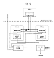
- FIG. 1 shows an example of a monitoring system in an electronic control unit (hereinafter referred to as ATCU) according to claim 1 for an automatic continuously variable transmission equipped with an electric actuator.
- ATCU electronice control unit
- the ATCU is composed of two CPUs including a main CPU that controls the electric actuator and a sub CPU that monitors the arithmetic function of the main CPU.
- the input to the ATCU includes a rotation pulse signal generated along with the rotation of the primary pulley and the secondary pulley, and other information input via a network such as CAN communication as the target engine speed necessary for calculating the target gear ratio.
- motor position information from the electric actuator that controls the target engine torque and the gear ratio Based on these pieces of information, the main CPU calculates the target drive torque to determine the gear ratio, that is, the control amount of the electric actuator.
- the calculated control amount needs to be converted into a signal for driving the electric actuator, that is, the electric motor, and the main CPU corrects environmental disturbances such as the motor power supply voltage and temperature, and then the control signal is sent to the driver circuit. And the electric actuator is controlled.
- the main CPU performing the control as described above needs to monitor whether each function is operating normally. Therefore, the sub CPU transmits a plurality of function monitoring problems to the main CPU. For the received problem, the main CPU calculates an answer corresponding to the problem using all operators defined in the CPU, and returns the answer to the sub CPU. The sub CPU stores an answer value that cannot be calculated unless the function (operator) that should be supposed is normal, and the main CPU operates normally by checking the answer value with the answer data received from the main CPU. Determine whether or not.
- the monitoring logic mounted on the sub CPU is also mounted on the main CPU so that mutual monitoring is performed between the main CPU and the sub CPU.
- the monitoring electronic control unit (hereinafter referred to as monitoring CU) is configured separately from the ATCU, and is connected to the ATCU via a communication line.
- the monitoring CU monitors whether or not the main CPU and sub CPU of the ATCU are operating normally.
- the monitoring method is the same as the mutual monitoring between the main CPU and the sub CPU, and is performed between the main CPU and the monitoring CU and between the sub CPU and the monitoring CU.
- the main CPU, the sub CPU, and the monitoring CU are configured to perform mutual monitoring, and the failure part can be specified.
- the monitoring results are collected in the failure part specifying means, and the failure part is specified.
- the monitoring results of the main CPU and the sub CPU are collated. At this time, if neither has detected an abnormality, the ATCU determines that it is normal, shifts to normal control, and outputs a control signal.
- the monitoring results of the main CPU and the sub CPU are different, that is, when one of the results determined to be abnormal is transmitted to the failure location specifying means, the monitoring result of the monitoring CU is referred to.
- the CPU that makes the same judgment as the monitoring result in the monitoring CU is assumed to be normal.
- the main CPU and the sub CPU exclude the monitoring CU from mutual monitoring.
- the failure part specifying means instructs the control signal switching means to switch the control signal based on the monitoring result received from the main CPU, the sub CPU, and the monitoring CU. Specifically, assuming that the main CPU is normal in the initial state, the main CPU calculates a control amount for the electric actuator and outputs a control signal. At this time, the sub CPU and the monitoring CU monitor the function of the main CPU and confirm that there is no abnormality. When it is determined by the sub CPU and the monitoring CU that the main CPU is abnormal, the failure part specifying unit switches the control signal to the control signal switching unit so that the control signal is output from the sub CPU. At this time, the sub CPU takes charge of the main function, and the monitoring CU monitors the sub CPU.
- the monitoring CU can monitor the sub CPU, so there is no need to shift to fail-safe processing, and normal control is performed by the sub CPU. Can be implemented. As a result, the reliability of the system is drastically improved, the system can be applied to a system with a high safety requirement with a simple configuration, and the cost increase can be provided with a minimum.
- control switching means switches the control CPU. Normal control with a normal CPU can be executed.
- the gear ratio is fixed like a hydraulic actuator type automatic continuously variable transmission by executing fail-safe processing that cuts off the power supply to the electric actuator due to CPU abnormality.
- fail-safe processing that cuts off the power supply to the electric actuator due to CPU abnormality.
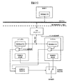
- FIG. 2 shows a system configuration when the ATCU and the monitoring CU are connected by network communication such as CAN.
- the difference from the configuration of FIG. 1 is that the ATCU and the monitoring CU are connected via a network such as CAN communication.
- the ATCU is composed of two CPUs including a main CPU that controls the electric actuator and a sub CPU that monitors the arithmetic function of the main CPU.
- the input to the ATCU includes a rotation pulse signal generated along with the rotation of the primary pulley and the secondary pulley, and other information input via a network such as CAN communication as the target engine speed necessary for calculating the target gear ratio.
- motor position information from the electric actuator that controls the target engine torque and the gear ratio Based on these pieces of information, the main CPU calculates the target drive torque to determine the gear ratio, that is, the control amount of the electric actuator.
- the calculated control amount needs to be converted into a signal for driving the electric actuator, that is, the electric motor, and the main CPU corrects environmental disturbances such as the motor power supply voltage and temperature, and then the control signal is sent to the driver circuit. And the electric actuator is controlled.
- the main CPU performing the control as described above needs to monitor whether each function is operating normally. Therefore, the sub CPU transmits a plurality of function monitoring problems to the main CPU. For the received problem, the main CPU calculates an answer corresponding to the problem using all operators defined in the CPU, and returns the answer to the sub CPU. The sub CPU stores an answer value that cannot be calculated unless the function (operator) that should be supposed is normal, and the main CPU operates normally by checking the answer value with the answer data received from the main CPU. Determine whether or not.
- the monitoring logic mounted on the sub CPU is also mounted on the main CPU so that mutual monitoring is performed between the main CPU and the sub CPU.
- the monitoring electronic control unit (hereinafter referred to as monitoring CU) is configured separately from the ATCU, and is connected to the ATCU via a network such as CAN communication.
- the monitoring CU monitors whether or not the main CPU and sub CPU of the ATCU are operating normally.
- the monitoring method is the same as the mutual monitoring between the main CPU and the sub CPU, and is performed between the main CPU and the monitoring CU and between the sub CPU and the monitoring CU.
- the main CPU, the sub CPU, and the monitoring CU are configured to perform mutual monitoring, and the failure part can be specified.
- the ATCU determines that it is normal, shifts to normal control, and outputs a control signal.
- the CPU receives the monitoring result of the monitoring CU and displays the monitoring result and its own monitoring result. The result is compared, and the result is transmitted to the failure part specifying means.
- the monitoring result of the monitoring CU becomes abnormal although the monitoring results of the main CPU and the sub CPU are both normal, the abnormality information is transmitted to both the main CPU and the sub CPU. Therefore, it is determined that there is a possibility that the monitoring CU has failed, and the main CPU and the sub CPU exclude the monitoring CU from the target of mutual monitoring.
- the failure part specifying means instructs the control signal switching means to switch the control signal based on the monitoring result received by the main CPU and the sub CPU. Specifically, assuming that the main CPU is normal in the initial state, the main CPU calculates a control amount for the electric actuator and outputs a control signal. At this time, the sub CPU and the monitoring CU monitor the function of the main CPU and confirm that there is no abnormality. When it is determined by the sub CPU and the monitoring CU that the main CPU is abnormal, the failure part specifying unit switches the control signal to the control signal switching unit so that the control signal is output from the sub CPU. At this time, the sub CPU takes charge of the main function, and the monitoring CU monitors the sub CPU.
- the monitoring CU can monitor the sub CPU, so there is no need to shift to fail-safe processing, and normal control is performed by the sub CPU. Can be implemented. As a result, the reliability of the system is drastically improved, the system can be applied to a system with a high safety requirement with a simple configuration, and the cost increase can be provided with a minimum.
- FIG. 3 shows a specific example of the monitoring procedure immediately after the ATCU is started.
- each CPU Immediately after the ATCU is activated, each CPU performs a self-diagnosis for the purpose of confirming its own soundness before shifting to normal control (S301).
- the self-diagnosis specifically includes memory diagnosis (ROM / RAM diagnosis), register diagnosis, and the like.
- the main CPU and the monitoring CU can detect an abnormality based on the self-diagnosis result from the sub CPU or the function monitoring result (S303). Thereafter, the sub CPU is excluded from the monitoring mode, and the main CPU is monitored by the monitoring CU (S304).
- the sub CPU transmits a function monitoring signal (hereinafter, an example) to the main CPU (S305).
- the main CPU executes a pre-implemented example calculation program for the example received from the sub CPU, and sends the answer data to the sub CPU (S306).
- the sub CPU determines whether the arithmetic function of the main CPU is normal based on the answer result from the main CPU (S307).
- the sub CPU When it is determined that the main CPU is normal, the sub CPU stores the monitoring result in its own control memory (S308).
- the monitoring result is represented by a three-digit numerical value.
- the first digit is the monitoring result of the main CPU
- the second digit is the monitoring result of the sub CPU
- the third digit is the monitoring result of the monitoring CU
- the monitoring mechanism has a common arrangement, “0” is normal and “1” is abnormal. Therefore, in S308, since the main CPU is normal, the numerical value of the first digit is “0”, and “000” is displayed when three digits are displayed.
- the monitoring CU executes a pre-implemented example calculation program for the example received from the sub CPU, and sends response data to the sub CPU (S310).
- the sub CPU determines whether the arithmetic function of the monitoring CU is normal based on the answer result from the monitoring CU (S311). When it is determined that the monitoring CU is normal, the sub CPU stores the monitoring result in its own control memory (S312). In the present embodiment, since the monitoring result of the monitoring CU is the third digit, “000” is displayed when the main CPU is normal and the monitoring CU is normal and three digits are displayed.
- the sub CPU stores the monitoring result in its own control memory (S313).
- the monitoring result of the monitoring CU is the third digit, “100” is displayed when the main CPU is normal and the monitoring CU is abnormal and the three digits are displayed.
- the sub CPU stores the monitoring result in its own control memory (S314).
- the monitoring result of the main CPU is the third digit, and therefore, when the main CPU displays an error due to an abnormality, “001” is displayed.
- the monitoring CU executes a pre-implemented example calculation program for the example received from the sub CPU, and sends response data to the sub CPU (S316).
- the sub CPU determines whether the arithmetic function of the monitoring CU is normal based on the answer result from the monitoring CU (S317). If it is determined that the monitoring CU is normal, the sub CPU stores the monitoring result in its own control memory (S318). In the present embodiment, since the monitoring result of the monitoring CU is the third digit, “001” is displayed when the main CPU is abnormal and the monitoring CU is normal and three digits are displayed.
- the sub CPU stores the monitoring result in its own control memory (S319).
- the monitoring result of the monitoring CU is the third digit, “101” is displayed when the main CPU is abnormal and the monitoring CU is abnormal and the third digit is displayed.
- the sub CPU can perform function monitoring on the main CPU and the monitoring CU.
- the main CPU and the monitoring CU perform the same processing, mutual monitoring between the three parties can be performed for the first time.
- the main CPU, the sub CPU, and the monitoring CU send the respective monitoring results to the failure part specifying means, and each digit of the monitoring results expressed in three digits is integrated by logical product, any signal that can be represented in FIG.
- the main CPU or the sub CPU fails, the remaining CPU can be controlled normally, the system reliability is dramatically improved, and the system with a high safety requirement has a simple configuration. Applicable.
- the present invention is not limited to such an ATCU monitoring system, and is inexpensive for a system that does not work in the safety direction as a vehicle by stopping the operation of the electronic control unit. It is possible to apply to.
- the present invention even if a plurality of monitoring devices cannot be mounted due to hardware restrictions such as the mounting area of the electronic control device, it is possible to use another electronic control device as a monitoring device if it has some communication means. Therefore, by stopping the operation of the electronic control device, it can be applied to a system that does not work in a safe direction as a vehicle at a low cost.
Abstract
If an electric-actuator-type continuously variable transmission with no oil pump or other oil pressure generators falls into a fail state due to breakdown of a microcontroller of an electronic control device, it is necessary to block a power source to the actuator and to put a motor in a non-operational state, as with a hydraulic actuator type transmission, in order to prevent sudden unintentional acceleration and deceleration. As a result, it becomes impossible for an electric actuator to control the groove width of a pulley, and power (torque) pressing on a V belt is not generated, i.e., the belt falls into a slipping state, making travel impossible. The present invention gives a monitoring function to both a master CPU (for control) and a slave CPU (for monitoring) that constitute an existing electronic control device and causes the CPUs to monitor one other. Moreover, by having another electronic control device also act as a monitoring device via a network, a three-way monitoring configuration is established, making it possible to correctly identify a failure site (CPU).
Description
本発明は、電子制御装置のマイコン故障により、制御対象の機能が失陥することで走行不能になることを防止することを目的とし、マイコン異常と判断された場合でも、電子制御装置として正常動作が要求されるような、安全要求が高いシステムに適用可能なフェールセーフシステム技術に関する。
An object of the present invention is to prevent a malfunction of a control target due to a microcomputer failure in an electronic control device, and to prevent the vehicle from being disabled. Even when it is determined that the microcomputer is abnormal, the electronic control device operates normally. The present invention relates to fail-safe system technology that can be applied to systems with high safety requirements.
現在主流の2個のCPUを用いるマルチCPU構成の電子制御装置については、第2のCPUが異常となったときには第1のCPUにおいてこれを検出し、第2のCPUがリセットされる。そして、第1のCPUから出力される信号によって、リンプホーム可能な制御が実行される。また、第1のCPUに異常が生じたような場合には、これがWDT監視回路において検出されると共に、この第1のCPUにリセットが掛けられ、第2のCPUにおいて異常時の処理が行われて、これまで第1のCPUから出力されていた噴射制御や点火制御の、リンプホームを可能にする異常時処理が第2のCPUにおいて代行されるようになって、第1のCPUからの出力に代わって第2のCPUからの出力による制御が実行される(特許文献1)。
Regarding the electronic control device having a multi-CPU configuration using two CPUs which are currently mainstream, when the second CPU becomes abnormal, the first CPU detects this and the second CPU is reset. Then, control capable of limp home is executed by a signal output from the first CPU. In addition, when an abnormality occurs in the first CPU, this is detected by the WDT monitoring circuit, and the first CPU is reset, and the processing at the time of abnormality is performed in the second CPU. Thus, the abnormal processing that enables limp home of the injection control and ignition control that have been output from the first CPU until now is replaced by the second CPU, and the output from the first CPU Instead of this, control by the output from the second CPU is executed (Patent Document 1).
上記特許文献1に示すようなマルチCPU構成の電子制御装置に対する各CPU間の異常検知手段は、ウォッチドックパルスのみで判断しており、すなわち、ウォッチドックパルスを算出するCPU機能のみで異常を検知しており、CPU機能全体についての診断はできておらず、診断の網羅性の点で、最適な対応策とは言い難い。
The abnormality detection means between the CPUs for the electronic control device having a multi-CPU configuration as shown in Patent Document 1 determines only by the watchdog pulse, that is, detects the abnormality only by the CPU function for calculating the watchdog pulse. However, the entire CPU function has not been diagnosed, and it is difficult to say that it is an optimal countermeasure in terms of comprehensiveness of diagnosis.
そこで本発明は、現在の電子制御装置の構成を大きく変えることなく、少ないシステム構成で電動アクチュエータを備えた車両用自動変速機の電子制御装置内のマイコン故障を検知し、フェールセーフ状態に移行できる監視システム、及び車両用制御装置を提供することを目的とする。
Therefore, the present invention can detect a failure of the microcomputer in the electronic control unit of the automatic transmission for vehicles equipped with the electric actuator with a small system configuration without changing the configuration of the current electronic control unit, and can shift to the fail-safe state. An object is to provide a monitoring system and a vehicle control device.
上記目的を達成するため、本発明は以下の手段を有することを特徴とする。
請求項1、11に係る電動アクチュエータを備えた車両用電子制御装置は、メイン制御部と、メイン制御部を監視するサブ制御部と、監視結果により故障部位を特定する故障部位特定手段と、故障部位の特定結果により制御信号を切り替える制御信号切り替え手段を備える第1の車両用制御装置と、第1の車両用制御装置とは別体で構成される第2の車両用制御装置とを備えた監視システムにおいて、第2の車両用制御装置に設けられた制御部と、第1の車両用制御装置のメイン制御部とサブ制御部との三者間で相互監視を行うことを特徴としている。 In order to achieve the above object, the present invention has the following means.
An electronic control device for a vehicle including an electric actuator according toclaims 1 and 11 includes: a main control unit; a sub-control unit that monitors the main control unit; a failure part specifying unit that specifies a failure part based on a monitoring result; A first vehicle control device including a control signal switching unit that switches a control signal according to a part identification result, and a second vehicle control device configured separately from the first vehicle control device. The monitoring system is characterized in that mutual monitoring is performed between a control unit provided in the second vehicle control device and a main control unit and a sub control unit of the first vehicle control device.
請求項1、11に係る電動アクチュエータを備えた車両用電子制御装置は、メイン制御部と、メイン制御部を監視するサブ制御部と、監視結果により故障部位を特定する故障部位特定手段と、故障部位の特定結果により制御信号を切り替える制御信号切り替え手段を備える第1の車両用制御装置と、第1の車両用制御装置とは別体で構成される第2の車両用制御装置とを備えた監視システムにおいて、第2の車両用制御装置に設けられた制御部と、第1の車両用制御装置のメイン制御部とサブ制御部との三者間で相互監視を行うことを特徴としている。 In order to achieve the above object, the present invention has the following means.
An electronic control device for a vehicle including an electric actuator according to
請求項2、12に係る電動アクチュエータを備えた車両用電子制御装置のサブ制御部は、メイン制御部から出力される演算信号に基づいて該メイン制御部を監視し、該メイン制御部の異常検知時には、故障部位特定手段に異常情報を送信することを特徴としている。
The sub-control unit of the vehicle electronic control device including the electric actuator according to claim 2 or 12 monitors the main control unit based on a calculation signal output from the main control unit, and detects an abnormality in the main control unit. In some cases, abnormal information is transmitted to the failure part specifying means.
請求項3、13に係る電動アクチュエータを備えた車両用制御装置と前記第2の車両用制御装置は、例えばCAN通信などの通信手段により接続されることを特徴としている。
The vehicle control device including the electric actuator according to claims 3 and 13 and the second vehicle control device are connected by communication means such as CAN communication, for example.
請求項4、14に係る電動アクチュエータを備えた車両用制御装置の監視システムは、第2の車両用制御装置とCAN通信などの通信手段により接続され、第2の車両用制御装置に設けられた制御部は、メイン制御部、又はサブ制御部に対し通信手段により診断信号を送信し、メイン制御部、又はサブ制御部からの返信を確認することで、メイン制御部、前記サブ制御部の異常を検知することを特徴としている。
A monitoring system for a vehicle control device including an electric actuator according to claims 4 and 14 is connected to the second vehicle control device by communication means such as CAN communication, and is provided in the second vehicle control device. The control unit transmits a diagnostic signal by communication means to the main control unit or the sub control unit, and confirms a reply from the main control unit or the sub control unit, so that the abnormality of the main control unit and the sub control unit It is characterized by detecting.
請求項5、15に係る電動アクチュエータを備えた車両用制御装置の監視システムは、第2の車両用制御装置に設けられた制御部により、メイン制御部、又はサブ制御部の監視を行い、異常を検知した場合、故障部位特定手段に異常情報を送信すること、を特徴としている。
The monitoring system for a vehicle control device including the electric actuator according to claims 5 and 15 is configured to monitor the main control unit or the sub control unit by a control unit provided in the second vehicle control device. When the error is detected, the abnormality information is transmitted to the failure part specifying means.
請求項6、16に係る電動アクチュエータを備えた車両用制御装置の故障部位特定手段は、メイン制御部と、サブ制御部と、第2の車両制御装置に設けられた制御部からの監視結果を参照し、多数決により故障部位の特定を行い、その判断結果を制御信号切り替え手段に送信することを特徴としている。
The failure part specifying means of the vehicle control device including the electric actuator according to claims 6 and 16 is configured to obtain monitoring results from the main control unit, the sub control unit, and the control unit provided in the second vehicle control device. The failure part is identified by majority decision, and the determination result is transmitted to the control signal switching means.
請求項7、17に係る電動アクチュエータを備えた車両用制御装置の制御信号切り替え手段は、故障部位特定手段からの判断結果に基づき、使用する制御信号をメイン制御部から出力される制御信号か、サブ制御部から出力される制御信号かのどちらかに切り替えることを特徴としている。
The control signal switching means of the vehicle control device provided with the electric actuator according to claim 7 or 17 is a control signal output from the main control unit based on a determination result from the failure part specifying means, It is characterized by switching to one of the control signals output from the sub-control unit.
請求項8、18に係る第2の車両用制御装置に設けられた前記制御部は、メイン制御部、又はサブ制御部の異常が検知された場合に、その後に制御対象に対して制御を行うメイン制御部、又はサブ制御部を監視することを特徴としている。
The control unit provided in the second vehicle control device according to claim 8 or 18 performs control on the control target thereafter when an abnormality of the main control unit or the sub control unit is detected. The main control unit or the sub control unit is monitored.
請求項9、19に係る電動アクチュエータを備えた車両用制御装置のサブ制御部は、メイン制御部の異常を検知した場合に、第2の車両用制御装置に設けられた制御部に対して異常信号を送信し、制御部は異常信号を受信した場合にサブ制御部の監視を行うことを特徴としている。
The sub-control unit of the vehicle control device provided with the electric actuator according to claim 9 or 19 is abnormal with respect to the control unit provided in the second vehicle control device when the abnormality of the main control unit is detected. The control unit transmits a signal, and the control unit monitors the sub-control unit when an abnormal signal is received.
請求項10、20に係る電動アクチュエータを備えた車両用制御装置のメイン制御部は、サブ制御部の監視を行い、メイン制御部及びサブ制御部のうち一方の制御部は他方の制御部の異常を検知した場合に、第2の車両用制御装置に設けられた制御部に対して異常信号を送信し、制御部は異常信号を受信した場合に一方の制御部の監視を行うことを特徴としている。
The main control unit of the vehicle control device including the electric actuator according to claim 10 and 20 monitors the sub-control unit, and one of the main control unit and the sub-control unit is abnormal in the other control unit. When an abnormality signal is detected, an abnormality signal is transmitted to the control unit provided in the second vehicle control device, and the control unit monitors one control unit when the abnormality signal is received. Yes.
本発明の請求項1によれば、一般的な既存の電子制御装置の構成であるマスタCPU(制御用)とスレーブCPU(監視用)から、両CPUとも監視機能を持たせ、且つ相互監視構成とすること。また、ネットワーク経由で他電子制御装置も監視装置と見立てることで、三者間での監視構成となり、故障部位(CPU)が正確に特定できる。
According to the first aspect of the present invention, a master CPU (for control) and a slave CPU (for monitoring), both of which are configurations of a general existing electronic control unit, have both CPUs have a monitoring function, and a mutual monitoring configuration. To do. Further, by assuming that another electronic control device is also a monitoring device via the network, a monitoring configuration between the three parties can be achieved, and the fault site (CPU) can be accurately identified.
本発明のそれ以外の請求項については、以下の実施例において、その作用、効果を詳細に説明する。
The other claims of the present invention will be described in detail in the following examples.
以下、本発明の実施例を、図面を用いて説明する。
Hereinafter, embodiments of the present invention will be described with reference to the drawings.
変速機の多くは油圧にてアクチュエータを制御し、変速動作を実現する。しかし、油圧は応答性が悪く、温度などの環境要因により特性変化が著しい。また、油圧発生器(オイルポンプ)を搭載する必要性があるため、コスト、重量、容積の悪化要因となる。
Most transmissions control actuators with hydraulic pressure to achieve shifting operations. However, hydraulic pressure is poor in response, and characteristic changes are significant due to environmental factors such as temperature. Moreover, since it is necessary to mount a hydraulic pressure generator (oil pump), it becomes a cause of deterioration of cost, weight, and volume.
車両制御装置の電動化の加速により、車両には1台当り多数の電動化装置が搭載されることも考えられる。これらの電子制御装置は、バッテリ等の電源から駆動電力が供給されている。自動変速機の分野についても例外ではなく、油圧アクチュエータとしてリニアソレノイドを使用することもあり、この部分に電動モータを使用した電動アクチュエータを利用することが考えられる。
It is conceivable that a large number of electrification devices are installed in each vehicle due to acceleration of electrification of the vehicle control device. These electronic control devices are supplied with driving power from a power source such as a battery. There is no exception in the field of automatic transmissions, and a linear solenoid may be used as a hydraulic actuator, and it is conceivable to use an electric actuator using an electric motor for this part.
油圧アクチュエータを使用した無段自動変速機では、各プーリに付設された油圧アクチュエータの油圧を制御するノーマルオープン型のリニアソレノイドが備えられている。そして油圧アクチュエータを制御する電子制御装置のマイコン異常などにより、リニアソレノイドに電流を供給することができないフェール状態になった場合には、各油圧アクチュエータに同一の油圧が供給されるように構成される。
¡Continuously variable transmissions using hydraulic actuators are equipped with normally open linear solenoids that control the hydraulic pressure of the hydraulic actuators attached to each pulley. When the failure of the electronic control device that controls the hydraulic actuator is such that a current cannot be supplied to the linear solenoid due to a malfunction of the microcomputer, the same hydraulic pressure is supplied to each hydraulic actuator. .
リニアソレノイドに電流が供給されなくなり、各油圧アクチュエータに同一の油圧が供給された際には、無段変速機の変速比が一定になるようにプーリを設計する。そのため、リニアソレノイドや制御弁がフェールすることにより、油圧が供給されて駆動する油圧供給部を制御することができなっても、最低限、車両を走行させることは可能である。
∙ Design a pulley so that the gear ratio of the continuously variable transmission is constant when no current is supplied to the linear solenoid and the same hydraulic pressure is supplied to each hydraulic actuator. Therefore, even if the linear solenoid or the control valve fails to control the hydraulic pressure supply unit that is driven by the hydraulic pressure, the vehicle can be traveled at a minimum.
また、操舵系に電動アクチュエータを適用した電動パワーステアリングの分野では、マイコン含む電子制御装置の故障が発生した場合、ステアリング機能が失陥し、重大事故に繋がる恐れがある。すなわち、電子制御装置の故障が発生した場合、ステアリング機能の失陥は許容されず、フェールセーフ処理ではなく、通常処理が確実に実行される必要がある。そのため、電動パワーステアリングの電子制御装置を3重系以上の冗長構成とし、常に相互監視することで故障している電子制御装置を確実に検出でき、故障している電子制御装置を監視ループから切り離すことで、ステアリング機能を確保している。
Also, in the field of electric power steering in which an electric actuator is applied to the steering system, if a failure of an electronic control unit including a microcomputer occurs, the steering function may be lost, leading to a serious accident. That is, when a failure of the electronic control device occurs, the failure of the steering function is not allowed, and the normal process needs to be executed reliably, not the fail-safe process. For this reason, the electronic control device for the electric power steering has a redundant configuration with a triple system or more, and by constantly monitoring each other, the failed electronic control device can be reliably detected, and the failed electronic control device is disconnected from the monitoring loop. This ensures the steering function.
しかしながら、オイルポンプなどの油圧発生器を排した電動アクチュエータ方式の無段変速機では、電子制御装置のマイコン故障によりフェール状態になった場合、意図しない急加減速を防止するため、油圧アクチュエータ方式と同様にアクチュエータへの電源を遮断し、モータを非動作状態にする必要がある。その結果、電動アクチュエータによりプーリの溝幅を制御することができなくなるため、Vベルトを押し付ける力(トルク)が発生しない、すなわちベルトすべり状態に陥り、走行不能となる。
However, in an electric actuator type continuously variable transmission that excludes an oil pressure generator such as an oil pump, in order to prevent unintended sudden acceleration / deceleration when a failure occurs due to a microcomputer failure in the electronic control unit, Similarly, it is necessary to shut off the power supply to the actuator and put the motor in a non-operating state. As a result, since it becomes impossible to control the groove width of the pulley by the electric actuator, a force (torque) for pressing the V-belt is not generated, that is, the belt slips and cannot run.
また、電子制御装置を3重系以上の冗長構成とした相互監視構成をとった場合、電子制御装置の実装面積が通常の3倍となるため、多数の電子制御部品が実装されている昨今の車両では問題となることが必至である。また、コスト面でも同様で、電動ステアリング装置のように、機能が失陥すると重大な事故に繋がる可能性があるデバイスに関しては、電子制御装置の冗長化も一つの手段となるが、変速機の分野では、電子制御装置の機能が失陥しても重大な事故には繋がる可能性はないため、費用対効果を考慮すると、最適な対応策とは言い難い。
In addition, when a mutual monitoring configuration is adopted in which the electronic control device is a redundant configuration of a triple system or more, the mounting area of the electronic control device is three times the normal, so that a large number of electronic control components are mounted in recent times. It will inevitably be a problem in vehicles. In addition, the cost is the same. For devices that can lead to a serious accident if the function is lost, such as an electric steering device, redundancy of the electronic control unit is one means. In the field, even if the function of the electronic control device fails, there is no possibility that it will lead to a serious accident. Therefore, it is difficult to say that it is an optimal countermeasure in consideration of cost effectiveness.
そこで以下の本発明の実施例においては、現在の電子制御装置の構成を大きく変えることなく、最小のシステム構成で電動アクチュエータを備えた車両用自動変速機(特に自動無段変速機)の電子制御装置内のマイコン故障を確実に検知し、確実にフェールセーフ状態に移行できる監視システムについて説明する。
Therefore, in the following embodiments of the present invention, electronic control of an automatic transmission for a vehicle (particularly, an automatic continuously variable transmission) having an electric actuator with a minimum system configuration without greatly changing the configuration of the current electronic control unit. A monitoring system capable of reliably detecting a microcomputer failure in the apparatus and reliably shifting to a fail-safe state will be described.
図1に、電動アクチュエータを備えた自動無段変速機を対象とした、請求項1の電子制御装置(以下、ATCU)における監視システムの一例を示す。
FIG. 1 shows an example of a monitoring system in an electronic control unit (hereinafter referred to as ATCU) according to claim 1 for an automatic continuously variable transmission equipped with an electric actuator.
ATCUは、電動アクチュエータを制御するメインCPUと、メインCPUの演算機能を監視するサブCPUとを備えた、2CPUで構成される。ATCUに対する入力としては、プライマリプーリとセカンダリプーリの回転に伴い発生される回転パルス信号、その他、CAN通信などのネットワーク経由で入力される情報としては、目標変速比の算出に必要な目標エンジン回転数と目標エンジントルク、変速比を制御する電動アクチュエータからのモータ位置情報が存在する。これらの情報を基にメインCPUは、目標駆動トルクを算出することで、変速比、すなわち電動アクチュエータの制御量が決定される。算出された制御量は、電動アクチュエータ、すなわち電動モータを駆動するための信号に変換する必要があり、メインCPUでは、モータ電源電圧や温度などの環境外乱補正を行ったうえで制御信号がドライバ回路へ出力され、電動アクチュエータが制御される。
The ATCU is composed of two CPUs including a main CPU that controls the electric actuator and a sub CPU that monitors the arithmetic function of the main CPU. The input to the ATCU includes a rotation pulse signal generated along with the rotation of the primary pulley and the secondary pulley, and other information input via a network such as CAN communication as the target engine speed necessary for calculating the target gear ratio. And motor position information from the electric actuator that controls the target engine torque and the gear ratio. Based on these pieces of information, the main CPU calculates the target drive torque to determine the gear ratio, that is, the control amount of the electric actuator. The calculated control amount needs to be converted into a signal for driving the electric actuator, that is, the electric motor, and the main CPU corrects environmental disturbances such as the motor power supply voltage and temperature, and then the control signal is sent to the driver circuit. And the electric actuator is controlled.
上記の様な制御を行っているメインCPUは、それぞれの機能が正常に動作しているか否かを監視する必要がある。そこでサブCPUは、メインCPUに対し、複数の機能監視用の問題を送信する。メインCPUでは、受信した問題に対し、該CPUで定義されているすべての演算子を使用して問題に対応した回答を算出し、サブCPUに返信する。サブCPUは、本来あるべき機能(演算子)が正常でないと算出できない回答値を記憶しており、その値をメインCPUから受信した回答データと照合することで、メインCPUが正常に動作しているか否かを判断する。
The main CPU performing the control as described above needs to monitor whether each function is operating normally. Therefore, the sub CPU transmits a plurality of function monitoring problems to the main CPU. For the received problem, the main CPU calculates an answer corresponding to the problem using all operators defined in the CPU, and returns the answer to the sub CPU. The sub CPU stores an answer value that cannot be calculated unless the function (operator) that should be supposed is normal, and the main CPU operates normally by checking the answer value with the answer data received from the main CPU. Determine whether or not.
サブCPUがメインCPUの監視を行う一方で、監視側のサブCPUについても健全性を保証する必要がある。そこで、サブCPUに実装されている監視ロジックをメインCPUにも実装することで、メインCPUとサブCPU間で相互監視を行う構成とする。
While the sub CPU monitors the main CPU, it is necessary to guarantee the soundness of the sub CPU on the monitoring side. Therefore, the monitoring logic mounted on the sub CPU is also mounted on the main CPU so that mutual monitoring is performed between the main CPU and the sub CPU.
監視用電子制御装置(以下、監視CU)は、ATCUとは別体で構成し、ATCUとは通信線で接続されている。監視CUは、ATCUのメインCPU、およびサブCPUが正常に動作しているか否かを監視している。監視方法としては、上記メインCPUとサブCPU間の相互監視と同一の構成であり、メインCPUと監視CU間、サブCPUと監視CU間で実施する。
The monitoring electronic control unit (hereinafter referred to as monitoring CU) is configured separately from the ATCU, and is connected to the ATCU via a communication line. The monitoring CU monitors whether or not the main CPU and sub CPU of the ATCU are operating normally. The monitoring method is the same as the mutual monitoring between the main CPU and the sub CPU, and is performed between the main CPU and the monitoring CU and between the sub CPU and the monitoring CU.
以上により、メインCPUとサブCPUと監視CUの三者で相互監視の構成となり、故障部位の特定が可能となる。
As described above, the main CPU, the sub CPU, and the monitoring CU are configured to perform mutual monitoring, and the failure part can be specified.
その後、監視結果を故障部位特定手段に集約し、故障部位の特定を行う。最初に、メインCPUとサブCPUの監視結果を照合する。このとき、どちらも異常を検知していない場合は、ATCUは正常と判断し、通常制御に移行し制御信号を出力する。対して、メインCPUとサブCPUの監視結果が異なる、すなわち、どちらか一方が異常と判断された結果が監視結果を故障部位特定手段に送信された場合には、監視CUの監視結果を参照し、監視CUでの監視結果と同じ判断をしたCPUを正常とする。一方で、故障部位特定手段に送信された監視結果において、メインCPUとサブCPUの監視結果が、どちらも正常であるにも関わらず、監視CUでの監視結果が異常となった場合には、監視CUが故障している可能性があるため、メインCPUとサブCPUは監視CUを相互監視の対象から除外する。
After that, the monitoring results are collected in the failure part specifying means, and the failure part is specified. First, the monitoring results of the main CPU and the sub CPU are collated. At this time, if neither has detected an abnormality, the ATCU determines that it is normal, shifts to normal control, and outputs a control signal. On the other hand, when the monitoring results of the main CPU and the sub CPU are different, that is, when one of the results determined to be abnormal is transmitted to the failure location specifying means, the monitoring result of the monitoring CU is referred to. The CPU that makes the same judgment as the monitoring result in the monitoring CU is assumed to be normal. On the other hand, in the monitoring result transmitted to the failure part specifying means, when the monitoring result of the monitoring CU becomes abnormal although the monitoring results of the main CPU and the sub CPU are both normal, Since there is a possibility that the monitoring CU is out of order, the main CPU and the sub CPU exclude the monitoring CU from mutual monitoring.
故障部位特定手段は、メインCPUとサブCPU、監視CUから受信した監視結果を基に、制御信号切り替え手段に制御信号の切り替え指示を行う。具体的には、初期状態はメインCPUが正常と仮定すると、メインCPUで電動アクチュエータに対する制御量を算出し、制御信号を出力する。このとき、サブCPUと監視CUはメインCPUの機能監視を行い、異常がないことを確認する。サブCPUと監視CUにより、メインCPUが異常だと判断された場合、故障部位特定手段は制御信号切り替え手段に対し、サブCPUから制御信号が出力されるように制御信号を切り替える。この際、サブCPUが主機能を受け持つことになり、監視CUがサブCPUの監視を行うことになる。
The failure part specifying means instructs the control signal switching means to switch the control signal based on the monitoring result received from the main CPU, the sub CPU, and the monitoring CU. Specifically, assuming that the main CPU is normal in the initial state, the main CPU calculates a control amount for the electric actuator and outputs a control signal. At this time, the sub CPU and the monitoring CU monitor the function of the main CPU and confirm that there is no abnormality. When it is determined by the sub CPU and the monitoring CU that the main CPU is abnormal, the failure part specifying unit switches the control signal to the control signal switching unit so that the control signal is output from the sub CPU. At this time, the sub CPU takes charge of the main function, and the monitoring CU monitors the sub CPU.
以上の構成により、故障部位が好適に特定できることに加え、メインCPUが故障しても、監視CUがサブCPUを監視できるため、特にフェールセーフ処理に移行する必要が無く、サブCPUにて通常制御の実施が可能となる。その結果、システムの信頼性が飛躍的に向上し、安全要求の高いシステムにも単純な構成で適用可能であり、コストアップも最小で提供可能である。
With the above configuration, in addition to being able to suitably identify the failed part, even if the main CPU fails, the monitoring CU can monitor the sub CPU, so there is no need to shift to fail-safe processing, and normal control is performed by the sub CPU. Can be implemented. As a result, the reliability of the system is drastically improved, the system can be applied to a system with a high safety requirement with a simple configuration, and the cost increase can be provided with a minimum.
また、電子制御装置に実装される2つのCPUを、制御機能と相互監視機能について同一の機能を持たせることで、どちらか一方がCPU異常になった場合でも、制御切り替え手段により制御CPUを切り替え、正常なCPUでの通常制御が実行可能となる。
In addition, by providing the two CPUs mounted on the electronic control unit with the same function for the control function and the mutual monitoring function, even when one of the CPUs becomes abnormal, the control switching means switches the control CPU. Normal control with a normal CPU can be executed.
したがって、例えば電動アクチュエータによって変速制御される自動無段変速機において、同一電子制御装置内で制御CPUを監視CPUが監視するといった、既存の電子制御装置の構成では、制御CPU異常時は、安全性確保の観点から、監視CPUが電動アクチュエータの電源を遮断するしかフェールセーフ処理の方法が無いが、本実施例の構成であれば、他電子制御装置からの監視を含め三者間での監視構成の為、故障部位(CPU)の正確な特定に加え、制御切り替え手段による正常な制御CPUへの切り替えをすることで、通常制御が実行可能となる。
Therefore, for example, in an automatic continuously variable transmission whose speed is controlled by an electric actuator, in a configuration of an existing electronic control device in which the control CPU monitors the control CPU in the same electronic control device, safety is achieved when the control CPU is abnormal. From the standpoint of securing, there is only a fail-safe processing method by the monitoring CPU shutting off the power supply of the electric actuator, but in the case of the configuration of the present embodiment, the monitoring configuration between the three parties including monitoring from other electronic control devices For this reason, normal control can be executed by switching to a normal control CPU by the control switching means in addition to accurately specifying the failed part (CPU).
その結果、既存の電子制御装置の監視構成では、CPU異常により電動アクチュエータへの電源を遮断するフェールセーフ処理を実行することで、油圧アクチュエータ式の自動無段変速機のように変速比を固定することができず、走行不能となってしまうが、本発明では、電子制御装置内のどちらか一方のCPUが異常となっても、もう一方の正常なCPUと他電子制御装置との相互監視により、安全性が保障されているため、電動アクチュエータを確実にフェールセーフ制御、さらには通常制御で動作させることも可能となるため、安全要求の高いシステムに適用することができる。
As a result, in the monitoring configuration of the existing electronic control device, the gear ratio is fixed like a hydraulic actuator type automatic continuously variable transmission by executing fail-safe processing that cuts off the power supply to the electric actuator due to CPU abnormality. In the present invention, even if one of the CPUs in the electronic control device becomes abnormal, in the present invention, mutual monitoring between the other normal CPU and the other electronic control device Since the safety is ensured, the electric actuator can be reliably operated by fail-safe control, and further by normal control, so that it can be applied to a system requiring high safety.
また、安全要求の高いシステムでは必然的に電子制御装置の多重化の手法がとられるが、本実施例では多重化の必要が無く、従来の監視用CPUから制御用CPUへの性能向上と、他電子制御装置への監視制御を組み込むのみであり、システムコストの低減に効果が期待できる。
Also, in a system with high safety requirements, the method of multiplexing the electronic control device is inevitably taken, but in this embodiment, there is no need for multiplexing, and the performance improvement from the conventional monitoring CPU to the control CPU, Only monitoring control to other electronic control devices is incorporated, and an effect can be expected to reduce the system cost.
図2に、ATCUと監視CUをCANなどのネットワーク通信で繋いだ場合のシステム構成を示す。図1の構成との違いは、ATCUと監視CUが、CAN通信などのネットワーク経由で接続されている点である。
FIG. 2 shows a system configuration when the ATCU and the monitoring CU are connected by network communication such as CAN. The difference from the configuration of FIG. 1 is that the ATCU and the monitoring CU are connected via a network such as CAN communication.
ATCUは、電動アクチュエータを制御するメインCPUと、メインCPUの演算機能を監視するサブCPUとを備えた、2CPUで構成される。ATCUに対する入力としては、プライマリプーリとセカンダリプーリの回転に伴い発生される回転パルス信号、その他、CAN通信などのネットワーク経由で入力される情報としては、目標変速比の算出に必要な目標エンジン回転数と目標エンジントルク、変速比を制御する電動アクチュエータからのモータ位置情報が存在する。これらの情報を基にメインCPUは、目標駆動トルクを算出することで、変速比、すなわち電動アクチュエータの制御量が決定される。算出された制御量は、電動アクチュエータ、すなわち電動モータを駆動するための信号に変換する必要があり、メインCPUでは、モータ電源電圧や温度などの環境外乱補正を行ったうえで制御信号がドライバ回路へ出力され、電動アクチュエータが制御される。
The ATCU is composed of two CPUs including a main CPU that controls the electric actuator and a sub CPU that monitors the arithmetic function of the main CPU. The input to the ATCU includes a rotation pulse signal generated along with the rotation of the primary pulley and the secondary pulley, and other information input via a network such as CAN communication as the target engine speed necessary for calculating the target gear ratio. And motor position information from the electric actuator that controls the target engine torque and the gear ratio. Based on these pieces of information, the main CPU calculates the target drive torque to determine the gear ratio, that is, the control amount of the electric actuator. The calculated control amount needs to be converted into a signal for driving the electric actuator, that is, the electric motor, and the main CPU corrects environmental disturbances such as the motor power supply voltage and temperature, and then the control signal is sent to the driver circuit. And the electric actuator is controlled.
上記の様な制御を行っているメインCPUは、それぞれの機能が正常に動作しているか否かを監視する必要がある。そこでサブCPUは、メインCPUに対し、複数の機能監視用の問題を送信する。メインCPUでは、受信した問題に対し、該CPUで定義されているすべての演算子を使用して問題に対応した回答を算出し、サブCPUに返信する。サブCPUは、本来あるべき機能(演算子)が正常でないと算出できない回答値を記憶しており、その値をメインCPUから受信した回答データと照合することで、メインCPUが正常に動作しているか否かを判断する。
The main CPU performing the control as described above needs to monitor whether each function is operating normally. Therefore, the sub CPU transmits a plurality of function monitoring problems to the main CPU. For the received problem, the main CPU calculates an answer corresponding to the problem using all operators defined in the CPU, and returns the answer to the sub CPU. The sub CPU stores an answer value that cannot be calculated unless the function (operator) that should be supposed is normal, and the main CPU operates normally by checking the answer value with the answer data received from the main CPU. Determine whether or not.
サブCPUがメインCPUの監視を行う一方で、監視側のサブCPUについても健全性を保証する必要がある。そこで、サブCPUに実装されている監視ロジックをメインCPUにも実装することで、メインCPUとサブCPU間で相互監視を行う構成とする。
While the sub CPU monitors the main CPU, it is necessary to guarantee the soundness of the sub CPU on the monitoring side. Therefore, the monitoring logic mounted on the sub CPU is also mounted on the main CPU so that mutual monitoring is performed between the main CPU and the sub CPU.
監視用電子制御装置(以下、監視CU)は、ATCUとは別体で構成し、ATCUとはCAN通信などのネットワーク経由で接続されている。監視CUは、ATCUのメインCPU、およびサブCPUが正常に動作しているか否かを監視している。監視方法としては、上記メインCPUとサブCPU間の相互監視と同一の構成であり、メインCPUと監視CU間、サブCPUと監視CU間で実施する。
The monitoring electronic control unit (hereinafter referred to as monitoring CU) is configured separately from the ATCU, and is connected to the ATCU via a network such as CAN communication. The monitoring CU monitors whether or not the main CPU and sub CPU of the ATCU are operating normally. The monitoring method is the same as the mutual monitoring between the main CPU and the sub CPU, and is performed between the main CPU and the monitoring CU and between the sub CPU and the monitoring CU.
以上により、メインCPUとサブCPUと監視CUの三者で相互監視の構成となり、故障部位の特定が可能となる。
As described above, the main CPU, the sub CPU, and the monitoring CU are configured to perform mutual monitoring, and the failure part can be specified.
最初に、メインCPUとサブCPUの監視結果を照合する。このとき、どちらも異常を検知していない場合は、ATCUは正常と判断し、通常制御に移行し制御信号を出力する。対して、メインCPUとサブCPUの監視結果が異なる、すなわち、どちらか一方が異常と判断された場合には、該CPUは監視CUの監視結果を受信し、その監視結果と自身の監視結果を比較し、結果を故障部位特定手段へ送信する。一方で、メインCPUとサブCPUの監視結果が、どちらも正常であるにも関わらず、監視CUでの監視結果が異常となった場合には、メインCPUとサブCPUの双方に異常情報が送信されるため、監視CUが故障している可能性があると判断し、メインCPUとサブCPUは監視CUを相互監視の対象から除外する。
First, check the monitoring results of the main CPU and sub CPU. At this time, if neither has detected an abnormality, the ATCU determines that it is normal, shifts to normal control, and outputs a control signal. On the other hand, when the monitoring results of the main CPU and the sub CPU are different, that is, when one of them is determined to be abnormal, the CPU receives the monitoring result of the monitoring CU and displays the monitoring result and its own monitoring result. The result is compared, and the result is transmitted to the failure part specifying means. On the other hand, when the monitoring result of the monitoring CU becomes abnormal although the monitoring results of the main CPU and the sub CPU are both normal, the abnormality information is transmitted to both the main CPU and the sub CPU. Therefore, it is determined that there is a possibility that the monitoring CU has failed, and the main CPU and the sub CPU exclude the monitoring CU from the target of mutual monitoring.
故障部位特定手段は、メインCPUとサブCPU受信した監視結果を基に、制御信号切り替え手段に制御信号の切り替え指示を行う。具体的には、初期状態はメインCPUが正常と仮定すると、メインCPUで電動アクチュエータに対する制御量を算出し、制御信号を出力する。このとき、サブCPUと監視CUはメインCPUの機能監視を行い、異常がないことを確認する。サブCPUと監視CUにより、メインCPUが異常だと判断された場合、故障部位特定手段は制御信号切り替え手段に対し、サブCPUから制御信号が出力されるように制御信号を切り替える。この際、サブCPUが主機能を受け持つことになり、監視CUがサブCPUの監視を行うことになる。
The failure part specifying means instructs the control signal switching means to switch the control signal based on the monitoring result received by the main CPU and the sub CPU. Specifically, assuming that the main CPU is normal in the initial state, the main CPU calculates a control amount for the electric actuator and outputs a control signal. At this time, the sub CPU and the monitoring CU monitor the function of the main CPU and confirm that there is no abnormality. When it is determined by the sub CPU and the monitoring CU that the main CPU is abnormal, the failure part specifying unit switches the control signal to the control signal switching unit so that the control signal is output from the sub CPU. At this time, the sub CPU takes charge of the main function, and the monitoring CU monitors the sub CPU.
以上の構成により、故障部位が好適に特定できることに加え、メインCPUが故障しても、監視CUがサブCPUを監視できるため、特にフェールセーフ処理に移行する必要が無く、サブCPUにて通常制御の実施が可能となる。その結果、システムの信頼性が飛躍的に向上し、安全要求の高いシステムにも単純な構成で適用可能であり、コストアップも最小で提供可能である。
With the above configuration, in addition to being able to suitably identify the failed part, even if the main CPU fails, the monitoring CU can monitor the sub CPU, so there is no need to shift to fail-safe processing, and normal control is performed by the sub CPU. Can be implemented. As a result, the reliability of the system is drastically improved, the system can be applied to a system with a high safety requirement with a simple configuration, and the cost increase can be provided with a minimum.
図3に、ATCUが起動直後の監視手順の具体例を示す。
FIG. 3 shows a specific example of the monitoring procedure immediately after the ATCU is started.
ATCUが起動した直後、各CPUは通常制御へ移行する前に自己の健全性を確認することを目的に、自己診断を実施する(S301)。ここで自己診断とは、具体的にはメモリ診断(ROM/RAM診断)やレジスタ診断などが挙げられる。
Immediately after the ATCU is activated, each CPU performs a self-diagnosis for the purpose of confirming its own soundness before shifting to normal control (S301). Here, the self-diagnosis specifically includes memory diagnosis (ROM / RAM diagnosis), register diagnosis, and the like.
サブCPUの自己診断が異常の場合(S302)、他CPUの監視に対する信頼性は無くなるため、メインCPUの監視は実施するべきではない。このとき、メインCPU、及び監視CUはサブCPUからの自己診断結果、または機能監視結果により異常を検知することが可能である(S303)。その後、サブCPUを監視形態から除外し、監視CUによりメインCPUを監視する形態をとる(S304)。
If the sub-CPU self-diagnosis is abnormal (S302), the reliability of the monitoring of other CPUs is lost, so the monitoring of the main CPU should not be performed. At this time, the main CPU and the monitoring CU can detect an abnormality based on the self-diagnosis result from the sub CPU or the function monitoring result (S303). Thereafter, the sub CPU is excluded from the monitoring mode, and the main CPU is monitored by the monitoring CU (S304).
サブCPUの自己診断結果が正常の場合、サブCPUはメインCPUへ機能監視のための信号(以下、例題)を送信する(S305)。メインCPUでは、サブCPUから受け取った例題に対し、予め実装してある例題演算プログラムを実行し、回答データがサブCPUに送付される(S306)。サブCPUでは、メインCPUからの回答結果を基に、メインCPUの演算機能が正常か否か判断する(S307)。
When the self-diagnosis result of the sub CPU is normal, the sub CPU transmits a function monitoring signal (hereinafter, an example) to the main CPU (S305). The main CPU executes a pre-implemented example calculation program for the example received from the sub CPU, and sends the answer data to the sub CPU (S306). The sub CPU determines whether the arithmetic function of the main CPU is normal based on the answer result from the main CPU (S307).
メインCPUが正常と判断された場合、サブCPUはその監視結果を自身の制御メモリに記憶する(S308)。本実施例では、監視結果を3桁の数値で表し、1桁目の数値はメインCPUの監視結果、2桁目はサブCPUの監視結果、3桁目は監視CUの監視結果と、3つの監視機構で共通の配置とし、“0”が正常、“1”が異常としている。よって、S308では、メインCPUが正常であるため、1桁目の数値は“0”となり、3桁表示すると“000”となる。
When it is determined that the main CPU is normal, the sub CPU stores the monitoring result in its own control memory (S308). In this embodiment, the monitoring result is represented by a three-digit numerical value. The first digit is the monitoring result of the main CPU, the second digit is the monitoring result of the sub CPU, the third digit is the monitoring result of the monitoring CU, and The monitoring mechanism has a common arrangement, “0” is normal and “1” is abnormal. Therefore, in S308, since the main CPU is normal, the numerical value of the first digit is “0”, and “000” is displayed when three digits are displayed.
次に、三者での相互監視の観点から、監視CUの機能監視が必要であるため、監視CUへ例題を送信する(S309)。監視CUでは、サブCPUから受け取った例題に対し、予め実装してある例題演算プログラムを実行し、回答データがサブCPUに送付される(S310)。サブCPUでは、監視CUからの回答結果を基に、監視CUの演算機能が正常か否か判断する(S311)。監視CUが正常と判断された場合、サブCPUはその監視結果を自身の制御メモリに記憶する(S312)。本実施例では、監視CUの監視結果は3桁目であるため、メインCPUが正常、且つ、監視CUが正常により、3桁表示すると“000”となる。
Next, from the viewpoint of mutual monitoring by the three parties, monitoring of the function of the monitoring CU is necessary, so an example is transmitted to the monitoring CU (S309). The monitoring CU executes a pre-implemented example calculation program for the example received from the sub CPU, and sends response data to the sub CPU (S310). The sub CPU determines whether the arithmetic function of the monitoring CU is normal based on the answer result from the monitoring CU (S311). When it is determined that the monitoring CU is normal, the sub CPU stores the monitoring result in its own control memory (S312). In the present embodiment, since the monitoring result of the monitoring CU is the third digit, “000” is displayed when the main CPU is normal and the monitoring CU is normal and three digits are displayed.
対して、S311で監視CUが異常と判断された場合、サブCPUはその監視結果を自身の制御メモリに記憶する(S313)。本実施例では、監視CUの監視結果は3桁目であるため、メインCPUが正常、且つ、監視CUが異常により、3桁表示すると“100”となる。
On the other hand, if the monitoring CU is determined to be abnormal in S311, the sub CPU stores the monitoring result in its own control memory (S313). In this embodiment, since the monitoring result of the monitoring CU is the third digit, “100” is displayed when the main CPU is normal and the monitoring CU is abnormal and the three digits are displayed.
対して、S307でメインCPUが異常と判断された場合、サブCPUはその監視結果を自身の制御メモリに記憶する(S314)。本実施例では、メインCPUの監視結果は3桁目であるため、メインCPUが異常により、3桁表示すると“001”となる。
On the other hand, when the main CPU is determined to be abnormal in S307, the sub CPU stores the monitoring result in its own control memory (S314). In the present embodiment, the monitoring result of the main CPU is the third digit, and therefore, when the main CPU displays an error due to an abnormality, “001” is displayed.
次に、三者での相互監視の観点から、監視CUの機能監視が必要であるため、監視CUへ例題を送信する(S315)。監視CUでは、サブCPUから受け取った例題に対し、予め実装してある例題演算プログラムを実行し、回答データがサブCPUに送付される(S316)。サブCPUでは、監視CUからの回答結果を基に、監視CUの演算機能が正常か否か判断する(S317)。監視CUが正常と判断された場合、サブCPUはその監視結果を自身の制御メモリに記憶する(S318)。本実施例では、監視CUの監視結果は3桁目であるため、メインCPUが異常、且つ、監視CUが正常により、3桁表示すると“001”となる。
Next, from the viewpoint of mutual monitoring by the three parties, the function monitoring of the monitoring CU is necessary, so an example is transmitted to the monitoring CU (S315). The monitoring CU executes a pre-implemented example calculation program for the example received from the sub CPU, and sends response data to the sub CPU (S316). The sub CPU determines whether the arithmetic function of the monitoring CU is normal based on the answer result from the monitoring CU (S317). If it is determined that the monitoring CU is normal, the sub CPU stores the monitoring result in its own control memory (S318). In the present embodiment, since the monitoring result of the monitoring CU is the third digit, “001” is displayed when the main CPU is abnormal and the monitoring CU is normal and three digits are displayed.
対して、S317で監視CUが異常と判断された場合、サブCPUはその監視結果を自身の制御メモリに記憶する(S319)。本実施例では、監視CUの監視結果は3桁目であるため、メインCPUが異常、且つ、監視CUが異常により、3桁表示すると“101”となる。
On the other hand, if the monitoring CU is determined to be abnormal in S317, the sub CPU stores the monitoring result in its own control memory (S319). In the present embodiment, since the monitoring result of the monitoring CU is the third digit, “101” is displayed when the main CPU is abnormal and the monitoring CU is abnormal and the third digit is displayed.
以上の処理で、サブCPUが、メインCPUと監視CUに対して機能監視を実施可能であるが、同一処理をメインCPUと監視CUが行うことで、初めて三者間の相互監視が可能となる。メインCPU、サブCPU、監視CUがそれぞれの監視結果を故障部位特定手段に送信し、3桁で表現される監視結果の各桁に対し、論理積により統合すると図5に表せる何れかの信号になり、故障部位の特定に加えて電動アクチュエータに出力する制御信号の切り替えも可能となる。その結果、メインCPUとサブCPUのどちらかが故障しても、残ったCPUで正常に制御可能であり、システムの信頼性が飛躍的に向上し、安全要求の高いシステムにも単純な構成で適用できる。
With the above processing, the sub CPU can perform function monitoring on the main CPU and the monitoring CU. However, when the main CPU and the monitoring CU perform the same processing, mutual monitoring between the three parties can be performed for the first time. . When the main CPU, the sub CPU, and the monitoring CU send the respective monitoring results to the failure part specifying means, and each digit of the monitoring results expressed in three digits is integrated by logical product, any signal that can be represented in FIG. Thus, it is possible to switch the control signal output to the electric actuator in addition to specifying the failed part. As a result, even if either the main CPU or the sub CPU fails, the remaining CPU can be controlled normally, the system reliability is dramatically improved, and the system with a high safety requirement has a simple configuration. Applicable.
以上、本発明の構成について説明したが、本発明はこうしたATCUの監視システムに限定されるものではなく、電子制御装置の動作を停止させることにより、車両として安全方向に働かないシステムに対し、安価に応用することが可能である。
Although the configuration of the present invention has been described above, the present invention is not limited to such an ATCU monitoring system, and is inexpensive for a system that does not work in the safety direction as a vehicle by stopping the operation of the electronic control unit. It is possible to apply to.
本発明によれば、電子制御装置の実装面積などハードウェアの制約により監視装置を複数実装できない場合でも、何かしらの通信手段を持っていれば、他の電子制御装置を監視装置にすることが可能であり、電子制御装置の動作を停止させることにより、車両として安全方向に働かないシステムに対し、安価に応用することが可能である。
According to the present invention, even if a plurality of monitoring devices cannot be mounted due to hardware restrictions such as the mounting area of the electronic control device, it is possible to use another electronic control device as a monitoring device if it has some communication means. Therefore, by stopping the operation of the electronic control device, it can be applied to a system that does not work in a safe direction as a vehicle at a low cost.
S301 初回起動時のサブCPU自己診断処理
S302 サブCPUの自己診断結果の判断
S303 メインCPU、監視CUによるサブCPU異常検知処理
S304 メインCPUの監視をサブCPUから監視CUに切り替える処理
S305 メインCPUへの例題送信処理
S306 メインCPUからの回答受信処理
S307 メインCPUの機能監視結果の判断
S308 メインCPUの機能正常判断時の記憶処理
S309 監視CUへの例題送信処理
S310 監視CUからの回答受信処理
S311 監視CUの機能監視結果の判断
S312 監視CUの機能正常判断時の記憶処理
S313 監視CUの機能異常判断時の記憶処理
S314 メインCPUの機能異常判断時の記憶処理
S315 監視CUへの例題送信処理
S316 監視CUからの回答受信処理
S317 監視CUの機能監視結果の判断
S318 監視CUの機能正常判断時の記憶処理
S319 監視CUの機能異常判断時の記憶処理 S301 Sub CPU self-diagnosis process at the time of first startup S302 Sub CPU self-diagnosis result determination S303 Sub CPU abnormality detection process by main CPU and monitoring CU S304 Process for switching main CPU from sub CPU to monitoring CU S305 Example transmission process S306 Response reception process from main CPU S307 Main CPU function monitoring result determination S308 Main CPU function normality determination storage process S309 Example transmission process to monitoring CU S310 Response reception process from monitoring CU S311 Monitoring CU Function monitoring result determination S312 Storage process at the time of monitoring CU function normality determination S313 Storage process at the time of monitoring CU function error determination S314 Storage process at the time of main CPU function error determination S315 Example transmission process to the monitoring CU S316 Monitoring CU Answer from Processing S317 Judgment of monitoring result of function of monitoring CU S318 Storage processing when functioning of monitoring CU function is normal S319 Storage processing when judging function abnormality of monitoring CU
Claims (20)
- メイン制御部と、該メイン制御部を監視するサブ制御部と、監視結果により故障部位を特定する故障部位特定手段と、故障部位の特定結果により制御信号を切り替える制御信号切り替え手段と、を有する第1の車両用制御装置と、
前記第1の車両用制御装置とは別体で構成される第2の車両用制御装置と、を備えた監視システムにおいて、
前記第2の車両用制御装置に設けられた制御部と、前記第1の車両用制御装置の前記メイン制御部と、前記サブ制御部と、で相互監視を行うこと、を特徴とする監視システム。 A main control unit; a sub-control unit that monitors the main control unit; a faulty part specifying unit that specifies a faulty part based on a monitoring result; and a control signal switching unit that switches a control signal based on the faulty part specifying result. 1 vehicle control device;
In a monitoring system comprising: a second vehicle control device configured separately from the first vehicle control device;
A monitoring system comprising: a control unit provided in the second vehicle control device; the main control unit of the first vehicle control device; and the sub-control unit. . - 請求項1に記載の監視システムにおいて、
前記サブ制御部は、前記メイン制御部から出力される演算信号に基づいて該メイン制御部を監視し、該メイン制御部の異常検知時には、前記故障部位特定手段に異常情報を送信すること、を特徴とする監視システム。 The monitoring system according to claim 1,
The sub-control unit monitors the main control unit based on a calculation signal output from the main control unit, and transmits abnormality information to the faulty part specifying unit when abnormality is detected in the main control unit; A characteristic surveillance system. - 請求項1に記載の監視システムにおいて、
前記第1の車両用制御装置と前記第2の車両用制御装置とは、通信手段により接続されること、を特徴とする監視システム。 The monitoring system according to claim 1,
The first vehicle control device and the second vehicle control device are connected by communication means. - 請求項1に記載の監視システムにおいて、
前記第1の車両用制御装置と前記第2の車両用制御装置とは、通信手段により接続され、
前記第2の車両用制御装置に設けられた前記制御部は、前記メイン制御部、又は前記サブ制御部に対し前記通信手段により信号を送信し、前記メイン制御部、又は前記サブ制御部からの返信を確認することで、前記メイン制御部、又は前記サブ制御部の異常を検知すること、を特徴とする監視システム。 The monitoring system according to claim 1,
The first vehicle control device and the second vehicle control device are connected by communication means,
The control unit provided in the second vehicle control device transmits a signal to the main control unit or the sub control unit by the communication unit, and from the main control unit or the sub control unit. A monitoring system characterized by detecting an abnormality in the main control unit or the sub control unit by confirming a reply. - 請求項1に記載の監視システムにおいて、
前記第2の車両用制御装置に設けられた制御部により、前記メイン制御部、又は前記サブ制御部の監視を行い、異常を検知した場合、前記故障部位特定手段に異常情報を送信すること、を特徴とする監視システム。 The monitoring system according to claim 1,
By monitoring the main control unit or the sub-control unit by the control unit provided in the second vehicle control device and detecting an abnormality, transmitting abnormality information to the failure part specifying unit; A monitoring system characterized by - 請求項1に記載の監視システムにおいて、
前記故障部位特定手段は、前記メイン制御部と、前記サブ制御部と、前記第2の車両制御装置に設けられた制御部からの監視結果を参照し、多数決により故障部位の特定を行い、その判断結果を制御信号切り替え手段に送信すること、を特徴とする監視システム。 The monitoring system according to claim 1,
The failure part specifying means refers to monitoring results from the main control part, the sub control part, and a control part provided in the second vehicle control device, specifies a failure part by majority decision, A monitoring system characterized by transmitting a determination result to a control signal switching means. - 請求項1に記載の監視システムにおいて、
前記制御信号切り替え手段は、前記故障部位特定手段からの判断結果に基づき、使用する制御信号を、前記メイン制御部から出力される制御信号か、前記サブ制御部から出力される制御信号か、のどちらかに切り替えること、を特徴とする監視システム。 The monitoring system according to claim 1,
The control signal switching means, based on the determination result from the failure part specifying means, whether the control signal to be used is a control signal output from the main control section or a control signal output from the sub-control section. A monitoring system characterized by switching to either. - 請求項1に記載の監視システムにおいて、
前記第2の車両用制御装置に設けられた前記制御部は、前記メイン制御部、又は前記サブ制御部の異常が検知された場合に、その後に制御対象に対して制御を行う前記メイン制御部、又は前記サブ制御部を監視することを特徴とする監視システム。 The monitoring system according to claim 1,
The control unit provided in the second vehicle control device is configured to control the control target after an abnormality of the main control unit or the sub control unit is detected. Or a monitoring system for monitoring the sub-control unit. - 請求項1に記載の監視システムにおいて、
前記サブ制御部は前記メイン制御部の異常を検知した場合に、前記第2の車両用制御装置に設けられた前記制御部に対して異常信号を送信し、該制御部は前記異常信号を受信した場合に前記サブ制御部の監視を行うことを特徴とする監視システム。 The monitoring system according to claim 1,
When the sub control unit detects an abnormality in the main control unit, the sub control unit transmits an abnormality signal to the control unit provided in the second vehicle control device, and the control unit receives the abnormality signal. And a monitoring system for monitoring the sub-control unit. - 請求項1に記載の監視システムにおいて、
前記メイン制御部は前記サブ制御部の監視を行い、前記メイン制御部及び前記サブ制御部のうち一方の制御部は他方の制御部の異常を検知した場合に、前記第2の車両用制御装置に設けられた前記制御部に対して異常信号を送信し、該制御部は前記異常信号を受信した場合に前記一方の制御部の監視を行うことを特徴とする監視システム。 The monitoring system according to claim 1,
The main control unit monitors the sub control unit, and when one of the main control unit and the sub control unit detects an abnormality of the other control unit, the second control device for a vehicle. A monitoring system, wherein an abnormal signal is transmitted to the control unit provided in the control unit, and the control unit monitors the one control unit when receiving the abnormal signal. - メイン制御部と、該メイン制御部を監視するサブ制御部と、監視結果により故障部位を特定する故障部位特定手段と、故障部位の特定結果により制御信号を切り替える制御信号切り替え手段と、を備えた車両用制御装置において、
当該車両用制御装置とは別体で構成される制御装置に設けられた制御部と、前記メイン制御部と、前記サブ制御部と、で相互監視が行われること、を特徴とする車両用制御装置。 A main control unit; a sub-control unit that monitors the main control unit; a faulty part specifying unit that specifies a faulty part based on a monitoring result; and a control signal switching unit that switches a control signal based on the faulty part specifying result. In a vehicle control device,
Vehicle control characterized in that mutual monitoring is performed by a control unit provided in a control device configured separately from the vehicle control device, the main control unit, and the sub-control unit. apparatus. - 請求項11に記載の車両用制御装置において、
前記サブ制御部は、前記メイン制御部から出力される演算信号に基づいて該メイン制御部を監視し、該メイン制御部の異常検知時には、前記故障部位特定手段に異常情報を送信すること、を特徴とする車両用制御装置。 The vehicle control device according to claim 11,
The sub-control unit monitors the main control unit based on a calculation signal output from the main control unit, and transmits abnormality information to the faulty part specifying unit when abnormality is detected in the main control unit; A vehicle control device. - 請求項11に記載の車両用制御装置において、
当該車両用制御装置と別体で構成される前記制御装置とは、通信手段により接続されること、を特徴とする車両用制御装置。 The vehicle control device according to claim 11,
The vehicle control device, wherein the control device configured separately from the vehicle control device is connected by communication means. - 請求項11に記載の車両用制御装置において、
当該車両用制御装置と別体で構成される前記制御装置とは、通信手段により接続され、
前記制御装置に設けられた前記制御部は、前記メイン制御部、又は前記サブ制御部に対し前記通信手段により信号を送信し、前記メイン制御部、又は前記サブ制御部からの返信を確認することで、前記メイン制御部、又は前記サブ制御部の異常を検知すること、を特徴とする車両用制御装置。 The vehicle control device according to claim 11,
The control device configured separately from the vehicle control device is connected by communication means,
The control unit provided in the control device transmits a signal to the main control unit or the sub control unit by the communication unit, and confirms a reply from the main control unit or the sub control unit. Then, a vehicle control device characterized by detecting an abnormality in the main control unit or the sub control unit. - 請求項11に記載の車両用制御装置において、
当該車両用制御装置とは別体で構成される制御装置に設けられた前記制御部により、前記メイン制御部、又は前記サブ制御部の監視を行い、異常を検知した場合、前記故障部位特定手段に異常情報を送信すること、を特徴とする車両用制御装置。 The vehicle control device according to claim 11,
When the control unit provided in a control device configured separately from the vehicle control device monitors the main control unit or the sub control unit and detects an abnormality, the failure part specifying means An abnormality information is transmitted to the vehicle control device. - 請求項11に記載の車両用制御装置において、
前記故障部位特定手段は、前記メイン制御部と、前記サブ制御部と、当該車両用制御装置とは別体で構成される制御装置に設けられた前記制御部からの監視結果を参照し、多数決により故障部位の特定を行い、その判断結果を制御信号切り替え手段に送信すること、を特徴とする車両用制御装置。 The vehicle control device according to claim 11,
The failure part specifying means refers to a monitoring result from the control unit provided in a control device configured separately from the main control unit, the sub control unit, and the vehicle control device, and determines a majority. A vehicle control device characterized by identifying a faulty part and transmitting the determination result to a control signal switching means. - 請求項11に記載の車両用制御装置において、
前記制御信号切り替え手段は、前記故障部位特定手段からの判断結果に基づき、使用する制御信号を、前記メイン制御部から出力される制御信号か、前記サブ制御部から出力される制御信号か、のどちらかに切り替えること、を特徴とする車両用制御装置。 The vehicle control device according to claim 11,
The control signal switching means, based on the determination result from the failure part specifying means, whether the control signal to be used is a control signal output from the main control section or a control signal output from the sub-control section. A vehicle control device characterized by switching to either one. - 請求項11に記載の車両用制御装置において、
前記制御装置に設けられた前記制御部は、前記メイン制御部、又は前記サブ制御部の異常が検知された場合に、その後に制御対象に対して制御を行う前記メイン制御部、又は前記サブ制御部を監視すること、を特徴とする車両用制御装置。 The vehicle control device according to claim 11,
The control unit provided in the control device is configured to control the control target after the main control unit or the sub control when an abnormality of the main control unit or the sub control unit is detected. The vehicle control device characterized by monitoring a part. - 請求項11に記載の車両用制御装置において、
前記サブ制御部は前記メイン制御部の異常を検知した場合に、前記制御装置に設けられた前記制御部に対して異常信号を送信し、該制御部は前記異常信号を受信した場合に前記サブ制御部の監視を行うこと、を特徴とする車両用制御装置。 The vehicle control device according to claim 11,
When the sub control unit detects an abnormality in the main control unit, the sub control unit transmits an abnormality signal to the control unit provided in the control device, and when the control unit receives the abnormality signal, the sub control unit transmits the abnormality signal. A vehicle control device characterized by monitoring a control unit. - 請求項11に記載の車両用制御装置において、
前記メイン制御部は前記サブ制御部の監視を行い、前記メイン制御部及び前記サブ制御部のうち一方の制御部は他方の制御部の異常を検知した場合に、前記制御装置に設けられた前記制御部に対して異常信号を送信し、該制御部は前記異常信号を受信した場合に前記一方の制御部の監視を行うこと、を特徴とする車両用制御装置。 The vehicle control device according to claim 11,
The main control unit monitors the sub control unit, and when one of the main control unit and the sub control unit detects an abnormality of the other control unit, the main control unit is provided in the control device. A vehicle control device, wherein an abnormality signal is transmitted to a control unit, and the control unit monitors the one control unit when the abnormality signal is received.
Priority Applications (4)
| Application Number | Priority Date | Filing Date | Title |
|---|---|---|---|
| CN201680055528.6A CN108025687B (en) | 2015-09-29 | 2016-08-02 | Monitoring system and vehicle control device |
| JP2017542976A JP6777641B2 (en) | 2015-09-29 | 2016-08-02 | Surveillance system and vehicle control device |
| EP16850865.3A EP3357760A4 (en) | 2015-09-29 | 2016-08-02 | Monitoring system and vehicle control device |
| US15/741,623 US10808836B2 (en) | 2015-09-29 | 2016-08-02 | Monitoring system and vehicle control device |
Applications Claiming Priority (2)
| Application Number | Priority Date | Filing Date | Title |
|---|---|---|---|
| JP2015-190626 | 2015-09-29 | ||
| JP2015190626 | 2015-09-29 |
Publications (1)
| Publication Number | Publication Date |
|---|---|
| WO2017056688A1 true WO2017056688A1 (en) | 2017-04-06 |
Family
ID=58423446
Family Applications (1)
| Application Number | Title | Priority Date | Filing Date |
|---|---|---|---|
| PCT/JP2016/072582 WO2017056688A1 (en) | 2015-09-29 | 2016-08-02 | Monitoring system and vehicle control device |
Country Status (5)
| Country | Link |
|---|---|
| US (1) | US10808836B2 (en) |
| EP (1) | EP3357760A4 (en) |
| JP (1) | JP6777641B2 (en) |
| CN (1) | CN108025687B (en) |
| WO (1) | WO2017056688A1 (en) |
Cited By (6)
| Publication number | Priority date | Publication date | Assignee | Title |
|---|---|---|---|---|
| WO2019058607A1 (en) * | 2017-09-22 | 2019-03-28 | 日立オートモティブシステムズ株式会社 | On-vehicle electronic control device and abnormal state processing method |
| JP2019071572A (en) * | 2017-10-10 | 2019-05-09 | ローベルト ボッシュ ゲゼルシャフト ミット ベシュレンクテル ハフツング | Control apparatus and control method |
| JP6732143B1 (en) * | 2019-07-31 | 2020-07-29 | 三菱電機株式会社 | Vehicle control device |
| JP2021064855A (en) * | 2019-10-11 | 2021-04-22 | 株式会社デンソー | Electronic control device |
| KR20210050575A (en) * | 2018-09-18 | 2021-05-07 | 크노르-브렘제 시스테메 퓌어 누츠파조이게 게엠베하 | Control architecture for vehicles |
| JP2021181944A (en) * | 2020-05-20 | 2021-11-25 | トヨタ自動車株式会社 | On-vehicle component abnormal portion specifying method, on-vehicle component abnormal portion specifying system, on-vehicle component abnormal portion specifying device, on-vehicle component abnormal portion notification control unit, and control unit for vehicle |
Families Citing this family (4)
| Publication number | Priority date | Publication date | Assignee | Title |
|---|---|---|---|---|
| JP6614078B2 (en) * | 2016-09-09 | 2019-12-04 | 株式会社デンソー | Shift range control device |
| CN111114241B (en) * | 2018-10-31 | 2022-06-21 | 浙江三花智能控制股份有限公司 | Control system and control method |
| CN113335298A (en) * | 2021-05-28 | 2021-09-03 | 广汽丰田汽车有限公司 | CPU fault processing method, vehicle and readable storage medium |
| DE102021206379A1 (en) * | 2021-06-22 | 2022-12-22 | Continental Autonomous Mobility Germany GmbH | Control device and assistance system for a vehicle |
Citations (4)
| Publication number | Priority date | Publication date | Assignee | Title |
|---|---|---|---|---|
| JPS60151705A (en) * | 1984-01-18 | 1985-08-09 | Hitachi Ltd | Multiplex controller |
| JP2000225935A (en) * | 1999-02-03 | 2000-08-15 | Toyota Motor Corp | Electrically controlled brake system |
| JP2004189163A (en) * | 2002-12-13 | 2004-07-08 | Honda Motor Co Ltd | Steering device for vehicle |
| JP2007126127A (en) * | 2005-10-03 | 2007-05-24 | Hitachi Ltd | Vehicle control system |
Family Cites Families (22)
| Publication number | Priority date | Publication date | Assignee | Title |
|---|---|---|---|---|
| JPS56135250A (en) * | 1980-03-24 | 1981-10-22 | Nissan Motor Co Ltd | Output device of microcomputer |
| JPS6347549A (en) * | 1986-08-11 | 1988-02-29 | Aisin Warner Ltd | Automatic transmission provided with fail-safe function |
| EP0398381B1 (en) * | 1989-05-19 | 1993-12-15 | Nissan Motor Co., Ltd. | Apparatus for detecting failure occurring in control system for driving load |
| JPH07293320A (en) | 1994-04-21 | 1995-11-07 | Nippondenso Co Ltd | Electronic controller |
| JP3362537B2 (en) * | 1994-12-27 | 2003-01-07 | 日産自動車株式会社 | Fail-safe control of drive motor for electric vehicles |
| JP2000029734A (en) | 1998-07-13 | 2000-01-28 | Nissan Motor Co Ltd | Cpu abnormality monitoring system |
| JP2003333675A (en) * | 2002-05-14 | 2003-11-21 | Hitachi Ltd | Communication system control apparatus and abnormality monitoring method therefor |
| DE10243713B4 (en) | 2002-09-20 | 2006-10-05 | Daimlerchrysler Ag | Redundant control unit arrangement |
| DE10302456A1 (en) | 2003-01-23 | 2004-07-29 | Robert Bosch Gmbh | Computer device for safety-critical applications has at least a processor unit and memory unit with both units situated on the same chip surface |
| JP4373238B2 (en) * | 2003-08-19 | 2009-11-25 | 株式会社日立製作所 | Power steering device |
| CN100492223C (en) * | 2007-03-30 | 2009-05-27 | 哈尔滨工程大学 | Switch circuit for engine redundant electrically-controlled system |
| JP2009122831A (en) | 2007-11-13 | 2009-06-04 | Mitsubishi Electric Corp | Electronic control device |
| JP4907576B2 (en) * | 2008-03-18 | 2012-03-28 | ジヤトコ株式会社 | Abnormality monitoring device for arithmetic processing unit |
| JP5234599B2 (en) * | 2008-05-23 | 2013-07-10 | 日野自動車株式会社 | Power supply system fault diagnosis system for vehicle driver unit |
| JP5143690B2 (en) * | 2008-09-30 | 2013-02-13 | アイシン・エィ・ダブリュ株式会社 | Hydraulic control device for automatic transmission |
| JP5158208B2 (en) * | 2008-12-19 | 2013-03-06 | アイシン・エィ・ダブリュ株式会社 | Shift-by-wire device and transmission device having the same |
| JP5573227B2 (en) * | 2010-03-01 | 2014-08-20 | 株式会社デンソー | Starter control device |
| JP5684514B2 (en) * | 2010-08-19 | 2015-03-11 | 株式会社東芝 | Redundant control system and calculation data transmission method thereof |
| JP5126393B2 (en) * | 2011-06-29 | 2013-01-23 | 日本精工株式会社 | In-vehicle electronic control unit |
| JP6179098B2 (en) * | 2012-12-25 | 2017-08-16 | 株式会社ジェイテクト | Electric power steering device |
| CN204086849U (en) * | 2014-04-29 | 2015-01-07 | 北京龙鼎源科技有限公司 | Programmable Logic Controller redundancy control system |
| JP6364486B2 (en) * | 2014-06-18 | 2018-07-25 | 日立オートモティブシステムズ株式会社 | In-vehicle control device or in-vehicle control system |
-
2016
- 2016-08-02 EP EP16850865.3A patent/EP3357760A4/en active Pending
- 2016-08-02 JP JP2017542976A patent/JP6777641B2/en active Active
- 2016-08-02 CN CN201680055528.6A patent/CN108025687B/en active Active
- 2016-08-02 US US15/741,623 patent/US10808836B2/en active Active
- 2016-08-02 WO PCT/JP2016/072582 patent/WO2017056688A1/en active Application Filing
Patent Citations (4)
| Publication number | Priority date | Publication date | Assignee | Title |
|---|---|---|---|---|
| JPS60151705A (en) * | 1984-01-18 | 1985-08-09 | Hitachi Ltd | Multiplex controller |
| JP2000225935A (en) * | 1999-02-03 | 2000-08-15 | Toyota Motor Corp | Electrically controlled brake system |
| JP2004189163A (en) * | 2002-12-13 | 2004-07-08 | Honda Motor Co Ltd | Steering device for vehicle |
| JP2007126127A (en) * | 2005-10-03 | 2007-05-24 | Hitachi Ltd | Vehicle control system |
Non-Patent Citations (1)
| Title |
|---|
| See also references of EP3357760A4 * |
Cited By (13)
| Publication number | Priority date | Publication date | Assignee | Title |
|---|---|---|---|---|
| US10964135B2 (en) | 2017-09-22 | 2021-03-30 | Hitachi Automotive Systems, Ltd. | In-vehicle electronic control unit and method for abnormality response processing thereof |
| JP2019057187A (en) * | 2017-09-22 | 2019-04-11 | 日立オートモティブシステムズ株式会社 | On-vehicle electronic control unit and abnormality time treatment method for the same |
| CN111164577A (en) * | 2017-09-22 | 2020-05-15 | 日立汽车系统株式会社 | Vehicle-mounted electronic control device and abnormal time processing method thereof |
| WO2019058607A1 (en) * | 2017-09-22 | 2019-03-28 | 日立オートモティブシステムズ株式会社 | On-vehicle electronic control device and abnormal state processing method |
| JP2019071572A (en) * | 2017-10-10 | 2019-05-09 | ローベルト ボッシュ ゲゼルシャフト ミット ベシュレンクテル ハフツング | Control apparatus and control method |
| KR20210050575A (en) * | 2018-09-18 | 2021-05-07 | 크노르-브렘제 시스테메 퓌어 누츠파조이게 게엠베하 | Control architecture for vehicles |
| KR102488152B1 (en) | 2018-09-18 | 2023-01-12 | 크노르-브렘제 시스테메 퓌어 누츠파조이게 게엠베하 | Control architecture for vehicles |
| JP6732143B1 (en) * | 2019-07-31 | 2020-07-29 | 三菱電機株式会社 | Vehicle control device |
| WO2021019715A1 (en) * | 2019-07-31 | 2021-02-04 | 三菱電機株式会社 | Vehicle control device |
| JP2021064855A (en) * | 2019-10-11 | 2021-04-22 | 株式会社デンソー | Electronic control device |
| JP7205439B2 (en) | 2019-10-11 | 2023-01-17 | 株式会社デンソー | electronic controller |
| JP2021181944A (en) * | 2020-05-20 | 2021-11-25 | トヨタ自動車株式会社 | On-vehicle component abnormal portion specifying method, on-vehicle component abnormal portion specifying system, on-vehicle component abnormal portion specifying device, on-vehicle component abnormal portion notification control unit, and control unit for vehicle |
| JP7327273B2 (en) | 2020-05-20 | 2023-08-16 | トヨタ自動車株式会社 | Method for Identifying Abnormal Location of Automotive Part, System for Identifying Abnormal Location of Automotive Part, Device for Identifying Abnormal Location of Automotive Part, Abnormal Location Notification Control Device for Automotive Part, and Control Device for Vehicle |
Also Published As
| Publication number | Publication date |
|---|---|
| JPWO2017056688A1 (en) | 2018-05-24 |
| US10808836B2 (en) | 2020-10-20 |
| EP3357760A4 (en) | 2019-06-19 |
| JP6777641B2 (en) | 2020-10-28 |
| CN108025687B (en) | 2021-12-21 |
| US20180202544A1 (en) | 2018-07-19 |
| CN108025687A (en) | 2018-05-11 |
| EP3357760A1 (en) | 2018-08-08 |
Similar Documents
| Publication | Publication Date | Title |
|---|---|---|
| WO2017056688A1 (en) | Monitoring system and vehicle control device | |
| JP6714611B2 (en) | Method and apparatus for providing redundancy in a vehicle electronic control system | |
| US7789345B2 (en) | Actuator control apparatus | |
| WO2015194407A1 (en) | Vehicle-mounted control device or vehicle-mounted control system | |
| US8340793B2 (en) | Architecture using integrated backup control and protection hardware | |
| JPH0545460B2 (en) | ||
| US20100018384A1 (en) | Drive system and method of monitoring a hydrostatic drive | |
| EP1363174B1 (en) | Communication control system and method for supervising a failure | |
| US20130158844A1 (en) | Method for operating a control unit | |
| JP6334436B2 (en) | Mutual monitoring module for vehicles | |
| JP2006036187A (en) | Control device for automobile and method for monitoring abnormality thereof | |
| CN113014150B (en) | Motor control system, method for operating a motor control system and aircraft | |
| JP7014140B2 (en) | Electromagnetic brake control device and control device | |
| CN108369879B (en) | Method and device for monitoring the function of redundant interconnection contacts | |
| KR101448013B1 (en) | Fault-tolerant apparatus and method in multi-computer for Unmanned Aerial Vehicle | |
| KR20030055866A (en) | A difficulty diagnosing and putting apparatus in eps system | |
| CN114630783A (en) | Evaluation device for fault-tolerant evaluation of sensor signals for a motor controller of a motor vehicle steering system, and motor vehicle steering system | |
| JP2010211760A (en) | Control system of construction machine | |
| EP3315825B1 (en) | Control device for vehicle transmission | |
| US11760203B2 (en) | On-vehicle control device | |
| KR20140070020A (en) | Control device safety system for construction equipment having dual control system | |
| JP6716429B2 (en) | Electronic control device and diagnostic method thereof | |
| JPH11230328A (en) | Emergency operation device for automatic transmission | |
| JP2018080710A (en) | Transmission control device | |
| JPH02310137A (en) | Communication system of electronic equipment for automobile |
Legal Events
| Date | Code | Title | Description |
|---|---|---|---|
| 121 | Ep: the epo has been informed by wipo that ep was designated in this application |
Ref document number: 16850865 Country of ref document: EP Kind code of ref document: A1 |
|
| ENP | Entry into the national phase |
Ref document number: 2017542976 Country of ref document: JP Kind code of ref document: A |
|
| WWE | Wipo information: entry into national phase |
Ref document number: 15741623 Country of ref document: US |
|
| NENP | Non-entry into the national phase |
Ref country code: DE |