EP0398381B1 - Apparatus for detecting failure occurring in control system for driving load - Google Patents
Apparatus for detecting failure occurring in control system for driving load Download PDFInfo
- Publication number
- EP0398381B1 EP0398381B1 EP90109588A EP90109588A EP0398381B1 EP 0398381 B1 EP0398381 B1 EP 0398381B1 EP 90109588 A EP90109588 A EP 90109588A EP 90109588 A EP90109588 A EP 90109588A EP 0398381 B1 EP0398381 B1 EP 0398381B1
- Authority
- EP
- European Patent Office
- Prior art keywords
- signal
- driving
- dither
- failure
- control load
- Prior art date
- Legal status (The legal status is an assumption and is not a legal conclusion. Google has not performed a legal analysis and makes no representation as to the accuracy of the status listed.)
- Expired - Lifetime
Links
Images


Classifications
-
- B—PERFORMING OPERATIONS; TRANSPORTING
- B62—LAND VEHICLES FOR TRAVELLING OTHERWISE THAN ON RAILS
- B62D—MOTOR VEHICLES; TRAILERS
- B62D7/00—Steering linkage; Stub axles or their mountings
- B62D7/06—Steering linkage; Stub axles or their mountings for individually-pivoted wheels, e.g. on king-pins
- B62D7/14—Steering linkage; Stub axles or their mountings for individually-pivoted wheels, e.g. on king-pins the pivotal axes being situated in more than one plane transverse to the longitudinal centre line of the vehicle, e.g. all-wheel steering
- B62D7/148—Steering linkage; Stub axles or their mountings for individually-pivoted wheels, e.g. on king-pins the pivotal axes being situated in more than one plane transverse to the longitudinal centre line of the vehicle, e.g. all-wheel steering provided with safety devices
-
- B—PERFORMING OPERATIONS; TRANSPORTING
- B60—VEHICLES IN GENERAL
- B60G—VEHICLE SUSPENSION ARRANGEMENTS
- B60G17/00—Resilient suspensions having means for adjusting the spring or vibration-damper characteristics, for regulating the distance between a supporting surface and a sprung part of vehicle or for locking suspension during use to meet varying vehicular or surface conditions, e.g. due to speed or load
- B60G17/015—Resilient suspensions having means for adjusting the spring or vibration-damper characteristics, for regulating the distance between a supporting surface and a sprung part of vehicle or for locking suspension during use to meet varying vehicular or surface conditions, e.g. due to speed or load the regulating means comprising electric or electronic elements
- B60G17/016—Resilient suspensions having means for adjusting the spring or vibration-damper characteristics, for regulating the distance between a supporting surface and a sprung part of vehicle or for locking suspension during use to meet varying vehicular or surface conditions, e.g. due to speed or load the regulating means comprising electric or electronic elements characterised by their responsiveness, when the vehicle is travelling, to specific motion, a specific condition, or driver input
- B60G17/0162—Resilient suspensions having means for adjusting the spring or vibration-damper characteristics, for regulating the distance between a supporting surface and a sprung part of vehicle or for locking suspension during use to meet varying vehicular or surface conditions, e.g. due to speed or load the regulating means comprising electric or electronic elements characterised by their responsiveness, when the vehicle is travelling, to specific motion, a specific condition, or driver input mainly during a motion involving steering operation, e.g. cornering, overtaking
- B60G17/0163—Resilient suspensions having means for adjusting the spring or vibration-damper characteristics, for regulating the distance between a supporting surface and a sprung part of vehicle or for locking suspension during use to meet varying vehicular or surface conditions, e.g. due to speed or load the regulating means comprising electric or electronic elements characterised by their responsiveness, when the vehicle is travelling, to specific motion, a specific condition, or driver input mainly during a motion involving steering operation, e.g. cornering, overtaking the control involving steering geometry, e.g. four-wheel steering
-
- B—PERFORMING OPERATIONS; TRANSPORTING
- B60—VEHICLES IN GENERAL
- B60G—VEHICLE SUSPENSION ARRANGEMENTS
- B60G17/00—Resilient suspensions having means for adjusting the spring or vibration-damper characteristics, for regulating the distance between a supporting surface and a sprung part of vehicle or for locking suspension during use to meet varying vehicular or surface conditions, e.g. due to speed or load
- B60G17/015—Resilient suspensions having means for adjusting the spring or vibration-damper characteristics, for regulating the distance between a supporting surface and a sprung part of vehicle or for locking suspension during use to meet varying vehicular or surface conditions, e.g. due to speed or load the regulating means comprising electric or electronic elements
- B60G17/018—Resilient suspensions having means for adjusting the spring or vibration-damper characteristics, for regulating the distance between a supporting surface and a sprung part of vehicle or for locking suspension during use to meet varying vehicular or surface conditions, e.g. due to speed or load the regulating means comprising electric or electronic elements characterised by the use of a specific signal treatment or control method
- B60G17/0185—Resilient suspensions having means for adjusting the spring or vibration-damper characteristics, for regulating the distance between a supporting surface and a sprung part of vehicle or for locking suspension during use to meet varying vehicular or surface conditions, e.g. due to speed or load the regulating means comprising electric or electronic elements characterised by the use of a specific signal treatment or control method for failure detection
-
- B—PERFORMING OPERATIONS; TRANSPORTING
- B60—VEHICLES IN GENERAL
- B60G—VEHICLE SUSPENSION ARRANGEMENTS
- B60G2400/00—Indexing codes relating to detected, measured or calculated conditions or factors
- B60G2400/20—Speed
- B60G2400/204—Vehicle speed
-
- B—PERFORMING OPERATIONS; TRANSPORTING
- B60—VEHICLES IN GENERAL
- B60G—VEHICLE SUSPENSION ARRANGEMENTS
- B60G2400/00—Indexing codes relating to detected, measured or calculated conditions or factors
- B60G2400/30—Propulsion unit conditions
-
- B—PERFORMING OPERATIONS; TRANSPORTING
- B60—VEHICLES IN GENERAL
- B60G—VEHICLE SUSPENSION ARRANGEMENTS
- B60G2400/00—Indexing codes relating to detected, measured or calculated conditions or factors
- B60G2400/40—Steering conditions
- B60G2400/41—Steering angle
-
- B—PERFORMING OPERATIONS; TRANSPORTING
- B60—VEHICLES IN GENERAL
- B60G—VEHICLE SUSPENSION ARRANGEMENTS
- B60G2600/00—Indexing codes relating to particular elements, systems or processes used on suspension systems or suspension control systems
- B60G2600/08—Failure or malfunction detecting means
-
- B—PERFORMING OPERATIONS; TRANSPORTING
- B60—VEHICLES IN GENERAL
- B60G—VEHICLE SUSPENSION ARRANGEMENTS
- B60G2600/00—Indexing codes relating to particular elements, systems or processes used on suspension systems or suspension control systems
- B60G2600/22—Magnetic elements
- B60G2600/26—Electromagnets; Solenoids
Definitions
- the present invention relates generally to a system for detecting failure occurring in a control system operating an inductance load. More particularly, the invention relates to a failure detecting system applicable to various control systems such as for a four wheel steering system or an active suspension control system.
- a Japanese Patent First Publication No. 2-18169 discloses a rear wheel steering control system for a vehicle which includes an apparatus for detecting failure occurring in a load driving system.
- This control system is operable to determine a rear wheel steering target angle based on a front wheel steered angle and vehicle speed so as to obtain an optimal vehicular dynamic characteristic when turning to steer the rear wheels at a phase angle opposite the direction of front wheels or at the same phase as the front wheels by means of a hydraulic actuator which improves traveling stability and steering responsiveness.
- control system includes a microcomputer for controlling hydraulic pressure to be applied to the hydraulic actuator and a driving circuit for the latter.
- the microcomputer calculates a necessary rear wheel steering angle.
- the driving circuit provides current corresponding to the calculated rear wheel steering angle to an electromagnetic valve to apply pressurized hydraulic fluid to the actuator for controlling rear wheel steering.
- a clock signal generator For monitoring the microcomputer, a clock signal generator is provided which generates clock signals to a signal line in which operation of the microcomputer can be monitored.
- a watchdog timer monitors the clock signals in a signal current output through the signal line to detect failure such as overload of the microcomputer.
- the system For monitoring the driving circuit, the system monitors the current value of a linear driving current flowing in the wire harness to detect failure.
- the time during which the failure can be dectected is limited to a specific period. Additionally, since the system requires two separate failure detecting units for each of the microcomputer and the driving circuit, conventional systems such as described become complex and expensive.
- a Japanese Patent First Publication No. 64-63463 which is owned by the assignee of this application, discloses another failure detecting system which includes a clock signal generator interposed between a microcomputer and a driving circuit for a rear wheel steering power cylinder to apply a current with a dither signal to the latter.
- the system monitors the dither signal in the current output from the driving circuit to detect failure in a system controlling a driven load.
- This system comprises the features of the preamble of claim 1.
- the system detects the failure after the signal is output from the microcomputer, it cannot detect a failure in said microcomputer.
- the failure detection system of the invention is defined by the features of claim 1. This system does not monitor only a dither signal for failure detection but it monitors additionally the variation in the level of the driving signal to deactivate the failure detecting operation in response to a variation out of a preselected range. Thereby, erroneous failure indications during transition periods can be omitted.
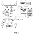
- Fig. 1 is a schematic view which shows a four wheel steering control system including a system for detecting failure therein according to the present invention.
- Fig. 2 is a block diagram which shows a rear wheel steering control unit according to the invention.
- Figs. 3 and 4 are flowcharts which show a sequence or logical steps carried out by a rear wheel steering control unit.
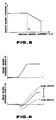
- Fig. 5 is a graph which shows a dither signal/driving signal current relationship showing solenoid characteristics.
- Fig. 6 is a graph which shows a time-chart example of rear wheel steering control.
- Fig. 7 is a block diagram which shows a load model including a digital filter.
- Fig. 8 is a block diagram which shows a driving circuit for solenoids.
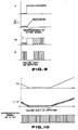
- Fig. 9 is a time-chart which shows signal characteristics in a transient period where signals input to a solenoid driving circuit are changed suddenly.
- Fig. 10 is a time-chart which shows a relationship between a rear wheel steering target angle, a solenoid driving signal with a dither signal, and a differentiated signal of the solenoid driving signal with the dither signal.
- a failure detecting system according to the present invention is shown which is incorporated in a four wheel steering (4WS) vehicle including a rear wheel steering control system.
- Front wheels 1L (left) and 1R (right) are driven by a steering gear 4 according to rotation of a steering wheel 3.
- Rear wheels 2L and 2R are driven by a rear wheel steering actuator or a power cylinder 5.
- the rear wheel steering power cylinder 5 is a spring-centered type hydraulic cylinder in which two separate chambers 5L and 5R are formed each connected to an electromagnetic proportional pressure control valve 6. Supplying pressurized hydraulic fluid to the chamber 5R causes the rear wheels 2L and 2R to steer respectively to the right at an angle proportional to the pressure of the applied hydraulic fluid, while supplying pressurized hydraulic fluid to the chamber 5L causes the rear wheels to steer to the left respectively at an angle proportional to the pressure of the applied hydraulic fluid.
- the electromagnetic proportional pressure control valve 6 is operable to control hydraulic pressure to be applied to the cylinder chambers 5L and 5R and includes a bridge circuit provided with four variable throttle valves 6a, 6b, 6c, and 6d. This bridge circuit communicates with a reservoir tank 8, a hydraulic pump 7, and the power cylinder 5 via fluid lines 12, 13, 9-1, 9-2, 10-1, and 10-2.
- the pressure control valve 6 further includes solenoides 6R and 6L which open the variable throttle valves 6a, 6b and 6c, 6d respectively in an OFF state to provide no pressure to the cylinder chambers 5L and 5R, while in an ON state they close the variable throttle valves 6a and 6b or 6c and 6d to a degree corresponding to the magnitude of currents I L * or I R * , which are provided with dither signals as will be described hereinafter, applied thereto to provide hydraulic pressure corresponding to the above signal magnitudes to the cylinder chambers 5L or 5R, steering the rear wheels at an angle corresponding to the hydraulic pressure.
- a normally closed type cutoff valve 20 which includes a solenoid 20a is interposed between the pressure control valve 6 and the rear wheel power cylinder 5 through lines 9-1, 9-2, and 10-1, 10-2.
- the cutoff valve 20 is operable to shut out hydraulic fluid flowing between the lines 9-1 and 9-2 and between lines 10-1 and 10-2 when a solenoid driving current I F is not present at the solenoid 20a due to an OFF state of an ignition switch or ignition failure, while it allows the hydraulic fluid to flow therethrough when rear wheel steering is in service and the solenoid driving current I F is present at the solenoid 20a.
- the system further includes a rear wheel steering control unit 30, a steered angle sensor 40, a steering wheel neutral position sensor 41, a vehicle speed sensor 42, and an ignition switch 43. These sensors are connected respectively to the control unit 30 to output signals indicative of sensed information thereto.
- the steering angle sensor 40 senses a steered angle and an angular direction of the steered steering wheel 3 to provide a signal 9 indicative thereof.
- the steering wheel neutral position sensor 41 senses a neutral position of the steering wheel within a preselected angular range to provide a signal ⁇ c indicative thereof.
- the vehicle speed sensor 42 senses a vehicle speed to provide a signal V indicative thereof.
- the ignition switch 43 provides a signal to the control unit when being turned on.
- the control unit 30 is adapted for applying the solenoid driving currents with the dither signals I L * or I R * to the solenoids 6L or 6R of the pressure control valve 6 and a driving current I F to the solenoid 20a of the cutoff valve 20 and outputting ON or OFF signals to the alarm lamp 21 based on the signals from the sensors.
- Failure of the cutoff valve 20 to close may be caused by overload of the microcomputer, malfunction of sensors, disconnection of a wire or short circuit in the solenoids 6L or 6R of the pressure control valve 6. If failure occurs, an alarm lamp 21 is turned on and the cutoff valve 20 is closed by the rear wheel steering control unit 30.
- This unit 30 includes generally an A/D converter 30a, a digital microcomputer 31, a D/A converter 30b, solenoid drive circuits 30c and 30d, an alarm lamp driving circuit 30e, a differentiating circuit 30f, and a watchdog timer 30g.
- the digital microcomputer 31 includes a front steering angle arithmetic circuit 31a, a rear steering angle arithmetic circuit 31b, a ⁇ R -I converter 31c, a dither signal generator 31d, a signal adder 31e, a load model 31f, a comparator 31g, and a fail safe circuit 31h.
- the load model 31f is a linear model indicated as a linear differential equation provided with a digital filter such as an IIR filter (an infinite impulse response filter) as shown in Fig. 7.
- the load model is adapted for simulating the response of the solenoids 6L and 6R of the pressure control valve 6, to act as an inductance load.
- the solenoid driving circuit 30c provides the driving currents I L * or I R * , to which the dither signal is added, to the solenoids 6L and 6R of the pressure control valve 6 and includes a constant current circuit, as shown in Fig. 8, using a source voltage E provided by a vehicle battery wherein the driving currents I L * or I R * are given the relation (V A - V B ) / R.
- a sequence of logical steps carried out by the control unit 30 for detecting failure in a control system for driving the solenoids 6L and 6R is shown.
- step 50 it is determined whether the ignition switch is turned ON or OFF. If a YES answer is obtained, the routine goes to step 51 wherein the driving currents I L and I R are input into the load model 31f which simulates the response of the solenoids 6L and 6R of the pressure control valve 6 as an inductance load.
- step 52 the load model 31f converts the input signal currents I L and I R into output signal currents I L ' and I R ' by filtering.
- step 53 the comparator 31g determines whether a difference in level ⁇ I between the input and output signal currents is less than or equal to a reference level or threshold K. If a NO answer is obtained and there is a transition period with a considerable variation in the input signal current level. the routine proceeds directly to step 57 without carrying out the failure detecting operations in steps 53 to 56. On the other hand, if a YES answer is obtained and there is small variation in the input signal current level, the routine proceeds to steps after step 54 for failure detection. It will be noted that the pressure control valve solenoids 6L and 6R provide the actual load and the driving circuit 30c for the solenoids is a constant current circuit utilizing the constant source voltage E.
- a driving current without a dither signal and a signal D output from the differentiating circuit 30f behaves as shown in D at the bottom of Fig. 9 wherein pulse signals disappear in an input transient period. As a result, the system may mistakenly determine that a failure has occured.
- the load model 31f is provided which simulates a response identical to that of the pressure control valve solenoids 6L and 6R to estimate whether the driving signal current should be applied to the solenoid driving circuit 30c in the transient period or not at a step previous to the actual solenoid driving circuit 30c. If it is estimated that input to the solenoid driving circuit 30c is in a transient period, the operation for detecting the failure is stopped. It will be appreciated that provision of the load model ensures that no dither signal is mistakenly considered as a system failure occurring in the transient period of the input to the solenoid driving circuit and thus ensures highly precise fail-safe operation.
- step 54 the driving currents with dither signals I L * and I R * applied to the pressure control valve solenoids 6L and 6R are input into the differentiating circuit 30f through a line which branches from a wire harness connecting the solenoid driving circuit 30c and the control valve solenoids 6L and 6R to generate pulse signals corresponding to the dither signals by differentiation.
- step 55 the watchdog timer 30g counts the number of pulse signals output from the differentiating circuit 30f, for a preselected constant period of time.
- step 56 a fail-safe circuit 31h determines as to whether the number of pulse signals counted by the watchdog timer corresponds to the frequency of the dither signals or not. If a YES answer is obtained, the routine proceeds to step 57 wherein a command signal is produced which allows the rear wheel steering control operation to be carried out. On the other hand, if the number of pulse signals is zero in step 56, the routine proceeds to step 58 wherein a command signal is provided which starts the fail-safe operation as will be described hereinafter.
- Disconnection of the wire harness which connects between the solenoid driving circuit 30c and the pressure control valve solenoids 6L and 6R causes no driving current to flow in the wire harness, occurrence of a short circuit in the wire harness causes a linear current corresponding to the constant source voltage E to flow to the solenoids 6L and 6R.
- dither signals disappear in both of the above cases where failure occurs, detection of the failure due to disconnection of the wire harness or short circuiting thereof is accomplished by monitoring as to whether the dither signals are present or not in the driving currents with dither signals I L * or I R * derived from the wire harness connecting to the pressure control valve solenoid 6L and 6R.
- the solenoid driving currents with dither signals I L * and I R * used for detecting the failure are provided with current on which dither signals are superimposed independent of the current values thereof and thus even when the levels of solenoid driving currents I L * or I R * are zero, as shown in Fig. 10, the solenoid driving current I L * or I R * is differentiated to be converted into pulse signals, thus detecting the failure. Therefore, the system according to the invention is different from a conventional system which monitors a linear driving current to detect the failure in that the failure in the disconnection of the wire harness when the driving current is zero or a short circuit therein when the driving current flows may be securely detected without limitation as to a certain period of time in which detecting may occur.
- the system of the invention is manufactured at low costs and failure of connection or a short circuit is detected with high precision regardless of the presence of a driving current.
- the system of the invention includes the digital microcomputer into which the dither current generator 31d is incorporated internally and the solenoid driving circuit 30c which provides the solenoid driving currents with the dither signals I L * and I R * to be applied to the pressure control valve solenoids 6L and 6R based on the driving current with the dither signal (I L * or I R * ) fromt the microcomputer 31 and is adapted for detecting failure based on presence of the dither signals in the solenoid driving current I L * and I R * output from the solenoid driving circuit 30c, thus enabling failure in either or both of the microcomputer 31 and the solenoid driving circuit 30c to be detected by a single monitoring circuit provided with the differentiating circuit 30f and the watchdog timer 30g.
- the dither signal generator 31d provides no dither signal current and thus by monitoring the presence of the dither signal, malfunction of the microcomputer can be detected. Further, if failure occurs in the solenoid driving circuit 30c, it can be detected by recognizing the disappearance of the dither signal from the driving currents I L * and I R * .
- the failure detecting system can detect failure occurring in the solenoid driving system which includes the digital microcomputer 31 and solenoid driving circuit 30c in addition to detection of disconnection or short circuit of the wire harness.
- FIG. 4 a program or sequence of logical steps for rear wheel control and fail-safe operations made in 5(msec.) cycles is shown.
- step 60 After initiation of the program in step 60, the routine proceeds to a decision step 61 wherein it is determined as to whether the program operation is a first control activation or not. If a YES answer is obtained in step 61, the routine proceeds to step 62 wherein initialization is made for setting a dither flag D to zero and values T P and T M of timers to zero. On the other hand, if a NO answer is obtained in step 61, the routine proceeds directly to step 63.
- step 63 it is determined as to whether the command signal for executing the fail-safe operation which is output in step 58 of Fig. 3 is present or not. If a NO answer is obtained, the routine proceeds to step 64 for carrying out rear wheel steering control. If a YES answer is obtained, the routine proceeds to step 83 for carrying out fail-safe operation.
- the rear wheel control unit 30 reads the steering wheel steered angle signal ⁇ , the steering wheel neutral position signal ⁇ c , and the vehicle speed signal V.
- a rear wheel steering target angle ⁇ R is mathematically calculated based on the vehicle speed signal V and the front wheel steered angle signal ⁇ F .
- Rear wheel steering angle controls have been disclosed in U.S. Patent Applications Serial Nos. 407,463 filed on September 7, 1989, 419,161 filed on October 10, 1989, and 483,046 filed on February 21, 1990 entitled "REAR WHEEL STEERING ANGLE CONTROL SYSTEM FOR VEHICLE” assinged to NISSAN MOTOR CO., LTD, the disclosures of which are incorporated herein by reference.
- the routine then proceeds to step 67 wherein the rear wheel steering target angle ⁇ R is converted into a driving current signal I L or I R according to a pre-provided table relating to ⁇ R -I characteristics.
- the routine proceeds to a decision step 68 wherein it is determined whether a dither flag D is 1 or 0. If the dither flag D is 0, the routine proceeds to steps 69 to 73 wherein a dither signal current -I D is added. If the dither flag D is 1, the routine proceeds to steps 75 to 80 wherein a dither current signal +I D is added.
- the dither signal generator 31d produces a dither signal current I D (for example, a 50mA current) relative to the solenoid driving signal currents I L or I R based on the driving signal currents I L or I R output from the ⁇ R -I converter 31c and the dither signal current characteristic as shown in Fig. 5.
- a dither signal current I D for example, a 50mA current
- step 70 one is added to the value T M of the timer for every program starting.
- step 72 the routine proceeds to step 72 wherein the dither flag D is set 1 and then in step 73, the timer value T p is set to 0.
- step 75 similar to step 68, the dither signal generator 31d provides a signal current with dither signal I D relative to driving signal currents I L or I R output from the ⁇ R -I converter 31c and the dither signal characteristic as shown in Fig. 5.
- the routine then proceeds to step 76 wherein one is added to the value T p of the timer for every program operation.
- the routine proceeds to a decision step 77 wherein it is determined as to whether the value T P of the timer is greater than or equal to eleven.
- step 77 When the timer value T M becomes eleven in step 77, the routine proceeds to step 78 wherein the dither flag D is converted into zero and then in step 79, the timer value T M is converted into zero.
- step 81 the solenoid driving circuit 30c provides the driving signal current with the dither signals I L * or I R * to the pressure control valve solenoids 6L and 6R.
- the routine then proceeds to step 82 wherein the solenoid driving circuit 30d outputs the solenoid driving current I F to the cutoff valve solenoid 20a to open the cutoff valve 20.
- rear wheel steering phase inversion control according to a first order lead time as shown in Fig. 6 (i.e. it means that a time in which a steering phase angle is changed is advanced as vehicle speed becomes higher) is carried out wherein the rear wheel is steered momentarily to a phase opposite a steered angle of the front wheels just after the steering wheel is turned by a driver and it is then steered to the same phase as that of the front wheel, generation of a steering force is positively urged in a direction generating a yaw rate to build-up the yaw rate, after sufficient yawing is obtained, the rear wheel is steered in the same angular direction as that of the front wheels to restrict increase in the yaw rate, reducing generation of a lateral slip angle. This results in greatly improved traveling stability to obtain high steering response.
- phase inversion control according to the first order lead time is effective at low and intermediate speeds and, as a time in which the steering phase is inverted is advanced (shortened) as the vehicle speed becomes higher, steering responsiveness is substantially similar to a control which steers the rear wheels at the same phase as the steered angular direction of the front wheels, but with improved handling characteristics.
- a constant frequency varying for every 50msec. is provided for the dither signal.
- an amplitude of the dither signal determined dependently upon the magnitude of current is, as shown in Fig. 5, provided so that effect of addition of the dither signal is enhanced in a range where the driving current I L or I R is less than I0, while it is reduced by decreasing the amplitude thereof gradually in a range where the driving current signal I L or I R is greater than the I0.
- a driving current hysteresis occurs at a rise in the hydraulic pressure and reduction thereof. This hysteresis makes the hydraulic responsiveness worse. It is therefore necessary to enhance the effect provided by adding a dither signal in a manner to greatly increase the amplitude of the dither signal. However, if the effect of the dither signal is increased over the driving current, the hydraulic responsiveness is improved, while variation in the hydraulic pressure is increased due to the increased effect of the dither signal in the range of the greater current, generating vibration or noise.
- the dither signal current is added to the driving current for a plurality of purposes such as detection of the above described failure, improvement of the hydraulic responsiveness, reduction of the vibration and/or noise, and, by constantly providing a minute vibration to a spool of the control valve 6, stick slip is restricted.
- a dither signal having an amplitude and frequency amplitude: ⁇ 0.1A or less, frequency: 100Hz) satisfies all the above purposes and does not affect rear wheel steering control utilizing the pressure control valve 6.
- step 83 the solenoid driving circuit 30d provides a driving current I F to the valve solenoid 20a to close the cutoff valve 20.
- the routine then proceeds to step 84 wherein the alarm lamp driving circuit 30e provides an ON signal to the alarm lamp 21.
- the routine proceeds to a decision step 85 wherein it is determined as to whether a time ⁇ T elapsed after provision of the fail-safe command signal equals a preselected time ⁇ T0 (for example, 150msec.) or not. If a YES answer is obtained, the routine proceeds to step 86 wherein a command signal is provided to turn off the driving current with the dither signal I L * or I R * applied to the solenoids 6L or 6R of the control valve.
- the fail-safe system controls the cutoff valve 20 so that the hydraulic pressure is blocked and then the hydraulic fluid is allowed to leak through the cutoff valve to return the rear wheels to a neutral position gradually, thus thereby preventing the orientation or attitude of a running vehicle from changing suddenly during the fail-safe operation.
- the failure detecting system may be available as an assist steering control system which controls an actuator to steer front and rear wheels when turning or a control system which drives a preselected inductance load via a driving current such as an active suspension control system, a torque split control system, or an anti-lock brake control system.
- the failure detecting system may be applicable to various control systems in which a solenoid actuator or a motor actuator is incorporated.
- the system of the invention does not effect failure detecting operation in the transition period of input to the solenoid driving circuit, fail-safe operation may not be disabled.
- the system may maintain the cutoff valve in an open position to allow the rear wheel control system to be operated in the transition period of input to the solenoid driving circuit.
Description
- The present invention relates generally to a system for detecting failure occurring in a control system operating an inductance load. More particularly, the invention relates to a failure detecting system applicable to various control systems such as for a four wheel steering system or an active suspension control system.
- A Japanese Patent First Publication No. 2-18169 discloses a rear wheel steering control system for a vehicle which includes an apparatus for detecting failure occurring in a load driving system.
- This control system is operable to determine a rear wheel steering target angle based on a front wheel steered angle and vehicle speed so as to obtain an optimal vehicular dynamic characteristic when turning to steer the rear wheels at a phase angle opposite the direction of front wheels or at the same phase as the front wheels by means of a hydraulic actuator which improves traveling stability and steering responsiveness.
- Internally, the above-mentioned control system includes a microcomputer for controlling hydraulic pressure to be applied to the hydraulic actuator and a driving circuit for the latter. The microcomputer calculates a necessary rear wheel steering angle. The driving circuit, in turn, provides current corresponding to the calculated rear wheel steering angle to an electromagnetic valve to apply pressurized hydraulic fluid to the actuator for controlling rear wheel steering. In cases where a wire harness connected between the driving circuit and the electromagnetic valve is broken shutting off the driving current applied to the hydraulic actuator or in case of a short circuit, a maximum current is quickly applied to the hydraulic actuator and the system closes a cutoff valve to block the hydraulic fluid flow to the actuator allowing the remaining hydraulic pressure in the actuator to leak gradually through small clearances in the cutoff valve so as to reduce the hydraulic pressure level therein gradually to prevent sudden vehicular attitude change. Thus, to provide a highly safe control system for rear wheel steering two separate failure detection systems are required one for monitoring operation of the microcomputer and one to monitor the actuator driving circuit.
- For monitoring the microcomputer, a clock signal generator is provided which generates clock signals to a signal line in which operation of the microcomputer can be monitored. A watchdog timer monitors the clock signals in a signal current output through the signal line to detect failure such as overload of the microcomputer. For monitoring the driving circuit, the system monitors the current value of a linear driving current flowing in the wire harness to detect failure. However, in cases where a short circuit occurs when driving current is flowing through the wire harness or disconnection of the wire harness occurs at a time when no current is present, the system cannot detect the failure. It will be thus appreciated that the time during which the failure can be dectected is limited to a specific period. Additionally, since the system requires two separate failure detecting units for each of the microcomputer and the driving circuit, conventional systems such as described become complex and expensive.
- Further, a Japanese Patent First Publication No. 64-63463, which is owned by the assignee of this application, discloses another failure detecting system which includes a clock signal generator interposed between a microcomputer and a driving circuit for a rear wheel steering power cylinder to apply a current with a dither signal to the latter. The system monitors the dither signal in the current output from the driving circuit to detect failure in a system controlling a driven load. This system comprises the features of the preamble of
claim 1. - However, because the system detects the failure after the signal is output from the microcomputer, it cannot detect a failure in said microcomputer.
- Another failure detecting system using a dither signal is described in DE-A-2 158 729. There, the dither signal is not superimposed on a driving signal, but on the actual signal which is compared with a set value by calculating the difference between the actual value including said dither signal and said set value. This difference signal is amplified with high gain. As soon as the difference signal leaves a predetermined range, the output signal of the amplifier does not change its sign any longer. This indicates that a failure has occurred.
- It is the object of the invention to provide a system for detecting failures in a control system driving a load, said failure detecting system being protected against erroneous failure indications.
- The failure detection system of the invention is defined by the features of
claim 1. This system does not monitor only a dither signal for failure detection but it monitors additionally the variation in the level of the driving signal to deactivate the failure detecting operation in response to a variation out of a preselected range. Thereby, erroneous failure indications during transition periods can be omitted. - Fig. 1 is a schematic view which shows a four wheel steering control system including a system for detecting failure therein according to the present invention.
- Fig. 2 is a block diagram which shows a rear wheel steering control unit according to the invention.
- Figs. 3 and 4 are flowcharts which show a sequence or logical steps carried out by a rear wheel steering control unit.
- Fig. 5 is a graph which shows a dither signal/driving signal current relationship showing solenoid characteristics.
- Fig. 6 is a graph which shows a time-chart example of rear wheel steering control.
- Fig. 7 is a block diagram which shows a load model including a digital filter.
- Fig. 8 is a block diagram which shows a driving circuit for solenoids.
- Fig. 9 is a time-chart which shows signal characteristics in a transient period where signals input to a solenoid driving circuit are changed suddenly.
- Fig. 10 is a time-chart which shows a relationship between a rear wheel steering target angle, a solenoid driving signal with a dither signal, and a differentiated signal of the solenoid driving signal with the dither signal.
- Referring now to the drawings, particularly to Fig. 1, a failure detecting system according to the present invention is shown which is incorporated in a four wheel steering (4WS) vehicle including a rear wheel steering control system.
-
Front wheels 1L (left) and 1R (right) are driven by a steering gear 4 according to rotation of asteering wheel 3.Rear wheels power cylinder 5. - The rear wheel
steering power cylinder 5 is a spring-centered type hydraulic cylinder in which twoseparate chambers pressure control valve 6. Supplying pressurized hydraulic fluid to thechamber 5R causes therear wheels chamber 5L causes the rear wheels to steer to the left respectively at an angle proportional to the pressure of the applied hydraulic fluid. - The electromagnetic proportional
pressure control valve 6 is operable to control hydraulic pressure to be applied to thecylinder chambers variable throttle valves reservoir tank 8, ahydraulic pump 7, and thepower cylinder 5 via fluid lines 12, 13, 9-1, 9-2, 10-1, and 10-2. - The
pressure control valve 6 further includessolenoides variable throttle valves cylinder chambers variable throttle valves cylinder chambers - A normally closed
type cutoff valve 20 which includes asolenoid 20a is interposed between thepressure control valve 6 and the rearwheel power cylinder 5 through lines 9-1, 9-2, and 10-1, 10-2. Thecutoff valve 20 is operable to shut out hydraulic fluid flowing between the lines 9-1 and 9-2 and between lines 10-1 and 10-2 when a solenoid driving current IF is not present at thesolenoid 20a due to an OFF state of an ignition switch or ignition failure, while it allows the hydraulic fluid to flow therethrough when rear wheel steering is in service and the solenoid driving current IF is present at thesolenoid 20a. - The system further includes a rear wheel
steering control unit 30, a steeredangle sensor 40, a steering wheelneutral position sensor 41, avehicle speed sensor 42, and anignition switch 43. These sensors are connected respectively to thecontrol unit 30 to output signals indicative of sensed information thereto. Thesteering angle sensor 40 senses a steered angle and an angular direction of the steeredsteering wheel 3 to provide a signal 9 indicative thereof. The steering wheelneutral position sensor 41 senses a neutral position of the steering wheel within a preselected angular range to provide a signal ϑc indicative thereof. Thevehicle speed sensor 42 senses a vehicle speed to provide a signal V indicative thereof. Theignition switch 43 provides a signal to the control unit when being turned on. Thecontrol unit 30 is adapted for applying the solenoid driving currents with the dither signals IL * or IR * to thesolenoids pressure control valve 6 and a driving current IF to thesolenoid 20a of thecutoff valve 20 and outputting ON or OFF signals to thealarm lamp 21 based on the signals from the sensors. - Failure of the
cutoff valve 20 to close may be caused by overload of the microcomputer, malfunction of sensors, disconnection of a wire or short circuit in thesolenoids pressure control valve 6. If failure occurs, analarm lamp 21 is turned on and thecutoff valve 20 is closed by the rear wheelsteering control unit 30. - Referring to Fig. 2, the rear wheel
steering control unit 30 according to the invention is shown. Thisunit 30 includes generally an A/D converter 30a, adigital microcomputer 31, a D/A converter 30b,solenoid drive circuits lamp driving circuit 30e, a differentiatingcircuit 30f, and awatchdog timer 30g. - The
digital microcomputer 31 includes a front steering anglearithmetic circuit 31a, a rear steering anglearithmetic circuit 31b, a ϑR-I converter 31c, adither signal generator 31d, asignal adder 31e, aload model 31f, acomparator 31g, and a failsafe circuit 31h. - The
load model 31f is a linear model indicated as a linear differential equation provided with a digital filter such as an IIR filter (an infinite impulse response filter) as shown in Fig. 7. The load model is adapted for simulating the response of thesolenoids pressure control valve 6, to act as an inductance load. - The
solenoid driving circuit 30c provides the driving currents IL * or IR *, to which the dither signal is added, to thesolenoids pressure control valve 6 and includes a constant current circuit, as shown in Fig. 8, using a source voltage E provided by a vehicle battery wherein the driving currents IL * or IR * are given the relation (VA - VB ) / R. - Referring to Fig. 3, a sequence of logical steps carried out by the
control unit 30 for detecting failure in a control system for driving thesolenoids - With initiation of the program, in
step 50 it is determined whether the ignition switch is turned ON or OFF. If a YES answer is obtained, the routine goes to step 51 wherein the driving currents IL and IR are input into theload model 31f which simulates the response of thesolenoids pressure control valve 6 as an inductance load. - In
step 52, theload model 31f converts the input signal currents IL and IR into output signal currents IL' and IR' by filtering. - In
step 53, thecomparator 31g determines whether a difference in level ΔI between the input and output signal currents is less than or equal to a reference level or threshold K. If a NO answer is obtained and there is a transition period with a considerable variation in the input signal current level. the routine proceeds directly to step 57 without carrying out the failure detecting operations insteps 53 to 56. On the other hand, if a YES answer is obtained and there is small variation in the input signal current level, the routine proceeds to steps afterstep 54 for failure detection. It will be noted that the pressurecontrol valve solenoids circuit 30c for the solenoids is a constant current circuit utilizing the constant source voltage E. thus if highly fluctuating current is input to the drivingcircuit 30c, the flow of the current is restricted due to transient response of the inductance with the result that the constant current circuit is saturated to provide the source voltage E. This means that characteristics as shown in V of Fig. 9 (i.e., voltage characteristics corresponding to the driving signal current with a dither signal IL * or IR *), are present when an input signal current steps up in level extremely, and the source voltage E is, as shown in VA of Fig. 9, output to thesolenoids solenoid driving circuit 30c, thesolenoid driving circuit 30c provides, shown as IL * (IR *) in Fig. 9, a driving current without a dither signal and a signal D output from the differentiatingcircuit 30f behaves as shown in D at the bottom of Fig. 9 wherein pulse signals disappear in an input transient period. As a result, the system may mistakenly determine that a failure has occured. - In order to avoid this error, the
load model 31f is provided which simulates a response identical to that of the pressurecontrol valve solenoids solenoid driving circuit 30c in the transient period or not at a step previous to the actualsolenoid driving circuit 30c. If it is estimated that input to thesolenoid driving circuit 30c is in a transient period, the operation for detecting the failure is stopped. It will be appreciated that provision of the load model ensures that no dither signal is mistakenly considered as a system failure occurring in the transient period of the input to the solenoid driving circuit and thus ensures highly precise fail-safe operation. - In
step 54, the driving currents with dither signals IL * and IR * applied to the pressurecontrol valve solenoids circuit 30f through a line which branches from a wire harness connecting thesolenoid driving circuit 30c and thecontrol valve solenoids - The routine then proceeds to step 55 wherein the
watchdog timer 30g counts the number of pulse signals output from the differentiatingcircuit 30f, for a preselected constant period of time. - Subsequently, the routine proceeds to step 56 wherein a fail-
safe circuit 31h determines as to whether the number of pulse signals counted by the watchdog timer corresponds to the frequency of the dither signals or not. If a YES answer is obtained, the routine proceeds to step 57 wherein a command signal is produced which allows the rear wheel steering control operation to be carried out. On the other hand, if the number of pulse signals is zero instep 56, the routine proceeds to step 58 wherein a command signal is provided which starts the fail-safe operation as will be described hereinafter. - Disconnection of the wire harness which connects between the
solenoid driving circuit 30c and the pressurecontrol valve solenoids solenoids control valve solenoid - The solenoid driving currents with dither signals IL * and IR * used for detecting the failure are provided with current on which dither signals are superimposed independent of the current values thereof and thus even when the levels of solenoid driving currents IL * or IR * are zero, as shown in Fig. 10, the solenoid driving current IL * or IR * is differentiated to be converted into pulse signals, thus detecting the failure. Therefore, the system according to the invention is different from a conventional system which monitors a linear driving current to detect the failure in that the failure in the disconnection of the wire harness when the driving current is zero or a short circuit therein when the driving current flows may be securely detected without limitation as to a certain period of time in which detecting may occur.
- Therefore, compared with conventional systems including many comparators, the system of the invention is manufactured at low costs and failure of connection or a short circuit is detected with high precision regardless of the presence of a driving current.
- Additionally, the system of the invention includes the digital microcomputer into which the dither
current generator 31d is incorporated internally and thesolenoid driving circuit 30c which provides the solenoid driving currents with the dither signals IL * and IR * to be applied to the pressurecontrol valve solenoids microcomputer 31 and is adapted for detecting failure based on presence of the dither signals in the solenoid driving current IL * and IR * output from thesolenoid driving circuit 30c, thus enabling failure in either or both of themicrocomputer 31 and thesolenoid driving circuit 30c to be detected by a single monitoring circuit provided with the differentiatingcircuit 30f and thewatchdog timer 30g. - It will be appreciated that if failure occurs in the
digital microcomputer 31, thedither signal generator 31d provides no dither signal current and thus by monitoring the presence of the dither signal, malfunction of the microcomputer can be detected. Further, if failure occurs in thesolenoid driving circuit 30c, it can be detected by recognizing the disappearance of the dither signal from the driving currents IL * and IR *. - As mentioned above, the failure detecting system according to the invention can detect failure occurring in the solenoid driving system which includes the
digital microcomputer 31 andsolenoid driving circuit 30c in addition to detection of disconnection or short circuit of the wire harness. - Referring to Fig. 4, a program or sequence of logical steps for rear wheel control and fail-safe operations made in 5(msec.) cycles is shown.
- After initiation of the program in
step 60, the routine proceeds to adecision step 61 wherein it is determined as to whether the program operation is a first control activation or not. If a YES answer is obtained instep 61, the routine proceeds to step 62 wherein initialization is made for setting a dither flag D to zero and values TP and TM of timers to zero. On the other hand, if a NO answer is obtained instep 61, the routine proceeds directly to step 63. - In
step 63, it is determined as to whether the command signal for executing the fail-safe operation which is output instep 58 of Fig. 3 is present or not. If a NO answer is obtained, the routine proceeds to step 64 for carrying out rear wheel steering control. If a YES answer is obtained, the routine proceeds to step 83 for carrying out fail-safe operation. - If no fail safe command is present, at
step 64, the rearwheel control unit 30 reads the steering wheel steered angle signal ϑ, the steering wheel neutral position signal ϑc, and the vehicle speed signal V. The routine then proceeds to step 65 wherein a front wheel steered angle signal ϑF is calculated by the following equation with respect to a neutral steering angle estimate ϑCM derived from the steered angle signal ϑ, the steering wheel neutral position signal ϑc and the steered angle signal ϑ:
- In
step 66, a rear wheel steering target angle ϑR is mathematically calculated based on the vehicle speed signal V and the front wheel steered angle signal ϑF. - Rear wheel steering angle controls have been disclosed in U.S. Patent Applications Serial Nos. 407,463 filed on September 7, 1989, 419,161 filed on October 10, 1989, and 483,046 filed on February 21, 1990 entitled "REAR WHEEL STEERING ANGLE CONTROL SYSTEM FOR VEHICLE" assinged to NISSAN MOTOR CO., LTD, the disclosures of which are incorporated herein by reference.
- The routine then proceeds to step 67 wherein the rear wheel steering target angle ϑR is converted into a driving current signal IL or IR according to a pre-provided table relating to ϑR-I characteristics. The routine proceeds to a
decision step 68 wherein it is determined whether a dither flag D is 1 or 0. If the dither flag D is 0, the routine proceeds tosteps 69 to 73 wherein a dither signal current -ID is added. If the dither flag D is 1, the routine proceeds tosteps 75 to 80 wherein a dither current signal +ID is added. - In
step 69, thedither signal generator 31d produces a dither signal current ID (for example, a 50mA current) relative to the solenoid driving signal currents IL or IR based on the driving signal currents IL or IR output from the ϑR-I converter 31c and the dither signal current characteristic as shown in Fig. 5. - In
step 70, one is added to the value TM of the timer for every program starting. The routine proceeds to adecision step 71 wherein it is determined as to whether the timer value TM is greater than or equal to eleven. If not, the routine proceeds to step 74 wherein asignal adder 31e calculates the driving signal currents with the dither signals (IL *) or (IR *) according to the following equations :

- When the timer value TM becomes eleven, the routine proceeds to step 72 wherein the dither flag D is set 1 and then in
step 73, the timer value Tp is set to 0. - In
step 75, similar to step 68, thedither signal generator 31d provides a signal current with dither signal ID relative to driving signal currents IL or IR output from the ϑR-I converter 31c and the dither signal characteristic as shown in Fig. 5. The routine then proceeds to step 76 wherein one is added to the value Tp of the timer for every program operation. The routine proceeds to adecision step 77 wherein it is determined as to whether the value TP of the timer is greater than or equal to eleven. If not, the routine proceeds to step 80 wherein thesignal adder 31e calculates the driving signal currents with the dither signals (IL *), (IR *) according to the following equations:

- When the timer value TM becomes eleven in
step 77, the routine proceeds to step 78 wherein the dither flag D is converted into zero and then instep 79, the timer value TM is converted into zero. - It will be noted when the digital microcomputer is in service, addition of the dither signal current -ID or +ID to the solenoid driving currents IL or IR is always repeated for ten operating cycles (i.e., for 50msec. until the timer value reachen eleven) to obtain a dither signal which has a constant frequency varying for every 50msec. as shown in Figs. 9 and 10 for example.
- In
step 81, thesolenoid driving circuit 30c provides the driving signal current with the dither signals IL * or IR * to the pressurecontrol valve solenoids 6L and 6R.The routine then proceeds to step 82 wherein thesolenoid driving circuit 30d outputs the solenoid driving current IF to thecutoff valve solenoid 20a to open thecutoff valve 20. - When rear wheel steering phase inversion control according to a first order lead time as shown in Fig. 6 (i.e.. it means that a time in which a steering phase angle is changed is advanced as vehicle speed becomes higher) is carried out wherein the rear wheel is steered momentarily to a phase opposite a steered angle of the front wheels just after the steering wheel is turned by a driver and it is then steered to the same phase as that of the front wheel, generation of a steering force is positively urged in a direction generating a yaw rate to build-up the yaw rate, after sufficient yawing is obtained, the rear wheel is steered in the same angular direction as that of the front wheels to restrict increase in the yaw rate, reducing generation of a lateral slip angle. This results in greatly improved traveling stability to obtain high steering response.
- It will be noted that the phase inversion control according to the first order lead time is effective at low and intermediate speeds and, as a time in which the steering phase is inverted is advanced (shortened) as the vehicle speed becomes higher, steering responsiveness is substantially similar to a control which steers the rear wheels at the same phase as the steered angular direction of the front wheels, but with improved handling characteristics.
- For the dither signal, a constant frequency varying for every 50msec. is provided. However, an amplitude of the dither signal determined dependently upon the magnitude of current is, as shown in Fig. 5, provided so that effect of addition of the dither signal is enhanced in a range where the driving current IL or IR is less than I₀, while it is reduced by decreasing the amplitude thereof gradually in a range where the driving current signal IL or IR is greater than the I₀. This results in greatly improved hydraulic responsiveness for the smaller driving current and reduction of vibration and/or noise in the valve.
- As for controlled hydraulic-pressure driving current characteristics, a driving current hysteresis occurs at a rise in the hydraulic pressure and reduction thereof. This hysteresis makes the hydraulic responsiveness worse. It is therefore necessary to enhance the effect provided by adding a dither signal in a manner to greatly increase the amplitude of the dither signal. However, if the effect of the dither signal is increased over the driving current, the hydraulic responsiveness is improved, while variation in the hydraulic pressure is increased due to the increased effect of the dither signal in the range of the greater current, generating vibration or noise.
- The dither signal current is added to the driving current for a plurality of purposes such as detection of the above described failure, improvement of the hydraulic responsiveness, reduction of the vibration and/or noise, and, by constantly providing a minute vibration to a spool of the
control valve 6, stick slip is restricted. A dither signal having an amplitude and frequency (amplitude: ± 0.1A or less, frequency: 100Hz) satisfies all the above purposes and does not affect rear wheel steering control utilizing thepressure control valve 6. - In
step 83, thesolenoid driving circuit 30d provides a driving current IF to thevalve solenoid 20a to close thecutoff valve 20. The routine then proceeds to step 84 wherein the alarmlamp driving circuit 30e provides an ON signal to thealarm lamp 21. Subsequently, the routine proceeds to adecision step 85 wherein it is determined as to whether a time ΔT elapsed after provision of the fail-safe command signal equals a preselected time ΔT₀ (for example, 150msec.) or not. If a YES answer is obtained, the routine proceeds to step 86 wherein a command signal is provided to turn off the driving current with the dither signal IL * or IR * applied to thesolenoids - Therefore, the fail-safe system controls the
cutoff valve 20 so that the hydraulic pressure is blocked and then the hydraulic fluid is allowed to leak through the cutoff valve to return the rear wheels to a neutral position gradually, thus thereby preventing the orientation or attitude of a running vehicle from changing suddenly during the fail-safe operation. - While the present invention has been disclosed in terms of the preferred embodiment in order to facilitate better understanding thereof, it should be appreciated that the invention can be embodied in various ways without departing from the principles thereof. For example, the failure detecting system according to the present invention may be available as an assist steering control system which controls an actuator to steer front and rear wheels when turning or a control system which drives a preselected inductance load via a driving current such as an active suspension control system, a torque split control system, or an anti-lock brake control system. Further, the failure detecting system may be applicable to various control systems in which a solenoid actuator or a motor actuator is incorporated. Further, while the system of the invention does not effect failure detecting operation in the transition period of input to the solenoid driving circuit, fail-safe operation may not be disabled. In the above embodiment, the system may maintain the cutoff valve in an open position to allow the rear wheel control system to be operated in the transition period of input to the solenoid driving circuit.
Claims (10)
- A failure detection system comprising:- first means (31, 30b, 30c) for applying a driving signal on which a dither signal is superimposed, said driving signal driving a control load (6L, 6R); and- a second means (30f, 30g, 31h) for monitoring said dither signal included in said driving signal provided by said first means to detect failure in said first means by an absence of the dither signal in said driving signal,
characterized by- a third means (31f, 31g) for monitoring variation in the level of said driving signal from said first means to deactivate a failure detecting operation of said second means in response to variation out of a preselected range. - A system as set forth in claim 1, wherein said third means includes a load model which simulates the response of said control load and to which the driving signal is input, said third means monitoring a difference in level between the input signal and an output signal of said load model to deactivate the failure detecting operation in response to a difference greater than a reference value.
- A system as set forth in claim 2, wherein said load model is an infinite impulse response filter.
- A system as set forth in claim 1, wherein said dither signal has an amplitude and a frequency which does not affect operation of said control load.
- A system as set forth in claim 1, further comprising a wire harness which connects between said control load and said first means for applying said driving signal to said control load, said second means monitoring said dither signal included in said driving signal flowing through said wire harness.
- A system as set forth in claim 1, further comprising fourth means for deactivating operation of said control load when failure occurs in said first means.
- A system as set forth in claim 1, characterized in that- said first means is provided with a microcomputer which includes a driving circuit for providing a driving signal to drive said control load, a signal generator for producing a dither signal in response to operation of said microcomputer, and a signal adder for adding said dither signal to said driving signal,- the system further comprises a driving control circuit for providing a driving current with the dither signal to said control load according to said driving signal to which the dither signal is added and- said second means monitors said dither signal in said driving current prior to input to said control load to detect failure in said microcomputer or said driving control circuit by an absence of the dither signal in said driving current.
- A system as set forth in claim 1, characterized in that said control load is an inductance load, said third means monitoring the variation in the level of said driving signal from said first means to detect said first means in a transition state.
- The use of a failure detection system according to one of the preceding claims for an automotive rear wheel steering control system, wherein said control load is a solenoid valve (6L, 6R) of a power cylinder to steer said rear wheels.
- A system as set forth in claim 1, characterized in that the amplitude of said driving signal is set to a first magnitude below a preselected level and is set to a second magnitude less than said first magnitude above said preselected level.
Applications Claiming Priority (6)
| Application Number | Priority Date | Filing Date | Title |
|---|---|---|---|
| JP12613189A JPH0747992B2 (en) | 1989-05-19 | 1989-05-19 | Load drive control system fail detector |
| JP12613289A JPH0796907B2 (en) | 1989-05-19 | 1989-05-19 | Load drive control system fail detector |
| JP12612989A JPH0747990B2 (en) | 1989-05-19 | 1989-05-19 | Load drive control system fail detector |
| JP126131/89 | 1989-05-19 | ||
| JP126132/89 | 1989-05-19 | ||
| JP126129/89 | 1989-05-19 |
Publications (3)
| Publication Number | Publication Date |
|---|---|
| EP0398381A2 EP0398381A2 (en) | 1990-11-22 |
| EP0398381A3 EP0398381A3 (en) | 1991-03-27 |
| EP0398381B1 true EP0398381B1 (en) | 1993-12-15 |
Family
ID=27315261
Family Applications (1)
| Application Number | Title | Priority Date | Filing Date |
|---|---|---|---|
| EP90109588A Expired - Lifetime EP0398381B1 (en) | 1989-05-19 | 1990-05-21 | Apparatus for detecting failure occurring in control system for driving load |
Country Status (3)
| Country | Link |
|---|---|
| US (1) | US5200911A (en) |
| EP (1) | EP0398381B1 (en) |
| DE (1) | DE69005188T2 (en) |
Families Citing this family (15)
| Publication number | Priority date | Publication date | Assignee | Title |
|---|---|---|---|---|
| EP0499027A3 (en) * | 1991-01-10 | 1993-03-17 | Nsk Ltd | Four-wheel steering apparatus |
| JP3001294B2 (en) * | 1991-07-10 | 2000-01-24 | マツダ株式会社 | Vehicle rear wheel steering system |
| JP3216388B2 (en) * | 1994-02-02 | 2001-10-09 | 日産自動車株式会社 | Electric motor driven four-wheel steering system |
| JP3639942B2 (en) * | 1997-09-02 | 2005-04-20 | 光洋精工株式会社 | Electric power steering device |
| US6540043B2 (en) * | 2001-06-21 | 2003-04-01 | General Motors Corporation | Vehicle steering system with electronic power regulation unit for limiting the steering angle of rear wheels at high speeds |
| DE102004048706A1 (en) * | 2004-10-06 | 2006-04-20 | Siemens Ag | Method and device for determining a dither frequency superimposed PWM signal for controlling a solenoid valve |
| US7154326B2 (en) * | 2005-04-18 | 2006-12-26 | Visteon Global Technologies, Inc. | Dither amplitude correction for constant current drivers |
| DE102009009233A1 (en) * | 2009-02-17 | 2010-08-19 | Volkswagen Ag | Method for active diagnosis of sensor unit of electromechanical steering of vehicle, involves distinguishing active excitation signal and sensor signal from operational excitation signal in operating condition |
| US8935037B2 (en) * | 2009-08-24 | 2015-01-13 | Robert Bosch Gmbh | Good checking for vehicle steering angle sensor |
| US8738219B2 (en) * | 2009-08-24 | 2014-05-27 | Robert Bosch Gmbh | Good checking for vehicle longitudinal acceleration sensor |
| US8401730B2 (en) * | 2009-08-24 | 2013-03-19 | Robert Bosch Llc | Good checking for vehicle lateral acceleration sensor |
| US8494708B2 (en) * | 2009-08-24 | 2013-07-23 | Robert Bosch Gmbh | Good checking for vehicle yaw rate sensor |
| US8467929B2 (en) * | 2009-08-24 | 2013-06-18 | Robert Bosch Gmbh | Good checking for vehicle wheel speed sensors |
| US8754764B2 (en) * | 2009-08-24 | 2014-06-17 | Robert Bosch Gmbh | Good checking for vehicle pressure sensor |
| EP3357760A4 (en) * | 2015-09-29 | 2019-06-19 | Hitachi Automotive Systems, Ltd. | Monitoring system and vehicle control device |
Family Cites Families (14)
| Publication number | Priority date | Publication date | Assignee | Title |
|---|---|---|---|---|
| GB323882A (en) * | 1928-12-03 | 1930-01-16 | Charles Walker Prescott | Improvements relating to lenses |
| US2807011A (en) * | 1956-05-08 | 1957-09-17 | Scully Signal Co | Fail-safe technique and system |
| BE773552A (en) * | 1970-10-21 | 1972-01-31 | Forghieri Fiorenzo | LAMP WITH VARIABLE INTENSITY AND COLOR OF LIGHT |
| US4096425A (en) * | 1974-09-19 | 1978-06-20 | Ferranti Limited | Servo systems |
| NL7509461A (en) * | 1975-08-08 | 1977-02-10 | Oce Van Der Grinten Nv | CONTROL CIRCUIT FOR A POWER CONTROL CIRCUIT AND ELECTRICAL (PHOTO) GRAPHICS COPIER FITTED WITH THIS CONTROL CIRCUIT. |
| FR2442484A1 (en) * | 1978-11-22 | 1980-06-20 | Materiel Telephonique | ELECTRONIC DEVICE FOR MONITORING THE OPERATION OF A HYDRAULIC SERVOVERIN |
| DE2935585C2 (en) * | 1979-09-04 | 1982-04-08 | Dürkoppwerke GmbH, 4800 Bielefeld | Circuit arrangement for the continuity test that can be carried out with direct voltage |
| EP0060858B1 (en) * | 1980-09-30 | 1985-04-24 | BURROUGHS CORPORATION (a Michigan corporation) | Improvements in or relating to servomechanisms |
| AU560995B2 (en) * | 1984-02-07 | 1987-04-30 | Toshiba, Kabushiki Kaisha | Process control apparatus |
| US4878165A (en) * | 1986-03-31 | 1989-10-31 | Matsushita Electric Industrial Co., Ltd. | Control system with improved robustness to disturbances |
| GB8715130D0 (en) * | 1987-06-27 | 1987-08-05 | Lucas Ind Plc | Adaptive control system for i c engine |
| JP2590926B2 (en) * | 1987-09-04 | 1997-03-19 | 日産自動車株式会社 | Abnormality detection device for anti-skid control device |
| JPH0218169A (en) * | 1988-07-05 | 1990-01-22 | Nissan Motor Co Ltd | Fail-safe device for four wheel drive vehicle |
| JPH0776737B2 (en) * | 1988-10-21 | 1995-08-16 | 富士重工業株式会社 | Vehicle diagnostic system |
-
1990
- 1990-05-21 EP EP90109588A patent/EP0398381B1/en not_active Expired - Lifetime
- 1990-05-21 US US07/525,771 patent/US5200911A/en not_active Expired - Lifetime
- 1990-05-21 DE DE69005188T patent/DE69005188T2/en not_active Expired - Fee Related
Also Published As
| Publication number | Publication date |
|---|---|
| DE69005188D1 (en) | 1994-01-27 |
| EP0398381A3 (en) | 1991-03-27 |
| US5200911A (en) | 1993-04-06 |
| DE69005188T2 (en) | 1994-06-30 |
| EP0398381A2 (en) | 1990-11-22 |
Similar Documents
| Publication | Publication Date | Title |
|---|---|---|
| EP0398381B1 (en) | Apparatus for detecting failure occurring in control system for driving load | |
| US5001636A (en) | Yaw motion control device | |
| US4905783A (en) | Vehicular controller with differential wheel speed input | |
| US5136507A (en) | System for correctively controlling turning movement of vehicle | |
| JP2987945B2 (en) | Steering angle sensor fail detection device | |
| KR100279914B1 (en) | Vehicle dynamic control system | |
| JP2913852B2 (en) | Steering angle sensor fail detection device | |
| EP0350020B1 (en) | Fail-safe rear wheel steering system for vehicle | |
| EP0296756B1 (en) | Vehicular controller with differential wheel speed input | |
| JP2578975B2 (en) | Vehicle dynamic characteristics control device | |
| SE1851059A1 (en) | Method and device for combined hydraulic and electric power assisted steering | |
| JPH0747991B2 (en) | Electromagnetic valve drive controller | |
| JP2522834B2 (en) | Load drive control system fail detector | |
| JPH02151556A (en) | Turning motion control device for vehicle | |
| JP2765076B2 (en) | Neutral steering angle estimation device | |
| JPH0796907B2 (en) | Load drive control system fail detector | |
| JPH04342665A (en) | Power steering control device | |
| JPH0747990B2 (en) | Load drive control system fail detector | |
| JPS62225467A (en) | Four-wheel steering control device for vehicle | |
| JP2502746B2 (en) | Vehicle dynamic characteristics control device | |
| JP2552358B2 (en) | Vehicle dynamic characteristics control device | |
| JP2559495B2 (en) | Vehicle dynamic characteristics control device | |
| JP2552360B2 (en) | Auxiliary steering control system | |
| JPH03262781A (en) | Integrated control device of rear wheel steering and braking force for vehicle | |
| KR100220063B1 (en) | Stabilizer rolling active control system |
Legal Events
| Date | Code | Title | Description |
|---|---|---|---|
| PUAI | Public reference made under article 153(3) epc to a published international application that has entered the european phase |
Free format text: ORIGINAL CODE: 0009012 |
|
| 17P | Request for examination filed |
Effective date: 19900521 |
|
| AK | Designated contracting states |
Kind code of ref document: A2 Designated state(s): DE GB |
|
| RHK1 | Main classification (correction) |
Ipc: B62D 5/04 |
|
| PUAL | Search report despatched |
Free format text: ORIGINAL CODE: 0009013 |
|
| AK | Designated contracting states |
Kind code of ref document: A3 Designated state(s): DE GB |
|
| 17Q | First examination report despatched |
Effective date: 19920714 |
|
| GRAA | (expected) grant |
Free format text: ORIGINAL CODE: 0009210 |
|
| AK | Designated contracting states |
Kind code of ref document: B1 Designated state(s): DE GB |
|
| REF | Corresponds to: |
Ref document number: 69005188 Country of ref document: DE Date of ref document: 19940127 |
|
| PLBE | No opposition filed within time limit |
Free format text: ORIGINAL CODE: 0009261 |
|
| STAA | Information on the status of an ep patent application or granted ep patent |
Free format text: STATUS: NO OPPOSITION FILED WITHIN TIME LIMIT |
|
| 26N | No opposition filed | ||
| REG | Reference to a national code |
Ref country code: GB Ref legal event code: IF02 |
|
| PGFP | Annual fee paid to national office [announced via postgrant information from national office to epo] |
Ref country code: GB Payment date: 20060517 Year of fee payment: 17 |
|
| PGFP | Annual fee paid to national office [announced via postgrant information from national office to epo] |
Ref country code: DE Payment date: 20060518 Year of fee payment: 17 |
|
| GBPC | Gb: european patent ceased through non-payment of renewal fee |
Effective date: 20070521 |
|
| PG25 | Lapsed in a contracting state [announced via postgrant information from national office to epo] |
Ref country code: DE Free format text: LAPSE BECAUSE OF NON-PAYMENT OF DUE FEES Effective date: 20071201 |
|
| PG25 | Lapsed in a contracting state [announced via postgrant information from national office to epo] |
Ref country code: GB Free format text: LAPSE BECAUSE OF NON-PAYMENT OF DUE FEES Effective date: 20070521 |