WO2017051757A1 - 車両用表示装置 - Google Patents
車両用表示装置 Download PDFInfo
- Publication number
- WO2017051757A1 WO2017051757A1 PCT/JP2016/077163 JP2016077163W WO2017051757A1 WO 2017051757 A1 WO2017051757 A1 WO 2017051757A1 JP 2016077163 W JP2016077163 W JP 2016077163W WO 2017051757 A1 WO2017051757 A1 WO 2017051757A1
- Authority
- WO
- WIPO (PCT)
- Prior art keywords
- image
- virtual image
- size
- vehicle
- user
- Prior art date
- Legal status (The legal status is an assumption and is not a legal conclusion. Google has not performed a legal analysis and makes no representation as to the accuracy of the status listed.)
- Ceased
Links
Images



Classifications
-
- B—PERFORMING OPERATIONS; TRANSPORTING
- B60—VEHICLES IN GENERAL
- B60K—ARRANGEMENT OR MOUNTING OF PROPULSION UNITS OR OF TRANSMISSIONS IN VEHICLES; ARRANGEMENT OR MOUNTING OF PLURAL DIVERSE PRIME-MOVERS IN VEHICLES; AUXILIARY DRIVES FOR VEHICLES; INSTRUMENTATION OR DASHBOARDS FOR VEHICLES; ARRANGEMENTS IN CONNECTION WITH COOLING, AIR INTAKE, GAS EXHAUST OR FUEL SUPPLY OF PROPULSION UNITS IN VEHICLES
- B60K35/00—Instruments specially adapted for vehicles; Arrangement of instruments in or on vehicles
- B60K35/20—Output arrangements, i.e. from vehicle to user, associated with vehicle functions or specially adapted therefor
- B60K35/21—Output arrangements, i.e. from vehicle to user, associated with vehicle functions or specially adapted therefor using visual output, e.g. blinking lights or matrix displays
- B60K35/23—Head-up displays [HUD]
-
- B—PERFORMING OPERATIONS; TRANSPORTING
- B60—VEHICLES IN GENERAL
- B60K—ARRANGEMENT OR MOUNTING OF PROPULSION UNITS OR OF TRANSMISSIONS IN VEHICLES; ARRANGEMENT OR MOUNTING OF PLURAL DIVERSE PRIME-MOVERS IN VEHICLES; AUXILIARY DRIVES FOR VEHICLES; INSTRUMENTATION OR DASHBOARDS FOR VEHICLES; ARRANGEMENTS IN CONNECTION WITH COOLING, AIR INTAKE, GAS EXHAUST OR FUEL SUPPLY OF PROPULSION UNITS IN VEHICLES
- B60K35/00—Instruments specially adapted for vehicles; Arrangement of instruments in or on vehicles
- B60K35/20—Output arrangements, i.e. from vehicle to user, associated with vehicle functions or specially adapted therefor
- B60K35/26—Output arrangements, i.e. from vehicle to user, associated with vehicle functions or specially adapted therefor using acoustic output
-
- G—PHYSICS
- G02—OPTICS
- G02B—OPTICAL ELEMENTS, SYSTEMS OR APPARATUS
- G02B27/00—Optical systems or apparatus not provided for by any of the groups G02B1/00 - G02B26/00, G02B30/00
- G02B27/01—Head-up displays
Definitions
- the present invention relates to a vehicle display device.
- the present invention relates to a display device for a vehicle that can provide appropriate information to a user without a large line of sight movement of the user sitting in the driver's seat of the vehicle.
- a virtual image is visually recognized by a user sitting in the driver's seat using the light of the display image reflected by the front window shield.
- the virtual image is formed on the vehicle traveling direction side (vehicle front side) with reference to the front window shield of the vehicle, and is visually recognized by a user sitting in the driver's seat.
- a user sitting in a driver's seat of a vehicle equipped with such a vehicle display device can grasp information provided by the vehicle display device without performing a large line of sight movement during driving.
- a vehicle display device As an example of such a vehicle display device, for example, there is a vehicle display device provided with two indicators that project light constituting a display image. In such a vehicle display device, different images are projected by two displays, so that virtual images of these images are formed at different distances in the vehicle traveling direction and are visually recognized by a user sitting in the driver's seat. The As a result, the recognizability of each information provided by the two virtual images can be improved.
- Patent Document 1 discloses a single display and a first screen on which light constituting the upper half (first portion) of an image projected from the single display is imaged and transmitted.
- a vehicle display device is shown that includes a second screen through which light constituting the lower half (second portion) of the image projected from the one display is imaged and transmitted.
- the display apparatus for vehicles shown by patent document 1 is comprised so that a 2nd screen can be moved along the advancing direction (optical path) of the light which comprises an image.
- the vehicular display device disclosed in Patent Document 1 includes a single display device, but the upper half (first portion) of the image projected by the display device (first portion) and the lower half (second embodiment).
- the virtual image of (part) is visually recognized at different distances in the vehicle traveling direction for the user sitting in the driver's seat.
- the vehicle display device disclosed in Patent Document 1 improves both the recognition of each information provided by the two virtual images, and prevents the vehicle display device from becoming complicated and large. be able to.
- One object of the present invention is to provide a display device for a vehicle that reduces a sense of discomfort given to a user.
- Other objects of the present invention will become apparent to those skilled in the art by referring to the aspects and preferred embodiments exemplified below and the accompanying drawings.
- an image generation unit that generates an image;
- a display device having a display element and drawing the image on the display element, and capable of projecting light constituting the drawn image;
- a second screen that forms and transmits a second image light that is a light constituting a second portion that is a portion different from the first portion of the image drawn by the display;
- an optical system for guiding the first image light and the second image light projected by the display so as to be reflected by a light-transmissive member of the vehicle, With The optical system is configured such that the virtual image of the first part is visually recognized by the user in a state where the first part of the generated image is magnified at a first magnification.
- the image generation unit Projecting by the display unit so that a virtual image of the second part is visually recognized by the user in a state in which the second part is enlarged at a second magnification that is different from the first magnification. Guiding the first image light and the second image light to be reflected by the translucent member of the vehicle, The image generation unit generates an image such that an image element included in the first part of the generated image is included in the second part instead of the first part.
- the size of the virtual image of the image element included in the second portion to be visually recognized is less than or equal to the size of the virtual image of the image element that was viewed by the user when the image element was included in the first portion.
- the image generation unit While determining the size of this image element contained in the second part to generate the image, The image generation unit generates an image such that an image element included in the second part of the generated image is included in the first part instead of the second part.
- the size of the virtual image of the image element included in the first portion that is visually recognized is greater than or equal to the size of the virtual image of the image element that was visually recognized by the user when the image element was included in the second portion.
- the present invention relates to a vehicular display device that determines the size of the image element included in the first portion and generates the image.
- the image generation unit If the image generation unit generates an image without changing the size of the image element drawn on the display element, the image generation unit sits in the driver's seat depending on the relationship between the first enlargement factor and the second enlargement factor. There is a possibility that the size of the virtual image of the image element visually recognized by the user may change against the user's will.
- the vehicular display device of the present invention can reduce such a sense of discomfort given to the user.
- the optical system is configured such that the second magnification ratio is larger than the first magnification ratio.
- the image generation unit generates the image such that the image element included in the first part of the generated image is included in the second part instead of the first part.
- the vertical size of the image element included in the two parts on the image is obtained by dividing the first magnification in the vertical direction by the second magnification in the vertical direction.
- the horizontal size of the image element included in the second part on the image is obtained by dividing the first magnification in the horizontal direction by the second magnification in the horizontal direction, While generating the image by determining the size of the image element so as to be less than or equal to the size obtained by multiplying the horizontal size of the image element when included in the first part ,
- the image generation unit generates the image such that the image element included in the second part of the generated image is included in the first part instead of the second part.
- the size of the image element included in one part in the vertical direction on the image is obtained by dividing the second enlargement factor in the vertical direction by the first enlargement factor in the vertical direction.
- the horizontal size of the image element included in the first portion on the image is obtained by dividing the second magnification in the horizontal direction by the first magnification in the horizontal direction, Even if the image is generated by determining the size of the image element so that it is less than or equal to the size obtained by multiplying the size of the image element when included in the second part. Good.
- the image generation unit ensures that the size of the virtual image in which the image element is included in the second part is less than or equal to the size of the virtual image in the case where the image element is included in the first part. Or the image element is included in the image so that the size of the virtual image included in the first part is surely equal to or larger than the size of the virtual image when the image element is included in the second part.
- the size of the image element to be displayed can be determined.
- the image generation unit is configured such that the image element included in the first part of the generated image is not the first part.
- a notification signal may be generated.
- the notification signal may be a signal for reproducing a predetermined sound source from at least one speaker mounted on the vehicle.
- the user can also recognize by the sound source that the virtual image of the image element to be viewed moves between the position corresponding to the first screen and the position corresponding to the second screen.
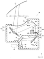
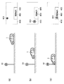
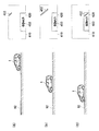
- FIG. 1 It is a block diagram which shows the example of a structure of the display apparatus for vehicles of this invention. It is sectional drawing of the optical system shown by FIG. It is a figure which shows the example of the virtual image seen from the user sitting in the driver's seat of a vehicle provided with the display apparatus for vehicles shown by FIG. It is a figure which shows the relationship between the drawing area in the display shown in FIG. 1, and the 1st screen and 2nd screen shown in FIG. It is a figure explaining the example of the change of the virtual image visually recognized by the user, when the vehicle is drive
- the z-axis is defined in the vehicle front-rear direction with the traveling direction of the vehicle 1 as the vehicle front direction, and the y-axis in the vertical direction.
- the x-axis is defined in the left-right direction (vehicle left-right direction) facing the front direction of the vehicle.
- the x-axis positive direction represents the left direction of the vehicle
- the y-axis positive direction represents the upper side in the vertical direction (upward in real space)
- the z-axis positive direction represents the front direction of the vehicle.
- the vehicular display device 10 includes an image generation unit 20, a display 30, an optical system 40, and a screen 60 including a first screen 61 and a second screen 62.
- the vehicle display device 10 may further include a front information acquisition unit 50.
- the image generation unit 20 includes a processing unit 21 and a storage unit 22.
- the processing unit 21 includes, for example, one or a plurality of microprocessors, a microcontroller, an ASIC (Application Specific Integrated Circuit), an FPGA (Field-Programmable Gate Array), and any other IC (Integrated Circuit).
- the storage unit 22 is, for example, a rewritable RAM (Random Access Memory), a read-only ROM (Read Only Memory), an erasable program read-only EEPROM (Electrically-Erasable Programmable Read-Only Memory), or a nonvolatile memory. It has one or a plurality of memories capable of storing programs and / or data such as a flash memory.
- the image generation unit 20 generates an image, for example, when the processing unit 21 executes a program stored in the storage unit 22.
- the image generation unit 20 is, for example, a front information acquisition unit 50, a vehicle speed detection unit 6, a navigation device 7, a fuel amount detection unit 8, a device (not shown) via a bus 5 such as CAN (Controller Area Network) bus communication. It can be reflected in an image generated by inputting a signal from an ECU or the like.
- CAN Controller Area Network
- the display 30 is a projector having a display element 31 such as a DMD (Digital Micromirror Device) or a liquid crystal light valve.
- the display device 30 is configured to draw an image input from the image generation unit 20 on the display element 31 and to project the light 80 constituting the drawn image.
- the light 80 constituting the drawn image is also referred to as image light 80.
- the optical system 40 is provided, for example, on the lower side of the dashboard 4 and guides the image light 80 projected from the display unit 30 to the first screen 61 and the second screen 62.
- the image light 80 is further imaged and transmitted by the first screen 61 and the second screen 62, reflected by the translucent member 2 such as the front window shield 2 of the vehicle 1, and the driver's seat. It guides so that it may inject into the eyebox of the user 100 who sits down.
- the configuration of the optical system 40 will be described later.
- the user 100 sitting in the driver's seat can visually recognize the virtual image 400 formed on the front side of the vehicle with respect to the front window shield 2.
- the virtual image 400 includes a virtual image 400-1 formed on the first screen 61 and a virtual image 400-2 formed on the second screen 62.
- the virtual image 400-1 is formed so as to be visually recognized by the user 100 sitting in the driver's seat on the front side of the vehicle with respect to the virtual image 400-2.
- the user 100 sitting in the driver's seat is also simply referred to as the user 100.
- the front information acquisition unit 50 includes, for example, a front image acquisition unit 51 and a front image analysis unit 52.
- the forward information acquisition unit 50 is configured to detect the position of the lane of the road in the forward direction of the vehicle, the position information of other vehicles and obstacles existing in the forward direction of the vehicle, the information on the road sign in the forward direction of the vehicle, etc. Get information.
- the front image acquisition unit 51 is, for example, a camera outside the vehicle that captures an image in front of the vehicle.
- the front image acquisition unit 51 may be, for example, a shared vehicle camera used in a drive recorder or the like, or a vehicle camera dedicated to the vehicle display device 10.
- the camera outside the vehicle may be a monocular camera, but it is preferable that the camera outside the vehicle is a stereo camera in order to accurately acquire the distance between the object existing ahead of the vehicle and the host vehicle 1.
- the camera outside the vehicle may be capable of infrared imaging so that an image ahead of the vehicle can be taken even when the vehicle front is dark.
- the front image acquisition unit 51 outputs the acquired image ahead of the vehicle to the front image analysis unit 52, for example.
- the front image analysis unit 52 analyzes the input image ahead of the vehicle using, for example, known image processing, a pattern matching method, or the like.
- the front image analysis unit 52 analyzes the input image ahead of the vehicle to obtain forward information about the road shape ahead of the vehicle (lane, white line, yellow line, stop line, pedestrian crossing, road width, number of lanes, intersection, Curve, branch road, etc.). Further, the front image analysis unit 52 analyzes the input image in front of the vehicle, so that the position and size of other vehicles and obstacles existing in front of the vehicle, the distance from the own vehicle 1, and the own vehicle 1 Forward information such as the relative speed of the vehicle, the type of sign existing in front of the vehicle, and the distance to the host vehicle 1.
- the front image analysis unit 52 outputs the acquired front information to the image generation unit 20 via the bus 5.
- the front image analysis unit 52 may be provided, for example, in a camera outside the vehicle, and the image generation unit 20 may include the function of the front image analysis unit 52. Further, the image generation unit 20 may directly input the front information from the front image analysis unit 52 without using the bus 5.
- the image generation unit 20 may generate a notification signal for reproducing a sound source from at least one speaker 9 mounted on the vehicle 1.
- the at least one speaker 9 may be a dedicated speaker 9 for the vehicle display device 10, or may be a shared speaker 9 such as a speaker of an audio device or the like that is mounted on the vehicle 1 (not shown). The timing at which the image generation unit 20 generates the notification signal will be described later.
- the optical system 40 includes a first plane mirror 41, a reflecting mirror 42, a second plane mirror 43, a concave mirror 44, and a field lens 45. As shown in FIG. 2, the first plane mirror 41, the second plane mirror 43, the reflecting mirror 42, and the concave mirror 44 are disposed inside the case 70 together with the display 30, the first screen 61, and the second screen 62. Yes.
- the case 70 has an upper case 72 covered with a lower case 71 that opens upward.
- the lower case 71 and the upper case 72 are made of, for example, a synthetic resin having a black light shielding property.
- An opening 72 a is formed on the upper surface of the upper case 72.
- a transparent resin cover 73 is provided in the opening 72a.
- an inner lid 74 may be disposed inside the lower case 71 in order to block light from the outside such as sunlight.
- the inner lid 74 is made of, for example, a black synthetic resin having a light shielding property.
- the inner lid 74 is partially formed with an opening 74 a so as to allow the image light 80 projected from the display 30 to pass therethrough.
- the first plane mirror 41 of the optical system 40 is supported by a stay (not shown) fixed to the side wall of the lower case 71.
- the first plane mirror 41 is obtained by forming a reflective film on the surface of a base material made of synthetic resin or glass material by means such as vapor deposition.
- the first plane mirror 41 reflects the image light 80 projected from the display device 30 toward the reflecting mirror 42.
- the reflecting mirror 42 of the optical system 40 is supported by a stay (not shown) fixed to the side wall of the lower case 71.
- the reflecting mirror 42 is formed by, for example, forming a reflecting film on the surface of a base material made of synthetic resin or glass material by means such as vapor deposition.
- the surface of the reflecting mirror 42 is constituted by a first reflecting surface 42-1 and a second reflecting surface 42-2.
- the first reflecting surface 42-1 is formed in a plane mirror shape.
- the second reflecting surface 42-2 is formed in a convex mirror shape.
- the second reflecting surface 42-2 has, for example, a free curved surface.
- the first reflecting surface 42-1 and the second reflecting surface 42-2 are formed on one base material.
- the first screen 61 transmits the image light 80 reflected by the first reflecting surface 42-1.
- the image light 80 reflected by the first reflecting surface 42-1 is light constituting the first portion of the image drawn on the display element 31 by the display device 30, and hereinafter, the first image is displayed. Also called light 80-1.
- the first screen 61 receives the first image light 80-1 on the surface on the negative side of the y axis and forms an image on the surface on the positive side of the y axis, whereby the image drawn on the display element 31 in the display 30 It is the transmissive screen which displays the 1st part of the above on the surface of the y-axis positive side.
- a holographic diffuser, a microlens array, a diffusion plate, or the like can be used for example.
- the second screen 62 transmits the image light 80 reflected by the second reflecting surface 42-2.
- the image light 80 reflected by the second reflecting surface 42-2 is light constituting the second portion of the image drawn on the display element 31 in the display device 30, and hereinafter, the second image Also called light 80-2.
- the second portion of the image drawn on the display element 31 in the display 30 is a portion different from the first portion.
- the second screen 62 receives the second image light 80-2 on the surface on the negative side of the y-axis and forms an image on the surface on the positive side of the y-axis, whereby the image drawn on the display element 31 in the display 30 It is the transmissive screen which displays the 2nd part of the above on the surface of the y-axis positive side.
- a holographic diffuser, a microlens array, a diffusion plate, or the like can be used for the second screen 62.
- the first screen 61 and the second screen 62 are supported by a screen holder 65.
- the screen holder 65 is fixed to a stay or the like (not shown) attached to the side wall of the lower case 71.
- the screen holder 65 includes a first tube portion 66 that supports the first screen 61 and a second tube portion 67 that supports the second screen 62. Further, the first tube portion 66 and the second tube portion 67 are separated by a wall portion 68.
- the second plane mirror 43 of the optical system 40 is supported by a stay (not shown) fixed to the side wall of the upper case 72.
- the second flat mirror 43 is formed, for example, by forming a reflective film on the surface of a base material made of synthetic resin or glass material by means such as vapor deposition.
- the concave mirror 44 of the optical system 40 is rotatably supported on the side wall of the upper case 72.
- the concave mirror 44 is formed, for example, by forming a reflective film on the surface of a base material made of a synthetic resin material by means such as vapor deposition.
- the concave mirror 44 is a mirror having a free-form surface, and further reflects the first image light 80-1 and the second image light 80-2 reflected by the second plane mirror 43 toward the front window shield 2.
- the user 100 has a virtual image 400-1 that is a virtual image of the image formed on the first screen 61 and an image formed on the second screen 62 on the front side of the vehicle with respect to the front window shield 2.
- the length of the optical path of the first image light 80-1 from the first screen 61 to the front window shield 2 is the second image from the second screen 62 to the front window shield 2.
- the first screen 61 and the second screen 62 are arranged in the screen holder 65 so as to be longer than the length of the optical path of the light 80-2.
- the virtual image 400-1 and the virtual image 400-2 visually recognized by the user 100, the virtual image 400-1 is formed on the front side of the vehicle.
- the length of the optical path of the first image light 80-1 from the display 30 to the first screen 61 and the optical path of the second image light 80-2 from the display 30 to the second screen 62 is The optical path of the second image light 80-2 from 30 to the second screen 62 is longer. That is, when the focus of the projection lens (not shown) of the display 30 is set to the position of the first screen 61, the position of the second screen 62 is not focused. Therefore, in the example shown in FIG. 2, the second reflecting surface 42-2 of the reflecting mirror 42 is formed in a convex mirror shape, and the second image light is reflected so as to spread, so that the focal point is positioned at the second screen 62. It is matched.
- the field lens 45 is provided in the second cylindrical portion 67 of the screen holder 65 and closer to the reflecting mirror 42 than the second screen 62.
- the field lens 45 changes the traveling direction of the second image light 80-2 reflected so as to spread radially by the second reflecting surface 42-2 of the reflecting mirror 42 in a narrowing direction, whereby the second image light 80- 2 is provided to transmit the second screen 62.
- a part of the structure of the optical system 40 is different between the display 30 and the first screen 61 and the second screen 62.
- the optical system 40 also exists between the first screen 61 and the second screen 62 and the translucent member 2.
- the enlargement ratio when visually recognized by the user 100 is different.
- the magnification when the second portion is visually recognized by the user 100 as the virtual image 400-2 is as follows: The first portion is larger than the magnification when the user 100 visually recognizes the virtual image 400-1.
- the magnification when the first portion of the image drawn on the display element 31 of the display 30 is visually recognized by the user 100 as the virtual image 400-1 is also referred to as a first magnification.
- an enlargement factor when the second portion is visually recognized by the user 100 as a virtual image 400-2 is also referred to as a second enlargement factor.
- the first enlargement factor and the second enlargement factor are calculated based on, for example, the design values of the display device 10 for the vehicle and the vehicle 1 and the position of the eye box serving as a reference for the user 100 sitting in the driver's seat of the vehicle 1. It may be stored in the storage unit 22 of the generation unit 20. Further, by performing a predetermined calibration process, for example, the stored first enlargement factor and / or second enlargement factor is corrected based on the actual eyebox position of the user 100 sitting in the driver's seat of the vehicle 1. May be.
- the shapes of the first reflecting surface 42-1 and the second reflecting surface 42-2 of the reflecting mirror 42 shown in FIG. 2 are merely examples, and, for example, the first reflecting surface 42-1 is curved rather than flat. It may be a curved surface.
- the second reflecting surface 42-2 of the reflecting mirror 42 may be a flat surface instead of a curved surface, for example.
- both the first reflecting surface 42-1 and the second reflecting surface 42-2 may be curved surfaces.
- the shapes of the first reflecting surface 42-1 and the second reflecting surface 42-2 need to be different from each other. .
- first reflecting surface 42-1 and the second reflecting surface 42-2 of the reflecting mirror 42 is not limited to a curved surface, and both may be configured as a flat surface.
- a first lens and a second lens obtained by dividing a circular lens in the z-axis direction may be provided between the display 30 and the screen holder 65.
- the shape and / or position of the first lens is optimized so that the first image light 80-1 is focused on the first screen 61, and the second image light 80-2 is focused on the second screen 62.
- a method of optimizing the shape and / or position of the second lens may be adopted so as to meet the above. That is, focusing is not performed by changing the shape and / or position of the lens, but by changing the shape of the first reflecting surface 42-1 and the second reflecting surface 42-2 of the reflecting mirror 42. A method may be adopted.
- first reflecting surface 42-1 and the second reflecting surface 42-2 of the reflecting mirror 42 shown in FIG. 2 are formed on one base material, but are not limited thereto. That is, the first reflecting surface 42-1 and the second reflecting surface 42-2 of the reflecting mirror 42 may be formed on separate substrates.
- the second enlargement ratio is larger than the first enlargement ratio.
- the first enlargement ratio is changed to the second enlargement ratio. May be larger.
- the optical axis of the first screen 61 and the optical axis of the second screen 62 correspond to the optical axis of the first image light 80-1 and the optical axis of the second image light 80-2. It is arranged along the optical axis.
- the first screen 61 and / or the second screen 62 may be inclined with respect to the optical axis of the transmitted light.
- the virtual image 400-1 and / or the virtual image 400-2 inclined from the user 100 are visually recognized. .
- FIG. 3 shows only a virtual image among the landscape and the virtual image that can be seen from the user 100 through the front window shield 2.
- the scenery is actually seen through the front window shield 2, but the illustration of the front window shield 2 and the scenery is omitted in FIG.
- FIG. 3 shows a first virtual image area 410 corresponding to the entire first screen 61 and a second virtual image area 420 corresponding to the entire second screen 62. That is, the virtual image 400 is formed only in the first virtual image region 410 and the second virtual image region 420.
- a virtual image mark 451 for informing the presence and type of a road sign, the presence of a lane, A virtual image mark 452 for informing the type is shown.
- the virtual image mark 451 and the virtual image mark 452 illustrated in FIG. 3 are virtual image marks 450 that are visually recognized in a manner that overlaps with the scenery seen through the front window shield 2 from the user 100 sitting in the driver's seat.
- the virtual image mark 450 in the first virtual image area 410 visually recognized by the user 100 include, for example, a virtual image mark that notifies that there is another vehicle or the like ahead of the vehicle 1, or a virtual image that reflects navigation information. There are marks.
- the virtual image mark 450 in the first virtual image region 410 visually recognized by the user 100 is not limited to the virtual image mark exemplified so far. Note that the virtual image in the first virtual image region 410 visually recognized by the user 100 does not necessarily have to be superimposed on the landscape.
- a virtual image mark 453 for informing the vehicle speed of the vehicle 1 is shown as an example of the virtual image 400 of the image element (mark) imaged on the second screen 62.
- the virtual image mark 453 shown in FIG. 3 is a virtual image mark 450 that does not need to be superimposed on the scenery seen from the user 100 through the front window shield 2.
- the virtual image mark 450 in the second virtual image area 420 visually recognized by the user 100 include a virtual image mark that notifies the remaining amount of fuel, battery, and the like, a virtual image mark that notifies the speed limit, and the like.
- the virtual image mark 450 of the second virtual image region 420 visually recognized by the user 100 is not limited to the virtual image mark exemplified so far.
- the first virtual image area 410 is superimposed with the scenery seen through the front window shield 2 to form a virtual image or the like that calls attention to the user 100 compared to the second virtual image area 420. It is an area. That is, the first virtual image area 410 may be used for notifying information with a higher degree of attention than the second virtual image area 420. Therefore, when the virtual image mark 450 is moved between the first virtual image region 410 and the second virtual image region 420, an image in which the virtual image mark 450 is visually recognized is larger in the first virtual image region 410. It is preferably generated by the generation unit 20.
- FIG. 4A shows an example in which the display element 31 of the display 30 is viewed from below.
- FIG. 4B shows an example of the first virtual image region 410 and the second virtual image region 420 viewed from the user 100 sitting in the driver's seat of the vehicle 1. Note that the example shown in FIG. 4B is a case where the configuration of the optical system 40 shown in FIG. 2 and the arrangement of the first screen 61 and the second screen 62 are adopted.
- the virtual image 400 is visually recognized by the user 100 in a distorted state due to the curvature of the optical system 40, the front window shield 2, and the like.
- the image generation unit 20 generates an image in a previously distorted state in consideration of the curvature of the optical system 40, the front window shield 2, and the like as distortion correction.
- the virtual image 400 having no or little distortion is visually recognized by the user 100.
- distortion correction is omitted in the following explanation.
- the ix axis is defined in the horizontal direction and the iy axis is defined in the vertical direction when the display element 31 of the display 30 is viewed from below.
- the x axis and the y axis are shown.
- the ix axis on the display element 31 corresponds to the x axis in the real space
- the iy axis on the display element 31 corresponds to the y axis in the real space.
- the display element 31 includes a first drawing area 36, a second drawing area 37, and a third drawing area 38.
- the first drawing area 36 is an area in which a first portion of an image drawn on the display element 31 is drawn.
- the second drawing area 37 is an area in which a second portion of the image drawn on the display element 31 is drawn.
- the third drawing area 38 is located between the first drawing area 36 and the second drawing area 37.
- the light projected from the third drawing area 38 is guided to the wall 68 of the screen holder 65 by the optical system 40 shown in FIG. That is, even if an image element is displayed in the third drawing area 38, the virtual image is not visually recognized by the user 100 sitting in the driver's seat. Therefore, the image generation unit 20 does not need to generate any image element in the portion to be drawn in the third drawing area 38 of the generated image.
- first drawing area 36, the second drawing area 37, and the third drawing area 38 are merely called for the sake of convenience. That is, the display 30 and the display element 31 need not be individually controlled in each region.
- FIG. 4A shows an example in which an image including the image element 210 in the first portion and the image element 220 in the second portion is drawn on the display element 31 of the display 30. Yes.
- the length 210x of the image element 210 in the ix axis direction is the same as the length 220x of the image element 220 in the ix axis direction.
- 210y which is the length of the image element 210 in the iy-axis direction
- 220y which is the length of the image element 220 in the iy-axis direction
- the virtual image mark 460 shown in FIG. 4B is visually recognized by the user 100 when the image element 210 is drawn in the first drawing area 36 on the display element 31 as in the example shown in FIG.
- the virtual image mark 450 is displayed.
- 460x shown in FIG. 4B is an apparent size of the virtual image mark 460 from the user 100 in the x-axis direction.
- 460y shown in FIG. 4B is the apparent size of the virtual image mark 460 in the y-axis direction from the user 100.
- the virtual image mark 470 shown in FIG. 4B is displayed when the image element 220 is drawn in the second drawing area 37 on the display element 31 as in the example shown in FIG.
- This is a virtual image mark 450 visually recognized by 100.
- 470x shown in FIG. 4B is the apparent size of the virtual image mark 470 in the x-axis direction from the user 100.
- 470y shown in FIG. 4B is an apparent size in the y-axis direction of the virtual image mark 470 from the user 100.
- 460x, 460y, 470x, and 470y are the apparent sizes of the virtual image mark 450 from the user 100 because the actual size and the apparent size of the virtual image mark 450 are different. To clarify that it is a size.
- the reason why the actual size and the apparent size of the virtual image mark 450 are different is that the first virtual image region 410 is formed on the front side of the vehicle from the second virtual image region 420 when viewed from the user 100.
- the first magnification ratio includes a first enlargement ratio in the horizontal direction (ix-axis direction and x-axis direction) and a first enlargement ratio in the vertical direction (iy-axis direction and y-axis direction).
- the second enlargement ratio includes a second enlargement ratio in the horizontal direction and a second enlargement ratio in the vertical direction. That is, the second magnification in the horizontal direction is larger than the first magnification in the horizontal direction, and the second magnification in the vertical direction is larger than the first magnification in the vertical direction.
- the apparent size from the user 100 in the x-axis direction is 460x
- the virtual image mark 470 is the apparent size from the user 100 in the x-axis direction.
- 470x is larger than a certain 470x.
- 460y which is an apparent size in the y-axis direction from the user 100 in the virtual image mark 460 shown in FIG. 4B and an apparent size in the y-axis direction from the user 100 in the virtual image mark 470.
- 470y is larger than 470y.
- the first enlargement ratio is larger than the second enlargement ratio.
- the second screen 62 is larger than the first screen 61 and image elements are imaged.
- the virtual image mark 450 in the second virtual image region 420 (virtual image mark 470 in the example of FIG. 4B) is changed to the virtual image mark 450 in the first virtual image region 410 (the virtual image mark 460 in the example of FIG. 4B). )
- the first magnification in the horizontal direction is obtained by 460x / 210x using the symbols shown in FIGS. 4A and 4B, and the first magnification in the vertical direction is obtained by 460y / 210y.
- the second magnification in the horizontal direction is obtained by 470x / 220x, and the second magnification in the vertical direction is obtained by 470y / 220y.
- a situation may occur in which the virtual image mark 450 visually recognized by the user 100 in the first virtual image area 410 is moved so as to be visually recognized in the second virtual image area 420.
- this is a situation in which the vehicle 1 travels on a road with a road sign ahead.
- a virtual image mark 450 representing the road sign is formed in the first virtual image area 410 in a manner of being superimposed on the road sign as viewed from the user 100.
- a virtual image mark 450 representing the road sign is formed in the second virtual image area 420 in a manner that does not overlap with the road sign when viewed from the user 100.
- the image generation unit 20 generates an image so that the image element 200 included in the first part of the generated image is included in the second part instead of the first part.
- the image generation unit 20 has a size that is visually recognized by the user 100 as the virtual image mark 450 (the virtual image mark 470 in the example of FIG. 4B) on the second virtual image region 420.
- the size of the image element 200 on the display element 31 is determined so as to be equal to or smaller than the size when it is visually recognized by the user 100 as the virtual image mark 450 (virtual image mark 460 in the example of FIG. 4B). Is generated.
- the second enlargement factor is set according to the relationship between the first enlargement factor and the second enlargement factor.
- the size of the virtual image mark 450 in the virtual image area 420 is visually recognized by the user 100 so as to change against the intention of the user 100.
- the second enlargement ratio is larger than the first enlargement ratio
- the size of the virtual image mark 450 in the second virtual image area 420 is visually recognized by the user 100 so as to become larger than the user 100 intends.
- the vehicular display device 10 of the present invention can reduce such a sense of discomfort given to the user.
- the image generation unit 20 when moving the virtual image mark 450 in the second virtual image area 420 into the first virtual image area 410, the image generation unit 20 was included in the second part of the generated image.
- the image is generated so that the image element 200 is included in the first part rather than the second part.
- the image generation unit 20 has a size that is visually recognized by the user 100 as the virtual image mark 450 (the virtual image mark 460 in the example of FIG. 4B) on the first virtual image area 410.
- the size of the image element 200 on the display element 31 is determined so as to be equal to or larger than the size when it is visually recognized by the user 100 as the virtual image mark 450 (virtual image mark 470 in the example of FIG. 4B). Is generated.
- the first enlargement factor and the second enlargement factor are set according to the relationship between the first enlargement factor and the second enlargement factor.
- the size of the virtual image mark 450 in the virtual image region 410 is visually recognized so as to change contrary to the intention of the user 100.
- the second magnification rate is larger than the first magnification rate
- the size of the virtual image mark 450 in the first virtual image area 410 is visually recognized so as to be smaller than the user 100 intends.
- the vehicular display device 10 of the present invention can reduce such a sense of discomfort given to the user.
- 460x is represented by 210x ⁇ first horizontal magnification.
- 470x is represented by 220x ⁇ second horizontal magnification.
- 460y is represented by 210y ⁇ first magnification in the vertical direction.
- 470y is represented by 220y ⁇ second vertical magnification.
- the image generation unit 20 sets the horizontal size 220x of the image element 200 (image element 220) to be newly included in the second portion to the image element 200 ( It is necessary to determine a value equal to or less than a value obtained by multiplying the horizontal size 210x of the image element 210) by the value obtained by dividing the first magnification in the horizontal direction by the second magnification in the horizontal direction.
- this is expressed by using the reference numerals shown in FIGS. 4A and 4B, it is expressed by the following expression (1).
- the image generation unit 20 uses the image element 200 (image element 200) when the vertical size 220y of the image element 200 (image element 220) to be newly included in the second part is included in the first part. 210) must be determined to be less than or equal to the value obtained by multiplying the vertical size 210y by the value obtained by dividing the first magnification in the vertical direction by the second magnification in the vertical direction.
- this is expressed by using the reference numerals shown in FIGS. 4A and 4B, it is expressed by the following equation (2).
- the image generation unit 20 calculates the above expressions (1) and (2), so that the user 100 visually recognizes the virtual image mark 450 (the virtual image mark 470 in the example of FIG. 4B) on the second virtual image region 420.
- the size of the image element 200 included in the image can be determined.
- the image generation unit 20 uses the image element 200 (image element 220) when the horizontal size 210x of the image element 200 (image element 210) to be newly included in the first portion is included in the second portion. ) In the horizontal direction 220x and multiplied by a value obtained by multiplying the second magnification in the horizontal direction by the first magnification in the horizontal direction.
- this is expressed using the reference numerals shown in FIGS. 4A and 4B, it is expressed by the following equation (3).
- the image generation unit 20 adds the vertical size 210y of the image element 200 (image element 210) to be newly included in the first part to the image element 200 (image element 200) that was included in the second part. 220) must be determined to be equal to or larger than the value obtained by multiplying the vertical size 220y by the value obtained by dividing the second magnification in the vertical direction by the first magnification in the vertical direction.
- this is expressed using the reference numerals shown in FIGS. 4A and 4B, it is expressed by the following expression (4).
- the image generation unit 20 calculates the above expressions (3) and (4), so that the user 100 can visually recognize the virtual image mark 450 (the virtual image mark 460 in the example of FIG. 4B) on the first virtual image region 410.
- the size to be surely equal to or larger than the size when it is visually recognized by the user 100 as the virtual image mark 450 (the virtual image mark 470 in the example of FIG. 4B) on the second virtual image region 420,
- the size of the image element 200 included in the image can be determined.
- the image generation unit 20 generates an image so that the image element 200 included in the first part of the generated image is included in the second part instead of the first part, and / or The notification signal may be generated when the image is generated so that the image element 200 included in the second part of the generated image is included in the first part instead of the second part.
- a sound source is reproduced from at least one speaker 9 mounted on the vehicle 1.
- the user 100 can recognize the movement of the virtual image mark 450 from one of the first virtual image region 410 and the second virtual image region 420 to the other by the sound source, the sense of incongruity can be further reduced.
- a motor mounted in the steering handle may be driven so that a steering handle (not shown) vibrates.
- the notification signal is generated, the user 100 may recognize that the virtual image mark 450 has moved from one of the first virtual image region 410 and the second virtual image region 420 to the other by another method. Good.
- FIG. 5 An example of a change in the virtual image 400 visually recognized by the user 100 when the vehicle 1 is traveling will be described with reference to FIGS.
- the example shown in FIG. 5 is an example when the vehicle 1 is traveling on a road where the speed limit sign 91 exists.
- On the left side of FIG. 5A an example in which a speed limit sign 91 is present in front of the vehicle 1 is shown.
- the right side of FIG. 5A shows an example of a virtual image 400 visually recognized by the user 100 in the example shown on the left side of FIG.
- the user 100 can also see the scenery through the front window shield 2, but this is omitted in FIGS. 5 and 6.
- a virtual image mark 451 for notifying the presence of the speed limit sign 91 is formed in the first virtual image area 410 so as to be superimposed on the speed limit sign 91 as viewed from the user 100. Yes.
- a virtual image mark 453 representing the current vehicle speed of the vehicle 1 is formed in the second virtual image area 420 as viewed from the user 100.
- the left side of FIG. 5B shows an example in which the vehicle 1 is closer to the speed limit sign 91 than the example shown on the left side of FIG.
- the right side of FIG. 5B shows an example of a virtual image 400 visually recognized by the user 100 in the example shown on the left side of FIG.
- the size of the virtual image mark 451 in the first virtual image area 410 is large and the position is moved. Visible by the user 100.
- the left side of FIG. 5 (c) shows an example when the vehicle 1 passes the speed limit sign 91.
- the right side of FIG. 5C shows an example of a virtual image 400 visually recognized by the user 100 in the example shown on the left side of FIG.
- the vehicle 1 has a speed limit sign so that the forward information acquisition unit 50 cannot recognize the speed limit sign 91 or cannot superimpose the virtual image mark 451 on the speed limit sign 91.
- the forward information acquisition unit 50 cannot recognize the speed limit sign 91 or cannot superimpose the virtual image mark 451 on the speed limit sign 91.
- the virtual image mark 451 formed in the first virtual image region 410 as viewed from the user 100 is the same as that shown on the right side of FIG. It is formed in the second virtual image area 420.
- the virtual image mark 451 shown on the right side of FIG. 5C is smaller than the virtual image mark 451 shown on the right side of FIG. Therefore, when the virtual image mark 451 in the first virtual image area 410 is moved into the second virtual image area 420, for example, a feeling of strangeness that the size of the virtual image mark 451 is visually recognized contrary to the intention of the user 100 is given. There is no.
- the example shown in FIG. 6 is an example when the vehicle 1 is traveling on a road on which a yellow line 92 for notifying lane change prohibition exists.
- An example in which a yellow line 92 exists in front of the vehicle 1 is shown on the left side of FIG.
- the right side of FIG. 6A shows an example of a virtual image 400 visually recognized by the user 100 in the example shown on the left side of FIG.
- a virtual image mark 452 is formed in the first virtual image region 410 so as to notify that the lane change is prohibited in a manner of being superimposed on the yellow line 92 when viewed from the user 100. Yes.
- the left side of FIG. 6B shows an example in which the vehicle 1 is closer to the starting point of the yellow line 92 than the example shown on the left side of FIG.
- the right side of FIG. 5B shows an example of a virtual image 400 visually recognized by the user 100 in the example shown on the left side of FIG.
- the size (length) of the virtual image mark 452 in the first virtual image area 410 becomes larger (longer) as the vehicle 1 approaches the starting point of the yellow line 92. As seen by the user 100.
- the left side of FIG. 6C shows an example when the vehicle 1 passes the starting point of the yellow line 92.
- the right side of FIG. 6C shows an example of a virtual image 400 visually recognized by the user 100 in the example shown on the left side of FIG.
- the vehicle 1 passes through the starting point of the yellow line 92 and enters the area where lane change is prohibited, so the first virtual image area 410 has no virtual image mark 452. That is, in the example shown on the right side of FIG. 6B, the virtual image mark 452 in the first virtual image area 410 is in the second virtual image area 420 in the example shown on the right side of FIG. Is visually recognized. If the virtual image mark 452 is visually recognized in the first virtual image area 410 in the state of the example shown on the left side of FIG. 6C, the virtual image mark 452 occupies most of the first virtual image area 410. Therefore, the user 100 may be uncomfortable.
- the virtual image mark 452 shown on the right side of FIG. 6C is smaller than the virtual image mark 452 shown on the right side of FIG. Therefore, when the virtual image mark 452 in the first virtual image region 410 is moved into the second virtual image region 420, for example, a feeling of strangeness is given such that the size of the virtual image mark 452 is visually recognized contrary to the intention of the user 100. There is no.
- the image generation unit 20 of the vehicle display device 10 is configured so that the state of the vehicle 1 is, for example, when the remaining amount of fuel in the vehicle 1 is reduced or when the vehicle 1 is turned on.
- An image may be generated such that the virtual image mark 450 that notifies these states is visually recognized in the first virtual image region 410 when the state changes.
- the user 100 can grasp that the state of the vehicle 1 has changed without lowering the line of sight.
- the image generation unit 20 may generate an image in which the virtual image mark 450 that has been visually recognized in the first virtual image area 410 has moved into the second virtual image area 420.
- the user 100 is not uncomfortable.
- the image generation unit 20 of the vehicle display device 10 of the present invention has a virtual image mark 450 such as an arrow for prompting a left turn or a right turn based on the navigation information input from the navigation device 7, for example, in the second virtual image region 420.
- An image that can be visually recognized may be generated.
- the user 100 can grasp that it is necessary to make a left turn or a right turn on the currently traveling road.
- the virtual image mark 450 that has been visually recognized in the second virtual image region 420 turns left or right in the first virtual image region 410.
- the image generation unit 20 of the vehicle display device 10 for example, when the current vehicle speed of the vehicle 1 exceeds the legal speed, the virtual image mark 450 indicating the current vehicle speed is displayed in the first virtual image region 410. An image that can be visually recognized may be generated. Thereby, the user 100 can surely grasp that the current vehicle speed exceeds the legal speed. Then, when the current vehicle speed of the vehicle 1 is equal to or lower than the legal speed, the virtual image mark 450 representing the current vehicle speed visually recognized in the first virtual image area 410 is moved into the second virtual image area 420. An image may be generated. Thereby, even after the current vehicle speed of the vehicle 1 returns to the legal speed or less, the user 100 is uncomfortable compared to the case where the virtual image mark 450 representing the current vehicle speed is visually recognized in the first virtual image region 410. Don't give.
- the user 100 selects whether to display ON / OFF for a certain type of virtual image mark 450, in the first virtual image region 410 or the second virtual image region 420. Selection, selection of presence / absence of movement between the first virtual image region 410 and the second virtual image region 420, and the like may be settable. However, it is necessary that the display of the vehicle speed or the like is not included in certain types of virtual image marks 450 that can be set. Accordingly, the user 100 can adopt his / her preference while ensuring safety.
- the present invention can be used for a vehicle display device such as a head-up display.
Landscapes
- Engineering & Computer Science (AREA)
- Chemical & Material Sciences (AREA)
- Combustion & Propulsion (AREA)
- Transportation (AREA)
- Mechanical Engineering (AREA)
- Physics & Mathematics (AREA)
- General Physics & Mathematics (AREA)
- Optics & Photonics (AREA)
- Instrument Panels (AREA)
Abstract
ユーザーに与える違和感を軽減する車両用表示装置を提供する。 車両用表示装置10は、画像生成部20が生成した画像のうちの第1部分の虚像400-1と第2部分の虚像400-2とを、車両1の運転席に座るユーザー100に視認させることができる。車両用表示装置10の画像生成部20は、虚像400-1に含まれていた虚像マーク450が虚像400-1ではなく虚像400-2に含まれるようにユーザー100に視認される画像を生成するときに、虚像400-2に含まれるようにユーザー100に視認される虚像マーク450の大きさが虚像400-1に含まれるようにユーザー100に視認されていたときの虚像マーク450の大きさ以下になるように、第2部分に含まれる画像要素200の大きさを決定する。
Description
本発明は、車両用表示装置に関する。本発明は、特に、車両の運転席に座るユーザーが大きな視線移動をすることなく、ユーザーに適切な情報を提供可能な車両用表示装置に関する。
車両用表示装置として、車両のフロントウィンドウシールド等の透光部材に表示画像を投射することによって、フロントウィンドウシールドで反射される表示画像の光を用いて運転席に座ったユーザーに、虚像を視認させる、いわゆるヘッドアップディスプレイがある。このような車両用表示装置では、虚像は、車両のフロントウィンドウシールドを基準にして車両進行方向側(車両前方側)に形成され、運転席に座ったユーザーによって視認される。このような車両用表示装置が備えられている車両の運転席に座るユーザーは、運転中に大きな視線移動を行うことなく、車両用表示装置によって提供される情報を把握することができる。
このような車両用表示装置の例として、例えば、表示画像を構成する光を投射する表示器を2つ備える車両用表示装置がある。このような車両用表示装置は、2つの表示器によって別々の画像を投射することによって、これらの画像の虚像が、車両進行方向において異なった距離に形成され、運転席に座ったユーザーによって視認される。その結果、この2つの虚像が提供する各々の情報の認識性を向上することができる。
ところで、このような車両用表示装置には、2つの表示器を備えることに起因する、車両用表示装置の構造の複雑化及び大型化という問題点があった。そこで、例えば、特許文献1には、1つの表示器と、この1つの表示器から投射される画像の上半分(第1部分)を構成する光が結像されると共に透過する第1スクリーンと、この1つの表示器から投射される画像の下半分(第2部分)を構成する光が結像されると共に透過する第2スクリーンとを備える車両用表示装置が示されている。また、特許文献1に示されている車両用表示装置は、第2スクリーンを、画像を構成する光の進行方向(光路)に沿って移動可能に構成されている。
このように、特許文献1に示されている車両用表示装置は、備える表示器が1つでありながら、表示器が投射する画像の上半分(第1部分)の虚像と下半分(第2部分)の虚像とが、運転席に座ったユーザーにとって、車両進行方向において異なった距離に視認される。すなわち、特許文献1に示されている車両用表示装置は、2つの虚像が提供する各々の情報の認識性を向上と、車両用表示装置の構造の複雑化及び大型化の防止とを両立させることができる。
ところで、特許文献1に示されている車両用表示装置では、表示器から投射される画像の下半分(第2部分)を構成する光の焦点を、第2スクリーンの位置に調整する機構として、光路に沿って移動可能な第2投射レンズが光学系に設けられている。第2投射レンズが光路に沿って移動可能なことによって、特許文献1に示されている車両用表示装置では、表示器から投射される画像が第1スクリーン上に結像される拡大率と第2スクリーン上に結像される拡大率とが異なることを、本発明者らは認識した。
その結果、例えば、画像に含まれるマーク等の画像要素が第1スクリーン上に結像される第1部分から第2スクリーン上に結像される第2部分へ移動するようなときに、この画像要素の虚像の大きさが意図せず拡大されてしまう状況が発生し得ることを、本発明者らは認識した。したがって、特許文献1に示されている車両用表示装置では、ユーザーに違和感を与えてしまう可能性があり、改善の余地がある。
本発明の1つの目的は、ユーザーに与える違和感を軽減する車両用表示装置を提供することにある。本発明の他の目的は、以下に例示する態様及び好ましい実施形態、並びに添付の図面を参照することによって、当業者に明らかになるであろう。
本発明に従う第1の態様は、画像を生成する画像生成部と、
表示素子を有して、前記画像を前記表示素子上に描画すると共に、描画された前記画像を構成する光を投射可能な表示器と、
前記表示器によって描画された前記画像のうちの第1部分を構成する光である第1画像光が結像されると共に透過する第1スクリーンと、
前記表示器によって描画された前記画像のうちの前記第1部分とは異なる部分である第2部分を構成する光である第2画像光が結像されると共に透過する第2スクリーンと、
車両の運転席に座るユーザーから、前記第1スクリーンに結像された前記画像のうちの前記第1部分の虚像と前記第2スクリーンに結像された前記画像のうちの前記第2部分の虚像とが視認されるように、前記表示器によって投射される前記第1画像光及び前記第2画像光を前記車両の透光部材で反射させるように案内する光学系と、
を備え、
前記光学系は、生成された前記画像のうちの前記第1部分が第1拡大率で拡大された状態で前記ユーザーによって前記第1部分の前記虚像が視認されると共に、生成された前記画像のうちの前記第2部分が前記第1拡大率とは異なる拡大率である第2拡大率で拡大された状態で前記ユーザーによって前記第2部分の虚像が視認されるように、前記表示器によって投射される前記第1画像光及び前記第2画像光を前記車両の前記透光部材で反射させるように案内し、
前記画像生成部は、生成した前記画像のうちの前記第1部分に含まれていた画像要素が前記第1部分ではなく前記第2部分に含まれるような画像を生成するときに、前記ユーザーによって視認される前記第2部分に含まれるこの画像要素の虚像の大きさが、この画像要素が前記第1部分に含まれていたときにユーザーによって視認されていたこの画像要素の虚像の大きさ以下になるように、前記第2部分に含まれるこの画像要素の大きさを決定して前記画像を生成する一方で、
前記画像生成部は、生成した前記画像のうちの前記第2部分に含まれていた画像要素が前記第2部分ではなく前記第1部分に含まれるような画像を生成するときに、前記ユーザーによって視認される前記第1部分に含まれるこの画像要素の虚像の大きさが、この画像要素が前記第2部分に含まれていたときにユーザーによって視認されていたこの画像要素の虚像の大きさ以上になるように、前記第1部分に含まれるこの画像要素の大きさを決定して前記画像を生成する車両用表示装置に関する。
表示素子を有して、前記画像を前記表示素子上に描画すると共に、描画された前記画像を構成する光を投射可能な表示器と、
前記表示器によって描画された前記画像のうちの第1部分を構成する光である第1画像光が結像されると共に透過する第1スクリーンと、
前記表示器によって描画された前記画像のうちの前記第1部分とは異なる部分である第2部分を構成する光である第2画像光が結像されると共に透過する第2スクリーンと、
車両の運転席に座るユーザーから、前記第1スクリーンに結像された前記画像のうちの前記第1部分の虚像と前記第2スクリーンに結像された前記画像のうちの前記第2部分の虚像とが視認されるように、前記表示器によって投射される前記第1画像光及び前記第2画像光を前記車両の透光部材で反射させるように案内する光学系と、
を備え、
前記光学系は、生成された前記画像のうちの前記第1部分が第1拡大率で拡大された状態で前記ユーザーによって前記第1部分の前記虚像が視認されると共に、生成された前記画像のうちの前記第2部分が前記第1拡大率とは異なる拡大率である第2拡大率で拡大された状態で前記ユーザーによって前記第2部分の虚像が視認されるように、前記表示器によって投射される前記第1画像光及び前記第2画像光を前記車両の前記透光部材で反射させるように案内し、
前記画像生成部は、生成した前記画像のうちの前記第1部分に含まれていた画像要素が前記第1部分ではなく前記第2部分に含まれるような画像を生成するときに、前記ユーザーによって視認される前記第2部分に含まれるこの画像要素の虚像の大きさが、この画像要素が前記第1部分に含まれていたときにユーザーによって視認されていたこの画像要素の虚像の大きさ以下になるように、前記第2部分に含まれるこの画像要素の大きさを決定して前記画像を生成する一方で、
前記画像生成部は、生成した前記画像のうちの前記第2部分に含まれていた画像要素が前記第2部分ではなく前記第1部分に含まれるような画像を生成するときに、前記ユーザーによって視認される前記第1部分に含まれるこの画像要素の虚像の大きさが、この画像要素が前記第2部分に含まれていたときにユーザーによって視認されていたこの画像要素の虚像の大きさ以上になるように、前記第1部分に含まれるこの画像要素の大きさを決定して前記画像を生成する車両用表示装置に関する。
仮に、画像生成部が、表示素子上に描画される画像要素の大きさを変更せずに、画像を生成したとすると、第1拡大率と第2拡大率との関係によって、運転席に座ったユーザーによって視認される画像要素の虚像の大きさがユーザーの意に反した変化をする可能性がある。本発明の車両用表示装置は、このようなユーザーに与える違和感を軽減することができる。
本発明に従う第2の態様では、第1の態様において、前記光学系は、前記第2拡大率が前記第1拡大率よりも大きくなるように構成され、
前記画像生成部は、生成した前記画像のうちの前記第1部分に含まれていた前記画像要素が前記第1部分ではなく前記第2部分に含まれるような画像を生成するときに、前記第2部分に含まれるこの画像要素の前記画像上の縦方向の大きさが、前記縦方向における前記第1拡大率を前記縦方向における前記第2拡大率で割って得た値を、前記第1部分に含まれていたときのこの画像要素の前記縦方向の大きさに掛けて得た大きさ以下になり、且つ、
前記第2部分に含まれるこの画像要素の前記画像上の横方向の大きさが、前記横方向における前記第1拡大率を前記横方向における前記第2拡大率で割って得た値を、前記第1部分に含まれていたときのこの画像要素の前記横方向の大きさに掛けて得た大きさ以下になるように、この画像要素の大きさを決定して前記画像を生成する一方で、
前記画像生成部は、生成した前記画像のうちの前記第2部分に含まれていた前記画像要素が前記第2部分ではなく前記第1部分に含まれるような画像を生成するときに、前記第1部分に含まれるこの画像要素の前記画像上の縦方向の大きさが、前記縦方向における前記第2拡大率を前記縦方向における前記第1拡大率で割って得た値を、前記第2部分に含まれていたときのこの画像要素の前記縦方向の大きさに掛けて得た大きさ以上になり、且つ、
前記第1部分に含まれる前記画像要素の前記画像上の横方向の大きさが、前記横方向における前記第2拡大率を前記横方向における前記第1拡大率で割って得た値を、前記第2部分に含まれていたときのこの画像要素の前記横方向の大きさに掛けて得た大きさ以下になるように、この画像要素の大きさを決定して前記画像を生成してもよい。
前記画像生成部は、生成した前記画像のうちの前記第1部分に含まれていた前記画像要素が前記第1部分ではなく前記第2部分に含まれるような画像を生成するときに、前記第2部分に含まれるこの画像要素の前記画像上の縦方向の大きさが、前記縦方向における前記第1拡大率を前記縦方向における前記第2拡大率で割って得た値を、前記第1部分に含まれていたときのこの画像要素の前記縦方向の大きさに掛けて得た大きさ以下になり、且つ、
前記第2部分に含まれるこの画像要素の前記画像上の横方向の大きさが、前記横方向における前記第1拡大率を前記横方向における前記第2拡大率で割って得た値を、前記第1部分に含まれていたときのこの画像要素の前記横方向の大きさに掛けて得た大きさ以下になるように、この画像要素の大きさを決定して前記画像を生成する一方で、
前記画像生成部は、生成した前記画像のうちの前記第2部分に含まれていた前記画像要素が前記第2部分ではなく前記第1部分に含まれるような画像を生成するときに、前記第1部分に含まれるこの画像要素の前記画像上の縦方向の大きさが、前記縦方向における前記第2拡大率を前記縦方向における前記第1拡大率で割って得た値を、前記第2部分に含まれていたときのこの画像要素の前記縦方向の大きさに掛けて得た大きさ以上になり、且つ、
前記第1部分に含まれる前記画像要素の前記画像上の横方向の大きさが、前記横方向における前記第2拡大率を前記横方向における前記第1拡大率で割って得た値を、前記第2部分に含まれていたときのこの画像要素の前記横方向の大きさに掛けて得た大きさ以下になるように、この画像要素の大きさを決定して前記画像を生成してもよい。
第2の態様において、画像生成部は、画像要素が第2部分に含まれる虚像の大きさが、確実に、この画像要素が第1部分に含まれていたときの虚像の大きさ以下になるように、又は、画像要素が第1部分に含まれる虚像の大きさが、確実に、この画像要素が第2部分に含まれていたときの虚像の大きさ以上になるように、画像に含ませる画像要素の大きさを決定することができる。
本発明に従う第3の態様では、第1又は第2の態様において、前記画像生成部は、生成した前記画像のうちの前記第1部分に含まれていた前記画像要素が前記第1部分ではなく前記第2部分に含まれるような画像を生成するとき、及び/又は、生成した前記画像のうちの前記第2部分に含まれていた前記画像要素が前記第2部分ではなく前記第1部分に含まれるような画像を生成するときに、報知信号を生成してもよい。
第3の態様において、運転席に座ったユーザーによって視認される画像要素の虚像が第1スクリーンに対応する位置と第2スクリーンに対応する位置との間で移動することを、ユーザーに対して報知することができる。
本発明に従う第4の態様では、第3の態様において、前記報知信号は、前記車両が搭載する少なくとも1つのスピーカから所定の音源を再生させる信号であってもよい。
第4の態様において、ユーザーは、視認する画像要素の虚像が第1スクリーンに対応する位置と第2スクリーンに対応する位置との間で移動することを、音源によっても認識できる。
以下に説明する好ましい実施形態は、本発明を容易に理解するために用いられている。従って、当業者は、本発明が、以下に説明される実施形態によって不当に限定されないことを留意すべきである。
図1を参照して、本発明の車両用表示装置10の全体の構成の例を説明する。以下の説明を容易にするために、図1に示されるように、実空間において、例えば、車両1の進行方向を車両前方向とした車両前後方向にz軸を規定し、鉛直方向にy軸を規定し、車両前方向を向いて左右方向(車両左右方向)にx軸を規定する。このとき、x軸正方向は車両左方向を表し、y軸正方向は鉛直方向上側(実空間上における上方向)を表し、z軸正方向は車両前方向を表す。
図1に示されるように、車両用表示装置10は、画像生成部20と表示器30と光学系40と第1スクリーン61及び第2スクリーン62を含むスクリーン60とを備える。車両用表示装置10は、前方情報取得部50をさらに備えてもよい。
画像生成部20は、処理部21と記憶部22とを含む。処理部21は、例えば、1又は複数のマイクロプロセッサ、マイクロコントローラ、ASIC(Application Specific Integrated Circuit)、FPGA(Field-Programmable Gate Array)、任意の他のIC(Integrated Circuit)等を有する。記憶部22は、例えば、書き換え可能なRAM(Random Access Memory)、読み出し専用のROM(Read Only Memory)、消去不能なプログラム読み出し専用のEEPROM(Electrically Erasable Programmable Read-Only Memory)、不揮発性メモリであるフラッシュメモリ等のプログラム及び/又はデータを記憶可能な1又は複数のメモリを有する。
画像生成部20は、例えば、記憶部22に記憶されているプログラムを処理部21が実行することによって、画像を生成する。画像生成部20は、CAN(Controller Area Network)バス通信等のバス5を介して、例えば、前方情報取得部50、車速検出部6、ナビゲーション装置7、燃料量検出部8、図示されていない装置、ECU等から信号を入力することによって生成する画像に反映させることができる。
表示器30は、例えば、DMD(Digital Micromirror Device)、液晶ライトバルブ等の表示素子31を有する、プロジェクタである。すなわち、表示器30は、画像生成部20から入力する画像を表示素子31上に描画すると共に、この描画された画像を構成する光80を投射可能に構成されている。描画された画像を構成する光80を、以下、画像光80とも呼ぶ。
光学系40は、例えば、ダッシュボード4の下側に設けられ、第1スクリーン61及び第2スクリーン62へ表示器30から投射される画像光80を案内する。光学系40は、さらに、画像光80が、第1スクリーン61及び第2スクリーン62で結像されると共に透過され、車両1のフロントウィンドウシールド2等の透光部材2で反射され、運転席に座るユーザー100のアイボックスに入射されるように案内する。光学系40の構成については後述する。
運転席に座るユーザー100は、フロントウィンドウシールド2を基準にして車両前方側に形成される虚像400を視認することができる。虚像400には、第1スクリーン61に結像された像の虚像400-1と、第2スクリーン62に結像された像の虚像400-2とが含まれる。なお、詳しくは後述するが、虚像400-1は、運転席に座るユーザー100にとって、虚像400-2よりも車両前方向側に視認されるように形成される。以下、運転席に座るユーザー100を、単にユーザー100とも呼ぶ。
前方情報取得部50は、例えば、前方画像取得部51と前方画像解析部52とを含む。前方情報取得部50は、例えば、車両前方向の道路の車線の位置情報、車両前方向に存在する他の車両及び障害物等の位置情報、車両前方向の道路標識の情報等の車両前方の情報を取得する。
前方画像取得部51は、例えば、車両前方の画像を撮像する車外カメラである。前方画像取得部51は、例えば、ドライブレコーダー等に用いられている共用の車外カメラ等であってもよく、車両用表示装置10専用の車外カメラ等であってもよい。また、車外カメラは、単眼カメラであってもよいが、車両前方に存在する物体と自車両1との距離を正確に取得するために、車外カメラはステレオカメラであることが好ましい。また、車外カメラは、車両前方が暗いときであっても車両前方の画像を撮像できるように、赤外線撮像が可能であってもよい。前方画像取得部51は、例えば、取得した車両前方の画像を前方画像解析部52に出力する。
前方画像解析部52は、例えば、公知の画像処理、パターンマッチング手法等を用いて、入力した車両前方の画像を解析する。前方画像解析部52は、入力した車両前方の画像を解析することによって、車両前方の道路形状に関する前方情報(車線、白線、黄線、停止線、横断歩道、道路の幅員、車線数、交差点、カーブ、分岐路等)を取得する。また、前方画像解析部52は、入力した車両前方の画像を解析することによって、車両前方に存在する他の車両、障害物等の位置、大きさ、自車両1との距離、自車両1との相対速度、車両前方に存在する標識の種類及び自車両1との距離等の前方情報を取得する。前方画像解析部52は、例えば、取得した前方情報をバス5を介して、画像生成部20に出力する。ここで、前方画像解析部52は、例えば、車外カメラの中に含まれて設けられていてもよく、画像生成部20が前方画像解析部52の機能を含んでもよい。また、画像生成部20は、バス5を介さずに前方画像解析部52から前方情報を直接入力してもよい。
また、画像生成部20は、車両1が搭載する少なくとも1つのスピーカ9から音源を再生させる報知信号を生成してもよい。少なくとも1つのスピーカ9は、車両用表示装置10の専用のスピーカ9であってもよく、例えば図示されていない車両1が搭載するオーディオ装置等のスピーカ等の共用のスピーカ9であってもよい。なお、画像生成部20が報知信号を生成するタイミングについては、後述する。
図2を用いて、光学系40の構成の例を説明する。光学系40は、第1平面鏡41、反射鏡42、第2平面鏡43、凹面鏡44及びフィールドレンズ45を含む。図2に示されているように、第1平面鏡41、第2平面鏡43、反射鏡42及び凹面鏡44は、表示器30、第1スクリーン61及び第2スクリーン62と共にケース70の内側に配置されている。
ケース70は、上方に向かって開口した下ケース71に、上ケース72が被されている。下ケース71及び上ケース72は、例えば、黒色の遮光性を有する合成樹脂によって形成されている。上ケース72の上面には、開口部72aが形成されている。この開口部72aには、例えば、透明樹脂製のカバー部73が設けられている。
また、下ケース71の内部に、太陽光等の外部からの光を遮るために中蓋74が配置されてもよい。中蓋74は、例えば、黒色の遮光性を有する合成樹脂によって形成されている。中蓋74は、表示器30から投射された画像光80の通過を許容するよう、一部に開口部74aが形成されている。
光学系40の第1平面鏡41は、下ケース71の側壁に固定された図示されていないステー等によって支持されている。第1平面鏡41は、例えば、合成樹脂やガラス材料からなる基材の表面に、蒸着等の手段により反射膜を形成したものである。第1平面鏡41は、表示器30から投射される画像光80を反射鏡42に向けて反射する。
光学系40の反射鏡42は、下ケース71の側壁に固定された図示されていないステー等によって支持されている。反射鏡42は、例えば、合成樹脂やガラス材料からなる基材の表面に、蒸着等の手段により反射膜を形成したものである。
反射鏡42の表面は、第1反射面42-1及び第2反射面42-2によって構成されている。第1反射面42-1は平面鏡状に形成される。第2反射面42-2は凸面鏡状に形成される。第2反射面42-2は例えば自由曲面を有する。第1反射面42-1及び第2反射面42-2は1つの基材上に形成されている。
第1スクリーン61は、第1反射面42-1において反射された画像光80を透過する。ここで、第1反射面42-1において反射された画像光80は、表示器30において表示素子31上に描画された画像のうちの第1部分を構成する光であり、以下、第1画像光80-1とも呼ぶ。
第1スクリーン61は、第1画像光80-1をy軸負側の面で受光してy軸正側の面に結像させることによって、表示器30において表示素子31上に描画された画像のうちの第1部分をy軸正側の面に表示する透過スクリーンである。第1スクリーン61には、例えば、ホログラフィックディフューザ、マイクロレンズアレイ、拡散板等を採用することができる。
第2スクリーン62は、第2反射面42-2において反射された画像光80を透過する。ここで、第2反射面42-2において反射された画像光80は、表示器30において表示素子31上に描画された画像のうちの第2部分を構成する光であり、以下、第2画像光80-2とも呼ぶ。なお、表示器30において表示素子31上に描画された画像のうちの第2部分は、第1部分とは異なる部分である。
第2スクリーン62は、第2画像光80-2をy軸負側の面で受光してy軸正側の面に結像させることによって、表示器30において表示素子31上に描画された画像のうちの第2部分をy軸正側の面に表示する透過スクリーンである。第2スクリーン62には、第1スクリーン61と同様に、例えば、ホログラフィックディフューザ、マイクロレンズアレイ、拡散板等を採用することができる。
第1スクリーン61及び第2スクリーン62は、スクリーンホルダ65によって、支持されている。スクリーンホルダ65は、下ケース71の側壁に取り付けられた図示されていないステー等に固定されている。スクリーンホルダ65は、第1スクリーン61を支持している第1筒部66と、第2スクリーン62を支持している第2筒部67と、からなる。また、第1筒部66と第2筒部67との間は、壁部68で隔てられている。
光学系40の第2平面鏡43は、上ケース72の側壁に固定された図示されていないステー等によって支持されている。第2平面鏡43は、例えば、合成樹脂やガラス材料からなる基材の表面に、蒸着等の手段により反射膜を形成してなる。
光学系40の凹面鏡44は、上ケース72の側壁に回転可能に支持されている。凹面鏡44は、例えば、合成樹脂材料からなる基材の表面に、蒸着等の手段により反射膜を形成してなる。凹面鏡44は、自由曲面を有するミラーであり、第2平面鏡43によって反射した第1画像光80-1及び第2画像光80-2をフロントウィンドウシールド2に向けてさらに反射させる。
フロントウィンドウシールド2で反射された第1画像光80-1及び第2画像光80-2は、上述したように、ユーザー100のアイボックスに入射する。その結果、ユーザー100は、フロントウィンドウシールド2を基準にして車両前方側に、第1スクリーン61に結像される像の虚像である虚像400-1と、第2スクリーン62に結像される像の虚像である虚像400-2とを視認することができる。
ここで、図2に示される例において、第1スクリーン61からフロントウィンドウシールド2までの第1画像光80-1の光路の長さが、第2スクリーン62からフロントウィンドウシールド2までの第2画像光80-2の光路の長さと比較して長くなるように、第1スクリーン61及び第2スクリーン62がスクリーンホルダ65内に配置されている。その結果、ユーザー100に視認される虚像400-1と虚像400-2とでは、虚像400-1の方が車両前方向側に形成される。
また、表示器30から第1スクリーン61までの第1画像光80-1の光路と、表示器30から第2スクリーン62までの第2画像光80-2の光路との長さでは、表示器30から第2スクリーン62までの第2画像光80-2の光路の方が長くなる。すなわち、表示器30の図示されていない投射レンズの焦点が、第1スクリーン61の位置に合わせられているとき、第2スクリーン62の位置にはその焦点が合わない。そのため、図2に示される例では、反射鏡42の第2反射面42-2が凸面鏡状に形成され、第2画像光を広げるように反射することによって、焦点を第2スクリーン62の位置に合わせている。
さらに、図2に示される例においては、フィールドレンズ45が、スクリーンホルダ65の第2筒部67内であって第2スクリーン62よりも反射鏡42側に設けられている。フィールドレンズ45は、反射鏡42の第2反射面42-2によって放射状に広がるように反射された第2画像光80-2の進行方向を狭まる方向に変化させることによって、第2画像光80-2が第2スクリーン62を透過させるために設けられている。
このように、表示器30から第1スクリーン61までと第2スクリーン62までとでは、光学系40の一部の構造が異なる。
このことに加えて、第1スクリーン61及び第2スクリーン62から透光部材2までの間にも光学系40が存在する。これらの結果、表示器30の表示素子31上に描画された画像のうち、第1部分が虚像400-1としてユーザー100に視認されるときの拡大率と、第2部分が虚像400-2としてユーザー100に視認されるときの拡大率とが、異なる。具体的に、図2に示される例においては、表示器30の表示素子31上に描画された画像のうち、第2部分が虚像400-2としてユーザー100に視認されるときの拡大率が、第1部分が虚像400-1としてユーザー100に視認されるときの拡大率よりも大きくなる。
以下、表示器30の表示素子31上に描画された画像のうち、第1部分が虚像400-1としてユーザー100に視認されるときの拡大率を第1拡大率とも呼ぶ。また、表示器30の表示素子31上に描画された画像のうち、第2部分が虚像400-2としてユーザー100に視認されるときの拡大率を第2拡大率とも呼ぶ。第1拡大率及び第2拡大率は、例えば、車両用表示装置10及び車両1の設計値並びに車両1の運転席に座るユーザー100の基準となるアイボックスの位置等に基づいて算出され、画像生成部20の記憶部22に記憶されていてもよい。また、所定のキャリブレーション処理を行うことによって、例えば車両1の運転席に座るユーザー100の実際のアイボックスの位置に基づいて、記憶されている第1拡大率及び/又は第2拡大率を補正してもよい。
なお、図2に示される反射鏡42の第1反射面42-1及び第2反射面42-2の形状は一例に過ぎず、例えば、第1反射面42-1が、平面ではなく湾曲した面である湾曲面であっても良い。このとき、反射鏡42第2反射面42-2が、例えば、湾曲面でなく平面であってもよい。また、第1反射面42-1及び第2反射面42-2の両方が湾曲面であってもよい。第1反射面42-1及び第2反射面42-2が共に湾曲面である場合には、第1反射面42-1及び第2反射面42-2の形状が互いに異なっている必要がある。
また、反射鏡42の第1反射面42-1及び第2反射面42-2の一方又は双方が湾曲面で構成される場合に限らず、双方が平面で構成されてもよい。この場合、例えば、表示器30とスクリーンホルダ65との間に円形状のレンズをz軸方向に分割した第1レンズと第2レンズを設けてもよい。例えば、第1画像光80-1の焦点が第1スクリーン61に合うように、第1レンズの形状及び/又は位置を最適化し、且つ、第2画像光80-2の焦点が第2スクリーン62に合うように、第2レンズの形状及び/又は位置を最適化する方法が採用されてもよい。すなわち、反射鏡42の第1反射面42-1及び第2反射面42-2の形状を変化させることによって焦点を合わせるのではなく、レンズの形状及び/又は位置を変化させることによって焦点を合わせる方式を採用してもよい。
また、図2に示される反射鏡42の第1反射面42-1及び第2反射面42-2は、1つの基材上に形成されているが、これに限らない。すなわち、反射鏡42の第1反射面42-1及び第2反射面42-2が別体の基材上に形成されてもよい。
また、図2に示されている例においては、第2拡大率が第1拡大率よりも大きくなっている。しかしながら、例えば、表示器30を設置する位置、すなわち表示器30から画像光80を投射する方向を変更すること、フィールドレンズ45の形状を変更すること等により、第1拡大率を第2拡大率よりも大きくしてもよい。
さらに、図2に示される例において、第1スクリーン61の光軸及び第2スクリーン62の光軸は、第1画像光80-1の光軸及び第2画像光80-2の光軸の対応する光軸に沿うよう配置されている。しかしながら、第1スクリーン61及び/又は第2スクリーン62を、透過する光の光軸に対して傾けて配置してもよい。第1スクリーン61及び/又は第2スクリーン62が、透過する光の光軸に対して傾けて配置されたときは、ユーザー100から傾いた虚像400-1及び/又は虚像400-2が視認される。
図3を用いて、本発明の車両用表示装置10を備える車両1の運転席に座るユーザー100から見える虚像の例を説明する。図3には、ユーザー100からフロントウィンドウシールド2越しに見える、風景及び虚像のうち、虚像のみが示されている。すなわち、実際には、フロントウィンドウシールド2越しに風景が見えているが、図3においては、フロントウィンドウシールド2及び風景の図示が省略されている。
図3には、第1スクリーン61全体に相当する第1虚像領域410と、第2スクリーン62全体に相当する第2虚像領域420とが示されている。すなわち、第1虚像領域410内及び第2虚像領域420内のみに、虚像400が形成される。
図3において、第1虚像領域410には、第1スクリーン61に結像される画像要素(マーク)の虚像400の例として、道路標識の存在及び種類を報知する虚像マーク451と車線の存在及び種類を報知する虚像マーク452とが示されている。図3に示される虚像マーク451及び虚像マーク452は、運転席に座るユーザー100からフロントウィンドウシールド2越しに見える風景と重畳する態様で視認される虚像マーク450である。
ユーザー100によって視認される第1虚像領域410における虚像マーク450の他の例としては、例えば、車両1の前方に他の車両等が存在することを報知する虚像マーク、ナビゲート情報を反映した虚像マーク等がある。ユーザー100によって視認される第1虚像領域410における虚像マーク450は、ここまでに例示した虚像マークに限定されない。なお、ユーザー100によって視認される第1虚像領域410内の虚像は、必ずしも、風景と重畳する態様である必要はない。
図3において、第2虚像領域420には、第2スクリーン62に結像される画像要素(マーク)の虚像400の例として、車両1の車速を報知する虚像マーク453が示されている。図3に示される虚像マーク453は、ユーザー100からフロントウィンドウシールド2越しに見える風景と重畳する必要がない虚像マーク450である。
ユーザー100によって視認される第2虚像領域420における虚像マーク450の他の例としては、燃料、バッテリ等の残量を報知する虚像マーク、制限速度を報知する虚像マーク等がある。ユーザー100によって視認される第2虚像領域420の虚像マーク450は、ここまでに例示した虚像マークに限定されない。
このように、第1虚像領域410は、フロントウィンドウシールド2越しに見える風景と重畳させること等によって、第2虚像領域420と比較して、ユーザー100に対して注意を促す虚像等が形成される領域である。すなわち、第1虚像領域410は、第2虚像領域420と比較して、注意度が高い情報を報知するために使用されてもよい。したがって、第1虚像領域410及び第2虚像領域420の間で、虚像マーク450が移動するようなときは、第1虚像領域410の方が、虚像マーク450が大きく視認されるような画像が画像生成部20によって生成されることが好ましい。
図4を用いて、表示器30の表示素子31上の領域と、第1虚像領域410及び第2虚像領域420との関係を説明する。図4(a)は、表示器30の表示素子31を見下ろすように見た例を示す。図4(b)は、車両1の運転席に座るユーザー100から見た第1虚像領域410及び第2虚像領域420の例を示す。なお、図4(b)に示される例は、図2に示される光学系40の構成と第1スクリーン61及び第2スクリーン62の配置とを採用した場合のものである。
なお、光学系40、フロントウィンドウシールド2等が湾曲していることに起因し、虚像400は、ユーザー100によって歪んだ状態で視認される。このことを防止するため、画像生成部20は、歪み補正として、光学系40、フロントウィンドウシールド2等の湾曲を考慮して予め歪んだ状態の画像を生成する。歪み補正が実行されることによって、歪みのない又は少ない虚像400がユーザー100によって視認される。しかしながら、説明を容易にするために、歪み補正については以下の説明において省略されている。
図4(a)に示される例において、表示器30の表示素子31を見下ろすように見たときの横方向にix軸を規定し、縦方向にiy軸を規定する。また、図4(b)に示される例には、x軸及びy軸が示されている。表示素子31上のix軸は実空間上のx軸に対応し、表示素子31上のiy軸は実空間上のy軸に対応する。
図4(a)に示される例において、表示素子31上には、第1描画領域36と、第2描画領域37と、第3描画領域38とが含まれている。第1描画領域36は、表示素子31上に描画される画像のうちの第1部分が描画される領域である。第2描画領域37は、表示素子31上に描画される画像のうちの第2部分が描画される領域である。第3描画領域38は、第1描画領域36と第2描画領域37との間に位置する。
第3描画領域38から投射される光は、図2に示される光学系40によって、スクリーンホルダ65の壁部68に案内される。すなわち、第3描画領域38に画像要素を表示したとしても、運転席に座るユーザー100には、その虚像は視認されることはない。したがって、画像生成部20は、生成する画像のうち第3描画領域38に描画される部分には、何ら画像要素を生成する必要がない。
なお、第1描画領域36、第2描画領域37及び第3描画領域38は、説明を容易にするために、便宜的に呼んでいるに過ぎない。すなわち、表示器30及び表示素子31として、各領域で個別の制御等をする必要はない。
図4(a)には、第1部分に画像要素210が含まれ、第2部分に画像要素220が含まれる画像が、表示器30の表示素子31上に描画されている例が示されている。図4(a)に示される画像の例において、画像要素210のix軸方向の長さである210xと、画像要素220のix軸方向の長さである220xとは同じである。また、図4(a)に示される画像の例において、画像要素210のiy軸方向の長さである210yと、画像要素220のiy軸方向の長さである220yとは同じである。
図4(b)に示される虚像マーク460は、図4(a)に示される例のように表示素子31上の第1描画領域36に画像要素210が描画されたときに、ユーザー100によって視認される虚像マーク450である。図4(b)に示される460xは、虚像マーク460におけるユーザー100からの見かけ上のx軸方向の大きさである。図4(b)に示される460yは、虚像マーク460におけるユーザー100からの見かけ上のy軸方向の大きさである。
同様に、図4(b)に示される虚像マーク470は、図4(a)に示される例のように表示素子31上の第2描画領域37に画像要素220が描画されたときに、ユーザー100によって視認される虚像マーク450である。図4(b)に示される470xは、虚像マーク470におけるユーザー100からの見かけ上のx軸方向の大きさである。図4(b)に示される470yは、虚像マーク470におけるユーザー100からの見かけ上のy軸方向の大きさである。
ここで、460x、460y、470x及び470yを、虚像マーク450のユーザー100からの見かけ上の大きさとしているのは、虚像マーク450の実際の大きさと見かけ上の大きさとが異なるため、見かけ上の大きさであることを明確にするためでる。虚像マーク450の実際の大きさと見かけ上の大きさとが異なる理由は、ユーザー100からみて、第1虚像領域410が第2虚像領域420より車両前方向側に形成されることに起因する。
上述した図2に示される例においては、表示素子31上に描画された画像のうちの第1部分が虚像としてユーザー100に視認されるときの拡大率である第1拡大率と、第2部分が虚像としてユーザー100に視認されるときの拡大率である第2拡大率とでは、第2拡大率の方が大きい。なお、第1拡大率には、横方向(ix軸方向及びx軸方向)の第1拡大率と、縦方向(iy軸方向及びy軸方向)の第1拡大率とが含まれる。また、第2拡大率には、横方向の第2拡大率と、縦方向の第2拡大率とが含まれる。すなわち、横方向の第2拡大率は横方向の第1拡大率より大きく、縦方向の第2拡大率は縦方向の第1拡大率より大きくなっている。
そのため、図4(b)に示される虚像マーク460におけるユーザー100からの見かけ上のx軸方向の大きさである460xと、虚像マーク470におけるユーザー100からの見かけ上のx軸方向の大きさである470xとでは、470xの方が大きくなっている。同様に、図4(b)に示される虚像マーク460におけるユーザー100からの見かけ上のy軸方向の大きさである460yと、虚像マーク470におけるユーザー100からの見かけ上のy軸方向の大きさである470yとでは、470yの方が大きくなっている。
このように、表示素子31上に描画する画像の第1部分と第2部分に同じサイズの画像要素を描画したときは、第1拡大率が第2拡大率よりも大きいことに起因して、第2スクリーン62の方が第1スクリーン61よりも大きく画像要素が結像される。その結果、第2虚像領域420内の虚像マーク450(図4(b)の例における虚像マーク470)は、第1虚像領域410内の虚像マーク450(図4(b)の例における虚像マーク460)よりもユーザー100によって大きく視認される。
なお、横方向の第1拡大率は、図4(a)及び図4(b)に示される符号を用いて、460x/210xで求まり、縦方向の第1拡大率は460y/210yで求まる。また、横方向の第2拡大率は、470x/220xで求まり、縦方向の第2拡大率は、470y/220yで求まる。
ここで、例えば、第1虚像領域410内でユーザー100によって視認されていた虚像マーク450を、第2虚像領域420内で視認されるように移動させる状況が発生し得る。例えば、前方に道路標識が存在する道路を車両1が走行する状況である。この場合、例えば、車両1が道路標識を通過するまでは、第1虚像領域410内に、ユーザー100からみて道路標識と重畳する態様で、この道路標識を表す虚像マーク450が形成される。その後、車両1が道路標識を通過したときは、例えば、第2虚像領域420内に、ユーザー100からみて道路標識と重畳しない態様で、この道路標識を表す虚像マーク450が形成される。
そのために、画像生成部20は、生成した画像のうちの第1部分に含まれていた画像要素200が、第1部分ではなく第2部分に含まれるように、画像を生成する。このとき、画像生成部20は、第2虚像領域420上に虚像マーク450(図4(b)の例における虚像マーク470)としてユーザー100に視認される大きさが、第1虚像領域410上に虚像マーク450(図4(b)の例における虚像マーク460)としてユーザー100に視認されていたときの大きさ以下になるように、表示素子31上における画像要素200の大きさを決定して画像を生成する。
仮に、画像生成部20が、表示素子31上に描画される画像要素200の大きさを変更せずに、画像を生成したとすると、第1拡大率と第2拡大率との関係によって第2虚像領域420内の虚像マーク450の大きさが、ユーザー100の意に反して変化をするようにユーザー100によって視認される可能性がある。例えば、第2拡大率が第1拡大率よりも大きいときは、第2虚像領域420内の虚像マーク450の大きさが、ユーザー100の意に反して大きくなってしまうようにユーザー100によって視認される。本発明の車両用表示装置10は、このようなユーザーに与える違和感を軽減することができる。
これとは逆に、第2虚像領域420内の虚像マーク450を、第1虚像領域410内に移動させるときは、画像生成部20は、生成した画像のうちの第2部分に含まれていた画像要素200が、第2部分ではなく第1部分に含まれるように、画像を生成する。このとき、画像生成部20は、第1虚像領域410上に虚像マーク450(図4(b)の例における虚像マーク460)としてユーザー100に視認される大きさが、第2虚像領域420上に虚像マーク450(図4(b)の例における虚像マーク470)としてユーザー100に視認されていたときの大きさ以上になるように、表示素子31上における画像要素200の大きさを決定して画像を生成する。
仮に、画像生成部20が、表示素子31上に描画される画像要素200の大きさを変更せずに、画像を生成したとすると、第1拡大率と第2拡大率との関係によって第1虚像領域410内の虚像マーク450の大きさが、ユーザー100の意に反した変化をするように視認される可能性がある。例えば、第2拡大率が第1拡大率よりも大きいときは、第1虚像領域410内の虚像マーク450の大きさが、ユーザー100の意に反して小さくなってしまうように視認される。本発明の車両用表示装置10は、このようなユーザーに与える違和感を軽減することができる。
具体的に、画像生成部20が、生成した画像のうちの第1部分に含まれていた画像要素200が、第1部分ではなく第2部分に含まれるように、画像を生成するときは、図4(a)及び図4(b)に示されている符号を用いて表すと、460x≧470x及び460y≧470yが成立する必要がある。460xは、210x×横方向の第1拡大率、で表せられる。470xは、220x×横方向の第2拡大率、で表せられる。460yは、210y×縦方向の第1拡大率、で表せられる。470yは、220y×縦方向の第2拡大率、で表せられる。すなわち、このとき、画像生成部20は、新たに第2部分に含ませる画像要素200(画像要素220)の横方向の大きさ220xを、第1部分に含まれていたときの画像要素200(画像要素210)の横方向の大きさ210xに、横方向における第1拡大率を横方向における第2拡大率で割った値を掛けて得た値以下に決定する必要がある。これを図4(a)及び図4(b)に示されている符号を用いて表すと、以下に示される式(1)で表される。

同様に、画像生成部20は、新たに第2部分に含ませる画像要素200(画像要素220)の縦方向の大きさ220yを、第1部分に含まれていたときの画像要素200(画像要素210)の縦方向の大きさ210yに、縦方向における第1拡大率を縦方向における第2拡大率で割った値を掛けて得た値以下に決定する必要がある。これを図4(a)及び図4(b)に示されている符号を用いて表すと、以下に示される式(2)で表される。

例えば、画像生成部20が上記式(1)、(2)を演算することによって、第2虚像領域420上に虚像マーク450(図4(b)の例における虚像マーク470)としてユーザー100に視認される大きさが、確実に、第1虚像領域410上に虚像マーク450(図4(b)の例における虚像マーク460)としてユーザー100に視認されていたときの大きさ以下になるように、画像に含ませる画像要素200の大きさを決定することができる。
また、画像生成部20が、生成した画像のうちの第2部分に含まれていた画像要素200が、第2部分ではなく第1部分に含まれるように、画像を生成するときにも、上述した、460x≧470x及び460y≧470yが成立する必要がある。すなわち、画像生成部20は、新たに第1部分に含ませる画像要素200(画像要素210)の横方向の大きさ210xを、第2部分に含まれていたときの画像要素200(画像要素220)の横方向の大きさ220xに、横方向における第2拡大率を横方向における第1拡大率で割った値を掛けて得た値以上に決定する必要がある。これを図4(a)及び図4(b)に示されている符号を用いて表すと、以下に示される式(3)で表される。

同様に、画像生成部20は、新たに第1部分に含ませる画像要素200(画像要素210)の縦方向の大きさ210yを、第2部分に含まれていたときの画像要素200(画像要素220)の縦方向の大きさ220yに、縦方向における第2拡大率を縦方向における第1拡大率で割った値を掛けて得た値以上に決定する必要がある。これを図4(a)及び図4(b)に示されている符号を用いて表すと、以下に示される式(4)で表される。

例えば、画像生成部20が上記式(3)、(4)を演算することによって、第1虚像領域410上に虚像マーク450(図4(b)の例における虚像マーク460)としてユーザー100に視認される大きさが、確実に、第2虚像領域420上に虚像マーク450(図4(b)の例における虚像マーク470)としてユーザー100に視認されていたときの大きさ以上になるように、画像に含ませる画像要素200の大きさを決定することができる。
また、画像生成部20は、生成した画像のうちの第1部分に含まれていた画像要素200が、第1部分ではなく第2部分に含まれるように、画像を生成するとき、及び/又は、生成した画像のうちの第2部分に含まれていた画像要素200が、第2部分ではなく第1部分に含まれるように、画像を生成するときに、報知信号を生成してもよい。
画像生成部20によって、報知信号が生成されると、例えば、車両1が搭載する少なくとも1つのスピーカ9から音源が再生される。例えば、第1虚像領域410及び第2虚像領域420のうちの一方から他方に虚像マーク450が移動したことを、ユーザー100が音源によっても認識できることによって、違和感をさらに軽減することができる。
代替的に、報知信号が生成されたときに、例えば、図示されていないステアリングハンドルが振動するように、ステアリングハンドル内に取り付けられているモータを駆動してもよい。また、報知信号が生成されたときに、他の方法によって、第1虚像領域410及び第2虚像領域420のうちの一方から他方に虚像マーク450が移動したことを、ユーザー100に認識させてもよい。
図5及び図6を用いて、車両1が走行中しているときの、ユーザー100によって視認される虚像400の変化の例を説明する。図5に示される例は、速度制限標識91が存在する道路を車両1が走行しているときの例である。図5(a)の左側には、車両1の前方に速度制限標識91が存在する例が示されている。図5(a)の右側は、図5(a)の左側に示される例のときに、ユーザー100によって視認される虚像400の例を示している。なお、実際には、ユーザー100はフロントウィンドウシールド2越しに景色も見えるが、図5及び図6では省略している。
図5(a)の右側に示される例では、第1虚像領域410に、ユーザー100からみて速度制限標識91に重畳する態様で、速度制限標識91の存在を報知する虚像マーク451が形成されている。また、図5(a)の右側に示される例では、ユーザー100からみて第2虚像領域420に、車両1の現在の車速を表す虚像マーク453が形成されている。
図5(b)の左側は、図5(a)の左側に示される例よりも、車両1が速度制限標識91に近づいた例が示されている。図5(b)の右側は、図5(b)の左側に示される例のときにユーザー100によって視認される虚像400の例を示している。
図5(b)の右側に示される例では、車両1が速度制限標識91に近づいたことによって、第1虚像領域410内の虚像マーク451の大きさが大きく、且つ、位置が移動したようにユーザー100によって視認される。
図5(c)の左側は、車両1が速度制限標識91を通過するときの例が示されている。図5(c)の右側は、図5(c)の左側に示される例のときにユーザー100によって視認される虚像400の例を示している。
図5(c)の右側に示される例では、前方情報取得部50が速度制限標識91を認識できない又は、虚像マーク451を速度制限標識91に重畳することができない程度に車両1が速度制限標識91に近づいたことによって、第1虚像領域410には虚像マーク451がない。すなわち、図5(b)の右側に示される例において、ユーザー100からみて、第1虚像領域410内に形成されていた虚像マーク451は、図5(c)の右側に示される例においては、第2虚像領域420内に形成されている。
図5(c)の右側に表されている虚像マーク451は、図5(b)の右側に表されている虚像マーク451よりも小さい。そのため、第1虚像領域410内の虚像マーク451が第2虚像領域420内に移動したときに、例えばユーザー100の意に反して虚像マーク451の大きさが大きく視認されるような違和感を与えることがない。
図6に示される例は、車線変更禁止を報知する黄線92が存在する道路を車両1が走行しているときの例である。図6(a)の左側には、車両1の前方に黄線92が存在する例が示されている。図6(a)の右側は、図6(a)の左側に示される例のときにユーザー100によって視認される虚像400の例を示している。
図6(a)の右側に示される例では、第1虚像領域410に、ユーザー100からみて黄線92に重畳する態様で、車線変更が禁止されることを報知する虚像マーク452が形成されている。
図6(b)の左側は、図6(a)の左側に示される例よりも、車両1が黄線92の始点に近づいた例が示されている。図5(b)の右側は、図5(b)の左側に示される例のときにユーザー100によって視認される虚像400の例を示している。
図6(b)の右側に示される例では、車両1が黄線92の始点に近づいたことによって、第1虚像領域410内の虚像マーク452の大きさ(長さ)が大きく(長く)なっているようにユーザー100によって視認される。
図6(c)の左側は、車両1が黄線92の始点を通過するときの例が示されている。図6(c)の右側は、図6(c)の左側に示される例のときにユーザー100によって視認される虚像400の例を示している。
図6(c)の右側に示される例では、車両1が黄線92の始点を通過し、車線変更が禁止される領域に入ったため、第1虚像領域410には虚像マーク452がない。すなわち、図6(b)の右側に示される例において、第1虚像領域410内の虚像マーク452は、図6(c)の右側に示される例においては、第2虚像領域420内にユーザー100によって視認される。仮に、図6(c)の左側に示される例の状態で、第1虚像領域410内に虚像マーク452が視認されるとすると、第1虚像領域410の大部分を虚像マーク452が占めることになり、ユーザー100に不快感を与えてしまう可能性がある。
図6(c)の右側に表されている虚像マーク452は、図6(b)の右側に表されている虚像マーク452よりも小さい。そのため、第1虚像領域410内の虚像マーク452が第2虚像領域420内に移動したときに、例えばユーザー100の意に反して虚像マーク452の大きさが大きく視認されるような違和感を与えることがない。
また、本発明の車両用表示装置10の画像生成部20は、例えば、車両1の燃料の残量が少なくなったとき、車両1の電源がオン状態になったとき等、車両1の状態が変化したときに、これらの状態を報知する虚像マーク450が第1虚像領域410内に視認されるような画像を生成してもよい。これにより、ユーザー100は、視線を下げることなく、車両1の状態が変化したことを把握することができる。そして、一定時間が経過したときに、画像生成部20は、第1虚像領域410内に視認されていた虚像マーク450が第2虚像領域420内に移動したような画像を生成してもよい。これにより、車両1の状態が変化したことを報知する虚像マーク450が、一定時間経過後も第1虚像領域410内に視認される場合と比較して、ユーザー100に不快感を与えない。
また、本発明の車両用表示装置10の画像生成部20は、例えば、ナビゲーション装置7から入力するナビゲート情報に基づいて、左折又は右折を促す矢印等の虚像マーク450が、第2虚像領域420内に視認されるような画像を生成してもよい。これより、ユーザー100は、現在走行中の道路を左折又は右折する必要があることを把握することができる。そして、画像生成部20は、左折又は右折する地点に所定距離まで近づいたときに、第2虚像領域420内に視認されていた虚像マーク450が、第1虚像領域410内で左折又は右折する地点に重畳する態様で視認されるような画像を生成してもよい。これにより、ユーザー100は、左折又は右折する地点を正確に、且つ、必要なタイミングで把握することができる。
また、本発明の車両用表示装置10の画像生成部20は、例えば、車両1の現在の車速が法定速度を超えているときに、現在の車速を表す虚像マーク450が、第1虚像領域410内に視認されるような画像を生成してもよい。これにより、ユーザー100は、現在の車速が法定速度を超えていることを確実に把握することができる。そして、車両1の現在の車速が法定速度以下になったときに、第1虚像領域410内に視認されていた現在の車速を表す虚像マーク450が、第2虚像領域420内に移動したような画像を生成してもよい。これにより、車両1の現在の車速が法定速度以下に戻った後も、現在の車速を表す虚像マーク450が第1虚像領域410内に視認される場合と比較して、ユーザー100に不快感を与えない。
さらに、本発明の車両用表示装置10において、一定の種類の虚像マーク450について、ユーザー100が、表示のON/OFFの選択、第1虚像領域410又は第2虚像領域420のどちらに形成するかの選択、第1虚像領域410と第2虚像領域420との間の移動の有無の選択等を、設定可能であってもよい。しかしながら、車速等の表示が義務付けられているものについては、設定できる一定の種類の虚像マーク450に含まれないことが必要である。これにより、安全を確保しながら、ユーザー100が自身の嗜好を採用することができる。
本発明は、上述の例示的な実施形態に限定されず、また、当業者は、上述の例示的な実施形態を特許請求の範囲に含まれる範囲まで、容易に変更することができるであろう。
本発明は、ヘッドアップディスプレイ等の車両用表示装置に利用できる。
1・・・車両、2・・・フロントウィンドウシールド、9・・・スピーカ、10・・・車両用表示装置、20・・・画像生成部、30・・・表示器、31・・・表示素子、40・・・光学系、60・・・スクリーン、61・・・第1スクリーン、62・・・第2スクリーン、80・・・画像光、80-1・・・第1画像光、80-2・・・第2画像光、200・・・表示素子上の画像要素、400・・・虚像、450・・・虚像マーク。
Claims (4)
- 画像を生成する画像生成部と、
表示素子を有して、前記画像を前記表示素子上に描画すると共に、描画された前記画像を構成する光を投射可能な表示器と、
前記表示器によって描画された前記画像のうちの第1部分を構成する光である第1画像光が結像されると共に透過する第1スクリーンと、
前記表示器によって描画された前記画像のうちの前記第1部分とは異なる部分である第2部分を構成する光である第2画像光が結像されると共に透過する第2スクリーンと、
車両の運転席に座るユーザーから、前記第1スクリーンに結像された前記画像のうちの前記第1部分の虚像と前記第2スクリーンに結像された前記画像のうちの前記第2部分の虚像とが視認されるように、前記表示器によって投射される前記第1画像光及び前記第2画像光を前記車両の透光部材で反射させるように案内する光学系と、
を備え、
前記光学系は、生成された前記画像のうちの前記第1部分が第1拡大率で拡大された状態で前記ユーザーによって前記第1部分の前記虚像が視認されると共に、生成された前記画像のうちの前記第2部分が前記第1拡大率とは異なる拡大率である第2拡大率で拡大された状態で前記ユーザーによって前記第2部分の虚像が視認されるように、前記表示器によって投射される前記第1画像光及び前記第2画像光を前記車両の前記透光部材で反射させるように案内し、
前記画像生成部は、生成した前記画像のうちの前記第1部分に含まれていた画像要素が前記第1部分ではなく前記第2部分に含まれるような画像を生成するときに、前記ユーザーによって視認される前記第2部分に含まれるこの画像要素の虚像の大きさが、この画像要素が前記第1部分に含まれていたときにユーザーによって視認されていたこの画像要素の虚像の大きさ以下になるように、前記第2部分に含まれるこの画像要素の大きさを決定して前記画像を生成する一方で、
前記画像生成部は、生成した前記画像のうちの前記第2部分に含まれていた画像要素が前記第2部分ではなく前記第1部分に含まれるような画像を生成するときに、前記ユーザーによって視認される前記第1部分に含まれるこの画像要素の虚像の大きさが、この画像要素が前記第2部分に含まれていたときにユーザーによって視認されていたこの画像要素の虚像の大きさ以上になるように、前記第1部分に含まれるこの画像要素の大きさを決定して前記画像を生成する車両用表示装置。 - 前記光学系は、前記第2拡大率が前記第1拡大率よりも大きくなるように構成され、
前記画像生成部は、生成した前記画像のうちの前記第1部分に含まれていた前記画像要素が前記第1部分ではなく前記第2部分に含まれるような画像を生成するときに、前記第2部分に含まれるこの画像要素の前記画像上の縦方向の大きさが、前記縦方向における前記第1拡大率を前記縦方向における前記第2拡大率で割って得た値を、前記第1部分に含まれていたときのこの画像要素の前記縦方向の大きさに掛けて得た大きさ以下になり、且つ、
前記第2部分に含まれるこの画像要素の前記画像上の横方向の大きさが、前記横方向における前記第1拡大率を前記横方向における前記第2拡大率で割って得た値を、前記第1部分に含まれていたときのこの画像要素の前記横方向の大きさに掛けて得た大きさ以下になるように、この画像要素の大きさを決定して前記画像を生成する一方で、
前記画像生成部は、生成した前記画像のうちの前記第2部分に含まれていた前記画像要素が前記第2部分ではなく前記第1部分に含まれるような画像を生成するときに、前記第1部分に含まれるこの画像要素の前記画像上の縦方向の大きさが、前記縦方向における前記第2拡大率を前記縦方向における前記第1拡大率で割って得た値を、前記第2部分に含まれていたときのこの画像要素の前記縦方向の大きさに掛けて得た大きさ以上になり、且つ、
前記第1部分に含まれる前記画像要素の前記画像上の横方向の大きさが、前記横方向における前記第2拡大率を前記横方向における前記第1拡大率で割って得た値を、前記第2部分に含まれていたときのこの画像要素の前記横方向の大きさに掛けて得た大きさ以下になるように、この画像要素の大きさを決定して前記画像を生成する、請求項1に記載の車両用表示装置。 - 前記画像生成部は、生成した前記画像のうちの前記第1部分に含まれていた前記画像要素が前記第1部分ではなく前記第2部分に含まれるような画像を生成するとき、及び/又は、生成した前記画像のうちの前記第2部分に含まれていた前記画像要素が前記第2部分ではなく前記第1部分に含まれるような画像を生成するときに、報知信号を生成する、請求項1又は2に記載の車両用表示装置。
- 前記報知信号は、前記車両が搭載する少なくとも1つのスピーカから所定の音源を再生させる信号である、請求項3に記載の車両用表示装置。
Applications Claiming Priority (2)
| Application Number | Priority Date | Filing Date | Title |
|---|---|---|---|
| JP2015186919 | 2015-09-24 | ||
| JP2015-186919 | 2015-09-24 |
Publications (1)
| Publication Number | Publication Date |
|---|---|
| WO2017051757A1 true WO2017051757A1 (ja) | 2017-03-30 |
Family
ID=58386764
Family Applications (1)
| Application Number | Title | Priority Date | Filing Date |
|---|---|---|---|
| PCT/JP2016/077163 Ceased WO2017051757A1 (ja) | 2015-09-24 | 2016-09-14 | 車両用表示装置 |
Country Status (1)
| Country | Link |
|---|---|
| WO (1) | WO2017051757A1 (ja) |
Cited By (2)
| Publication number | Priority date | Publication date | Assignee | Title |
|---|---|---|---|---|
| JP2019038413A (ja) * | 2017-08-25 | 2019-03-14 | アルパイン株式会社 | 表示制御装置および表示制御方法 |
| WO2022143294A1 (zh) * | 2020-12-31 | 2022-07-07 | 华为技术有限公司 | 一种hud系统及车辆 |
Citations (3)
| Publication number | Priority date | Publication date | Assignee | Title |
|---|---|---|---|---|
| JP2010070078A (ja) * | 2008-09-19 | 2010-04-02 | Nippon Seiki Co Ltd | 車両用表示装置 |
| JP2015011211A (ja) * | 2013-06-28 | 2015-01-19 | アイシン・エィ・ダブリュ株式会社 | ヘッドアップディスプレイ装置 |
| JP2015102603A (ja) * | 2013-11-21 | 2015-06-04 | 株式会社デンソー | 車両用表示装置 |
-
2016
- 2016-09-14 WO PCT/JP2016/077163 patent/WO2017051757A1/ja not_active Ceased
Patent Citations (3)
| Publication number | Priority date | Publication date | Assignee | Title |
|---|---|---|---|---|
| JP2010070078A (ja) * | 2008-09-19 | 2010-04-02 | Nippon Seiki Co Ltd | 車両用表示装置 |
| JP2015011211A (ja) * | 2013-06-28 | 2015-01-19 | アイシン・エィ・ダブリュ株式会社 | ヘッドアップディスプレイ装置 |
| JP2015102603A (ja) * | 2013-11-21 | 2015-06-04 | 株式会社デンソー | 車両用表示装置 |
Cited By (3)
| Publication number | Priority date | Publication date | Assignee | Title |
|---|---|---|---|---|
| JP2019038413A (ja) * | 2017-08-25 | 2019-03-14 | アルパイン株式会社 | 表示制御装置および表示制御方法 |
| WO2022143294A1 (zh) * | 2020-12-31 | 2022-07-07 | 华为技术有限公司 | 一种hud系统及车辆 |
| CN114764195A (zh) * | 2020-12-31 | 2022-07-19 | 华为技术有限公司 | 一种hud系统及车辆 |
Similar Documents
| Publication | Publication Date | Title |
|---|---|---|
| JP6149543B2 (ja) | ヘッドアップディスプレイ装置 | |
| JP6241093B2 (ja) | ヘッドアップディスプレイ装置 | |
| JP6512016B2 (ja) | 車両用表示装置 | |
| JP6443122B2 (ja) | 車両用表示装置 | |
| JP6361492B2 (ja) | 虚像表示装置 | |
| JP6204793B2 (ja) | ヘッドアップディスプレイ装置 | |
| JP6314584B2 (ja) | ヘッドアップディスプレイ装置 | |
| JP2016118851A (ja) | 虚像表示装置 | |
| JP2016064760A (ja) | 虚像表示装置 | |
| JP2016159656A (ja) | 車両用表示装置 | |
| JP2017081428A (ja) | 車両用表示装置 | |
| JP6337720B2 (ja) | 虚像表示装置 | |
| JP2015034945A (ja) | ヘッドアップディスプレイ装置 | |
| JP6515796B2 (ja) | ヘッドアップディスプレイ装置 | |
| JP6287351B2 (ja) | ヘッドアップディスプレイ装置 | |
| JP2015200770A (ja) | ヘッドアップディスプレイ装置 | |
| JP6580328B2 (ja) | 車両用ヘッドアップディスプレイ装置 | |
| JP6459446B2 (ja) | 虚像表示装置 | |
| US20210116710A1 (en) | Vehicular display device | |
| JP6196840B2 (ja) | ヘッドアップディスプレイ装置 | |
| JP2017015806A (ja) | 虚像表示装置 | |
| JP6287422B2 (ja) | ヘッドアップディスプレイ装置 | |
| JPWO2018030320A1 (ja) | 車両用表示装置 | |
| JP6365269B2 (ja) | 虚像表示装置 | |
| JP6094437B2 (ja) | ヘッドアップディスプレイ装置 |
Legal Events
| Date | Code | Title | Description |
|---|---|---|---|
| 121 | Ep: the epo has been informed by wipo that ep was designated in this application |
Ref document number: 16848545 Country of ref document: EP Kind code of ref document: A1 |
|
| NENP | Non-entry into the national phase |
Ref country code: DE |
|
| NENP | Non-entry into the national phase |
Ref country code: JP |
|
| 122 | Ep: pct application non-entry in european phase |
Ref document number: 16848545 Country of ref document: EP Kind code of ref document: A1 |