WO2017051587A1 - Additive for electrolyte solutions - Google Patents
Additive for electrolyte solutions Download PDFInfo
- Publication number
- WO2017051587A1 WO2017051587A1 PCT/JP2016/070012 JP2016070012W WO2017051587A1 WO 2017051587 A1 WO2017051587 A1 WO 2017051587A1 JP 2016070012 W JP2016070012 W JP 2016070012W WO 2017051587 A1 WO2017051587 A1 WO 2017051587A1
- Authority
- WO
- WIPO (PCT)
- Prior art keywords
- additive
- electrolytic solution
- formula
- electrolyte
- ion
- Prior art date
Links
- 239000008151 electrolyte solution Substances 0.000 title claims abstract description 92
- 239000000654 additive Substances 0.000 title claims abstract description 39
- 230000000996 additive effect Effects 0.000 title claims abstract description 37
- 229940021013 electrolyte solution Drugs 0.000 title abstract description 32
- -1 sulfonate anion Chemical class 0.000 claims abstract description 72
- 125000000217 alkyl group Chemical group 0.000 claims abstract description 30
- 125000004432 carbon atom Chemical group C* 0.000 claims abstract description 29
- 150000001875 compounds Chemical class 0.000 claims abstract description 27
- 150000001768 cations Chemical class 0.000 claims abstract description 17
- XUIMIQQOPSSXEZ-UHFFFAOYSA-N Silicon Chemical compound [Si] XUIMIQQOPSSXEZ-UHFFFAOYSA-N 0.000 claims abstract description 8
- 229910052710 silicon Inorganic materials 0.000 claims abstract description 8
- 239000010703 silicon Substances 0.000 claims abstract description 8
- 239000002904 solvent Substances 0.000 claims description 19
- 238000003860 storage Methods 0.000 claims description 17
- 239000003990 capacitor Substances 0.000 claims description 16
- 239000003792 electrolyte Substances 0.000 claims description 15
- 230000005611 electricity Effects 0.000 claims description 12
- 125000002496 methyl group Chemical group [H]C([H])([H])* 0.000 claims description 11
- 238000000034 method Methods 0.000 claims description 10
- 239000003960 organic solvent Substances 0.000 claims description 10
- 150000003839 salts Chemical class 0.000 claims description 9
- 125000001495 ethyl group Chemical group [H]C([H])([H])C([H])([H])* 0.000 claims description 7
- 229910001413 alkali metal ion Inorganic materials 0.000 claims description 6
- 125000003545 alkoxy group Chemical group 0.000 claims description 5
- RAXXELZNTBOGNW-UHFFFAOYSA-O Imidazolium Chemical compound C1=C[NH+]=CN1 RAXXELZNTBOGNW-UHFFFAOYSA-O 0.000 claims description 4
- 239000012046 mixed solvent Substances 0.000 claims description 3
- 125000001453 quaternary ammonium group Chemical group 0.000 claims description 3
- BVKZGUZCCUSVTD-UHFFFAOYSA-L Carbonate Chemical compound [O-]C([O-])=O BVKZGUZCCUSVTD-UHFFFAOYSA-L 0.000 claims description 2
- FKNQFGJONOIPTF-UHFFFAOYSA-N Sodium cation Chemical compound [Na+] FKNQFGJONOIPTF-UHFFFAOYSA-N 0.000 claims description 2
- 229910001415 sodium ion Inorganic materials 0.000 claims description 2
- 125000005587 carbonate group Chemical group 0.000 claims 1
- 150000003242 quaternary ammonium salts Chemical class 0.000 abstract description 2
- 150000004714 phosphonium salts Chemical group 0.000 abstract 1
- SECXISVLQFMRJM-UHFFFAOYSA-N N-Methylpyrrolidone Chemical compound CN1CCCC1=O SECXISVLQFMRJM-UHFFFAOYSA-N 0.000 description 28
- 239000000243 solution Substances 0.000 description 25
- OKTJSMMVPCPJKN-UHFFFAOYSA-N Carbon Chemical compound [C] OKTJSMMVPCPJKN-UHFFFAOYSA-N 0.000 description 23
- 239000011888 foil Substances 0.000 description 20
- 239000011248 coating agent Substances 0.000 description 19
- 238000000576 coating method Methods 0.000 description 19
- 239000010410 layer Substances 0.000 description 19
- 238000005259 measurement Methods 0.000 description 16
- 229910052782 aluminium Inorganic materials 0.000 description 15
- XAGFODPZIPBFFR-UHFFFAOYSA-N aluminium Chemical compound [Al] XAGFODPZIPBFFR-UHFFFAOYSA-N 0.000 description 15
- 229910052744 lithium Inorganic materials 0.000 description 15
- WHXSMMKQMYFTQS-UHFFFAOYSA-N Lithium Chemical compound [Li] WHXSMMKQMYFTQS-UHFFFAOYSA-N 0.000 description 14
- XLYOFNOQVPJJNP-UHFFFAOYSA-N water Substances O XLYOFNOQVPJJNP-UHFFFAOYSA-N 0.000 description 14
- 230000000052 comparative effect Effects 0.000 description 13
- 230000015572 biosynthetic process Effects 0.000 description 11
- 238000003786 synthesis reaction Methods 0.000 description 11
- 235000002639 sodium chloride Nutrition 0.000 description 10
- OKKJLVBELUTLKV-UHFFFAOYSA-N Methanol Chemical compound OC OKKJLVBELUTLKV-UHFFFAOYSA-N 0.000 description 9
- 238000002484 cyclic voltammetry Methods 0.000 description 9
- 238000004519 manufacturing process Methods 0.000 description 9
- 239000002033 PVDF binder Substances 0.000 description 8
- 239000011230 binding agent Substances 0.000 description 8
- 239000000203 mixture Substances 0.000 description 8
- 229920002981 polyvinylidene fluoride Polymers 0.000 description 8
- 239000000126 substance Substances 0.000 description 8
- HBBGRARXTFLTSG-UHFFFAOYSA-N Lithium ion Chemical compound [Li+] HBBGRARXTFLTSG-UHFFFAOYSA-N 0.000 description 7
- 229910001416 lithium ion Inorganic materials 0.000 description 7
- 229920000642 polymer Polymers 0.000 description 7
- 238000000425 proton nuclear magnetic resonance spectrum Methods 0.000 description 7
- 239000007864 aqueous solution Substances 0.000 description 6
- 239000003575 carbonaceous material Substances 0.000 description 6
- 239000000706 filtrate Substances 0.000 description 6
- 150000002500 ions Chemical class 0.000 description 6
- 239000000463 material Substances 0.000 description 6
- RUOJZAUFBMNUDX-UHFFFAOYSA-N propylene carbonate Chemical compound CC1COC(=O)O1 RUOJZAUFBMNUDX-UHFFFAOYSA-N 0.000 description 6
- 239000006258 conductive agent Substances 0.000 description 5
- 239000004020 conductor Substances 0.000 description 5
- 239000007788 liquid Substances 0.000 description 5
- PXHVJJICTQNCMI-UHFFFAOYSA-N nickel Substances [Ni] PXHVJJICTQNCMI-UHFFFAOYSA-N 0.000 description 5
- 239000007774 positive electrode material Substances 0.000 description 5
- RTAQQCXQSZGOHL-UHFFFAOYSA-N Titanium Chemical compound [Ti] RTAQQCXQSZGOHL-UHFFFAOYSA-N 0.000 description 4
- HEDRZPFGACZZDS-MICDWDOJSA-N Trichloro(2H)methane Chemical compound [2H]C(Cl)(Cl)Cl HEDRZPFGACZZDS-MICDWDOJSA-N 0.000 description 4
- 230000006866 deterioration Effects 0.000 description 4
- 238000001035 drying Methods 0.000 description 4
- 239000007773 negative electrode material Substances 0.000 description 4
- BASFCYQUMIYNBI-UHFFFAOYSA-N platinum Chemical compound [Pt] BASFCYQUMIYNBI-UHFFFAOYSA-N 0.000 description 4
- WEVYAHXRMPXWCK-UHFFFAOYSA-N Acetonitrile Chemical compound CC#N WEVYAHXRMPXWCK-UHFFFAOYSA-N 0.000 description 3
- 229910000838 Al alloy Inorganic materials 0.000 description 3
- XEKOWRVHYACXOJ-UHFFFAOYSA-N Ethyl acetate Chemical compound CCOC(C)=O XEKOWRVHYACXOJ-UHFFFAOYSA-N 0.000 description 3
- DGAQECJNVWCQMB-PUAWFVPOSA-M Ilexoside XXIX Chemical compound C[C@@H]1CC[C@@]2(CC[C@@]3(C(=CC[C@H]4[C@]3(CC[C@@H]5[C@@]4(CC[C@@H](C5(C)C)OS(=O)(=O)[O-])C)C)[C@@H]2[C@]1(C)O)C)C(=O)O[C@H]6[C@@H]([C@H]([C@@H]([C@H](O6)CO)O)O)O.[Na+] DGAQECJNVWCQMB-PUAWFVPOSA-M 0.000 description 3
- 229910012851 LiCoO 2 Inorganic materials 0.000 description 3
- ZMXDDKWLCZADIW-UHFFFAOYSA-N N,N-Dimethylformamide Chemical compound CN(C)C=O ZMXDDKWLCZADIW-UHFFFAOYSA-N 0.000 description 3
- 230000004913 activation Effects 0.000 description 3
- 150000004649 carbonic acid derivatives Chemical group 0.000 description 3
- 238000006243 chemical reaction Methods 0.000 description 3
- 229940125904 compound 1 Drugs 0.000 description 3
- 229940126214 compound 3 Drugs 0.000 description 3
- 239000013078 crystal Substances 0.000 description 3
- 125000004122 cyclic group Chemical group 0.000 description 3
- 239000011521 glass Substances 0.000 description 3
- 238000005342 ion exchange Methods 0.000 description 3
- 229910052751 metal Inorganic materials 0.000 description 3
- 239000002184 metal Substances 0.000 description 3
- 125000004123 n-propyl group Chemical group [H]C([H])([H])C([H])([H])C([H])([H])* 0.000 description 3
- 239000012044 organic layer Substances 0.000 description 3
- 229920000098 polyolefin Polymers 0.000 description 3
- 238000002360 preparation method Methods 0.000 description 3
- 229910052708 sodium Inorganic materials 0.000 description 3
- 239000011734 sodium Substances 0.000 description 3
- 239000010935 stainless steel Substances 0.000 description 3
- 229910001220 stainless steel Inorganic materials 0.000 description 3
- 239000010936 titanium Substances 0.000 description 3
- 125000004665 trialkylsilyl group Chemical group 0.000 description 3
- 238000003466 welding Methods 0.000 description 3
- NWUYHJFMYQTDRP-UHFFFAOYSA-N 1,2-bis(ethenyl)benzene;1-ethenyl-2-ethylbenzene;styrene Chemical compound C=CC1=CC=CC=C1.CCC1=CC=CC=C1C=C.C=CC1=CC=CC=C1C=C NWUYHJFMYQTDRP-UHFFFAOYSA-N 0.000 description 2
- WGVUQOQWHOSKPL-UHFFFAOYSA-N 2-ethyl-1-methyl-1h-imidazol-1-ium;hydroxide Chemical compound [OH-].CCC=1NC=C[N+]=1C WGVUQOQWHOSKPL-UHFFFAOYSA-N 0.000 description 2
- YEJRWHAVMIAJKC-UHFFFAOYSA-N 4-Butyrolactone Chemical compound O=C1CCCO1 YEJRWHAVMIAJKC-UHFFFAOYSA-N 0.000 description 2
- WKBOTKDWSSQWDR-UHFFFAOYSA-N Bromine atom Chemical compound [Br] WKBOTKDWSSQWDR-UHFFFAOYSA-N 0.000 description 2
- RYGMFSIKBFXOCR-UHFFFAOYSA-N Copper Chemical compound [Cu] RYGMFSIKBFXOCR-UHFFFAOYSA-N 0.000 description 2
- 229910000881 Cu alloy Inorganic materials 0.000 description 2
- XTHFKEDIFFGKHM-UHFFFAOYSA-N Dimethoxyethane Chemical compound COCCOC XTHFKEDIFFGKHM-UHFFFAOYSA-N 0.000 description 2
- LFQSCWFLJHTTHZ-UHFFFAOYSA-N Ethanol Chemical compound CCO LFQSCWFLJHTTHZ-UHFFFAOYSA-N 0.000 description 2
- ATHHXGZTWNVVOU-UHFFFAOYSA-N N-methylformamide Chemical compound CNC=O ATHHXGZTWNVVOU-UHFFFAOYSA-N 0.000 description 2
- 229910000990 Ni alloy Inorganic materials 0.000 description 2
- KDLHZDBZIXYQEI-UHFFFAOYSA-N Palladium Chemical compound [Pd] KDLHZDBZIXYQEI-UHFFFAOYSA-N 0.000 description 2
- RWRDLPDLKQPQOW-UHFFFAOYSA-O Pyrrolidinium ion Chemical compound C1CC[NH2+]C1 RWRDLPDLKQPQOW-UHFFFAOYSA-O 0.000 description 2
- WYURNTSHIVDZCO-UHFFFAOYSA-N Tetrahydrofuran Chemical compound C1CCOC1 WYURNTSHIVDZCO-UHFFFAOYSA-N 0.000 description 2
- 239000006230 acetylene black Substances 0.000 description 2
- 239000011149 active material Substances 0.000 description 2
- 150000008052 alkyl sulfonates Chemical class 0.000 description 2
- 239000003957 anion exchange resin Substances 0.000 description 2
- QVGXLLKOCUKJST-UHFFFAOYSA-N atomic oxygen Chemical compound [O] QVGXLLKOCUKJST-UHFFFAOYSA-N 0.000 description 2
- 229910052799 carbon Inorganic materials 0.000 description 2
- 229910021393 carbon nanotube Inorganic materials 0.000 description 2
- 239000002041 carbon nanotube Substances 0.000 description 2
- 239000003729 cation exchange resin Substances 0.000 description 2
- 229910052801 chlorine Inorganic materials 0.000 description 2
- 239000002131 composite material Substances 0.000 description 2
- 229920001577 copolymer Polymers 0.000 description 2
- 239000011889 copper foil Substances 0.000 description 2
- 125000001995 cyclobutyl group Chemical group [H]C1([H])C([H])([H])C([H])(*)C1([H])[H] 0.000 description 2
- 125000000113 cyclohexyl group Chemical group [H]C1([H])C([H])([H])C([H])([H])C([H])(*)C([H])([H])C1([H])[H] 0.000 description 2
- 125000001511 cyclopentyl group Chemical group [H]C1([H])C([H])([H])C([H])([H])C([H])(*)C1([H])[H] 0.000 description 2
- 125000001559 cyclopropyl group Chemical group [H]C1([H])C([H])([H])C1([H])* 0.000 description 2
- 238000007599 discharging Methods 0.000 description 2
- 230000000694 effects Effects 0.000 description 2
- 239000003480 eluent Substances 0.000 description 2
- 239000007789 gas Substances 0.000 description 2
- 239000010439 graphite Substances 0.000 description 2
- 229910002804 graphite Inorganic materials 0.000 description 2
- XLYOFNOQVPJJNP-UHFFFAOYSA-M hydroxide Chemical compound [OH-] XLYOFNOQVPJJNP-UHFFFAOYSA-M 0.000 description 2
- 125000000959 isobutyl group Chemical group [H]C([H])([H])C([H])(C([H])([H])[H])C([H])([H])* 0.000 description 2
- 125000001449 isopropyl group Chemical group [H]C([H])([H])C([H])(*)C([H])([H])[H] 0.000 description 2
- AMXOYNBUYSYVKV-UHFFFAOYSA-M lithium bromide Chemical compound [Li+].[Br-] AMXOYNBUYSYVKV-UHFFFAOYSA-M 0.000 description 2
- HSZCZNFXUDYRKD-UHFFFAOYSA-M lithium iodide Chemical compound [Li+].[I-] HSZCZNFXUDYRKD-UHFFFAOYSA-M 0.000 description 2
- IIPYXGDZVMZOAP-UHFFFAOYSA-N lithium nitrate Chemical compound [Li+].[O-][N+]([O-])=O IIPYXGDZVMZOAP-UHFFFAOYSA-N 0.000 description 2
- FUJCRWPEOMXPAD-UHFFFAOYSA-N lithium oxide Chemical compound [Li+].[Li+].[O-2] FUJCRWPEOMXPAD-UHFFFAOYSA-N 0.000 description 2
- 229910001947 lithium oxide Inorganic materials 0.000 description 2
- VDVLPSWVDYJFRW-UHFFFAOYSA-N lithium;bis(fluorosulfonyl)azanide Chemical compound [Li+].FS(=O)(=O)[N-]S(F)(=O)=O VDVLPSWVDYJFRW-UHFFFAOYSA-N 0.000 description 2
- QSZMZKBZAYQGRS-UHFFFAOYSA-N lithium;bis(trifluoromethylsulfonyl)azanide Chemical compound [Li+].FC(F)(F)S(=O)(=O)[N-]S(=O)(=O)C(F)(F)F QSZMZKBZAYQGRS-UHFFFAOYSA-N 0.000 description 2
- 230000014759 maintenance of location Effects 0.000 description 2
- 239000012528 membrane Substances 0.000 description 2
- VNWKTOKETHGBQD-UHFFFAOYSA-N methane Chemical compound C VNWKTOKETHGBQD-UHFFFAOYSA-N 0.000 description 2
- 125000004108 n-butyl group Chemical group [H]C([H])([H])C([H])([H])C([H])([H])C([H])([H])* 0.000 description 2
- 125000003136 n-heptyl group Chemical group [H]C([H])([H])C([H])([H])C([H])([H])C([H])([H])C([H])([H])C([H])([H])C([H])([H])* 0.000 description 2
- 125000001280 n-hexyl group Chemical group C(CCCCC)* 0.000 description 2
- 125000000740 n-pentyl group Chemical group [H]C([H])([H])C([H])([H])C([H])([H])C([H])([H])C([H])([H])* 0.000 description 2
- 125000000962 organic group Chemical group 0.000 description 2
- 230000003647 oxidation Effects 0.000 description 2
- 238000007254 oxidation reaction Methods 0.000 description 2
- 229910052760 oxygen Inorganic materials 0.000 description 2
- 239000001301 oxygen Substances 0.000 description 2
- 229910052697 platinum Inorganic materials 0.000 description 2
- BWHMMNNQKKPAPP-UHFFFAOYSA-L potassium carbonate Chemical compound [K+].[K+].[O-]C([O-])=O BWHMMNNQKKPAPP-UHFFFAOYSA-L 0.000 description 2
- 239000002994 raw material Substances 0.000 description 2
- ASHUMJJXIKNLAH-UHFFFAOYSA-M sodium;2-trimethylsilylethanesulfonate Chemical compound [Na+].C[Si](C)(C)CCS([O-])(=O)=O ASHUMJJXIKNLAH-UHFFFAOYSA-M 0.000 description 2
- 239000007787 solid Substances 0.000 description 2
- 229910052596 spinel Inorganic materials 0.000 description 2
- 239000011029 spinel Substances 0.000 description 2
- 125000000999 tert-butyl group Chemical group [H]C([H])([H])C(*)(C([H])([H])[H])C([H])([H])[H] 0.000 description 2
- 229910052719 titanium Inorganic materials 0.000 description 2
- ABJGUZZWSKMTEI-UHFFFAOYSA-M tributyl(dodecyl)phosphanium;bromide Chemical compound [Br-].CCCCCCCCCCCC[P+](CCCC)(CCCC)CCCC ABJGUZZWSKMTEI-UHFFFAOYSA-M 0.000 description 2
- 125000000026 trimethylsilyl group Chemical group [H]C([H])([H])[Si]([*])(C([H])([H])[H])C([H])([H])[H] 0.000 description 2
- ZZXUZKXVROWEIF-UHFFFAOYSA-N 1,2-butylene carbonate Chemical compound CCC1COC(=O)O1 ZZXUZKXVROWEIF-UHFFFAOYSA-N 0.000 description 1
- LZDKZFUFMNSQCJ-UHFFFAOYSA-N 1,2-diethoxyethane Chemical compound CCOCCOCC LZDKZFUFMNSQCJ-UHFFFAOYSA-N 0.000 description 1
- CYSGHNMQYZDMIA-UHFFFAOYSA-N 1,3-Dimethyl-2-imidazolidinon Chemical compound CN1CCN(C)C1=O CYSGHNMQYZDMIA-UHFFFAOYSA-N 0.000 description 1
- WNXJIVFYUVYPPR-UHFFFAOYSA-N 1,3-dioxolane Chemical compound C1COCO1 WNXJIVFYUVYPPR-UHFFFAOYSA-N 0.000 description 1
- KZVBBTZJMSWGTK-UHFFFAOYSA-N 1-[2-(2-butoxyethoxy)ethoxy]butane Chemical compound CCCCOCCOCCOCCCC KZVBBTZJMSWGTK-UHFFFAOYSA-N 0.000 description 1
- JRRDISHSXWGFRF-UHFFFAOYSA-N 1-[2-(2-ethoxyethoxy)ethoxy]-2-methoxyethane Chemical compound CCOCCOCCOCCOC JRRDISHSXWGFRF-UHFFFAOYSA-N 0.000 description 1
- YZWVMKLQNYGKLJ-UHFFFAOYSA-N 1-[2-[2-(2-ethoxyethoxy)ethoxy]ethoxy]-2-methoxyethane Chemical compound CCOCCOCCOCCOCCOC YZWVMKLQNYGKLJ-UHFFFAOYSA-N 0.000 description 1
- DURPTKYDGMDSBL-UHFFFAOYSA-N 1-butoxybutane Chemical compound CCCCOCCCC DURPTKYDGMDSBL-UHFFFAOYSA-N 0.000 description 1
- RRQYJINTUHWNHW-UHFFFAOYSA-N 1-ethoxy-2-(2-ethoxyethoxy)ethane Chemical compound CCOCCOCCOCC RRQYJINTUHWNHW-UHFFFAOYSA-N 0.000 description 1
- OAYXUHPQHDHDDZ-UHFFFAOYSA-N 2-(2-butoxyethoxy)ethanol Chemical compound CCCCOCCOCCO OAYXUHPQHDHDDZ-UHFFFAOYSA-N 0.000 description 1
- POAOYUHQDCAZBD-UHFFFAOYSA-N 2-butoxyethanol Chemical compound CCCCOCCO POAOYUHQDCAZBD-UHFFFAOYSA-N 0.000 description 1
- ZNQVEEAIQZEUHB-UHFFFAOYSA-N 2-ethoxyethanol Chemical compound CCOCCO ZNQVEEAIQZEUHB-UHFFFAOYSA-N 0.000 description 1
- QSVCPXPVEZVSPY-UHFFFAOYSA-N 2-ethyl-1-methyl-1h-imidazol-1-ium;chloride Chemical compound [Cl-].CCC1=[NH+]C=CN1C QSVCPXPVEZVSPY-UHFFFAOYSA-N 0.000 description 1
- JWUJQDFVADABEY-UHFFFAOYSA-N 2-methyltetrahydrofuran Chemical compound CC1CCCO1 JWUJQDFVADABEY-UHFFFAOYSA-N 0.000 description 1
- TVZRAEYQIKYCPH-UHFFFAOYSA-N 3-(trimethylsilyl)propane-1-sulfonic acid Chemical compound C[Si](C)(C)CCCS(O)(=O)=O TVZRAEYQIKYCPH-UHFFFAOYSA-N 0.000 description 1
- BELGHMWMXFCZTP-UHFFFAOYSA-N 3-ethyl-1,3-oxazolidin-2-one Chemical compound CCN1CCOC1=O BELGHMWMXFCZTP-UHFFFAOYSA-N 0.000 description 1
- BWGRDBSNKQABCB-UHFFFAOYSA-N 4,4-difluoro-N-[3-[3-(3-methyl-5-propan-2-yl-1,2,4-triazol-4-yl)-8-azabicyclo[3.2.1]octan-8-yl]-1-thiophen-2-ylpropyl]cyclohexane-1-carboxamide Chemical compound CC(C)C1=NN=C(C)N1C1CC2CCC(C1)N2CCC(NC(=O)C1CCC(F)(F)CC1)C1=CC=CS1 BWGRDBSNKQABCB-UHFFFAOYSA-N 0.000 description 1
- GDKSTFXHMBGCPG-UHFFFAOYSA-N 4,4-dimethyl-1,3-dioxane Chemical compound CC1(C)CCOCO1 GDKSTFXHMBGCPG-UHFFFAOYSA-N 0.000 description 1
- JZVUAOCDNFNSGQ-UHFFFAOYSA-N 7-methoxy-2-phenyl-1h-quinolin-4-one Chemical compound N=1C2=CC(OC)=CC=C2C(O)=CC=1C1=CC=CC=C1 JZVUAOCDNFNSGQ-UHFFFAOYSA-N 0.000 description 1
- ZCYVEMRRCGMTRW-UHFFFAOYSA-N 7553-56-2 Chemical group [I] ZCYVEMRRCGMTRW-UHFFFAOYSA-N 0.000 description 1
- OYPRJOBELJOOCE-UHFFFAOYSA-N Calcium Chemical compound [Ca] OYPRJOBELJOOCE-UHFFFAOYSA-N 0.000 description 1
- 229920000049 Carbon (fiber) Polymers 0.000 description 1
- 229920002134 Carboxymethyl cellulose Polymers 0.000 description 1
- VEXZGXHMUGYJMC-UHFFFAOYSA-M Chloride anion Chemical compound [Cl-] VEXZGXHMUGYJMC-UHFFFAOYSA-M 0.000 description 1
- ZAMOUSCENKQFHK-UHFFFAOYSA-N Chlorine atom Chemical compound [Cl] ZAMOUSCENKQFHK-UHFFFAOYSA-N 0.000 description 1
- OIFBSDVPJOWBCH-UHFFFAOYSA-N Diethyl carbonate Chemical compound CCOC(=O)OCC OIFBSDVPJOWBCH-UHFFFAOYSA-N 0.000 description 1
- IAZDPXIOMUYVGZ-WFGJKAKNSA-N Dimethyl sulfoxide Chemical compound [2H]C([2H])([2H])S(=O)C([2H])([2H])[2H] IAZDPXIOMUYVGZ-WFGJKAKNSA-N 0.000 description 1
- 229920002943 EPDM rubber Polymers 0.000 description 1
- 239000002000 Electrolyte additive Substances 0.000 description 1
- KMTRUDSVKNLOMY-UHFFFAOYSA-N Ethylene carbonate Chemical compound O=C1OCCO1 KMTRUDSVKNLOMY-UHFFFAOYSA-N 0.000 description 1
- PXGOKWXKJXAPGV-UHFFFAOYSA-N Fluorine Chemical compound FF PXGOKWXKJXAPGV-UHFFFAOYSA-N 0.000 description 1
- 229910000733 Li alloy Inorganic materials 0.000 description 1
- 229910013275 LiMPO Inorganic materials 0.000 description 1
- 229910014689 LiMnO Inorganic materials 0.000 description 1
- 229910015915 LiNi0.8Co0.2O2 Inorganic materials 0.000 description 1
- 229910013290 LiNiO 2 Inorganic materials 0.000 description 1
- 229910013870 LiPF 6 Inorganic materials 0.000 description 1
- OHLUUHNLEMFGTQ-UHFFFAOYSA-N N-methylacetamide Chemical compound CNC(C)=O OHLUUHNLEMFGTQ-UHFFFAOYSA-N 0.000 description 1
- 229910003266 NiCo Inorganic materials 0.000 description 1
- 239000004952 Polyamide Substances 0.000 description 1
- 239000004698 Polyethylene Substances 0.000 description 1
- 239000004642 Polyimide Substances 0.000 description 1
- 239000004743 Polypropylene Substances 0.000 description 1
- 239000004372 Polyvinyl alcohol Substances 0.000 description 1
- ZLMJMSJWJFRBEC-UHFFFAOYSA-N Potassium Chemical compound [K] ZLMJMSJWJFRBEC-UHFFFAOYSA-N 0.000 description 1
- 229910000676 Si alloy Inorganic materials 0.000 description 1
- VYPSYNLAJGMNEJ-UHFFFAOYSA-N Silicium dioxide Chemical compound O=[Si]=O VYPSYNLAJGMNEJ-UHFFFAOYSA-N 0.000 description 1
- BQCADISMDOOEFD-UHFFFAOYSA-N Silver Chemical compound [Ag] BQCADISMDOOEFD-UHFFFAOYSA-N 0.000 description 1
- 229910021607 Silver chloride Inorganic materials 0.000 description 1
- 229910001128 Sn alloy Inorganic materials 0.000 description 1
- FAPWRFPIFSIZLT-UHFFFAOYSA-M Sodium chloride Chemical compound [Na+].[Cl-] FAPWRFPIFSIZLT-UHFFFAOYSA-M 0.000 description 1
- ATJFFYVFTNAWJD-UHFFFAOYSA-N Tin Chemical compound [Sn] ATJFFYVFTNAWJD-UHFFFAOYSA-N 0.000 description 1
- GWEVSGVZZGPLCZ-UHFFFAOYSA-N Titan oxide Chemical compound O=[Ti]=O GWEVSGVZZGPLCZ-UHFFFAOYSA-N 0.000 description 1
- HCHKCACWOHOZIP-UHFFFAOYSA-N Zinc Chemical compound [Zn] HCHKCACWOHOZIP-UHFFFAOYSA-N 0.000 description 1
- 239000002253 acid Substances 0.000 description 1
- 230000002378 acidificating effect Effects 0.000 description 1
- 150000001298 alcohols Chemical class 0.000 description 1
- 239000003513 alkali Substances 0.000 description 1
- 150000001408 amides Chemical class 0.000 description 1
- 150000001450 anions Chemical class 0.000 description 1
- 229910021383 artificial graphite Inorganic materials 0.000 description 1
- 229910052788 barium Inorganic materials 0.000 description 1
- DSAJWYNOEDNPEQ-UHFFFAOYSA-N barium atom Chemical compound [Ba] DSAJWYNOEDNPEQ-UHFFFAOYSA-N 0.000 description 1
- 229910052797 bismuth Inorganic materials 0.000 description 1
- JCXGWMGPZLAOME-UHFFFAOYSA-N bismuth atom Chemical compound [Bi] JCXGWMGPZLAOME-UHFFFAOYSA-N 0.000 description 1
- GDTBXPJZTBHREO-UHFFFAOYSA-N bromine Substances BrBr GDTBXPJZTBHREO-UHFFFAOYSA-N 0.000 description 1
- 229910052794 bromium Inorganic materials 0.000 description 1
- 125000000484 butyl group Chemical group [H]C([*])([H])C([H])([H])C([H])([H])C([H])([H])[H] 0.000 description 1
- 229910052792 caesium Inorganic materials 0.000 description 1
- TVFDJXOCXUVLDH-UHFFFAOYSA-N caesium atom Chemical compound [Cs] TVFDJXOCXUVLDH-UHFFFAOYSA-N 0.000 description 1
- 229910052791 calcium Inorganic materials 0.000 description 1
- 239000011575 calcium Substances 0.000 description 1
- 239000006229 carbon black Substances 0.000 description 1
- 239000004917 carbon fiber Substances 0.000 description 1
- 239000011203 carbon fibre reinforced carbon Substances 0.000 description 1
- 239000002134 carbon nanofiber Substances 0.000 description 1
- 239000006182 cathode active material Substances 0.000 description 1
- 239000001913 cellulose Substances 0.000 description 1
- 229920002678 cellulose Polymers 0.000 description 1
- 229920001429 chelating resin Polymers 0.000 description 1
- 239000000460 chlorine Substances 0.000 description 1
- 125000001309 chloro group Chemical group Cl* 0.000 description 1
- 238000010586 diagram Methods 0.000 description 1
- XXJWXESWEXIICW-UHFFFAOYSA-N diethylene glycol monoethyl ether Chemical compound CCOCCOCCO XXJWXESWEXIICW-UHFFFAOYSA-N 0.000 description 1
- SBZXBUIDTXKZTM-UHFFFAOYSA-N diglyme Chemical compound COCCOCCOC SBZXBUIDTXKZTM-UHFFFAOYSA-N 0.000 description 1
- IEJIGPNLZYLLBP-UHFFFAOYSA-N dimethyl carbonate Chemical compound COC(=O)OC IEJIGPNLZYLLBP-UHFFFAOYSA-N 0.000 description 1
- 239000011267 electrode slurry Substances 0.000 description 1
- 230000007613 environmental effect Effects 0.000 description 1
- 150000002170 ethers Chemical class 0.000 description 1
- JBTWLSYIZRCDFO-UHFFFAOYSA-N ethyl methyl carbonate Chemical compound CCOC(=O)OC JBTWLSYIZRCDFO-UHFFFAOYSA-N 0.000 description 1
- 238000001914 filtration Methods 0.000 description 1
- 229910052731 fluorine Inorganic materials 0.000 description 1
- 239000011737 fluorine Substances 0.000 description 1
- 239000006260 foam Substances 0.000 description 1
- GAEKPEKOJKCEMS-UHFFFAOYSA-N gamma-valerolactone Chemical compound CC1CCC(=O)O1 GAEKPEKOJKCEMS-UHFFFAOYSA-N 0.000 description 1
- 239000003365 glass fiber Substances 0.000 description 1
- 229910021397 glassy carbon Inorganic materials 0.000 description 1
- 229910021389 graphene Inorganic materials 0.000 description 1
- 150000004820 halides Chemical class 0.000 description 1
- 125000005843 halogen group Chemical group 0.000 description 1
- 238000010438 heat treatment Methods 0.000 description 1
- 239000001257 hydrogen Substances 0.000 description 1
- 229910052739 hydrogen Inorganic materials 0.000 description 1
- 125000004435 hydrogen atom Chemical group [H]* 0.000 description 1
- 150000002462 imidazolines Chemical class 0.000 description 1
- 229910052738 indium Inorganic materials 0.000 description 1
- APFVFJFRJDLVQX-UHFFFAOYSA-N indium atom Chemical compound [In] APFVFJFRJDLVQX-UHFFFAOYSA-N 0.000 description 1
- 239000002608 ionic liquid Substances 0.000 description 1
- 239000003273 ketjen black Substances 0.000 description 1
- 229910052746 lanthanum Inorganic materials 0.000 description 1
- FZLIPJUXYLNCLC-UHFFFAOYSA-N lanthanum atom Chemical compound [La] FZLIPJUXYLNCLC-UHFFFAOYSA-N 0.000 description 1
- XIXADJRWDQXREU-UHFFFAOYSA-M lithium acetate Chemical compound [Li+].CC([O-])=O XIXADJRWDQXREU-UHFFFAOYSA-M 0.000 description 1
- 239000001989 lithium alloy Substances 0.000 description 1
- 229940031993 lithium benzoate Drugs 0.000 description 1
- 229910003473 lithium bis(trifluoromethanesulfonyl)imide Inorganic materials 0.000 description 1
- MHCFAGZWMAWTNR-UHFFFAOYSA-M lithium perchlorate Chemical compound [Li+].[O-]Cl(=O)(=O)=O MHCFAGZWMAWTNR-UHFFFAOYSA-M 0.000 description 1
- 229910001486 lithium perchlorate Inorganic materials 0.000 description 1
- 229910001496 lithium tetrafluoroborate Inorganic materials 0.000 description 1
- IOEDDFFKYCBADJ-UHFFFAOYSA-M lithium;4-methylbenzenesulfonate Chemical compound [Li+].CC1=CC=C(S([O-])(=O)=O)C=C1 IOEDDFFKYCBADJ-UHFFFAOYSA-M 0.000 description 1
- LDJNSLOKTFFLSL-UHFFFAOYSA-M lithium;benzoate Chemical compound [Li+].[O-]C(=O)C1=CC=CC=C1 LDJNSLOKTFFLSL-UHFFFAOYSA-M 0.000 description 1
- QSHDDOUJBYECFT-UHFFFAOYSA-N mercury Chemical compound [Hg] QSHDDOUJBYECFT-UHFFFAOYSA-N 0.000 description 1
- 229910052753 mercury Inorganic materials 0.000 description 1
- 239000002931 mesocarbon microbead Substances 0.000 description 1
- 238000002156 mixing Methods 0.000 description 1
- 125000001298 n-hexoxy group Chemical group [H]C([H])([H])C([H])([H])C([H])([H])C([H])([H])C([H])([H])C([H])([H])O* 0.000 description 1
- 125000003935 n-pentoxy group Chemical group [H]C([H])([H])C([H])([H])C([H])([H])C([H])([H])C([H])([H])O* 0.000 description 1
- 239000002116 nanohorn Substances 0.000 description 1
- 229910021382 natural graphite Inorganic materials 0.000 description 1
- 238000006386 neutralization reaction Methods 0.000 description 1
- 229910052759 nickel Inorganic materials 0.000 description 1
- 150000002825 nitriles Chemical class 0.000 description 1
- 229910052757 nitrogen Inorganic materials 0.000 description 1
- 125000004433 nitrogen atom Chemical group N* 0.000 description 1
- 239000004745 nonwoven fabric Substances 0.000 description 1
- 239000010450 olivine Substances 0.000 description 1
- 229910052609 olivine Inorganic materials 0.000 description 1
- AICOOMRHRUFYCM-ZRRPKQBOSA-N oxazine, 1 Chemical compound C([C@@H]1[C@H](C(C[C@]2(C)[C@@H]([C@H](C)N(C)C)[C@H](O)C[C@]21C)=O)CC1=CC2)C[C@H]1[C@@]1(C)[C@H]2N=C(C(C)C)OC1 AICOOMRHRUFYCM-ZRRPKQBOSA-N 0.000 description 1
- 229910052763 palladium Inorganic materials 0.000 description 1
- 239000002006 petroleum coke Substances 0.000 description 1
- 239000005011 phenolic resin Substances 0.000 description 1
- XYFCBTPGUUZFHI-UHFFFAOYSA-O phosphonium Chemical compound [PH4+] XYFCBTPGUUZFHI-UHFFFAOYSA-O 0.000 description 1
- 229920002647 polyamide Polymers 0.000 description 1
- 229920000728 polyester Polymers 0.000 description 1
- 229920000573 polyethylene Polymers 0.000 description 1
- 229920000139 polyethylene terephthalate Polymers 0.000 description 1
- 239000005020 polyethylene terephthalate Substances 0.000 description 1
- 229920001721 polyimide Polymers 0.000 description 1
- 229920001155 polypropylene Polymers 0.000 description 1
- 229920002451 polyvinyl alcohol Polymers 0.000 description 1
- 229920000036 polyvinylpyrrolidone Polymers 0.000 description 1
- 239000001267 polyvinylpyrrolidone Substances 0.000 description 1
- 235000013855 polyvinylpyrrolidone Nutrition 0.000 description 1
- 229910052700 potassium Inorganic materials 0.000 description 1
- 239000011591 potassium Substances 0.000 description 1
- XAEFZNCEHLXOMS-UHFFFAOYSA-M potassium benzoate Chemical compound [K+].[O-]C(=O)C1=CC=CC=C1 XAEFZNCEHLXOMS-UHFFFAOYSA-M 0.000 description 1
- 229910000027 potassium carbonate Inorganic materials 0.000 description 1
- 239000000843 powder Substances 0.000 description 1
- 239000000047 product Substances 0.000 description 1
- KCXFHTAICRTXLI-UHFFFAOYSA-N propane-1-sulfonic acid Chemical compound CCCS(O)(=O)=O KCXFHTAICRTXLI-UHFFFAOYSA-N 0.000 description 1
- FVSKHRXBFJPNKK-UHFFFAOYSA-N propionitrile Chemical compound CCC#N FVSKHRXBFJPNKK-UHFFFAOYSA-N 0.000 description 1
- 229910052701 rubidium Inorganic materials 0.000 description 1
- IGLNJRXAVVLDKE-UHFFFAOYSA-N rubidium atom Chemical compound [Rb] IGLNJRXAVVLDKE-UHFFFAOYSA-N 0.000 description 1
- 229910001925 ruthenium oxide Inorganic materials 0.000 description 1
- WOCIAKWEIIZHES-UHFFFAOYSA-N ruthenium(iv) oxide Chemical compound O=[Ru]=O WOCIAKWEIIZHES-UHFFFAOYSA-N 0.000 description 1
- 238000007789 sealing Methods 0.000 description 1
- 229910052814 silicon oxide Inorganic materials 0.000 description 1
- 229910052709 silver Inorganic materials 0.000 description 1
- 239000004332 silver Substances 0.000 description 1
- HKZLPVFGJNLROG-UHFFFAOYSA-M silver monochloride Chemical compound [Cl-].[Ag+] HKZLPVFGJNLROG-UHFFFAOYSA-M 0.000 description 1
- 239000011780 sodium chloride Substances 0.000 description 1
- 159000000000 sodium salts Chemical class 0.000 description 1
- HWEXKRHYVOGVDA-UHFFFAOYSA-M sodium;3-trimethylsilylpropane-1-sulfonate Chemical compound [Na+].C[Si](C)(C)CCCS([O-])(=O)=O HWEXKRHYVOGVDA-UHFFFAOYSA-M 0.000 description 1
- GGCZERPQGJTIQP-UHFFFAOYSA-N sodium;9,10-dioxoanthracene-2-sulfonic acid Chemical compound [Na+].C1=CC=C2C(=O)C3=CC(S(=O)(=O)O)=CC=C3C(=O)C2=C1 GGCZERPQGJTIQP-UHFFFAOYSA-N 0.000 description 1
- NPAWNPCNZAPTKA-UHFFFAOYSA-M sodium;propane-1-sulfonate Chemical compound [Na+].CCCS([O-])(=O)=O NPAWNPCNZAPTKA-UHFFFAOYSA-M 0.000 description 1
- 229920003048 styrene butadiene rubber Polymers 0.000 description 1
- BDHFUVZGWQCTTF-UHFFFAOYSA-M sulfonate Chemical compound [O-]S(=O)=O BDHFUVZGWQCTTF-UHFFFAOYSA-M 0.000 description 1
- 230000001629 suppression Effects 0.000 description 1
- 238000001308 synthesis method Methods 0.000 description 1
- 229910052714 tellurium Inorganic materials 0.000 description 1
- PORWMNRCUJJQNO-UHFFFAOYSA-N tellurium atom Chemical compound [Te] PORWMNRCUJJQNO-UHFFFAOYSA-N 0.000 description 1
- WGHUNMFFLAMBJD-UHFFFAOYSA-M tetraethylazanium;perchlorate Chemical compound [O-]Cl(=O)(=O)=O.CC[N+](CC)(CC)CC WGHUNMFFLAMBJD-UHFFFAOYSA-M 0.000 description 1
- YLQBMQCUIZJEEH-UHFFFAOYSA-N tetrahydrofuran Natural products C=1C=COC=1 YLQBMQCUIZJEEH-UHFFFAOYSA-N 0.000 description 1
- 229910052718 tin Inorganic materials 0.000 description 1
- XOLBLPGZBRYERU-UHFFFAOYSA-N tin dioxide Chemical compound O=[Sn]=O XOLBLPGZBRYERU-UHFFFAOYSA-N 0.000 description 1
- 229910001887 tin oxide Inorganic materials 0.000 description 1
- OGIDPMRJRNCKJF-UHFFFAOYSA-N titanium oxide Inorganic materials [Ti]=O OGIDPMRJRNCKJF-UHFFFAOYSA-N 0.000 description 1
- RYVBINGWVJJDPU-UHFFFAOYSA-M tributyl(hexadecyl)phosphanium;bromide Chemical compound [Br-].CCCCCCCCCCCCCCCC[P+](CCCC)(CCCC)CCCC RYVBINGWVJJDPU-UHFFFAOYSA-M 0.000 description 1
- 229910052725 zinc Inorganic materials 0.000 description 1
- 239000011701 zinc Substances 0.000 description 1
Images


Classifications
-
- H—ELECTRICITY
- H01—ELECTRIC ELEMENTS
- H01M—PROCESSES OR MEANS, e.g. BATTERIES, FOR THE DIRECT CONVERSION OF CHEMICAL ENERGY INTO ELECTRICAL ENERGY
- H01M10/00—Secondary cells; Manufacture thereof
- H01M10/05—Accumulators with non-aqueous electrolyte
- H01M10/056—Accumulators with non-aqueous electrolyte characterised by the materials used as electrolytes, e.g. mixed inorganic/organic electrolytes
- H01M10/0564—Accumulators with non-aqueous electrolyte characterised by the materials used as electrolytes, e.g. mixed inorganic/organic electrolytes the electrolyte being constituted of organic materials only
- H01M10/0566—Liquid materials
- H01M10/0567—Liquid materials characterised by the additives
-
- H—ELECTRICITY
- H01—ELECTRIC ELEMENTS
- H01G—CAPACITORS; CAPACITORS, RECTIFIERS, DETECTORS, SWITCHING DEVICES OR LIGHT-SENSITIVE DEVICES, OF THE ELECTROLYTIC TYPE
- H01G11/00—Hybrid capacitors, i.e. capacitors having different positive and negative electrodes; Electric double-layer [EDL] capacitors; Processes for the manufacture thereof or of parts thereof
- H01G11/54—Electrolytes
- H01G11/58—Liquid electrolytes
- H01G11/60—Liquid electrolytes characterised by the solvent
-
- H—ELECTRICITY
- H01—ELECTRIC ELEMENTS
- H01G—CAPACITORS; CAPACITORS, RECTIFIERS, DETECTORS, SWITCHING DEVICES OR LIGHT-SENSITIVE DEVICES, OF THE ELECTROLYTIC TYPE
- H01G11/00—Hybrid capacitors, i.e. capacitors having different positive and negative electrodes; Electric double-layer [EDL] capacitors; Processes for the manufacture thereof or of parts thereof
- H01G11/54—Electrolytes
- H01G11/58—Liquid electrolytes
- H01G11/64—Liquid electrolytes characterised by additives
-
- H—ELECTRICITY
- H01—ELECTRIC ELEMENTS
- H01M—PROCESSES OR MEANS, e.g. BATTERIES, FOR THE DIRECT CONVERSION OF CHEMICAL ENERGY INTO ELECTRICAL ENERGY
- H01M10/00—Secondary cells; Manufacture thereof
- H01M10/05—Accumulators with non-aqueous electrolyte
- H01M10/052—Li-accumulators
- H01M10/0525—Rocking-chair batteries, i.e. batteries with lithium insertion or intercalation in both electrodes; Lithium-ion batteries
-
- H—ELECTRICITY
- H01—ELECTRIC ELEMENTS
- H01M—PROCESSES OR MEANS, e.g. BATTERIES, FOR THE DIRECT CONVERSION OF CHEMICAL ENERGY INTO ELECTRICAL ENERGY
- H01M10/00—Secondary cells; Manufacture thereof
- H01M10/05—Accumulators with non-aqueous electrolyte
- H01M10/056—Accumulators with non-aqueous electrolyte characterised by the materials used as electrolytes, e.g. mixed inorganic/organic electrolytes
- H01M10/0564—Accumulators with non-aqueous electrolyte characterised by the materials used as electrolytes, e.g. mixed inorganic/organic electrolytes the electrolyte being constituted of organic materials only
- H01M10/0566—Liquid materials
- H01M10/0569—Liquid materials characterised by the solvents
-
- H—ELECTRICITY
- H01—ELECTRIC ELEMENTS
- H01M—PROCESSES OR MEANS, e.g. BATTERIES, FOR THE DIRECT CONVERSION OF CHEMICAL ENERGY INTO ELECTRICAL ENERGY
- H01M12/00—Hybrid cells; Manufacture thereof
- H01M12/04—Hybrid cells; Manufacture thereof composed of a half-cell of the fuel-cell type and of a half-cell of the primary-cell type
- H01M12/06—Hybrid cells; Manufacture thereof composed of a half-cell of the fuel-cell type and of a half-cell of the primary-cell type with one metallic and one gaseous electrode
-
- H—ELECTRICITY
- H01—ELECTRIC ELEMENTS
- H01M—PROCESSES OR MEANS, e.g. BATTERIES, FOR THE DIRECT CONVERSION OF CHEMICAL ENERGY INTO ELECTRICAL ENERGY
- H01M12/00—Hybrid cells; Manufacture thereof
- H01M12/08—Hybrid cells; Manufacture thereof composed of a half-cell of a fuel-cell type and a half-cell of the secondary-cell type
-
- H—ELECTRICITY
- H01—ELECTRIC ELEMENTS
- H01G—CAPACITORS; CAPACITORS, RECTIFIERS, DETECTORS, SWITCHING DEVICES OR LIGHT-SENSITIVE DEVICES, OF THE ELECTROLYTIC TYPE
- H01G11/00—Hybrid capacitors, i.e. capacitors having different positive and negative electrodes; Electric double-layer [EDL] capacitors; Processes for the manufacture thereof or of parts thereof
- H01G11/84—Processes for the manufacture of hybrid or EDL capacitors, or components thereof
-
- H—ELECTRICITY
- H01—ELECTRIC ELEMENTS
- H01M—PROCESSES OR MEANS, e.g. BATTERIES, FOR THE DIRECT CONVERSION OF CHEMICAL ENERGY INTO ELECTRICAL ENERGY
- H01M2300/00—Electrolytes
- H01M2300/0017—Non-aqueous electrolytes
- H01M2300/0025—Organic electrolyte
- H01M2300/0028—Organic electrolyte characterised by the solvent
- H01M2300/0037—Mixture of solvents
-
- Y—GENERAL TAGGING OF NEW TECHNOLOGICAL DEVELOPMENTS; GENERAL TAGGING OF CROSS-SECTIONAL TECHNOLOGIES SPANNING OVER SEVERAL SECTIONS OF THE IPC; TECHNICAL SUBJECTS COVERED BY FORMER USPC CROSS-REFERENCE ART COLLECTIONS [XRACs] AND DIGESTS
- Y02—TECHNOLOGIES OR APPLICATIONS FOR MITIGATION OR ADAPTATION AGAINST CLIMATE CHANGE
- Y02E—REDUCTION OF GREENHOUSE GAS [GHG] EMISSIONS, RELATED TO ENERGY GENERATION, TRANSMISSION OR DISTRIBUTION
- Y02E60/00—Enabling technologies; Technologies with a potential or indirect contribution to GHG emissions mitigation
- Y02E60/10—Energy storage using batteries
-
- Y—GENERAL TAGGING OF NEW TECHNOLOGICAL DEVELOPMENTS; GENERAL TAGGING OF CROSS-SECTIONAL TECHNOLOGIES SPANNING OVER SEVERAL SECTIONS OF THE IPC; TECHNICAL SUBJECTS COVERED BY FORMER USPC CROSS-REFERENCE ART COLLECTIONS [XRACs] AND DIGESTS
- Y02—TECHNOLOGIES OR APPLICATIONS FOR MITIGATION OR ADAPTATION AGAINST CLIMATE CHANGE
- Y02E—REDUCTION OF GREENHOUSE GAS [GHG] EMISSIONS, RELATED TO ENERGY GENERATION, TRANSMISSION OR DISTRIBUTION
- Y02E60/00—Enabling technologies; Technologies with a potential or indirect contribution to GHG emissions mitigation
- Y02E60/13—Energy storage using capacitors
Definitions
- the present invention relates to an additive for an electrolytic solution, and more specifically, relates to an additive for an electrolytic solution comprising a compound having a silicon-containing sulfonate anion.
- the withstand voltage of the electrolyte is a factor that determines the upper limit potential of the device.
- the organic solvent or ion conductive salt constituting the electrolyte is exposed to a high voltage. Therefore, there is a case where the electrode surface is electrically decomposed, and an electrolytic solution having more excellent withstand voltage is required.
- a technique for improving the withstand voltage of the electrolytic solution a method of adding various additives to the electrolytic solution has been reported (for example, see Patent Documents 1 to 4). There is room for further improvement.
- ionic liquids are known to have a high withstand voltage, there are problems in terms of ionic conductivity from low temperatures to normal temperatures compared to common organic solvents, and devices that operate at high voltages at low temperatures. Is unsuitable.
- This invention is made
- the present inventor finds that the withstand voltage of the electrolytic solution is improved by adding a compound having a silicon-containing sulfonate anion to an existing electrolytic solution.
- the inventors have found that by using an electrolytic solution containing this additive, an electricity storage device such as a secondary battery or a capacitor having good life performance can be obtained, and the present invention has been completed.
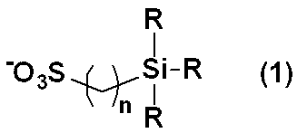
- an additive for an electrolytic solution comprising a compound comprising a silicon-containing sulfonate anion represented by the formula (1) and a monovalent or polyvalent cation, (In the formula, R independently represents an alkyl group having 1 to 8 carbon atoms, and n represents an integer of 2 to 6). 2. 1 an additive for an electrolytic solution in which R is all methyl groups, 3. 1 or 2 additive for electrolyte solution, wherein the cation is at least one monovalent cation selected from alkali metal ions, quaternary ammonium ions, imidazolium ions and quaternary phosphonium ions, 4).
- the alkali metal ion is a sodium ion; 5.
- the quaternary ammonium ion is an additive for an electrolyte solution of 3 represented by the formula (2): (In the formula, R 1 represents an alkyl group having 1 to 3 carbon atoms, R 2 represents a methyl group or an ethyl group, and m represents an integer of 1 or 2.) 6).
- the imidazolium ion is an additive for an electrolyte solution represented by formula (3): (In the formula, R 3 and R 4 each independently represents an alkyl group having 1 to 8 carbon atoms.) 7).
- the quaternary phosphonium ion is an additive for an electrolyte solution of 3 represented by the formula (4): (In the formula, R 5 represents an alkyl group having 1 to 30 carbon atoms, and R 6 represents an alkyl group or alkoxy group having 1 to 30 carbon atoms.) 8).
- An electrolyte solution comprising any one of the additive for electrolyte solution of 1 to 7, an organic solvent, and an electrolyte salt; 9. 8 electrolyte solution in which the organic solvent is carbonates, 10. 9 electrolyte solution in which the carbonate is a mixed solvent, 11.
- a method for improving the withstand voltage of an electrolytic solution by adding any one of the additives for electrolytic solution 1 to 7 to an electrolytic solution containing a solvent and an electrolyte salt is provided.
- An electricity storage device configured to include an electrolytic solution containing this additive has an increased operating upper limit voltage, can be increased in voltage and capacity, and the degree of deterioration due to repeated charge and discharge is suppressed.
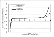
- FIG. 6 is a diagram showing the cyclic voltammetry measurement results (oxidation side) of Examples 1 to 6 and Comparative Example 1. It is a figure which shows the cyclic voltammetry measurement result of Example 7, 8 and the comparative example 2. FIG. It is a figure which shows the cyclic voltammetry measurement result of Example 9 and Comparative Example 3. It is a figure which shows the cyclic voltammetry measurement result of Example 10 and Comparative Example 4.
- the electrolytic solution additive according to the present invention comprises a compound composed of a silicon-containing sulfonate anion represented by the formula (1) and a monovalent or polyvalent cation.
- R each independently represents an alkyl group having 1 to 8 carbon atoms.
- the alkyl group having 1 to 8 carbon atoms may be linear, branched or cyclic.
- methyl, ethyl, n-propyl, i-propyl, c-propyl, n-butyl, i-butyl, s- Examples include butyl, t-butyl, c-butyl, n-pentyl, c-pentyl, n-hexyl, c-hexyl, n-heptyl, n-octyl and 2-ethylhexyl groups.
- R is preferably an alkyl group having 1 to 4 carbon atoms, more preferably an alkyl group having 1 to 3 carbon atoms, and most preferably a methyl group.
- n represents an integer of 2 to 6, preferably 2 or 3, and more preferably 3, from the viewpoint of further improving the withstand voltage of the electrolytic solution.
- the paired cations are not particularly limited and can be appropriately selected from known various cations.
- the valence is not particularly limited and may be a monovalent cation or a divalent or higher polyvalent cation.
- a monovalent cation is preferred.
- Specific examples thereof include alkali metal ions such as lithium, sodium, potassium, rubidium, and cesium, quaternary ammonium ions, quaternary phosphonium ions, imidazolium ions, and pyridinium ions. Ions, quaternary phosphonium ions, and imidazolium ions are preferred. From the viewpoint of improving flame retardancy, a phosphorus cation such as a quaternary phosphonium ion is preferred.
- Sodium is preferred as the alkali metal ion.
- the quaternary ammonium ion include a tetraalkylammonium ion and a tetraalkylammonium ion having an alkoxy group-substituted alkyl group.
- a pyrrolidinium ion having an alkyl group and an alkoxy-substituted alkyl group on a nitrogen atom is preferred, and a pyrrolidinium ion represented by the formula (2) is more preferred.
- R 1 represents an alkyl group having 1 to 3 carbon atoms
- R 2 represents a methyl group or an ethyl group
- m represents an integer of 1 or 2.
- the alkyl group having 1 to 3 carbon atoms include a methyl group, an ethyl group, and an n-propyl group, and a methyl group is particularly preferable.
- Examples of the imidazolium ion include a 1-alkyl-3-alkylimidazolium ion, and the imidazolium ion represented by the formula (3) is preferable in the present invention.
- R 3 and R 4 each independently represents an alkyl group having 1 to 8 carbon atoms, preferably an alkyl group having 1 to 4 carbon atoms, and more preferably a methyl or ethyl group. Examples of the alkyl group having 1 to 8 carbon atoms are the same as those described above.
- Examples of the quaternary phosphonium ion include a tetraalkylphosphonium ion and a trialkylalkoxyphosphonium ion.
- a phosphonium ion represented by the formula (4) is preferable.
- R 5 represents an alkyl group having 1 to 30 carbon atoms
- R 6 represents an alkyl group or alkoxy group having 1 to 30 carbon atoms.
- the alkyl group having 1 to 30 carbon atoms may be linear, branched or cyclic.
- Examples thereof include n-dodecyl, n-tridecyl, n-tetradecyl, n-pentadecyl, n-hexadecyl, n-heptadecyl, n-octadecyl, n-nonadecyl, n-eicosyl group and the like.
- the alkyl group therein may be linear, branched or cyclic.
- R 5 is preferably a linear alkyl group having 2 to 8 carbon atoms, more preferably a linear alkyl group having 2 to 5 carbon atoms, and even more preferably a linear alkyl group having 2 to 4 carbon atoms. N-Butyl group is most suitable.
- R 6 is preferably a linear alkyl group having 10 to 20 carbon atoms, and more preferably a linear alkyl group having 12 to 20 carbon atoms.
- the above-mentioned compounds composed of various silicon-containing sulfonate anions and monovalent cations can be synthesized by known methods, and some of them can be obtained as commercial products.
- sodium 3- (trimethylsilyl) -1-propanesulfonate is commercially available from Tokyo Chemical Industry Co., Ltd. and Aldrich.
- Specific examples of the synthesis method include a trialkylsilyl group-containing alkyl sulfonate and a halide salt of a desired cation (for example, tetraalkylphosphonium halide, tetraalkylammonium halide, 1,3-dialkylimidazolium halide, etc.
- a trialkylsilyl group-containing alkyl sulfonate and the above halide salt using a cation exchange resin and an anion exchange resin, respectively, and containing a trialkylsilyl group It can obtain by the neutralization method which mixes both, after converting into alkylsulfonic acid and the hydroxide of a desired cation.
- sodium salt, potassium salt, silver salt and the like can be used as the sulfonate.
- examples of the halogen atom include fluorine, chlorine, bromine and iodine atoms, with a chlorine atom and bromine atom being preferred.
- the solvent either water or an organic solvent may be used.
- the additive for electrolytic solution of the present invention is used by adding to an electrolytic solution containing a solvent and an electrolyte salt.
- the solvent can be appropriately selected from various solvents conventionally used as solvents for electrolytic solutions. Specific examples thereof include water; alcohols such as methanol and ethanol; dibutyl ether, 1,2- Dimethoxyethane, 1,2-ethoxymethoxyethane, methyl diglyme, methyl triglyme, methyl tetraglyme, ethyl glyme, ethyl diglyme, butyl diglyme, ethyl cellosolve, ethyl carbitol, butyl cellosolve, butyl carbitol, etc.
- the electrolyte salt is appropriately selected according to the type of the electricity storage device.
- Specific examples thereof include lithium tetrafluoroborate, lithium hexafluorophosphate, lithium bis (trifluoromethanesulfonyl) amide, lithium bis (fluoro Sulfonyl) amide, lithium perchlorate, lithium acetate, lithium trifluoroacetate, lithium benzoate, lithium p-toluenesulfonate, lithium nitrate, lithium bromide, lithium iodide, and the like; tetramethylammonium hexafluorophosphate, Tetraethylammonium hexafluorophosphate, tetrapropylammonium hexafluorophosphate, methyltriethylammonium hexafluorophosphate, tetraethylammonium tetraphosphate Oroboreto, quaternary ammonium salts such as
- the concentration of the electrolyte salt in the electrolytic solution is not particularly limited and is usually about 0.5 to 3 mol / L, preferably about 0.8 to 2 mol / L, preferably 0.9 to 1.5 mol / L. About L is more preferable.
- the addition amount of the additive for electrolyte solution of the present invention in the electrolyte solution is not particularly limited as long as the withstand voltage improvement effect is exhibited, but considering that the withstand voltage improvement effect is efficiently exhibited, In the whole electrolyte solution (100% by mass), 0.05% by mass or more is preferable, 0.1% by mass or more is more preferable, 0.5% by mass or more is further more preferable, and 0.7% by mass or more is further preferable. . Further, the upper limit is not particularly limited, but considering the suppression of the increase in the internal resistance of the device, 10% by mass is preferable, 8% by mass is more preferable, and 6% by mass is even more preferable.
- the power storage device in the present invention is not particularly limited, and various power storages such as an electric double layer capacitor, a lithium ion capacitor, a redox capacitor, a lithium secondary battery, a lithium ion secondary battery, a lithium air battery, and a proton polymer battery.
- the electricity storage device of the present invention is not particularly limited as long as it includes an electrolyte solution containing the above-described additive for electrolyte solution.
- the cathode current collector and the cathode active material layer formed on the surface thereof A general secondary battery, a positive electrode (air electrode) layer, a negative electrode current collector and a negative electrode having a negative electrode active material layer formed on the surface thereof, and a separator interposed between these electrodes
- An air battery having an electrolyte solution layer disposed between the electrodes, a negative electrode layer, and an electrode layer, to which an electrolyte solution containing the electrolyte solution additive of the present invention is applied, or a pair of polarizable electrodes,
- an electric double layer capacitor configured to include a separator interposed between and an electrolytic solution, an electrolytic solution including the electrolytic solution additive of the present invention is applied.
- Each material constituting the secondary battery may be appropriately selected from conventionally known materials and is not particularly limited, but an example thereof is as follows.
- Specific examples of the positive electrode current collector include an aluminum foil, an aluminum alloy foil, and the like.
- a three-dimensional porous body such as a foam or a nonwoven fabric can be used as the current collector.
- Specific examples of the positive electrode active material include a carbonaceous material such as activated carbon and carbon nanotube, which can reversibly carry lithium, an olivine type crystal structure, a layered rock salt type crystal structure, or a spinel type crystal structure. A lithium oxide etc. are mentioned.
- Examples of the activated carbon raw material include palm, phenol resin, petroleum coke and the like, and examples of the activated carbon raw material activation method include a steam activation method and a molten alkali activation method.
- the lithium oxide a composite oxide represented by the general formula LiMPO 4 (M is one or more of Fe (II), Mn (II), Co (II), Ni (II)), lithium cobaltate (LiCoO 2 ), NiCo series such as LiNiO 2 , LiMnO 2 , Li 2 MnO 3 , LiNi 0.8 Co 0.2 O 2 and the like.
- the negative electrode current collector include copper foil, copper alloy foil, nickel foil, nickel alloy foil, stainless steel foil, aluminum foil, and aluminum alloy foil.
- Specific examples of the negative electrode active material are not particularly limited as long as the material can occlude / release lithium ions, but carbonaceous materials (graphite, etc.), silicon oxide, silicon alloy, tin oxide, tin alloy, lithium Examples of the metal that can form a simple substance or a lithium alloy, such as aluminum, lead, tin, indium, bismuth, silver, barium, calcium, mercury, palladium, platinum, tellurium, zinc, and lanthanum. These may be used individually by 1 type and may be used in combination of 2 or more types.
- a carbonaceous material or a lithium composite oxide is preferable from the viewpoint of safety. Further, Ti (titanium), Li (lithium), or one containing both Ti and Li (for example, lithium titanate) is preferable from the viewpoint of high current density charge / discharge characteristics.
- the positive electrode active material and the negative electrode active material may be used together with a conductive material.
- a conductive material include carbon black, ketjen black, acetylene black, carbon whisker, carbon fiber, natural graphite, artificial graphite, titanium oxide, ruthenium oxide, aluminum, nickel and the like.
- the active material described above, the binder polymer, and, if necessary, an electrode slurry containing a conductive material and a solvent are applied onto a current collector, and dried under heating as necessary. Can be formed.
- the binder polymer can be appropriately selected from known materials and used, for example, polyvinylidene fluoride (PVdF), polyvinylpyrrolidone, polytetrafluoroethylene, tetrafluoroethylene-hexafluoropropylene copolymer, vinylidene fluoride- Hexafluoropropylene copolymer [P (VDF-HFP)], vinylidene fluoride-trichloroethylene copolymer [P (VDF-CTFE)], polyvinyl alcohol, ethylene-propylene-diene terpolymer, Examples thereof include styrene-butadiene rubber and carboxymethyl cellulose (CMC).
- the solvent is selected according to the type of binder polymer, but generally N-methyl-2-pyrrolidone or water is used. In addition, you may press the electrode in which the active material layer was formed as needed.
- separator examples include polyolefin separators such as polyethylene and polypropylene, polyester separators such as polyethylene terephthalate, polyamide separators, polyimide separators, cellulose separators, and glass fiber separators.
- each material constituting the electric double layer capacitor may be appropriately selected from conventionally known materials and is not particularly limited, but an example thereof is as follows.
- a general polarizable electrode an electrode obtained by applying a composition containing a carbonaceous material, a binder polymer and, if necessary, a conductive material on a current collector can be mentioned.
- the carbonaceous material is not particularly limited, and various conventionally known carbonaceous materials are exemplified, and examples thereof include activated carbon, graphite, graphene, carbon nanotube, carbon nanofiber, and carbon nanohorn.
- Specific examples of the positive electrode current collector include an aluminum foil and an aluminum alloy foil.
- Specific examples of the negative electrode current collector include copper foil, copper alloy foil, nickel foil, nickel alloy foil, and stainless steel foil.
- examples of the binder polymer and the conductive material include those exemplified for the secondary battery.
- a solvent may be used when preparing the composition. This solvent is selected according to the type of the binder polymer. In this case, N-methyl-2-pyrrolidone and water are also suitable.
- Specific examples of the separator include the same separators as exemplified in the secondary battery.
- the power storage device of the present invention is, for example, a device structure formed by interposing a separator between a pair of electrodes, stacked, folded, or wound, and formed into a coin shape or the like as necessary.
- a battery container such as a laminate pack
- an electrolytic solution containing the additive for electrolytic solution of the present invention If it is a battery can, it can be sealed, while if it is a laminate pack, heat sealing (thermal welding). Can be obtained.
- Electrochemical measuring device HSV-100 Constant temperature and temperature chamber ESPEC Corporation SU-241 Measurement conditions: Measurement was performed in a dry environment at a temperature of 25 ° C., using a glassy carbon electrode as a working electrode, a platinum electrode as a counter electrode, and an Ag / Ag + type or Ag / AgCl electrode as a reference electrode at a sweep rate of 5 mV / sec. .
- Internal resistance device Resistance meter RM3548 manufactured by Hioki Electric Co., Ltd.
- Compound 4 was obtained as a colorless transparent liquid in the same manner as in Synthesis Example 1 except that tributylhexadecylphosphonium bromide (manufactured by Tokyo Chemical Industry Co., Ltd.) was used instead of tributyldodecylphosphonium bromide (yield 1.68 g, yield) 62%).
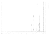
- the 1 H-NMR spectrum (solvent: deuterated chloroform) of Compound 4 is shown in FIG.
- the filtrate was passed through a column filled with 150 mL of DS-2 (eluent: ion-exchanged water), the filtrate in the range showing alkalinity was collected, and ethylmethylimidazolium hydroxide in which the chloride was completely replaced with hydroxide was collected. A side aqueous solution was obtained.
- DS-2 ion-exchanged water
- Cation exchange resin washed with ion-exchanged water (Amberlyst 15JS-HG ⁇ DRY, manufactured by Organo Corp.) 25 mL (volume with ion-exchanged water added, the same shall apply hereinafter) 3- (trimethylsilyl) -1 -A 65 mL aqueous solution of 4.0 g of sodium propanesulfonate (manufactured by Tokyo Chemical Industry Co., Ltd., hereinafter abbreviated as DSSNa) was added and left for several hours. After 15JS-HG ⁇ DRY was filtered off, the filtrate was added to 25 mL of freshly prepared 15JS-HG ⁇ DRY. After standing for several hours, 15JS-HG ⁇ DRY was filtered off.
- DSSNa sodium propanesulfonate
- Example 2 to 6 An electrolyte solution was prepared in the same manner as in Example 1 except that each of compounds 2 to 6 was used instead of compound 1.
- Ethylmethylimidazolium tetrafluoroborate (manufactured by Kishida Chemical Co., Ltd., hereinafter abbreviated as EMIBF4) is dissolved in propylene carbonate to prepare a 1M solution. In this solution, compound 7 is adjusted to a concentration of 5% by mass. To prepare an electrolytic solution.
- Example 8 An electrolyte solution was prepared in the same manner as in Example 7 except that Compound 1 was used instead of Compound 7.
- Example 9 Compound 8 was dissolved in methanol (manufactured by Kanto Chemical Co., Inc.) to prepare a 1M solution, and DSSNa was added to this solution to a concentration of 5% by mass to prepare an electrolytic solution.
- Example 10 Compound 1 was added to an LBG electrolyte solution (1 M LiPF 6 / EC: PC (1: 1) v / v%, manufactured by Kishida Chemical Co., Ltd.) to a concentration of 1% by mass to prepare an electrolyte solution.
- LBG electrolyte solution (1 M LiPF 6 / EC: PC (1: 1) v / v%, manufactured by Kishida Chemical Co., Ltd.
- the electrolytic solution prepared by adding the additive for electrolytic solution of the present invention has improved withstand voltage compared to the electrolytic solution to which the additive is not added.
- Lithium ion capacitor (1) Production of positive electrode structure Activated carbon maxsorb MSP20 (manufactured by Kansai Thermal Chemical Co., Ltd.) and conductive agent (HS-100, Electrochemical Industry) Co., Ltd.) and PVDF (manufactured by Aldrich, weight average molecular weight Mw: 534,000) as a coating solvent so as to have a mass composition of 85: 8: 7. -Pyrrolidone (hereinafter referred to as NMP) was mixed to prepare a positive electrode coating solution.
- NMP -Pyrrolidone
- the obtained coating solution was applied to etched aluminum foil (30CB) in the same manner as the positive electrode structure, and then rolled with a roll press, and NMP was removed by drying to form a negative electrode.
- An electrode structure was obtained.
- (3) Preparation of secondary battery Aluminum electrode lead-out terminals were spot welded to the positive electrode structure and negative electrode structure obtained above, respectively, and separators (TF40-35, Nippon Advanced Paper) The cell was assembled via Kogyo Co., Ltd. and inserted into an outer container made of aluminum laminate (Dai Nippon Printing Co., Ltd.). Into this, after injecting a predetermined amount of the electrolytic solution prepared in Example 10, it was allowed to stand for 12 hours or more at 25 ° C. under a reduced pressure of 10 kPa or less, impregnated with the electrolytic solution, and then sealed by thermal welding. A secondary battery cell was obtained.
- Lithium Ion Capacitor A secondary battery cell was fabricated in the same manner as in Example 11 except that the LBG electrolyte was used as it was instead of the electrolyte prepared in Example 10.
- Example 11 Using the secondary battery cells obtained in Example 11 and Comparative Example 5, a charge / discharge test was performed at an environmental temperature of 70 ° C. After reaching the charging upper limit voltage of 2.8 V, the battery was maintained for 1000 hours, and then discharged to 1.8 V, and the cell capacity and internal resistance at room temperature were measured to evaluate the degree of cell deterioration. The measurement results are shown in Table 1.
- Example 12 Electric double layer capacitor (1) Production of positive electrode structure Activated carbon maxsorb MSP20 (manufactured by Kansai Thermochemical Co., Ltd.), conductive agent (HS-100, manufactured by Denki Kagaku Kogyo Co., Ltd.) And a positive polarizable electrode obtained by mixing PVDF (manufactured by Aldrich, weight average molecular weight Mw: 534,000) as a binder in NMP as a coating solvent so as to have a mass composition of 85: 8: 7. A coating solution was prepared.
- Example 12 Using the electric double layer capacitor cell obtained in Example 12 and Comparative Example 6, a charge / discharge cycle test was conducted at 70 ° C. In the charge / discharge cycle test, the voltage was 2.25 V to 3.75 V, and continuous charge / discharge was performed at a current value of 200 A for 8 hours. After the cycle test, the cell capacity and internal resistance at room temperature were measured to evaluate the degree of cell deterioration. The measurement results are shown in Table 2.
- the device using the electrolytic solution to which the additive for electrolytic solution of the present invention is added is superior in capacity retention rate, has a low resistance increase rate, and has a degree of cell deterioration. I understand that it is small.
- Lithium ion battery (1) Production of positive electrode A positive electrode active material (LiCoO 2 , manufactured by Honjo Chemical Co., Ltd.), a conductive agent (acetylene black, manufactured by Electrochemical Industry Co., Ltd.), and PVDF A solution prepared by adjusting to a mass composition of 91: 3: 6 and dissolved therein was mixed with NMP to prepare a paste-like positive electrode coating solution. This positive electrode coating solution was applied onto an aluminum foil with a doctor blade so as to have a dry film thickness of 115 ⁇ m, dried at 80 ° C. for 2 hours, rolled to form a LiCoO 2 positive electrode, and a positive electrode structure was formed. Obtained.
- a positive electrode active material LiCoO 2 , manufactured by Honjo Chemical Co., Ltd.
- a conductive agent acetylene black, manufactured by Electrochemical Industry Co., Ltd.
- Example 14 Air battery (1) Preparation of positive electrode A positive electrode active material (MCMB, manufactured by Osaka Gas Chemical Co., Ltd.) and PVDF were adjusted to have a mass composition of 88:12, and an appropriate amount of NMP was mixed. A paste-like positive electrode coating solution was prepared. This positive electrode coating solution was applied onto an aluminum foil with a doctor blade so as to have a dry film thickness of 75 ⁇ m, and then dried at 140 ° C. for 72 hours to remove NMP and moisture. After being cut and rolled, it was peeled off from the current collector. The obtained positive electrode and 60 mesh (manufactured by Niraco) made of stainless steel SUS304 were pressure bonded and vacuum dried at 120 ° C. for 24 hours to obtain a positive electrode structure.
- MCMB manufactured by Osaka Gas Chemical Co., Ltd.
- the positive electrode structure obtained above and the metal lithium foil as the negative electrode were cut into sizes of 15 ⁇ and 13 ⁇ , respectively.
- the electrolyte solution prepared in Example 10 was impregnated into a polyolefin flat membrane (Hypore, manufactured by Asahi Kasei E-Materials Co., Ltd.) as a separator, and was sandwiched between the positive and negative electrodes previously cut to produce a lithium-air battery cell. did.
- the cell was placed in a positive electrode can in which air holes were formed so that the positive electrode current collector was opposed to the air holes, and then the negative electrode can was covered, and these were sealed to produce an air battery.
- the obtained cell was accommodated in a glass desiccator (500 mL) with a gas replacement cock.
- oxygen can be introduced and oxygen can be supplied to the positive electrode.
- the charging / discharging test was done. Charging voltage was set to 4.6 V and discharge end voltage was set to 2 V, and charging / discharging was performed at a current value of 0.02 mA.
- the obtained discharge capacity was 8.4 mAh, and the discharge capacity was almost the same even when the same charge / discharge cycle was repeated 10 times or more.
Abstract
Description
これらの蓄電デバイスでは、一般に、非プロトン性の有機溶媒に、イオン導電性塩を溶解させた溶液が電解液として使用されている。 In recent years, the spread of portable electronic devices such as digital cameras, smartphones, and tablet devices has been remarkable, and accordingly, the demand for power storage devices such as secondary batteries that can be used repeatedly by charging and used as the power source of these devices has greatly increased. At the same time, there is a growing demand for higher capacity and higher energy density.
In these power storage devices, generally, a solution in which an ion conductive salt is dissolved in an aprotic organic solvent is used as an electrolytic solution.
この電解液の耐電圧を向上する技術として、電解液中に各種添加剤を加える手法が報告されている(例えば、特許文献1~4参照)が、耐電圧向上効果や内部抵抗上昇抑制という点でさらなる改良の余地がある。
また、イオン液体は耐電圧が高いことが知られているものの、一般的な有機溶媒と比較して低温から常温域でのイオン導電性という点で問題があり、低温で高電圧作動するデバイスには不向きである。 By the way, in an electricity storage device aiming at high voltage operation, the withstand voltage of the electrolyte is a factor that determines the upper limit potential of the device. However, under a high voltage, the organic solvent or ion conductive salt constituting the electrolyte is exposed to a high voltage. Therefore, there is a case where the electrode surface is electrically decomposed, and an electrolytic solution having more excellent withstand voltage is required.
As a technique for improving the withstand voltage of the electrolytic solution, a method of adding various additives to the electrolytic solution has been reported (for example, see
In addition, although ionic liquids are known to have a high withstand voltage, there are problems in terms of ionic conductivity from low temperatures to normal temperatures compared to common organic solvents, and devices that operate at high voltages at low temperatures. Is unsuitable.
1. 式(1)で示されるケイ素含有スルホン酸アニオンと一価または多価のカチオンとから構成される化合物からなる電解液用添加剤、

2. 前記Rが、全てメチル基である1の電解液用添加剤、
3. 前記カチオンが、アルカリ金属イオン、4級アンモニウムイオン、イミダゾリウムイオンおよび4級ホスホニウムイオンから選ばれる少なくとも1種の一価のカチオンである1または2の電解液用添加剤、
4. 前記アルカリ金属イオンが、ナトリウムイオンである3の電解液用添加剤、
5. 前記4級アンモニウムイオンが、式(2)で示される3の電解液用添加剤、

6. 前記イミダゾリウムイオンが、式(3)で示される3の電解液用添加剤、

7. 前記4級ホスホニウムイオンが、式(4)で示される3の電解液用添加剤、

8. 1~7のいずれかの電解液用添加剤と、有機溶媒と、電解質塩とを含む電解液、
9. 前記有機溶媒が、カーボネート類である8の電解液、
10. 前記カーボネート類が、混合溶媒である9の電解液、
11. 8~10のいずれかの電解液を用いて構成される蓄電デバイス、
12. 1~7のいずれかの電解液用添加剤を用いて構成される蓄電デバイス、
13. 二次電池または電気二重層キャパシタである11または12の蓄電デバイス、
14. 1~7のいずれかの電解液用添加剤を、溶媒および電解質塩を含む電解液に加え、電解液の耐電圧を向上させる方法
を提供する。 That is, the present invention
1. An additive for an electrolytic solution comprising a compound comprising a silicon-containing sulfonate anion represented by the formula (1) and a monovalent or polyvalent cation,
2. 1 an additive for an electrolytic solution in which R is all methyl groups,
3. 1 or 2 additive for electrolyte solution, wherein the cation is at least one monovalent cation selected from alkali metal ions, quaternary ammonium ions, imidazolium ions and quaternary phosphonium ions,
4). 3 an additive for an electrolytic solution, wherein the alkali metal ion is a sodium ion;
5. The quaternary ammonium ion is an additive for an electrolyte solution of 3 represented by the formula (2):
6). The imidazolium ion is an additive for an electrolyte solution represented by formula (3):
7). The quaternary phosphonium ion is an additive for an electrolyte solution of 3 represented by the formula (4):
8). An electrolyte solution comprising any one of the additive for electrolyte solution of 1 to 7, an organic solvent, and an electrolyte salt;
9. 8 electrolyte solution in which the organic solvent is carbonates,
10. 9 electrolyte solution in which the carbonate is a mixed solvent,
11. An electricity storage device configured using any one of 8 to 10 electrolytic solution,
12 An electricity storage device configured using any one of the electrolyte additives of 1 to 7,
13. 11 or 12 electricity storage devices that are secondary batteries or electric double layer capacitors,
14 A method for improving the withstand voltage of an electrolytic solution by adding any one of the additives for
この添加剤を含む電解液を備えて構成された蓄電デバイスは、作動上限電圧が上昇し、高電圧化、高容量密度化が図れるとともに、繰り返し充放電に伴う劣化度合いが抑制される。 By adding a compound composed of a silicon-containing sulfonate anion and a monovalent cation according to the present invention to an existing electrolytic solution, the withstand voltage of the electrolytic solution can be improved.
An electricity storage device configured to include an electrolytic solution containing this additive has an increased operating upper limit voltage, can be increased in voltage and capacity, and the degree of deterioration due to repeated charge and discharge is suppressed.
本発明に係る電解液用添加剤は、式(1)で示されるケイ素含有スルホン酸アニオンと一価または多価のカチオンとから構成される化合物からなる。 Hereinafter, the present invention will be described in more detail.
The electrolytic solution additive according to the present invention comprises a compound composed of a silicon-containing sulfonate anion represented by the formula (1) and a monovalent or polyvalent cation.
炭素数1~8のアルキル基としては、直鎖、分岐、環状のいずれでもよく、例えば、メチル、エチル、n-プロピル、i-プロピル、c-プロピル、n-ブチル、i-ブチル、s-ブチル、t-ブチル、c-ブチル、n-ペンチル、c-ペンチル、n-ヘキシル、c-ヘキシル、n-ヘプチル、n-オクチル、2-エチルヘキシル基等が挙げられる。
中でも、Rとしては、炭素数1~4のアルキル基が好ましく、炭素数1~3のアルキル基がより好ましく、メチル基が最適である。
nは、2~6の整数を表すが、電解液の耐電圧をより向上させるという点から、2または3が好ましく、3がより好ましい。 In the formula (1), R each independently represents an alkyl group having 1 to 8 carbon atoms.
The alkyl group having 1 to 8 carbon atoms may be linear, branched or cyclic. For example, methyl, ethyl, n-propyl, i-propyl, c-propyl, n-butyl, i-butyl, s- Examples include butyl, t-butyl, c-butyl, n-pentyl, c-pentyl, n-hexyl, c-hexyl, n-heptyl, n-octyl and 2-ethylhexyl groups.
Among them, R is preferably an alkyl group having 1 to 4 carbon atoms, more preferably an alkyl group having 1 to 3 carbon atoms, and most preferably a methyl group.
n represents an integer of 2 to 6, preferably 2 or 3, and more preferably 3, from the viewpoint of further improving the withstand voltage of the electrolytic solution.
その具体例としては、リチウム、ナトリウム、カリウム、ルビジウム、セシウム等のアルカリ金属イオン、4級アンモニウムイオン、4級ホスホニウムイオン、イミダゾリウムイオン、ピリジニウムイオンなどが挙げられるが、アルカリ金属イオン、4級アンモニウムイオン、4級ホスホニウムイオン、イミダゾリウムイオンが好ましい。
なお、難燃性を向上させるという点から、4級ホスホニウムイオン等のリン系のカチオンが好適である。 Since the additive for electrolyte solution of the present invention is characterized by having the above-mentioned anions, the paired cations are not particularly limited and can be appropriately selected from known various cations. . The valence is not particularly limited and may be a monovalent cation or a divalent or higher polyvalent cation. In the present invention, a monovalent cation is preferred.
Specific examples thereof include alkali metal ions such as lithium, sodium, potassium, rubidium, and cesium, quaternary ammonium ions, quaternary phosphonium ions, imidazolium ions, and pyridinium ions. Ions, quaternary phosphonium ions, and imidazolium ions are preferred.
From the viewpoint of improving flame retardancy, a phosphorus cation such as a quaternary phosphonium ion is preferred.
4級アンモニウムイオンとしては、テトラアルキルアンモニウムイオン、アルコキシ基置換アルキル基を有するテトラアルキルアンモニウムイオン等が挙げられるが、本発明では、窒素原子上に、アルキル基およびアルコキシ置換アルキル基を有するピロリジニウムイオンが好ましく、式(2)で示されるピロリジニウムイオンがより好ましい。 Sodium is preferred as the alkali metal ion.
Examples of the quaternary ammonium ion include a tetraalkylammonium ion and a tetraalkylammonium ion having an alkoxy group-substituted alkyl group. In the present invention, a pyrrolidinium ion having an alkyl group and an alkoxy-substituted alkyl group on a nitrogen atom. Is preferred, and a pyrrolidinium ion represented by the formula (2) is more preferred.

炭素数1~3のアルキル基としては、メチル、エチル、n-プロピル基等が挙げられるが、特に、メチル基が好ましい。 In formula (2), R 1 represents an alkyl group having 1 to 3 carbon atoms, R 2 represents a methyl group or an ethyl group, and m represents an integer of 1 or 2.
Examples of the alkyl group having 1 to 3 carbon atoms include a methyl group, an ethyl group, and an n-propyl group, and a methyl group is particularly preferable.

炭素数1~8のアルキル基としては、上記と同様のものが挙げられる。 In formula (3), R 3 and R 4 each independently represents an alkyl group having 1 to 8 carbon atoms, preferably an alkyl group having 1 to 4 carbon atoms, and more preferably a methyl or ethyl group.
Examples of the alkyl group having 1 to 8 carbon atoms are the same as those described above.

炭素数1~30のアルキル基としては、直鎖、分岐、環状のいずれでもよく、例えば、メチル、エチル、n-プロピル、i-プロピル、c-プロピル、n-ブチル、i-ブチル、s-ブチル、t-ブチル、c-ブチル、n-ペンチル、c-ペンチル、n-ヘキシル、c-ヘキシル、n-ヘプチル、n-オクチル、2-エチルヘキシル、n-ノニル、n-デシル、n-ウンデシル、n-ドデシル、n-トリデシル、n-テトラデシル、n-ペンタデシル、n-ヘキサデシル、n-ヘプタデシル、n-オクタデシル、n-ノナデシル、n-エイコシル基等が挙げられる。 In formula (4), R 5 represents an alkyl group having 1 to 30 carbon atoms, and R 6 represents an alkyl group or alkoxy group having 1 to 30 carbon atoms.
The alkyl group having 1 to 30 carbon atoms may be linear, branched or cyclic. For example, methyl, ethyl, n-propyl, i-propyl, c-propyl, n-butyl, i-butyl, s- Butyl, t-butyl, c-butyl, n-pentyl, c-pentyl, n-hexyl, c-hexyl, n-heptyl, n-octyl, 2-ethylhexyl, n-nonyl, n-decyl, n-undecyl, Examples thereof include n-dodecyl, n-tridecyl, n-tetradecyl, n-pentadecyl, n-hexadecyl, n-heptadecyl, n-octadecyl, n-nonadecyl, n-eicosyl group and the like.
R6としては、炭素数10~20の直鎖アルキル基が好ましく、炭素数12~20の直鎖アルキル基がより好ましい。 Among these, R 5 is preferably a linear alkyl group having 2 to 8 carbon atoms, more preferably a linear alkyl group having 2 to 5 carbon atoms, and even more preferably a linear alkyl group having 2 to 4 carbon atoms. N-Butyl group is most suitable.
R 6 is preferably a linear alkyl group having 10 to 20 carbon atoms, and more preferably a linear alkyl group having 12 to 20 carbon atoms.
例えば、3-(トリメチルシリル)-1-プロパンスルホン酸ナトリウムは、東京化成工業(株)や、アルドリッチ社で市販されている。
また、その合成法の具体例としては、トリアルキルシリル基含有アルキルスルホン酸塩と、所望のカチオンのハライド塩(例えば、テトラアルキルホスホニウムハライド、テトラアルキルアンモニウムハライド、1,3-ジアルキルイミダゾリウムハライド等)とを、溶媒中で反応させて製造する方法や、トリアルキルシリル基含有アルキルスルホン酸塩と、上記ハライド塩を、各々陽イオン交換樹脂、陰イオン交換樹脂を用いて、トリアルキルシリル基含有アルキルスルホン酸および所望のカチオンの水酸化物に変換した後、両者を混合する中和法によって得ることができる。
この場合、スルホン酸塩としては、ナトリウム塩、カリウム塩、銀塩等を用いることができる。
また、ハロゲン原子としては、フッ素、塩素、臭素、ヨウ素原子が挙げられるが、塩素原子、臭素原子が好ましい。
溶媒としては、水、有機溶媒どちらでも構わない。 The above-mentioned compounds composed of various silicon-containing sulfonate anions and monovalent cations can be synthesized by known methods, and some of them can be obtained as commercial products.
For example, sodium 3- (trimethylsilyl) -1-propanesulfonate is commercially available from Tokyo Chemical Industry Co., Ltd. and Aldrich.
Specific examples of the synthesis method include a trialkylsilyl group-containing alkyl sulfonate and a halide salt of a desired cation (for example, tetraalkylphosphonium halide, tetraalkylammonium halide, 1,3-dialkylimidazolium halide, etc. ) And a trialkylsilyl group-containing alkyl sulfonate and the above halide salt using a cation exchange resin and an anion exchange resin, respectively, and containing a trialkylsilyl group It can obtain by the neutralization method which mixes both, after converting into alkylsulfonic acid and the hydroxide of a desired cation.
In this case, sodium salt, potassium salt, silver salt and the like can be used as the sulfonate.
In addition, examples of the halogen atom include fluorine, chlorine, bromine and iodine atoms, with a chlorine atom and bromine atom being preferred.
As the solvent, either water or an organic solvent may be used.
溶媒としては、従来、電解液用溶媒として用いられている各種溶媒から適宜選択して用いることができ、その具体例としては、水;メタノール、エタノール等のアルコール類;ジブチルエーテル、1,2-ジメトキシエタン、1,2-エトキシメトキシエタン、メチルジグライム、メチルトリグライム、メチルテトラグライム、エチルグライム、エチルジグライム、ブチルジグライム、エチルセルソルブ、エチルカルビトール、ブチルセルソルブ、ブチルカルビトール等の鎖状エーテル類;テトラヒドロフラン、2-メチルテトラヒドロフラン、1,3-ジオキソラン、4,4-ジメチル-1,3-ジオキサン等の複素環式エーテル類;γ-ブチロラクトン、γ-バレロラクトン、δ-バレロラクトン、3-メチル-1,3-オキサゾリジン-2-オン、3-エチル-1,3-オキサゾリジン-2-オン等のラクトン類;N-メチルホルムアミド、N,N-ジメチルホルムアミド、N-メチルアセトアミド、N-メチルピロリジノン等のアミド類;ジエチルカーボネート、ジメチルカーボネート、エチルメチルカーボネート、プロピレンカーボネート、エチレンカーボネート、ブチレンカーボネート等のカーボネート類;1,3-ジメチル-2-イミダゾリジノン等のイミダゾリン類;アセトニトリル、プロピオニトリル等のニトリル類などの有機溶媒が挙げられ、これらは単独で、または2種以上混合して用いることができる。
中でも、有機溶媒が好ましく、カーボネート類がより好ましく、2種以上のカーボネートの混合溶媒がより一層好ましい。 The additive for electrolytic solution of the present invention is used by adding to an electrolytic solution containing a solvent and an electrolyte salt.
The solvent can be appropriately selected from various solvents conventionally used as solvents for electrolytic solutions. Specific examples thereof include water; alcohols such as methanol and ethanol; dibutyl ether, 1,2- Dimethoxyethane, 1,2-ethoxymethoxyethane, methyl diglyme, methyl triglyme, methyl tetraglyme, ethyl glyme, ethyl diglyme, butyl diglyme, ethyl cellosolve, ethyl carbitol, butyl cellosolve, butyl carbitol, etc. Chain ethers of the following: heterocyclic ethers such as tetrahydrofuran, 2-methyltetrahydrofuran, 1,3-dioxolane, 4,4-dimethyl-1,3-dioxane; γ-butyrolactone, γ-valerolactone, δ-valero Lactone, 3-methyl-1,3-oxazolidine Lactones such as -one, 3-ethyl-1,3-oxazolidine-2-one; amides such as N-methylformamide, N, N-dimethylformamide, N-methylacetamide, N-methylpyrrolidinone; diethyl carbonate, Organic solvents such as dimethyl carbonate, ethyl methyl carbonate, propylene carbonate, ethylene carbonate, butylene carbonate and the like; imidazolines such as 1,3-dimethyl-2-imidazolidinone; nitriles such as acetonitrile and propionitrile These may be used alone or in combination of two or more.
Among these, an organic solvent is preferable, carbonates are more preferable, and a mixed solvent of two or more carbonates is still more preferable.
また、その上限は特に限定されるものではないが、デバイスの内部抵抗の上昇を抑制することを考慮すると、10質量%が好ましく、8質量%がより好ましく、6質量%がより一層好ましい。 The addition amount of the additive for electrolyte solution of the present invention in the electrolyte solution is not particularly limited as long as the withstand voltage improvement effect is exhibited, but considering that the withstand voltage improvement effect is efficiently exhibited, In the whole electrolyte solution (100% by mass), 0.05% by mass or more is preferable, 0.1% by mass or more is more preferable, 0.5% by mass or more is further more preferable, and 0.7% by mass or more is further preferable. .
Further, the upper limit is not particularly limited, but considering the suppression of the increase in the internal resistance of the device, 10% by mass is preferable, 8% by mass is more preferable, and 6% by mass is even more preferable.
本発明の蓄電デバイスは、上述した電解液用添加剤を含む電解液を備えるものであれば、特に限定されるものではなく、例えば、正極集電体およびその表面に形成された正極活物質層を有する正極と、負極集電体およびその表面に形成された負極活物質層を有する負極と、これら各極間に介在するセパレータとを備える一般的な二次電池や、正極(空気極)層と負極層、および各極間に配置された電解液層を有する空気電池において、本発明の電解液用添加剤を含む電解液を適用したもの、あるいは、一対の分極性電極と、これら電極間に介在するセパレータと、電解液とを備えて構成される電気二重層キャパシタにおいて、本発明の電解液用添加剤を含む電解液を適用したものなどが挙げられる。 The power storage device in the present invention is not particularly limited, and various power storages such as an electric double layer capacitor, a lithium ion capacitor, a redox capacitor, a lithium secondary battery, a lithium ion secondary battery, a lithium air battery, and a proton polymer battery. Device.
The electricity storage device of the present invention is not particularly limited as long as it includes an electrolyte solution containing the above-described additive for electrolyte solution. For example, the cathode current collector and the cathode active material layer formed on the surface thereof A general secondary battery, a positive electrode (air electrode) layer, a negative electrode current collector and a negative electrode having a negative electrode active material layer formed on the surface thereof, and a separator interposed between these electrodes An air battery having an electrolyte solution layer disposed between the electrodes, a negative electrode layer, and an electrode layer, to which an electrolyte solution containing the electrolyte solution additive of the present invention is applied, or a pair of polarizable electrodes, In an electric double layer capacitor configured to include a separator interposed between and an electrolytic solution, an electrolytic solution including the electrolytic solution additive of the present invention is applied.
正極集電体の具体例としては、アルミニウム箔、アルミニウム合金箔等が挙げられ、これらの発泡体や不織布状などの三次元多孔質体を集電体に用いることもできる。
正極活物質の具体例としては、リチウムを可逆的に担持可能である、活性炭、カーボンナノチューブ等の炭素質材料、オリビン型の結晶構造、層状岩塩型の結晶構造、またはスピネル型の結晶構造を有するリチウム酸化物等が挙げられる。活性炭原料としては、やしがら、フェノール樹脂、石油コークス等が挙げられ、また活性炭原料の賦活方法としては水蒸気賦活法、溶融アルカリ賦活法等が挙げられる。リチウム酸化物としては、一般式LiMPO4(Mは、Fe(II)、Mn(II)、Co(II)、Ni(II)の一以上)で表される複合酸化物、コバルト酸リチウム(LiCoO2)、LiNiO2、LiMnO2、Li2MnO3、LiNi0.8Co0.2O2等のNiCo系などが挙げられる。 Each material constituting the secondary battery may be appropriately selected from conventionally known materials and is not particularly limited, but an example thereof is as follows.
Specific examples of the positive electrode current collector include an aluminum foil, an aluminum alloy foil, and the like. A three-dimensional porous body such as a foam or a nonwoven fabric can be used as the current collector.
Specific examples of the positive electrode active material include a carbonaceous material such as activated carbon and carbon nanotube, which can reversibly carry lithium, an olivine type crystal structure, a layered rock salt type crystal structure, or a spinel type crystal structure. A lithium oxide etc. are mentioned. Examples of the activated carbon raw material include palm, phenol resin, petroleum coke and the like, and examples of the activated carbon raw material activation method include a steam activation method and a molten alkali activation method. As the lithium oxide, a composite oxide represented by the general formula LiMPO 4 (M is one or more of Fe (II), Mn (II), Co (II), Ni (II)), lithium cobaltate (LiCoO 2 ), NiCo series such as LiNiO 2 , LiMnO 2 , Li 2 MnO 3 , LiNi 0.8 Co 0.2 O 2 and the like.
負極活物質の具体例としては、リチウムイオンを吸蔵・放出可能な物質であれば特に制限はないが、炭素質材料(黒鉛等)、ケイ素酸化物、ケイ素合金、錫酸化物、錫合金、リチウム単体やリチウム合金を形成することができる金属、例えば、アルミニウム、鉛、錫、インジウム、ビスマス、銀、バリウム、カルシウム、水銀、パラジウム、白金、テルル、亜鉛、ランタン等が挙げられる。これらは1種を単独で用いてもよく、2種以上のものを組み合わせて用いてもよい。炭素質材料またはリチウム複合酸化物が安全性の観点から好ましい。さらにTi(チタン)、Li(リチウム)またはTiおよびLiの双方を含有するもの(例えば、チタン酸リチウム等)が、高電流密度充放電特性の観点で好ましい。 Specific examples of the negative electrode current collector include copper foil, copper alloy foil, nickel foil, nickel alloy foil, stainless steel foil, aluminum foil, and aluminum alloy foil.
Specific examples of the negative electrode active material are not particularly limited as long as the material can occlude / release lithium ions, but carbonaceous materials (graphite, etc.), silicon oxide, silicon alloy, tin oxide, tin alloy, lithium Examples of the metal that can form a simple substance or a lithium alloy, such as aluminum, lead, tin, indium, bismuth, silver, barium, calcium, mercury, palladium, platinum, tellurium, zinc, and lanthanum. These may be used individually by 1 type and may be used in combination of 2 or more types. A carbonaceous material or a lithium composite oxide is preferable from the viewpoint of safety. Further, Ti (titanium), Li (lithium), or one containing both Ti and Li (for example, lithium titanate) is preferable from the viewpoint of high current density charge / discharge characteristics.
導電材としては、カーボンブラック、ケッチェンブラック、アセチレンブラック、カーボンウイスカー、炭素繊維、天然黒鉛、人造黒鉛、酸化チタン、酸化ルテニウム、アルミニウム、ニッケル等が挙げられる。 The positive electrode active material and the negative electrode active material may be used together with a conductive material.
Examples of the conductive material include carbon black, ketjen black, acetylene black, carbon whisker, carbon fiber, natural graphite, artificial graphite, titanium oxide, ruthenium oxide, aluminum, nickel and the like.
バインダーポリマーとしては、公知の材料から適宜選択して用いることができ、例えば、ポリフッ化ビニリデン(PVdF)、ポリビニルピロリドン、ポリテトラフルオロエチレン、テトラフルオロエチレン-ヘキサフルオロプロピレン共重合体、フッ化ビニリデン-ヘキサフルオロプロピレン共重合体〔P(VDF-HFP)〕、フッ化ビニリデン-塩化3フッ化エチレン共重合体〔P(VDF-CTFE)〕、ポリビニルアルコール、エチレン-プロピレン-ジエン三元共重合体、スチレン-ブタジエンゴム、カルボキシメチルセルロース(CMC)等が挙げられる。
溶媒としては、バインダーポリマーの種類に応じて選定されるものであるが、一般的には、N-メチル-2-ピロリドンや水が用いられる。
なお、活物質層を形成した電極は、必要に応じてプレスしてもよい。 For the positive electrode and negative electrode active material layers, the active material described above, the binder polymer, and, if necessary, an electrode slurry containing a conductive material and a solvent are applied onto a current collector, and dried under heating as necessary. Can be formed.
The binder polymer can be appropriately selected from known materials and used, for example, polyvinylidene fluoride (PVdF), polyvinylpyrrolidone, polytetrafluoroethylene, tetrafluoroethylene-hexafluoropropylene copolymer, vinylidene fluoride- Hexafluoropropylene copolymer [P (VDF-HFP)], vinylidene fluoride-trichloroethylene copolymer [P (VDF-CTFE)], polyvinyl alcohol, ethylene-propylene-diene terpolymer, Examples thereof include styrene-butadiene rubber and carboxymethyl cellulose (CMC).
The solvent is selected according to the type of binder polymer, but generally N-methyl-2-pyrrolidone or water is used.
In addition, you may press the electrode in which the active material layer was formed as needed.
一般的な分極性電極としては、炭素質材料とバインダーポリマーと必要に応じて導電材を含む組成物を集電体上に塗布したものが挙げられる。
炭素質材料としては、特に限定されるものではなく、従来公知の種々の炭素質材料が挙げられ、例えば、活性炭、グラファイト、グラフェン、カーボンナノチューブ、カーボンナノファイバー、カーボンナノホーン等が挙げられる。
正極集電体の具体例としては、アルミニウム箔、アルミニウム合金箔等が挙げられる。
負極集電体の具体例としては、銅箔、銅合金箔、ニッケル箔、ニッケル合金箔、ステンレス箔等が挙げられる。
その他、バインダーポリマー、導電材としては、二次電池で例示したものと同様のものが挙げられる。
また、上記組成物の調製時には溶媒を用いてもよい。この溶媒は、バインダーポリマーの種類に応じて選定されるものであるが、この場合も、N-メチル-2-ピロリドンや水が好適である。
セパレータの具体例としても、二次電池で例示したものと同様のものが挙げられる。 Further, each material constituting the electric double layer capacitor may be appropriately selected from conventionally known materials and is not particularly limited, but an example thereof is as follows.
As a general polarizable electrode, an electrode obtained by applying a composition containing a carbonaceous material, a binder polymer and, if necessary, a conductive material on a current collector can be mentioned.
The carbonaceous material is not particularly limited, and various conventionally known carbonaceous materials are exemplified, and examples thereof include activated carbon, graphite, graphene, carbon nanotube, carbon nanofiber, and carbon nanohorn.
Specific examples of the positive electrode current collector include an aluminum foil and an aluminum alloy foil.
Specific examples of the negative electrode current collector include copper foil, copper alloy foil, nickel foil, nickel alloy foil, and stainless steel foil.
In addition, examples of the binder polymer and the conductive material include those exemplified for the secondary battery.
In addition, a solvent may be used when preparing the composition. This solvent is selected according to the type of the binder polymer. In this case, N-methyl-2-pyrrolidone and water are also suitable.
Specific examples of the separator include the same separators as exemplified in the secondary battery.
[1]1H-NMRスペクトル
装置:日本電子(株)製 AL-400
[2]サイクリックボルタンメトリー
装置:北斗電工(株)製 電気化学測定装置HSV-100
定温恒温槽:エスペック(株)SU-241
測定条件:ドライ環境下、温度25℃、作用極にグラッシーカーボン電極、対極に白金電極、参照極にAg/Ag+型またはAg/AgCl電極を用いて、掃引速度5mV/secで測定を行った。
[3]内部抵抗
装置:日置電気(株)製 抵抗計RM3548 EXAMPLES Hereinafter, although an Example and a comparative example are given and this invention is demonstrated more concretely, this invention is not limited to the following Example. The analyzers and conditions used are as follows.
[1] 1 H-NMR spectrum apparatus: AL-400 manufactured by JEOL Ltd.
[2] Cyclic voltammetry device: Hokuto Denko Co., Ltd. electrochemical measuring device HSV-100
Constant temperature and temperature chamber: ESPEC Corporation SU-241
Measurement conditions: Measurement was performed in a dry environment at a temperature of 25 ° C., using a glassy carbon electrode as a working electrode, a platinum electrode as a counter electrode, and an Ag / Ag + type or Ag / AgCl electrode as a reference electrode at a sweep rate of 5 mV / sec. .
[3] Internal resistance device: Resistance meter RM3548 manufactured by Hioki Electric Co., Ltd.
[合成例1]化合物3の合成


イオン交換水で洗浄済みの陽イオン交換樹脂(アンバーリスト15JS-HG・DRY、オルガノ(株)製)25mL(イオン交換水を加えた状態での容量、以下同様)に3-(トリメチルシリル)-1-プロパンスルホン酸ナトリウム(東京化成工業(株)製、以下DSSNaと略す)4.0gの65mL水溶液を加え、数時間放置した。15JS-HG・DRYをろ別後、ろ液を新たに用意した洗浄済みの15JS-HG・DRY 25mLに加えた。数時間放置後、15JS-HG・DRYをろ別した。次にろ液を15JS-HG・DRY 100mL(溶離液:イオン交換水)を充填したカラムに通し、酸性を示す範囲のろ液を集め、完全にナトリウムが水素に置換した3-(トリメチルシリル)-1-プロパンスルホン酸水溶液を得た。
得られたエチルメチルイミダゾリウムハイドロキサイド水溶液と3-(トリメチルシリル)-1-プロパンスルホン酸水溶液とを混合し、pHを6~8に調整し、この混合溶液から水を、初期はエバポレータ、その後、真空ポンプを用いて除去し、化合物7を白色固体として得た(収量5.3g,収率92%:DSSNa基準)。得られた化合物7の1H-NMRスペクトル(溶媒:重ジメチルスルホキシド)を図3に示す。 40 mL of an anion exchange resin (DS-2, manufactured by Organo Corporation) that has been washed with ion exchange water (volume with ion exchange water added, the same applies hereinafter) to ethyl methyl imidazolium chloride (Tokyo Chemical Industry ( 3.0 g of 15 mL aqueous solution was added and allowed to stand for several hours. After DS-2 was filtered off, the filtrate was added to 40 mL of freshly prepared washed DS-2. After standing for several hours, DS-2 was filtered off. Next, the filtrate was passed through a column filled with 150 mL of DS-2 (eluent: ion-exchanged water), the filtrate in the range showing alkalinity was collected, and ethylmethylimidazolium hydroxide in which the chloride was completely replaced with hydroxide was collected. A side aqueous solution was obtained.
Cation exchange resin washed with ion-exchanged water (Amberlyst 15JS-HG · DRY, manufactured by Organo Corp.) 25 mL (volume with ion-exchanged water added, the same shall apply hereinafter) 3- (trimethylsilyl) -1 -A 65 mL aqueous solution of 4.0 g of sodium propanesulfonate (manufactured by Tokyo Chemical Industry Co., Ltd., hereinafter abbreviated as DSSNa) was added and left for several hours. After 15JS-HG · DRY was filtered off, the filtrate was added to 25 mL of freshly prepared 15JS-HG · DRY. After standing for several hours, 15JS-HG · DRY was filtered off. Next, the filtrate was passed through a column packed with 100 mL of 15JS-HG · DRY (eluent: ion-exchanged water), and the filtrate in an acidic range was collected. 3- (Trimethylsilyl)-in which sodium was completely replaced with hydrogen A 1-propanesulfonic acid aqueous solution was obtained.
The obtained ethyl methyl imidazolium hydroxide aqueous solution and 3- (trimethylsilyl) -1-propanesulfonic acid aqueous solution were mixed to adjust the pH to 6-8, and water was initially added to the evaporator, then to the evaporator, And was removed using a vacuum pump to obtain
なお、化合物1,2は特開2013-014536号公報の実施例1,2に従ってそれぞれ合成し、化合物5,6は特開2014-080388号公報の実施例1,2に従ってそれぞれ合成し、化合物8は特開2007-161733号公報の合成例3に従って合成した。

[実施例1]
化合物8をプロピレンカーボネート(キシダ化学(株)製)に溶かして1Mの溶液を調製し、この溶液に、化合物1を1質量%の濃度となるように添加して電解液を調製した。 [2] Preparation of electrolytic solution [Example 1]
Compound 8 was dissolved in propylene carbonate (manufactured by Kishida Chemical Co., Ltd.) to prepare a 1M solution, and
化合物1のかわりに、化合物2~6をそれぞれ用いた以外は、実施例1と同様にして電解液を調製した。 [Examples 2 to 6]
An electrolyte solution was prepared in the same manner as in Example 1 except that each of
エチルメチルイミダゾリウムテトラフルオロボレート(キシダ化学(株)製、以下、EMIBF4と略す)を、プロピレンカーボネートに溶かして1Mの溶液を調製し、この溶液に、化合物7を5質量%の濃度になるように添加して電解液を調製した。 [Example 7]
Ethylmethylimidazolium tetrafluoroborate (manufactured by Kishida Chemical Co., Ltd., hereinafter abbreviated as EMIBF4) is dissolved in propylene carbonate to prepare a 1M solution. In this solution,
化合物7のかわりに、化合物1を用いた以外は、実施例7と同様にして電解液を調製した。 [Example 8]
An electrolyte solution was prepared in the same manner as in Example 7 except that
化合物8を、メタノール(関東化学(株)製)に溶かして1Mの溶液を調製し、この溶液に、DSSNaを5質量%の濃度になるように添加して電解液を調製した。 [Example 9]
Compound 8 was dissolved in methanol (manufactured by Kanto Chemical Co., Inc.) to prepare a 1M solution, and DSSNa was added to this solution to a concentration of 5% by mass to prepare an electrolytic solution.
LBG電解液(1MLiPF6/EC:PC(1:1)v/v%、キシダ化学(株)製)に、化合物1を1質量%の濃度になるように添加して電解液を調製した。 [Example 10]
[実施例11]リチウムイオンキャパシタ
(1)正の電極構造体の作製
活性炭マックスソーブMSP20(関西熱化学(株)製)と、導電剤(HS-100、電気化学工業(株)製)と、バインダーであるPVDF(アルドリッチ社製、重量平均分子量Mw:534,000)とを85:8:7の質量組成になるように、塗工溶媒であるN-メチル-2-ピロリドン(以下、NMP)中で混合し、正の電極用塗工液を調製した。
得られた塗工液を、正の集電体であるエッチドアルミ箔(30CB、日本蓄電器工業(株)製)に塗工した後、ロールプレスで圧延し、さらにNMPを乾燥除去して正の電極を形成し、正の電極構造体を得た。
(2)負の電極構造体の作製
チタン酸リチウム粉末(チタン酸リチウム スピネル、シグマ-アルドリッチ製)と導電剤(HS-100)と、バインダーであるPVDF(アルドリッチ社製、重量平均分子量Mw:534,000)とを83:8:9の質量組成になるように、塗工溶媒であるNMP中で混合し、負の電極用塗工液を調製した。
得られた塗工液を、正の電極構造体と同様にエッチドアルミ箔(30CB)に塗工した後、ロールプレスで圧延し、さらにNMPを乾燥除去して負の電極を形成し、負の電極構造体を得た。
(3)二次電池の作製
上記で得られた正の電極構造体と、負の電極構造体とのそれぞれに、アルミ製の電極取り出し端子をスポット溶着し、セパレータ(TF40-35、ニッポン高度紙工業(株)製)を介してセルを組み立て、アルミラミネート(大日本印刷(株)製)からなる外装容器に挿入した。この中に、実施例10で調製した電解液を所定量注入した後、25℃、10kPa以下の減圧下で12時間以上静置して電解液を含浸させた後、熱溶着にて封止し、二次電池セルを得た。 [2] Production of electricity storage device [Example 11] Lithium ion capacitor (1) Production of positive electrode structure Activated carbon maxsorb MSP20 (manufactured by Kansai Thermal Chemical Co., Ltd.) and conductive agent (HS-100, Electrochemical Industry) Co., Ltd.) and PVDF (manufactured by Aldrich, weight average molecular weight Mw: 534,000) as a coating solvent so as to have a mass composition of 85: 8: 7. -Pyrrolidone (hereinafter referred to as NMP) was mixed to prepare a positive electrode coating solution.
After coating the obtained coating liquid on etched aluminum foil (30CB, manufactured by Nippon Electric Power Industry Co., Ltd.), which is a positive current collector, it is rolled with a roll press, and NMP is further removed by drying. Thus, a positive electrode structure was obtained.
(2) Production of negative electrode structure Lithium titanate powder (lithium titanate spinel, manufactured by Sigma-Aldrich), conductive agent (HS-100), PVDF as a binder (manufactured by Aldrich, weight average molecular weight Mw: 534) , 000) was mixed in NMP as a coating solvent so as to have a mass composition of 83: 8: 9 to prepare a negative electrode coating solution.
The obtained coating solution was applied to etched aluminum foil (30CB) in the same manner as the positive electrode structure, and then rolled with a roll press, and NMP was removed by drying to form a negative electrode. An electrode structure was obtained.
(3) Preparation of secondary battery Aluminum electrode lead-out terminals were spot welded to the positive electrode structure and negative electrode structure obtained above, respectively, and separators (TF40-35, Nippon Advanced Paper) The cell was assembled via Kogyo Co., Ltd. and inserted into an outer container made of aluminum laminate (Dai Nippon Printing Co., Ltd.). Into this, after injecting a predetermined amount of the electrolytic solution prepared in Example 10, it was allowed to stand for 12 hours or more at 25 ° C. under a reduced pressure of 10 kPa or less, impregnated with the electrolytic solution, and then sealed by thermal welding. A secondary battery cell was obtained.
実施例10で調製した電解液のかわりに、LBG電解液をそのまま電解液として用いた以外は、実施例11と同様の方法で二次電池セルを作製した。 [Comparative Example 5] Lithium Ion Capacitor A secondary battery cell was fabricated in the same manner as in Example 11 except that the LBG electrolyte was used as it was instead of the electrolyte prepared in Example 10.

(1)正の電極構造体の作製
活性炭マックスソーブMSP20(関西熱化学(株)製)と、導電剤(HS-100、電気化学工業(株)製)と、バインダーであるPVDF(アルドリッチ社製、重量平均分子量Mw:534,000)とを85:8:7の質量組成になるように、塗工溶媒であるNMP中で混合し、正の分極性電極用塗工液を調製した。
得られた塗工液を、正の集電体であるエッチドアルミ箔(30CB、日本蓄電器工業(株)製)に塗工した後、ロールプレスで圧延し、さらにNMPを乾燥除去して正の分極性電極を形成し、正の分極性電極構造体を得た。
(2)負の電極構造体の作製
活性炭(LPY039、日本エンバイロケミカルズ(株)製)と、導電剤(HS-100、電気化学工業(株)製)と、バインダーであるPVDF(アルドリッチ社製、重量平均分子量Mw:534,000)とを85:7:8の質量組成になるように、塗工溶媒であるNMP中で混合し、負の分極性電極用塗工液を調製した。
得られた塗工液を、負の集電体であるエッチドアルミ箔(30CB、日本蓄電器工業(株)製)に塗工した後、ロールプレスで圧延し、さらにNMPを乾燥除去して負の分極性電極を形成し、負の分極性電極構造体を得た。
(3)電気二重層キャパシタの作製
上記で得られた正の分極性電極構造体と、負の分極性電極構造体とのそれぞれに、アルミ製の電極取り出し端子をスポット溶着し、セパレータ(TF40-35、ニッポン高度紙工業(株)製)を介してセルを組み立て、アルミラミネート(大日本印刷(株)製)からなる外装容器に挿入した。この中に、実施例1で調製した電解液を所定量注入した後、25℃、10kPa以下の減圧下で12時間以上静置して電解液を含浸させた後、熱溶着にて封止し、電気二重層キャパシタセルを得た。 [Example 12] Electric double layer capacitor (1) Production of positive electrode structure Activated carbon maxsorb MSP20 (manufactured by Kansai Thermochemical Co., Ltd.), conductive agent (HS-100, manufactured by Denki Kagaku Kogyo Co., Ltd.) And a positive polarizable electrode obtained by mixing PVDF (manufactured by Aldrich, weight average molecular weight Mw: 534,000) as a binder in NMP as a coating solvent so as to have a mass composition of 85: 8: 7. A coating solution was prepared.
After coating the obtained coating liquid on etched aluminum foil (30CB, manufactured by Nippon Electric Power Industry Co., Ltd.), which is a positive current collector, it is rolled with a roll press, and NMP is further removed by drying. Thus, a positive polarizable electrode structure was obtained.
(2) Production of negative electrode structure Activated carbon (LPY039, manufactured by Nippon Envirochemicals), conductive agent (HS-100, manufactured by Denki Kagaku Kogyo Co., Ltd.), and PVDF (manufactured by Aldrich, The weight average molecular weight Mw: 534,000) was mixed in NMP as a coating solvent so as to have a mass composition of 85: 7: 8 to prepare a negative polarizable electrode coating solution.
After coating the obtained coating liquid on an etched aluminum foil (30CB, manufactured by Nippon Electric Power Industry Co., Ltd.), which is a negative current collector, it is rolled with a roll press, and NMP is further removed by drying. Thus, a negative polarizable electrode structure was obtained.
(3) Production of Electric Double Layer Capacitor An aluminum electrode lead-out terminal was spot welded to each of the positive polarizable electrode structure and the negative polarizable electrode structure obtained above, and a separator (TF40- 35, manufactured by Nippon Koukou Kogyo Co., Ltd.) and inserted into an outer container made of aluminum laminate (Dai Nippon Printing Co., Ltd.). Into this, after injecting a predetermined amount of the electrolyte prepared in Example 1, it was allowed to stand for 12 hours or more at 25 ° C. under a reduced pressure of 10 kPa or less, impregnated with the electrolyte, and then sealed by thermal welding. An electric double layer capacitor cell was obtained.
実施例1で調製した電解液のかわりに、化合物8の1Mプロピレンカーボネート溶液を電解液として用いた以外は、実施例12と同様の方法で電気二重層キャパシタセルを作製した。 [Comparative Example 6] Electric double layer capacitor An electric double layer capacitor cell was prepared in the same manner as in Example 12 except that a 1M propylene carbonate solution of Compound 8 was used as the electrolytic solution instead of the electrolytic solution prepared in Example 1. Was made.

(1)正極の作製
正極活物質(LiCoO2、本庄ケミカル(株)製)と、導電剤(アセチレンブラック、電気化学工業(株)製)と、PVDFとをそれぞれ91:3:6の質量組成になるよう調整して溶解した溶液を、NMPと混合してペースト状の正極塗工液を調製した。この正極塗工液をアルミ箔上に乾燥膜厚115μmとなるようにドクターブレードにより塗布した後、80℃で2時間乾燥し、圧延してLiCoO2正電極を形成し、正の電極構造体を得た。
(2)二次電池の作製
上記で得られた正極と負極である金属リチウム箔とをそれぞれ12φの大きさに切り取った。セパレータであるポリオレフィン製平膜(ハイポア、旭化成イーマテリアルズ(株)製)を、切り取った各正負極の間に挟み、実施例10で調製した電解液を注液・含浸させてコイン型のリチウムイオン電池を作製した。
上記で得られたリチウムイオン電池について、充電時の上限電圧を4.2V、放電時の終止電圧を3Vとし、充放電試験を行った。電極の単位体積当たりの放電容量は約140mAh/cm3であった。 [Example 13] Lithium ion battery (1) Production of positive electrode A positive electrode active material (LiCoO 2 , manufactured by Honjo Chemical Co., Ltd.), a conductive agent (acetylene black, manufactured by Electrochemical Industry Co., Ltd.), and PVDF A solution prepared by adjusting to a mass composition of 91: 3: 6 and dissolved therein was mixed with NMP to prepare a paste-like positive electrode coating solution. This positive electrode coating solution was applied onto an aluminum foil with a doctor blade so as to have a dry film thickness of 115 μm, dried at 80 ° C. for 2 hours, rolled to form a LiCoO 2 positive electrode, and a positive electrode structure was formed. Obtained.
(2) Production of Secondary Battery The positive electrode obtained above and the metal lithium foil as the negative electrode were each cut to a size of 12φ. A polyolefin flat membrane (Hypore, manufactured by Asahi Kasei E-Materials Co., Ltd.), which is a separator, is sandwiched between the cut positive and negative electrodes, and the electrolyte prepared in Example 10 is injected and impregnated to form coin-type lithium. An ion battery was produced.
About the lithium ion battery obtained above, the upper limit voltage at the time of charge was set to 4.2V, the end voltage at the time of discharge was set to 3V, and the charge / discharge test was done. The discharge capacity per unit volume of the electrode was about 140 mAh / cm 3 .
(1)正極の作製
正極活物質(MCMB、大阪ガスケミカル(株)製)とPVDFとを88:12の質量組成になるよう調整し、適量のNMPを混合してペースト状の正極塗工液を調製した。この正極塗工液をアルミ箔上に乾燥膜厚75μmとなるようにドクターブレードにより塗布した後、140℃で72時間乾燥してNMPと水分を除去した。切断して圧延形成した後、集電体から剥離した。得られた正極とステンレスSUS304製60mesh(ニラコ社製)を圧着し、120℃で24時間真空乾燥して正極構造体を得た。
(2)空気電池の作製
上記で得られた正極構造体と負極である金属リチウム箔とをそれぞれ15φおよび13φの大きさに切り取った。実施例10で調製した電解液をセパレータであるポリオレフィン製平膜(ハイポア、旭化成イーマテリアルズ(株)製)に含浸させ、先に切り取った各正負極の間に挟みこみリチウム空気電池セルを作製した。このセルを、空気孔が形成された正極缶内に、正極集電体が空気孔と対向するように配置した後、負極缶をかぶせ、これらを封缶して空気電池を作製した。得られたセルをガス置換コック付きガラスデシケータ(500mL)内に収容した。ガラスデシケータ内には、酸素が導入可能であり、酸素を正極へ供給することができる構造とした。
上記で得られた空気電池について、ガラスデシケータ内で入れ25℃の恒温槽中で約3時間静置した後、充放電試験を行った。充電電圧4.6V、放電終止電圧2Vとし、0.02mAの電流値で充放電を行った。得られた放電容量は8.4mAhであり、同様の充放電サイクルを10回以上繰り返しても、放電容量はほぼ同等であった。 [Example 14] Air battery (1) Preparation of positive electrode A positive electrode active material (MCMB, manufactured by Osaka Gas Chemical Co., Ltd.) and PVDF were adjusted to have a mass composition of 88:12, and an appropriate amount of NMP was mixed. A paste-like positive electrode coating solution was prepared. This positive electrode coating solution was applied onto an aluminum foil with a doctor blade so as to have a dry film thickness of 75 μm, and then dried at 140 ° C. for 72 hours to remove NMP and moisture. After being cut and rolled, it was peeled off from the current collector. The obtained positive electrode and 60 mesh (manufactured by Niraco) made of stainless steel SUS304 were pressure bonded and vacuum dried at 120 ° C. for 24 hours to obtain a positive electrode structure.
(2) Production of Air Battery The positive electrode structure obtained above and the metal lithium foil as the negative electrode were cut into sizes of 15φ and 13φ, respectively. The electrolyte solution prepared in Example 10 was impregnated into a polyolefin flat membrane (Hypore, manufactured by Asahi Kasei E-Materials Co., Ltd.) as a separator, and was sandwiched between the positive and negative electrodes previously cut to produce a lithium-air battery cell. did. The cell was placed in a positive electrode can in which air holes were formed so that the positive electrode current collector was opposed to the air holes, and then the negative electrode can was covered, and these were sealed to produce an air battery. The obtained cell was accommodated in a glass desiccator (500 mL) with a gas replacement cock. In the glass desiccator, oxygen can be introduced and oxygen can be supplied to the positive electrode.
About the air battery obtained above, after putting in a glass desiccator and leaving still in a 25 degreeC thermostat for about 3 hours, the charging / discharging test was done. Charging voltage was set to 4.6 V and discharge end voltage was set to 2 V, and charging / discharging was performed at a current value of 0.02 mA. The obtained discharge capacity was 8.4 mAh, and the discharge capacity was almost the same even when the same charge / discharge cycle was repeated 10 times or more.
Claims (14)
- 式(1)で示されるケイ素含有スルホン酸アニオンと一価または多価のカチオンとから構成される化合物からなる電解液用添加剤。

- 前記Rが、全てメチル基である請求項1記載の電解液用添加剤。 2. The additive for electrolytic solution according to claim 1, wherein all of the R are methyl groups.
- 前記カチオンが、アルカリ金属イオン、4級アンモニウムイオン、イミダゾリウムイオンおよび4級ホスホニウムイオンから選ばれる少なくとも1種の一価のカチオンである請求項1または2記載の電解液用添加剤。 The electrolyte solution additive according to claim 1 or 2, wherein the cation is at least one monovalent cation selected from alkali metal ions, quaternary ammonium ions, imidazolium ions, and quaternary phosphonium ions.
- 前記アルカリ金属イオンが、ナトリウムイオンである請求項3記載の電解液用添加剤。 The additive for electrolytic solution according to claim 3, wherein the alkali metal ion is a sodium ion.
- 前記4級アンモニウムイオンが、式(2)で示される請求項3記載の電解液用添加剤。

- 前記イミダゾリウムイオンが、式(3)で示される請求項3記載の電解液用添加剤。
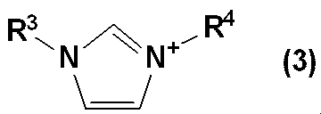
- 前記4級ホスホニウムイオンが、式(4)で示される請求項3記載の電解液用添加剤。

- 請求項1~7のいずれか1項記載の電解液用添加剤と、有機溶媒と、電解質塩とを含む電解液。 An electrolyte solution comprising the electrolyte solution additive according to any one of claims 1 to 7, an organic solvent, and an electrolyte salt.
- 前記有機溶媒が、カーボネート類である請求項8記載の電解液。 The electrolytic solution according to claim 8, wherein the organic solvent is a carbonate.
- 前記カーボネート類が、混合溶媒である請求項9記載の電解液。 10. The electrolytic solution according to claim 9, wherein the carbonate is a mixed solvent.
- 請求項8~10のいずれか1項記載の電解液を用いて構成される蓄電デバイス。 An electricity storage device comprising the electrolytic solution according to any one of claims 8 to 10.
- 請求項1~7のいずれか1項記載の電解液用添加剤を用いて構成される蓄電デバイス。 An electricity storage device comprising the additive for electrolyte solution according to any one of claims 1 to 7.
- 二次電池または電気二重層キャパシタである請求項11または12の蓄電デバイス。 The electricity storage device according to claim 11 or 12, which is a secondary battery or an electric double layer capacitor.
- 請求項1~7のいずれか1項記載の電解液用添加剤を、溶媒および電解質塩を含む電解液に加え、電解液の耐電圧を向上させる方法。 A method for improving the withstand voltage of an electrolytic solution by adding the electrolytic solution additive according to any one of claims 1 to 7 to an electrolytic solution containing a solvent and an electrolyte salt.
Priority Applications (4)
| Application Number | Priority Date | Filing Date | Title |
|---|---|---|---|
| CN201680055399.0A CN108140888B (en) | 2015-09-25 | 2016-07-06 | Additive for electrolyte |
| US15/761,201 US10658700B2 (en) | 2015-09-25 | 2016-07-06 | Additive for electrolyte solutions |
| KR1020187008008A KR102599251B1 (en) | 2015-09-25 | 2016-07-06 | Additives for electrolytes |
| EP16848377.4A EP3355400A4 (en) | 2015-09-25 | 2016-07-06 | Additive for electrolyte solutions |
Applications Claiming Priority (2)
| Application Number | Priority Date | Filing Date | Title |
|---|---|---|---|
| JP2015187773A JP6601094B2 (en) | 2015-09-25 | 2015-09-25 | Additive for electrolyte |
| JP2015-187773 | 2015-09-25 |
Publications (1)
| Publication Number | Publication Date |
|---|---|
| WO2017051587A1 true WO2017051587A1 (en) | 2017-03-30 |
Family
ID=58385970
Family Applications (1)
| Application Number | Title | Priority Date | Filing Date |
|---|---|---|---|
| PCT/JP2016/070012 WO2017051587A1 (en) | 2015-09-25 | 2016-07-06 | Additive for electrolyte solutions |
Country Status (6)
| Country | Link |
|---|---|
| US (1) | US10658700B2 (en) |
| EP (1) | EP3355400A4 (en) |
| JP (1) | JP6601094B2 (en) |
| KR (1) | KR102599251B1 (en) |
| CN (1) | CN108140888B (en) |
| WO (1) | WO2017051587A1 (en) |
Families Citing this family (12)
| Publication number | Priority date | Publication date | Assignee | Title |
|---|---|---|---|---|
| JP7012660B2 (en) | 2016-04-01 | 2022-02-14 | ノームズ テクノロジーズ インコーポレイテッド | Phosphorus-containing modified ionic liquid |
| JP7296893B2 (en) | 2017-07-17 | 2023-06-23 | ノームズ テクノロジーズ インコーポレイテッド | Phosphorus-containing electrolyte |
| KR102302558B1 (en) * | 2018-08-29 | 2021-09-16 | 주식회사 엘지화학 | Aqueous electrolyte and a pseudocapacitor comprising the same |
| JP7026974B2 (en) * | 2018-09-04 | 2022-03-01 | 国立研究開発法人物質・材料研究機構 | Electrolyte for lithium-air battery and lithium-air battery using it |
| CN110071329B (en) * | 2018-11-27 | 2021-06-22 | 欣旺达电子股份有限公司 | Lithium battery and electrolyte thereof |
| KR20210094062A (en) * | 2018-12-05 | 2021-07-28 | 쇼와덴코머티리얼즈가부시끼가이샤 | Electrolytes and Electrochemical Devices |
| JPWO2020116583A1 (en) * | 2018-12-05 | 2021-10-21 | 昭和電工マテリアルズ株式会社 | Electrolytes and electrochemical devices |
| CN113632285B (en) * | 2019-03-25 | 2023-10-03 | 日清纺控股株式会社 | Additive for electrolyte |
| CN109884148A (en) * | 2019-04-03 | 2019-06-14 | 南方科技大学 | A kind of reference electrode and its application method |
| JP7150799B2 (en) * | 2020-11-19 | 2022-10-11 | プライムプラネットエナジー&ソリューションズ株式会社 | Non-aqueous electrolyte secondary battery |
| CN113078355A (en) * | 2021-02-07 | 2021-07-06 | 东莞市杉杉电池材料有限公司 | Ternary lithium ion battery electrolyte and ion battery thereof |
| CN113381073B (en) * | 2021-07-27 | 2022-03-01 | 中节能万润股份有限公司 | Silicon sulfonate non-aqueous electrolyte additive and application thereof |
Citations (6)
| Publication number | Priority date | Publication date | Assignee | Title |
|---|---|---|---|---|
| US3141898A (en) * | 1961-01-03 | 1964-07-21 | Minnesota Mining & Mfg | 2, 2-dimethyl-2-silaalkane-sulfonic acids and their salts |
| JP2002359001A (en) * | 2001-05-11 | 2002-12-13 | Samsung Sdi Co Ltd | Electrolyte for lithium secondary battery and lithium secondary battery containing it |
| JP2005535690A (en) * | 2002-08-06 | 2005-11-24 | ゼネラル・エレクトリック・カンパニイ | Antistatic agent and polymer composition obtained from said antistatic agent |
| WO2009020038A1 (en) * | 2007-08-03 | 2009-02-12 | Idemitsu Kosan Co., Ltd. | Lubricant base oil and lubricant composition |
| WO2013005712A1 (en) * | 2011-07-04 | 2013-01-10 | 日清紡ホールディングス株式会社 | Ionic liquid |
| WO2014061484A1 (en) * | 2012-10-16 | 2014-04-24 | 日清紡ホールディングス株式会社 | Electrolyte salt and electrolyte for electricity storage device, and electricity storage device |
Family Cites Families (11)
| Publication number | Priority date | Publication date | Assignee | Title |
|---|---|---|---|---|
| JP3957415B2 (en) | 1998-10-20 | 2007-08-15 | 日立マクセル株式会社 | Non-aqueous secondary battery |
| JP4863008B2 (en) * | 2001-03-26 | 2012-01-25 | 日清紡ホールディングス株式会社 | Ionic liquid |
| CN100385727C (en) * | 2002-03-08 | 2008-04-30 | 三菱化学株式会社 | Nonaqueous electrolyte and lithium secondary battery employing the same |
| JPWO2003091198A1 (en) * | 2002-04-24 | 2005-09-02 | 日清紡績株式会社 | Ionic liquid and dehydration method, electric double layer capacitor and secondary battery |
| JP4972922B2 (en) | 2005-12-14 | 2012-07-11 | セントラル硝子株式会社 | Non-aqueous electrolyte battery electrolyte and non-aqueous electrolyte battery |
| JP5237681B2 (en) * | 2007-08-03 | 2013-07-17 | 出光興産株式会社 | Lubricating base oil and lubricating oil composition |
| DE102008021271A1 (en) * | 2008-04-29 | 2010-01-28 | Merck Patent Gmbh | Reactive ionic liquids |
| JP2010205870A (en) | 2009-03-03 | 2010-09-16 | Gunma Univ | Electrolyte additive for electric double-layer capacitor, electrolyte, and electric double-layer capacitor |
| JP2012038900A (en) | 2010-08-06 | 2012-02-23 | Jm Energy Corp | Lithium ion capacitor |
| EP2738862B1 (en) * | 2011-07-28 | 2020-12-16 | FUJIFILM Wako Pure Chemical Corporation | Electrolyte solution for electrochemical devices |
| WO2014036026A1 (en) * | 2012-08-30 | 2014-03-06 | Asahi Kasei Kabushiki Kaisha | Materials for battery electrolytes and methods for use |
-
2015
- 2015-09-25 JP JP2015187773A patent/JP6601094B2/en active Active
-
2016
- 2016-07-06 EP EP16848377.4A patent/EP3355400A4/en not_active Withdrawn
- 2016-07-06 CN CN201680055399.0A patent/CN108140888B/en active Active
- 2016-07-06 WO PCT/JP2016/070012 patent/WO2017051587A1/en active Application Filing
- 2016-07-06 KR KR1020187008008A patent/KR102599251B1/en active IP Right Grant
- 2016-07-06 US US15/761,201 patent/US10658700B2/en active Active
Patent Citations (6)
| Publication number | Priority date | Publication date | Assignee | Title |
|---|---|---|---|---|
| US3141898A (en) * | 1961-01-03 | 1964-07-21 | Minnesota Mining & Mfg | 2, 2-dimethyl-2-silaalkane-sulfonic acids and their salts |
| JP2002359001A (en) * | 2001-05-11 | 2002-12-13 | Samsung Sdi Co Ltd | Electrolyte for lithium secondary battery and lithium secondary battery containing it |
| JP2005535690A (en) * | 2002-08-06 | 2005-11-24 | ゼネラル・エレクトリック・カンパニイ | Antistatic agent and polymer composition obtained from said antistatic agent |
| WO2009020038A1 (en) * | 2007-08-03 | 2009-02-12 | Idemitsu Kosan Co., Ltd. | Lubricant base oil and lubricant composition |
| WO2013005712A1 (en) * | 2011-07-04 | 2013-01-10 | 日清紡ホールディングス株式会社 | Ionic liquid |
| WO2014061484A1 (en) * | 2012-10-16 | 2014-04-24 | 日清紡ホールディングス株式会社 | Electrolyte salt and electrolyte for electricity storage device, and electricity storage device |
Non-Patent Citations (1)
| Title |
|---|
| See also references of EP3355400A4 * |
Also Published As
| Publication number | Publication date |
|---|---|
| US10658700B2 (en) | 2020-05-19 |
| EP3355400A4 (en) | 2019-05-29 |
| KR20180058717A (en) | 2018-06-01 |
| CN108140888A (en) | 2018-06-08 |
| JP6601094B2 (en) | 2019-11-06 |
| US20180269529A1 (en) | 2018-09-20 |
| KR102599251B1 (en) | 2023-11-07 |
| CN108140888B (en) | 2021-01-15 |
| JP2017062955A (en) | 2017-03-30 |
| EP3355400A1 (en) | 2018-08-01 |
Similar Documents
| Publication | Publication Date | Title |
|---|---|---|
| JP6601094B2 (en) | Additive for electrolyte | |
| EP3240094B1 (en) | Electrolyte solution for secondary batteries, and secondary battery comprising the same | |
| JP5001508B2 (en) | Non-aqueous electrolyte secondary battery and non-aqueous electrolyte electric double layer capacitor | |
| KR102025969B1 (en) | METHOD FOR STABILIZING LiPF6, ELECTROLYTE SOLUTION FOR NONAQUEOUS SECONDARY BATTERIES HAVING EXCELLENT THERMAL STABILITY, AND NONAQUEOUS SECONDARY BATTERY HAVING EXCELLENT THERMAL STABILITY | |
| CN104078706A (en) | Electrolyte solution for lithium metal battery, and lithium metal battery | |
| CN111326783B (en) | Lithium ion battery | |
| JP2010503198A (en) | Electrolyte solution and super high capacity capacitor including the same | |
| JP2010050021A (en) | Nonaqueous electrolyte for battery and nonaqueous electrolyte secondary battery having the same | |
| JP5621745B2 (en) | Air battery electrolyte | |
| JP7035579B2 (en) | Additives for electrolytes | |
| EP3240000A1 (en) | Electricity storage device | |
| JP6831180B2 (en) | Power storage device and its manufacturing method | |
| WO2021176920A1 (en) | Electrolyte solution for power storage device, and ionic liquid | |
| CN113632285B (en) | Additive for electrolyte | |
| JP2009105028A (en) | Ammonium salt, electrolyte using same, electrolyte, additive, and electricity accumulation device | |
| JP2010108974A (en) | Quinuclidinium salt-containing electrolyte |
Legal Events
| Date | Code | Title | Description |
|---|---|---|---|
| 121 | Ep: the epo has been informed by wipo that ep was designated in this application |
Ref document number: 16848377 Country of ref document: EP Kind code of ref document: A1 |
|
| WWE | Wipo information: entry into national phase |
Ref document number: 15761201 Country of ref document: US |
|
| ENP | Entry into the national phase |
Ref document number: 20187008008 Country of ref document: KR Kind code of ref document: A |
|
| NENP | Non-entry into the national phase |
Ref country code: DE |
|
| WWE | Wipo information: entry into national phase |
Ref document number: 2016848377 Country of ref document: EP |