WO2017047178A1 - 情報処理装置、情報処理方法及びプログラム - Google Patents
情報処理装置、情報処理方法及びプログラム Download PDFInfo
- Publication number
- WO2017047178A1 WO2017047178A1 PCT/JP2016/067709 JP2016067709W WO2017047178A1 WO 2017047178 A1 WO2017047178 A1 WO 2017047178A1 JP 2016067709 W JP2016067709 W JP 2016067709W WO 2017047178 A1 WO2017047178 A1 WO 2017047178A1
- Authority
- WO
- WIPO (PCT)
- Prior art keywords
- information processing
- display
- processing apparatus
- prediction
- prediction accuracy
- Prior art date
Links
- 230000010365 information processing Effects 0.000 title claims abstract description 189
- 238000003672 processing method Methods 0.000 title claims abstract description 7
- 230000033001 locomotion Effects 0.000 claims description 76
- 230000000694 effects Effects 0.000 claims description 11
- 238000012545 processing Methods 0.000 description 112
- 238000000034 method Methods 0.000 description 66
- 238000001514 detection method Methods 0.000 description 54
- 238000010586 diagram Methods 0.000 description 38
- 230000008569 process Effects 0.000 description 32
- 230000006870 function Effects 0.000 description 27
- 230000008859 change Effects 0.000 description 26
- 238000003384 imaging method Methods 0.000 description 17
- 238000004891 communication Methods 0.000 description 16
- 210000001508 eye Anatomy 0.000 description 15
- 230000001133 acceleration Effects 0.000 description 14
- 238000005516 engineering process Methods 0.000 description 8
- 230000004048 modification Effects 0.000 description 8
- 238000012986 modification Methods 0.000 description 8
- 230000000007 visual effect Effects 0.000 description 8
- 210000003128 head Anatomy 0.000 description 7
- 230000007423 decrease Effects 0.000 description 5
- 230000003287 optical effect Effects 0.000 description 5
- 230000009467 reduction Effects 0.000 description 5
- 125000002066 L-histidyl group Chemical group [H]N1C([H])=NC(C([H])([H])[C@](C(=O)[*])([H])N([H])[H])=C1[H] 0.000 description 4
- 238000004458 analytical method Methods 0.000 description 4
- 230000005540 biological transmission Effects 0.000 description 4
- 238000004590 computer program Methods 0.000 description 3
- 230000003247 decreasing effect Effects 0.000 description 3
- 238000009877 rendering Methods 0.000 description 3
- 238000002834 transmittance Methods 0.000 description 3
- 238000013459 approach Methods 0.000 description 2
- 230000036772 blood pressure Effects 0.000 description 2
- 238000004364 calculation method Methods 0.000 description 2
- 230000004424 eye movement Effects 0.000 description 2
- 239000005357 flat glass Substances 0.000 description 2
- 230000004807 localization Effects 0.000 description 2
- 238000013507 mapping Methods 0.000 description 2
- 239000003550 marker Substances 0.000 description 2
- 239000011159 matrix material Substances 0.000 description 2
- 230000001151 other effect Effects 0.000 description 2
- 210000001747 pupil Anatomy 0.000 description 2
- 239000004065 semiconductor Substances 0.000 description 2
- 230000035900 sweating Effects 0.000 description 2
- 241000985694 Polypodiopsida Species 0.000 description 1
- 229910003798 SPO2 Inorganic materials 0.000 description 1
- 101100478210 Schizosaccharomyces pombe (strain 972 / ATCC 24843) spo2 gene Proteins 0.000 description 1
- 230000009471 action Effects 0.000 description 1
- 230000003466 anti-cipated effect Effects 0.000 description 1
- QVGXLLKOCUKJST-UHFFFAOYSA-N atomic oxygen Chemical compound [O] QVGXLLKOCUKJST-UHFFFAOYSA-N 0.000 description 1
- 230000003190 augmentative effect Effects 0.000 description 1
- 230000006399 behavior Effects 0.000 description 1
- 239000008280 blood Substances 0.000 description 1
- 210000004369 blood Anatomy 0.000 description 1
- 230000036760 body temperature Effects 0.000 description 1
- 210000004556 brain Anatomy 0.000 description 1
- 210000005252 bulbus oculi Anatomy 0.000 description 1
- 230000009194 climbing Effects 0.000 description 1
- 238000013500 data storage Methods 0.000 description 1
- 238000012217 deletion Methods 0.000 description 1
- 230000037430 deletion Effects 0.000 description 1
- 210000005069 ears Anatomy 0.000 description 1
- 230000008451 emotion Effects 0.000 description 1
- 230000002996 emotional effect Effects 0.000 description 1
- 238000007667 floating Methods 0.000 description 1
- 239000011521 glass Substances 0.000 description 1
- 230000006872 improvement Effects 0.000 description 1
- 230000003993 interaction Effects 0.000 description 1
- 239000004973 liquid crystal related substance Substances 0.000 description 1
- 230000007774 longterm Effects 0.000 description 1
- 239000000463 material Substances 0.000 description 1
- 239000000203 mixture Substances 0.000 description 1
- 230000003183 myoelectrical effect Effects 0.000 description 1
- 229910052760 oxygen Inorganic materials 0.000 description 1
- 239000001301 oxygen Substances 0.000 description 1
- 230000002093 peripheral effect Effects 0.000 description 1
- 230000029058 respiratory gaseous exchange Effects 0.000 description 1
- 210000001525 retina Anatomy 0.000 description 1
- 239000004984 smart glass Substances 0.000 description 1
- 230000005236 sound signal Effects 0.000 description 1
- 239000013589 supplement Substances 0.000 description 1
Images


Classifications
-
- G—PHYSICS
- G06—COMPUTING; CALCULATING OR COUNTING
- G06V—IMAGE OR VIDEO RECOGNITION OR UNDERSTANDING
- G06V20/00—Scenes; Scene-specific elements
- G06V20/60—Type of objects
- G06V20/64—Three-dimensional objects
-
- G—PHYSICS
- G02—OPTICS
- G02B—OPTICAL ELEMENTS, SYSTEMS OR APPARATUS
- G02B27/00—Optical systems or apparatus not provided for by any of the groups G02B1/00 - G02B26/00, G02B30/00
- G02B27/01—Head-up displays
- G02B27/017—Head mounted
- G02B27/0172—Head mounted characterised by optical features
-
- G—PHYSICS
- G06—COMPUTING; CALCULATING OR COUNTING
- G06F—ELECTRIC DIGITAL DATA PROCESSING
- G06F18/00—Pattern recognition
- G06F18/20—Analysing
- G06F18/22—Matching criteria, e.g. proximity measures
-
- G—PHYSICS
- G06—COMPUTING; CALCULATING OR COUNTING
- G06F—ELECTRIC DIGITAL DATA PROCESSING
- G06F3/00—Input arrangements for transferring data to be processed into a form capable of being handled by the computer; Output arrangements for transferring data from processing unit to output unit, e.g. interface arrangements
- G06F3/01—Input arrangements or combined input and output arrangements for interaction between user and computer
- G06F3/011—Arrangements for interaction with the human body, e.g. for user immersion in virtual reality
-
- G—PHYSICS
- G06—COMPUTING; CALCULATING OR COUNTING
- G06F—ELECTRIC DIGITAL DATA PROCESSING
- G06F3/00—Input arrangements for transferring data to be processed into a form capable of being handled by the computer; Output arrangements for transferring data from processing unit to output unit, e.g. interface arrangements
- G06F3/01—Input arrangements or combined input and output arrangements for interaction between user and computer
- G06F3/048—Interaction techniques based on graphical user interfaces [GUI]
- G06F3/0481—Interaction techniques based on graphical user interfaces [GUI] based on specific properties of the displayed interaction object or a metaphor-based environment, e.g. interaction with desktop elements like windows or icons, or assisted by a cursor's changing behaviour or appearance
- G06F3/04815—Interaction with a metaphor-based environment or interaction object displayed as three-dimensional, e.g. changing the user viewpoint with respect to the environment or object
-
- G—PHYSICS
- G06—COMPUTING; CALCULATING OR COUNTING
- G06T—IMAGE DATA PROCESSING OR GENERATION, IN GENERAL
- G06T11/00—2D [Two Dimensional] image generation
-
- G—PHYSICS
- G06—COMPUTING; CALCULATING OR COUNTING
- G06T—IMAGE DATA PROCESSING OR GENERATION, IN GENERAL
- G06T19/00—Manipulating 3D models or images for computer graphics
- G06T19/006—Mixed reality
-
- G—PHYSICS
- G06—COMPUTING; CALCULATING OR COUNTING
- G06T—IMAGE DATA PROCESSING OR GENERATION, IN GENERAL
- G06T5/00—Image enhancement or restoration
- G06T5/50—Image enhancement or restoration using two or more images, e.g. averaging or subtraction
-
- G—PHYSICS
- G06—COMPUTING; CALCULATING OR COUNTING
- G06T—IMAGE DATA PROCESSING OR GENERATION, IN GENERAL
- G06T5/00—Image enhancement or restoration
- G06T5/73—Deblurring; Sharpening
-
- G—PHYSICS
- G06—COMPUTING; CALCULATING OR COUNTING
- G06T—IMAGE DATA PROCESSING OR GENERATION, IN GENERAL
- G06T7/00—Image analysis
- G06T7/20—Analysis of motion
-
- G—PHYSICS
- G06—COMPUTING; CALCULATING OR COUNTING
- G06T—IMAGE DATA PROCESSING OR GENERATION, IN GENERAL
- G06T7/00—Image analysis
- G06T7/70—Determining position or orientation of objects or cameras
-
- G—PHYSICS
- G06—COMPUTING; CALCULATING OR COUNTING
- G06V—IMAGE OR VIDEO RECOGNITION OR UNDERSTANDING
- G06V10/00—Arrangements for image or video recognition or understanding
- G06V10/70—Arrangements for image or video recognition or understanding using pattern recognition or machine learning
- G06V10/74—Image or video pattern matching; Proximity measures in feature spaces
- G06V10/75—Organisation of the matching processes, e.g. simultaneous or sequential comparisons of image or video features; Coarse-fine approaches, e.g. multi-scale approaches; using context analysis; Selection of dictionaries
-
- G—PHYSICS
- G06—COMPUTING; CALCULATING OR COUNTING
- G06V—IMAGE OR VIDEO RECOGNITION OR UNDERSTANDING
- G06V20/00—Scenes; Scene-specific elements
- G06V20/20—Scenes; Scene-specific elements in augmented reality scenes
-
- G—PHYSICS
- G06—COMPUTING; CALCULATING OR COUNTING
- G06V—IMAGE OR VIDEO RECOGNITION OR UNDERSTANDING
- G06V40/00—Recognition of biometric, human-related or animal-related patterns in image or video data
- G06V40/10—Human or animal bodies, e.g. vehicle occupants or pedestrians; Body parts, e.g. hands
- G06V40/18—Eye characteristics, e.g. of the iris
-
- G—PHYSICS
- G09—EDUCATION; CRYPTOGRAPHY; DISPLAY; ADVERTISING; SEALS
- G09G—ARRANGEMENTS OR CIRCUITS FOR CONTROL OF INDICATING DEVICES USING STATIC MEANS TO PRESENT VARIABLE INFORMATION
- G09G3/00—Control arrangements or circuits, of interest only in connection with visual indicators other than cathode-ray tubes
- G09G3/20—Control arrangements or circuits, of interest only in connection with visual indicators other than cathode-ray tubes for presentation of an assembly of a number of characters, e.g. a page, by composing the assembly by combination of individual elements arranged in a matrix no fixed position being assigned to or needed to be assigned to the individual characters or partial characters
-
- G—PHYSICS
- G09—EDUCATION; CRYPTOGRAPHY; DISPLAY; ADVERTISING; SEALS
- G09G—ARRANGEMENTS OR CIRCUITS FOR CONTROL OF INDICATING DEVICES USING STATIC MEANS TO PRESENT VARIABLE INFORMATION
- G09G5/00—Control arrangements or circuits for visual indicators common to cathode-ray tube indicators and other visual indicators
-
- G—PHYSICS
- G02—OPTICS
- G02B—OPTICAL ELEMENTS, SYSTEMS OR APPARATUS
- G02B27/00—Optical systems or apparatus not provided for by any of the groups G02B1/00 - G02B26/00, G02B30/00
- G02B27/01—Head-up displays
- G02B27/0101—Head-up displays characterised by optical features
- G02B2027/0138—Head-up displays characterised by optical features comprising image capture systems, e.g. camera
-
- G—PHYSICS
- G02—OPTICS
- G02B—OPTICAL ELEMENTS, SYSTEMS OR APPARATUS
- G02B27/00—Optical systems or apparatus not provided for by any of the groups G02B1/00 - G02B26/00, G02B30/00
- G02B27/01—Head-up displays
- G02B27/0101—Head-up displays characterised by optical features
- G02B2027/014—Head-up displays characterised by optical features comprising information/image processing systems
-
- G—PHYSICS
- G06—COMPUTING; CALCULATING OR COUNTING
- G06T—IMAGE DATA PROCESSING OR GENERATION, IN GENERAL
- G06T2207/00—Indexing scheme for image analysis or image enhancement
- G06T2207/20—Special algorithmic details
- G06T2207/20172—Image enhancement details
- G06T2207/20201—Motion blur correction
-
- G—PHYSICS
- G06—COMPUTING; CALCULATING OR COUNTING
- G06T—IMAGE DATA PROCESSING OR GENERATION, IN GENERAL
- G06T2207/00—Indexing scheme for image analysis or image enhancement
- G06T2207/30—Subject of image; Context of image processing
- G06T2207/30244—Camera pose
-
- G—PHYSICS
- G06—COMPUTING; CALCULATING OR COUNTING
- G06V—IMAGE OR VIDEO RECOGNITION OR UNDERSTANDING
- G06V30/00—Character recognition; Recognising digital ink; Document-oriented image-based pattern recognition
- G06V30/10—Character recognition
- G06V30/22—Character recognition characterised by the type of writing
- G06V30/224—Character recognition characterised by the type of writing of printed characters having additional code marks or containing code marks
- G06V30/2247—Characters composed of bars, e.g. CMC-7
Definitions
- the present disclosure relates to an information processing apparatus, an information processing method, and a program.
- AR augmented reality
- AR virtual objects are generally displayed in association with the real object, such as being displayed on the surface of the real object or floating above the real object. For this reason, it is desirable that the display of the virtual object appropriately follow the change in the position or orientation of the real object.
- Patent Document 1 when the position or orientation of a real object is recognized and a virtual object is displayed based on the recognition result, the display is changed according to the recognition stability. Techniques for making them disclosed are disclosed.
- the present disclosure proposes a new and improved information processing apparatus, information processing method, and program capable of further reducing discomfort caused by disordered display of a virtual object.
- the prediction accuracy estimation unit that estimates the prediction accuracy related to the prediction of the position or orientation of the real object, and the virtual object corresponding to the real object based on the estimation result by the prediction accuracy estimation unit
- an output control unit that outputs information for display on the information processing apparatus.
- the prediction accuracy related to the prediction of the position or orientation of the real object is estimated by the processor, and the virtual object corresponding to the real object is displayed on the display unit based on the estimation result of the prediction accuracy.
- An information processing method including outputting information for display is provided.
- the computer corresponds to the real object based on a prediction accuracy estimation unit that estimates the prediction accuracy related to the prediction of the position or orientation of the real object, and an estimation result by the prediction accuracy estimation unit.
- a program for functioning as an output control unit that outputs information for displaying a virtual object on a display unit is provided.
- FIG. 6 is an explanatory diagram for explaining a UI example according to the embodiment.
- FIG. 6 is an explanatory diagram for explaining a UI example according to the embodiment.
- FIG. 6 is an explanatory diagram for explaining a UI example according to the embodiment.
- FIG. 6 is an explanatory diagram for explaining a UI example according to the embodiment.
- FIG. 6 is an explanatory diagram for explaining a UI example according to the embodiment.
- FIG. 6 is an explanatory diagram for explaining a UI example according to the embodiment.
- FIG. 6 is an explanatory diagram for explaining a UI example according to the embodiment.
- FIG. 6 is an explanatory diagram for explaining a UI example according to the embodiment.
- 5 is a flowchart illustrating an example of a flow of virtual object display control processing executed in the information processing apparatus according to the embodiment.
- 5 is a flowchart illustrating an example of a flow of virtual object display control processing executed in the information processing apparatus according to the embodiment.
- FIG. 6 is an explanatory diagram for explaining a UI example according to the embodiment.
- 5 is a flowchart illustrating an example of a flow of virtual object display control processing executed in the information processing apparatus according to the embodiment.
- FIG. 6 is an explanatory diagram for explaining a UI example according to the embodiment.
- FIG. 6 is an explanatory diagram for explaining a UI example according to the embodiment.
- FIG. 6 is an explanatory diagram for explaining a UI example according to the embodiment.
- It is a block diagram which shows an example of the logical structure of HMD which concerns on the embodiment. It is a block diagram which shows an example of the logical structure of HMD which concerns on the embodiment.
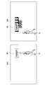
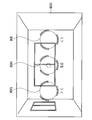
- FIG. 1 is a diagram illustrating an example of an external configuration of the information processing apparatus 1 according to the present embodiment.
- the information processing apparatus 1 illustrated in FIG. 1 is an apparatus that is also referred to as smart glass or HMD (Head Mounted Display).
- the information processing apparatus 1 includes a mounting unit 50 having a frame structure that circulates around the user's head, for example, and is fixed to the user's head by the mounting unit 50.
- the information processing apparatus 1 is configured such that a pair of display units 20A and 20B for the left eye and the right eye are arranged in front of the user's eyes in the wearing state as shown in FIG.
- a transmissive display is used for the display unit 20, and the information processing apparatus 1 can be in a through state, that is, a transparent or translucent state by controlling the transmittance of the transmissive display.
- a through state that is, a transparent or translucent state by controlling the transmittance of the transmissive display.
- the display unit 20 can display an image such as a text or a figure in a transparent or translucent state so that an AR virtual object can be superimposed on a real space landscape. That is, the information processing apparatus 1 may be realized as a transmissive HMD.
- the transmissive HMD as shown in FIG. 1, the information processing apparatus 1 is fixed to the user's head by the mounting unit 50, and the relative positional relationship between the user's eyes and the display unit 20 is determined. It is desirable to be fixed. This is because when the relative positional relationship changes, the position on the display where the virtual object is to be displayed can change.
- the display unit 20 can display the captured image of the real space captured by the imaging units 10A and 10B while superimposing the virtual object on the captured image of the real space.
- the display unit 20 can also display a virtual object superimposed on the image in the virtual space while displaying an image as if the imaging unit 10A and 10B captured the virtual space. That is, the information processing apparatus 1 may be realized as an immersive (video through) HMD.
- the display unit 20 may be realized as an LED light source or the like that directly projects an image on the user's retina. That is, the information processing apparatus 1 may be realized as a projection type HMD.
- the content may be moving image content such as a movie or video clip, still image content captured by a digital still camera, or data such as an electronic book.
- Such content is assumed to be any data to be displayed, such as image data created by a user with a personal computer, text data, computer use data such as spreadsheet data, and game images based on game programs.
- the imaging units 10 ⁇ / b> A and 10 ⁇ / b> B are arranged so as to capture an image of a real space in a direction visually recognized by the user when the user wears the information processing apparatus 1.
- the imaging units 10 ⁇ / b> A and 10 ⁇ / b> B may be realized as a stereo camera that can also acquire information indicating the distance in the direction visually recognized by the user (hereinafter also referred to as depth information).
- depth information information indicating the distance in the direction visually recognized by the user
- the imaging units 10A and 10B are realized as a stereo camera, the information processing apparatus 1 can accurately recognize the shape and posture of a real object existing in real space.
- the imaging units 10A and 10B are also referred to as outward stereo cameras 10.
- the imaging units 10 ⁇ / b> C and 10 ⁇ / b> D are arranged so as to capture the user's direction, more specifically, the user's eyes as an imaging range, when the user wears the information processing apparatus 1.
- the imaging units 10C and 10D may be realized as a stereo camera that can also acquire depth information in the direction of both eyes of the user.
- the imaging units 10C and 10D are realized as a stereo camera, the information processing apparatus 1 can more accurately recognize the position of the user's eyeball, the position of the pupil, the direction of the line of sight, and the like.
- the imaging units 10C and 10D are also referred to as an inward stereo camera 10.
- the information processing apparatus 1 may have a speaker or an earphone speaker. Further, the information processing apparatus 1 may include a microphone that acquires external sound.
- the information processing apparatus 1 may be formed of a wearing unit that is generally a spectacle type or a head-mounted type. At least in the present embodiment, the display unit 20 is provided in front of the user's eyes. That's fine. In addition to a pair of display units 20 corresponding to both eyes, one display unit 20 corresponding to one eye may be provided.
- two speakers or earphone speakers may be provided corresponding to the left and right ears, or one speaker or earphone speaker may be provided corresponding to one ear.
- One or more microphones may be provided, and the arrangement thereof is arbitrary.
- the information processing apparatus 1 is assumed to be realized as a transmissive HMD as an example.
- An image displayed on the display unit 20 (transmission type display) of the information processing apparatus 1 (including a background that is visible through transmission and a virtual object that is superimposed and displayed) is also referred to as a real space image below.
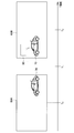
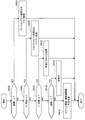
- FIG. 2 shows an example of a change in position or orientation of a real object included in the real space image. In the figure, time flows from left to right.
- the information processing apparatus 1 displays a virtual object at a position or posture corresponding to the predicted position or posture while predicting a change in the position or posture of the real object 70. Therefore, first, the information processing apparatus 1 at time T 0, the information about the real object 70 included in the real space image 60A detects (sensing). For example, the information processing apparatus 1 captures an image of the real space from the user's viewpoint with a camera and reads it as digital data. Next, the information processing apparatus 1 predicts a change in the position or orientation of the real object 70 at time T 2 based on the information detected at time T 0 at time T 1 .
- the information processing apparatus 1 recognizes the real object 70 based on the captured image and predicts a change in the position or orientation of the recognized real object 70. Then, the information processing apparatus 1 at time T 2, to display the virtual object 80 in the real space image 60B on the basis of the prediction result.
- time T 0 when information for prediction is detected
- time T 2 when the virtual object 80 is displayed. If the real object 70 is not accurately predicted in this time lag, the display object is disturbed such that the virtual object 80 is displayed at a position or posture that deviates from the position or posture to be originally displayed. It can be uncomfortable.
- this point will be described with reference to FIGS. 3 and 4.
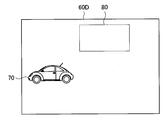
- Figure 3 if the prediction is performed accurately, it shows an example of a real space image 60C displayed at time T 2. As shown in the real space image 60 ⁇ / b> C, the virtual object 80 is accurately superimposed on the position of the real object 70. For this reason, there is no confusion or discomfort to the user.
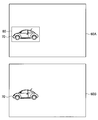
- Figure 4 when the prediction is not performed accurately, it shows an example of a real space image 60D displayed at time T 2. As shown in the real space image 60D, the virtual object 80 is displayed at a position away from the position of the real object 70. Such a display shift causes confusion or discomfort to the user.
- the same technical problem may occur not only in a device having a transmissive display but also in a video-through HMD having a non-transmissive display, for example.
- the above-described display disorder may occur similarly.
- Patent Document 1 it is considered that it is difficult to sufficiently suppress display disturbance by the technique described in Patent Document 1. For example, even if the recognition is stable, the display of the virtual object may be disturbed if the prediction accuracy is low. For example, when the real object is operating irregularly, the display may be noticeably disturbed.
- Patent Document 1 a virtual object is superimposed and displayed on an image in real space captured at time T 0 at time T 2 . That is, the technique described in Patent Document 1 does not take into consideration that the real object moves or changes its posture during the time lag between time T 0 and time T 2. It cannot solve the problem.
- the information processing apparatus 1 performs display control based on the prediction accuracy related to the time lag, thereby suppressing disturbance of display of the virtual object, and confusion given to the user even when the display is disturbed. Or discomfort can be reduced.
- time T 0 is also referred to as detection time
- time T 2 is also referred to as display time.
- FIG. 5 is a block diagram illustrating an example of a logical configuration of the information processing apparatus according to the present embodiment.
- the information processing apparatus 1 includes a real object detection unit 100, a real object recognition unit 120, a real object prediction unit 140, a viewpoint detection unit 200, a viewpoint recognition unit 220, and a viewpoint prediction unit 240.
- a drawing delay detection unit 300 a visual field state prediction unit 400, a prediction accuracy estimation unit 500, an output control unit 600, and a display unit 700.
- Real object detection unit 100 has a function of detecting information about the real object in the detection time T 0.
- the real object detection unit 100 acquires information detected by a sensor that uses a real object as a sensing target. Examples of such sensors include cameras, depth sensors, infrared sensors, and radio wave sensors.
- the real object detection unit 100 can be realized as the outward stereo camera 10.
- the real object recognition unit 120 has a function of recognizing a real object based on information acquired by the real object detection unit 100.
- the real object recognition unit 120 recognizes the position or orientation of the real object.
- the position or orientation of the real object means the position or orientation of the real object in the world coordinate system.
- the world coordinate system is a coordinate system that represents absolute coordinates that are fixedly defined in real space.
- recognition of a real object may be performed by collating a feature amount calculated from a captured image with a feature amount of a real object registered in advance.
- the feature amount can be calculated by a known feature amount calculation technique such as SIFT method or Random Ferns method.
- the real object may be recognized by recognizing a known figure or symbol attached to the real object, an artificial marker (for example, a barcode or QR code (registered trademark)), a natural marker, or the like.
- an artificial marker for example, a barcode or QR code (registered trademark)
- QR code registered trademark
- the recognition of the real object may be performed based on the depth information for each pixel based on the image obtained by the stereo camera and the reliability of the depth information.
- the real object recognition unit 120 determines the position and shape of the real object (that is, binocular parallax) based on the difference between real objects (binocular parallax) on a plurality of captured images in the same real space from different viewpoints. Recognize irregularities in real space as seen from the imaging unit. Note that, due to the characteristics of stereo image recognition, the reliability of depth information related to a region with little change in hue or the like may be reduced.
- the depth information may be acquired using an arbitrary technique such as a depth sensor using a ToF (Time of Flight) method.
- the real object prediction unit 140 has a function of performing prediction related to the real object at the display time T 2 based on the recognition result by the real object recognition unit 120.
- the real object prediction unit 140 has a function of predicting the position or orientation of the real object in the display time T 2.
- the real object prediction unit 140 accumulates a log of the position or orientation of the recognized real object, and performs prediction based on the accumulated log. Below, an example of the prediction method is demonstrated.
- the real object prediction unit 140 predicts the position where the real object at the coordinates (x t0 , y t0 , z t0 ) at the time t0 exists at the time t by the following expression.
- the viewpoint detection unit 200 has a function of detecting information regarding the viewpoint at the detection time T 0 .
- the viewpoint may mean the position or posture of the user's eyes (that is, the direction of the line of sight), may mean the position or posture of the display unit 700, or may include both of these.
- the viewpoint detection unit 200 acquires information detected by a sensor whose target is the user or the information processing apparatus 1 itself. Examples of such sensors include a camera, a depth sensor, a gyro sensor, an acceleration sensor, and a GNSS (Global Navigation Satellite System).
- the viewpoint detection unit 200 can be realized as the inward stereo camera 10 and the outward stereo camera 10.
- an image captured by the inward stereo camera 10 can be used to recognize which direction the eye is facing relative to the relative coordinate system on the face.
- the image captured by the outward stereo camera 10 is used for recognizing the movement of feature points in the external world and for recognizing the movement of the viewpoint (that is, the head) in the world coordinate system (that is, for the SLAM method described later).
- These recognitions are performed by a viewpoint recognition unit 220 described later.
- the viewpoint recognition unit 220 has a function of recognizing the position or orientation of the viewpoint based on the information acquired by the viewpoint detection unit 200.
- the position or orientation of the viewpoint means the position or orientation of the viewpoint in the world coordinate system.
- viewpoint recognition may be performed by a known image recognition technique such as SfM (Structure from Motion) method or SLAM (Simultaneous Localization And Mapping) method.
- the recognition of the viewpoint is performed by, for example, recognizing the relative position and orientation of the coordinate system of the reference environment (real space) with respect to the coordinate system unique to the information processing apparatus 1.
- the processor of the information processing device 1 uses a state variable including the position, posture, velocity and angular velocity of the device, and the position of at least one feature point included in the captured image as an extended Kalman filter. Updating is performed for each frame of the captured image based on the principle.
- the position and orientation of the reference environment based on the position and orientation of the apparatus can be recognized using the input image from the monocular camera.
- SLAM method can be found in, for example, “Real-Time Simultaneous Localization and Mapping with a Single Camera” (Andrew J. Davison, Proceedings of the 9th IEEE International Conference on Computer Vision Volume 2, 2003, pp.1403-1410) It is described in.
- the viewpoint may be recognized as long as it recognizes the relative position and orientation of the imaging unit in the real space.
- the environment recognition matrix may be recognized based on depth data from a depth sensor that can be provided in the imaging unit.
- the environment recognition matrix may be recognized based on output data from an environment recognition system such as an infrared distance measuring system or a motion capture system.
- an environment recognition system such as an infrared distance measuring system or a motion capture system.
- the recognition of the viewpoint may be performed by specifying the relative positional relationship of each frame image by stitching analysis of a series of frame images obtained by imaging the real space.
- the stitching analysis may be a two-dimensional stitching analysis in which each frame image is pasted on the base plane, or a three-dimensional stitching analysis in which each frame image is pasted at an arbitrary position in the space.
- the recognition of the viewpoint may be performed in combination with an inertial sensor such as an acceleration sensor or a gyro sensor included in the information processing apparatus 1. In that case, the viewpoint can be recognized at higher speed. Further, even when it is difficult to recognize a viewpoint based on a captured image due to motion blur caused by a user (camera position) moving at high speed, it is possible to recognize with a certain degree of accuracy.
- an inertial sensor such as an acceleration sensor or a gyro sensor included in the information processing apparatus 1.
- the viewpoint prediction unit 240 has a function of performing prediction related to the viewpoint at the display time T 2 based on the recognition result by the viewpoint recognition unit 220. For example, the viewpoint prediction unit 240 predicts the position or orientation of the viewpoint in the display time T 2. For this purpose, the viewpoint prediction unit 240 accumulates a log of the recognized viewpoint position or orientation, and performs prediction based on the accumulated log. As a specific prediction method, a prediction method similar to that described above with respect to the real object prediction unit 140 may be employed.
- Drawing the delay detection unit 300 has a function of detecting a time lag between the detection time T 0 and the display time T 2.
- the time lag may be a predetermined value or may change dynamically.
- the length of the time lag can vary by the processing time of various processing performed between the detection time T 0 until the display time T 2. For example, the time lag can be shortened when the processing load is low, and the time lag can be lengthened when the processing load is high.
- the length of the time lag can also vary depending on the operating frequency setting of the CPU, GPU, sensor, etc. for executing various processes, ON / OFF of the power saving setting, and the like.
- the drawing delay detection unit 300 can detect a time lag based on the processing load of various processes, the operation frequency setting, the power saving setting ON / OFF, and the like.
- Visibility in the state prediction unit 400 has a function of predicting the position or orientation of the real object appearing in the user's view at the display time T 2 (i.e., the real space image). This prediction is a prediction of the time lag from the time T 0 in which information for the prediction is detected until the time T 2 where the virtual object is displayed.
- the visual field state prediction unit 400 performs prediction based on the prediction results by the real object prediction unit 140 and the viewpoint prediction unit 240 regarding how the real object moves and how the viewpoint moves during this time lag. Do.
- the position or orientation of a real object in the user's field of view means the position or orientation of the real object on the display surface of the display unit 700 viewed from the user's eyes.
- the prediction accuracy estimation unit 500 has a function of estimating the prediction accuracy related to the prediction of the position or orientation of a real object shown on the display unit 700 (for example, transmitted through a transmissive display or displayed on a non-transmissive display). . Specifically, the prediction accuracy estimation unit 500 estimates the accuracy of prediction by the in-view state prediction unit 400. The prediction accuracy estimation unit 500 may estimate a low factor when the prediction accuracy is low.
- prediction accuracy estimation unit 500 may estimate the prediction accuracy based on the time lag between the detection time T 0 and the display time T 2. For example, the prediction accuracy estimation unit 500 estimates that the prediction accuracy is lower as the time lag is longer, and the prediction accuracy is higher as the time lag is shorter. This is because the longer the time lag, the greater the possibility of errors. In addition, the prediction accuracy estimation unit 500 may determine that the prediction accuracy is low when the time lag is equal to or greater than the threshold, and may determine that the prediction accuracy is high when the time lag is less than the threshold.
- the prediction accuracy estimation unit 500 may estimate the prediction accuracy based on at least one of the magnitude of the motion or regularity of the target used for prediction of the position or orientation of the real object or the viewpoint. Specifically, the prediction accuracy estimation unit 500 estimates the prediction accuracy lower as the movement of the object is larger, and estimates the prediction accuracy higher as the movement of the object is smaller. Similarly, the prediction accuracy estimation unit 500 estimates the prediction accuracy lower as the regularity of the motion of the object is lower, and estimates higher prediction accuracy as the regularity of the motion of the target is higher. As in the case of the time lag, a threshold value may be used. Note that the object here refers to, for example, a real object, the display unit 700, and the user's eyes.
- the prediction accuracy estimation unit 500 may estimate the prediction accuracy based on the magnitude or regularity of the movement of the real object. In addition, the prediction accuracy estimation unit 500 may estimate the prediction accuracy based on the magnitude or regularity of the movement of the display unit 700. The prediction accuracy estimation unit 500 may estimate the prediction accuracy based on the magnitude or regularity of the user's eye movement.
- the output control unit 600 controls display processing (drawing processing) of the virtual object by the display unit 700. Specifically, the output control unit 600 is in a position corresponding to the position of the real object predicted by the in-view state prediction unit 400 or in a position corresponding to the posture of the real object predicted by the in-view state prediction unit 400.
- Display virtual objects Thereby, for example, the virtual object can be displayed in a superimposed manner on the surface of the real object, or the virtual object can be displayed in association with the sky above the real object.
- the display position of the virtual object may mean a position in the real space perceived by the user (that is, a position in the world coordinate system), or a position on the display unit 700 (for example, a transmissive display). (That is, coordinates on the screen) may be meant.
- the display of the virtual object may differ depending on what is meant. For example, even if there is a sense of perspective as a position perceived by the user, it may be displayed at the same position on the display unit 700.
- the output control unit 600 controls display of the virtual object corresponding to the real object based on the estimation result by the prediction accuracy estimation unit 500. This is because display distortion is less likely to occur as the prediction accuracy is higher, and display disturbance is more likely to occur as the prediction accuracy is lower.
- the output control unit 600 can further suppress the disturbance of the display of the virtual object by performing the display in consideration of the prediction accuracy.
- the output control unit 600 displays the virtual object so that the higher the prediction accuracy, the higher the relevance with the corresponding real object, and the lower the prediction accuracy, the lower the relevance with the corresponding real object. May be displayed.
- the lower the prediction accuracy the more disturbed the display may be, for example, the virtual object is displayed at a position away from the real object.
- the relevance is displayed low (for example, roughly)
- the user even if the virtual object is displayed at a position away from the real object, the user roughly grasps the relevance. It is possible.
- the influence can be reduced by the display with low relevance.
- the prediction accuracy is high, the relevance is displayed so that the user can clearly grasp the relevance.
- a display with high relevance indicates that a virtual object is displayed in a small size
- a display with low relevance indicates that a virtual object is displayed in a large size.
- the smaller the virtual object is displayed the more the real object fits in the virtual object and the higher the relevance is expressed.
- the larger the virtual object is displayed the more the real object fits in the virtual object with a gap, and the lower the relevance is expressed.
- a highly relevant display indicates a display that does not apply motion blur processing
- a lowly relevant display indicates a display that applies motion blur processing.
- the display position of the virtual object becomes clear, and the relationship with the real object is clearly (ie, highly) expressed.
- motion blur processing is applied to a virtual object, the display position of the virtual object becomes ambiguous, and the relationship with the real object is ambiguously expressed (that is, low).
- the output control unit 600 may display the virtual object more clearly as the prediction accuracy is higher, and display the virtual object more ambiguously as the prediction accuracy is lower. More specifically, the output control unit 600 may blur and display the virtual object as the prediction accuracy is lower. This is because the lower the prediction accuracy, the more disturbed the display may be, for example, the virtual object is displayed at a position away from the real object. In such a case, the virtual object itself is displayed ambiguously (for example, lightly), and even if the virtual object is displayed at a position away from the real object, the impression of the shift may be weakened. Is possible. As described above, even when the display of the virtual object is disturbed, the influence can be reduced by the ambiguous display. When the prediction accuracy is high, the virtual object can be clearly displayed at an appropriate position. A specific UI example related to such display control will be described in detail later with reference to FIGS.
- the output control unit 600 may cause the display of the virtual object to be displayed according to a factor with low prediction accuracy. For example, the output control unit 600 selects a drawing method that can further reduce the influence of the display disturbance according to the factor. Thereby, even when the display of the virtual object is disturbed, it is possible to reduce the influence.
- the output control unit 600 controls the display of the virtual object, but more specifically, the output control unit 600 outputs information for causing the display unit 700 to display the virtual object.
- the output control unit 600 determines a region, posture, size, and the like for drawing the virtual object, generates image information obtained by rendering the virtual object, and outputs the generated image information. Then, the display unit 700 performs display based on this image information.
- the display unit 700 has a function of displaying information to the user.
- the display unit 700 displays a virtual object based on control by the output control unit 600.
- the display unit 700 may be a transmissive display device that displays a virtual object while transmitting a real object in the real space.
- the information processing apparatus 1 is realized as the transmissive HMD shown in FIG. 1, and the display unit 700 is realized as the display units 20A and 20B shown in FIG.
- the display unit 700 may be a non-transparent display device that further displays a virtual object while displaying the captured real object in real time.
- the information processing apparatus 1 can be realized as an immersive (video through) HMD.
- FIG. 5 illustrates an example in which each component is included in the same device, but the present technology is not limited to such an example.
- each component of the information processing apparatus 1 may be separately included in a plurality of apparatuses, and may be included separately in, for example, a server that performs information processing and a client that performs input / output.
- the various sensors may be environment-installed devices.
- the time lag detected by the drawing delay detection unit 300 may include, for example, a communication delay.
- an apparatus having a display unit 700 such as an HMD is also referred to as local
- a non-local apparatus such as a server on the cloud is also referred to as external.
- the real object detection unit 100 may be included locally or externally.
- a camera outside the vehicle can function as the real object detection unit 100.
- the real object recognition unit 120 may be included locally or externally.
- the entire recognition process may be performed on the cloud, or a part of the recognition process with a large load may be performed on the cloud.
- the real object prediction unit 140 may be included locally or externally. However, when the real object predicting unit 140 is included outside, the latency may increase and prediction may be difficult.
- the viewpoint detection unit 200 may be included locally or externally.
- a sensor included in the eyewear can function as the viewpoint detection unit 200.
- the viewpoint recognition unit 220 may be included locally or externally. However, the viewpoint recognition unit 220 is preferably included on the same side as the viewpoint detection unit 200.
- the viewpoint prediction unit 240 may be included locally or externally. However, when the viewpoint predicting unit 240 is included outside, the latency may increase and prediction may be difficult.
- the drawing delay detection unit 300 is desirably included locally. This is for detecting a delay including a communication delay between the local and the outside.
- the in-view state prediction unit 400 may be included locally or externally. However, when the in-view state prediction unit 400 is included outside, the latency may increase, and prediction may be difficult.
- the prediction accuracy estimation unit 500 may be included locally or externally. However, when the prediction accuracy estimation unit 500 is included outside, the latency may increase and prediction may be difficult.
- the output control unit 600 may be included locally, or may be included both locally and externally.
- the drawing of the virtual object may be performed on the cloud, and the output position alignment of the virtual object may be performed locally.
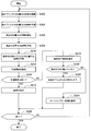
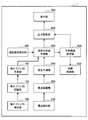
- FIG. 6 is a flowchart illustrating an example of the flow of a virtual object display control process executed in the information processing apparatus 1 according to the present embodiment.
- step S102 the real object recognition unit 120, based in the detection time T 0 the information detected by the real object detecting unit 100 recognizes the position or orientation of the real object (step S102). Then, the real object prediction unit 140 predicts the position or orientation of the real object in the display time T 2 (step S104).
- the viewpoint recognition unit 220 based on the information detected by the viewpoint detection unit 200 at the detection time T 0, recognizes the position or orientation of the viewpoint (step S106). Then, the viewpoint prediction unit 240 predicts the position or orientation of the viewpoint in the display time T 2 (step S108).
- the visual field state prediction unit 400 predicts the position or orientation of the real object in the visual field based on the prediction results by the real object prediction unit 140 and the viewpoint prediction unit 240 (step S110).
- the prediction accuracy estimation unit 500 estimates the prediction accuracy (step S112).
- the drawing delay detection unit 300 may detect the length of the time lag.
- the output control unit 600 determines whether or not the prediction accuracy is higher than a threshold value (step S114). When it determines with it being high (step S114 / YES), the output control part 600 displays a virtual object on the display part 700 using a normal display method (step S116). For example, the output control unit 600 displays a virtual object that is highly related to a real object. On the other hand, when it determines with it being low (step S114 / NO), the output control part 600 displays a virtual object on the display part 700 using the display method when accuracy is low (step S118). For example, the output control unit 600 displays a virtual object expressed with low relevance to the real object.
- step S120 / NO the process returns to step S102 again.
- step S120 / YES the process ends.
- the information processing apparatus 1 may change the size of the virtual object according to the prediction accuracy. For example, the information processing apparatus 1 displays the virtual object larger as the prediction accuracy is lower so as to include an area to be displayed. Further, the information processing apparatus 1 displays the virtual object smaller as the prediction accuracy is lower, so as to be included in the region to be displayed. Such a process prevents the virtual object from being displayed at a position outside the area to be displayed, thereby suppressing display disturbance.
- the former will be specifically described with reference to FIG. 7 and the latter with reference to FIG.
- FIG. 7 is an explanatory diagram for explaining a UI example according to the present embodiment.
- This UI example is a UI example assuming an application that displays a virtual object in which a real object can be accommodated.
- the information processing apparatus 1 displays the virtual object 80 in a small size as illustrated in the real space image 60A.
- the prediction accuracy is high
- the real object 70 is contained in the virtual object 80 even if the display is small.
- the information processing apparatus 1 displays the virtual object 80 in a large size as shown in the real space image 60B.
- the position of the real object 70 is deviated from the center of the virtual object 80, while the real object 70 is within the virtual object. Through such processing, at least the real object 70 is accommodated in the virtual object 80.
- FIG. 8 is an explanatory diagram for explaining a UI example according to the present embodiment.
- This UI example is an UI example assuming an application that displays a virtual poster superimposed on a bulletin board.
- the information processing apparatus 1 displays the poster 80 with the same size as the board surface of the bulletin board 70 as shown in the real space image 60A.
- the information processing apparatus 1 displays the poster 80 in a size smaller than the board surface of the bulletin board 70 as shown in the real space image 60B.
- at least the poster 80 is displayed so as to overlap the board surface of the bulletin board 70.
- the information processing apparatus 1 may switch display / non-display of the virtual object according to the prediction accuracy. For example, the information processing apparatus 1 displays a virtual object when the prediction accuracy is high, and hides the virtual object when the prediction accuracy is low. As a result, it is possible to suppress at least the occurrence of display disturbance when the prediction accuracy is low. This point will be described with reference to FIG.
- FIG. 9 is an explanatory diagram for explaining a UI example according to the present embodiment.
- This UI example is a UI example assuming an application that displays a virtual object in which a real object can be accommodated, as in FIG.
- the information processing apparatus 1 displays the virtual object 80 in a small size as illustrated in the real space image 60A.
- the prediction accuracy is high
- the real object 70 is contained in the virtual object 80 even if the display is small.
- the information processing apparatus 1 does not display the virtual object 80 as shown in the real space image 60B. By such processing, at least display disturbance can be suppressed.
- the information processing apparatus 1 may change the drawing effect applied to the virtual object according to the prediction accuracy.
- the information processing apparatus 1 applies an animation that blurs the boundary of the virtual object as the prediction accuracy is lower. Thereby, even when the display of the virtual object is disturbed, it is possible to reduce the influence.
- drawing effects There are various possible drawing effects. In the following, as a typical example, motion blur processing will be described with reference to FIGS. 10 and 11, and mask processing will be described with reference to FIG.
- the information processing apparatus 1 can apply a motion blur process to a virtual object and add a motion blur to the virtual object for display. First, the application policy of motion blur processing will be described with reference to FIG.
- FIG. 10 is an explanatory diagram for explaining a UI example according to the present embodiment. It is assumed that the virtual object 80A is a default display. When the prediction accuracy of the movement amount in the movement direction 81 of the virtual object 80A in the field of view decreases, the information processing apparatus 1 draws the virtual object 80B to which the motion blur processing in the movement direction 81 is applied for a predetermined amount or for a moment. Thereby, the boundary of the virtual object becomes ambiguous. When the prediction accuracy is restored, the information processing apparatus 1 redraws the virtual object 80C for which application of the motion blur process is stopped.
- FIG. 11 is an explanatory diagram for explaining a UI example according to the present embodiment.
- This UI example is a UI example assuming an application that displays a balloon for a real object.
- the information processing apparatus 1 clearly displays the balloon 80 without applying the motion blur process, as shown in the real space image 60A.
- the balloon 80 correctly points to the person 70.
- the information processing apparatus 1 displays a balloon 80 to which motion blur processing is applied, as shown in the real space image 60B.
- the position pointed to by the balloon 80 is deviated from the person 70, while the position pointed to by the balloon 80 is displayed in an ambiguous manner, and the display shift is not conspicuous.
- motion blur processing is applied so as to follow the movement of the person 70, it is expressed that the balloon 80 follows the person 70. By such processing, it becomes possible to reduce the influence of display disturbance.
- the information processing apparatus 1 can apply mask processing to a virtual object, for example, and display the outer edge portion of the virtual object more sparsely.
- the application policy of the mask process will be described with reference to FIG.
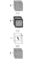
- FIG. 12 is an explanatory diagram for explaining a UI example according to the present embodiment. It is assumed that the virtual object 80A is a default display. When the prediction accuracy related to the movement of the virtual object 80A in the field of view decreases, the information processing apparatus 1 draws and superimposes a circle 82 of a size covering the virtual object, thereby drawing the virtual object 80B whose boundary is ambiguous. . It is desirable that the circle 82 has a lower transmittance toward the outer edge and a higher transmittance toward the center. In this case, as shown in the virtual object 80B, a display that is more ambiguous as the boundary is realized. When the prediction accuracy is restored, the information processing apparatus 1 redraws the virtual object 80C for which the application of the mask process is stopped.
- the information processing apparatus 1 may change the drawing method of the virtual object according to a factor with low prediction accuracy. For example, when the factor with low prediction accuracy is caused by the movement of the viewpoint (for example, the viewpoint has moved greatly), the information processing apparatus 1 hides the virtual object. On the other hand, when the factor with low prediction accuracy is caused by the movement of the real object (for example, the real object has moved greatly), the information processing apparatus 1 applies motion blur processing to the virtual object.
- the factor with low prediction accuracy is caused by the movement of the real object (for example, the real object has moved greatly
- the information processing apparatus 1 applies motion blur processing to the virtual object.
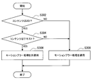
- FIG. 13 a flow of processing relating to a change in the drawing method in accordance with the accuracy reduction factor will be described.
- FIG. 13 is a flowchart showing an example of the flow of the virtual object display control process executed in the information processing apparatus 1 according to the present embodiment. Since the processing related to steps S202 to S216 is the same as the processing related to S102 to S116 described above with reference to FIG. 6, detailed description thereof will be omitted here.
- step S214 when it is determined that the prediction accuracy is low (step S214 / NO), the prediction accuracy estimation unit 500 estimates a factor with low prediction accuracy (step S218).
- step S220 When it is estimated that the factor with low prediction accuracy is that the viewpoint is moving greatly (step S220 / YES), the output control unit 600 hides the virtual object (step S222). On the other hand, when it is estimated that the cause of low prediction accuracy is that the real object is moving greatly and the viewpoint is not moving significantly (step S220 / NO), the output control unit 600 Motion blur processing is applied to the virtual object (step S224).
- step S226 / NO the process returns to step S202 again.
- step S226 / YES the process ends.
- the information processing apparatus 1 can control display of a virtual object based on various information.
- the information processing apparatus 1 can control the display of the virtual object based on information about the user, information about the virtual object, information about the real object, information about the environment, information about the information processing apparatus 1, or the like.
- gazing point line of sight or focus
- action recognition result stationary, walking, running, stair climbing, car driving, sport type
- moving speed biological information
- biological information heart rate, body temperature, sweating, blood pressure, Sweating, pulse, breathing, blink, eye movement, gaze time, pupil size, blood pressure, brain wave, body movement, body position, skin temperature, skin electrical resistance, MV (microvibration), myoelectric potential, SPO2 (in blood) Oxygen saturation)
- emotion estimation results feeling emotional
- user posture user position
- user settings manual input
- Information about virtual objects includes, for example, display size, display position, display orientation, display animation mode (movement speed, movement direction, trajectory, update frequency), content attributes (type, importance, priority, application) Type (browser, map, mailer, IME, SNS)), resolution, color, and the like.
- Examples of information related to information related to real objects include the type, shape, position, orientation, material, color, and the like of the real object.
- Information on the environment includes background (important information, background color), illuminance, location (indoor, outdoor, situation (geofence), behavior history (whether you are in a familiar place), surroundings (others, cars, etc.) Presence, density), time, altitude, temperature, wind direction, air volume, and the like.
- Information regarding the information processing apparatus 1 includes display resolution, display method, presence / absence of sensor, ID, remaining battery capacity, battery capacity, presence / absence of external storage medium slot, communication method, acoustic characteristics, imager characteristics, 3D shooting performance, 3D Display performance, device posture, device position, and the like.
- the information processing apparatus 1 is realized as an HMD
- the information regarding the information processing apparatus 1 may include an HMD system.
- the information related to the information processing apparatus 1 may include a wearable device wearing state (wearing, non-wearing, wearing location), a wearing position, and the like.
- FIG. 14 is a flowchart illustrating an example of the flow of a virtual object display control process executed in the information processing apparatus 1 according to the present embodiment.
- step S306 when the content is two-dimensional and text (step S302 / YES and step S304 / YES), the output control unit 600 does not apply motion blur processing to the virtual object (step S306). This is because text becomes difficult to read when motion blur processing is applied.
- step S308 when the content is not two-dimensional or text (step S302 / NO or step S304 / NO), the output control unit 600 applies motion blur processing to the virtual object (step S308).
- the information processing apparatus 1 for example, the output control unit 600
- the display of the virtual object may be changed.
- the content of the virtual object is three-dimensional.
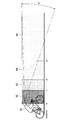
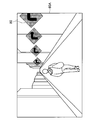
- FIG. 15 is an explanatory diagram for explaining a UI example according to the present embodiment.
- a situation is assumed in which a virtual object is displayed in a field of view 91 in front of a user 90 riding a bicycle.
- the space in front of 90 is divided into a space 92 whose distance from the user is ⁇ , a space 93 from ⁇ to ⁇ , a space 94 from ⁇ to ⁇ , and a space 95 greater than ⁇ .
- the values of ⁇ , ⁇ , and ⁇ may be predetermined values, or may vary depending on, for example, the moving speed of the user.
- the information processing apparatus 1 can switch the drawing method to be applied depending on which space the display position of the virtual object belongs to.
- FIG. 15 is an explanatory diagram for explaining a UI example according to the present embodiment.
- FIG. 16 is a flowchart illustrating an example of the flow of a virtual object display control process executed in the information processing apparatus 1 according to the present embodiment.
- step S404 when the distance from the user to the display position of the virtual object exceeds ⁇ (step S402 / YES), the output control unit 600 applies motion blur processing or mask processing to the virtual object (step S404). ).
- the output control unit 600 applies alpha fade processing or wire processing to the virtual object. Is applied (step S408).
- step S406 / NO when the distance from the user to the display position of the virtual object is less than ⁇ (step S406 / NO) and exceeds ⁇ (step S410 / YES), the output control unit 600 applies high-speed scroll processing to the virtual object. (Step S412).
- the high-speed scroll process will be described in detail later.
- step S410 when the distance from the user to the display position of the virtual object is less than ⁇ (step S410 / NO and step S414 / YES), the output control unit 600 hides the virtual object (step S416).
- step S414 / NO when the distance from the user to the display position of the virtual object is not less than ⁇ (step S414 / NO), the output control unit 600 applies scale adjustment, brightness value adjustment, color change, and the like to the virtual object. This step can be executed when there is no distance, for example, when a virtual object is pasted on the display surface.
- FIGS. 17 and 18 are explanatory diagrams for describing an example UI according to the present embodiment.
- FIG. 17 shows a UI example to which high-speed scroll processing is not applied.
- the real space image 60A shown in FIG. 17 includes a person walking in front of the user who is walking, and a plurality of signs 80 are displayed at equal intervals as virtual objects. Assuming that the position of the sign 80 in the real space is fixed, when the user moves, the position of the sign 80 on the display surface changes according to the amount of movement. In the example shown in FIG. 17, since the user is moving in parallel with the sign 80 arranged in the depth direction of the real space image 60A, the sign 80 moves toward the image frame according to the user's movement, and the image is displayed. It disappears when it goes out of the frame. Therefore, in the real space image 60A, only a part of the image frame is displayed for the sign 80 that overlaps the image frame.
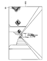
- FIG. 18 shows an example of a UI to which high-speed scroll processing is applied.
- the real space image 60B shown in FIG. 18 includes a person who travels by bicycle in front of the user who is traveling by bicycle, and a plurality of signs 80 are displayed as in FIG.
- the moving speed of the user is faster than in the example shown in FIG. 17, the moving speed of the sign 80 toward the image frame is faster. Therefore, in the example illustrated in FIG. 18, when the sign 80 moves toward the image frame, the sign 80 is accelerated (intervals are opened) as it approaches the image frame and is displayed in an ambiguous manner. That is, the sign 80 is accelerated as the user approaches the sign 80.
- the sign 80 close to the image frame is quickly removed from the image frame, the time for displaying only a part of the image frame for the sign 80 overlapping the image frame is shortened.
- a virtual object is accelerated and vaguely displayed as it gets closer to the user and closer to the image frame, from the viewpoint that a far object is slower and a closer object is faster. This has the effect of reducing the unnatural display of the virtual object.
- the sign 80 accelerates the position of the sign 80 in the real space may be temporarily changed.
- the information processing apparatus 1 may display a setting screen related to display of a virtual object.
- the user can set the strength of motion blur, the acceleration of high-speed scroll processing, and the like using the setting UI.
- FIG. 19 to FIG. 22 a flow of processing related to display of a setting UI and a UI example will be described.
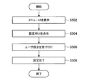
- FIG. 19 is a flowchart showing an example of the flow of the virtual object display control process executed in the information processing apparatus 1 according to the present embodiment.
- the output control unit 600 displays a menu UI (step S502).
- An example of the menu UI is shown in FIG.
- FIG. 20 is an explanatory diagram for describing a UI example according to the present embodiment.
- menu items 80A to 80C are displayed as virtual objects in the real space image 60A.
- Menu item 80A is a menu item for movie playback.
- the menu item 80B is a menu item for display setting.
- the menu item 80C is a menu item for game execution.
- the output control unit 600 displays a setting UI (step S504). Then, the information processing apparatus 1 (for example, the real object recognition unit 120 or the viewpoint detection unit 200) receives the user setting (step S506) and completes the setting (step S508).
- the information processing apparatus 1 for example, the real object recognition unit 120 or the viewpoint detection unit 200
- receives the user setting step S506
- completes the setting step S508.
- FIG. 21 is an explanatory diagram for explaining a UI example according to the present embodiment.
- icons 80D to 80F are displayed as setting UIs for setting the range or strength to which the motion blur is applied. These icons are assumed to be fixed in the real space around the user.
- the motion blur intensity is 6.0.
- the intensity of motion blur is 6.2.
- icon 80F is selected, the intensity of motion blur is 6.4.
- the user selects the icon and sets the strength of motion blur by shaking his / her head left and right to position one of the icons 80D to 80F in front or directing his / her line of sight toward one of the icons 80D to 80F. can do.
- FIG. 22 is an explanatory diagram for explaining a UI example according to the present embodiment.
- icons 80G to 80I are displayed as setting UIs for setting the range or strength to which the motion blur is applied. These icons are assumed to be fixed in the real space around the user.
- the icon 80H indicates the setting value of the motion blur intensity.
- the motion blur intensity setting value in the icon 80H decreases.
- the icon 80I is selected, the motion blur intensity setting value in the icon 80H increases.
- the icon 80H is selected, the setting of the motion blur intensity is completed.
- the user selects an icon and sets the intensity of motion blur by shaking his / her head left and right to position one of the icons 80G to 80I in front or directing his / her line of sight toward one of the icons 80G to 80I. can do.
- FIG. 23 is a block diagram illustrating an example of a logical configuration of the HMD 1 according to the present embodiment. As shown in FIG. 23, the HMD 1 according to the present embodiment has more detailed components based on the configuration of the information processing apparatus 1 described above with reference to FIG. Hereinafter, each component will be described in detail.
- the real object detection unit 100 includes a camera 102.
- the camera 102 is a device that captures an image of real space.
- the camera 102 is installed so as to capture the user's field of view (front) when the HMD 1 is mounted.
- the camera 102 provides the captured image and the time stamp of the imaging time to the real object recognition processing unit 122.
- the real object recognition unit 120 includes a real object recognition processing unit 122 and a real object dictionary 124.
- the real object recognition processing unit 122 compares the real space information acquired by the camera 102 with the characteristics of the real object registered in the real object dictionary 124 to find and recognize the real object to be superimposed.
- the real object recognition processing unit 122 provides the real object prediction processing unit 142 with the position or orientation of the recognized real object and the time stamp given to the information used for recognition.
- the real object dictionary 124 is data in which features of real objects to be superimposed are recorded.
- the real object dictionary 124 can include feature point information obtained when a real object is photographed by the camera 102.
- the real object prediction unit 140 includes a real object prediction processing unit 142 and a real object recognition history 144.
- the real object prediction processing unit 142 refers to the position or posture of the real object recognized by the real object recognition processing unit 122 and the real object recognition history 144, and estimates the movement or posture change of the real object.
- Real object prediction processing unit 142 based on the estimation result to estimate the position or orientation of the real object in the display time T 2.
- the real object prediction processing unit 142 assumes that the time indicated by the time stamp provided from the real object recognition processing unit 122 is T 0 and that the time obtained by adding the delay ⁇ T output by the drawing delay detection unit 300 to T 0 is T 2. And make a prediction.
- the real object prediction processing unit 142 performs the prediction assuming that the real object performs a constant linear motion from T 0 to T 2 .
- the real object prediction processing unit 142 provides the predicted position or orientation of the real object and the time stamp of time T 0 used for the prediction to the in-view state prediction processing unit 402.
- the real object recognition history 144 is a history of the actual object position or orientation recognition results for the past several times provided from the real object recognition processing unit 122 and a time stamp associated therewith.
- the viewpoint detection unit 200 includes an acceleration sensor 202 and a gyro sensor 204.
- the acceleration sensor 202 is a sensor that acquires acceleration applied to the HMD 1 in order to detect viewpoint movement.
- the acceleration sensor 202 provides the acquired acceleration and the time stamp of the acquired time to the viewpoint recognition processing unit 222.
- the gyro sensor 204 is a sensor that acquires the angular velocity of the HMD 1.
- the gyro sensor 204 provides the acquired angular velocity and the time stamp of the acquired time to the viewpoint recognition processing unit 222.
- the viewpoint recognition unit 220 includes a viewpoint recognition processing unit 222.
- the viewpoint recognition processing unit 222 recognizes the position or orientation of the user's viewpoint based on the acceleration and angular velocity acquired by the acceleration sensor 202 and the gyro sensor 204.
- the viewpoint recognition processing unit 222 provides the recognition result and the time stamp given to the sensor information used for recognition to the viewpoint prediction processing unit 242.
- the viewpoint prediction unit 240 includes a viewpoint prediction processing unit 242 and a viewpoint recognition history 244.
- the viewpoint prediction processing unit 242 refers to the recognition result of the viewpoint recognition processing unit 222 and the viewpoint recognition history 244 to estimate a change in the position or orientation (orientation) of the viewpoint.
- Viewpoint prediction processing unit 242 based on the estimation result to estimate the position or orientation of the viewpoint at the time T 2.
- Viewpoint prediction processing unit 242 the time indicated by the time stamp provided from the viewpoint recognition processing section 222 and T 0, the time delay ⁇ T is added to T 0 the drawing delay detecting unit 300, and outputs the assumed T 2 Make a prediction.
- the viewpoint prediction processing unit 242 performs the prediction assuming that the viewpoint performs a constant velocity linear motion from T 0 to T 2 .
- the viewpoint prediction processing unit 242 provides the predicted position or orientation of the viewpoint and the time stamp of time T 0 used for the prediction to the in-view state prediction processing unit 402.
- the viewpoint recognition history 244 is the history of the recognition of the position or posture of the viewpoint for the past several times provided from the viewpoint recognition processing unit 222 and the time stamp associated therewith.
- Drawing the delay detection unit 300 detects whether the display time T 2, is the extent to which the delay with respect to the detection time T 0.
- the drawing delay detection unit 300 includes a time stamp when each of the real object detection unit 100 and the viewpoint detection unit 200 acquires real space information, and a time when the display controller 704 outputs an image based on the acquired information. The stamps are compared, and the difference is detected as a delay ( ⁇ T).
- the drawing delay detection unit 300 provides the detected delay to each of the real object prediction unit 140, the viewpoint prediction unit 240, and the in-view state prediction unit 400.
- the visual field state prediction unit 400 includes a visual field state prediction processing unit 402.
- the in-view state prediction processing unit 402 is based on the position or orientation of the real object after movement predicted by the real object prediction processing unit 142 and the position or posture of the viewpoint after movement predicted by the viewpoint prediction processing unit 242. Predict the state inside. Specifically, the visual field state prediction processing unit 402 determines in which position in the visual field and in which posture the real object to be superimposed with the virtual object exists at the image output timing (display time T 2 ) of the display controller 704. Predict.
- the prediction accuracy estimation unit 500 includes a prediction accuracy estimation processing unit 502, a prediction related information history 504, and an accuracy reduction factor estimation unit 506.
- the prediction accuracy estimation processing unit 502 provides information indicating the accuracy of prediction performed by the in-view state prediction processing unit 402 to the application 604.
- the prediction related information history 504 is a log of information used by the prediction accuracy estimation processing unit 502 at the time of estimation.
- the prediction related information history 504 is output from the prediction result of the in-field state prediction processing unit 402, the position or orientation of the real object or viewpoint used for prediction, the time stamp associated with each, and the drawing delay detection unit 300.
- a delay ⁇ T may be included.
- the accuracy decrease factor estimation unit 506 estimates the factor that the prediction accuracy has decreased and provides information indicating the estimation result to the application 604.
- the accuracy reduction factor estimation unit 506 refers to the prediction related information history 504, and the prediction accuracy is low because the real object moves irregularly, and the prediction accuracy is low because the user moves the head greatly and the viewpoint moves. Factors such as low are estimated.
- the output control unit 600 includes a GPU 602 and an application 604.
- the GPU 602 is a processing device that executes various operations related to image processing.
- the GPU 602 performs drawing based on an instruction from the application 604 and provides a display result to the display controller 704.
- the application 604 is software that provides a main function used by the user.
- the application 604 provides a UI that displays a virtual object superimposed on a real object in the real space as one of the functions.
- the application 604 determines what virtual object is to be rendered in what expression and where, and performs rendering by issuing a rendering command to the GPU 602.
- the application 604 changes the display content of the virtual object according to the prediction result of the prediction accuracy estimation processing unit 502 and the estimation result of the accuracy lowering factor estimation unit 506.
- the display unit 700 includes a display 702 and a display controller 704.
- the display 702 is a device that receives an output signal of the display controller 704 and displays an image.
- the display controller 704 is a device that receives a drawing result of the GPU 602 and outputs a video signal to the display 702. When the display controller 704 outputs a signal, the display controller 704 outputs information indicating the time of the output timing as a time stamp and provides it to the drawing delay detection unit 300.
- the HMD 1 may take a configuration other than the configuration example described above. An example will be described below.
- FIG. 24 is a block diagram illustrating an example of a logical configuration of the HMD 1 according to the present embodiment. As illustrated in FIG. 24, the HMD 1 according to the present configuration example is different from the configuration example illustrated in FIG. 23 with respect to the real object detection unit 100. Hereinafter, differences will be described.
- the real object detection unit 100 includes a camera 102 and a depth sensor 104.
- the depth sensor 104 is a sensor that acquires depth information.
- the depth sensor 104 is installed so as to acquire depth information in the same direction as the camera 102.
- the depth sensor 104 provides the acquired depth information and the time stamp of the acquired time to the real object recognition processing unit 122. Note that the functions of the camera 102 and the depth sensor 104 may be realized as a stereo camera.
- the real object recognition processing unit 122 compares the real space information acquired by the camera 102 and the depth sensor 104 with the characteristics of the real object registered in the real object dictionary 124 to find and recognize the real object to be superimposed. To do.
- the real object dictionary 124 can include information on feature points obtained when the real object is photographed by the camera 102 and information on the three-dimensional shape of the real object.
- FIG. 25 is a block diagram illustrating an example of a logical configuration of the HMD 1 according to the present embodiment. As shown in FIG. 25, the HMD 1 according to this configuration example is different from the configuration example shown in FIG. Hereinafter, differences will be described.
- the viewpoint detection unit 200 includes an acceleration sensor 202, a gyro sensor 204, and a camera 206.
- the camera 206 is installed with the user's eyes as the imaging range.
- the camera 206 provides the captured image and the time stamp of the acquired time to the viewpoint recognition processing unit 222.
- the viewpoint recognition processing unit 222 recognizes the position or orientation of the user's viewpoint based on the acceleration, angular velocity, and captured image acquired by the acceleration sensor 202, the gyro sensor 204, and the camera 206.
- FIG. 26 is a block diagram illustrating an example of a logical configuration of the information processing apparatus 1 according to the present modification. As illustrated in FIG. 26, the information processing apparatus 1 according to the present modification includes a time control unit 800 in addition to the components illustrated in FIG.
- the time control unit 800 has a function of controlling the length of the time lag according to the prediction accuracy. As described above, when the time lag is short, an improvement in prediction accuracy is expected. Therefore, the time control unit 800 shortens the time lag when the prediction accuracy is not sufficient, and lengthens the time lag when the prediction accuracy is excessive. Thereby, the time control unit 800 can maintain a desired prediction accuracy.
- the time control unit 800 can control the length of the time lag by increasing or decreasing the operation speed of, for example, a CPU, GPU, or sensor. Of course, the time control unit 800 may control the length of the time lag without changing the operation speed.
- the time control unit 800 may control the time lag length by controlling the power consumption of the information processing apparatus 1.
- the time control unit 800 controls power consumption in a range where the prediction accuracy estimated by the prediction accuracy estimation unit 500 exceeds a threshold value.
- the time control unit 800 increases the power consumption by increasing the power consumption when the prediction accuracy is below the threshold, and decreases the operation speed by decreasing the power consumption when the prediction accuracy exceeds the threshold. Thereby, it is possible to maintain the prediction accuracy while preventing the power consumption from unnecessarily increasing.
- the information processing apparatus 1 (for example, the output control unit 600) relates to, for example, a virtual object that is displayed in a region that is focused on by the user or a virtual object that is focused on. Processing may be prioritized over others. For example, the information processing apparatus 1 may reduce the processing speed (frame rate or the like) of processing related to other virtual objects. Thereby, power saving is implement
- the information processing apparatus 1 may have a normal mode and a power saving mode as operation modes. Specifically, in the normal mode, the information processing apparatus 1 increases the power consumption and increases the operation speed. Further, in the power saving mode, the information processing apparatus 1 reduces the power consumption to reduce the operation speed. For example, the information processing apparatus 1 may automatically switch operations such as operating in a normal mode because it is easy to charge indoors and operating in a power saving mode if outdoor.
- FIG. 27 is a block diagram illustrating an example of a hardware configuration of the information processing apparatus according to the present embodiment.
- the information processing apparatus 900 illustrated in FIG. 27 can realize, for example, the information processing apparatus 1 illustrated in FIGS. 5 and 23 to 26, respectively.
- Information processing by the information processing apparatus 1 according to the present embodiment is realized by cooperation between software and hardware described below.
- the information processing apparatus 900 includes a CPU (Central Processing Unit) 901, a ROM (Read Only Memory) 902, a RAM (Random Access Memory) 903, and a host bus 904a.
- the information processing apparatus 900 includes a bridge 904, an external bus 904b, an interface 905, an input device 906, an output device 907, a storage device 908, a drive 909, a connection port 911, and a communication device 913.
- the information processing apparatus 900 may include a processing circuit such as a DSP or an ASIC in place of or in addition to the CPU 901.
- the CPU 901 functions as an arithmetic processing unit and a control unit, and controls the overall operation in the information processing apparatus 900 according to various programs. Further, the CPU 901 may be a microprocessor.
- the ROM 902 stores programs used by the CPU 901, calculation parameters, and the like.
- the RAM 903 temporarily stores programs used in the execution of the CPU 901, parameters that change as appropriate during the execution, and the like.
- the CPU 901 includes, for example, the real object recognition unit 120, the real object prediction unit 140, the viewpoint recognition unit 220, the viewpoint prediction unit 240, the drawing delay detection unit 300, and the in-field state prediction unit illustrated in FIGS. 5 and 23 to 26, respectively. 400, the prediction accuracy estimation unit 500, and the output control unit 600 may be formed. Further, the CPU 901 can form, for example, the time control unit 800 shown in FIG.
- the CPU 901, ROM 902, and RAM 903 are connected to each other by a host bus 904a including a CPU bus.
- the host bus 904 a is connected to an external bus 904 b such as a PCI (Peripheral Component Interconnect / Interface) bus via a bridge 904.
- an external bus 904 b such as a PCI (Peripheral Component Interconnect / Interface) bus
- PCI Peripheral Component Interconnect / Interface
- the host bus 904a, the bridge 904, and the external bus 904b do not necessarily have to be configured separately, and these functions may be mounted on one bus.
- the input device 906 is realized by a device in which information is input by the user, such as a mouse, a keyboard, a touch panel, a button, a microphone, a switch, and a lever.
- the input device 906 may be, for example, a remote control device using infrared rays or other radio waves, or may be an external connection device such as a mobile phone or a PDA that supports the operation of the information processing device 900.
- the input device 906 may include, for example, an input control circuit that generates an input signal based on information input by the user using the above-described input means and outputs the input signal to the CPU 901.
- a user of the information processing apparatus 900 can input various data and instruct a processing operation to the information processing apparatus 900 by operating the input device 906.
- the input device 906 can be formed by a device that detects information about the user.
- the input device 906 includes various sensors such as an image sensor (for example, a camera), a depth sensor (for example, a stereo camera), an acceleration sensor, a gyro sensor, a geomagnetic sensor, an optical sensor, a sound sensor, a distance sensor, and a force sensor. Can be included.
- the input device 906 includes information related to the information processing device 900 state, such as the posture and movement speed of the information processing device 900, and information related to the surrounding environment of the information processing device 900, such as brightness and noise around the information processing device 900. May be obtained.
- the input device 906 receives a GNSS signal from a GNSS (Global Navigation Satellite System) satellite (for example, a GPS signal from a GPS (Global Positioning System) satellite) and receives position information including the latitude, longitude, and altitude of the device.
- GNSS Global Navigation Satellite System
- a GNSS module to measure may be included.
- the input device 906 may detect the position by transmission / reception with Wi-Fi (registered trademark), a mobile phone / PHS / smartphone, or the like, or near field communication.
- Wi-Fi registered trademark
- a mobile phone / PHS / smartphone or the like, or near field communication.
- the input device 906 can form, for example, the real object detection unit 100 and the viewpoint detection unit 200 shown in FIGS. 5 and 23 to 26, respectively.
- the output device 907 is formed of a device that can notify the user of the acquired information visually or audibly.
- Examples of such devices include CRT display devices, liquid crystal display devices, plasma display devices, EL display devices, display devices such as laser projectors, LED projectors and lamps, audio output devices such as speakers and headphones, printer devices, and the like.
- the output device 907 outputs results obtained by various processes performed by the information processing device 900.
- the display device visually displays results obtained by various processes performed by the information processing device 900 in various formats such as text, images, tables, and graphs.
- the audio output device converts an audio signal composed of reproduced audio data, acoustic data, and the like into an analog signal and outputs it aurally.
- the display device can form the display unit 700 shown in FIGS. 5 and 23 to 26, for example.
- the storage device 908 is a data storage device formed as an example of a storage unit of the information processing device 900.
- the storage apparatus 908 is realized by, for example, a magnetic storage device such as an HDD, a semiconductor storage device, an optical storage device, a magneto-optical storage device, or the like.
- the storage device 908 may include a storage medium, a recording device that records data on the storage medium, a reading device that reads data from the storage medium, a deletion device that deletes data recorded on the storage medium, and the like.
- the storage device 908 stores programs executed by the CPU 901, various data, various data acquired from the outside, and the like.
- the drive 909 is a storage medium reader / writer, and is built in or externally attached to the information processing apparatus 900.
- the drive 909 reads information recorded on a removable storage medium such as a magnetic disk, an optical disk, a magneto-optical disk, or a semiconductor memory, and outputs the information to the RAM 903.
- the drive 909 can also write information to a removable storage medium.
- connection port 911 is an interface connected to an external device, and is a connection port with an external device capable of transmitting data by USB (Universal Serial Bus), for example.
- USB Universal Serial Bus
- the communication device 913 is a communication interface formed by a communication device or the like for connecting to the network 920, for example.
- the communication device 913 is, for example, a communication card for wired or wireless LAN (Local Area Network), LTE (Long Term Evolution), Bluetooth (registered trademark), or WUSB (Wireless USB).
- the communication device 913 may be a router for optical communication, a router for ADSL (Asymmetric Digital Subscriber Line), a modem for various communication, or the like.
- the communication device 913 can transmit and receive signals and the like according to a predetermined protocol such as TCP / IP, for example, with the Internet and other communication devices.
- the network 920 is a wired or wireless transmission path for information transmitted from a device connected to the network 920.
- the network 920 may include a public line network such as the Internet, a telephone line network, a satellite communication network, various LANs including Ethernet (registered trademark), a WAN (Wide Area Network), and the like.
- the network 920 may include a dedicated line network such as an IP-VPN (Internet Protocol-Virtual Private Network).
- IP-VPN Internet Protocol-Virtual Private Network
- each of the above components may be realized using a general-purpose member, or may be realized by hardware specialized for the function of each component. Therefore, it is possible to change the hardware configuration to be used as appropriate according to the technical level at the time of carrying out this embodiment.
- a computer program for realizing each function of the information processing apparatus 900 according to the present embodiment as described above can be produced and mounted on a PC or the like.
- a computer-readable recording medium storing such a computer program can be provided.
- the recording medium is, for example, a magnetic disk, an optical disk, a magneto-optical disk, a flash memory, or the like.
- the above computer program may be distributed via a network, for example, without using a recording medium.
- the information processing apparatus 1 estimates the prediction accuracy related to the prediction of the position or orientation of the real object displayed on the display unit 700, and displays the virtual object corresponding to the real object based on the estimation result.
- the information processing apparatus 1 makes the display of the virtual object clearer as the prediction accuracy is higher, and makes the display of the virtual object ambiguous as the prediction accuracy is lower. Thereby, even if it is a case where a shift
- the information processing apparatus 1 controls the position or orientation of the virtual object, and alternatively, the position and orientation are described.
- the information processing apparatus 1 may control both the position and the posture. In that case, in the above description, “or” described regarding the positions and orientations of the real object and the virtual object may be replaced with “and”.
- a prediction accuracy estimation unit that estimates the prediction accuracy related to the prediction of the position or orientation of the real object; Based on the estimation result by the prediction accuracy estimation unit, an output control unit that outputs information for causing the display unit to display a virtual object corresponding to the real object;
- An information processing apparatus comprising: (2) The output control unit displays the virtual object so that the relevance with the corresponding real object is higher as the prediction accuracy is higher, and the relevance with the corresponding real object is lower as the prediction accuracy is lower.
- the information processing apparatus according to (1) wherein information for displaying the virtual object is output.
- the information processing apparatus outputs information for causing the display of the virtual object to be displayed in accordance with a factor with low prediction accuracy. .
- the output control unit outputs information for making the virtual object non-display when the factor is caused by movement of a viewpoint.
- the prediction accuracy estimation unit estimates the prediction accuracy based on at least one of the magnitude or regularity of a motion of an object used for the prediction of the position or orientation.
- the information processing apparatus according to (11), wherein the object is the real object. (13) The information processing apparatus according to (11) or (12), wherein the object is the display unit. (14) The information processing apparatus according to any one of (11) to (13), wherein the object is a user's eye. (15) The prediction of the position or orientation is a prediction related to a time from a time when information for prediction is detected to a time when the virtual object is displayed, according to any one of (1) to (14). The information processing apparatus described. (16) The information processing apparatus according to (15), further including a time control unit that controls the length of the time according to the prediction accuracy. (17) The information processing apparatus according to (16), wherein the time control unit controls the length of the time by controlling power consumption of the information processing apparatus.
Landscapes
- Engineering & Computer Science (AREA)
- Theoretical Computer Science (AREA)
- Physics & Mathematics (AREA)
- General Physics & Mathematics (AREA)
- General Engineering & Computer Science (AREA)
- Multimedia (AREA)
- Computer Vision & Pattern Recognition (AREA)
- Computer Hardware Design (AREA)
- Human Computer Interaction (AREA)
- Software Systems (AREA)
- General Health & Medical Sciences (AREA)
- Artificial Intelligence (AREA)
- Evolutionary Computation (AREA)
- Health & Medical Sciences (AREA)
- Data Mining & Analysis (AREA)
- Computer Graphics (AREA)
- Life Sciences & Earth Sciences (AREA)
- Bioinformatics & Computational Biology (AREA)
- Evolutionary Biology (AREA)
- Computing Systems (AREA)
- Ophthalmology & Optometry (AREA)
- Bioinformatics & Cheminformatics (AREA)
- Medical Informatics (AREA)
- Databases & Information Systems (AREA)
- Optics & Photonics (AREA)
- User Interface Of Digital Computer (AREA)
- Processing Or Creating Images (AREA)
- Controls And Circuits For Display Device (AREA)
- Image Analysis (AREA)
Priority Applications (4)
| Application Number | Priority Date | Filing Date | Title |
|---|---|---|---|
| CN201680052515.3A CN108027652B (zh) | 2015-09-16 | 2016-06-14 | 信息处理设备、信息处理方法以及记录介质 |
| JP2017539717A JP6844542B2 (ja) | 2015-09-16 | 2016-06-14 | 情報処理装置、情報処理方法及びプログラム |
| EP16846051.7A EP3352050A4 (en) | 2015-09-16 | 2016-06-14 | INFORMATION PROCESSING DEVICE, INFORMATION PROCESSING PROCESS AND PROGRAM |
| US15/752,312 US10977774B2 (en) | 2015-09-16 | 2016-06-14 | Information processing apparatus, information processing method, and program for estimating prediction accuracy |
Applications Claiming Priority (2)
| Application Number | Priority Date | Filing Date | Title |
|---|---|---|---|
| JP2015-182380 | 2015-09-16 | ||
| JP2015182380 | 2015-09-16 |
Publications (1)
| Publication Number | Publication Date |
|---|---|
| WO2017047178A1 true WO2017047178A1 (ja) | 2017-03-23 |
Family
ID=58288617
Family Applications (1)
| Application Number | Title | Priority Date | Filing Date |
|---|---|---|---|
| PCT/JP2016/067709 WO2017047178A1 (ja) | 2015-09-16 | 2016-06-14 | 情報処理装置、情報処理方法及びプログラム |
Country Status (5)
| Country | Link |
|---|---|
| US (1) | US10977774B2 (zh) |
| EP (1) | EP3352050A4 (zh) |
| JP (1) | JP6844542B2 (zh) |
| CN (1) | CN108027652B (zh) |
| WO (1) | WO2017047178A1 (zh) |
Cited By (19)
| Publication number | Priority date | Publication date | Assignee | Title |
|---|---|---|---|---|
| WO2018225187A1 (ja) * | 2017-06-07 | 2018-12-13 | 株式会社ソニー・インタラクティブエンタテインメント | 情報処理システム、情報処理装置、サーバ装置、画像提供方法および画像生成方法 |
| WO2019026713A1 (ja) * | 2017-08-04 | 2019-02-07 | ソニー株式会社 | 情報処理装置、情報処理方法、およびプログラム |
| JP2019047215A (ja) * | 2017-08-30 | 2019-03-22 | シナノケンシ株式会社 | 映像解析方法 |
| WO2019072481A1 (de) * | 2017-10-09 | 2019-04-18 | Audi Ag | Verfahren zum betrieb einer anzeigeeinrichtung in einem kraftfahrzeug |
| WO2019087513A1 (ja) * | 2017-10-31 | 2019-05-09 | ソニー株式会社 | 情報処理装置、情報処理方法およびプログラム |
| WO2019138515A1 (ja) * | 2018-01-11 | 2019-07-18 | 株式会社ニコン・エシロール | 画像作成装置、眼鏡レンズ選択システム、画像作成方法およびプログラム |
| WO2019149625A1 (de) * | 2018-02-05 | 2019-08-08 | Audi Ag | Verfahren zum überlagern eines virtuellen graphischen objekts über eine reale umgebung mittels einer ar-anzeigeeinrichtung für augmented-reality sowie kraftfahrzeug |
| WO2019187801A1 (ja) * | 2018-03-30 | 2019-10-03 | ソニー株式会社 | 情報処理装置、情報処理方法、および、プログラム |
| WO2020031795A1 (ja) * | 2018-08-07 | 2020-02-13 | ソニー株式会社 | 情報処理装置、情報処理方法およびプログラム |
| JP2020071394A (ja) * | 2018-10-31 | 2020-05-07 | キヤノン株式会社 | 情報処理装置、情報処理方法及びプログラム |
| EP3667625A4 (en) * | 2017-08-09 | 2020-08-12 | Sony Corporation | INFORMATION PROCESSING DEVICE, INFORMATION PROCESSING PROCESS AND PROGRAM |
| US11048465B2 (en) | 2018-09-18 | 2021-06-29 | Canon Kabushiki Kaisha | Imaging display device, wearable device, and imaging display system |
| WO2022172692A1 (ja) * | 2021-02-12 | 2022-08-18 | ソニーグループ株式会社 | 画像処理装置、画像処理方法、画像処理システム |
| WO2022190970A1 (ja) * | 2021-03-08 | 2022-09-15 | ソニーグループ株式会社 | 情報処理装置、情報処理方法、プログラム、及び、情報処理システム |
| DE112021003465T5 (de) | 2020-06-30 | 2023-05-17 | Sony Group Corporation | Informationsprozessor, informationsverarbeitungsverfahren und speichermedium |
| WO2023140110A1 (ja) * | 2022-01-20 | 2023-07-27 | ソニーグループ株式会社 | 端末装置、位置姿勢推定方法、およびプログラム |
| US11755105B2 (en) | 2018-09-20 | 2023-09-12 | Fujifilm Corporation | Information processing apparatus, information processing system, information processing method, and program |
| JP7379734B2 (ja) | 2018-06-25 | 2023-11-14 | マクセル株式会社 | ヘッドマウントディスプレイ |
| JP7418075B2 (ja) | 2018-09-18 | 2024-01-19 | キヤノン株式会社 | 撮像表示装置、ウェアラブルデバイスおよび撮像表示システム |
Families Citing this family (15)
| Publication number | Priority date | Publication date | Assignee | Title |
|---|---|---|---|---|
| CN107918955A (zh) * | 2017-11-15 | 2018-04-17 | 百度在线网络技术(北京)有限公司 | 增强现实方法和装置 |
| KR102521557B1 (ko) * | 2018-01-04 | 2023-04-14 | 삼성전자주식회사 | 스크롤 입력에 기반하여 이미지 표시를 제어하는 전자 장치 및 방법 |
| WO2019150781A1 (ja) * | 2018-01-30 | 2019-08-08 | ソニー株式会社 | 情報処理装置、情報処理方法およびプログラム |
| WO2019155735A1 (ja) * | 2018-02-07 | 2019-08-15 | ソニー株式会社 | 情報処理装置、情報処理方法及びプログラム |
| JP7400721B2 (ja) * | 2018-08-29 | 2023-12-19 | ソニーグループ株式会社 | 情報処理装置、情報処理方法及びプログラム |
| WO2020071029A1 (ja) * | 2018-10-04 | 2020-04-09 | ソニー株式会社 | 情報処理装置、情報処理方法、及び記録媒体 |
| US10812771B1 (en) * | 2019-06-12 | 2020-10-20 | At&T Intellectual Property I, L.P. | Methods, systems, and devices for adjusting image content for streaming panoramic video content |
| US10699124B1 (en) * | 2019-09-09 | 2020-06-30 | Ar, Llc | Augmented reality content selection and display based on printed objects having security features |
| US11961294B2 (en) | 2019-09-09 | 2024-04-16 | Techinvest Company Limited | Augmented, virtual and mixed-reality content selection and display |
| EP4207088A4 (en) * | 2020-10-07 | 2024-03-06 | Samsung Electronics Co Ltd | AUGMENTED REALITY DISPLAY METHOD AND ELECTRONIC DEVICE FOR USING IT |
| CN112687222B (zh) * | 2020-12-28 | 2021-12-17 | 北京大学 | 基于脉冲信号的显示方法、装置、电子设备及介质 |
| CN117296082A (zh) * | 2021-05-20 | 2023-12-26 | 华为技术有限公司 | 一种图像处理方法及装置 |
| US11960345B2 (en) * | 2021-05-25 | 2024-04-16 | Samsung Electronics Co., Ltd. | System and method for controlling operational modes for XR devices for performance optimization |
| EP4369177A1 (en) * | 2021-07-31 | 2024-05-15 | Huawei Technologies Co., Ltd. | Display method, device and system |
| US11759711B2 (en) * | 2021-09-28 | 2023-09-19 | Sony Group Corporation | Method for quasi-random placement of virtual items in an extended reality (XR) space |
Citations (2)
| Publication number | Priority date | Publication date | Assignee | Title |
|---|---|---|---|---|
| JP2011221800A (ja) * | 2010-04-09 | 2011-11-04 | Toshiba Corp | 映像表示装置、映像表示方法及び映像表示プログラム |
| JP2012221250A (ja) * | 2011-04-08 | 2012-11-12 | Sony Corp | 画像処理装置、表示制御方法及びプログラム |
Family Cites Families (17)
| Publication number | Priority date | Publication date | Assignee | Title |
|---|---|---|---|---|
| JP3218730B2 (ja) * | 1992-10-19 | 2001-10-15 | 株式会社ニコン | 予測機能を有する焦点調節装置 |
| JP3745117B2 (ja) * | 1998-05-08 | 2006-02-15 | キヤノン株式会社 | 画像処理装置及び画像処理方法 |
| CN100478849C (zh) * | 2007-04-10 | 2009-04-15 | 南京航空航天大学 | 基于多加速度传感器的虚拟现实头盔防眩晕系统及方法 |
| JP5047090B2 (ja) * | 2008-07-31 | 2012-10-10 | キヤノン株式会社 | システム |
| JP2011258159A (ja) | 2010-06-11 | 2011-12-22 | Namco Bandai Games Inc | プログラム、情報記憶媒体及び画像生成システム |
| US9348141B2 (en) * | 2010-10-27 | 2016-05-24 | Microsoft Technology Licensing, Llc | Low-latency fusing of virtual and real content |
| KR101896026B1 (ko) * | 2011-11-08 | 2018-09-07 | 삼성전자주식회사 | 휴대 단말기에서 움직임 블러를 생성하는 장치 및 방법 |
| US20140176591A1 (en) * | 2012-12-26 | 2014-06-26 | Georg Klein | Low-latency fusing of color image data |
| WO2015030797A1 (en) * | 2013-08-30 | 2015-03-05 | Intel Corporation | Nausea and seizure detection, prediction, and mitigation for head-mounted displays |
| US9607409B2 (en) * | 2013-12-23 | 2017-03-28 | Empire Technology Development Llc | Suppression of real features in see-through display |
| US10565925B2 (en) * | 2014-02-07 | 2020-02-18 | Samsung Electronics Co., Ltd. | Full color display with intrinsic transparency |
| JP2015228050A (ja) * | 2014-05-30 | 2015-12-17 | ソニー株式会社 | 情報処理装置および情報処理方法 |
| CN104539929B (zh) * | 2015-01-20 | 2016-12-07 | 深圳威阿科技有限公司 | 带有运动预测的立体图像编码方法和编码装置 |
| KR101919077B1 (ko) * | 2017-08-24 | 2018-11-16 | 에스케이텔레콤 주식회사 | 증강 현실 표시 방법 및 장치 |
| US10425593B2 (en) * | 2017-10-19 | 2019-09-24 | Paypal, Inc. | Digital image filtering and post-capture processing using user specific data |
| US10375313B1 (en) * | 2018-05-07 | 2019-08-06 | Apple Inc. | Creative camera |
| US10482583B1 (en) * | 2018-05-10 | 2019-11-19 | Google Llc | Generating and displaying blur in images |
-
2016
- 2016-06-14 EP EP16846051.7A patent/EP3352050A4/en not_active Withdrawn
- 2016-06-14 US US15/752,312 patent/US10977774B2/en active Active
- 2016-06-14 CN CN201680052515.3A patent/CN108027652B/zh active Active
- 2016-06-14 WO PCT/JP2016/067709 patent/WO2017047178A1/ja active Application Filing
- 2016-06-14 JP JP2017539717A patent/JP6844542B2/ja active Active
Patent Citations (2)
| Publication number | Priority date | Publication date | Assignee | Title |
|---|---|---|---|---|
| JP2011221800A (ja) * | 2010-04-09 | 2011-11-04 | Toshiba Corp | 映像表示装置、映像表示方法及び映像表示プログラム |
| JP2012221250A (ja) * | 2011-04-08 | 2012-11-12 | Sony Corp | 画像処理装置、表示制御方法及びプログラム |
Non-Patent Citations (1)
| Title |
|---|
| See also references of EP3352050A4 * |
Cited By (33)
| Publication number | Priority date | Publication date | Assignee | Title |
|---|---|---|---|---|
| WO2018225187A1 (ja) * | 2017-06-07 | 2018-12-13 | 株式会社ソニー・インタラクティブエンタテインメント | 情報処理システム、情報処理装置、サーバ装置、画像提供方法および画像生成方法 |
| US11158101B2 (en) | 2017-06-07 | 2021-10-26 | Sony Interactive Entertainment Inc. | Information processing system, information processing device, server device, image providing method and image generation method |
| US11036351B2 (en) | 2017-08-04 | 2021-06-15 | Sony Corporation | Information processing device and information processing method |
| WO2019026713A1 (ja) * | 2017-08-04 | 2019-02-07 | ソニー株式会社 | 情報処理装置、情報処理方法、およびプログラム |
| US11288869B2 (en) | 2017-08-09 | 2022-03-29 | Sony Corporation | Information processing device, and information processing method |
| EP3667625A4 (en) * | 2017-08-09 | 2020-08-12 | Sony Corporation | INFORMATION PROCESSING DEVICE, INFORMATION PROCESSING PROCESS AND PROGRAM |
| JP2019047215A (ja) * | 2017-08-30 | 2019-03-22 | シナノケンシ株式会社 | 映像解析方法 |
| WO2019072481A1 (de) * | 2017-10-09 | 2019-04-18 | Audi Ag | Verfahren zum betrieb einer anzeigeeinrichtung in einem kraftfahrzeug |
| US11836864B2 (en) | 2017-10-09 | 2023-12-05 | Audi Ag | Method for operating a display device in a motor vehicle |
| EP3955046A1 (de) * | 2017-10-09 | 2022-02-16 | Audi Ag | Verfahren zum betrieb einer anzeigeeinrichtung in einem kraftfahrzeug |
| US11100718B2 (en) | 2017-10-09 | 2021-08-24 | Audi Ag | Method for operating a display device in a motor vehicle |
| JP7156301B2 (ja) | 2017-10-31 | 2022-10-19 | ソニーグループ株式会社 | 情報処理装置、情報処理方法およびプログラム |
| WO2019087513A1 (ja) * | 2017-10-31 | 2019-05-09 | ソニー株式会社 | 情報処理装置、情報処理方法およびプログラム |
| JPWO2019087513A1 (ja) * | 2017-10-31 | 2020-11-19 | ソニー株式会社 | 情報処理装置、情報処理方法およびプログラム |
| US11263456B2 (en) | 2017-10-31 | 2022-03-01 | Sony Corporation | Virtual object repositioning versus motion of user and perceived or expected delay |
| WO2019138515A1 (ja) * | 2018-01-11 | 2019-07-18 | 株式会社ニコン・エシロール | 画像作成装置、眼鏡レンズ選択システム、画像作成方法およびプログラム |
| JPWO2019138515A1 (ja) * | 2018-01-11 | 2021-01-28 | 株式会社ニコン・エシロール | 画像作成装置、眼鏡レンズ選択システム、画像作成方法およびプログラム |
| CN111587397A (zh) * | 2018-01-11 | 2020-08-25 | 株式会社尼康依视路 | 图像生成装置、眼镜片选择系统、图像生成方法以及程序 |
| JP7241702B2 (ja) | 2018-01-11 | 2023-03-17 | 株式会社ニコン・エシロール | 画像作成装置、眼鏡レンズ選択システム、画像作成方法およびプログラム |
| CN111587397B (zh) * | 2018-01-11 | 2022-09-06 | 株式会社尼康依视路 | 图像生成装置、眼镜片选择系统、图像生成方法以及程序 |
| WO2019149625A1 (de) * | 2018-02-05 | 2019-08-08 | Audi Ag | Verfahren zum überlagern eines virtuellen graphischen objekts über eine reale umgebung mittels einer ar-anzeigeeinrichtung für augmented-reality sowie kraftfahrzeug |
| WO2019187801A1 (ja) * | 2018-03-30 | 2019-10-03 | ソニー株式会社 | 情報処理装置、情報処理方法、および、プログラム |
| JP7379734B2 (ja) | 2018-06-25 | 2023-11-14 | マクセル株式会社 | ヘッドマウントディスプレイ |
| WO2020031795A1 (ja) * | 2018-08-07 | 2020-02-13 | ソニー株式会社 | 情報処理装置、情報処理方法およびプログラム |
| US11048465B2 (en) | 2018-09-18 | 2021-06-29 | Canon Kabushiki Kaisha | Imaging display device, wearable device, and imaging display system |
| JP7418075B2 (ja) | 2018-09-18 | 2024-01-19 | キヤノン株式会社 | 撮像表示装置、ウェアラブルデバイスおよび撮像表示システム |
| US11755105B2 (en) | 2018-09-20 | 2023-09-12 | Fujifilm Corporation | Information processing apparatus, information processing system, information processing method, and program |
| JP7175715B2 (ja) | 2018-10-31 | 2022-11-21 | キヤノン株式会社 | 情報処理装置、情報処理方法及びプログラム |
| JP2020071394A (ja) * | 2018-10-31 | 2020-05-07 | キヤノン株式会社 | 情報処理装置、情報処理方法及びプログラム |
| DE112021003465T5 (de) | 2020-06-30 | 2023-05-17 | Sony Group Corporation | Informationsprozessor, informationsverarbeitungsverfahren und speichermedium |
| WO2022172692A1 (ja) * | 2021-02-12 | 2022-08-18 | ソニーグループ株式会社 | 画像処理装置、画像処理方法、画像処理システム |
| WO2022190970A1 (ja) * | 2021-03-08 | 2022-09-15 | ソニーグループ株式会社 | 情報処理装置、情報処理方法、プログラム、及び、情報処理システム |
| WO2023140110A1 (ja) * | 2022-01-20 | 2023-07-27 | ソニーグループ株式会社 | 端末装置、位置姿勢推定方法、およびプログラム |
Also Published As
| Publication number | Publication date |
|---|---|
| US10977774B2 (en) | 2021-04-13 |
| CN108027652A (zh) | 2018-05-11 |
| JPWO2017047178A1 (ja) | 2018-07-05 |
| EP3352050A1 (en) | 2018-07-25 |
| EP3352050A4 (en) | 2019-05-22 |
| CN108027652B (zh) | 2021-06-22 |
| US20180240220A1 (en) | 2018-08-23 |
| JP6844542B2 (ja) | 2021-03-17 |
Similar Documents
| Publication | Publication Date | Title |
|---|---|---|
| JP6844542B2 (ja) | 情報処理装置、情報処理方法及びプログラム | |
| US11288807B2 (en) | Method, electronic device and storage medium for segmenting image | |
| WO2016203792A1 (ja) | 情報処理装置、情報処理方法及びプログラム | |
| WO2016157677A1 (ja) | 情報処理装置、情報処理方法及びプログラム | |
| KR101920983B1 (ko) | 헤드 마운트형 디스플레이 상에서의 정보의 디스플레이 | |
| JP6736944B2 (ja) | 情報処理装置、情報処理方法およびプログラム | |
| US11244496B2 (en) | Information processing device and information processing method | |
| CN108700982A (zh) | 信息处理设备、信息处理方法以及程序 | |
| US11710310B2 (en) | Virtual content positioned based on detected object | |
| WO2021147465A1 (zh) | 一种图像渲染方法、电子设备及系统 | |
| US20190064528A1 (en) | Information processing device, information processing method, and program | |
| JP2024503881A (ja) | コンテキストアウェアエクステンデッドリアリティシステム | |
| WO2017169400A1 (ja) | 情報処理装置、情報処理方法、およびコンピュータ可読媒体 | |
| JP2021165864A (ja) | 情報処理装置、情報処理方法、及びプログラム | |
| WO2019150880A1 (ja) | 情報処理装置、情報処理方法、及びプログラム | |
| WO2019130708A1 (ja) | 情報処理装置、情報処理方法及びプログラム | |
| US20200242842A1 (en) | Information processing device, information processing method, and program | |
| US20220189433A1 (en) | Application programming interface for setting the prominence of user interface elements | |
| JP7400721B2 (ja) | 情報処理装置、情報処理方法及びプログラム | |
| US20200380733A1 (en) | Information processing device, information processing method, and program | |
| KR102650572B1 (ko) | 전자 장치 및 그의 제어 방법 | |
| US10650601B2 (en) | Information processing device and information processing method | |
| US20240112303A1 (en) | Context-Based Selection of Perspective Correction Operations | |
| WO2023009318A1 (en) | Method and device for enabling input modes based on contextual state |
Legal Events
| Date | Code | Title | Description |
|---|---|---|---|
| 121 | Ep: the epo has been informed by wipo that ep was designated in this application |
Ref document number: 16846051 Country of ref document: EP Kind code of ref document: A1 |
|
| ENP | Entry into the national phase |
Ref document number: 2017539717 Country of ref document: JP Kind code of ref document: A |
|
| WWE | Wipo information: entry into national phase |
Ref document number: 15752312 Country of ref document: US |
|
| NENP | Non-entry into the national phase |
Ref country code: DE |
|
| WWE | Wipo information: entry into national phase |
Ref document number: 2016846051 Country of ref document: EP |