WO2017046959A1 - 靴底用部材、及び、靴 - Google Patents
靴底用部材、及び、靴 Download PDFInfo
- Publication number
- WO2017046959A1 WO2017046959A1 PCT/JP2015/076782 JP2015076782W WO2017046959A1 WO 2017046959 A1 WO2017046959 A1 WO 2017046959A1 JP 2015076782 W JP2015076782 W JP 2015076782W WO 2017046959 A1 WO2017046959 A1 WO 2017046959A1
- Authority
- WO
- WIPO (PCT)
- Prior art keywords
- hardness
- shoe
- cross
- asker
- shoe sole
- Prior art date
Links
Images


Classifications
-
- A—HUMAN NECESSITIES
- A43—FOOTWEAR
- A43B—CHARACTERISTIC FEATURES OF FOOTWEAR; PARTS OF FOOTWEAR
- A43B13/00—Soles; Sole-and-heel integral units
- A43B13/02—Soles; Sole-and-heel integral units characterised by the material
- A43B13/04—Plastics, rubber or vulcanised fibre
-
- A—HUMAN NECESSITIES
- A43—FOOTWEAR
- A43B—CHARACTERISTIC FEATURES OF FOOTWEAR; PARTS OF FOOTWEAR
- A43B13/00—Soles; Sole-and-heel integral units
- A43B13/14—Soles; Sole-and-heel integral units characterised by the constructive form
- A43B13/18—Resilient soles
- A43B13/187—Resiliency achieved by the features of the material, e.g. foam, non liquid materials
- A43B13/188—Differential cushioning regions
-
- A—HUMAN NECESSITIES
- A43—FOOTWEAR
- A43B—CHARACTERISTIC FEATURES OF FOOTWEAR; PARTS OF FOOTWEAR
- A43B17/00—Insoles for insertion, e.g. footbeds or inlays, for attachment to the shoe after the upper has been joined
- A43B17/14—Insoles for insertion, e.g. footbeds or inlays, for attachment to the shoe after the upper has been joined made of sponge, rubber, or plastic materials
-
- A—HUMAN NECESSITIES
- A43—FOOTWEAR
- A43B—CHARACTERISTIC FEATURES OF FOOTWEAR; PARTS OF FOOTWEAR
- A43B7/00—Footwear with health or hygienic arrangements
- A43B7/14—Footwear with health or hygienic arrangements with foot-supporting parts
- A43B7/1405—Footwear with health or hygienic arrangements with foot-supporting parts with pads or holes on one or more locations, or having an anatomical or curved form
- A43B7/1415—Footwear with health or hygienic arrangements with foot-supporting parts with pads or holes on one or more locations, or having an anatomical or curved form characterised by the location under the foot
- A43B7/142—Footwear with health or hygienic arrangements with foot-supporting parts with pads or holes on one or more locations, or having an anatomical or curved form characterised by the location under the foot situated under the medial arch, i.e. under the navicular or cuneiform bones
-
- A—HUMAN NECESSITIES
- A43—FOOTWEAR
- A43B—CHARACTERISTIC FEATURES OF FOOTWEAR; PARTS OF FOOTWEAR
- A43B7/00—Footwear with health or hygienic arrangements
- A43B7/14—Footwear with health or hygienic arrangements with foot-supporting parts
- A43B7/1405—Footwear with health or hygienic arrangements with foot-supporting parts with pads or holes on one or more locations, or having an anatomical or curved form
- A43B7/1415—Footwear with health or hygienic arrangements with foot-supporting parts with pads or holes on one or more locations, or having an anatomical or curved form characterised by the location under the foot
- A43B7/144—Footwear with health or hygienic arrangements with foot-supporting parts with pads or holes on one or more locations, or having an anatomical or curved form characterised by the location under the foot situated under the heel, i.e. the calcaneus bone
-
- B—PERFORMING OPERATIONS; TRANSPORTING
- B29—WORKING OF PLASTICS; WORKING OF SUBSTANCES IN A PLASTIC STATE IN GENERAL
- B29D—PRODUCING PARTICULAR ARTICLES FROM PLASTICS OR FROM SUBSTANCES IN A PLASTIC STATE
- B29D35/00—Producing footwear
- B29D35/12—Producing parts thereof, e.g. soles, heels, uppers, by a moulding technique
- B29D35/122—Soles
Definitions
- the present invention relates to a member for a shoe sole and a shoe, and more specifically, for example, a member for a shoe sole used as an inner sole, a sock liner, a midsole, an outer sole, and such a member for a shoe sole. It relates to the provided shoes.
- Shoes used in various competitions and the like are composed of many members.
- the shoe in the case of a shoe sole, the shoe is composed of members for a sole such as an inner sole, a sock liner, a midsole, and an outer sole.
- members for a sole such as an inner sole, a sock liner, a midsole, and an outer sole.
- a shoe is formed using a member for a sole that is partially different in hardness in order to exhibit comfort for the shoe.
- a plurality of foamable members called “Phylon biscuits” are accommodated in a mold, and the plurality of members are heated and foamed in the mold, and these members are used. It describes that a shoe sole member having a partially different hardness is produced by integrating the two.
- the portion formed by the member is another portion. It is possible to obtain a member for a shoe sole that exhibits different characteristics from the above.
- the shoe sole member obtained by the manufacturing method described in Patent Document 1 has a sudden change in cushioning properties at the boundary between the members when the members having different hardnesses are adjacent to each other. And the shoes provided with such a member for soles may give a user a sense of incongruity and may not exhibit sufficient comfort.
- an object of the present invention is to provide a member for a sole that is effective in forming a shoe having excellent comfort, and in turn to provide a shoe having excellent comfort.
- the present invention relating to a member for a sole for solving the above problems is formed by at least two kinds of polymer compositions, ie, a first polymer composition and a second polymer composition, and is formed by the first polymer composition. And a second part formed by the second polymer composition, the first polymer composition and the second polymer between the first part and the second part. A third part formed by a mixture with the composition.
- the present invention relating to a shoe for solving the above-described problems includes the above-described member for a shoe sole.
- the schematic sectional drawing which showed the cross section of the mid sole shown in FIG. The schematic perspective view which showed the mid sole of the other aspect.
- the schematic sectional drawing which showed the cross section of the mid sole shown in FIG. Schematic which shows the setting method of the cell at the time of calculating
- produces between an intermediate
- the graph which shows the result of having simulated the difference in the generation situation of the shear stress by the forming material between the middle region and the hard region).
- the shoe sole member of the present invention will be described below while illustrating an embodiment thereof.
- the member for a shoe sole of the present invention is formed of at least two kinds of polymer compositions, ie, a first polymer composition and a second polymer composition, and a first portion formed by the first polymer composition; A second part formed by a two-polymer composition, and formed by a mixture of the first polymer composition and the second polymer composition between the first part and the second part.
- the third part is provided.
- the third part provided between the first part and the second part is formed by a mixture of the first polymer composition and the second polymer composition.
- An intermediate characteristic between the first part and the second part can be exhibited in the third part. Therefore, the member for a shoe sole can suppress a characteristic change greatly between the first part and the second part, and can make the shoe excellent in comfort.
- the shoe sole member of the present embodiment has a flat shape, and the first part and the second part are interposed through the third part in the horizontal direction. Are adjacent to each other.
- the shoe sole member of the present embodiment has the cross-sectional area of the first part in the cross-section perpendicular to the shoe center axis as S11 and the second part in order to make the shoe more comfortable.
- the area is S12
- the cross-sectional area of the third part is S13
- the following relational expression (1) is preferably satisfied. 5% ⁇ [100 ⁇ S13 / (S11 + S12 + S13)] ⁇ 100% (1)
- the first part is harder than the second part, and the measurement point is moved from the first part side toward the second part side, and the Asker of the third part in the cross section
- the Asker C hardness value decreases in the direction of movement. According to such a preferable aspect, when a pressure is applied in the thickness direction of the shoe sole member, it is possible to more reliably suppress a locally strong reaction force.
- the value of the Asker C hardness of the third part in the transverse section changes both when the measurement point is moved in the horizontal direction and when the measurement point is moved in the vertical direction. It is preferable to do. According to such a preferable embodiment, the shoe sole member can be changed in cushioning not only in the horizontal direction but also in the vertical direction, and the three-dimensional characteristic change can be exhibited in the shoe sole member.
- the first part is disposed on the inner foot part and the second part is disposed on the outer foot part rather than the first part.
- the shoe can be made more comfortable by providing the member for a sole in such a preferable mode.
- the cross-sectional area of the first part in the longitudinal cross-section that is a vertical plane parallel to the shoe center axis is S21
- the cross-sectional area of the second part is S22
- the cross-sectional area of the third part is S23. It is preferable that the following relational expression (4) is satisfied. 5% ⁇ [100 ⁇ S23 / (S21 + S22 + S23)] ⁇ 100% (4)
- the first part is harder than the second part
- the third part in the longitudinal section is moved by moving the measurement point from the first part side toward the second part side.
- the value of the Asker C hardness decreases in the direction of movement. The shoe can be made more comfortable by providing the member for a sole in such a preferable mode.
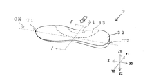
- FIG. 1 shows a shoe formed using the shoe sole member of the present embodiment.
- the shoe 1 includes an upper material 2 and shoe sole members 3 and 4.
- the shoe 1 includes a midsole 3 and an outer sole 4 as the sole member.
- FIG. 2 shows the midsole 3
- FIG. 3 is a cross-sectional view of the midsole 3.
- the member for soles of this invention is demonstrated taking this midsole 3 as an example.
- the direction along the shoe center axis CX connecting the tip end T1 of the toe and the terminal end T2 of the heel is referred to as the “length direction” of the shoe, and the direction indicated by the arrow X1 in the figure. Is referred to as “front”, and the direction indicated by the arrow X2 is referred to as “rear”.
- the direction parallel to the horizontal plane among the directions orthogonal to the shoe center axis CX is referred to as the “width direction” of the shoe, and the direction parallel to the vertical plane is the “height direction” or “thickness direction” of the shoe. ".
- the direction indicated by the arrow Y1 in the drawing is referred to as “inside”, and the direction indicated by the arrow Y2 is referred to as “outside”.
- the direction indicated by the arrow Z1 in the drawing is referred to as “upper side”, and the direction indicated by the arrow Z2 is referred to as “lower side”.
- the midsole 3 of the present embodiment is formed of at least two types of polymer compositions, and includes a first polymer composition (hereinafter also simply referred to as “first composition”) and a second polymer composition (hereinafter simply referred to as “first composition”). It is also formed by two types of polymer compositions (also referred to as “second composition”).
- the midsole 3 includes a first part 31 formed of the first composition and a second part 32 formed of the second composition.
- the midsole 3 includes the first part 31 and the second part 32.
- a third portion 33 formed by a mixture of the first composition and the second composition is provided therebetween.
- the first part 31 and the second part 32 are formed of different polymer compositions, so that different characteristics are exhibited therebetween.
- the first composition is harder than the second composition
- the first part 31 is harder than the second part 32.
- the first part 31 and the second part 32 have different Asker C hardnesses measured at 23 ° C. by a JIS K7312 type C spring hardness tester.
- the midsole 3 has a flat shape, and the outline in plan view has the same shape as the outline of the shoe 1.
- the first part 31 and the second part 32 are adjacent to each other via the third part 33 in the horizontal direction, and the first part 31 is located at a position corresponding to an inner foot part of a foot.
- the second portion 32 is disposed at a position corresponding to the outer foot portion of the foot. More specifically, the first part 31 is disposed at a position corresponding to the arch inside the middle foot part, and the second part 32 is disposed at a position corresponding to the front foot part, the rear foot part, and the middle foot part outside.
- the third part 33 is arranged between them. That is, the third part 33 is arranged along the outer edge of the arch.
- the midsole 3 of this embodiment has moderate cushioning properties.
- the Asker C hardness of the first part 31 is preferably 80 ° or less, and more preferably 75 ° or less.
- the Asker C hardness of the second portion 32 is preferably 65 ° or less, and more preferably 60 ° or less.
- the Asker C hardness of the first part 31 is preferably 50 ° or more, and more preferably 60 ° or more.
- the Asker C hardness of the second part 32 is preferably 35 ° or more, and more preferably 40 ° or more.
- the difference between the Asker C hardness of the first part 31 and the Asker C hardness of the second part 32 is preferably 4 ° or more and 20 ° or less, and more preferably 8 ° or more and 16 ° or less.
- the midsole 3 in which the first portion 31 that is harder than the second portion 32 is disposed on the arch prevents the user from losing balance when the user of the shoe 1 walks or runs. be able to. That is, the shoe 1 of the present embodiment can prevent the user's foot from falling inward during walking and running by arranging the relatively hard first portion 31 on the inner foot.
- the shoe 1 of the present embodiment has an uncomfortable feeling due to the difference in hardness between the first part 31 and the second part 32 because the third part 33 exists between the first part 31 and the second part 32. It is difficult for the user to feel it. Therefore, the user can feel comfort in walking and running by wearing the shoe 1 of the present embodiment.
- the midsole 3 is preferably formed so that the resilience elastic force in the thickness direction gradually increases from the inside toward the outside.
- the proportion of the third portion 33 in the midsole 3 is high.
- the existence ratio of the third part 33 is excessively increased, the existence ratio of the first part and the second part is lowered. In that case, there is a possibility that the first part and the second part cannot sufficiently function.
- the proportion of the third portion 33 in the midsole 3 is within a certain range in a cross section cut along a plane orthogonal to the shoe center axis CX.
- the cross-sectional area of the first portion 31 is S11 (cm 2 ) and the cross-sectional area of the second portion 32 is S12 in a cross section that is a plane orthogonal to the shoe center axis CX. (Cm 2 ), when the cross-sectional area of the third portion 33 is S13 (cm 2 ), the following relational expression (1) is preferably satisfied, more preferably the relational expression (2) is satisfied, and the relational expression (3 It is more preferable to satisfy
- the midsole 3 satisfy
- the midsole 3 preferably satisfies the relational expression (1) in all cross sections when the area of each part in the cross section is obtained in a section of 10 mm or more continuous in the length direction, and is preferably 20 mm or more. It is preferable that the relational expression (1) is satisfied in all the cross sections of the section.
- the section satisfying the relational expression (1) is usually 150 mm or less. About the cross-sectional area of each part in the mid sole 3, it can obtain
- the midsole 3 is cut along the surface whose hardness is to be measured.
- the midsole 3 is sliced along a plane parallel to the measurement surface, and a test piece having a thickness of about 5 mm is collected.
- the area (S11 + S12 + S13) of the surface which measures hardness is calculated
- the Asker C hardness is measured at a plurality of locations in a region as far as possible from the second part in the cross section of the first part, and the lowest value among the obtained data is determined as the standard hardness (H1) of the first part.
- the Asker C hardness at a plurality of locations is measured in a region as far as possible from the first part in the cross section of the second part, and the highest value among the obtained data is determined as the standard hardness (H2 of the second part).
- the Asker C hardness was measured for the entire cross section of the test piece, and the region showing a hardness equal to or higher than the standard hardness (H1) of the first part was recognized as the cross section of the first part.
- region which showed the hardness below the standard hardness (H2) of 2nd part this is recognized as a cross section of 2nd part, and each area (S11, S12) is calculated
- the sectional area (S13) of the third part can be calculated by subtracting the sectional area (S11) of the first part and the sectional area (S12) of the second part from the area of the test piece obtained first. .
- first composition and the second composition contain characteristic components, and the boundary between the first part and the third part and the boundary between the second part and the third part are determined by concentration analysis of the component. If possible, the cross-sectional area (S11, S12, S13) of each part may be obtained by component analysis.
- the hardness change of the 3rd part 33 from the 1st part side toward the 2nd part side is gentle. Therefore, it is preferable that the hardness of the third part in the cross section gradually decreases when the measurement point is moved from the first part side toward the second part side. That is, the midsole 3 of the present embodiment has a unit length in the moving direction when the measurement point is moved in the horizontal direction from the inside to the outside and the hardness of the third portion 33 in the cross section is measured. It is preferable that the amount of decrease in the hit hardness is 0.1 ° / mm or less over the entire area of the third portion 33.
- the hardness of the third portion 33 can be obtained by measuring Asker C hardness at intervals of 1 mm along a horizontal line passing through the central portion in the thickness direction of the third portion 33, for example. It is preferable that the third portion 33 exhibits the above-described decrease in hardness in the cross section passing through at least the central portion in the length direction of the arch.
- the midsole 3 preferably exhibits the above-described decrease in hardness in all cross sections when the hardness of the third portion 33 in the cross section is obtained in a section of 10 mm or more continuous in the length direction. It is preferable that the hardness decrease as described above is exhibited in all the cross sections in a section of 20 mm or more. In addition, the said area which shows the above hardness fall is 100 mm or less normally.
- the hardness of the third part in the cross section changes not only when the measurement point is moved in the horizontal direction but also when the measurement point is moved in the vertical direction. That is, the midsole 3 of the present embodiment moves the measurement point in the moving direction of the measurement point when the measurement point is moved upward from the central portion in the thickness direction and the hardness of the third portion 33 in the cross section is measured. It is preferable that the hardness gradually decreases toward the surface. In addition, the midsole 3 of the present embodiment moves in the moving direction of the measurement point when the measurement point is moved downward from the central portion in the thickness direction and the hardness of the third portion 33 in the cross section is measured. It is preferable that the hardness gradually decreases toward the surface.
- the midsole 3 is preferably formed of a polymer foam in that it is easy to add such a change in hardness and easily exhibit excellent cushioning properties.
- a preform which is smaller than the midsole 3 and is substantially non-foamed is temporarily manufactured, and the preform is formed into a molding die having a cavity corresponding to the shape of the midsole 3. It can be produced by a method in which a body is accommodated and the preform is heated and foamed in the cavity.
- the preform can be produced, for example, by injection molding, and a mold having a cavity corresponding to the preform, a nozzle for introducing the polymer composition into the cavity, and the polymer composition are melted. It can produce using the injection apparatus provided with the cylinder kneaded together and supplied to the said nozzle. More specifically, the preform includes, for example, a molding die in which a runner that guides a molten polymer composition supplied from the nozzle into a cavity opens at a position corresponding to an arch, and a first cylinder as the first mold.
- the following steps (a) to (c) can be carried out using an injection apparatus having at least two cylinders: a cylinder and a second cylinder.
- a part far from the part corresponding to the arch is formed with the second composition, and the part corresponding to the arch is formed with the first composition.
- the midsole as shown in FIG. 2 can be produced by foaming this preform as mentioned above.
- polyethylene for example, linear low density polyethylene (LLDPE), high density polyethylene (HDPE)
- LLDPE linear low density polyethylene
- HDPE high density polyethylene
- polypropylene ethylene-propylene copolymer
- propylene-1-hexene copolymer propylene-4-methyl-1-pentene copolymer
- propylene-1-butene copolymer ethylene-1-hexene copolymer
- ethylene -4-methyl-pentene copolymer ethylene-butene copolymer
- EBM 1-butene-1-hexene copolymer
- 1-butene-4-methyl-pentene ethylene-methacrylic acid copolymer
- ethylene -Methyl methacrylate copolymer ethylene-ethyl methacrylate copolymer
- ethylene-butyl methacrylate copolymer Ethylene-methyl
- the polymer may be a polyurethane polymer such as polyester polyurethane or polyether polyurethane; styrene-ethylene-butylene copolymer (SEB), styrene-butadiene-styrene copolymer.
- SEB styrene-ethylene-butylene copolymer
- SBS hydrogenated product of SBS (styrene-ethylene-butylene-styrene copolymer (SEBS)), styrene-isoprene-styrene copolymer (SIS), hydrogenated product of SIS (styrene-ethylene-propylene-styrene) Copolymer (SEPS)), styrene-isobutylene-styrene copolymer (SIBS), styrene-butadiene-styrene-butadiene (SBSB), styrene-butadiene-styrene-butadiene-styrene (SBSBS), polystyrene, acrylonitrile Styrene resin (AS resin), acrylonitrile butadiene styrene resin (ABS resin) can be employed one or more selected from styrene-based polymers such as styrene-based thermoplastic
- polymers that can be used as the polymer in the present embodiment include, for example, fluorine-based polymers such as fluororesin and fluororubber; polyamide-based materials such as polyamide 6, polyamide 11, polyamide 12, polyamide 6, 6, and polyamide 610.
- Polyamide polymers such as resins and polyamide elastomers; polyester resins such as polyethylene terephthalate and polybutylene terephthalate; polyvinyl chloride resins; acrylic resins such as polymethyl methacrylate; silicone elastomers; butadiene rubber (BR); isoprene rubber (IR); chloroprene (CR); natural rubber (NR); styrene butadiene rubber (SBR); acrylonitrile butadiene rubber (NBR); butyl rubber (IIR).
- BR butadiene rubber
- IR isoprene rubber
- CR chloroprene
- NR natural rubber
- SBR styrene butadiene rubber
- NBR acrylonitrile butadiene rubber
- IIR butyl rubber
- the polymer which is the main component of each of the first composition and the second composition has the same melt mass flow rate (MFR) for easy mixing of the first composition and the second composition. It is preferable to have.
- the polymer employed as the main component of each of the first composition and the second composition is a polymer with a high MFR of “M-FR” for MFR and “L-MFR” for a polymer with a low MFR.
- MFR melt mass flow rate
- H-MFR” / “L-MFR” are preferably 3 or less, more preferably 2 or less, still more preferably 1.5 or less, It is still more preferable that it is 1.2 or less, and it is especially preferable that it is 1.1 or less.
- the polymer preferably has an MFR of 5 g / 10 min or more, and more preferably an MFR of 10 g / 10 min or more.
- the polymer that is the main component of the first composition and the second composition is an ethylene-1-butene copolymer because it has an advantage that foam molding can be easily performed.
- ethylene- ⁇ / olefin copolymer such as a polymer (EBM), a styrene elastomer such as a styrene-ethylene / butylene-styrene copolymer (SEBS), or an ethylene-vinyl acetate copolymer (EVA).
- EBM polymer
- SEBS styrene-ethylene / butylene-styrene copolymer
- EVA ethylene-vinyl acetate copolymer
- MFR of ethylene-1-butene copolymer or ethylene-vinyl acetate copolymer can be determined under conditions of a temperature of 190 ° C. and a nominal load of 2.16 kg. Further, MFR such as styrene-ethylene / butylene-styrene copolymer can be determined under the conditions of a temperature of 230 ° C. and a nominal load of 2.16 kg.
- Such a polymer may be crosslinked and foamed, and the method of crosslinking and foaming is not particularly limited, and a crosslinking agent used for forming a general crosslinked foam and a foaming agent are also used in this embodiment.
- a crosslinking agent used for forming a general crosslinked foam and a foaming agent are also used in this embodiment.
- the crosslinking agent for example, organic peroxides, maleimide crosslinking agents, sulfur, phenolic crosslinking agents, oximes, polyamines and the like can be adopted, and among them, organic peroxides are preferable.
- organic peroxide examples include dicumyl peroxide, di-t-butyl peroxide, 2,5-dimethyl-2,5-di- (t-butylperoxy) hexane, 2,5-dimethyl-2,5.
- the organic peroxide is usually used at a ratio of 0.01 parts by mass or more and 10 parts by mass or less with respect to 100 parts by mass in total of the polymers contained in the first composition and the second composition.
- the first composition and the second composition may contain a crosslinking aid together with the crosslinking agent.
- the crosslinking aid include divinylbenzene, trimethylolpropane trimethacrylate, 1,6-hexanediol methacrylate, 1,9-nonanediol dimethacrylate, 1,10-decanediol dimethacrylate, trimellitic acid triallyl ester.
- inorganic particles having high surface energy such as clay, talc, silica, and carbon black are contained in the first composition and the second composition, and the inorganic particles are used in the first and second molding materials.
- a pseudo-crosslinking point may be formed.
- the method for foaming the polymer is not particularly limited, and foam molding can be performed by a chemical foaming method using an organic or inorganic chemical foaming agent or a physical foaming method using a physical foaming agent.
- foaming agent include azodicarbonamide (ADCA), 1,1′-azobis (1-acetoxy-1-phenylethane), dimethyl-2,2′-azobisbutyrate, dimethyl-2,2 ′.
- foaming agent examples include bicarbonates such as sodium bicarbonate and ammonium bicarbonate, carbonates such as sodium carbonate and ammonium carbonate; nitrites such as ammonium nitrite, and inorganic pyrolytic foaming agents such as hydrogen compounds.
- bicarbonates such as sodium bicarbonate and ammonium bicarbonate
- carbonates such as sodium carbonate and ammonium carbonate
- nitrites such as ammonium nitrite
- inorganic pyrolytic foaming agents such as hydrogen compounds.
- the 1 type (s) or 2 or more types selected can be employ
- organic foaming agents such as various aliphatic hydrocarbons such as methanol, ethanol, propane, butane, pentane and hexane, and inorganic foaming agents such as air, carbon dioxide, nitrogen, argon and water are also used as the crosslinked foam. It can be used as a foaming agent when forming.
- Examples of other additives to be contained in the first composition and the second composition include a dispersant, a processing aid, an antifungal agent, a flame retardant, a pigment, a release agent, an antistatic agent, an antibacterial agent, and a deodorant. Is mentioned.
- the first composition and the second composition have different colors.
- the midsole 3 can make a marble pattern and gradation appear by the said 3rd part by making a 1st composition and a 2nd composition differ in a color tone, and can aim at the improvement of aesthetics.
- the midsole in which the first part is arranged at a position corresponding to the arch is illustrated.
- the first part 31 is placed on the toe as shown in FIGS.
- the second portion 32 may be disposed at a position corresponding to the heel portion (rear foot portion).
- the cross-sectional area of the first portion 31 in the vertical cross section that is a vertical plane parallel to the shoe center axis CX is S21 (cm 2 ), and the cross-sectional area of the second portion is S22 (cm 2).
- the midsole 3 preferably satisfies the relational expression (4) in at least the longitudinal section passing through the shoe center axis CX.
- the midsole 3 preferably satisfies the relational expression (4) in all longitudinal sections when the area of each part in the longitudinal section is obtained in a section of 5 mm or more continuous in the width direction. It is preferable that the relational expression (4) is satisfied in all the longitudinal sections.
- the section that satisfies the relational expression (4) is usually 50 mm or less.
- the first portion 31 is harder than the second portion 32, and the measurement point is moved from the first portion side toward the second portion side.
- the hardness of the third part 33 it is preferable that the hardness of the third part decreases in the direction of movement.
- the amount of decrease per unit length in the direction is preferably 0.1 ° / mm or less over the entire area of the third part.
- the third portion 33 exhibits the above-described decrease in hardness in the longitudinal section passing through at least the shoe center shaft of the arch.
- the midsole 3 calculates the hardness of the third portion 33 in the longitudinal section in a section of 5 mm or more continuous in the width direction, it is preferable to show the above-described decrease in hardness in all longitudinal sections, It is preferable that the above-described decrease in hardness is exhibited in all the longitudinal sections in a section of 10 mm or more.
- the said area which shows the above hardness fall is 50 mm or less normally.
- the case where the first part and the second part are adjacent to each other via the third part in the horizontal direction is illustrated.
- the shoe sole member may be such that the first portion and the second portion are adjacent to each other via the third portion in the thickness direction. That is, the comfort of the shoe of the present invention is not greatly impaired by the arrangement of the first part and the second part.
- the midsole is illustrated as a member for soles provided with 1st part, 2nd part, and 3rd part
- the member for soles of this invention is other than midsole.
- it may be an outer sole.
- the member for shoes sole and shoes which concern on this invention are not limited to the said embodiment at all, A various change is possible in the range which does not deviate from the summary of this invention.
- a shoe sole member whose cross-sectional shape cut by a vertical surface is a horizontally long rectangle having a width of 20 mm and a height of 10 mm was used as a model, and the situation when pressure was applied to the shoe sole member was simulated by a finite element method.
- an insole region IS having a thickness of 1 mm was formed at the top.
- a 9 mm thick region (hereinafter also referred to as “lower region LP”) below the insole region IS is divided in the width direction. That is, in the model, one end in the width direction of the lower region LP is a soft region LS and the other end is a hard region LH, and an intermediate region LM is formed therebetween.
- the intermediate region LM corresponds to the portion indicated as the third portion 33 in FIGS.
- the simulation was performed by dividing the shoe sole member into a total of 5000 elements in the cross section, 100 pieces in the horizontal (width) direction and 50 pieces in the vertical (height) direction.
- Condition A the condition that the displacement of the base is constrained in translation and rotation in all directions
- Condition B the condition that the displacement of the base is constrained in translation and rotation in all directions at the leftmost node, and at other nodes It was performed under the condition (condition B) restrained in translation and rotation in the length direction and the height direction.
- FIGS. 7 and 8 show the simulation results.
- the horizontal axis represents the formation width of the intermediate region LM (the ratio of the intermediate region LM to the entire shoe sole member), and the vertical axis represents the first. This represents the shear stress generated at one boundary point L1 (a point corresponding to the boundary between the soft region and the intermediate region).
- the horizontal axis represents the formation width of the intermediate region LM (the ratio of the intermediate region LM to the entire shoe sole member), and the vertical axis corresponds to the second boundary point L2 (the boundary between the intermediate region and the hard region). This represents the shear stress generated at the point.
- the results shown by the diamond legend are those of the previous condition A, and the results shown by the square are those of the previous condition B.
- the fact that the shear stress generated at the first boundary point L1 and the second boundary point L2 indicates a high value means that a strong reaction force is applied when pressure is applied to the shoe sole member.
- a low value means that it is difficult for the user to feel a sense of incongruity due to the difference in hardness between the regions sandwiching the boundary. That is, a low value of the shear stress means that the user has excellent comfort.
- the shoe sole member was formed of two types of ethylene-vinyl acetate copolymers (EVA) having different hardnesses and two types of chlorinated polyethylenes (CPE) having different hardnesses.
- EVA ethylene-vinyl acetate copolymers
- CPE chlorinated polyethylenes
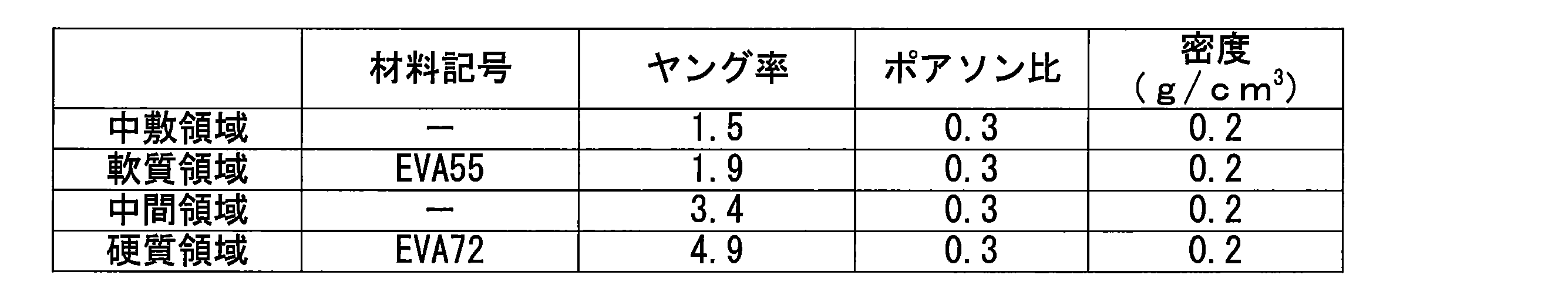
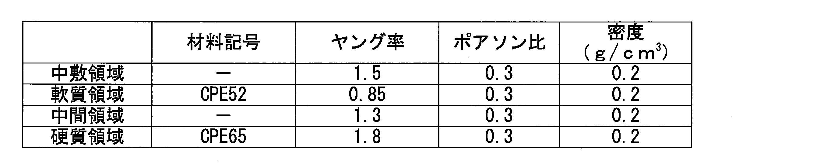
- the insole region IS, the soft region LS, the intermediate region LM, and the hard region LH are foams shown in Table 1 below was simulated.
- CPE the insole region IS, the soft region LS, the intermediate region LM, and the hard region LH were simulated in two ways shown in Tables 2 and 3 below.
- FIGS. 9 and 10 the results shown by the diamond legend are those of EVA in Table 1, the results shown by squares are the CPE of Table 2, and the results shown by triangles are those of the CPE of Table 3. It is.
- the horizontal axis represents the formation width of the intermediate region LM, and the vertical axis represents the shear stress generated at the first boundary point L1, as in FIG. 10, the horizontal axis represents the formation width of the intermediate region LM, and the vertical axis represents the shear stress generated at the second boundary point L2, as in FIG.
- the formation of the intermediate region LM can make the shoe sole member excellent in comfort, and the intermediate region LM can be formed by 5% or more.
- the fact that the shoe sole member can be made more comfortable is exhibited regardless of the material for forming the shoe sole member.
Abstract
第1ポリマー組成物と第2ポリマー組成物との少なくとも2種類のポリマー組成物によって形成され、前記第1ポリマー組成物によって形成された第1部と、前記第2ポリマー組成物によって形成された第2部とを備えており、前記第1部と前記第2部との間に、前記第1ポリマー組成物と前記第2ポリマー組成物との混合物によって形成された第3部を備えている靴底用部材を提供する。
Description
本発明は、靴底用部材、及び、靴に関し、より詳しくは、例えば、インナーソール、ソックライナー、ミッドソール、アウターソール等として用いられる靴底用部材、及び、このような靴底用部材を備えた靴に関する。
各種競技等に使用されるシューズは、多くの部材から構成されており、例えば、靴底であれば、インナーソール、ソックライナー、ミッドソール、アウターソール等の靴底用部材から構成されている。
従来、シューズに対して快適性を発揮させるために部分的に硬さが異なる靴底用部材を用いてシューズを形成することが行われている。
例えば、下記特許文献1には、“ファイロン・ビスケット”と称される複数の発泡性の部材を金型内に収容し、この複数の部材を金型内で加熱して発泡させるとともにこれらの部材どうしを一体化させて部分的に硬さの異なる靴底用部材を作製することが記載されている。
従来、シューズに対して快適性を発揮させるために部分的に硬さが異なる靴底用部材を用いてシューズを形成することが行われている。
例えば、下記特許文献1には、“ファイロン・ビスケット”と称される複数の発泡性の部材を金型内に収容し、この複数の部材を金型内で加熱して発泡させるとともにこれらの部材どうしを一体化させて部分的に硬さの異なる靴底用部材を作製することが記載されている。
特許文献1に記載の製法では、金型で一体化させる複数の部材のうちの一つを他の部材と異なるポリマー組成物によって作製しておけば、当該部材によって形成された部位が他の部位とは異なる特性を示す靴底用部材を得ることができる。
しかしながら、特許文献1に記載の製法で得られる靴底用部材は、硬さが異なる部材を隣り合わせにしたりすると部材の境界部でクッション性が急に変化することになる。
そして、このような靴底用部材を備えた靴は、使用者に違和感を与え、十分な快適性が発揮されないおそれがある。
しかしながら、特許文献1に記載の製法で得られる靴底用部材は、硬さが異なる部材を隣り合わせにしたりすると部材の境界部でクッション性が急に変化することになる。
そして、このような靴底用部材を備えた靴は、使用者に違和感を与え、十分な快適性が発揮されないおそれがある。
そこで、本発明は、快適性に優れた靴の形成に有効な靴底用部材を提供し、ひいては、快適性に優れた靴を提供することを課題とする。
上記課題を解決するための靴底用部材に係る本発明は、第1ポリマー組成物と第2ポリマー組成物との少なくとも2種類のポリマー組成物によって形成され、前記第1ポリマー組成物によって形成された第1部と、前記第2ポリマー組成物によって形成された第2部とを備えており、前記第1部と前記第2部との間に、前記第1ポリマー組成物と前記第2ポリマー組成物との混合物によって形成された第3部を備えている。
また、上記課題を解決するための靴に係る本発明は、上記のような靴底用部材を備えている。
本発明の靴底用部材について以下にその実施の形態を例示しつつ説明する。
本発明の靴底用部材は、少なくとも第1ポリマー組成物と第2ポリマー組成物との2種類のポリマー組成物によって形成され、前記第1ポリマー組成物によって形成された第1部と、前記第2ポリマー組成物によって形成された第2部とを備えており、前記第1部と前記第2部との間に、前記第1ポリマー組成物と前記第2ポリマー組成物との混合物によって形成された第3部を備えている。
靴底用部材は、前記第1部と前記第2部との間に備えられた前記第3部が第1ポリマー組成物と前記第2ポリマー組成物との混合物によって形成されているため、前記第1部と前記第2部との中間的な特性を当該第3部に発揮させることができる。
従って、靴底用部材は、前記第1部と前記第2部との間で特性が大きく変化することが抑制され、靴を快適性に優れたものとすることができる。
靴をより快適性に優れたものとする上において、本実施形態の靴底用部材は、扁平形状を有し、水平方向において前記第1部と前記第2部とが前記第3部を介して隣接していることが好ましい。
また、本実施形態の靴底用部材は、靴をより快適性に優れたものとする上において、シューセンター軸に直交する横断面での第1部の断面積をS11、第2部の断面積をS12、第3部の断面積をS13とした際に下記関係式(1)を満たすことが好ましい。
5%≦〔100×S13/(S11+S12+S13)〕<100% ・・・(1)
また、本実施形態の靴底用部材は、靴をより快適性に優れたものとする上において、シューセンター軸に直交する横断面での第1部の断面積をS11、第2部の断面積をS12、第3部の断面積をS13とした際に下記関係式(1)を満たすことが好ましい。
5%≦〔100×S13/(S11+S12+S13)〕<100% ・・・(1)
本実施形態の靴底用部材は、第1部が第2部に比べて硬く、第1部側から第2部側に向けて測定点を移動させて前記横断面における前記第3部のアスカーC硬度を測定した際に、該アスカーC硬度の値が前記移動の方向に向けて低下することが好ましい。
このような好ましい態様によれば、靴底用部材の厚み方向に圧力を加えた際に局所的に強い反力を生じることがより確実に抑制され得る。
このような好ましい態様によれば、靴底用部材の厚み方向に圧力を加えた際に局所的に強い反力を生じることがより確実に抑制され得る。
本実施形態の靴底用部材は、前記横断面における前記第3部のアスカーC硬度の値が、測定点を水平方向に移動させた場合、及び、垂直方向に移動させた場合の両方において変化することが好ましい。
このような好ましい態様によれば、靴底用部材に水平方向のみならず垂直方向においてもクッション性の変化を持たせることができ、3次元的な特性変化を靴底用部材に発揮させ得る。
このような好ましい態様によれば、靴底用部材に水平方向のみならず垂直方向においてもクッション性の変化を持たせることができ、3次元的な特性変化を靴底用部材に発揮させ得る。
本実施形態の靴底用部材は、前記第1部が内足部に配され、前記第2部が前記第1部よりも外足部に配されていることが好ましい。
このような好ましい態様の靴底用部材を備えさせることで靴をより快適なものとすることができる。
このような好ましい態様の靴底用部材を備えさせることで靴をより快適なものとすることができる。
本実施形態の靴底用部材は、シューセンター軸に平行する垂直面である縦断面における第1部の断面積をS21、第2部の断面積をS22、第3部の断面積をS23とした際に下記関係式(4)を満たすことが好ましい。
5%≦〔100×S23/(S21+S22+S23)〕<100% ・・・(4)
また、本実施形態の靴底用部材は、第1部が第2部に比べて硬く、第1部側から第2部側に向けて測定点を移動させて前記縦断面における前記第3部のアスカーC硬度を測定した際に、該アスカーC硬度の値が前記移動の方向に向けて低下することが好ましい。
このような好ましい態様の靴底用部材を備えさせることで靴をより快適なものとすることができる。
5%≦〔100×S23/(S21+S22+S23)〕<100% ・・・(4)
また、本実施形態の靴底用部材は、第1部が第2部に比べて硬く、第1部側から第2部側に向けて測定点を移動させて前記縦断面における前記第3部のアスカーC硬度を測定した際に、該アスカーC硬度の値が前記移動の方向に向けて低下することが好ましい。
このような好ましい態様の靴底用部材を備えさせることで靴をより快適なものとすることができる。
即ち、本実施形態の靴は、上記のような靴底用部材を備えることで、使用者に快適性を与えうる。
なお、図1は、本実施形態の靴底用部材を用いて形成される靴を示したものである。
該靴1は、アッパー材2と靴底用部材3,4とを有している。
該靴1は、前記靴底用部材として、ミッドソール3、及び、アウターソール4を有している。
図2は、前記ミッドソール3を示したもので、図3は、該ミッドソール3の断面図である。
なお、図1は、本実施形態の靴底用部材を用いて形成される靴を示したものである。
該靴1は、アッパー材2と靴底用部材3,4とを有している。
該靴1は、前記靴底用部材として、ミッドソール3、及び、アウターソール4を有している。
図2は、前記ミッドソール3を示したもので、図3は、該ミッドソール3の断面図である。
以下においては、該ミッドソール3を例にして本発明の靴底用部材について説明する。
なお、以下においては、爪先の最先端T1と踵の最末端T2とを結ぶシューセンター軸CXに沿った方向を靴の“長さ方向”と称し、図中に矢印X1で示されている方向を“前方”、矢印X2で示されている方向を“後方”と称する。
また、以下においては前記シューセンター軸CXに直交する方向の内、水平面と平行する方向を靴の“幅方向”と称し、垂直面と平行する方向を靴の“高さ方向”又は“厚み方向”と称する。
そして、以下においては、“幅方向”の内、図中に矢印Y1で示されている方向を“内側”、矢印Y2で示されている方向を“外側”と称する。
また、以下においては、“高さ方向”又は“厚み方向”の内、図中に矢印Z1で示されている方向を“上側”、矢印Z2で示されている方向を“下側”と称する。
本実施形態のミッドソール3は、少なくとも2種類のポリマー組成物によって形成されており、第1ポリマー組成物(以下、単に「第1組成物」ともいう)と第2ポリマー組成物(以下、単に「第2組成物」ともいう)との2種類のポリマー組成物によって形成されている。
ミッドソール3は、前記第1組成物によって形成された第1部31と、前記第2組成物によって形成された第2部32とを備え、前記第1部31と前記第2部32との間に、前記第1組成物と前記第2組成物との混合物によって形成された第3部33を備えている。
ミッドソール3は、前記第1組成物によって形成された第1部31と、前記第2組成物によって形成された第2部32とを備え、前記第1部31と前記第2部32との間に、前記第1組成物と前記第2組成物との混合物によって形成された第3部33を備えている。
本実施形態のミッドソール3は、第1部31と第2部32とが異なるポリマー組成物によって形成されることでこれらの間に異なる特性を発揮させている。
該ミッドソール3は、前記第2組成物に比べて前記第1組成物の方が硬質で、第2部32に比べて第1部31の方が硬くなっている。
具体的には、第1部31と第2部32とは、JIS K7312のタイプCスプリング硬さ試験機によって23℃において測定されるアスカーC硬度を異ならせている。
該ミッドソール3は、前記第2組成物に比べて前記第1組成物の方が硬質で、第2部32に比べて第1部31の方が硬くなっている。
具体的には、第1部31と第2部32とは、JIS K7312のタイプCスプリング硬さ試験機によって23℃において測定されるアスカーC硬度を異ならせている。
前記ミッドソール3は、扁平形状を有し、平面視における輪郭が靴1の輪郭と同様の形状を有している。
前記ミッドソール3は、水平方向において前記第1部31と前記第2部32とが前記第3部33を介して隣接しており、足の内足部に対応する位置に前記第1部31が配され、足の外足部に対応する位置に前記第2部32が配されている。
より詳しくは、中足部内側の土踏まずに対応する位置に前記第1部31が配され、前足部、後足部、及び、中足部外側に対応する位置に前記第2部32が配されており、これらの間に前記第3部33が配されている。
即ち、前記第3部33は、土踏まずの外縁に沿うように配されている。
前記ミッドソール3は、水平方向において前記第1部31と前記第2部32とが前記第3部33を介して隣接しており、足の内足部に対応する位置に前記第1部31が配され、足の外足部に対応する位置に前記第2部32が配されている。
より詳しくは、中足部内側の土踏まずに対応する位置に前記第1部31が配され、前足部、後足部、及び、中足部外側に対応する位置に前記第2部32が配されており、これらの間に前記第3部33が配されている。
即ち、前記第3部33は、土踏まずの外縁に沿うように配されている。
本実施形態のミッドソール3は、適度なクッション性を有することが好ましい。
このようなことから、第1部31のアスカーC硬度は80°以下であることが好ましく、75°以下であることがより好ましい。
また、第2部32のアスカーC硬度は65°以下であることが好ましく、60°以下であることがより好ましい。
ただし、ミッドソール3は、過度に低硬度であると、当該靴底用部材を備えた靴1の履き心地を十分良好なものにすることが難しくなる。
従って、第1部31のアスカーC硬度は、50°以上であることが好ましく、60°以上であることがより好ましい。
また、第2部32のアスカーC硬度は、35°以上であることが好ましく、40°以上であることがより好ましい。
このようなことから、第1部31のアスカーC硬度は80°以下であることが好ましく、75°以下であることがより好ましい。
また、第2部32のアスカーC硬度は65°以下であることが好ましく、60°以下であることがより好ましい。
ただし、ミッドソール3は、過度に低硬度であると、当該靴底用部材を備えた靴1の履き心地を十分良好なものにすることが難しくなる。
従って、第1部31のアスカーC硬度は、50°以上であることが好ましく、60°以上であることがより好ましい。
また、第2部32のアスカーC硬度は、35°以上であることが好ましく、40°以上であることがより好ましい。
第1部31のアスカーC硬度と第2部32のアスカーC硬度との差は、4°以上20°以下であることが好ましく8°以上16°以下であることがより好ましい。
このように第2部32に比べて硬い第1部31が土踏まずに配されたミッドソール3は、靴1の使用者が歩行したり走ったりする際に使用者がバランスを崩すことを防止することができる。
即ち、本実施形態の靴1は、相対的に硬い第1部31が内足部に配置されることによって歩行時及び走行時において使用者の足が内向きに倒れることを防ぐことができる。
また、本実施形態の靴1は、第3部33が第1部31と第2部32との間に存在することで、第1部31と第2部32との硬さの違いによる違和感を使用者に感じさせ難い。
したがって、使用者は、本実施形態の靴1を着用することで歩行や走行において快適さを感じることができる。
即ち、本実施形態の靴1は、相対的に硬い第1部31が内足部に配置されることによって歩行時及び走行時において使用者の足が内向きに倒れることを防ぐことができる。
また、本実施形態の靴1は、第3部33が第1部31と第2部32との間に存在することで、第1部31と第2部32との硬さの違いによる違和感を使用者に感じさせ難い。
したがって、使用者は、本実施形態の靴1を着用することで歩行や走行において快適さを感じることができる。
また、ミッドソール3は、厚み方向における反発弾性力が内側から外側に向けて徐々に増加するように形成されていることが好ましい。
そのためには、ミッドソール3における第3部33の存在割合が高い方が好ましい。
一方で、第3部33の存在割合を過度に高くすると第1部や第2部は、その存在割合が低くなる。
その場合、第1部や第2部は、機能が十分に発揮できなくなる可能性がある。
そのようなことから、ミッドソール3は、シューセンター軸CXに直交する平面で切断した断面において第3部33の占める割合が一定の範囲内に収まっていることが好ましい。
具体的には、本実施形態のミッドソール3は、シューセンター軸CXに直交する平面たる横断面での第1部31の断面積をS11(cm2)、第2部32の断面積をS12(cm2)、第3部33の断面積をS13(cm2)とした際に下記関係式(1)を満たすことが好ましく、関係式(2)を満たすことがより好ましく、関係式(3)を満たすことが更に好ましい。
5%≦〔100×S13/(S11+S12+S13)〕<100% ・・・(1)
5%≦〔100×S13/(S11+S12+S13)〕≦80% ・・・(2)
15%≦〔100×S13/(S11+S12+S13)〕≦80% ・・・(3)
また、ミッドソール3は、少なくとも土踏まずの長さ方向中央部を通る前記横断面において関係式(1)を満たしていることが好ましい。
ミッドソール3は、長さ方向に連続する10mm以上の区間で前記横断面における各部の面積を求めた際に、全ての横断面において関係式(1)を満たしていることが好ましく、20mm以上の区間の全ての前記横断面において関係式(1)を満たしていることが好ましい。
なお、関係式(1)を満たしている前記区間は、通常、150mm以下である。
ミッドソール3における各部の断面積については、以下のようにして求めることができる。
ミッドソール3は、長さ方向に連続する10mm以上の区間で前記横断面における各部の面積を求めた際に、全ての横断面において関係式(1)を満たしていることが好ましく、20mm以上の区間の全ての前記横断面において関係式(1)を満たしていることが好ましい。
なお、関係式(1)を満たしている前記区間は、通常、150mm以下である。
ミッドソール3における各部の断面積については、以下のようにして求めることができる。
(各部の断面積の求め方)
まず、硬さを測定する面に沿ってミッドソール3を切断する。
次いで、この測定面と平行な面に沿ってミッドソール3をスライスし、厚み5mm程度の試験片を採取する。
そして、硬さを測定する面の面積(S11+S12+S13)を求める。
なお、この面積は、投影機などによって求めることができる。
次いで、第1部の断面の内、出来るだけ第2部から離れた領域において複数箇所のアスカーC硬度を測定し、得られたデータの内の最低値を第1部の標準硬さ(H1)とする。
同様に、第2部の断面の内、出来るだけ第1部から離れた領域において複数箇所のアスカーC硬度を測定し、得られたデータの内の最高値を第2部の標準硬さ(H2)とする。
最後に、試験片の断面全体に対してアスカーC硬度を測定し、第1部の標準硬さ(H1)以上の硬さを示した領域については、これを第1部の断面であると認定し、第2部の標準硬さ(H2)以下の硬さを示した領域については、これを第2部の断面であると認定してそれぞれ面積(S11、S12)を求める。
そして、最初に求めた試験片の面積から第1部の断面積(S11)と第2部の断面積(S12)とを差し引くことで第3部の断面積(S13)を算出することができる。
なお、第1組成物や第2組成物が特徴的な成分を含み、該成分の濃度分析などによって第1部と第3部との境界や、第2部と第3部との境界が判別可能である場合は、各部の断面積(S11、S12、S13)を成分分析によって求めるようにしてもよい。
また、第1部側から第2部側に向けての第3部33の硬さ変化は緩やかであることが好ましい。
従って、前記横断面における第3部の硬さは、第1部側から第2部側に向けて測定点を移動させて測定した際に緩やかに低下することが好ましい。
即ち、本実施形態のミッドソール3は、内側から外側に向けて水平方向に測定点を移動させて前記横断面における第3部33の硬さ測定を行った場合に、移動方向における単位長さ当たりの硬さの低下量が第3部33の全域に亘って0.1°/mm以下となることが好ましい。
従って、前記横断面における第3部の硬さは、第1部側から第2部側に向けて測定点を移動させて測定した際に緩やかに低下することが好ましい。
即ち、本実施形態のミッドソール3は、内側から外側に向けて水平方向に測定点を移動させて前記横断面における第3部33の硬さ測定を行った場合に、移動方向における単位長さ当たりの硬さの低下量が第3部33の全域に亘って0.1°/mm以下となることが好ましい。
該第3部33の硬さは、例えば、第3部33の厚み方向中央部を通る水平線に沿って1mm間隔でアスカーC硬度を測定することによって求めることができる。
第3部33は、少なくとも土踏まずの長さ方向中央部を通る前記横断面において上記のような硬さ低下を示すことが好ましい。
ミッドソール3は、長さ方向に連続する10mm以上の区間で前記横断面における第3部33の硬さを求めた際に、全ての横断面において上記のような硬さ低下を示すことが好ましく、20mm以上の区間の全ての前記横断面において上記のような硬さ低下を示すことが好ましい。
なお、上記のような硬さ低下を示す前記区間は、通常、100mm以下である。
第3部33は、少なくとも土踏まずの長さ方向中央部を通る前記横断面において上記のような硬さ低下を示すことが好ましい。
ミッドソール3は、長さ方向に連続する10mm以上の区間で前記横断面における第3部33の硬さを求めた際に、全ての横断面において上記のような硬さ低下を示すことが好ましく、20mm以上の区間の全ての前記横断面において上記のような硬さ低下を示すことが好ましい。
なお、上記のような硬さ低下を示す前記区間は、通常、100mm以下である。
前記横断面における前記第3部の硬さは、測定点を水平方向に移動させた場合のみならず測定点を垂直方向に移動させた場合においても変化することが好ましい。
即ち、本実施形態のミッドソール3は、厚み方向中央部から上方に向けて測定点を移動させて前記横断面における第3部33の硬さ測定を行った場合に、測定点の移動方向に向けて徐々に硬さが低下することが好ましい。
また、本実施形態のミッドソール3は、厚み方向中央部から下方に向けて測定点を移動させて前記横断面における第3部33の硬さ測定を行った場合に、測定点の移動方向に向けて徐々に硬さが低下することが好ましい。
即ち、本実施形態のミッドソール3は、厚み方向中央部から上方に向けて測定点を移動させて前記横断面における第3部33の硬さ測定を行った場合に、測定点の移動方向に向けて徐々に硬さが低下することが好ましい。
また、本実施形態のミッドソール3は、厚み方向中央部から下方に向けて測定点を移動させて前記横断面における第3部33の硬さ測定を行った場合に、測定点の移動方向に向けて徐々に硬さが低下することが好ましい。
このような硬さの変化を加えるのが容易であるとともに優れたクッション性を発揮させることが容易である点においてミッドソール3は、ポリマーフォームによって形成させることが好ましい。
ポリマーフォームからなるミッドソール3は、例えば、ミッドソール3よりも小さく実質的に非発泡な状態の予備成形体を一旦作製し、ミッドソール3の形状に対応したキャビティを有する成形型に前記予備成形体を収容して、前記キャビティ内で前記予備成形体を加熱して発泡させるような方法で作製することができる。
前記予備成形体は、例えば、射出成形によって作製することができ、予備成形体に対応したキャビティを有する成形型と、該キャビティ内にポリマー組成物を導入するためのノズル及びポリマー組成物を溶融させるとともに混練して前記ノズルに供給するシリンダーを備えた射出装置とを用いて作製することができる。
より詳しくは、前記予備成形体は、例えば、前記ノズルから供給される溶融状態のポリマー組成物をキャビティ内に案内するランナーが土踏まずに対応する位置に開口した成形型、及び、前記シリンダーとして第1のシリンダーと第2のシリンダーとの少なくとも2つのシリンダーを有する射出装置を用いて下記(a)~(c)のステップを実施して作製することができる。
(a)前記射出装置において発泡剤を含んだ第1組成物及び発泡剤を含んだ第2組成物をそれぞれ加熱して溶融状態にさせるステップ。
(b)キャビティの容積よりも少ない量の第2組成物を第1シリンダーから供給し、該第2組成物をノズルを通じて成形型に供給して、成形型内に余剰空間が生じる状態で第2組成物の供給を停止するステップ。
(c)第2組成物の供給停止後、第2のシリンダーから前記ノズルを通じて第1組成物を成形型に供給し、成形型内の残りの空間を第1組成物で充満させるステップ。
この(a)~(c)のステップを実施することにより、土踏まずに対応する部位から遠く離れた部位が第2組成物で形成され、土踏まずに対応する部位が第1組成物で形成されているとともにこれらの境界部が第1組成物と第2組成物との混合物で形成された予備成形体を作製することができる。
そして、この予備成形体を前記のように発泡させることで図2に示したようなミッドソールを作製することができる。
そして、この予備成形体を前記のように発泡させることで図2に示したようなミッドソールを作製することができる。
なお、第1組成物や第2組成物などのミッドソールの原材料については、一般的なものを採用することができる。
第1組成物や第2組成物の主成分となるポリマーとしては、オレフィン系のものであれば、例えば、ポリエチレン(例えば、直鎖状低密度ポリエチレン(LLDPE)、高密度ポリエチレン(HDPE))、ポリプロピレン、エチレン-プロピレン共重合体、プロピレン-1-ヘキセン共重合体、プロピレン-4-メチル-1-ペンテン共重合体、プロピレン-1-ブテン共重合体、エチレン-1-ヘキセン共重合体、エチレン-4-メチル-ペンテン共重合体、エチレン-ブテン共重合体(EBM)、1-ブテン-1-ヘキセン共重合体、1-ブテン-4-メチル-ペンテン、エチレン-メタクリル酸共重合体、エチレン-メタクリル酸メチル共重合体、エチレン-メタクリル酸エチル共重合体、エチレン-メタクリル酸ブチル共重合体、エチレン-メチルアクリレート共重合体、エチレン-エチルアクリレート共重合体、エチレン-ブチルアクリレート共重合体、プロピレン-メタクリル酸共重合体、プロピレン-メタクリル酸メチル共重合体、プロピレン-メタクリル酸エチル共重合体、プロピレン-メタクリル酸ブチル共重合体、エチレン-酢酸ビニル共重合体(EVA)、プロピレン-酢酸ビニル共重合体等から選択される1種又は2種以上を採用することができる。
また、オレフィン系以外のものであれば、前記ポリマーとしては、ポリエステル系ポリウレタン、ポリエーテル系ポリウレタン等のポリウレタン系ポリマー;スチレン-エチレン-ブチレン共重合体(SEB)、スチレン-ブタジエン-スチレン共重合体(SBS)、SBSの水素添加物(スチレン-エチレン-ブチレン-スチレン共重合体(SEBS))、スチレン-イソプレン-スチレン共重合体(SIS)、SISの水素添加物(スチレン-エチレン-プロピレン-スチレン共重合体(SEPS))、スチレン-イソブチレン-スチレン共重合体(SIBS)、スチレン-ブタジエン-スチレン-ブタジエン(SBSB)、スチレン-ブタジエン-スチレン-ブタジエン-スチレン(SBSBS)、ポリスチレン、アクリロニトリルスチレン樹脂(AS樹脂)、アクリロニトリルブタジエンスチレン樹脂(ABS樹脂)、スチレン系熱可塑性エラストマー(TPS)等のスチレン系ポリマー等から選択される1種又は2種以上を採用することができる。
さらに、本実施形態において前記ポリマーとして採用可能なポリマーを挙げると、例えば、フッ素樹脂やフッ素ゴムなどのフッ素系ポリマー;ポリアミド6、ポリアミド11、ポリアミド12、ポリアミド6,6、ポリアミド610などのポリアミド系樹脂やポリアミド系エラストマーといったポリアミド系ポリマー;ポリエチレンテレフタレート、ポリブチレンテレフタレートなどのポリエステル系樹脂;ポリ塩化ビニル系樹脂;ポリメタクリル酸メチルなどのアクリル系樹脂;シリコーン系エラストマー;ブタジエンゴム(BR);イソプレンゴム(IR);クロロプレン(CR);天然ゴム(NR);スチレンブタジエンゴム(SBR);アクリロニトリルブタジエンゴム(NBR);ブチルゴム(IIR)などが挙げられる。
なお、第1組成物及び第2組成物のそれぞれの主成分となるポリマーは、第1組成物及び第2組成物を混合容易なものとする上においてメルトマスフローレイト(MFR)が同等の値を有することが好ましい。
具体的には、第1組成物及び第2組成物のそれぞれの主成分として採用するポリマーは、MFRが高いポリマーのMFRを「H-MFR」、MFRが低いポリマーのMFRを「L-MFR」とした場合、これらの比率(「H-MFR」/「L-MFR」)が、3以下であることが好ましく、2以下であることがより好ましく、1.5以下であることが更に好ましく、1.2以下であることがより更に好ましく、1.1以下であることが特に好ましい。
また、本実施形態においては、上記例示のポリマーの中でも、射出成形を行いやすいという利点を有することからMFRの高い材料を第1組成物及び第2組成物の主成分とすることが好ましい。
具体的には、前記ポリマーは、MFRが5g/10min以上であることが好ましく、MFRが10g/10min以上であることがより好ましい。
また、本実施形態においては、上記例示のポリマーの中でも、発泡成形を容易に行えるという利点を有することから第1組成物と第2組成物の主成分となるポリマーは、エチレン-1-ブテン共重合体(EBM)などのエチレン-α・オレフィン共重合体、スチレン-エチレン/ブチレン-スチレン共重合体(SEBS)などのスチレン系エラストマー、エチレン-酢酸ビニル共重合体(EVA)などであることが好ましい。
なお、エチレン-1-ブテン共重合体やエチレン-酢酸ビニル共重合体などのMFRは、温度190℃、公称荷重2.16kgの条件下で求めることができる。
また、スチレン-エチレン/ブチレン-スチレン共重合体などMFRは、温度230℃、公称荷重2.16kgの条件下で求めることができる。
このようなポリマーは架橋発泡してもよく、架橋発泡させる手法は特に限定されず、一般的な架橋発泡体の形成に利用されている架橋剤、及び、発泡剤を本実施形態においても用いることができる。
該架橋剤としては、例えば、有機過酸化物、マレイミド系架橋剤、硫黄、フェノール系架橋剤、オキシム類、ポリアミン等を採用することが可能であるが、なかでも有機過酸化物が好ましい。
また、ポリマーの架橋には、電子線等の活性エネルギー線を用いることもできる。
該架橋剤としては、例えば、有機過酸化物、マレイミド系架橋剤、硫黄、フェノール系架橋剤、オキシム類、ポリアミン等を採用することが可能であるが、なかでも有機過酸化物が好ましい。
また、ポリマーの架橋には、電子線等の活性エネルギー線を用いることもできる。
前記有機過酸化物としては、例えば、ジクミルペルオキシド、ジ-t-ブチルペルオキシド、2,5-ジメチル-2,5-ジ-(t-ブチルペルオキシ)ヘキサン、2,5-ジメチル-2,5-ジ-(t-ブチルペルオキシ)ヘキシン-3、1,3-ビス(t-ブチルペルオキシイソプロピル)ベンゼン、1,1-ビス(t-ブチルペルオキシ)-3,3,5-トリメチルシクロヘキサン、n-ブチル-4,4-ビス(t-ブチルペルオキシ)バレレート、ベンゾイルペルオキシド、p-クロロベンゾイルペルオキシド、2,4-ジクロロベンゾイルペルオキシド、t-ブチルペルオキシベンゾエート、t-ブチルペルベンゾエート、t-ブチルペルオキシイソプロピルカーボネート、ジアセチルペルオキシド、ラウロイルペルオキシド、t-ブチルクミルペルオキシド等から選択される1種又は2種以上を採用することができる。
前記有機過酸化物は、通常、第1組成物、第2組成物に含有されるポリマーの合計100質量部に対して0.01質量部以上10質量部以下となる割合で使用される。
また、前記第1組成物、第2組成物には、前記架橋剤とともに架橋助剤を含有させることもできる。
この架橋助剤としては、例えば、ジビニルベンゼン、トリメチロールプロパントリメタクリレート、1,6-ヘキサンジオールメタクリレート、1,9-ノナンジオールジメタクリレート、1,10-デカンジオールジメタクリレート、トリメリット酸トリアリルエステル、トリアリルイソシアネート、ネオペンチルグリコールジメタクリレート、1,2,4-ベンゼントリカルボン酸トリアリルエステル、トリシクロデカンジメタクリレート、ポリエチレングリコールジアクリレート等から選択される1種又は2種以上を採用することができる。
この架橋助剤としては、例えば、ジビニルベンゼン、トリメチロールプロパントリメタクリレート、1,6-ヘキサンジオールメタクリレート、1,9-ノナンジオールジメタクリレート、1,10-デカンジオールジメタクリレート、トリメリット酸トリアリルエステル、トリアリルイソシアネート、ネオペンチルグリコールジメタクリレート、1,2,4-ベンゼントリカルボン酸トリアリルエステル、トリシクロデカンジメタクリレート、ポリエチレングリコールジアクリレート等から選択される1種又は2種以上を採用することができる。
また、本実施形態においては、クレー、タルク、シリカ、カーボンブラックといった表面エネルギーの高い無機物粒子を第1組成物及び第2組成物に含有させ、当該無機物粒子によって第1、2の成形材料中に擬似架橋点を形成させるようにしてもよい。
ポリマーを発泡させる手法は特に限定されず、有機系や無機系の化学発泡剤を用いた化学発泡法や、物理発泡剤を用いた物理発泡法により、発泡成形することができる。
前記発泡剤としては、例えば、アゾジカルボンアミド(ADCA)、1,1’-アゾビス(1-アセトキシ-1-フェニルエタン)、ジメチル-2,2’-アゾビスブチレート、ジメチル-2,2’-アゾビスイソブチレート、2,2’-アゾビス(2,4,4-トリメチルペンタン)、1,1’-アゾビス(シクロヘキサン-1-カルボニトリル)、2,2’-アゾビス[N-(2-カルボキシエチル)-2-メチル-プロピオンアミジン]等のアゾ化合物;N,N’-ジニトロソペンタメチレンテトラミン(DPT)等のニトロソ化合物;4,4’-オキシビス(ベンゼンスルホニルヒドラジド)、ジフェニルスルホン-3,3’-ジスルホニルヒドラジド等のヒドラジン誘導体;p-トルエンスルホニルセミカルバジド等のセミカルバジド化合物;トリヒドラジノトリアジンなどの有機系熱分解型発泡剤から選択される1種又は2種以上を採用することができる。
前記発泡剤としては、例えば、アゾジカルボンアミド(ADCA)、1,1’-アゾビス(1-アセトキシ-1-フェニルエタン)、ジメチル-2,2’-アゾビスブチレート、ジメチル-2,2’-アゾビスイソブチレート、2,2’-アゾビス(2,4,4-トリメチルペンタン)、1,1’-アゾビス(シクロヘキサン-1-カルボニトリル)、2,2’-アゾビス[N-(2-カルボキシエチル)-2-メチル-プロピオンアミジン]等のアゾ化合物;N,N’-ジニトロソペンタメチレンテトラミン(DPT)等のニトロソ化合物;4,4’-オキシビス(ベンゼンスルホニルヒドラジド)、ジフェニルスルホン-3,3’-ジスルホニルヒドラジド等のヒドラジン誘導体;p-トルエンスルホニルセミカルバジド等のセミカルバジド化合物;トリヒドラジノトリアジンなどの有機系熱分解型発泡剤から選択される1種又は2種以上を採用することができる。
また、前記発泡剤としては、炭酸水素ナトリウム、炭酸水素アンモニウム等の重炭酸塩、炭酸ナトリウム、炭酸アンモニウム等の炭酸塩;亜硝酸アンモニウム等の亜硝酸塩、水素化合物などの無機系熱分解型発泡剤から選択される1種又は2種以上を採用することができる。
さらに、メタノール、エタノール、プロパン、ブタン、ペンタン、ヘキサン等の各種脂肪族炭化水素類などの有機系発泡剤、空気、二酸化炭素、窒素、アルゴン、水などの無機系発泡剤も前記架橋発泡体を形成させる際の発泡剤として用いることができる。
前記第1組成物、第2組成物に含有させるその他の添加剤としては、分散剤、加工助剤、耐侯剤、難燃剤、顔料、離型剤、帯電防止剤、抗菌剤、消臭剤等が挙げられる。
なお、本実施形態のミッドソール3は、第1組成物と第2組成物とが色調を異ならせることが好ましい。
ミッドソール3は、第1組成物と第2組成物とが色調を異ならせることで前記第3部によってマーブル模様やグラデーションを現出させることができ、審美性の向上を図り得る。
ミッドソール3は、第1組成物と第2組成物とが色調を異ならせることで前記第3部によってマーブル模様やグラデーションを現出させることができ、審美性の向上を図り得る。
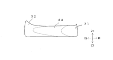
本実施形態においては、第1部を土踏まずに対応した位置に配したミッドソールを例示しているが、本発明においては、例えば、図4、図5に示したように第1部31を爪先部(前足部)に対応する位置に配し、第2部32を踵部(後足部)に対応する位置に配するようにしてもよい。
なお、この場合の靴底用部材は、シューセンター軸CXに平行する垂直面である縦断面における第1部31の断面積をS21(cm2)、第2部の断面積をS22(cm2)、第3部の断面積をS23(cm2)とした際に、下記関係式(4)を満たすことが好ましく、
下記関係式(5)を満たすことがより好ましく、下記関係式(6)を満たすことが更に好ましい。
5%≦〔100×S23/(S21+S22+S23)〕<100% ・・・(4)
5%≦〔100×S23/(S21+S22+S23)〕≦80% ・・・(5)
15%≦〔100×S23/(S21+S22+S23)〕≦80% ・・・(6)
なお、この場合の靴底用部材は、シューセンター軸CXに平行する垂直面である縦断面における第1部31の断面積をS21(cm2)、第2部の断面積をS22(cm2)、第3部の断面積をS23(cm2)とした際に、下記関係式(4)を満たすことが好ましく、
下記関係式(5)を満たすことがより好ましく、下記関係式(6)を満たすことが更に好ましい。
5%≦〔100×S23/(S21+S22+S23)〕<100% ・・・(4)
5%≦〔100×S23/(S21+S22+S23)〕≦80% ・・・(5)
15%≦〔100×S23/(S21+S22+S23)〕≦80% ・・・(6)
ミッドソール3は、少なくともシューセンター軸CXを通る前記縦断面において関係式(4)を満たしていることが好ましい。
ミッドソール3は、幅方向に連続する5mm以上の区間で前記縦断面における各部の面積を求めた際に、全ての縦断面において関係式(4)を満たしていることが好ましく、10mm以上の区間の全ての前記縦断面において関係式(4)を満たしていることが好ましい。
なお、関係式(4)を満たしている前記区間は、通常、50mm以下である。
ミッドソール3は、幅方向に連続する5mm以上の区間で前記縦断面における各部の面積を求めた際に、全ての縦断面において関係式(4)を満たしていることが好ましく、10mm以上の区間の全ての前記縦断面において関係式(4)を満たしていることが好ましい。
なお、関係式(4)を満たしている前記区間は、通常、50mm以下である。
さらに、図4、図5に示したミッドソール3は、第1部31が第2部32に比べて硬く、第1部側から第2部側に向けて測定点を移動させて前記縦断面における前記第3部33の硬さを測定した際に、該第3部の硬さが、前記移動の方向に向けて低下することが好ましい。
また、図4、図5に示したミッドソール3は、前記方向における単位長さ当たりの低下量が第3部の全域に亘って0.1°/mm以下であることが好ましい。
また、図4、図5に示したミッドソール3は、前記方向における単位長さ当たりの低下量が第3部の全域に亘って0.1°/mm以下であることが好ましい。
第3部33は、少なくとも土踏まずのシューセンター軸を通る前記縦断面において上記のような硬さ低下を示すことが好ましい。
ミッドソール3は、幅方向に連続する5mm以上の区間で前記縦断面における第3部33の硬さを求めた際に、全ての縦断面において上記のような硬さ低下を示すことが好ましく、10mm以上の区間の全ての前記縦断面において上記のような硬さ低下を示すことが好ましい。
なお、上記のような硬さ低下を示す前記区間は、通常、50mm以下である。
ミッドソール3は、幅方向に連続する5mm以上の区間で前記縦断面における第3部33の硬さを求めた際に、全ての縦断面において上記のような硬さ低下を示すことが好ましく、10mm以上の区間の全ての前記縦断面において上記のような硬さ低下を示すことが好ましい。
なお、上記のような硬さ低下を示す前記区間は、通常、50mm以下である。
本実施形態においては、図2~図5に示したように、第1部と第2部とが水平方向において第3部を介して隣接している場合を例示しているが、本発明の靴底用部材は、厚み方向において第1部と第2部とが第3部を介して隣接するものであってもよい。
即ち、本発明の靴は、第1部や第2部の配置などによって快適性が大きく損なわれるものではない。
即ち、本発明の靴は、第1部や第2部の配置などによって快適性が大きく損なわれるものではない。
さらに、本実施形態においては、第1部、第2部、及び、第3部を備えた靴底用部材としてミッドソールを例示しているが、本発明の靴底用部材はミッドソール以外のものであってもよく、例えば、アウターソールであってもよい。
また、本発明に係る靴底用部材及び靴は、上記実施形態に何等限定されるものではなく、本発明の要旨を逸脱しない範囲で種々の変更が可能である。
また、本発明に係る靴底用部材及び靴は、上記実施形態に何等限定されるものではなく、本発明の要旨を逸脱しない範囲で種々の変更が可能である。
次に実施例を挙げて本発明をさらに詳しく説明するが、本発明はこれらに限定されるものではない。
垂直面によって切断した断面形状が幅20mm、高さ10mmの横長な長方形となる靴底用部材をモデルにし、該靴底用部材に圧力を加えた際の状況を有限要素法でシミュレーションした。
シミュレーションのモデルは、図6に示すように、最上部に厚み1mmの中敷領域ISを形成した。
また、シミュレーションのモデルは、中敷領域ISの下側の厚み9mmの領域(以下、「下部領域LP」ともいう)を幅方向において分割した。
即ち、該モデルは、下部領域LPの幅方向一端側が軟質領域LSで他端側が硬質領域LHであり、これらの間に中間領域LMが形成されているものとした。
なお、この中間領域LMは、図2~図5などに第3部33として示した部位に該当するものである。
シミュレーションのモデルは、図6に示すように、最上部に厚み1mmの中敷領域ISを形成した。
また、シミュレーションのモデルは、中敷領域ISの下側の厚み9mmの領域(以下、「下部領域LP」ともいう)を幅方向において分割した。
即ち、該モデルは、下部領域LPの幅方向一端側が軟質領域LSで他端側が硬質領域LHであり、これらの間に中間領域LMが形成されているものとした。
なお、この中間領域LMは、図2~図5などに第3部33として示した部位に該当するものである。
シミュレーションは、図6に示すように、靴底用部材を前記断面において横(幅)方向に100個、縦(高さ)方向に50個の合計5000個の要素に分割して実施した。
該シミュレーションでは、底辺部の変位が全方向の並進、回転において拘束されている条件(条件A)と、底辺部の変位が、左端の節点では全方向の並進、回転において拘束、その他の節点では長さ方向および高さ方向の並進、回転において拘束されている条件(条件B)とで行った。
また、シミュレーションでは、靴底用部材の上面に1MPaの圧力を加えた際に、軟質領域LSと中間領域LMとの境界に対応した中敷領域ISの上面側の地点L1(以下「第1境界地点L1」ともいう)、及び、中間領域LMと硬質領域LHとの境界に対応した中敷領域ISの上面側の地点L2(以下「第2境界地点L2」ともいう)に生じるせん断応力を求めた。
シミュレーションは、前記軟質領域LSの形成幅と前記硬質領域LHの形成幅とが同等になるように維持しつつ前記中間領域LMの形成幅を変更した場合に前記のせん断応力がどのように変化するかを求めた。
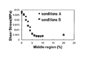
図7、図8は、このシミュレーション結果を示したもので、図7は、横軸が中間領域LMの形成幅(靴底用部材全体に占める中間領域LMの割合)を表し、縦軸が第1境界地点L1(軟質領域と中間領域との境界にあたる地点)に生じるせん断応力を表している。
また、図8は、横軸が中間領域LMの形成幅(靴底用部材全体に占める中間領域LMの割合)を表し、縦軸が第2境界地点L2(中間領域と硬質領域との境界にあたる地点)に生じるせん断応力を表している。
なお、図7、図8においてダイヤ形の凡例で示した結果が先の条件Aのもので、正方形で示した結果が先の条件Bのものである。
第1境界地点L1及び第2境界地点L2において生じる前記のせん断応力が高い値を示すということは靴底用部材に圧力を加えた際に強い反力を受けることを意味し、前記せん断応力が低い値を示すことが、境界部を挟んだ領域の硬さの違いによる違和感を使用者に感じさせ難いことを意味する。
即ち、前記せん断応力が低い値を示すことが、使用者にとって、快適性に優れることを意味する。
図7、図8からは、中間領域LMが僅かでも形成されると靴底用部材が快適性に優れたものになることがわかる。
次いで、靴底用部材を、硬さの異なる2種類のエチレン-酢酸ビニル共重合体(EVA)や硬さの異なる2種類の塩素化ポリエチレン(CPE)によって形成させた場合についてシミュレーションした。
なお、EVAに関しては、中敷領域IS、軟質領域LS、中間領域LM、及び、硬質領域LHが、下記表1に示した発泡体である場合についてシミュレーションした。
また、CPEに関しては、中敷領域IS、軟質領域LS、中間領域LM、及び、硬質領域LHが、下記表2、3に示した2通りでシミュレーションした。
なお、EVAに関しては、中敷領域IS、軟質領域LS、中間領域LM、及び、硬質領域LHが、下記表1に示した発泡体である場合についてシミュレーションした。
また、CPEに関しては、中敷領域IS、軟質領域LS、中間領域LM、及び、硬質領域LHが、下記表2、3に示した2通りでシミュレーションした。

これらの結果を、図9、図10に示す。
なお、図9、図10においてダイヤ形の凡例で示した結果が先の表1のEVAのもので、四角形で示した結果が表2のCPE、三角形で示した結果が表3のCPEのものである。
また、図9は、図7と同様に横軸が中間領域LMの形成幅を表し、縦軸が第1境界地点L1に生じるせん断応力を表している。
また、図10は、図8と同様に横軸が中間領域LMの形成幅を表し、縦軸が第2境界地点L2に生じるせん断応力を表している。
なお、図9、図10においてダイヤ形の凡例で示した結果が先の表1のEVAのもので、四角形で示した結果が表2のCPE、三角形で示した結果が表3のCPEのものである。
また、図9は、図7と同様に横軸が中間領域LMの形成幅を表し、縦軸が第1境界地点L1に生じるせん断応力を表している。
また、図10は、図8と同様に横軸が中間領域LMの形成幅を表し、縦軸が第2境界地点L2に生じるせん断応力を表している。
この図9、図10からも明らかなように、中間領域LMが形成されることで靴底用部材を快適性に優れたものとし得ること、及び、中間領域LMが5%以上形成されることで靴底用部材をより快適性に優れたものとし得ることについては、靴底用部材の形成材料などに関係なく発揮される。
以上のことからも、本発明によれば快適性に優れた靴の形成に有効な靴底用部材が提供され、ひいては、快適性に優れた靴が提供されることがわかる。
以上のことからも、本発明によれば快適性に優れた靴の形成に有効な靴底用部材が提供され、ひいては、快適性に優れた靴が提供されることがわかる。
1:靴、3:ミッドソール、4:アウターソール、31:第1部、32:第2部、33:第3部
Claims (11)
- 少なくとも第1ポリマー組成物と第2ポリマー組成物との2種類のポリマー組成物によって形成され、
前記第1ポリマー組成物によって形成された第1部と、前記第2ポリマー組成物によって形成された第2部とを備えており、
前記第1部と前記第2部との間に、前記第1ポリマー組成物と前記第2ポリマー組成物との混合物によって形成された第3部を備えている靴底用部材。 - 扁平形状を有し、水平方向において前記第1部と前記第2部とが前記第3部を介して隣接している請求項1記載の靴底用部材。
- シューセンター軸に直交する横断面での第1部の断面積をS11、第2部の断面積をS12、第3部の断面積をS13とした際に下記関係式(1)を満たす請求項2記載の靴底用部材。
5%≦〔100×S13/(S11+S12+S13)〕<100% ・・・(1)
- 前記第1部のアスカーC硬度が前記第2部のアスカーC硬度に比べて高い請求項3記載の靴底用部材。
- 第1部側から第2部側に向けて測定点を移動させて前記横断面における前記第3部のアスカーC硬度を測定した際に、該アスカーC硬度の値が前記移動の方向に向けて低下する請求項4記載の靴底用部材。
- 前記横断面における前記第3部のアスカーC硬度の値が、測定点を水平方向に移動させた場合、及び、垂直方向に移動させた場合の両方において変化する請求項3乃至5の何れか1項に記載の靴底用部材。
- 前記第1部が内足部に配され、前記第2部が前記第1部よりも外足部に配されている請求項2乃至6の何れか1項に記載の靴底用部材。
- シューセンター軸に平行する垂直面である縦断面における第1部の断面積をS21、第2部の断面積をS22、第3部の断面積をS23とした際に下記関係式(4)を満たす請求項2記載の靴底用部材。
5%≦〔100×S23/(S21+S22+S23)〕<100% ・・・(4)
- 前記第1部のアスカーC硬度が前記第2部のアスカーC硬度に比べて高い請求項8記載の靴底用部材。
- 第1部側から第2部側に向けて測定点を移動させて前記縦断面における前記第3部のアスカーC硬度を測定した際に、該アスカーC硬度の値が前記移動の方向に向けて低下する請求項9記載の靴底用部材。
- 請求項1乃至10の何れか1項に記載の靴底用部材を備えた靴。
Priority Applications (5)
| Application Number | Priority Date | Filing Date | Title |
|---|---|---|---|
| JP2016535745A JP6145579B1 (ja) | 2015-09-18 | 2015-09-18 | 靴底用部材、及び、靴 |
| US15/314,893 US11166521B2 (en) | 2015-09-18 | 2015-09-18 | Shoe sole member, method for producing the same, and shoe |
| PCT/JP2015/076782 WO2017046959A1 (ja) | 2015-09-18 | 2015-09-18 | 靴底用部材、及び、靴 |
| EP15892798.8A EP3165114B1 (en) | 2015-09-18 | 2015-09-18 | Shoe sole member and shoe |
| US17/491,747 US11576461B2 (en) | 2015-09-18 | 2021-10-01 | Shoe sole member, method for producing the same, and shoe |
Applications Claiming Priority (1)
| Application Number | Priority Date | Filing Date | Title |
|---|---|---|---|
| PCT/JP2015/076782 WO2017046959A1 (ja) | 2015-09-18 | 2015-09-18 | 靴底用部材、及び、靴 |
Related Child Applications (2)
| Application Number | Title | Priority Date | Filing Date |
|---|---|---|---|
| US15/314,893 A-371-Of-International US11166521B2 (en) | 2015-09-18 | 2015-09-18 | Shoe sole member, method for producing the same, and shoe |
| US17/491,747 Continuation US11576461B2 (en) | 2015-09-18 | 2021-10-01 | Shoe sole member, method for producing the same, and shoe |
Publications (1)
| Publication Number | Publication Date |
|---|---|
| WO2017046959A1 true WO2017046959A1 (ja) | 2017-03-23 |
Family
ID=58288479
Family Applications (1)
| Application Number | Title | Priority Date | Filing Date |
|---|---|---|---|
| PCT/JP2015/076782 WO2017046959A1 (ja) | 2015-09-18 | 2015-09-18 | 靴底用部材、及び、靴 |
Country Status (4)
| Country | Link |
|---|---|
| US (2) | US11166521B2 (ja) |
| EP (1) | EP3165114B1 (ja) |
| JP (1) | JP6145579B1 (ja) |
| WO (1) | WO2017046959A1 (ja) |
Cited By (2)
| Publication number | Priority date | Publication date | Assignee | Title |
|---|---|---|---|---|
| WO2019073609A1 (ja) | 2017-10-13 | 2019-04-18 | 株式会社アシックス | 靴底及びシューズ |
| CN110477520A (zh) * | 2019-09-10 | 2019-11-22 | 东莞市佳浩新材料有限公司 | 一种热熔胶膜复合鞋垫的生产工艺 |
Families Citing this family (4)
| Publication number | Priority date | Publication date | Assignee | Title |
|---|---|---|---|---|
| US20190126580A1 (en) * | 2017-10-31 | 2019-05-02 | Saucony, Inc. | Method and apparatus for manufacturing footwear soles |
| WO2019207569A1 (en) * | 2018-04-22 | 2019-10-31 | Insand Ltd. | Insole, insert, sole, and shoes and footwear having such components |
| CN108752728A (zh) * | 2018-06-25 | 2018-11-06 | 安徽省创安体育用品有限公司 | 一种提高发泡鞋底回弹性的加工方法 |
| WO2020142355A1 (en) * | 2018-12-31 | 2020-07-09 | Nike Innovate C.V. | Sole structure having differing hardness regions |
Citations (5)
| Publication number | Priority date | Publication date | Assignee | Title |
|---|---|---|---|---|
| JPS5997601U (ja) * | 1982-12-21 | 1984-07-02 | 株式会社アシックス | 運動靴底 |
| JPS6275703U (ja) * | 1985-06-18 | 1987-05-15 | ||
| JPH0379704U (ja) * | 1989-12-05 | 1991-08-14 | ||
| JPH05329005A (ja) * | 1992-05-30 | 1993-12-14 | Achilles Corp | 多重硬度靴底 |
| JP5433008B2 (ja) | 2008-09-26 | 2014-03-05 | ナイキ インターナショナル リミテッド | ファイロン・ビスケットを用いて局所的な硬さを有するミッドソールを製造するシステムおよび方法 |
Family Cites Families (6)
| Publication number | Priority date | Publication date | Assignee | Title |
|---|---|---|---|---|
| JP3020844B2 (ja) | 1995-08-21 | 2000-03-15 | アキレス株式会社 | 多層よりなるスラッシュ成形靴の製造方法 |
| DE202007018343U1 (de) | 2007-07-06 | 2008-05-15 | Spannrit Schuhkomponenten Gmbh | Schaumkunststoff-Schuheinlegesohle |
| US20110283560A1 (en) * | 2010-05-18 | 2011-11-24 | Montrail Corporation | Multiple response property footwear |
| JP5688168B2 (ja) * | 2011-03-18 | 2015-03-25 | コロンビア スポーツウエア ノース アメリカ、インコーポレイテッド | 高安定性複数密度ミッドソール |
| US20130340280A1 (en) * | 2012-06-21 | 2013-12-26 | Columbia Sportswear North America, Inc. | Foam for footwear midsole and the like |
| US9498927B2 (en) * | 2013-03-15 | 2016-11-22 | Nike, Inc. | Decorative foam and method |
-
2015
- 2015-09-18 WO PCT/JP2015/076782 patent/WO2017046959A1/ja active Application Filing
- 2015-09-18 US US15/314,893 patent/US11166521B2/en active Active
- 2015-09-18 EP EP15892798.8A patent/EP3165114B1/en active Active
- 2015-09-18 JP JP2016535745A patent/JP6145579B1/ja active Active
-
2021
- 2021-10-01 US US17/491,747 patent/US11576461B2/en active Active
Patent Citations (5)
| Publication number | Priority date | Publication date | Assignee | Title |
|---|---|---|---|---|
| JPS5997601U (ja) * | 1982-12-21 | 1984-07-02 | 株式会社アシックス | 運動靴底 |
| JPS6275703U (ja) * | 1985-06-18 | 1987-05-15 | ||
| JPH0379704U (ja) * | 1989-12-05 | 1991-08-14 | ||
| JPH05329005A (ja) * | 1992-05-30 | 1993-12-14 | Achilles Corp | 多重硬度靴底 |
| JP5433008B2 (ja) | 2008-09-26 | 2014-03-05 | ナイキ インターナショナル リミテッド | ファイロン・ビスケットを用いて局所的な硬さを有するミッドソールを製造するシステムおよび方法 |
Non-Patent Citations (1)
| Title |
|---|
| See also references of EP3165114A4 |
Cited By (2)
| Publication number | Priority date | Publication date | Assignee | Title |
|---|---|---|---|---|
| WO2019073609A1 (ja) | 2017-10-13 | 2019-04-18 | 株式会社アシックス | 靴底及びシューズ |
| CN110477520A (zh) * | 2019-09-10 | 2019-11-22 | 东莞市佳浩新材料有限公司 | 一种热熔胶膜复合鞋垫的生产工艺 |
Also Published As
| Publication number | Publication date |
|---|---|
| US11166521B2 (en) | 2021-11-09 |
| JP6145579B1 (ja) | 2017-06-14 |
| EP3165114B1 (en) | 2021-12-29 |
| US20220015501A1 (en) | 2022-01-20 |
| EP3165114A4 (en) | 2018-01-31 |
| JPWO2017046959A1 (ja) | 2017-09-14 |
| US11576461B2 (en) | 2023-02-14 |
| EP3165114A1 (en) | 2017-05-10 |
| US20180168282A1 (en) | 2018-06-21 |
Similar Documents
| Publication | Publication Date | Title |
|---|---|---|
| JP6145579B1 (ja) | 靴底用部材、及び、靴 | |
| EP2020879B1 (en) | Article of footwear with lightweight sole assembly | |
| JP5685343B2 (ja) | 発泡成形品、発泡ソール、及びシューズ | |
| KR100627143B1 (ko) | 입체형 신발 갑피용 가교발포 성형체 및 그 제조방법 | |
| JP6413031B2 (ja) | 靴用部材、靴、及びその製造方法 | |
| CN102320099A (zh) | 装有填有泡沫的元件的鞋类制品和用于制造填有泡沫的元件的方法 | |
| JP6395344B2 (ja) | 衝撃緩衝材、靴底用部材、靴、及び、スポーツ用保護具 | |
| JP6307667B2 (ja) | 靴底用部材、及び、靴 | |
| US11889888B2 (en) | Shoe sole member and shoe | |
| US11517075B2 (en) | Shoe sole member, shoe, and method for manufacturing shoe sole member | |
| JP4728112B2 (ja) | 靴 | |
| WO2022137394A1 (ja) | シューズ用の緩衝部材およびソール | |
| CZ22745U1 (cs) | Obuvnická stélka, zejména pro ortopedickou, diabetickou nebo sportovní obuv |
Legal Events
| Date | Code | Title | Description |
|---|---|---|---|
| ENP | Entry into the national phase |
Ref document number: 2016535745 Country of ref document: JP Kind code of ref document: A |
|
| REEP | Request for entry into the european phase |
Ref document number: 2015892798 Country of ref document: EP |
|
| WWE | Wipo information: entry into national phase |
Ref document number: 2015892798 Country of ref document: EP |
|
| WWE | Wipo information: entry into national phase |
Ref document number: 15314893 Country of ref document: US |
|
| NENP | Non-entry into the national phase |
Ref country code: DE |