WO2017043236A1 - Storage battery control device - Google Patents
Storage battery control device Download PDFInfo
- Publication number
- WO2017043236A1 WO2017043236A1 PCT/JP2016/073215 JP2016073215W WO2017043236A1 WO 2017043236 A1 WO2017043236 A1 WO 2017043236A1 JP 2016073215 W JP2016073215 W JP 2016073215W WO 2017043236 A1 WO2017043236 A1 WO 2017043236A1
- Authority
- WO
- WIPO (PCT)
- Prior art keywords
- allowable current
- battery
- current
- battery module
- storage battery
- Prior art date
Links
Images


Classifications
-
- H—ELECTRICITY
- H01—ELECTRIC ELEMENTS
- H01M—PROCESSES OR MEANS, e.g. BATTERIES, FOR THE DIRECT CONVERSION OF CHEMICAL ENERGY INTO ELECTRICAL ENERGY
- H01M10/00—Secondary cells; Manufacture thereof
- H01M10/42—Methods or arrangements for servicing or maintenance of secondary cells or secondary half-cells
- H01M10/425—Structural combination with electronic components, e.g. electronic circuits integrated to the outside of the casing
- H01M10/4257—Smart batteries, e.g. electronic circuits inside the housing of the cells or batteries
-
- B—PERFORMING OPERATIONS; TRANSPORTING
- B60—VEHICLES IN GENERAL
- B60L—PROPULSION OF ELECTRICALLY-PROPELLED VEHICLES; SUPPLYING ELECTRIC POWER FOR AUXILIARY EQUIPMENT OF ELECTRICALLY-PROPELLED VEHICLES; ELECTRODYNAMIC BRAKE SYSTEMS FOR VEHICLES IN GENERAL; MAGNETIC SUSPENSION OR LEVITATION FOR VEHICLES; MONITORING OPERATING VARIABLES OF ELECTRICALLY-PROPELLED VEHICLES; ELECTRIC SAFETY DEVICES FOR ELECTRICALLY-PROPELLED VEHICLES
- B60L3/00—Electric devices on electrically-propelled vehicles for safety purposes; Monitoring operating variables, e.g. speed, deceleration or energy consumption
-
- B—PERFORMING OPERATIONS; TRANSPORTING
- B60—VEHICLES IN GENERAL
- B60L—PROPULSION OF ELECTRICALLY-PROPELLED VEHICLES; SUPPLYING ELECTRIC POWER FOR AUXILIARY EQUIPMENT OF ELECTRICALLY-PROPELLED VEHICLES; ELECTRODYNAMIC BRAKE SYSTEMS FOR VEHICLES IN GENERAL; MAGNETIC SUSPENSION OR LEVITATION FOR VEHICLES; MONITORING OPERATING VARIABLES OF ELECTRICALLY-PROPELLED VEHICLES; ELECTRIC SAFETY DEVICES FOR ELECTRICALLY-PROPELLED VEHICLES
- B60L58/00—Methods or circuit arrangements for monitoring or controlling batteries or fuel cells, specially adapted for electric vehicles
- B60L58/10—Methods or circuit arrangements for monitoring or controlling batteries or fuel cells, specially adapted for electric vehicles for monitoring or controlling batteries
-
- G—PHYSICS
- G01—MEASURING; TESTING
- G01R—MEASURING ELECTRIC VARIABLES; MEASURING MAGNETIC VARIABLES
- G01R31/00—Arrangements for testing electric properties; Arrangements for locating electric faults; Arrangements for electrical testing characterised by what is being tested not provided for elsewhere
- G01R31/36—Arrangements for testing, measuring or monitoring the electrical condition of accumulators or electric batteries, e.g. capacity or state of charge [SoC]
- G01R31/367—Software therefor, e.g. for battery testing using modelling or look-up tables
-
- H—ELECTRICITY
- H01—ELECTRIC ELEMENTS
- H01M—PROCESSES OR MEANS, e.g. BATTERIES, FOR THE DIRECT CONVERSION OF CHEMICAL ENERGY INTO ELECTRICAL ENERGY
- H01M10/00—Secondary cells; Manufacture thereof
- H01M10/42—Methods or arrangements for servicing or maintenance of secondary cells or secondary half-cells
- H01M10/44—Methods for charging or discharging
-
- H—ELECTRICITY
- H02—GENERATION; CONVERSION OR DISTRIBUTION OF ELECTRIC POWER
- H02J—CIRCUIT ARRANGEMENTS OR SYSTEMS FOR SUPPLYING OR DISTRIBUTING ELECTRIC POWER; SYSTEMS FOR STORING ELECTRIC ENERGY
- H02J7/00—Circuit arrangements for charging or depolarising batteries or for supplying loads from batteries
-
- G—PHYSICS
- G01—MEASURING; TESTING
- G01R—MEASURING ELECTRIC VARIABLES; MEASURING MAGNETIC VARIABLES
- G01R31/00—Arrangements for testing electric properties; Arrangements for locating electric faults; Arrangements for electrical testing characterised by what is being tested not provided for elsewhere
- G01R31/36—Arrangements for testing, measuring or monitoring the electrical condition of accumulators or electric batteries, e.g. capacity or state of charge [SoC]
- G01R31/3644—Constructional arrangements
- G01R31/3647—Constructional arrangements for determining the ability of a battery to perform a critical function, e.g. cranking
-
- G—PHYSICS
- G01—MEASURING; TESTING
- G01R—MEASURING ELECTRIC VARIABLES; MEASURING MAGNETIC VARIABLES
- G01R31/00—Arrangements for testing electric properties; Arrangements for locating electric faults; Arrangements for electrical testing characterised by what is being tested not provided for elsewhere
- G01R31/36—Arrangements for testing, measuring or monitoring the electrical condition of accumulators or electric batteries, e.g. capacity or state of charge [SoC]
- G01R31/392—Determining battery ageing or deterioration, e.g. state of health
-
- H—ELECTRICITY
- H01—ELECTRIC ELEMENTS
- H01M—PROCESSES OR MEANS, e.g. BATTERIES, FOR THE DIRECT CONVERSION OF CHEMICAL ENERGY INTO ELECTRICAL ENERGY
- H01M10/00—Secondary cells; Manufacture thereof
- H01M10/42—Methods or arrangements for servicing or maintenance of secondary cells or secondary half-cells
- H01M10/48—Accumulators combined with arrangements for measuring, testing or indicating the condition of cells, e.g. the level or density of the electrolyte
-
- H—ELECTRICITY
- H01—ELECTRIC ELEMENTS
- H01M—PROCESSES OR MEANS, e.g. BATTERIES, FOR THE DIRECT CONVERSION OF CHEMICAL ENERGY INTO ELECTRICAL ENERGY
- H01M10/00—Secondary cells; Manufacture thereof
- H01M10/42—Methods or arrangements for servicing or maintenance of secondary cells or secondary half-cells
- H01M10/425—Structural combination with electronic components, e.g. electronic circuits integrated to the outside of the casing
- H01M2010/4271—Battery management systems including electronic circuits, e.g. control of current or voltage to keep battery in healthy state, cell balancing
Definitions
- the present invention relates to a storage battery control device.
- Patent Document 1 discloses a technique for setting an upper limit value of current in accordance with the degree of deterioration of a storage battery.
- the magnitude of the current that should be output from the in-vehicle battery system varies depending on the situation as well as the degree of deterioration of the storage battery. For example, depending on the running state of the vehicle, it may be necessary to temporarily pass a large current through the load. In such a case, since the influence on the deterioration of the storage battery is small for a short time, it is preferable to temporarily increase the upper limit value of the current. However, in the conventional technique described in Patent Document 1, since the upper limit value of the current is set according to the degree of deterioration of the storage battery, it is difficult to appropriately control the current of the storage battery according to the situation.
- the storage battery control device includes a battery information acquisition unit that acquires storage battery information, and a first allowable current that calculates a first allowable current of the storage battery in accordance with a rated value of a component through which current flows due to charging and discharging of the storage battery.
- a third allowable current calculation unit that calculates a third allowable current of the storage battery according to a deterioration state of the storage battery based on the information acquired by the unit.
- the current of the storage battery can be appropriately controlled according to the situation.
- FIG. 1 is a diagram showing a configuration of a battery system to which a storage battery control device according to an embodiment of the present invention is applied.
- a battery system 100 shown in FIG. 1 is connected to an inverter 110 and a host controller 112.
- a load 111 is connected to the inverter 110.
- the inverter 110 is a bidirectional inverter that operates under the control of the host controller 112.
- the inverter 110 converts the DC power supplied from the battery system 100 into AC power and outputs the AC power to the load 111.
- the load 111 is, for example, a three-phase AC motor mounted on the vehicle, and generates driving force of the vehicle by being rotationally driven using AC power supplied from the inverter 110. Further, when regenerative power generation is performed by operating the load 111 as a generator using the kinetic energy of the vehicle, AC power is output from the load 111. In this case, the inverter 110 converts AC power output from the load 111 into DC power, and outputs and stores the obtained DC power to the battery system 100. Thus, the battery system 100 is charged and discharged by operating the inverter 110 in accordance with the control of the host controller 112.
- the present invention is not limited to the configuration shown in FIG. 1 as long as the charging / discharging of the battery system 100 can be appropriately controlled.
- a charging system different from the inverter 110 may be connected to the battery system 100, and the battery system 100 may be charged as necessary using this charging system.
- the battery system 100 includes a battery module 101, a current sensor 102, a voltage sensor 103, a temperature sensor 104, a leakage sensor 105, a relay 106A, a relay 106B, and a battery controller 107.
- the battery module 101 is a chargeable / dischargeable storage battery configured by connecting a plurality of unit batteries in series or series-parallel.
- the battery modules 101 may be divided into two or more groups, and a breaker that can be operated manually is provided between the groups. If it does in this way, generation
- the current sensor 102 detects the charge / discharge current flowing through the battery module 101.
- the voltage sensor 103 detects the voltage of the battery module 101.
- the temperature sensor 104 detects the temperature of the battery module 101.
- the earth leakage sensor 105 detects the insulation resistance of the battery module 101. The detection results of the current sensor 102, the voltage sensor 103, the temperature sensor 104, and the leakage sensor 105 are output to the battery controller 107, respectively.
- Relays 106A and 106B are for switching the electrical connection state between the battery module 101 and the inverter 110, and are controlled by the battery controller 107 or the host controller 112.
- Relay 106 ⁇ / b> A is connected between the positive side of battery module 101 and inverter 110
- relay 106 ⁇ / b> B is connected between the negative side of battery module 101 and inverter 110.
- either one of the relays 106A and 106B may be omitted.
- a precharge relay and a resistor may be provided in parallel with the relay 106A or 106B. In this case, when the battery module 101 and the inverter 110 are connected, the precharge relay may be turned on first, and after the current becomes sufficiently small, the relay 106A or 106B may be turned on to turn off the precharge relay.
- the battery controller 107 corresponds to a storage battery control device according to an embodiment of the present invention.
- the battery controller 107 acquires the detection results of the current sensor 102, the voltage sensor 103, the temperature sensor 104, and the leakage sensor 105, and controls the battery system 100 based on these detection results. For example, the battery controller 107 determines the state of charge (SOC: State Of Charge) or the deterioration state (SOH :) of the battery module 101 based on the detection result of the charge / discharge current by the current sensor 102 or the detection result of the voltage by the voltage sensor 103. State Of Health) is calculated.
- SOC State Of Charge
- SOH deterioration state
- charge / discharge control of the battery module 101 Based on these calculation results, charge / discharge control of the battery module 101, balancing control for equalizing the SOC of each unit battery of the battery module 101, and the like are performed. Further, the battery controller 107 determines whether or not the battery module 101 is in a leakage state or a state where leakage is likely to occur based on the detection result of the insulation resistance by the leakage sensor 105, and when determining that the battery module 101 is in these states. Stops the operation of the battery system 100. In addition to this, the battery controller 107 can execute various processes.
- the battery controller 107 calculates an allowable current for appropriately controlling the current flowing through the battery module 101 according to the situation, and outputs it to the host controller 112. Details of charge / discharge control of the battery module 101 by the battery controller 107 will be described in detail later.
- the host controller 112 controls the operation state of the battery system 100 and the inverter 110 based on various information of the battery module 101 transmitted from the battery controller 107.
- FIG. 2 is a functional block diagram of the battery controller 107.
- the battery controller 107 includes functions of a battery information acquisition unit 201, a first allowable current calculation unit 202, a second allowable current calculation unit 203, a third allowable current calculation unit 204, and an allowable current selection unit 205. Consists of blocks.
- the battery controller 107 can implement these functional blocks by executing a predetermined program by the CPU, for example.
- the battery information acquisition unit 201 acquires various information related to the state of the battery module 101 based on the detection results of the current sensor 102, the voltage sensor 103, and the temperature sensor 104.
- the battery information acquisition unit 201 acquires, for example, the charge / discharge current of the battery module 101 detected by the current sensor 102, the temperature of the battery module 101 detected by the temperature sensor 104, and the like as information of the battery module 101.
- the usage time of the battery module 101 measured using a timer (not shown) built in the battery controller 107, the travel distance of the vehicle on which the battery module 101 is mounted, and the like may be acquired as information of the battery module 101. it can. That is, the battery information acquisition unit 201 can acquire at least one piece of information from various information related to the state of the battery module 101 as described above. Information other than those listed above may be acquired as information on the battery module 101.
- the first allowable current calculation unit 202 calculates the first allowable current of the battery module 101.
- the first allowable current is the allowable current of the battery module 101 according to the rated value of the component through which current flows due to charging / discharging of the battery module 101. A specific method of calculating the first allowable current by the first allowable current calculation unit 202 will be described later with reference to FIGS. 3 and 4.
- the second allowable current calculation unit 203 calculates the second allowable current of the battery module 101 based on the information of the battery module 101 acquired by the battery information acquisition unit 201.
- the second allowable current is an allowable current of the battery module 101 according to the SOC of the battery module 101. A specific method of calculating the second allowable current by the second allowable current calculation unit 203 will be described later with reference to FIGS.
- the third allowable current calculation unit 204 calculates the third allowable current of the battery module 101 based on the information of the battery module 101 acquired by the battery information acquisition unit 201.
- the third allowable current is an allowable current of the battery module 101 according to the SOH of the battery module 101. A specific method of calculating the third allowable current by the third allowable current calculation unit 204 will be described later with reference to FIG.
- the allowable current selection unit 205 includes the first allowable current, the second allowable current, or the third allowable current calculated by the first allowable current calculation unit 202, the second allowable current calculation unit 203, and the third allowable current calculation unit 204, respectively. Choose one. A specific method for selecting the allowable current by the allowable current selection unit 205 will be described later. Then, the selected allowable current value is output to the host controller 112. When the allowable current is output from the allowable current selection unit 205, the host controller 112 controls the battery system 100 and the inverter 110 according to the value of the allowable current, and performs charge / discharge control of the battery module 101.
- FIG. 3 is a functional block diagram of the first allowable current calculation unit 202.
- the first allowable current calculation unit 202 includes functional blocks of a rated value acquisition unit 301 and a first allowable current determination unit 302.
- the rated value acquisition unit 301 acquires the current rated value of each component through which current flows due to charging / discharging of the battery module 101 among the various electrical components constituting the battery system 100 as the rated value related to the first allowable current.
- the rated value acquisition unit 301 is a current rating value for various components such as a bus bar, a connector, a current cable, a relay (switch), a fuse, and a screw that are arranged on the charge / discharge current path in the battery system 100, for example. To get.
- shunt resistance, adhesive resin, etc. are arrange
- the rated value acquisition unit 301 stores, for example, the temperature characteristics of the current rated value of each component in advance. And based on the temperature of the battery module 101 detected by the temperature sensor 104, the temperature of each component is estimated, and the current rating value according to the temperature is acquired for each component. At this time, the degradation state of each component may be estimated based on the usage history of the battery system 100 and the current rating value of each component may be determined in consideration of the estimation result.
- the first allowable current determining unit 302 determines the first allowable current based on the current rated value of each component acquired by the rated value acquiring unit 301. For example, the first allowable current determining unit 302 determines the first allowable current in accordance with the component having the smallest current rating value.
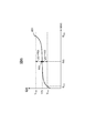
- FIG. 4 is a diagram for explaining a method of determining the first allowable current by the first allowable current determining unit 302.
- straight lines 401, 402, and 403 represent current rated value characteristic examples with respect to energization times of different components.
- the components of the battery system 100 have a constant current rating value regardless of the energization time as indicated by a straight line 401, or the energization time becomes longer (as the energization duty increases) as indicated by the straight lines 402 and 403, respectively.
- the first allowable current determining unit 302 determines the first allowable current according to the characteristics of the current rated value with respect to the energization time as indicated by the broken line 404, for example. be able to.
- FIG. 5 is a functional block diagram of the second allowable current calculation unit 203.
- the second allowable current calculation unit 203 includes functional blocks of an SOC calculation unit 501, an internal resistance calculation unit 502, and a second allowable current determination unit 503.
- the SOC calculation unit 501 calculates the SOC of the battery module 101 based on the detection result of the charge / discharge current by the current sensor 102 and the detection result of the voltage by the voltage sensor 103. For example, the SOC calculation unit 501 can obtain the SOC from the integrated value of the charge / discharge current, or can obtain the SOC from the open circuit voltage (OCV) when the battery module 101 is not charged / discharged.
- OCV open circuit voltage
- the internal resistance calculation unit 502 calculates the internal resistance value of the battery module 101 based on the SOC obtained by the SOC calculation unit 501. For example, the internal resistance calculation unit 502 determines the internal resistance of the battery module 101 based on the OCV obtained from the SOC, the detection result of the charge / discharge current by the current sensor 102, and the voltage detection result at the time of charge / discharge by the voltage sensor 103. The value can be calculated. At this time, the internal resistance value of the battery module 101 may be obtained in consideration of the temperature detected by the temperature sensor 104.
- the second allowable current determining unit 503 determines the second allowable current based on the SOC obtained by the SOC computing unit 501 and the internal resistance obtained by the internal resistance computing unit 502.
- FIG. 6 is a diagram for explaining a method of determining the second allowable current by the second allowable current determining unit 503.
- a curve 601 shows an example of an SOC-OCV curve representing the relationship between the SOC and OCV of the battery module 101.
- Smax the maximum SOC value used by the battery module 101
- Smin the minimum value
- Smin the OCV maximum value Vmax and minimum value Vmin of the battery module 101 are represented by an SOC-OCV curve 601 as shown in FIG. It is calculated
- the second allowable current determination unit 503 determines the second allowable current by obtaining the allowable charging current Ic (t) and the allowable discharge current Id (t) based on the above formulas (2) and (3). can do.
- FIG. 7 is a functional block diagram of the third allowable current calculation unit 204.
- the third allowable current calculation unit 204 includes functional blocks of an SOH calculation unit 701, a life prediction unit 702, and a third allowable current determination unit 703.
- the SOH calculation unit 701 calculates the SOH of the battery module 101 based on the charge / discharge current detection result by the current sensor 102 and the voltage detection result by the voltage sensor 103. Note that the calculation results of the SOC and internal resistance may be acquired from the second allowable current calculation unit 203, and the SOH may be calculated based on these calculation results.
- the lifetime predicting unit 702 predicts the lifetime of the battery module 101 based on the SOH calculated by the SOH calculating unit 701. For example, the life prediction unit 702 records a history of information on the battery module 101 acquired by the battery information acquisition unit 201 in association with the SOH of the battery module 101. By estimating the future transition of the SOH based on the information thus recorded, it is possible to calculate the deterioration progress rate of the battery module 101 and predict the life from the calculation result.
- the third allowable current determination unit 703 determines the third allowable current based on the SOH obtained by the SOH calculation unit 701 and the life obtained by the life prediction unit 702. For example, the third allowable current determination unit 703 compares the lifetime of the battery module 101 predicted by the lifetime prediction unit 702 with a preset lifetime target value. As a result, if the deviation between the target life value and the predicted life value is large, the value of the third allowable current is adjusted so that the deviation is small. Thereby, the third allowable current calculation unit 204 can calculate a third allowable current according to the SOH of the battery module 101.
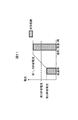
- FIG. 8 is a diagram for explaining a method of determining the third allowable current by the third allowable current determining unit 703.
- a curve 801 shows an example of the relationship between the deterioration progress rate and the third allowable current.
- the third allowable current determination unit 703 stores, for example, data in which the relationship of FIG. 8 obtained in advance through experiments or the like is mapped. By using this data, the third allowable current determination unit 703 can determine the third allowable current in accordance with the deterioration progress rate of the battery module 101.
- FIG. 9 is a flowchart of charge / discharge control of the battery module 101 by the battery controller 107.
- the battery controller 107 executes charge / discharge control of the battery module 101 at predetermined processing cycles according to the flowchart of FIG.
- step S101 the battery controller 107 uses the battery information acquisition unit 201 to acquire various types of information on the battery module 101 as described above.
- step S102 the battery controller 107 uses the first allowable current calculation unit 202 to calculate the first allowable current of the battery module 101 based on the information of the battery module 101 acquired in step S101.
- step S103 the battery controller 107 calculates the second allowable current of the battery module 101 based on the information of the battery module 101 acquired in step S101 by the second allowable current calculation unit 203.
- step S104 the battery controller 107 calculates the third allowable current of the battery module 101 based on the information of the battery module 101 acquired in step S101 by the third allowable current calculation unit 204.
- step S105 the battery controller 107 uses the allowable current selection unit 205 to compare the calculation results in steps S102 to S104. That is, the first allowable current calculated in step S102, the second allowable current calculated in step S103, and the third allowable current calculated in step S104 are compared, and the magnitude relationship between them is grasped.
- step S106 the battery controller 107 determines whether or not the first allowable current is lower than either the second allowable current or the third allowable current based on the comparison result in step S105 by the allowable current selection unit 205. . As a result, when the determination condition is satisfied, that is, when the first allowable current is the lowest, the process proceeds to step S109. On the other hand, if the determination condition is not satisfied, that is, if the first allowable current is higher than at least one of the second allowable current and the third allowable current, the process proceeds to step S106.
- step S107 the battery controller 107 causes the allowable current selection unit 205 to determine whether the second allowable current is lower than either the first allowable current or the third allowable current based on the comparison result in step S105. .
- the determination condition is satisfied, that is, when the second allowable current is the lowest, the process proceeds to step S111.
- the determination condition is not satisfied, that is, if the second allowable current is higher than at least one of the first allowable current and the third allowable current, the process proceeds to step S108.
- step S108 the battery controller 107 determines whether or not the current situation is a situation where priority should be given to suppression of deterioration of the battery module 101 by the allowable current selection unit 205. For example, when the battery system 100 is set in a mode where priority should be given to the life of the battery module 101 or when the load of the battery module 101 is small, such as during vehicle cruising, the allowable current selection unit 205 It is determined that priority should be given to suppression of deterioration of the module 101.
- the allowable current selection unit 205 is, for example, when the battery system 100 is set to a mode where priority should be given to the running performance and fuel consumption of the vehicle, or when the load of the battery module 101 is heavy such as during vehicle acceleration Determines that priority should not be given to suppression of deterioration of the battery module 101.
- the battery system 100 is mounted on an electric vehicle such as a hybrid vehicle. In such a case, when the vehicle travels on an approach road or uphill road to the highway, or when overtaking traveling, the driver steps on the accelerator to increase the output torque from the load 111 that is an electric motor. May require improvement.
- the allowable current selection unit 205 determines whether or not there is such an output improvement request based on the amount of change in the accelerator opening, and when determining that the output improvement request has been made, the charge / discharge performance of the battery module 101 is prioritized. Therefore, it can be determined that deterioration suppression should not be given priority.
- the determination in step S108 can be performed using various determination conditions. As a result, if it is determined that degradation should be prioritized, the process proceeds to step S112. On the other hand, if it is determined that deterioration suppression should not be prioritized, the process proceeds to step S109.
- step S109 the battery controller 107 causes the allowable current selection unit 205 to determine whether the first allowable current is lower than the second allowable current based on the comparison result in step S105. As a result, when the first allowable current is lower than the second allowable current, the process proceeds to step S110. Conversely, when the first allowable current is equal to or larger than the second allowable current, the process proceeds to step S111. .
- step S110 the battery controller 107 selects the first allowable current obtained in step S102 by the allowable current selection unit 205 and outputs it to the host controller 112. That is, the battery controller 107 is not in a situation where the first allowable current is lower than the second allowable current and the third allowable current, or in a situation where deterioration suppression should be prioritized, and the first allowable current is lower than the second allowable current. In that case, step S110 is executed. Accordingly, the first allowable current is selected as the allowable current in the charge / discharge control of the battery module 101.
- step S111 the battery controller 107 selects the second allowable current obtained in step S103 by the allowable current selection unit 205 and outputs the second allowable current to the host controller 112. That is, the battery controller 107 is not in a situation where the second allowable current is lower than the first allowable current and the third allowable current, or in a situation where deterioration suppression should not be given priority, and the second allowable current is lower than the first allowable current. In that case, step S111 is executed. Accordingly, the second allowable current is selected as the allowable current in the charge / discharge control of the battery module 101.
- step S112 the battery controller 107 uses the allowable current selection unit 205 to select the third allowable current obtained in step S104 and output it to the host controller 112. That is, the battery controller 107 executes step S112 when it is a situation where priority should be given to deterioration suppression. Thereby, the third allowable current is selected as the allowable current in the charge / discharge control of the battery module 101.
- the battery controller 107 After executing any of steps S110 to S112, the battery controller 107 ends the process shown in the flowchart of FIG.
- FIG. 10 shows an example of a change in allowable current when the conventional technique is used.
- the safety of parts, the safety of the storage battery, the life of the storage battery, etc. like the first allowable current, the second allowable current and the third allowable current described above.
- charge / discharge control cannot be performed exceeding this minimum allowable current. Therefore, as shown in FIG.
- the magnitude relationship between the allowable currents is different between the low temperature and the normal temperature, and in the case where the third allowable current is lower than the first and second allowable currents at the normal temperature, the charging / discharging current is temporary. Although there is no problem even if the third allowable current is exceeded, charge / discharge control is always performed according to the minimum allowable current. As a result, it is impossible to perform charge / discharge utilizing the range that can be originally used at room temperature, and the performance of the battery system cannot be maximized when necessary.
- FIG. 11 shows an example of a change in allowable current when the present invention is used.
- the first, second and third allowable currents determined from different viewpoints can be used properly according to the situation. Therefore, in the case described above, when an output improvement request is made to the battery system 100, as shown in FIG. 11, the smaller of the first allowable current or the second allowable current is temporarily set as the allowable current. It is possible to increase the allowable current. As a result, it is possible to make maximum use of the charge / discharge performance of the battery system.
- FIG. 12 shows an example of a change in allowable current when the present invention is more actively used.
- the battery system 100 is mounted on an electric vehicle such as a hybrid vehicle, and the driver can select a mode that prioritizes the life of the battery module 101 and a mode that prioritizes driving performance such as fuel efficiency and acceleration performance.
- the battery system 100 sets the third allowable current as the allowable current, and when the driver selects the driving performance priority mode, the first or second The smaller allowable current is the allowable current.
- a method of selecting the allowable current according to the driver's selection can be adopted.
- the battery controller 107 includes a battery information acquisition unit 201, a first allowable current calculation unit 202, a second allowable current calculation unit 203, and a third allowable current calculation unit 204.
- the battery information acquisition unit 201 acquires information on the battery module 101 that is a storage battery (step S101).
- the first allowable current calculation unit 202 calculates the first allowable current of the battery module 101 according to the rated value of the component through which current flows due to charging / discharging of the battery module 101 (step S102).
- the second allowable current calculation unit 203 calculates the second allowable current of the battery module 101 according to the SOC of the battery module 101 based on the information acquired by the battery information acquisition unit 201 (step S103).
- the third allowable current calculation unit 204 calculates the third allowable current of the battery module 101 according to the SOH of the battery module 101 based on the information acquired by the battery information acquisition unit 201 (step S104). Since it did in this way, based on the calculation result of these allowable currents, the electric current of the battery module 101 can be appropriately controlled according to the situation.
- the battery controller 107 further includes an allowable current selection unit 205 that selects and outputs one of the first allowable current, the second allowable current, and the third allowable current. Since it did in this way, a suitable allowable current can be selected according to a condition, and it can use for charging / discharging control of the battery module 101.
- FIG. 1 An allowable current selection unit 205 that selects and outputs one of the first allowable current, the second allowable current, and the third allowable current. Since it did in this way, a suitable allowable current can be selected according to a condition, and it can use for charging / discharging control of the battery module 101.
- the allowable current selection unit 205 selects the first allowable current (step S110), and the second allowable current If the current is lower than the first allowable current and the third allowable current, the second allowable current is selected (step S111). Since it did in this way, when either the 1st allowable current or the 2nd allowable current is the lowest, charging / discharging control of the battery module 101 can be performed according to the allowable current. Therefore, failure prevention of the battery system 100 and performance maintenance of the battery module 101 can be achieved.
- the allowable current selection unit 205 determines whether or not priority should be given to suppression of deterioration of the battery module 101 (step S108). As a result, if it is determined that priority should be given to suppression of deterioration of the battery module 101, the third allowable current is selected (step S112), and determination is not made that priority should be given to suppression of deterioration of the battery module 101. If so, the first allowable current or the second allowable current is selected (steps S110 and S111). Since it did in this way, when it is the situation which should give priority to deterioration suppression of the battery module 101, charging / discharging control of the battery module 101 can be performed according to a 3rd permissible current. Therefore, it is possible to suppress the deterioration of the battery module 101 and to ensure the lifetime.
- the battery controller 107 includes the allowable current selection unit 205
- the function of the allowable current selection unit 205 may be realized by the host controller 112.
- the battery controller 107 executes the processing of steps S101 to S104 in FIG. 9, and outputs the obtained values of the first allowable current, the second allowable current, and the third allowable current to the host controller 112.
- the host controller 112 executes the processing of steps S105 to S112 to select one of the first allowable current, the second allowable current, and the third allowable current. .
- charge / discharge control of the battery module 101 is performed according to the selected allowable current. Even if it does in this way, there can exist an effect similar to the above.
- SYMBOLS 100 Battery system 101: Battery module 102: Current sensor 103: Voltage sensor 104: Temperature sensor 105: Leakage sensor 106A, 106B: Relay 107: Battery controller 110: Inverter 111: Load 112: High-order controller 201: Battery information acquisition part 202 : First allowable current calculation unit 203: second allowable current calculation unit 204: third allowable current calculation unit 205: allowable current selection unit
Landscapes
- Engineering & Computer Science (AREA)
- Manufacturing & Machinery (AREA)
- General Chemical & Material Sciences (AREA)
- Electrochemistry (AREA)
- Chemical Kinetics & Catalysis (AREA)
- Chemical & Material Sciences (AREA)
- Power Engineering (AREA)
- Microelectronics & Electronic Packaging (AREA)
- Physics & Mathematics (AREA)
- General Physics & Mathematics (AREA)
- Mechanical Engineering (AREA)
- Transportation (AREA)
- Life Sciences & Earth Sciences (AREA)
- Sustainable Energy (AREA)
- Sustainable Development (AREA)
- Secondary Cells (AREA)
- Charge And Discharge Circuits For Batteries Or The Like (AREA)
- Electric Propulsion And Braking For Vehicles (AREA)
Abstract
The present invention appropriately controls the current of a storage battery according to the situation. In a battery controller 107, a battery information acquiring unit 201 acquires information about a storage battery. A first allowable current calculating unit 202 calculates a first allowable current of a battery module 101 according to the rated values of components through which current flows by charge/discharge of the battery module 101. A second allowable current calculating unit 203 calculates a second allowable current of the battery module 101 according to the SOC of the battery module 101, on the basis of information acquired by the battery information acquiring unit 201. A third allowable current calculating unit 204 calculates a third allowable current of the battery module 101 according to the SOH of the battery module 101, on the basis of information acquired by the battery information acquiring unit 201.
Description
本発明は、蓄電池制御装置に関する。
The present invention relates to a storage battery control device.
従来、HEV(ハイブリッド自動車)やPHEV(プラグインハイブリッド自動車)に搭載され、蓄電池にリチウムイオン二次電池を用いた車載用電池システムが使用されている。こうした車載用電池システムでは、構成部品の安全性や劣化防止の観点から、蓄電池に流れる電流を所定範囲内に制限することが必要である。たとえば特許文献1では、蓄電池の劣化度に応じて電流の上限値を設定する技術が開示されている。
Conventionally, an in-vehicle battery system that is mounted on HEV (hybrid vehicle) or PHEV (plug-in hybrid vehicle) and uses a lithium ion secondary battery as a storage battery has been used. In such an in-vehicle battery system, it is necessary to limit the current flowing through the storage battery within a predetermined range from the viewpoint of safety of components and prevention of deterioration. For example, Patent Document 1 discloses a technique for setting an upper limit value of current in accordance with the degree of deterioration of a storage battery.
車載用電池システムから出力すべき電流の大きさは、蓄電池の劣化度だけでなく、状況によっても様々に変化する。たとえば、車両の走行状態等によっては、一時的に大きな電流を負荷に流す必要が生じる場合がある。このような場合には、短時間であれば蓄電池の劣化への影響は小さいため、電流の上限値を一時的に上昇することが好ましい。しかし、特許文献1に記載の従来技術では、蓄電池の劣化度に応じて電流の上限値が設定されるため、蓄電池の電流を状況に応じて適切に制御することが困難であった。
The magnitude of the current that should be output from the in-vehicle battery system varies depending on the situation as well as the degree of deterioration of the storage battery. For example, depending on the running state of the vehicle, it may be necessary to temporarily pass a large current through the load. In such a case, since the influence on the deterioration of the storage battery is small for a short time, it is preferable to temporarily increase the upper limit value of the current. However, in the conventional technique described in Patent Document 1, since the upper limit value of the current is set according to the degree of deterioration of the storage battery, it is difficult to appropriately control the current of the storage battery according to the situation.
本発明による蓄電池制御装置は、蓄電池の情報を取得する電池情報取得部と、前記蓄電池の充放電により電流が流れる構成部品の定格値に応じた前記蓄電池の第1許容電流を演算する第1許容電流演算部と、前記電池情報取得部により取得された前記情報に基づいて、前記蓄電池の充電状態に応じた前記蓄電池の第2許容電流を演算する第2許容電流演算部と、前記電池情報取得部により取得された前記情報に基づいて、前記蓄電池の劣化状態に応じた前記蓄電池の第3許容電流を演算する第3許容電流演算部と、を備える。
The storage battery control device according to the present invention includes a battery information acquisition unit that acquires storage battery information, and a first allowable current that calculates a first allowable current of the storage battery in accordance with a rated value of a component through which current flows due to charging and discharging of the storage battery. A current calculation unit; a second allowable current calculation unit that calculates a second allowable current of the storage battery according to a state of charge of the storage battery based on the information acquired by the battery information acquisition unit; and the battery information acquisition. A third allowable current calculation unit that calculates a third allowable current of the storage battery according to a deterioration state of the storage battery based on the information acquired by the unit.
本発明によれば、蓄電池の電流を状況に応じて適切に制御することができる。
According to the present invention, the current of the storage battery can be appropriately controlled according to the situation.
以下、図面を参照して本発明の一実施形態を説明する。
Hereinafter, an embodiment of the present invention will be described with reference to the drawings.
図1は、本発明の一実施形態に係る蓄電池制御装置を適用した電池システムの構成を示す図である。図1に示す電池システム100は、インバータ110および上位コントローラ112と接続されている。インバータ110には負荷111が接続されている。
FIG. 1 is a diagram showing a configuration of a battery system to which a storage battery control device according to an embodiment of the present invention is applied. A battery system 100 shown in FIG. 1 is connected to an inverter 110 and a host controller 112. A load 111 is connected to the inverter 110.
インバータ110は、上位コントローラ112の制御により動作する双方向インバータである。インバータ110は、電池システム100から供給される直流電力を交流電力に変換して負荷111に出力する。負荷111は、たとえば車両に搭載される三相交流電動機であり、インバータ110から供給される交流電力を用いて回転駆動することで車両の駆動力を発生する。また、車両の運動エネルギーを利用して負荷111を発電機として動作させることで回生発電を行うと、負荷111から交流電力が出力される。この場合、インバータ110は、負荷111から出力された交流電力を直流電力に変換し、得られた直流電力を電池システム100に出力して蓄える。こうして上位コントローラ112の制御に応じてインバータ110を動作させることにより、電池システム100の充放電が行われる。
The inverter 110 is a bidirectional inverter that operates under the control of the host controller 112. The inverter 110 converts the DC power supplied from the battery system 100 into AC power and outputs the AC power to the load 111. The load 111 is, for example, a three-phase AC motor mounted on the vehicle, and generates driving force of the vehicle by being rotationally driven using AC power supplied from the inverter 110. Further, when regenerative power generation is performed by operating the load 111 as a generator using the kinetic energy of the vehicle, AC power is output from the load 111. In this case, the inverter 110 converts AC power output from the load 111 into DC power, and outputs and stores the obtained DC power to the battery system 100. Thus, the battery system 100 is charged and discharged by operating the inverter 110 in accordance with the control of the host controller 112.
なお、電池システム100の充放電を適切に制御することができれば、本発明は図1の構成に限定されない。たとえば、インバータ110とは別の充電システムを電池システム100に接続し、この充電システムを用いて電池システム100の充電を必要に応じて行うようにしてもよい。
Note that the present invention is not limited to the configuration shown in FIG. 1 as long as the charging / discharging of the battery system 100 can be appropriately controlled. For example, a charging system different from the inverter 110 may be connected to the battery system 100, and the battery system 100 may be charged as necessary using this charging system.
電池システム100は、電池モジュール101、電流センサ102、電圧センサ103、温度センサ104、漏電センサ105、リレー106A、リレー106B、およびバッテリコントローラ107を備える。
The battery system 100 includes a battery module 101, a current sensor 102, a voltage sensor 103, a temperature sensor 104, a leakage sensor 105, a relay 106A, a relay 106B, and a battery controller 107.
電池モジュール101は、複数個の単位電池を直列または直並列に接続して構成されている充放電可能な蓄電池である。なお、電池モジュール101を2つ以上のグループに分け、各グループ間に人力で操作可能な遮断器を設けてもよい。このようにすれば、電池システム100の組み立て、解体、点検等の作業時には遮断器を開放することで、感電事故や短絡事故の発生を防ぐことができる。
The battery module 101 is a chargeable / dischargeable storage battery configured by connecting a plurality of unit batteries in series or series-parallel. The battery modules 101 may be divided into two or more groups, and a breaker that can be operated manually is provided between the groups. If it does in this way, generation | occurrence | production of an electric shock accident and a short circuit accident can be prevented by open | releasing a circuit breaker at the time of work, such as an assembly of the battery system 100, a disassembly, and an inspection.
電流センサ102は、電池モジュール101に流れる充放電電流を検出する。電圧センサ103は、電池モジュール101の電圧を検出する。温度センサ104は、電池モジュール101の温度を検出する。漏電センサ105は、電池モジュール101の絶縁抵抗を検出する。電流センサ102、電圧センサ103、温度センサ104および漏電センサ105の各検出結果は、バッテリコントローラ107にそれぞれ出力される。
The current sensor 102 detects the charge / discharge current flowing through the battery module 101. The voltage sensor 103 detects the voltage of the battery module 101. The temperature sensor 104 detects the temperature of the battery module 101. The earth leakage sensor 105 detects the insulation resistance of the battery module 101. The detection results of the current sensor 102, the voltage sensor 103, the temperature sensor 104, and the leakage sensor 105 are output to the battery controller 107, respectively.
リレー106A、106Bは、電池モジュール101とインバータ110の間の電気的接続状態を切り替えるためのものであり、バッテリコントローラ107または上位コントローラ112によって制御される。リレー106Aは、電池モジュール101の正極側とインバータ110の間に接続されており、リレー106Bは、電池モジュール101の負極側とインバータ110の間に接続されている。なお、リレー106A、106Bのいずれか一方を省略してもよい。また、突入電流を制限するために、リレー106Aまたは106Bと並列に、プリチャージリレーおよび抵抗を設けてもよい。この場合、電池モジュール101とインバータ110の接続時には、先にプリチャージリレーをオンし、電流が十分小さくなった後に、リレー106Aまたは106Bをオンしてプリチャージリレーをオフすればよい。
Relays 106A and 106B are for switching the electrical connection state between the battery module 101 and the inverter 110, and are controlled by the battery controller 107 or the host controller 112. Relay 106 </ b> A is connected between the positive side of battery module 101 and inverter 110, and relay 106 </ b> B is connected between the negative side of battery module 101 and inverter 110. Note that either one of the relays 106A and 106B may be omitted. In order to limit the inrush current, a precharge relay and a resistor may be provided in parallel with the relay 106A or 106B. In this case, when the battery module 101 and the inverter 110 are connected, the precharge relay may be turned on first, and after the current becomes sufficiently small, the relay 106A or 106B may be turned on to turn off the precharge relay.
バッテリコントローラ107は、本発明の一実施形態に係る蓄電池制御装置に相当するものである。バッテリコントローラ107は、電流センサ102、電圧センサ103、温度センサ104および漏電センサ105の各検出結果を取得し、これらの検出結果に基づいて電池システム100の制御を行う。たとえば、バッテリコントローラ107は、電流センサ102による充放電電流の検出結果や、電圧センサ103による電圧の検出結果に基づいて、電池モジュール101の充電状態(SOC:State Of Charge)や劣化状態(SOH:State Of Health)を算出する。そして、これらの算出結果を基に、電池モジュール101の充放電制御や、電池モジュール101の各単位電池のSOCを均等化するためのバランシング制御などを行う。また、バッテリコントローラ107は、漏電センサ105による絶縁抵抗の検出結果に基づいて、電池モジュール101が漏電状態または漏電しそうな状態であるか否かを判断し、これらの状態にあると判断した場合には電池システム100の動作を停止する。これ以外にも、バッテリコントローラ107は様々な処理を実行することができる。
The battery controller 107 corresponds to a storage battery control device according to an embodiment of the present invention. The battery controller 107 acquires the detection results of the current sensor 102, the voltage sensor 103, the temperature sensor 104, and the leakage sensor 105, and controls the battery system 100 based on these detection results. For example, the battery controller 107 determines the state of charge (SOC: State Of Charge) or the deterioration state (SOH :) of the battery module 101 based on the detection result of the charge / discharge current by the current sensor 102 or the detection result of the voltage by the voltage sensor 103. State Of Health) is calculated. Based on these calculation results, charge / discharge control of the battery module 101, balancing control for equalizing the SOC of each unit battery of the battery module 101, and the like are performed. Further, the battery controller 107 determines whether or not the battery module 101 is in a leakage state or a state where leakage is likely to occur based on the detection result of the insulation resistance by the leakage sensor 105, and when determining that the battery module 101 is in these states. Stops the operation of the battery system 100. In addition to this, the battery controller 107 can execute various processes.
なお、電池モジュール101の充放電制御において、バッテリコントローラ107は、電池モジュール101に流れる電流を状況に応じて適切に制御するための許容電流を演算し、上位コントローラ112に出力する。このバッテリコントローラ107による電池モジュール101の充放電制御の詳細については、後で詳しく説明する。
In the charge / discharge control of the battery module 101, the battery controller 107 calculates an allowable current for appropriately controlling the current flowing through the battery module 101 according to the situation, and outputs it to the host controller 112. Details of charge / discharge control of the battery module 101 by the battery controller 107 will be described in detail later.
上位コントローラ112は、バッテリコントローラ107から送信される電池モジュール101の様々な情報に基づいて、電池システム100やインバータ110の動作状態を制御する。
The host controller 112 controls the operation state of the battery system 100 and the inverter 110 based on various information of the battery module 101 transmitted from the battery controller 107.
次に、バッテリコントローラ107による電池モジュール101の充放電制御の詳細について説明する。図2は、バッテリコントローラ107の機能ブロック図である。図2に示すように、バッテリコントローラ107は、電池情報取得部201、第1許容電流演算部202、第2許容電流演算部203、第3許容電流演算部204および許容電流選択部205の各機能ブロックにより構成される。バッテリコントローラ107は、たとえばCPUにより所定のプログラムを実行することで、これらの機能ブロックを実現することができる。
Next, details of charge / discharge control of the battery module 101 by the battery controller 107 will be described. FIG. 2 is a functional block diagram of the battery controller 107. As shown in FIG. 2, the battery controller 107 includes functions of a battery information acquisition unit 201, a first allowable current calculation unit 202, a second allowable current calculation unit 203, a third allowable current calculation unit 204, and an allowable current selection unit 205. Consists of blocks. The battery controller 107 can implement these functional blocks by executing a predetermined program by the CPU, for example.
電池情報取得部201は、電流センサ102、電圧センサ103、温度センサ104の各検出結果に基づいて、電池モジュール101の状態に関する様々な情報を取得する。電池情報取得部201は、たとえば、電流センサ102により検出された電池モジュール101の充放電電流や、温度センサ104により検出された電池モジュール101の温度などを、電池モジュール101の情報として取得する。また、バッテリコントローラ107に内蔵された不図示のタイマを用いて計測された電池モジュール101の使用時間や、電池モジュール101を搭載した車両の走行距離などを、電池モジュール101の情報として取得することもできる。すなわち、電池情報取得部201は、上記のような電池モジュール101の状態に関する様々な情報の中から、いずれか少なくとも一つの情報を取得することができる。なお、上記で挙げたもの以外の情報を電池モジュール101の情報として取得してもよい。
The battery information acquisition unit 201 acquires various information related to the state of the battery module 101 based on the detection results of the current sensor 102, the voltage sensor 103, and the temperature sensor 104. The battery information acquisition unit 201 acquires, for example, the charge / discharge current of the battery module 101 detected by the current sensor 102, the temperature of the battery module 101 detected by the temperature sensor 104, and the like as information of the battery module 101. In addition, the usage time of the battery module 101 measured using a timer (not shown) built in the battery controller 107, the travel distance of the vehicle on which the battery module 101 is mounted, and the like may be acquired as information of the battery module 101. it can. That is, the battery information acquisition unit 201 can acquire at least one piece of information from various information related to the state of the battery module 101 as described above. Information other than those listed above may be acquired as information on the battery module 101.
第1許容電流演算部202は、電池モジュール101の第1許容電流を演算する。この第1許容電流は、電池モジュール101の充放電により電流が流れる構成部品の定格値に応じた電池モジュール101の許容電流である。なお、第1許容電流演算部202による具体的な第1許容電流の演算方法については、後で図3、図4を参照して説明する。
The first allowable current calculation unit 202 calculates the first allowable current of the battery module 101. The first allowable current is the allowable current of the battery module 101 according to the rated value of the component through which current flows due to charging / discharging of the battery module 101. A specific method of calculating the first allowable current by the first allowable current calculation unit 202 will be described later with reference to FIGS. 3 and 4.
第2許容電流演算部203は、電池情報取得部201により取得された電池モジュール101の情報に基づいて、電池モジュール101の第2許容電流を演算する。この第2許容電流は、電池モジュール101のSOCに応じた電池モジュール101の許容電流である。なお、第2許容電流演算部203による具体的な第2許容電流の演算方法については、後で図5、図6を参照して説明する。
The second allowable current calculation unit 203 calculates the second allowable current of the battery module 101 based on the information of the battery module 101 acquired by the battery information acquisition unit 201. The second allowable current is an allowable current of the battery module 101 according to the SOC of the battery module 101. A specific method of calculating the second allowable current by the second allowable current calculation unit 203 will be described later with reference to FIGS.
第3許容電流演算部204は、電池情報取得部201により取得された電池モジュール101の情報に基づいて、電池モジュール101の第3許容電流を演算する。この第3許容電流は、電池モジュール101のSOHに応じた電池モジュール101の許容電流である。なお、第3許容電流演算部204による具体的な第3許容電流の演算方法については、後で図7を参照して説明する。
The third allowable current calculation unit 204 calculates the third allowable current of the battery module 101 based on the information of the battery module 101 acquired by the battery information acquisition unit 201. The third allowable current is an allowable current of the battery module 101 according to the SOH of the battery module 101. A specific method of calculating the third allowable current by the third allowable current calculation unit 204 will be described later with reference to FIG.
許容電流選択部205は、第1許容電流演算部202、第2許容電流演算部203、第3許容電流演算部204によりそれぞれ演算された第1許容電流、第2許容電流または第3許容電流のいずれかを選択する。なお、許容電流選択部205による具体的な許容電流の選択方法については、後で説明する。そして、選択した許容電流の値を上位コントローラ112に出力する。許容電流選択部205から許容電流が出力されると、上位コントローラ112は、その許容電流の値に従って電池システム100およびインバータ110を制御し、電池モジュール101の充放電制御を行う。
The allowable current selection unit 205 includes the first allowable current, the second allowable current, or the third allowable current calculated by the first allowable current calculation unit 202, the second allowable current calculation unit 203, and the third allowable current calculation unit 204, respectively. Choose one. A specific method for selecting the allowable current by the allowable current selection unit 205 will be described later. Then, the selected allowable current value is output to the host controller 112. When the allowable current is output from the allowable current selection unit 205, the host controller 112 controls the battery system 100 and the inverter 110 according to the value of the allowable current, and performs charge / discharge control of the battery module 101.
次に、第1許容電流演算部202による第1許容電流の演算方法について説明する。図3は、第1許容電流演算部202の機能ブロック図である。図3に示すように、第1許容電流演算部202は、定格値取得部301および第1許容電流決定部302の各機能ブロックにより構成される。
Next, a method of calculating the first allowable current by the first allowable current calculation unit 202 will be described. FIG. 3 is a functional block diagram of the first allowable current calculation unit 202. As shown in FIG. 3, the first allowable current calculation unit 202 includes functional blocks of a rated value acquisition unit 301 and a first allowable current determination unit 302.
定格値取得部301は、電池システム100を構成する様々な電気部品のうち、電池モジュール101の充放電により電流が流れる各構成部品の電流定格値を、第1許容電流に関する定格値として取得する。定格値取得部301は、たとえば、電池システム100において充放電電流の経路上に配置されているバスバー、コネクタ、電流ケーブル、リレー(スイッチ)、ヒューズ、ねじ等の様々な構成部品について、電流定格値を取得する。なお、充放電電流の経路上にシャント抵抗や接着樹脂等が配置されている場合、定格値取得部301は、これらの電流定格値も取得する。定格値取得部301は、たとえば、各構成部品の電流定格値の温度特性を予め記憶している。そして、温度センサ104により検出された電池モジュール101の温度に基づいて、各構成部品の温度を推定し、その温度に応じた電流定格値を各構成部品について取得する。このときさらに、電池システム100の使用履歴等に基づいて各構成部品の劣化状態を推定し、その推定結果を考慮して各構成部品の電流定格値を定めてもよい。
The rated value acquisition unit 301 acquires the current rated value of each component through which current flows due to charging / discharging of the battery module 101 among the various electrical components constituting the battery system 100 as the rated value related to the first allowable current. The rated value acquisition unit 301 is a current rating value for various components such as a bus bar, a connector, a current cable, a relay (switch), a fuse, and a screw that are arranged on the charge / discharge current path in the battery system 100, for example. To get. In addition, when shunt resistance, adhesive resin, etc. are arrange | positioned on the path | route of charging / discharging electric current, the rated value acquisition part 301 also acquires these electric current rated values. The rated value acquisition unit 301 stores, for example, the temperature characteristics of the current rated value of each component in advance. And based on the temperature of the battery module 101 detected by the temperature sensor 104, the temperature of each component is estimated, and the current rating value according to the temperature is acquired for each component. At this time, the degradation state of each component may be estimated based on the usage history of the battery system 100 and the current rating value of each component may be determined in consideration of the estimation result.
第1許容電流決定部302は、定格値取得部301により取得された各構成部品の電流定格値に基づいて、第1許容電流を決定する。第1許容電流決定部302は、たとえば、電流定格値が最小の構成部品に合わせて、第1許容電流を決定する。
The first allowable current determining unit 302 determines the first allowable current based on the current rated value of each component acquired by the rated value acquiring unit 301. For example, the first allowable current determining unit 302 determines the first allowable current in accordance with the component having the smallest current rating value.
図4は、第1許容電流決定部302による第1許容電流の決定方法を説明する図である。図4において、直線401、402、403は、それぞれ異なる構成部品の通電時間に対する電流定格値の特性例を表している。電池システム100の構成部品には、直線401に示すように通電時間に関わらず電流定格値が一定のものや、直線402、403にそれぞれ示すように、通電時間が長くなる(通電デューティが大きくなる)につれて電流定格値が低下するものが混在している。これらの電流定格値が定格値取得部301により取得された場合、第1許容電流決定部302は、たとえば折れ線404に示すような通電時間に対する電流定格値の特性に従って、第1許容電流を決定することができる。
FIG. 4 is a diagram for explaining a method of determining the first allowable current by the first allowable current determining unit 302. In FIG. 4, straight lines 401, 402, and 403 represent current rated value characteristic examples with respect to energization times of different components. The components of the battery system 100 have a constant current rating value regardless of the energization time as indicated by a straight line 401, or the energization time becomes longer (as the energization duty increases) as indicated by the straight lines 402 and 403, respectively. ) That have a current rating that decreases as the When these current rated values are acquired by the rated value acquiring unit 301, the first allowable current determining unit 302 determines the first allowable current according to the characteristics of the current rated value with respect to the energization time as indicated by the broken line 404, for example. be able to.
次に、第2許容電流演算部203による第2許容電流の演算方法について説明する。図5は、第2許容電流演算部203の機能ブロック図である。図5に示すように、第2許容電流演算部203は、SOC演算部501、内部抵抗演算部502および第2許容電流決定部503の各機能ブロックにより構成される。
Next, a method of calculating the second allowable current by the second allowable current calculation unit 203 will be described. FIG. 5 is a functional block diagram of the second allowable current calculation unit 203. As shown in FIG. 5, the second allowable current calculation unit 203 includes functional blocks of an SOC calculation unit 501, an internal resistance calculation unit 502, and a second allowable current determination unit 503.
SOC演算部501は、電流センサ102による充放電電流の検出結果や、電圧センサ103による電圧の検出結果に基づいて、電池モジュール101のSOCを演算する。SOC演算部501は、たとえば、充放電電流の積算値からSOCを求めたり、電池モジュール101が充放電されていないときの開放電圧(OCV)からSOCを求めたりすることができる。
The SOC calculation unit 501 calculates the SOC of the battery module 101 based on the detection result of the charge / discharge current by the current sensor 102 and the detection result of the voltage by the voltage sensor 103. For example, the SOC calculation unit 501 can obtain the SOC from the integrated value of the charge / discharge current, or can obtain the SOC from the open circuit voltage (OCV) when the battery module 101 is not charged / discharged.
内部抵抗演算部502は、SOC演算部501により求められたSOCに基づいて、電池モジュール101の内部抵抗値を演算する。内部抵抗演算部502は、たとえば、SOCから求められるOCVと、電流センサ102による充放電電流の検出結果と、電圧センサ103による充放電時の電圧検出結果とに基づいて、電池モジュール101の内部抵抗値を演算することができる。このとき、温度センサ104により検出された温度を考慮して、電池モジュール101の内部抵抗値を求めてもよい。
The internal resistance calculation unit 502 calculates the internal resistance value of the battery module 101 based on the SOC obtained by the SOC calculation unit 501. For example, the internal resistance calculation unit 502 determines the internal resistance of the battery module 101 based on the OCV obtained from the SOC, the detection result of the charge / discharge current by the current sensor 102, and the voltage detection result at the time of charge / discharge by the voltage sensor 103. The value can be calculated. At this time, the internal resistance value of the battery module 101 may be obtained in consideration of the temperature detected by the temperature sensor 104.
第2許容電流決定部503は、SOC演算部501により求められたSOCと、内部抵抗演算部502により求められた内部抵抗とに基づいて、第2許容電流を決定する。
The second allowable current determining unit 503 determines the second allowable current based on the SOC obtained by the SOC computing unit 501 and the internal resistance obtained by the internal resistance computing unit 502.
図6は、第2許容電流決定部503による第2許容電流の決定方法を説明する図である。図6において、曲線601は、電池モジュール101のSOCとOCVとの関係を表すSOC-OCV曲線の一例を示している。電池モジュール101が使用されるSOCの最大値をSmax、最小値をSminとそれぞれ表すと、電池モジュール101のOCVの最大値Vmaxおよび最小値Vminは、図6に示すように、SOC-OCV曲線601上でSmax、Sminにそれぞれ対応する点として求められる。
FIG. 6 is a diagram for explaining a method of determining the second allowable current by the second allowable current determining unit 503. In FIG. 6, a curve 601 shows an example of an SOC-OCV curve representing the relationship between the SOC and OCV of the battery module 101. When the maximum SOC value used by the battery module 101 is represented as Smax and the minimum value is represented as Smin, the OCV maximum value Vmax and minimum value Vmin of the battery module 101 are represented by an SOC-OCV curve 601 as shown in FIG. It is calculated | required as a point corresponding to Smax and Smin, respectively.
ここで、任意の時刻tにおけるSOC、OCVの値をそれぞれS(t)、V(t)と表すと、これらの値はSOC-OCV曲線601上の点として、たとえば点602のように示すことができる。このときの電池モジュール101の充電許容電流および放電許容電流をそれぞれIc(t)、Id(t)と表すと、点602とこれらの間には、図6に示すような関係が成り立つ。図6において、R(t)は時刻tにおける電池モジュール101の内部抵抗を表している。
Here, when the values of SOC and OCV at an arbitrary time t are respectively represented as S (t) and V (t), these values are shown as points on the SOC-OCV curve 601, for example, as a point 602. Can do. When the allowable charging current and the allowable discharging current of the battery module 101 at this time are expressed as Ic (t) and Id (t), respectively, the relationship as shown in FIG. 6 is established between the point 602 and these. In FIG. 6, R (t) represents the internal resistance of the battery module 101 at time t.
上記の関係を式で表すと、以下の式(1)のようになる。
V(t)=Vmax-Ic(t)×R(t)
=Vmin+Id(t)×R(t) ・・・(1) When the above relationship is expressed by an equation, the following equation (1) is obtained.
V (t) = Vmax−Ic (t) × R (t)
= Vmin + Id (t) × R (t) (1)
V(t)=Vmax-Ic(t)×R(t)
=Vmin+Id(t)×R(t) ・・・(1) When the above relationship is expressed by an equation, the following equation (1) is obtained.
V (t) = Vmax−Ic (t) × R (t)
= Vmin + Id (t) × R (t) (1)
式(1)から、充電許容電流Ic(t)および放電許容電流Id(t)を求める式として、以下の式(2)、(3)が導かれる。
Ic(t)={Vmax-V(t)}/R(t) ・・・(2)
Id(t)={V(t)-Vmin}/R(t) ・・・(3) From the formula (1), the following formulas (2) and (3) are derived as formulas for obtaining the charge allowable current Ic (t) and the discharge allowable current Id (t).
Ic (t) = {Vmax−V (t)} / R (t) (2)
Id (t) = {V (t) −Vmin} / R (t) (3)
第2許容電流決定部503は、上記の式(2)、(3)に基づいて、充電許容電流Ic(t)、放電許容電流Id(t)をそれぞれ求めることにより、第2許容電流を決定することができる。
The second allowable current determination unit 503 determines the second allowable current by obtaining the allowable charging current Ic (t) and the allowable discharge current Id (t) based on the above formulas (2) and (3). can do.
次に、第3許容電流演算部204による第3許容電流の演算方法について説明する。図7は、第3許容電流演算部204の機能ブロック図である。図7に示すように、第3許容電流演算部204は、SOH演算部701、寿命予測部702および第3許容電流決定部703の各機能ブロックにより構成される。
Next, a method of calculating the third allowable current by the third allowable current calculation unit 204 will be described. FIG. 7 is a functional block diagram of the third allowable current calculation unit 204. As shown in FIG. 7, the third allowable current calculation unit 204 includes functional blocks of an SOH calculation unit 701, a life prediction unit 702, and a third allowable current determination unit 703.
SOH演算部701は、電流センサ102による充放電電流の検出結果や、電圧センサ103による電圧の検出結果に基づいて、電池モジュール101のSOHを演算する。なお、第2許容電流演算部203からSOCや内部抵抗の演算結果を取得し、これらの演算結果に基づいてSOHを演算してもよい。
The SOH calculation unit 701 calculates the SOH of the battery module 101 based on the charge / discharge current detection result by the current sensor 102 and the voltage detection result by the voltage sensor 103. Note that the calculation results of the SOC and internal resistance may be acquired from the second allowable current calculation unit 203, and the SOH may be calculated based on these calculation results.
寿命予測部702は、SOH演算部701により演算されたSOHに基づいて、電池モジュール101の寿命を予測する。寿命予測部702は、たとえば、電池情報取得部201により取得された電池モジュール101の情報の履歴を、電池モジュール101のSOHと関連付けて記録しておく。こうして記録された情報を基に将来のSOHの推移を推定することで、電池モジュール101の劣化進行速度を演算し、その演算結果から寿命を予測することができる。
The lifetime predicting unit 702 predicts the lifetime of the battery module 101 based on the SOH calculated by the SOH calculating unit 701. For example, the life prediction unit 702 records a history of information on the battery module 101 acquired by the battery information acquisition unit 201 in association with the SOH of the battery module 101. By estimating the future transition of the SOH based on the information thus recorded, it is possible to calculate the deterioration progress rate of the battery module 101 and predict the life from the calculation result.
第3許容電流決定部703は、SOH演算部701により求められたSOHと、寿命予測部702により求められた寿命とに基づいて、第3許容電流を決定する。第3許容電流決定部703は、たとえば、寿命予測部702により予測された電池モジュール101の寿命を、予め設定された寿命目標値と比較する。その結果、寿命目標値と寿命予測値との乖離が大きければ、その乖離が小さくなるように、第3許容電流の値を調節する。これにより、第3許容電流演算部204は、電池モジュール101のSOHに応じた第3許容電流を演算することができる。
The third allowable current determination unit 703 determines the third allowable current based on the SOH obtained by the SOH calculation unit 701 and the life obtained by the life prediction unit 702. For example, the third allowable current determination unit 703 compares the lifetime of the battery module 101 predicted by the lifetime prediction unit 702 with a preset lifetime target value. As a result, if the deviation between the target life value and the predicted life value is large, the value of the third allowable current is adjusted so that the deviation is small. Thereby, the third allowable current calculation unit 204 can calculate a third allowable current according to the SOH of the battery module 101.
図8は、第3許容電流決定部703による第3許容電流の決定方法を説明する図である。図8において、曲線801は、劣化進行速度と第3許容電流の関係の一例を示している。第3許容電流決定部703には、たとえば、予め実験等により求められた図8の関係がマップ化されたデータが記憶されている。このデータを用いることで、第3許容電流決定部703は、電池モジュール101の劣化進行速度に応じて第3許容電流を決定することができる。
FIG. 8 is a diagram for explaining a method of determining the third allowable current by the third allowable current determining unit 703. In FIG. 8, a curve 801 shows an example of the relationship between the deterioration progress rate and the third allowable current. The third allowable current determination unit 703 stores, for example, data in which the relationship of FIG. 8 obtained in advance through experiments or the like is mapped. By using this data, the third allowable current determination unit 703 can determine the third allowable current in accordance with the deterioration progress rate of the battery module 101.
図9は、バッテリコントローラ107による電池モジュール101の充放電制御のフローチャートである。バッテリコントローラ107は、図9のフローチャートに従って、所定の処理周期ごとに電池モジュール101の充放電制御を実行する。
FIG. 9 is a flowchart of charge / discharge control of the battery module 101 by the battery controller 107. The battery controller 107 executes charge / discharge control of the battery module 101 at predetermined processing cycles according to the flowchart of FIG.
ステップS101において、バッテリコントローラ107は、電池情報取得部201により、前述のような電池モジュール101の各種情報を取得する。
In step S101, the battery controller 107 uses the battery information acquisition unit 201 to acquire various types of information on the battery module 101 as described above.
ステップS102において、バッテリコントローラ107は、第1許容電流演算部202により、ステップS101で取得した電池モジュール101の情報に基づいて、電池モジュール101の第1許容電流を演算する。
In step S102, the battery controller 107 uses the first allowable current calculation unit 202 to calculate the first allowable current of the battery module 101 based on the information of the battery module 101 acquired in step S101.
ステップS103において、バッテリコントローラ107は、第2許容電流演算部203により、ステップS101で取得した電池モジュール101の情報に基づいて、電池モジュール101の第2許容電流を演算する。
In step S103, the battery controller 107 calculates the second allowable current of the battery module 101 based on the information of the battery module 101 acquired in step S101 by the second allowable current calculation unit 203.
ステップS104において、バッテリコントローラ107は、第3許容電流演算部204により、ステップS101で取得した電池モジュール101の情報に基づいて、電池モジュール101の第3許容電流を演算する。
In step S104, the battery controller 107 calculates the third allowable current of the battery module 101 based on the information of the battery module 101 acquired in step S101 by the third allowable current calculation unit 204.
ステップS105において、バッテリコントローラ107は、許容電流選択部205により、ステップS102~S104の演算結果を比較する。すなわち、ステップS102で算出された第1許容電流と、ステップS103で算出された第2許容電流と、ステップS104で算出された第3許容電流とを比較し、これらの大小関係を把握する。
In step S105, the battery controller 107 uses the allowable current selection unit 205 to compare the calculation results in steps S102 to S104. That is, the first allowable current calculated in step S102, the second allowable current calculated in step S103, and the third allowable current calculated in step S104 are compared, and the magnitude relationship between them is grasped.
ステップS106において、バッテリコントローラ107は、許容電流選択部205により、ステップS105の比較結果に基づいて、第1許容電流が第2許容電流および第3許容電流のいずれよりも低いか否かを判定する。その結果、判定条件を満たす場合、すなわち第1許容電流が最も低い場合には、処理をステップS109に進める。一方、判定条件を満たさない場合、すなわち第1許容電流が第2許容電流または第3許容電流のいずれか少なくとも一方よりも高い場合には、処理をステップS106に進める。
In step S106, the battery controller 107 determines whether or not the first allowable current is lower than either the second allowable current or the third allowable current based on the comparison result in step S105 by the allowable current selection unit 205. . As a result, when the determination condition is satisfied, that is, when the first allowable current is the lowest, the process proceeds to step S109. On the other hand, if the determination condition is not satisfied, that is, if the first allowable current is higher than at least one of the second allowable current and the third allowable current, the process proceeds to step S106.
ステップS107において、バッテリコントローラ107は、許容電流選択部205により、ステップS105の比較結果に基づいて、第2許容電流が第1許容電流および第3許容電流のいずれよりも低いか否かを判定する。その結果、判定条件を満たす場合、すなわち第2許容電流が最も低い場合には、処理をステップS111に進める。一方、判定条件を満たさない場合、すなわち第2許容電流が第1許容電流または第3許容電流のいずれか少なくとも一方よりも高い場合には、処理をステップS108に進める。
In step S107, the battery controller 107 causes the allowable current selection unit 205 to determine whether the second allowable current is lower than either the first allowable current or the third allowable current based on the comparison result in step S105. . As a result, when the determination condition is satisfied, that is, when the second allowable current is the lowest, the process proceeds to step S111. On the other hand, if the determination condition is not satisfied, that is, if the second allowable current is higher than at least one of the first allowable current and the third allowable current, the process proceeds to step S108.
ステップS108において、バッテリコントローラ107は、許容電流選択部205により、現在の状況が電池モジュール101の劣化抑制を優先すべき状況であるか否かを判定する。許容電流選択部205は、たとえば、電池システム100において電池モジュール101の寿命を優先すべきモード設定が行われている場合や、車両巡航中など電池モジュール101の負荷が小さいような場合には、電池モジュール101の劣化抑制を優先すべき状況と判断する。一方、許容電流選択部205は、たとえば、電池システム100において車両の走行性能や燃費を優先すべきモード設定が行われている場合や、車両加速中など電池モジュール101の負荷が大きいような場合には、電池モジュール101の劣化抑制を優先すべき状況ではないと判断する。具体例として、電池システム100がハイブリッド自動車などの電動車両に搭載されている場合を考える。このような場合において、当該車両が高速道路への進入路や登坂路を走行する際や、追い越し走行を行う際には、ドライバーがアクセルを踏み増して、電動機である負荷111からの出力トルクの向上を要求することがある。許容電流選択部205は、アクセル開度の変化量等に基づいて、こうした出力向上要求の有無を判断し、出力向上要求が行われたと判断した場合には、電池モジュール101の充放電性能を優先すべきであり、劣化抑制を優先すべき状況ではないと判断することができる。なお、これ以外にも様々な判定条件を用いて、ステップS108の判定を行うことができる。その結果、劣化抑制を優先すべき状況であると判定した場合には、処理をステップS112に進める。一方、劣化抑制を優先すべき状況ではないと判定した場合には、処理をステップS109に進める。
In step S108, the battery controller 107 determines whether or not the current situation is a situation where priority should be given to suppression of deterioration of the battery module 101 by the allowable current selection unit 205. For example, when the battery system 100 is set in a mode where priority should be given to the life of the battery module 101 or when the load of the battery module 101 is small, such as during vehicle cruising, the allowable current selection unit 205 It is determined that priority should be given to suppression of deterioration of the module 101. On the other hand, the allowable current selection unit 205 is, for example, when the battery system 100 is set to a mode where priority should be given to the running performance and fuel consumption of the vehicle, or when the load of the battery module 101 is heavy such as during vehicle acceleration Determines that priority should not be given to suppression of deterioration of the battery module 101. As a specific example, consider a case where the battery system 100 is mounted on an electric vehicle such as a hybrid vehicle. In such a case, when the vehicle travels on an approach road or uphill road to the highway, or when overtaking traveling, the driver steps on the accelerator to increase the output torque from the load 111 that is an electric motor. May require improvement. The allowable current selection unit 205 determines whether or not there is such an output improvement request based on the amount of change in the accelerator opening, and when determining that the output improvement request has been made, the charge / discharge performance of the battery module 101 is prioritized. Therefore, it can be determined that deterioration suppression should not be given priority. In addition, the determination in step S108 can be performed using various determination conditions. As a result, if it is determined that degradation should be prioritized, the process proceeds to step S112. On the other hand, if it is determined that deterioration suppression should not be prioritized, the process proceeds to step S109.
ステップS109において、バッテリコントローラ107は、許容電流選択部205により、ステップS105の比較結果に基づいて、第1許容電流が第2許容電流よりも低いか否かを判定する。その結果、第1許容電流が第2許容電流よりも低い場合には、処理をステップS110に進め、反対に第1許容電流が第2許容電流以上である場合には、処理をステップS111に進める。
In step S109, the battery controller 107 causes the allowable current selection unit 205 to determine whether the first allowable current is lower than the second allowable current based on the comparison result in step S105. As a result, when the first allowable current is lower than the second allowable current, the process proceeds to step S110. Conversely, when the first allowable current is equal to or larger than the second allowable current, the process proceeds to step S111. .
ステップS110において、バッテリコントローラ107は、許容電流選択部205により、ステップS102で求めた第1許容電流を選択して上位コントローラ112に出力する。すなわち、バッテリコントローラ107は、第1許容電流が第2許容電流および第3許容電流よりも低い場合や、劣化抑制を優先すべき状況ではなく、かつ第1許容電流が第2許容電流よりも低い場合には、ステップS110を実行する。これにより、電池モジュール101の充放電制御における許容電流として、第1許容電流を選択する。
In step S110, the battery controller 107 selects the first allowable current obtained in step S102 by the allowable current selection unit 205 and outputs it to the host controller 112. That is, the battery controller 107 is not in a situation where the first allowable current is lower than the second allowable current and the third allowable current, or in a situation where deterioration suppression should be prioritized, and the first allowable current is lower than the second allowable current. In that case, step S110 is executed. Accordingly, the first allowable current is selected as the allowable current in the charge / discharge control of the battery module 101.
ステップS111において、バッテリコントローラ107は、許容電流選択部205により、ステップS103で求めた第2許容電流を選択して上位コントローラ112に出力する。すなわち、バッテリコントローラ107は、第2許容電流が第1許容電流および第3許容電流よりも低い場合や、劣化抑制を優先すべき状況ではなく、かつ第2許容電流が第1許容電流よりも低い場合には、ステップS111を実行する。これにより、電池モジュール101の充放電制御における許容電流として、第2許容電流を選択する。
In step S111, the battery controller 107 selects the second allowable current obtained in step S103 by the allowable current selection unit 205 and outputs the second allowable current to the host controller 112. That is, the battery controller 107 is not in a situation where the second allowable current is lower than the first allowable current and the third allowable current, or in a situation where deterioration suppression should not be given priority, and the second allowable current is lower than the first allowable current. In that case, step S111 is executed. Accordingly, the second allowable current is selected as the allowable current in the charge / discharge control of the battery module 101.
ステップS112において、バッテリコントローラ107は、許容電流選択部205により、ステップS104で求めた第3許容電流を選択して上位コントローラ112に出力する。すなわち、バッテリコントローラ107は、劣化抑制を優先すべき状況である場合には、ステップS112を実行する。これにより、電池モジュール101の充放電制御における許容電流として、第3許容電流を選択する。
In step S112, the battery controller 107 uses the allowable current selection unit 205 to select the third allowable current obtained in step S104 and output it to the host controller 112. That is, the battery controller 107 executes step S112 when it is a situation where priority should be given to deterioration suppression. Thereby, the third allowable current is selected as the allowable current in the charge / discharge control of the battery module 101.
ステップS110~S112のいずれかを実行したら、バッテリコントローラ107は、図9のフローチャートに示す処理を終了する。
After executing any of steps S110 to S112, the battery controller 107 ends the process shown in the flowchart of FIG.
以下では、図10、図11および図12を用いて、本発明による効果について説明する。図10は、従来技術を用いた場合の許容電流の変化の一例を示している。一般的に、蓄電池を用いた電池システムには、前述の第1許容電流、第2許容電流および第3許容電流のように、部品の安全性や、蓄電池の安全性や、蓄電池の寿命など、異なる観点で定められる複数の許容電流が存在する。しかし、従来技術のようにこれらの許容電流の最小値を電池システムの許容電流として用いた場合には、この最小の許容電流を超えて充放電制御を行うことができない。したがって、図10に示すように、低温時と常温時で許容電流の大小関係が異なり、常温時には第3許容電流が第1および第2許容電流を下回るようなケースでは、充放電電流が一時的に第3許容電流を超えても問題がないにも関わらず、常に最小の許容電流に従って充放電制御が行われる。その結果、常温時には本来使用できる範囲を活用した充放電を行うことができず、必要な時に電池システムの性能を最大限に発揮できない。
Hereinafter, the effects of the present invention will be described with reference to FIG. 10, FIG. 11, and FIG. FIG. 10 shows an example of a change in allowable current when the conventional technique is used. Generally, in a battery system using a storage battery, the safety of parts, the safety of the storage battery, the life of the storage battery, etc., like the first allowable current, the second allowable current and the third allowable current described above, There are multiple allowable currents that are defined from different perspectives. However, when the minimum value of these allowable currents is used as the allowable current of the battery system as in the prior art, charge / discharge control cannot be performed exceeding this minimum allowable current. Therefore, as shown in FIG. 10, the magnitude relationship between the allowable currents is different between the low temperature and the normal temperature, and in the case where the third allowable current is lower than the first and second allowable currents at the normal temperature, the charging / discharging current is temporary. Although there is no problem even if the third allowable current is exceeded, charge / discharge control is always performed according to the minimum allowable current. As a result, it is impossible to perform charge / discharge utilizing the range that can be originally used at room temperature, and the performance of the battery system cannot be maximized when necessary.
一方、図11は、本発明を用いた場合の許容電流の変化の一例を示している。本発明では、上記実施形態で説明したように、異なる観点で定められた第1、第2および第3の許容電流を状況に応じて使い分けることができる。したがって、前述のようなケースにおいて、電池システム100に対して出力向上要求が行われると、図11に示すように、第1許容電流または第2許容電流の小さいほうを許容電流として、一時的に許容電流を上昇させることが可能となる。その結果、電池システムの充放電性能を最大限に活用することが可能となる。
On the other hand, FIG. 11 shows an example of a change in allowable current when the present invention is used. In the present invention, as described in the above embodiment, the first, second and third allowable currents determined from different viewpoints can be used properly according to the situation. Therefore, in the case described above, when an output improvement request is made to the battery system 100, as shown in FIG. 11, the smaller of the first allowable current or the second allowable current is temporarily set as the allowable current. It is possible to increase the allowable current. As a result, it is possible to make maximum use of the charge / discharge performance of the battery system.
図12は、本発明をより積極に活用した場合の許容電流の変化の一例を示している。たとえば、電池システム100がハイブリッド自動車などの電動車両に搭載されており、電池モジュール101の寿命を優先するモードと、燃費や加速性能などの走行性能を優先するモードとをドライバーが選択可能な機能を有しているとする。このような場合に、電池システム100は、図12に示すように、ドライバーが寿命優先モードを選択したときには第3許容電流を許容電流とし、走行性能優先モードを選択したときには、第1または第2許容電流の小さいほうを許容電流とする。このように、ドライバーの選択に応じて許容電流を選択する方式とすることもできる。
FIG. 12 shows an example of a change in allowable current when the present invention is more actively used. For example, the battery system 100 is mounted on an electric vehicle such as a hybrid vehicle, and the driver can select a mode that prioritizes the life of the battery module 101 and a mode that prioritizes driving performance such as fuel efficiency and acceleration performance. Suppose you have it. In such a case, as shown in FIG. 12, when the driver selects the life priority mode, the battery system 100 sets the third allowable current as the allowable current, and when the driver selects the driving performance priority mode, the first or second The smaller allowable current is the allowable current. As described above, a method of selecting the allowable current according to the driver's selection can be adopted.
以上説明した本発明の一実施形態によれば、以下の作用効果を奏する。
According to the embodiment of the present invention described above, the following operational effects are obtained.
(1)バッテリコントローラ107は、電池情報取得部201、第1許容電流演算部202、第2許容電流演算部203および第3許容電流演算部204を備える。電池情報取得部201は、蓄電池である電池モジュール101の情報を取得する(ステップS101)。第1許容電流演算部202は、電池モジュール101の充放電により電流が流れる構成部品の定格値に応じた電池モジュール101の第1許容電流を演算する(ステップS102)。第2許容電流演算部203は、電池情報取得部201により取得された情報に基づいて、電池モジュール101のSOCに応じた電池モジュール101の第2許容電流を演算する(ステップS103)。第3許容電流演算部204は、電池情報取得部201により取得された情報に基づいて、電池モジュール101のSOHに応じた電池モジュール101の第3許容電流を演算する(ステップS104)。このようにしたので、これらの許容電流の演算結果を基に、電池モジュール101の電流を状況に応じて適切に制御することができる。
(1) The battery controller 107 includes a battery information acquisition unit 201, a first allowable current calculation unit 202, a second allowable current calculation unit 203, and a third allowable current calculation unit 204. The battery information acquisition unit 201 acquires information on the battery module 101 that is a storage battery (step S101). The first allowable current calculation unit 202 calculates the first allowable current of the battery module 101 according to the rated value of the component through which current flows due to charging / discharging of the battery module 101 (step S102). The second allowable current calculation unit 203 calculates the second allowable current of the battery module 101 according to the SOC of the battery module 101 based on the information acquired by the battery information acquisition unit 201 (step S103). The third allowable current calculation unit 204 calculates the third allowable current of the battery module 101 according to the SOH of the battery module 101 based on the information acquired by the battery information acquisition unit 201 (step S104). Since it did in this way, based on the calculation result of these allowable currents, the electric current of the battery module 101 can be appropriately controlled according to the situation.
(2)バッテリコントローラ107は、第1許容電流、第2許容電流または第3許容電流のいずれかを選択して出力する許容電流選択部205をさらに備える。このようにしたので、状況に応じて適切な許容電流を選択し、電池モジュール101の充放電制御に用いることができる。
(2) The battery controller 107 further includes an allowable current selection unit 205 that selects and outputs one of the first allowable current, the second allowable current, and the third allowable current. Since it did in this way, a suitable allowable current can be selected according to a condition, and it can use for charging / discharging control of the battery module 101. FIG.
(3)許容電流選択部205は、第1許容電流が第2許容電流および第3許容電流よりも低い場合には(ステップS106)、第1許容電流を選択し(ステップS110)、第2許容電流が第1許容電流および第3許容電流よりも低い場合には、第2許容電流を選択する(ステップS111)。このようにしたので、第1許容電流または第2許容電流のいずれかが最も低い場合には、その許容電流に従って電池モジュール101の充放電制御を行うことができる。そのため、電池システム100の故障防止や電池モジュール101の性能維持を図ることができる。
(3) When the first allowable current is lower than the second allowable current and the third allowable current (step S106), the allowable current selection unit 205 selects the first allowable current (step S110), and the second allowable current If the current is lower than the first allowable current and the third allowable current, the second allowable current is selected (step S111). Since it did in this way, when either the 1st allowable current or the 2nd allowable current is the lowest, charging / discharging control of the battery module 101 can be performed according to the allowable current. Therefore, failure prevention of the battery system 100 and performance maintenance of the battery module 101 can be achieved.
(4)許容電流選択部205は、電池モジュール101の劣化抑制を優先すべき状況であるか否かを判定する(ステップS108)。その結果、電池モジュール101の劣化抑制を優先すべき状況であると判定した場合には、第3許容電流を選択し(ステップS112)、電池モジュール101の劣化抑制を優先すべき状況ではないと判定した場合には、第1許容電流または第2許容電流を選択する(ステップS110、S111)。このようにしたので、電池モジュール101の劣化抑制を優先すべき状況である場合には、第3許容電流に従って電池モジュール101の充放電制御を行うことができる。そのため、電池モジュール101の劣化を抑制し、寿命確保を図ることができる。
(4) The allowable current selection unit 205 determines whether or not priority should be given to suppression of deterioration of the battery module 101 (step S108). As a result, if it is determined that priority should be given to suppression of deterioration of the battery module 101, the third allowable current is selected (step S112), and determination is not made that priority should be given to suppression of deterioration of the battery module 101. If so, the first allowable current or the second allowable current is selected (steps S110 and S111). Since it did in this way, when it is the situation which should give priority to deterioration suppression of the battery module 101, charging / discharging control of the battery module 101 can be performed according to a 3rd permissible current. Therefore, it is possible to suppress the deterioration of the battery module 101 and to ensure the lifetime.
なお、以上説明した実施形態では、バッテリコントローラ107が許容電流選択部205を備えた例を説明したが、許容電流選択部205の機能を上位コントローラ112において実現してもよい。この場合、バッテリコントローラ107は、図9のステップS101~S104の処理を実行し、得られた第1許容電流、第2許容電流および第3許容電流の値を上位コントローラ112に出力する。上位コントローラ112は、バッテリコントローラ107から出力されたこれらの許容電流に基づいて、ステップS105~S112の処理を実行し、第1許容電流、第2許容電流または第3許容電流のいずれかを選択する。そして、選択した許容電流に従って電池モジュール101の充放電制御を行う。このようにしても、上記と同様の作用効果を奏することができる。
In the embodiment described above, the example in which the battery controller 107 includes the allowable current selection unit 205 has been described. However, the function of the allowable current selection unit 205 may be realized by the host controller 112. In this case, the battery controller 107 executes the processing of steps S101 to S104 in FIG. 9, and outputs the obtained values of the first allowable current, the second allowable current, and the third allowable current to the host controller 112. Based on these allowable currents output from the battery controller 107, the host controller 112 executes the processing of steps S105 to S112 to select one of the first allowable current, the second allowable current, and the third allowable current. . Then, charge / discharge control of the battery module 101 is performed according to the selected allowable current. Even if it does in this way, there can exist an effect similar to the above.
本発明は上記の実施形態に限定されるものではない。本発明の技術的思想の範囲内で考えられるその他の態様も本発明の範囲内に含まれる。
The present invention is not limited to the above embodiment. Other embodiments conceivable within the scope of the technical idea of the present invention are also included in the scope of the present invention.
100:電池システム
101:電池モジュール
102:電流センサ
103:電圧センサ
104:温度センサ
105:漏電センサ
106A,106B:リレー
107:バッテリコントローラ
110:インバータ
111:負荷
112:上位コントローラ
201:電池情報取得部
202:第1許容電流演算部
203:第2許容電流演算部
204:第3許容電流演算部
205:許容電流選択部 DESCRIPTION OF SYMBOLS 100: Battery system 101: Battery module 102: Current sensor 103: Voltage sensor 104: Temperature sensor 105: Leakage sensor 106A, 106B: Relay 107: Battery controller 110: Inverter 111: Load 112: High-order controller 201: Battery information acquisition part 202 : First allowable current calculation unit 203: second allowable current calculation unit 204: third allowable current calculation unit 205: allowable current selection unit
101:電池モジュール
102:電流センサ
103:電圧センサ
104:温度センサ
105:漏電センサ
106A,106B:リレー
107:バッテリコントローラ
110:インバータ
111:負荷
112:上位コントローラ
201:電池情報取得部
202:第1許容電流演算部
203:第2許容電流演算部
204:第3許容電流演算部
205:許容電流選択部 DESCRIPTION OF SYMBOLS 100: Battery system 101: Battery module 102: Current sensor 103: Voltage sensor 104: Temperature sensor 105:
Claims (4)
- 蓄電池の情報を取得する電池情報取得部と、
前記蓄電池の充放電により電流が流れる構成部品の定格値に応じた前記蓄電池の第1許容電流を演算する第1許容電流演算部と、
前記電池情報取得部により取得された前記情報に基づいて、前記蓄電池の充電状態に応じた前記蓄電池の第2許容電流を演算する第2許容電流演算部と、
前記電池情報取得部により取得された前記情報に基づいて、前記蓄電池の劣化状態に応じた前記蓄電池の第3許容電流を演算する第3許容電流演算部と、を備える蓄電池制御装置。 A battery information acquisition unit for acquiring storage battery information;
A first allowable current calculation unit for calculating a first allowable current of the storage battery according to a rated value of a component through which current flows by charging and discharging of the storage battery;
Based on the information acquired by the battery information acquisition unit, a second allowable current calculation unit that calculates a second allowable current of the storage battery according to the state of charge of the storage battery;
A storage battery control apparatus comprising: a third allowable current calculation unit that calculates a third allowable current of the storage battery according to a deterioration state of the storage battery based on the information acquired by the battery information acquisition unit. - 請求項1に記載の蓄電池制御装置において、
前記第1許容電流、前記第2許容電流または前記第3許容電流のいずれかを選択して出力する許容電流選択部をさらに備える蓄電池制御装置。 In the storage battery control device according to claim 1,
A storage battery control device further comprising an allowable current selection unit that selects and outputs one of the first allowable current, the second allowable current, and the third allowable current. - 請求項2に記載の蓄電池制御装置において、
前記許容電流選択部は、
前記第1許容電流が前記第2許容電流および前記第3許容電流よりも低い場合には、前記第1許容電流を選択し、
前記第2許容電流が前記第1許容電流および前記第3許容電流よりも低い場合には、前記第2許容電流を選択する蓄電池制御装置。 The storage battery control device according to claim 2,
The allowable current selection unit includes:
When the first allowable current is lower than the second allowable current and the third allowable current, the first allowable current is selected,
A storage battery control device that selects the second allowable current when the second allowable current is lower than the first allowable current and the third allowable current. - 請求項2または3に記載の蓄電池制御装置において、
前記許容電流選択部は、
前記蓄電池の劣化抑制を優先すべき状況であるか否かを判定し、
前記蓄電池の劣化抑制を優先すべき状況であると判定した場合には、前記第3許容電流を選択し、
前記蓄電池の劣化抑制を優先すべき状況ではないと判定した場合には、前記第1許容電流または前記第2許容電流を選択する蓄電池制御装置。 In the storage battery control device according to claim 2 or 3,
The allowable current selection unit includes:
It is determined whether or not priority should be given to suppression of deterioration of the storage battery,
If it is determined that priority should be given to suppression of deterioration of the storage battery, select the third allowable current,
A storage battery control device that selects the first allowable current or the second allowable current when it is determined that suppression of deterioration of the storage battery should not be given priority.
Priority Applications (4)
| Application Number | Priority Date | Filing Date | Title |
|---|---|---|---|
| US15/741,784 US10879570B2 (en) | 2015-09-09 | 2016-08-08 | Storage battery control device |
| CN201680044225.4A CN107852010B (en) | 2015-09-09 | 2016-08-08 | Storage battery control device |
| EP16844100.4A EP3349320B1 (en) | 2015-09-09 | 2016-08-08 | Storage battery control device |
| US17/134,736 US11532841B2 (en) | 2015-09-09 | 2020-12-28 | Storage battery control device |
Applications Claiming Priority (2)
| Application Number | Priority Date | Filing Date | Title |
|---|---|---|---|
| JP2015-177561 | 2015-09-09 | ||
| JP2015177561A JP2017055551A (en) | 2015-09-09 | 2015-09-09 | Power storage battery control device |
Related Child Applications (2)
| Application Number | Title | Priority Date | Filing Date |
|---|---|---|---|
| US15/741,784 A-371-Of-International US10879570B2 (en) | 2015-09-09 | 2016-08-08 | Storage battery control device |
| US17/134,736 Continuation US11532841B2 (en) | 2015-09-09 | 2020-12-28 | Storage battery control device |
Publications (1)
| Publication Number | Publication Date |
|---|---|
| WO2017043236A1 true WO2017043236A1 (en) | 2017-03-16 |
Family
ID=58239392
Family Applications (1)
| Application Number | Title | Priority Date | Filing Date |
|---|---|---|---|
| PCT/JP2016/073215 WO2017043236A1 (en) | 2015-09-09 | 2016-08-08 | Storage battery control device |
Country Status (5)
| Country | Link |
|---|---|
| US (2) | US10879570B2 (en) |
| EP (1) | EP3349320B1 (en) |
| JP (2) | JP2017055551A (en) |
| CN (1) | CN107852010B (en) |
| WO (1) | WO2017043236A1 (en) |
Families Citing this family (8)
| Publication number | Priority date | Publication date | Assignee | Title |
|---|---|---|---|---|
| JP7067909B2 (en) * | 2017-12-04 | 2022-05-16 | トヨタ自動車株式会社 | Rechargeable battery system |
| CN112424018B (en) * | 2018-07-17 | 2024-04-23 | 松下知识产权经营株式会社 | Power supply system and management device |
| EP4035934A4 (en) * | 2019-09-25 | 2023-02-01 | Panasonic Intellectual Property Management Co., Ltd. | In-vehicle notification device, notification program, and calculation device |
| US11454673B2 (en) * | 2020-02-12 | 2022-09-27 | Karma Automotive Llc | Battery current limits estimation based on RC model |
| JP7414637B2 (en) * | 2020-05-19 | 2024-01-16 | 本田技研工業株式会社 | Control device, control system, control method, and program |
| CN114516284A (en) * | 2020-11-18 | 2022-05-20 | 苏州泰亚车辆技术有限公司 | Automobile battery detection method, detection system, electric automobile and server |
| CN114207909B (en) * | 2021-10-26 | 2024-02-27 | 东莞新能安科技有限公司 | Electrochemical device management method, electrochemical device management system, electrochemical device and electronic equipment |
| CN115593273B (en) * | 2022-12-12 | 2023-04-07 | 成都壹为新能源汽车有限公司 | Electric automobile chassis system and control method |
Citations (4)
| Publication number | Priority date | Publication date | Assignee | Title |
|---|---|---|---|---|
| WO2013094057A1 (en) * | 2011-12-22 | 2013-06-27 | 日立ビークルエナジー株式会社 | Battery control device and battery system |
| WO2014027389A1 (en) * | 2012-08-13 | 2014-02-20 | 日立ビークルエナジー株式会社 | Cell control device and secondary cell system |
| JP2015110379A (en) * | 2013-12-06 | 2015-06-18 | 本田技研工業株式会社 | Controller of hybrid vehicle |
| JP2015119558A (en) * | 2013-12-18 | 2015-06-25 | トヨタ自動車株式会社 | Power storage system |
Family Cites Families (9)
| Publication number | Priority date | Publication date | Assignee | Title |
|---|---|---|---|---|
| JP2001157310A (en) * | 1999-11-25 | 2001-06-08 | Sanyo Electric Co Ltd | Method for controlling battery of electric vehicle and battery control device |
| JP4341704B2 (en) * | 2007-07-12 | 2009-10-07 | トヨタ自動車株式会社 | Hybrid vehicle and control method of hybrid vehicle |
| JP2009207312A (en) * | 2008-02-28 | 2009-09-10 | Sanyo Electric Co Ltd | Vehicular power supply unit and current controlling method therefor |
| JP5454789B2 (en) * | 2010-04-27 | 2014-03-26 | 三菱自動車工業株式会社 | Control device for electric vehicle |
| US8359132B2 (en) * | 2010-06-16 | 2013-01-22 | Toyota Motor Engineering & Manufacturing North America, Inc. | System and method for optimizing use of a battery |
| EP2667479B1 (en) * | 2011-01-18 | 2018-06-27 | Nissan Motor Co., Ltd. | Battery control device |
| KR20130098611A (en) * | 2012-02-28 | 2013-09-05 | 삼성에스디아이 주식회사 | Charging device for battery and method of the same |
| US9209494B2 (en) * | 2012-09-28 | 2015-12-08 | Palo Alto Research Center Incorporated | Monitoring/managing electrochemical energy device using detected intercalation stage changes |
| JP6316690B2 (en) * | 2014-07-17 | 2018-04-25 | 日立オートモティブシステムズ株式会社 | Battery state detection device, secondary battery system, battery state detection program, battery state detection method |
-
2015
- 2015-09-09 JP JP2015177561A patent/JP2017055551A/en active Pending
-
2016
- 2016-08-08 US US15/741,784 patent/US10879570B2/en active Active
- 2016-08-08 EP EP16844100.4A patent/EP3349320B1/en active Active
- 2016-08-08 WO PCT/JP2016/073215 patent/WO2017043236A1/en active Application Filing
- 2016-08-08 CN CN201680044225.4A patent/CN107852010B/en active Active
-
2020
- 2020-12-01 JP JP2020199661A patent/JP7100104B2/en active Active
- 2020-12-28 US US17/134,736 patent/US11532841B2/en active Active
Patent Citations (4)
| Publication number | Priority date | Publication date | Assignee | Title |
|---|---|---|---|---|
| WO2013094057A1 (en) * | 2011-12-22 | 2013-06-27 | 日立ビークルエナジー株式会社 | Battery control device and battery system |
| WO2014027389A1 (en) * | 2012-08-13 | 2014-02-20 | 日立ビークルエナジー株式会社 | Cell control device and secondary cell system |
| JP2015110379A (en) * | 2013-12-06 | 2015-06-18 | 本田技研工業株式会社 | Controller of hybrid vehicle |
| JP2015119558A (en) * | 2013-12-18 | 2015-06-25 | トヨタ自動車株式会社 | Power storage system |
Non-Patent Citations (1)
| Title |
|---|
| See also references of EP3349320A4 * |
Also Published As
| Publication number | Publication date |
|---|---|
| EP3349320A4 (en) | 2019-05-08 |
| US11532841B2 (en) | 2022-12-20 |
| US10879570B2 (en) | 2020-12-29 |
| EP3349320B1 (en) | 2022-01-05 |
| US20210119272A1 (en) | 2021-04-22 |
| JP2021061747A (en) | 2021-04-15 |
| EP3349320A1 (en) | 2018-07-18 |
| JP7100104B2 (en) | 2022-07-12 |
| CN107852010A (en) | 2018-03-27 |
| CN107852010B (en) | 2021-01-08 |
| US20180198175A1 (en) | 2018-07-12 |
| JP2017055551A (en) | 2017-03-16 |
Similar Documents
| Publication | Publication Date | Title |
|---|---|---|
| JP7100104B2 (en) | Battery control device and electric vehicle | |
| US10553896B2 (en) | Battery capacity degradation resolution methods and systems | |
| US9358899B2 (en) | Method for revitalizing and increasing lithium ion battery capacity | |
| US9880224B2 (en) | Battery system monitoring device | |
| EP2670018B1 (en) | Electric vehicle battery system | |
| JP6853805B2 (en) | Electric vehicle | |
| CN107428254B (en) | Power supply device for vehicle | |
| US20140176085A1 (en) | Battery controller of vehicle | |
| KR20190000445A (en) | Method and apparatus for fast charging and maximum discharging with less-degradation of battery for an electric car | |
| US10389143B2 (en) | Battery power prediction for high load events | |
| JP2013145175A (en) | Battery system and short circuit detection method | |
| CN115038611A (en) | Battery power limit estimation based on RC model | |
| WO2018179855A1 (en) | Battery control device | |
| JP6459277B2 (en) | Series-parallel battery pack and series-parallel battery pack control method | |
| CN112384405B (en) | Method of controlling battery system in vehicle | |
| JP2014087243A (en) | Power storage system | |
| JP5978143B2 (en) | Battery system | |
| JP5978144B2 (en) | Battery system | |
| CN111746278A (en) | Battery controller and battery control method | |
| CN116653703B (en) | Battery equalization method, device, battery pack, vehicle and storage medium | |
| JP2017099092A (en) | Battery control device |
Legal Events
| Date | Code | Title | Description |
|---|---|---|---|
| 121 | Ep: the epo has been informed by wipo that ep was designated in this application |
Ref document number: 16844100 Country of ref document: EP Kind code of ref document: A1 |
|
| NENP | Non-entry into the national phase |
Ref country code: DE |
|
| WWE | Wipo information: entry into national phase |
Ref document number: 2016844100 Country of ref document: EP |