EP3349320A1 - Storage battery control device - Google Patents
Storage battery control device Download PDFInfo
- Publication number
- EP3349320A1 EP3349320A1 EP16844100.4A EP16844100A EP3349320A1 EP 3349320 A1 EP3349320 A1 EP 3349320A1 EP 16844100 A EP16844100 A EP 16844100A EP 3349320 A1 EP3349320 A1 EP 3349320A1
- Authority
- EP
- European Patent Office
- Prior art keywords
- allowable current
- battery
- current
- battery module
- allowable
- Prior art date
- Legal status (The legal status is an assumption and is not a legal conclusion. Google has not performed a legal analysis and makes no representation as to the accuracy of the status listed.)
- Granted
Links
- 238000007599 discharging Methods 0.000 claims abstract description 11
- 230000006866 deterioration Effects 0.000 claims description 28
- 230000001629 suppression Effects 0.000 claims description 16
- 238000010586 diagram Methods 0.000 description 19
- 238000000034 method Methods 0.000 description 14
- 238000001514 detection method Methods 0.000 description 13
- 238000012545 processing Methods 0.000 description 13
- 230000000694 effects Effects 0.000 description 4
- 238000007796 conventional method Methods 0.000 description 3
- 230000001133 acceleration Effects 0.000 description 2
- 239000000446 fuel Substances 0.000 description 2
- 238000009413 insulation Methods 0.000 description 2
- HBBGRARXTFLTSG-UHFFFAOYSA-N Lithium ion Chemical compound [Li+] HBBGRARXTFLTSG-UHFFFAOYSA-N 0.000 description 1
- 239000004840 adhesive resin Substances 0.000 description 1
- 229920006223 adhesive resin Polymers 0.000 description 1
- 238000013459 approach Methods 0.000 description 1
- 230000002457 bidirectional effect Effects 0.000 description 1
- 230000007423 decrease Effects 0.000 description 1
- 238000007689 inspection Methods 0.000 description 1
- 229910001416 lithium ion Inorganic materials 0.000 description 1
- 238000010248 power generation Methods 0.000 description 1
- 230000002265 prevention Effects 0.000 description 1
- 230000001172 regenerating effect Effects 0.000 description 1
- 238000012360 testing method Methods 0.000 description 1
- 230000007704 transition Effects 0.000 description 1
Images


Classifications
-
- H—ELECTRICITY
- H01—ELECTRIC ELEMENTS
- H01M—PROCESSES OR MEANS, e.g. BATTERIES, FOR THE DIRECT CONVERSION OF CHEMICAL ENERGY INTO ELECTRICAL ENERGY
- H01M10/00—Secondary cells; Manufacture thereof
- H01M10/42—Methods or arrangements for servicing or maintenance of secondary cells or secondary half-cells
- H01M10/425—Structural combination with electronic components, e.g. electronic circuits integrated to the outside of the casing
- H01M10/4257—Smart batteries, e.g. electronic circuits inside the housing of the cells or batteries
-
- B—PERFORMING OPERATIONS; TRANSPORTING
- B60—VEHICLES IN GENERAL
- B60L—PROPULSION OF ELECTRICALLY-PROPELLED VEHICLES; SUPPLYING ELECTRIC POWER FOR AUXILIARY EQUIPMENT OF ELECTRICALLY-PROPELLED VEHICLES; ELECTRODYNAMIC BRAKE SYSTEMS FOR VEHICLES IN GENERAL; MAGNETIC SUSPENSION OR LEVITATION FOR VEHICLES; MONITORING OPERATING VARIABLES OF ELECTRICALLY-PROPELLED VEHICLES; ELECTRIC SAFETY DEVICES FOR ELECTRICALLY-PROPELLED VEHICLES
- B60L3/00—Electric devices on electrically-propelled vehicles for safety purposes; Monitoring operating variables, e.g. speed, deceleration or energy consumption
-
- B—PERFORMING OPERATIONS; TRANSPORTING
- B60—VEHICLES IN GENERAL
- B60L—PROPULSION OF ELECTRICALLY-PROPELLED VEHICLES; SUPPLYING ELECTRIC POWER FOR AUXILIARY EQUIPMENT OF ELECTRICALLY-PROPELLED VEHICLES; ELECTRODYNAMIC BRAKE SYSTEMS FOR VEHICLES IN GENERAL; MAGNETIC SUSPENSION OR LEVITATION FOR VEHICLES; MONITORING OPERATING VARIABLES OF ELECTRICALLY-PROPELLED VEHICLES; ELECTRIC SAFETY DEVICES FOR ELECTRICALLY-PROPELLED VEHICLES
- B60L58/00—Methods or circuit arrangements for monitoring or controlling batteries or fuel cells, specially adapted for electric vehicles
- B60L58/10—Methods or circuit arrangements for monitoring or controlling batteries or fuel cells, specially adapted for electric vehicles for monitoring or controlling batteries
-
- G—PHYSICS
- G01—MEASURING; TESTING
- G01R—MEASURING ELECTRIC VARIABLES; MEASURING MAGNETIC VARIABLES
- G01R31/00—Arrangements for testing electric properties; Arrangements for locating electric faults; Arrangements for electrical testing characterised by what is being tested not provided for elsewhere
- G01R31/36—Arrangements for testing, measuring or monitoring the electrical condition of accumulators or electric batteries, e.g. capacity or state of charge [SoC]
- G01R31/367—Software therefor, e.g. for battery testing using modelling or look-up tables
-
- H—ELECTRICITY
- H01—ELECTRIC ELEMENTS
- H01M—PROCESSES OR MEANS, e.g. BATTERIES, FOR THE DIRECT CONVERSION OF CHEMICAL ENERGY INTO ELECTRICAL ENERGY
- H01M10/00—Secondary cells; Manufacture thereof
- H01M10/42—Methods or arrangements for servicing or maintenance of secondary cells or secondary half-cells
- H01M10/44—Methods for charging or discharging
-
- H—ELECTRICITY
- H02—GENERATION; CONVERSION OR DISTRIBUTION OF ELECTRIC POWER
- H02J—CIRCUIT ARRANGEMENTS OR SYSTEMS FOR SUPPLYING OR DISTRIBUTING ELECTRIC POWER; SYSTEMS FOR STORING ELECTRIC ENERGY
- H02J7/00—Circuit arrangements for charging or depolarising batteries or for supplying loads from batteries
-
- G—PHYSICS
- G01—MEASURING; TESTING
- G01R—MEASURING ELECTRIC VARIABLES; MEASURING MAGNETIC VARIABLES
- G01R31/00—Arrangements for testing electric properties; Arrangements for locating electric faults; Arrangements for electrical testing characterised by what is being tested not provided for elsewhere
- G01R31/36—Arrangements for testing, measuring or monitoring the electrical condition of accumulators or electric batteries, e.g. capacity or state of charge [SoC]
- G01R31/3644—Constructional arrangements
- G01R31/3647—Constructional arrangements for determining the ability of a battery to perform a critical function, e.g. cranking
-
- G—PHYSICS
- G01—MEASURING; TESTING
- G01R—MEASURING ELECTRIC VARIABLES; MEASURING MAGNETIC VARIABLES
- G01R31/00—Arrangements for testing electric properties; Arrangements for locating electric faults; Arrangements for electrical testing characterised by what is being tested not provided for elsewhere
- G01R31/36—Arrangements for testing, measuring or monitoring the electrical condition of accumulators or electric batteries, e.g. capacity or state of charge [SoC]
- G01R31/392—Determining battery ageing or deterioration, e.g. state of health
-
- H—ELECTRICITY
- H01—ELECTRIC ELEMENTS
- H01M—PROCESSES OR MEANS, e.g. BATTERIES, FOR THE DIRECT CONVERSION OF CHEMICAL ENERGY INTO ELECTRICAL ENERGY
- H01M10/00—Secondary cells; Manufacture thereof
- H01M10/42—Methods or arrangements for servicing or maintenance of secondary cells or secondary half-cells
- H01M10/48—Accumulators combined with arrangements for measuring, testing or indicating the condition of cells, e.g. the level or density of the electrolyte
-
- H—ELECTRICITY
- H01—ELECTRIC ELEMENTS
- H01M—PROCESSES OR MEANS, e.g. BATTERIES, FOR THE DIRECT CONVERSION OF CHEMICAL ENERGY INTO ELECTRICAL ENERGY
- H01M10/00—Secondary cells; Manufacture thereof
- H01M10/42—Methods or arrangements for servicing or maintenance of secondary cells or secondary half-cells
- H01M10/425—Structural combination with electronic components, e.g. electronic circuits integrated to the outside of the casing
- H01M2010/4271—Battery management systems including electronic circuits, e.g. control of current or voltage to keep battery in healthy state, cell balancing
Definitions
- the present invention relates to a storage battery control device.
- in-vehicle battery systems mounted on a hybrid electric vehicle (HEV) or a plug-in hybrid electric vehicle (PHEV) and using a lithium ion secondary battery as a storage battery, are in use.
- HEV hybrid electric vehicle
- PHEV plug-in hybrid electric vehicle
- a lithium ion secondary battery as a storage battery
- PTL 1 discloses a technique for setting an upper limit value of the current in accordance with the degree of deterioration of a storage battery.
- the magnitude of a current to be output from an in-vehicle battery system varies depending not only on the degree of deterioration of a storage battery but also on the situation. For example, depending on the traveling state or other conditions of a vehicle, it may be necessary to temporarily supply a large current to a load. In such a case, it is preferable to temporarily raise the upper limit value of the current since the influence on deterioration of the storage battery is small if it is a short time.
- the upper limit value of the current is set in accordance with the degree of deterioration of the storage battery, and thus it is difficult to appropriately control the current of the storage battery depending on the situation.
- a storage battery control device includes: a battery information acquiring unit for acquiring information on a storage battery; a first allowable current calculating unit for calculating a first allowable current of the storage battery in accordance with a rated value of a component through which a current flows by charging or discharging of the storage battery; a second allowable current calculating unit for calculating a second allowable current of the storage battery in accordance with a charging state of the storage battery on the basis of the information acquired by the battery information acquiring unit; and a third allowable current calculating unit for calculating a third allowable current of the storage battery in accordance with a deterioration state of the storage battery on the basis of the information acquired by the battery information acquiring unit.
- FIG. 1 is a diagram illustrating a configuration of a battery system to which a storage battery control device according to an embodiment of the present invention is applied.
- the battery system 100 illustrated in FIG. 1 is connected to an inverter 110 and a host controller 112.
- a load 111 is connected to the inverter 110.
- the inverter 110 is a bidirectional inverter that operates under the control of the host controller 112.
- the inverter 110 converts DC power supplied from the battery system 100 into AC power and outputs the AC power to the load 111.
- the load 111 is, for example, a three-phase AC motor mounted on a vehicle and generates a driving force of the vehicle by being rotationally driving using the AC power supplied from the inverter 110.
- AC power is output from the load 111.
- the inverter 110 converts the AC power output from the load 111 into DC power, and outputs the obtained DC power to the battery system 100 for storage. In this manner, by operating the inverter 110 according to the control of the host controller 112, the battery system 100 is charged or discharged.
- the present invention is not limited to the configuration illustrated in FIG. 1 as long as charging and discharging of the battery system 100 can be appropriately controlled.
- another charging system different from the inverter 110 may be connected to the battery system 100, and charging of the battery system 100 may be performed as needed using this charging system.
- the battery system 100 includes a battery module 101, a current sensor 102, a voltage sensor 103, a temperature sensor 104, a leakage current sensor 105, a relay 106A, a relay 106B, and a battery controller 107.
- the battery module 101 is a chargeable/dischargeable storage battery formed by connecting a plurality of unit batteries in series or in series and in parallel. Note that the battery module 101 may be divided into two or more groups, and a breaker which can be manually operated may be included between the groups. With this arrangement, it is possible to prevent occurrence of an electric shock accident or a short-circuit accident by opening the breaker at the time of work such as assembling, disassembling, inspection, etc. of the battery system 100.
- the current sensor 102 detects a charge/discharge current flowing in the battery module 101.
- the voltage sensor 103 detects the voltage of the battery module 101.
- the temperature sensor 104 detects the temperature of the battery module 101.
- the leakage current sensor 105 detects the insulation resistance of the battery module 101. The detection results of the current sensor 102, the voltage sensor 103, the temperature sensor 104, and the leakage current sensor 105 are separately output to the battery controller 107.
- the relays 106A and 106B are for switching electrical connection states between the battery module 101 and the inverter 110, and are controlled by the battery controller 107 or the host controller 112.
- the relay 106A is connected between a positive electrode side of the battery module 101 and the inverter 110
- the relay 106B is connected between a negative electrode side of the battery module 101 and the inverter 110. Note that either one of the relays 106A and 106B may be omitted.
- a precharge relay and a resistor may be included in parallel with the relay 106A or 106B. In this case, at the time of connecting the battery module 101 and the inverter 110, it is only required to turn on the precharge relay first and, after the current becomes sufficiently small, to turn on the relay 106A or 106B and to turn off the precharge relay.
- the battery controller 107 corresponds to the storage battery control device according to an embodiment of the present invention.
- the battery controller 107 acquires the respective detection results of the current sensor 102, the voltage sensor 103, the temperature sensor 104, and the leakage current sensor 105 and controls the battery system 100 on the basis of these detection results.
- the battery controller 107 calculates the state of charge (SOC) or the state of health (SOH) of the battery module 101 on the basis of the detection result of a charge/discharge current by the current sensor 102 or the detection result of a voltage by the voltage sensor 103. Based on these calculation results, charge/discharge control of the battery module 101 and balancing control for equalizing SOCs of the respective unit batteries of the battery module 101 are performed.
- SOC state of charge
- SOH state of health
- the battery controller 107 further determines whether the battery module 101 is in a leakage state or in a state where it is likely to leak on the basis of the detection result of the insulation resistance by the leakage current sensor 105. When determining that the battery module 101 is in one of these states, the battery controller 107 stops operation of the battery system 100. Other than the above, the battery controller 107 can execute various processing.
- the battery controller 107 calculates an allowable current for appropriately controlling the current flowing in the battery module 101 depending on the situation and outputs the allowable current to the host controller 112. Details of the charge/discharge control of the battery module 101 by the battery controller 107 will be described later in detail.
- the host controller 112 controls an operation state of the battery system 100 or the inverter 110 on the basis of various information of the battery module 101 transmitted from the battery controller 107.
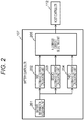
- FIG. 2 is a functional block diagram of the battery controller 107.
- the battery controller 107 includes respective functional blocks including a battery information acquiring unit 201, a first allowable current calculating unit 202, a second allowable current calculating unit 203, a third allowable current calculating unit 204, and an allowable current selecting unit 205.
- the battery controller 107 can implement these functional blocks for example by executing a predetermined program by a CPU.
- the battery information acquiring unit 201 acquires various information on the state of the battery module 101 on the basis of the respective detection results of the current sensor 102, the voltage sensor 103, and the temperature sensor 104.
- the battery information acquiring unit 201 acquires, for example, the charge/discharge current of the battery module 101 detected by the current sensor 102, the temperature of the battery module 101 detected by the temperature sensor 104, and the like as information of the battery module 101.
- the first allowable current calculating unit 202 calculates a first allowable current of the battery module 101.
- the first allowable current an allowable current of the battery module 101 in accordance with a rated value of a component through which a current flows by charging or discharging of the battery module 101. Note that a specific method of calculating the first allowable current by the first allowable current calculating unit 202 will be described later with reference to FIGS. 3 and 4 .
- the second allowable current calculating unit 203 calculates a second allowable current of the battery module 101 on the basis of the information of the battery module 101 acquired by the battery information acquiring unit 201.
- the second allowable current is an allowable current of the battery module 101 in accordance with the SOC of the battery module 101. Note that a specific method of calculating the second allowable current by the second allowable current calculating unit 203 will be described later with reference to FIGS. 5 and 6 .
- the third allowable current calculating unit 204 calculates a third allowable current of the battery module 101 on the basis of the information of the battery module 101 acquired by the battery information acquiring unit 201.
- the third allowable current is an allowable current of the battery module 101 in accordance with the SOH of the battery module 101. Note that a specific method of calculating the third allowable current by the third allowable current calculating unit 204 will be described later with reference to FIG. 7 .
- the allowable current selecting unit 205 selects one of the first allowable current, the second allowable current, and the third allowable current calculated by the first allowable current calculating unit 202, the second allowable current calculating unit 203, and the third allowable current calculating unit 204, respectively. Note that a specific method of selecting an allowable current by the allowable current selecting unit 205 will be described later. Then, a value of the selected allowable current is output to the host controller 112. When the allowable current is output from the allowable current selecting unit 205, the host controller 112 controls the battery system 100 and the inverter 110 in accordance with the value of the allowable current to perform charge/discharge control of the battery module 101.
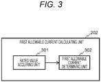
- FIG. 3 is a functional block diagram of the first allowable current calculating unit 202.
- the first allowable current calculating unit 202 includes respective functional blocks including a rated value acquiring unit 301 and a first allowable current determining unit 302.
- the rated value acquiring unit 301 acquires, as a rated value related to the first allowable current, a rated current value of each components through which a current flows by charging or discharging of the battery module 101 out of various electric components forming the battery system 100.
- the rated value acquiring unit 301 acquires a rated current value of various components such as a bus bar, a connector, a current cable, a relay (switch), a fuse, or a screw arranged on the path of charging/discharging current in the battery system 100.
- a shunt resistor, adhesive resin, or the like is arranged on a path of the charge/discharge current
- the rated value acquiring unit 301 also acquires these rated current values.
- the rated value acquiring unit 301 prestores a temperature characteristic of a rated current value of each component.
- the temperature of each component is estimated on the basis of the temperature of the battery module 101 detected by the temperature sensor 104, and then a rated current value corresponding to the temperature is acquired for each component.
- a deterioration state of each component may be estimated on the basis of a use history of the battery system 100, and a rated current value of each component may be determined in consideration of the estimation result.
- the first allowable current determining unit 302 determines the first allowable current on the basis of the rated current value of each component acquired by the rated value acquiring unit 301. For example, the first allowable current determining unit 302 determines the first allowable current in accordance with a component having the smallest rated current value.
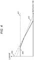
- FIG. 4 is a diagram explaining a method of determining the first allowable current by the first allowable current determining unit 302.
- each of straight lines 401, 402, and 403 represents a characteristic example of a rated current value with respect to energizing time of a component different from each other.
- the components of the battery system 100 include, in a mixed manner, a rated current value being constant irrespective of energizing time as illustrated by the straight line 401 and those whose rated current value decreases as energizing time becomes longer (as an energizing duty becomes larger) as separately illustrated by the straight lines 402 and 403.
- the first allowable current determining unit 302 can determine the first allowable current according to a characteristic of a rated current value with respect to energizing time as indicated by a polygonal line 404, for example.
- FIG. 5 is a functional block diagram of the second allowable current calculating unit 203.
- the second allowable current calculating unit 203 includes respective functional blocks including an SOC calculating unit 501, an internal resistance calculating unit 502, and a second allowable current determining unit 503.
- the SOC calculating unit 501 calculates an SOC of the battery module 101 on the basis of the detection result of a charge/discharge current by the current sensor 102 or the detection result of a voltage by the voltage sensor 103.
- the SOC calculating unit 501 can derive an SOC from an integrated value of charging or discharging currents or derive an SOC from an open circuit voltage (OCV) when the battery module 101 is not charged/discharged.
- OCV open circuit voltage
- the internal resistance calculating unit 502 calculates an internal resistance value of the battery module 101 on the basis of the SOC derived by the SOC calculating unit 501.
- the internal resistance calculating unit 502 can calculate the internal resistance value of the battery module 101 on the basis of the OCV derived from the SOC, the detection result of the charge/discharge current by the current sensor 102, and the voltage detection result at the time of charging or discharging by the voltage sensor 103.
- the internal resistance value of the battery module 101 may be derived in consideration of the temperature detected by the temperature sensor 104.
- the second allowable current determining unit 503 determines the second allowable current on the basis of the SOC derived by the SOC calculating unit 501 and the internal resistance derived by the internal resistance calculating unit 502.
- FIG. 6 is a diagram explaining a method of determining the second allowable current by the second allowable current determining unit 503.
- a curve 601 illustrates an example of an SOC-OCV curve representing the relationship between the SOC and the OCV of the battery module 101.
- Smax and Smin the maximum value and the minimum value of the SOC in which the battery module 101 is used are denoted by Smax and Smin, respectively.
- Vmax and the minimum value Vmin of the OCV of the battery module 101 are derived as points corresponding to Smax and Smin on the SOC-OCV curve 601 as illustrated in FIG. 6 .
- S(t) and V(t) values of the SOC and the OCV at desired time t
- these values can be represented by a point on the SOC-OCV curve 601, for example, a point 602.
- Ic(t) and Id(t) a charge allowable current of the battery module 101 at this time
- Ic(t) and Id(t) a discharge allowable current of the battery module 101 at this time
- R (t) represents the internal resistance of the battery module 101 at time t.
- the second allowable current determining unit 503 can determine the second allowable current by deriving the charge allowable current Ic (t) and the discharge allowable current Id (t) on the basis of the above mathematical formulas (2) and (3), respectively.
- FIG. 7 is a functional block diagram of the third allowable current calculating unit 204.
- the third allowable current calculating unit 204 includes respective functional blocks including an SOH calculating unit 701, a lifetime predicting unit 702, and a third allowable current determining unit 703.
- the SOH calculating unit 701 calculates an SOH of the battery module 101 on the basis of the detection result of a charge/discharge current by the current sensor 102 or the detection result of a voltage by the voltage sensor 103. Note that the calculation results of the SOC and the internal resistance may be acquired from the second allowable current calculating unit 203, and the SOH may be calculated on the basis of these calculation results.
- the lifetime predicting unit 702 predicts a lifetime of the battery module 101 on the basis of the SOH calculated by the SOH calculating unit 701.
- the lifetime predicting unit 702 records a history of the information of the battery module 101 acquired by the battery information acquiring unit 201 in association with the SOH of the battery module 101, for example. Estimating the future transition of the SOH on the basis of the information recorded in this manner enables calculating the deterioration progression speed of the battery module 101 and predicting the lifetime from the calculation result.
- the third allowable current determining unit 703 determines the third allowable current on the basis of the SOH derived by the SOH calculating unit 701 and the lifetime derived by the lifetime predicting unit 702.
- the third allowable current determining unit 703 compares the lifetime of the battery module 101 predicted by the lifetime predicting unit 702 with a preset target lifetime value. As a result, if a deviation between the target lifetime value and the predicted lifetime value is large, a value of the third allowable current is adjusted such that the deviation becomes smaller.
- the third allowable current calculating unit 204 can calculate the third allowable current corresponding to the SOH of the battery module 101.
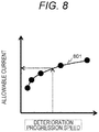
- FIG. 8 is a diagram explaining a method of determining the third allowable current by the third allowable current determining unit 703.
- a curve 801 illustrates an example of the relationship between the deterioration progression speed and the third allowable current.
- the third allowable current determining unit 703 stores data in which the relationship of FIG. 8 having been obtained in advance by a test or the like is mapped, for example. By using this data, the third allowable current determining unit 703 can determine the third allowable current in accordance with the deterioration progression speed of the battery module 101.
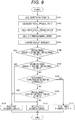
- FIG. 9 is a flowchart of charge/discharge control of the battery module 101 by the battery controller 107.
- the battery controller 107 executes charge/discharge control of the battery module 101 at every predetermined processing cycle according to the flowchart of FIG. 9 .
- step S101 the battery controller 107 acquires the various information of the battery module 101 as described above by the battery information acquiring unit 201.
- step S102 the battery controller 107 calculates the first allowable current of the battery module 101 on the basis of the information of the battery module 101 acquired in step S101 by the first allowable current calculating unit 202.
- step S103 the battery controller 107 calculates the second allowable current of the battery module 101 on the basis of the information of the battery module 101 acquired in step S101 by the second allowable current calculating unit 203.
- step S104 the battery controller 107 calculates the third allowable current of the battery module 101 on the basis of the information of the battery module 101 acquired in step S101 by the third allowable current calculating unit 204.
- step S105 the battery controller 107 compares the calculation results of steps S102 to S104 by the allowable current selecting unit 205. That is, the first allowable current calculated in step S102, the second allowable current calculated in step S103, and the third allowable current calculated in step S104 are compared to grasp the magnitude relation among them.
- step S106 the battery controller 107 determines whether the first allowable current is lower than both of the second allowable current and the third allowable current on the basis of the comparison result of step S105 by the allowable current selecting unit 205. As a result, if the determination condition is satisfied, that is, if the first allowable current is the lowest, the processing proceeds to step S109. On the other hand, if the determination condition is not satisfied, that is, if the first allowable current is higher than at least one of the second allowable current and the third allowable current, the processing proceeds to step S106.
- step S107 the battery controller 107 determines whether the second allowable current is lower than both of the first allowable current and the third allowable current on the basis of the comparison result of step S105 by the allowable current selecting unit 205. As a result, if the determination condition is satisfied, that is, if the second allowable current is the lowest, the processing proceeds to step S111. On the other hand, if the determination condition is not satisfied, that is, if the second allowable current is higher than at least one of the first allowable current and the third allowable current, the processing proceeds to step S108.
- step S108 the battery controller 107 determines whether deterioration suppression of the battery module 101 is to be prioritized in the current situation by the allowable current selecting unit 205.
- the allowable current selecting unit 205 determines that the deterioration suppression of the battery module 101 is to be prioritized in cases such as a case where a mode that gives priority to the lifetime of the battery module 101 is set in the battery system 100 or a case where the load of the battery module 101 is small such as when the vehicle is traveling.
- the allowable current selecting unit 205 determines that the deterioration suppression of the battery module 101 is not to be prioritized in cases such as a case where a mode that gives priority to the traveling performance or fuel efficiency of the vehicle is set in the battery system 100 or when the load of the battery module 101 is large such as during acceleration of the vehicle.
- a case is considered where the battery system 100 is mounted in an electric vehicle such as a hybrid car. In such a case, when the vehicle travels on an approach road to a highway or on an uphill road or overtakes, a driver may presses on the accelerator pedal deeper and request a higher output torque from the load 111 that is an electric motor.
- the allowable current selecting unit 205 can determine that the charge/discharge performance of the battery module 101 is to be prioritized and that the deterioration suppression is not to be prioritized. Note that, other than the above, the determination in step S108 can be performed using various determination conditions. As a result, if it is determined that the deterioration suppression is to be prioritized, the processing proceeds to step S112. On the other hand, if it is determined that the deterioration suppression is not to be prioritized, the processing proceeds to step S109.
- step S109 the battery controller 107 determines whether the first allowable current is lower than the second allowable current on the basis of the comparison result of step S105 by the allowable current selecting unit 205. As a result, if the first allowable current is lower than the second allowable current, the processing proceeds to step S110. On the other hand, if the first allowable current is greater than or equal to the second allowable current, the processing proceeds to step S111.
- step S110 the battery controller 107 selects the first allowable current obtained in step S102 by the allowable current selecting unit 205 and outputs the first allowable current to the host controller 112. That is, if the first allowable current is lower than the second allowable current and the third allowable current, or if the deterioration suppression is not to be prioritized and the first allowable current is lower than the second allowable current, the battery controller 107 executes step S110. As a result, the first allowable current is selected as the allowable current in the charge/discharge control of the battery module 101.
- step S111 the battery controller 107 selects the second allowable current obtained in step S103 by the allowable current selecting unit 205 and outputs the second allowable current to the host controller 112. That is, if the second allowable current is lower than the first allowable current and the third allowable current, or if the deterioration suppression is not to be prioritized and the second allowable current is lower than the first allowable current, the battery controller 107 executes step S111. As a result, the second allowable current is selected as the allowable current in the charge/discharge control of the battery module 101.
- step S112 the battery controller 107 selects the third allowable current obtained in step S104 by the allowable current selecting unit 205 and outputs the third allowable current to the host controller 112. That is, if the deterioration suppression is to be prioritized, the battery controller 107 executes step S112. As a result, the third allowable current is selected as the allowable current in the charge/discharge control of the battery module 101.
- the battery controller 107 After executing any one of steps S110 to S112, the battery controller 107 completes the processing illustrated in the flowchart of FIG. 9 .
- FIG. 10 illustrates an example of a change in an allowable current in the case of using the conventional technique.
- the first allowable current, the second allowable current, and the third allowable current described above there are a plurality of allowable currents defined from different perspectives such as safety of parts, safety of the storage battery, and a lifetime of the storage battery.
- the minimum value of these allowable currents is used as an allowable current of a battery system as in the related art, charge/discharge control cannot be performed beyond this minimum allowable current. Therefore, as illustrated in FIG.
- FIG. 11 illustrates an example of a change in an allowable current in the case of using the present invention.
- the first, the second, and the third allowable currents defined from different perspectives can be selectively used depending on the situation. Therefore, when a request for higher output is made to the battery system 100 in the case as described above, as illustrated in FIG. 11 , it is possible to use a smaller one of the first allowable current and the second allowable current as the allowable current to temporarily increase the allowable current. As a result, it is possible to make the full use of the charge/discharge performance of the battery system.
- FIG. 12 illustrates an example of a change in an allowable current when the present invention is more proactively utilized.
- the battery system 100 is mounted to an electric vehicle such as a hybrid car and has a function that allows a driver to select between a mode that gives priority to the lifetime of the battery module 101 and a mode that gives priority to the traveling performance such as fuel consumption and acceleration performance.
- the battery system 100 uses the third allowable current as the allowable current when the driver selects the lifetime prioritized mode and, when the traveling performance prioritized mode is selected, a smaller one of the first and the second allowable currents is used as the allowable current.
- an allowable current is selected in accordance with the selection of the driver.
- the battery controller 107 includes the allowable current selecting unit 205
- the function of the allowable current selecting unit 205 may be implemented in the host controller 112.
- the battery controller 107 executes the processing of steps S101 to S104 in FIG. 9 and outputs the values of the obtained first allowable current, the second allowable current, and the third allowable current to the host controller 112.
- the host controller 112 executes the processing of steps S105 to S112 on the basis of these allowable currents output from the battery controller 107 and selects one of the first allowable current, the second allowable current, and the third allowable current. Then, the charge/discharge control of the battery module 101 is performed in accordance with the selected allowable current. Also in this manner, actions and effects similar to the above can be obtained.
Abstract
Description
- The present invention relates to a storage battery control device.
- Conventionally, in-vehicle battery systems, mounted on a hybrid electric vehicle (HEV) or a plug-in hybrid electric vehicle (PHEV) and using a lithium ion secondary battery as a storage battery, are in use. In such in-vehicle battery systems, it is necessary to limit the current flowing in a storage battery within a predetermined range from the perspective of safety of components and deterioration prevention. For example,
PTL 1 discloses a technique for setting an upper limit value of the current in accordance with the degree of deterioration of a storage battery. - PTL 1: International Publication No.
2013-094057 - The magnitude of a current to be output from an in-vehicle battery system varies depending not only on the degree of deterioration of a storage battery but also on the situation. For example, depending on the traveling state or other conditions of a vehicle, it may be necessary to temporarily supply a large current to a load. In such a case, it is preferable to temporarily raise the upper limit value of the current since the influence on deterioration of the storage battery is small if it is a short time. However, in the conventional technique described in
PTL 1, the upper limit value of the current is set in accordance with the degree of deterioration of the storage battery, and thus it is difficult to appropriately control the current of the storage battery depending on the situation. - A storage battery control device according to the present invention includes: a battery information acquiring unit for acquiring information on a storage battery; a first allowable current calculating unit for calculating a first allowable current of the storage battery in accordance with a rated value of a component through which a current flows by charging or discharging of the storage battery; a second allowable current calculating unit for calculating a second allowable current of the storage battery in accordance with a charging state of the storage battery on the basis of the information acquired by the battery information acquiring unit; and a third allowable current calculating unit for calculating a third allowable current of the storage battery in accordance with a deterioration state of the storage battery on the basis of the information acquired by the battery information acquiring unit.
- According to the present invention, it is possible to appropriately control the current of a storage battery depending on the situation.
-
- [
FIG. 1] FIG. 1 is a diagram illustrating a configuration of a battery system to which a storage battery control device according to an embodiment of the present invention is applied. - [
FIG. 2] FIG. 2 is a functional block diagram of a battery controller. - [
FIG. 3] FIG. 3 is a functional block diagram of a first allowable current calculating unit. - [
FIG. 4] FIG. 4 is a diagram explaining a method of determining a first allowable current. - [
FIG. 5] FIG. 5 is a functional block diagram of a second allowable current calculating unit. - [
FIG. 6] FIG. 6 is a diagram explaining a method of determining a second allowable current. - [
FIG. 7] FIG. 7 is a functional block diagram of a third allowable current calculating unit. - [
FIG. 8] FIG. 8 is a diagram explaining a method of determining a third allowable current. - [
FIG. 9] FIG. 9 is a flowchart of charge/discharge control of a battery module. - [
FIG. 10] FIG. 10 is a diagram illustrating an example of a change in an allowable current in the case of using a conventional technique. - [
FIG. 11] FIG. 11 is a diagram illustrating an example of a change in an allowable current in the case of using the present invention. - [
FIG. 12] FIG. 12 is a diagram illustrating an example of a change in an allowable current in a case where the present invention is more proactively utilized. - An embodiment of the present invention will be described below with reference to the drawings.
-
FIG. 1 is a diagram illustrating a configuration of a battery system to which a storage battery control device according to an embodiment of the present invention is applied. Thebattery system 100 illustrated inFIG. 1 is connected to aninverter 110 and ahost controller 112. Aload 111 is connected to theinverter 110. - The
inverter 110 is a bidirectional inverter that operates under the control of thehost controller 112. Theinverter 110 converts DC power supplied from thebattery system 100 into AC power and outputs the AC power to theload 111. Theload 111 is, for example, a three-phase AC motor mounted on a vehicle and generates a driving force of the vehicle by being rotationally driving using the AC power supplied from theinverter 110. In addition, when regenerative power generation is performed by allowing theload 111 to operate as a generator using kinetic energy of the vehicle, AC power is output from theload 111. In this case, theinverter 110 converts the AC power output from theload 111 into DC power, and outputs the obtained DC power to thebattery system 100 for storage. In this manner, by operating theinverter 110 according to the control of thehost controller 112, thebattery system 100 is charged or discharged. - Note that the present invention is not limited to the configuration illustrated in
FIG. 1 as long as charging and discharging of thebattery system 100 can be appropriately controlled. For example, another charging system different from theinverter 110 may be connected to thebattery system 100, and charging of thebattery system 100 may be performed as needed using this charging system. - The
battery system 100 includes abattery module 101, acurrent sensor 102, avoltage sensor 103, atemperature sensor 104, a leakagecurrent sensor 105, arelay 106A, arelay 106B, and abattery controller 107. - The
battery module 101 is a chargeable/dischargeable storage battery formed by connecting a plurality of unit batteries in series or in series and in parallel. Note that thebattery module 101 may be divided into two or more groups, and a breaker which can be manually operated may be included between the groups. With this arrangement, it is possible to prevent occurrence of an electric shock accident or a short-circuit accident by opening the breaker at the time of work such as assembling, disassembling, inspection, etc. of thebattery system 100. - The
current sensor 102 detects a charge/discharge current flowing in thebattery module 101. Thevoltage sensor 103 detects the voltage of thebattery module 101. Thetemperature sensor 104 detects the temperature of thebattery module 101. The leakagecurrent sensor 105 detects the insulation resistance of thebattery module 101. The detection results of thecurrent sensor 102, thevoltage sensor 103, thetemperature sensor 104, and the leakagecurrent sensor 105 are separately output to thebattery controller 107. - The
relays battery module 101 and theinverter 110, and are controlled by thebattery controller 107 or thehost controller 112. Therelay 106A is connected between a positive electrode side of thebattery module 101 and theinverter 110, and therelay 106B is connected between a negative electrode side of thebattery module 101 and theinverter 110. Note that either one of therelays relay battery module 101 and theinverter 110, it is only required to turn on the precharge relay first and, after the current becomes sufficiently small, to turn on therelay - The
battery controller 107 corresponds to the storage battery control device according to an embodiment of the present invention. Thebattery controller 107 acquires the respective detection results of thecurrent sensor 102, thevoltage sensor 103, thetemperature sensor 104, and the leakagecurrent sensor 105 and controls thebattery system 100 on the basis of these detection results. For example, thebattery controller 107 calculates the state of charge (SOC) or the state of health (SOH) of thebattery module 101 on the basis of the detection result of a charge/discharge current by thecurrent sensor 102 or the detection result of a voltage by thevoltage sensor 103. Based on these calculation results, charge/discharge control of thebattery module 101 and balancing control for equalizing SOCs of the respective unit batteries of thebattery module 101 are performed. Thebattery controller 107 further determines whether thebattery module 101 is in a leakage state or in a state where it is likely to leak on the basis of the detection result of the insulation resistance by the leakagecurrent sensor 105. When determining that thebattery module 101 is in one of these states, thebattery controller 107 stops operation of thebattery system 100. Other than the above, thebattery controller 107 can execute various processing. - Note that, in the charge/discharge control of the
battery module 101, thebattery controller 107 calculates an allowable current for appropriately controlling the current flowing in thebattery module 101 depending on the situation and outputs the allowable current to thehost controller 112. Details of the charge/discharge control of thebattery module 101 by thebattery controller 107 will be described later in detail. - The
host controller 112 controls an operation state of thebattery system 100 or theinverter 110 on the basis of various information of thebattery module 101 transmitted from thebattery controller 107. - Next, details of the charge/discharge control of the
battery module 101 by thebattery controller 107 will be described.FIG. 2 is a functional block diagram of thebattery controller 107. As illustrated inFIG. 2 , thebattery controller 107 includes respective functional blocks including a batteryinformation acquiring unit 201, a first allowable current calculatingunit 202, a second allowable current calculatingunit 203, a third allowable current calculatingunit 204, and an allowable current selectingunit 205. Thebattery controller 107 can implement these functional blocks for example by executing a predetermined program by a CPU. - The battery
information acquiring unit 201 acquires various information on the state of thebattery module 101 on the basis of the respective detection results of thecurrent sensor 102, thevoltage sensor 103, and thetemperature sensor 104. The batteryinformation acquiring unit 201 acquires, for example, the charge/discharge current of thebattery module 101 detected by thecurrent sensor 102, the temperature of thebattery module 101 detected by thetemperature sensor 104, and the like as information of thebattery module 101. Moreover, it is also possible to acquire use time of thebattery module 101 measured by using a timer (not illustrated) incorporated in thebattery controller 107, a traveling distance of the vehicle on which thebattery module 101 is mounted, or other information as the information of thebattery module 101. That is, the batteryinformation acquiring unit 201 can acquire at least one piece of information from among the various information relating to the state of thebattery module 101 as described above. Note that information other than those mentioned above may be acquired as the information of thebattery module 101. - The first allowable current calculating
unit 202 calculates a first allowable current of thebattery module 101. The first allowable current an allowable current of thebattery module 101 in accordance with a rated value of a component through which a current flows by charging or discharging of thebattery module 101. Note that a specific method of calculating the first allowable current by the first allowable current calculatingunit 202 will be described later with reference toFIGS. 3 and4 . - The second allowable current calculating
unit 203 calculates a second allowable current of thebattery module 101 on the basis of the information of thebattery module 101 acquired by the batteryinformation acquiring unit 201. The second allowable current is an allowable current of thebattery module 101 in accordance with the SOC of thebattery module 101. Note that a specific method of calculating the second allowable current by the second allowable current calculatingunit 203 will be described later with reference toFIGS. 5 and6 . - The third allowable current calculating
unit 204 calculates a third allowable current of thebattery module 101 on the basis of the information of thebattery module 101 acquired by the batteryinformation acquiring unit 201. The third allowable current is an allowable current of thebattery module 101 in accordance with the SOH of thebattery module 101. Note that a specific method of calculating the third allowable current by the third allowable current calculatingunit 204 will be described later with reference toFIG. 7 . - The allowable current selecting
unit 205 selects one of the first allowable current, the second allowable current, and the third allowable current calculated by the first allowable current calculatingunit 202, the second allowable current calculatingunit 203, and the third allowable current calculatingunit 204, respectively. Note that a specific method of selecting an allowable current by the allowable current selectingunit 205 will be described later. Then, a value of the selected allowable current is output to thehost controller 112. When the allowable current is output from the allowable current selectingunit 205, thehost controller 112 controls thebattery system 100 and theinverter 110 in accordance with the value of the allowable current to perform charge/discharge control of thebattery module 101. - Next, a method of calculating the first allowable current by the first allowable current calculating
unit 202 will be described.FIG. 3 is a functional block diagram of the first allowable current calculatingunit 202. As illustrated inFIG. 3 , the first allowable current calculatingunit 202 includes respective functional blocks including a ratedvalue acquiring unit 301 and a first allowable current determiningunit 302. - The rated
value acquiring unit 301 acquires, as a rated value related to the first allowable current, a rated current value of each components through which a current flows by charging or discharging of thebattery module 101 out of various electric components forming thebattery system 100. For example, the ratedvalue acquiring unit 301 acquires a rated current value of various components such as a bus bar, a connector, a current cable, a relay (switch), a fuse, or a screw arranged on the path of charging/discharging current in thebattery system 100. Note that in a case where a shunt resistor, adhesive resin, or the like is arranged on a path of the charge/discharge current, the ratedvalue acquiring unit 301 also acquires these rated current values. For example, the ratedvalue acquiring unit 301 prestores a temperature characteristic of a rated current value of each component. The temperature of each component is estimated on the basis of the temperature of thebattery module 101 detected by thetemperature sensor 104, and then a rated current value corresponding to the temperature is acquired for each component. At this time, furthermore, a deterioration state of each component may be estimated on the basis of a use history of thebattery system 100, and a rated current value of each component may be determined in consideration of the estimation result. - The first allowable current determining
unit 302 determines the first allowable current on the basis of the rated current value of each component acquired by the ratedvalue acquiring unit 301. For example, the first allowable current determiningunit 302 determines the first allowable current in accordance with a component having the smallest rated current value. -
FIG. 4 is a diagram explaining a method of determining the first allowable current by the first allowable current determiningunit 302. InFIG. 4 , each ofstraight lines battery system 100 include, in a mixed manner, a rated current value being constant irrespective of energizing time as illustrated by thestraight line 401 and those whose rated current value decreases as energizing time becomes longer (as an energizing duty becomes larger) as separately illustrated by thestraight lines value acquiring unit 301, the first allowable current determiningunit 302 can determine the first allowable current according to a characteristic of a rated current value with respect to energizing time as indicated by apolygonal line 404, for example. - Next, a method of calculating the second allowable current by the second allowable current calculating
unit 203 will be described.FIG. 5 is a functional block diagram of the second allowable current calculatingunit 203. As illustrated inFIG. 5 , the second allowable current calculatingunit 203 includes respective functional blocks including anSOC calculating unit 501, an internalresistance calculating unit 502, and a second allowable current determiningunit 503. - The
SOC calculating unit 501 calculates an SOC of thebattery module 101 on the basis of the detection result of a charge/discharge current by thecurrent sensor 102 or the detection result of a voltage by thevoltage sensor 103. For example, theSOC calculating unit 501 can derive an SOC from an integrated value of charging or discharging currents or derive an SOC from an open circuit voltage (OCV) when thebattery module 101 is not charged/discharged. - The internal
resistance calculating unit 502 calculates an internal resistance value of thebattery module 101 on the basis of the SOC derived by theSOC calculating unit 501. The internalresistance calculating unit 502 can calculate the internal resistance value of thebattery module 101 on the basis of the OCV derived from the SOC, the detection result of the charge/discharge current by thecurrent sensor 102, and the voltage detection result at the time of charging or discharging by thevoltage sensor 103. At this time, the internal resistance value of thebattery module 101 may be derived in consideration of the temperature detected by thetemperature sensor 104. - The second allowable current determining
unit 503 determines the second allowable current on the basis of the SOC derived by theSOC calculating unit 501 and the internal resistance derived by the internalresistance calculating unit 502. -
FIG. 6 is a diagram explaining a method of determining the second allowable current by the second allowable current determiningunit 503. InFIG. 6 , a curve 601 illustrates an example of an SOC-OCV curve representing the relationship between the SOC and the OCV of thebattery module 101. When the maximum value and the minimum value of the SOC in which thebattery module 101 is used are denoted by Smax and Smin, respectively, the maximum value Vmax and the minimum value Vmin of the OCV of thebattery module 101 are derived as points corresponding to Smax and Smin on the SOC-OCV curve 601 as illustrated inFIG. 6 . - Here, when values of the SOC and the OCV at desired time t are represented as S(t) and V(t), respectively, these values can be represented by a point on the SOC-OCV curve 601, for example, a point 602. When a charge allowable current and a discharge allowable current of the
battery module 101 at this time are denoted by Ic(t) and Id(t), respectively, a relationship as illustrated inFIG. 6 holds between the point 602 and these currents. InFIG. 6 , R (t) represents the internal resistance of thebattery module 101 at time t. - The above relationship is represented by the following mathematical formula (1).

- From the mathematical formula (1), the following mathematical formulas (2) and (3) are derived as equations for deriving a charge allowable current Ic (t) and a discharge allowable current Id (t).


- The second allowable current determining
unit 503 can determine the second allowable current by deriving the charge allowable current Ic (t) and the discharge allowable current Id (t) on the basis of the above mathematical formulas (2) and (3), respectively. - Next, a method of calculating the third allowable current by the third allowable current calculating
unit 204 will be described.FIG. 7 is a functional block diagram of the third allowable current calculatingunit 204. As illustrated inFIG. 7 , the third allowable current calculatingunit 204 includes respective functional blocks including anSOH calculating unit 701, alifetime predicting unit 702, and a third allowable current determiningunit 703. - The
SOH calculating unit 701 calculates an SOH of thebattery module 101 on the basis of the detection result of a charge/discharge current by thecurrent sensor 102 or the detection result of a voltage by thevoltage sensor 103. Note that the calculation results of the SOC and the internal resistance may be acquired from the second allowable current calculatingunit 203, and the SOH may be calculated on the basis of these calculation results. - The
lifetime predicting unit 702 predicts a lifetime of thebattery module 101 on the basis of the SOH calculated by theSOH calculating unit 701. Thelifetime predicting unit 702 records a history of the information of thebattery module 101 acquired by the batteryinformation acquiring unit 201 in association with the SOH of thebattery module 101, for example. Estimating the future transition of the SOH on the basis of the information recorded in this manner enables calculating the deterioration progression speed of thebattery module 101 and predicting the lifetime from the calculation result. - The third allowable current determining
unit 703 determines the third allowable current on the basis of the SOH derived by theSOH calculating unit 701 and the lifetime derived by thelifetime predicting unit 702. The third allowable current determiningunit 703 compares the lifetime of thebattery module 101 predicted by thelifetime predicting unit 702 with a preset target lifetime value. As a result, if a deviation between the target lifetime value and the predicted lifetime value is large, a value of the third allowable current is adjusted such that the deviation becomes smaller. As a result, the third allowable current calculatingunit 204 can calculate the third allowable current corresponding to the SOH of thebattery module 101. -
FIG. 8 is a diagram explaining a method of determining the third allowable current by the third allowable current determiningunit 703. InFIG. 8 , acurve 801 illustrates an example of the relationship between the deterioration progression speed and the third allowable current. The third allowable current determiningunit 703 stores data in which the relationship ofFIG. 8 having been obtained in advance by a test or the like is mapped, for example. By using this data, the third allowable current determiningunit 703 can determine the third allowable current in accordance with the deterioration progression speed of thebattery module 101. -
FIG. 9 is a flowchart of charge/discharge control of thebattery module 101 by thebattery controller 107. Thebattery controller 107 executes charge/discharge control of thebattery module 101 at every predetermined processing cycle according to the flowchart ofFIG. 9 . - In step S101, the
battery controller 107 acquires the various information of thebattery module 101 as described above by the batteryinformation acquiring unit 201. - In step S102, the
battery controller 107 calculates the first allowable current of thebattery module 101 on the basis of the information of thebattery module 101 acquired in step S101 by the first allowable current calculatingunit 202. - In step S103, the
battery controller 107 calculates the second allowable current of thebattery module 101 on the basis of the information of thebattery module 101 acquired in step S101 by the second allowable current calculatingunit 203. - In step S104, the
battery controller 107 calculates the third allowable current of thebattery module 101 on the basis of the information of thebattery module 101 acquired in step S101 by the third allowable current calculatingunit 204. - In step S105, the
battery controller 107 compares the calculation results of steps S102 to S104 by the allowable current selectingunit 205. That is, the first allowable current calculated in step S102, the second allowable current calculated in step S103, and the third allowable current calculated in step S104 are compared to grasp the magnitude relation among them. - In step S106, the
battery controller 107 determines whether the first allowable current is lower than both of the second allowable current and the third allowable current on the basis of the comparison result of step S105 by the allowable current selectingunit 205. As a result, if the determination condition is satisfied, that is, if the first allowable current is the lowest, the processing proceeds to step S109. On the other hand, if the determination condition is not satisfied, that is, if the first allowable current is higher than at least one of the second allowable current and the third allowable current, the processing proceeds to step S106. - In step S107, the
battery controller 107 determines whether the second allowable current is lower than both of the first allowable current and the third allowable current on the basis of the comparison result of step S105 by the allowable current selectingunit 205. As a result, if the determination condition is satisfied, that is, if the second allowable current is the lowest, the processing proceeds to step S111. On the other hand, if the determination condition is not satisfied, that is, if the second allowable current is higher than at least one of the first allowable current and the third allowable current, the processing proceeds to step S108. - In step S108, the
battery controller 107 determines whether deterioration suppression of thebattery module 101 is to be prioritized in the current situation by the allowable current selectingunit 205. The allowable current selectingunit 205 determines that the deterioration suppression of thebattery module 101 is to be prioritized in cases such as a case where a mode that gives priority to the lifetime of thebattery module 101 is set in thebattery system 100 or a case where the load of thebattery module 101 is small such as when the vehicle is traveling. On the other hand, the allowable current selectingunit 205 determines that the deterioration suppression of thebattery module 101 is not to be prioritized in cases such as a case where a mode that gives priority to the traveling performance or fuel efficiency of the vehicle is set in thebattery system 100 or when the load of thebattery module 101 is large such as during acceleration of the vehicle. As a specific example, a case is considered where thebattery system 100 is mounted in an electric vehicle such as a hybrid car. In such a case, when the vehicle travels on an approach road to a highway or on an uphill road or overtakes, a driver may presses on the accelerator pedal deeper and request a higher output torque from theload 111 that is an electric motor. If the allowable current selectingunit 205 has determined whether the request for a higher output has been made and determined that the request for a higher output has been made on the basis of an amount of change in the degree of accelerator opening, the allowable current selectingunit 205 can determine that the charge/discharge performance of thebattery module 101 is to be prioritized and that the deterioration suppression is not to be prioritized. Note that, other than the above, the determination in step S108 can be performed using various determination conditions. As a result, if it is determined that the deterioration suppression is to be prioritized, the processing proceeds to step S112. On the other hand, if it is determined that the deterioration suppression is not to be prioritized, the processing proceeds to step S109. - In step S109, the
battery controller 107 determines whether the first allowable current is lower than the second allowable current on the basis of the comparison result of step S105 by the allowable current selectingunit 205. As a result, if the first allowable current is lower than the second allowable current, the processing proceeds to step S110. On the other hand, if the first allowable current is greater than or equal to the second allowable current, the processing proceeds to step S111. - In step S110, the
battery controller 107 selects the first allowable current obtained in step S102 by the allowable current selectingunit 205 and outputs the first allowable current to thehost controller 112. That is, if the first allowable current is lower than the second allowable current and the third allowable current, or if the deterioration suppression is not to be prioritized and the first allowable current is lower than the second allowable current, thebattery controller 107 executes step S110. As a result, the first allowable current is selected as the allowable current in the charge/discharge control of thebattery module 101. - In step S111, the
battery controller 107 selects the second allowable current obtained in step S103 by the allowable current selectingunit 205 and outputs the second allowable current to thehost controller 112. That is, if the second allowable current is lower than the first allowable current and the third allowable current, or if the deterioration suppression is not to be prioritized and the second allowable current is lower than the first allowable current, thebattery controller 107 executes step S111. As a result, the second allowable current is selected as the allowable current in the charge/discharge control of thebattery module 101. - In step S112, the
battery controller 107 selects the third allowable current obtained in step S104 by the allowable current selectingunit 205 and outputs the third allowable current to thehost controller 112. That is, if the deterioration suppression is to be prioritized, thebattery controller 107 executes step S112. As a result, the third allowable current is selected as the allowable current in the charge/discharge control of thebattery module 101. - After executing any one of steps S110 to S112, the
battery controller 107 completes the processing illustrated in the flowchart ofFIG. 9 . - Hereinafter, effects of the present invention will be described with reference to
FIGS. 10 ,11 , and12 .FIG. 10 illustrates an example of a change in an allowable current in the case of using the conventional technique. Generally in a battery system using a storage battery, as in the case of the first allowable current, the second allowable current, and the third allowable current described above, there are a plurality of allowable currents defined from different perspectives such as safety of parts, safety of the storage battery, and a lifetime of the storage battery. However, in a case where the minimum value of these allowable currents is used as an allowable current of a battery system as in the related art, charge/discharge control cannot be performed beyond this minimum allowable current. Therefore, as illustrated inFIG. 10 , in such a case where the magnitude relationship of allowable currents differs between low temperature and normal temperature and the third allowable current is lower than the first and the second allowable currents at normal temperature, charge/discharge control is always performed according to the minimum allowable current although there is no problem even if the charge/discharge current temporarily exceeds the third allowable current. As a result, it is not possible to perform charging or discharging utilizing a range originally available at a room temperature, and the performance of the battery system cannot be exerted at the maximum when necessary. - On the other hand,
FIG. 11 illustrates an example of a change in an allowable current in the case of using the present invention. In the present invention, as described in the above embodiment, the first, the second, and the third allowable currents defined from different perspectives can be selectively used depending on the situation. Therefore, when a request for higher output is made to thebattery system 100 in the case as described above, as illustrated inFIG. 11 , it is possible to use a smaller one of the first allowable current and the second allowable current as the allowable current to temporarily increase the allowable current. As a result, it is possible to make the full use of the charge/discharge performance of the battery system. -
FIG. 12 illustrates an example of a change in an allowable current when the present invention is more proactively utilized. For example, it is assumed that thebattery system 100 is mounted to an electric vehicle such as a hybrid car and has a function that allows a driver to select between a mode that gives priority to the lifetime of thebattery module 101 and a mode that gives priority to the traveling performance such as fuel consumption and acceleration performance. In such a case, as illustrated inFIG. 12 , thebattery system 100 uses the third allowable current as the allowable current when the driver selects the lifetime prioritized mode and, when the traveling performance prioritized mode is selected, a smaller one of the first and the second allowable currents is used as the allowable current. In this manner, it is also possible to employ a system in which an allowable current is selected in accordance with the selection of the driver. - According to the embodiment of the present invention described above, the following operational effects are obtained.
- (1) The
battery controller 107 includes the batteryinformation acquiring unit 201, the first allowable current calculatingunit 202, the second allowable current calculatingunit 203, and the third allowable current calculatingunit 204. The batteryinformation acquiring unit 201 acquires information on thebattery module 101 which is a storage battery (step S101) . The first allowable current calculatingunit 202 calculates the first allowable current of thebattery module 101 in accordance with a rated value of a component through which a current flows by charging or discharging of the battery module 101 (step S102) . The second allowable current calculatingunit 203 calculates the second allowable current of thebattery module 101 in accordance with an SOC of thebattery module 101 on the basis of the information acquired by the battery information acquiring unit 201 (step S103). The third allowable current calculatingunit 204 calculates the third allowable current of thebattery module 101 in accordance with an SOH of thebattery module 101 on the basis of the information acquired by the battery information acquiring unit 201 (step S104). In this manner, it is possible to appropriately control the current of thebattery module 101 depending on the situation on the basis of the calculation results of these allowable currents. - (2) The
battery controller 107 further includes the allowable current selectingunit 205 for selecting and outputting any one of the first allowable current, the second allowable current, and the third allowable current. In this manner, it is possible to select an appropriate allowable current depending on the situation and to use the allowable current in the charge/discharge control of thebattery module 101. - (3) In a case where the first allowable current is lower than the second allowable current and the third allowable current (step S106), the allowable current selecting
unit 205 selects the first allowable current (step S110), and the allowable current selectingunit 205 selects the second allowable current in a case where the second allowable current is lower than the first allowable current and the third allowable current (step Sill) . In this manner, in a case where any one of the first allowable current and the second allowable current is the lowest, the charge/discharge control of thebattery module 101 can be performed in accordance with the lowest allowable current. Therefore, it is possible to prevent failure of thebattery system 100 and to maintain the performance of thebattery module 101. - (4) The allowable current selecting
unit 205 determines whether deterioration suppression of thebattery module 101 is to be prioritized (step S108) . As a result, if it is determined that the deterioration suppression of thebattery module 101 is to be prioritized, the third allowable current is selected (step S112). If it is determined that the deterioration suppression of thebattery module 101 is not to be prioritized, the first allowable current or the second allowable current is selected (steps S110 and S111). In this manner, when the deterioration suppression of thebattery module 101 is to be prioritized, the charge/discharge control of thebattery module 101 can be performed in accordance with the third allowable current. Therefore, deterioration of thebattery module 101 can be suppressed, and the lifetime can be secured. - Note that In the embodiment described above, the example in which the
battery controller 107 includes the allowable current selectingunit 205 has been described; however, the function of the allowable current selectingunit 205 may be implemented in thehost controller 112. In this case, thebattery controller 107 executes the processing of steps S101 to S104 inFIG. 9 and outputs the values of the obtained first allowable current, the second allowable current, and the third allowable current to thehost controller 112. Thehost controller 112 executes the processing of steps S105 to S112 on the basis of these allowable currents output from thebattery controller 107 and selects one of the first allowable current, the second allowable current, and the third allowable current. Then, the charge/discharge control of thebattery module 101 is performed in accordance with the selected allowable current. Also in this manner, actions and effects similar to the above can be obtained. - The present invention is not limited to the above embodiment. Other aspects conceivable within the range of technical ideas of the present invention are also included within the scope of the present invention.
-
- 100:
- battery system
- 101:
- battery module
- 102:
- current sensor
- 103:
- voltage sensor
- 104:
- temperature sensor
- 105:
- leakage current sensor
- 106A, 106B:
- relay
- 107:
- battery controller
- 110:
- inverter
- 111:
- load
- 112:
- host controller
- 201:
- battery information acquiring unit
- 202:
- first allowable current calculating unit
- 203:
- second allowable current calculating unit
- 204:
- third allowable current calculating unit
- 205:
- allowable current selecting unit
Claims (4)
- A storage battery control device, comprising:a battery information acquiring unit for acquiring information on a storage battery;a first allowable current calculating unit for calculating a first allowable current of the storage battery in accordance with a rated value of a component through which a current flows by charging or discharging of the storage battery;a second allowable current calculating unit for calculating a second allowable current of the storage battery in accordance with a charging state of the storage battery on the basis of the information acquired by the battery information acquiring unit; anda third allowable current calculating unit for calculating a third allowable current of the storage battery in accordance with a deterioration state of the storage battery on the basis of the information acquired by the battery information acquiring unit.
- The storage battery control device according to claim 1, further comprising:
an allowable current selecting unit for selecting and outputting one of the first allowable current, the second allowable current, and the third allowable current. - The storage battery control device according to claim 2,
wherein the allowable current selecting unit selects the first allowable current in a case where the first allowable current is lower than the second allowable current and the third allowable current, and
the allowable current selecting unit selects the second allowable current in a case where the second allowable current is lower than the first allowable current and the third allowable current. - The storage battery control device according to claim 2 or 3,
wherein the allowable current selecting unit determines whether deterioration suppression of the storage battery is to be prioritized,
the allowable current selecting unit selects the third allowable current when determining that the deterioration suppression of the storage battery is to be prioritized, and
the allowable current selecting unit selects the first allowable current or the second allowable current when determining that the deterioration suppression of the storage battery is not to be prioritized.
Applications Claiming Priority (2)
| Application Number | Priority Date | Filing Date | Title |
|---|---|---|---|
| JP2015177561A JP2017055551A (en) | 2015-09-09 | 2015-09-09 | Power storage battery control device |
| PCT/JP2016/073215 WO2017043236A1 (en) | 2015-09-09 | 2016-08-08 | Storage battery control device |
Publications (3)
| Publication Number | Publication Date |
|---|---|
| EP3349320A1 true EP3349320A1 (en) | 2018-07-18 |
| EP3349320A4 EP3349320A4 (en) | 2019-05-08 |
| EP3349320B1 EP3349320B1 (en) | 2022-01-05 |
Family
ID=58239392
Family Applications (1)
| Application Number | Title | Priority Date | Filing Date |
|---|---|---|---|
| EP16844100.4A Active EP3349320B1 (en) | 2015-09-09 | 2016-08-08 | Storage battery control device |
Country Status (5)
| Country | Link |
|---|---|
| US (2) | US10879570B2 (en) |
| EP (1) | EP3349320B1 (en) |
| JP (2) | JP2017055551A (en) |
| CN (1) | CN107852010B (en) |
| WO (1) | WO2017043236A1 (en) |
Families Citing this family (8)
| Publication number | Priority date | Publication date | Assignee | Title |
|---|---|---|---|---|
| JP7067909B2 (en) * | 2017-12-04 | 2022-05-16 | トヨタ自動車株式会社 | Rechargeable battery system |
| WO2020017079A1 (en) * | 2018-07-17 | 2020-01-23 | パナソニックIpマネジメント株式会社 | Power source system and management method |
| WO2021059950A1 (en) * | 2019-09-25 | 2021-04-01 | パナソニックIpマネジメント株式会社 | In-vehicle notification device, notification program, and calculation device |
| US11454673B2 (en) * | 2020-02-12 | 2022-09-27 | Karma Automotive Llc | Battery current limits estimation based on RC model |
| JP7414637B2 (en) * | 2020-05-19 | 2024-01-16 | 本田技研工業株式会社 | Control device, control system, control method, and program |
| CN114516284A (en) * | 2020-11-18 | 2022-05-20 | 苏州泰亚车辆技术有限公司 | Automobile battery detection method, detection system, electric automobile and server |
| WO2023070323A1 (en) * | 2021-10-26 | 2023-05-04 | 东莞新能安科技有限公司 | Electrochemical apparatus management method, system, electrochemical apparatus and electronic device |
| CN115593273B (en) * | 2022-12-12 | 2023-04-07 | 成都壹为新能源汽车有限公司 | Electric automobile chassis system and control method |
Family Cites Families (13)
| Publication number | Priority date | Publication date | Assignee | Title |
|---|---|---|---|---|
| JP2001157310A (en) | 1999-11-25 | 2001-06-08 | Sanyo Electric Co Ltd | Method for controlling battery of electric vehicle and battery control device |
| JP4341704B2 (en) | 2007-07-12 | 2009-10-07 | トヨタ自動車株式会社 | Hybrid vehicle and control method of hybrid vehicle |
| JP2009207312A (en) | 2008-02-28 | 2009-09-10 | Sanyo Electric Co Ltd | Vehicular power supply unit and current controlling method therefor |
| JP5454789B2 (en) * | 2010-04-27 | 2014-03-26 | 三菱自動車工業株式会社 | Control device for electric vehicle |
| US8359132B2 (en) * | 2010-06-16 | 2013-01-22 | Toyota Motor Engineering & Manufacturing North America, Inc. | System and method for optimizing use of a battery |
| WO2012098794A1 (en) * | 2011-01-18 | 2012-07-26 | 日産自動車株式会社 | Battery control device |
| JP5819443B2 (en) * | 2011-12-22 | 2015-11-24 | 日立オートモティブシステムズ株式会社 | Battery control device, battery system |
| KR20130098611A (en) * | 2012-02-28 | 2013-09-05 | 삼성에스디아이 주식회사 | Charging device for battery and method of the same |
| WO2014027389A1 (en) * | 2012-08-13 | 2014-02-20 | 日立ビークルエナジー株式会社 | Cell control device and secondary cell system |
| US9209494B2 (en) * | 2012-09-28 | 2015-12-08 | Palo Alto Research Center Incorporated | Monitoring/managing electrochemical energy device using detected intercalation stage changes |
| JP5824501B2 (en) * | 2013-12-06 | 2015-11-25 | 本田技研工業株式会社 | Control device for hybrid vehicle |
| JP5888315B2 (en) * | 2013-12-18 | 2016-03-22 | トヨタ自動車株式会社 | Power storage system |
| JP6316690B2 (en) * | 2014-07-17 | 2018-04-25 | 日立オートモティブシステムズ株式会社 | Battery state detection device, secondary battery system, battery state detection program, battery state detection method |
-
2015
- 2015-09-09 JP JP2015177561A patent/JP2017055551A/en active Pending
-
2016
- 2016-08-08 CN CN201680044225.4A patent/CN107852010B/en active Active
- 2016-08-08 US US15/741,784 patent/US10879570B2/en active Active
- 2016-08-08 WO PCT/JP2016/073215 patent/WO2017043236A1/en active Application Filing
- 2016-08-08 EP EP16844100.4A patent/EP3349320B1/en active Active
-
2020
- 2020-12-01 JP JP2020199661A patent/JP7100104B2/en active Active
- 2020-12-28 US US17/134,736 patent/US11532841B2/en active Active
Also Published As
| Publication number | Publication date |
|---|---|
| EP3349320B1 (en) | 2022-01-05 |
| JP2021061747A (en) | 2021-04-15 |
| US20210119272A1 (en) | 2021-04-22 |
| US20180198175A1 (en) | 2018-07-12 |
| CN107852010B (en) | 2021-01-08 |
| CN107852010A (en) | 2018-03-27 |
| JP7100104B2 (en) | 2022-07-12 |
| EP3349320A4 (en) | 2019-05-08 |
| WO2017043236A1 (en) | 2017-03-16 |
| US10879570B2 (en) | 2020-12-29 |
| US11532841B2 (en) | 2022-12-20 |
| JP2017055551A (en) | 2017-03-16 |
Similar Documents
| Publication | Publication Date | Title |
|---|---|---|
| US11532841B2 (en) | Storage battery control device | |
| US10553896B2 (en) | Battery capacity degradation resolution methods and systems | |
| US9880224B2 (en) | Battery system monitoring device | |
| EP1914559B1 (en) | Battery management system (BMS) and driving method thereof | |
| US20140176085A1 (en) | Battery controller of vehicle | |
| EP3352289A1 (en) | Storage battery control device | |
| EP2509186B1 (en) | Power supply apparatus and method of controlling the same | |
| US20160096433A1 (en) | Bus leakage resistance estimation for electrical isolation testing and diagnostics | |
| EP2670018B1 (en) | Electric vehicle battery system | |
| US10389143B2 (en) | Battery power prediction for high load events | |
| CN111746279B (en) | Power supply system | |
| CN115038611A (en) | Battery power limit estimation based on RC model | |
| US9365129B2 (en) | Vehicle having an electric motor and method of controlling a display displaying a cruising distance of the vehicle | |
| JP6827355B2 (en) | Battery control device | |
| JP5978143B2 (en) | Battery system | |
| EP3770002B1 (en) | Method for capacitor precharging and capacitance measurement in electric vehicle drive system | |
| JP5978144B2 (en) | Battery system | |
| CN113752840A (en) | Battery system | |
| EP3872920A1 (en) | Battery control device | |
| CN111746278A (en) | Battery controller and battery control method | |
| KR101481281B1 (en) | System and method for detecting disconnection of converter input link and power module having the same |
Legal Events
| Date | Code | Title | Description |
|---|---|---|---|
| STAA | Information on the status of an ep patent application or granted ep patent |
Free format text: STATUS: THE INTERNATIONAL PUBLICATION HAS BEEN MADE |
|
| PUAI | Public reference made under article 153(3) epc to a published international application that has entered the european phase |
Free format text: ORIGINAL CODE: 0009012 |
|
| STAA | Information on the status of an ep patent application or granted ep patent |
Free format text: STATUS: REQUEST FOR EXAMINATION WAS MADE |
|
| 17P | Request for examination filed |
Effective date: 20180323 |
|
| AK | Designated contracting states |
Kind code of ref document: A1 Designated state(s): AL AT BE BG CH CY CZ DE DK EE ES FI FR GB GR HR HU IE IS IT LI LT LU LV MC MK MT NL NO PL PT RO RS SE SI SK SM TR |
|
| AX | Request for extension of the european patent |
Extension state: BA ME |
|
| DAV | Request for validation of the european patent (deleted) | ||
| DAX | Request for extension of the european patent (deleted) | ||
| A4 | Supplementary search report drawn up and despatched |
Effective date: 20190404 |
|
| RIC1 | Information provided on ipc code assigned before grant |
Ipc: H01M 10/44 20060101ALI20190329BHEP Ipc: G01R 31/36 20190101ALI20190329BHEP Ipc: H02J 7/00 20060101AFI20190329BHEP Ipc: B60L 3/00 20190101ALI20190329BHEP Ipc: H01M 10/48 20060101ALI20190329BHEP Ipc: H01M 10/42 20060101ALI20190329BHEP |
|
| RAP1 | Party data changed (applicant data changed or rights of an application transferred) |
Owner name: VEHICLE ENERGY JAPAN INC. |
|
| REG | Reference to a national code |
Ref country code: DE Ref legal event code: R079 Ref document number: 602016068149 Country of ref document: DE Free format text: PREVIOUS MAIN CLASS: H02J0007000000 Ipc: H01M0010440000 |
|
| GRAP | Despatch of communication of intention to grant a patent |
Free format text: ORIGINAL CODE: EPIDOSNIGR1 |
|
| STAA | Information on the status of an ep patent application or granted ep patent |
Free format text: STATUS: GRANT OF PATENT IS INTENDED |
|
| RIC1 | Information provided on ipc code assigned before grant |
Ipc: H01M 10/44 20060101AFI20210617BHEP Ipc: B60L 3/00 20190101ALI20210617BHEP Ipc: G01R 31/36 20200101ALI20210617BHEP Ipc: H01M 10/42 20060101ALI20210617BHEP Ipc: B60L 58/10 20190101ALI20210617BHEP Ipc: G01R 31/367 20190101ALI20210617BHEP Ipc: H01M 10/48 20060101ALN20210617BHEP Ipc: G01R 31/364 20190101ALN20210617BHEP Ipc: G01R 31/392 20190101ALN20210617BHEP |
|
| INTG | Intention to grant announced |
Effective date: 20210715 |
|
| GRAS | Grant fee paid |
Free format text: ORIGINAL CODE: EPIDOSNIGR3 |
|
| GRAA | (expected) grant |
Free format text: ORIGINAL CODE: 0009210 |
|
| STAA | Information on the status of an ep patent application or granted ep patent |
Free format text: STATUS: THE PATENT HAS BEEN GRANTED |
|
| AK | Designated contracting states |
Kind code of ref document: B1 Designated state(s): AL AT BE BG CH CY CZ DE DK EE ES FI FR GB GR HR HU IE IS IT LI LT LU LV MC MK MT NL NO PL PT RO RS SE SI SK SM TR |
|
| REG | Reference to a national code |
Ref country code: GB Ref legal event code: FG4D |
|
| RIN1 | Information on inventor provided before grant (corrected) |
Inventor name: NAKAO, RYOHHEI Inventor name: OHKAWA, KEIICHIRO Inventor name: YAMAZOE, TAKANORI Inventor name: YONEMOTO, MASAHIRO Inventor name: SAKABE, KEI Inventor name: YAMAUCHI, SHIN |
|
| REG | Reference to a national code |
Ref country code: CH Ref legal event code: EP |
|
| REG | Reference to a national code |
Ref country code: AT Ref legal event code: REF Ref document number: 1461386 Country of ref document: AT Kind code of ref document: T Effective date: 20220115 |
|
| REG | Reference to a national code |
Ref country code: DE Ref legal event code: R096 Ref document number: 602016068149 Country of ref document: DE |
|
| REG | Reference to a national code |
Ref country code: IE Ref legal event code: FG4D |
|
| REG | Reference to a national code |
Ref country code: LT Ref legal event code: MG9D |
|
| REG | Reference to a national code |
Ref country code: NL Ref legal event code: MP Effective date: 20220105 |
|
| REG | Reference to a national code |
Ref country code: AT Ref legal event code: MK05 Ref document number: 1461386 Country of ref document: AT Kind code of ref document: T Effective date: 20220105 |
|
| PG25 | Lapsed in a contracting state [announced via postgrant information from national office to epo] |
Ref country code: NL Free format text: LAPSE BECAUSE OF FAILURE TO SUBMIT A TRANSLATION OF THE DESCRIPTION OR TO PAY THE FEE WITHIN THE PRESCRIBED TIME-LIMIT Effective date: 20220105 |
|
| PG25 | Lapsed in a contracting state [announced via postgrant information from national office to epo] |
Ref country code: SE Free format text: LAPSE BECAUSE OF FAILURE TO SUBMIT A TRANSLATION OF THE DESCRIPTION OR TO PAY THE FEE WITHIN THE PRESCRIBED TIME-LIMIT Effective date: 20220105 Ref country code: RS Free format text: LAPSE BECAUSE OF FAILURE TO SUBMIT A TRANSLATION OF THE DESCRIPTION OR TO PAY THE FEE WITHIN THE PRESCRIBED TIME-LIMIT Effective date: 20220105 Ref country code: PT Free format text: LAPSE BECAUSE OF FAILURE TO SUBMIT A TRANSLATION OF THE DESCRIPTION OR TO PAY THE FEE WITHIN THE PRESCRIBED TIME-LIMIT Effective date: 20220505 Ref country code: NO Free format text: LAPSE BECAUSE OF FAILURE TO SUBMIT A TRANSLATION OF THE DESCRIPTION OR TO PAY THE FEE WITHIN THE PRESCRIBED TIME-LIMIT Effective date: 20220405 Ref country code: LT Free format text: LAPSE BECAUSE OF FAILURE TO SUBMIT A TRANSLATION OF THE DESCRIPTION OR TO PAY THE FEE WITHIN THE PRESCRIBED TIME-LIMIT Effective date: 20220105 Ref country code: HR Free format text: LAPSE BECAUSE OF FAILURE TO SUBMIT A TRANSLATION OF THE DESCRIPTION OR TO PAY THE FEE WITHIN THE PRESCRIBED TIME-LIMIT Effective date: 20220105 Ref country code: ES Free format text: LAPSE BECAUSE OF FAILURE TO SUBMIT A TRANSLATION OF THE DESCRIPTION OR TO PAY THE FEE WITHIN THE PRESCRIBED TIME-LIMIT Effective date: 20220105 Ref country code: BG Free format text: LAPSE BECAUSE OF FAILURE TO SUBMIT A TRANSLATION OF THE DESCRIPTION OR TO PAY THE FEE WITHIN THE PRESCRIBED TIME-LIMIT Effective date: 20220405 |
|
| PG25 | Lapsed in a contracting state [announced via postgrant information from national office to epo] |
Ref country code: PL Free format text: LAPSE BECAUSE OF FAILURE TO SUBMIT A TRANSLATION OF THE DESCRIPTION OR TO PAY THE FEE WITHIN THE PRESCRIBED TIME-LIMIT Effective date: 20220105 Ref country code: LV Free format text: LAPSE BECAUSE OF FAILURE TO SUBMIT A TRANSLATION OF THE DESCRIPTION OR TO PAY THE FEE WITHIN THE PRESCRIBED TIME-LIMIT Effective date: 20220105 Ref country code: GR Free format text: LAPSE BECAUSE OF FAILURE TO SUBMIT A TRANSLATION OF THE DESCRIPTION OR TO PAY THE FEE WITHIN THE PRESCRIBED TIME-LIMIT Effective date: 20220406 Ref country code: FI Free format text: LAPSE BECAUSE OF FAILURE TO SUBMIT A TRANSLATION OF THE DESCRIPTION OR TO PAY THE FEE WITHIN THE PRESCRIBED TIME-LIMIT Effective date: 20220105 Ref country code: AT Free format text: LAPSE BECAUSE OF FAILURE TO SUBMIT A TRANSLATION OF THE DESCRIPTION OR TO PAY THE FEE WITHIN THE PRESCRIBED TIME-LIMIT Effective date: 20220105 |
|
| PG25 | Lapsed in a contracting state [announced via postgrant information from national office to epo] |
Ref country code: IS Free format text: LAPSE BECAUSE OF FAILURE TO SUBMIT A TRANSLATION OF THE DESCRIPTION OR TO PAY THE FEE WITHIN THE PRESCRIBED TIME-LIMIT Effective date: 20220505 |
|
| REG | Reference to a national code |
Ref country code: DE Ref legal event code: R097 Ref document number: 602016068149 Country of ref document: DE |
|
| PG25 | Lapsed in a contracting state [announced via postgrant information from national office to epo] |
Ref country code: SM Free format text: LAPSE BECAUSE OF FAILURE TO SUBMIT A TRANSLATION OF THE DESCRIPTION OR TO PAY THE FEE WITHIN THE PRESCRIBED TIME-LIMIT Effective date: 20220105 Ref country code: SK Free format text: LAPSE BECAUSE OF FAILURE TO SUBMIT A TRANSLATION OF THE DESCRIPTION OR TO PAY THE FEE WITHIN THE PRESCRIBED TIME-LIMIT Effective date: 20220105 Ref country code: RO Free format text: LAPSE BECAUSE OF FAILURE TO SUBMIT A TRANSLATION OF THE DESCRIPTION OR TO PAY THE FEE WITHIN THE PRESCRIBED TIME-LIMIT Effective date: 20220105 Ref country code: EE Free format text: LAPSE BECAUSE OF FAILURE TO SUBMIT A TRANSLATION OF THE DESCRIPTION OR TO PAY THE FEE WITHIN THE PRESCRIBED TIME-LIMIT Effective date: 20220105 Ref country code: DK Free format text: LAPSE BECAUSE OF FAILURE TO SUBMIT A TRANSLATION OF THE DESCRIPTION OR TO PAY THE FEE WITHIN THE PRESCRIBED TIME-LIMIT Effective date: 20220105 Ref country code: CZ Free format text: LAPSE BECAUSE OF FAILURE TO SUBMIT A TRANSLATION OF THE DESCRIPTION OR TO PAY THE FEE WITHIN THE PRESCRIBED TIME-LIMIT Effective date: 20220105 |
|
| PLBE | No opposition filed within time limit |
Free format text: ORIGINAL CODE: 0009261 |
|
| STAA | Information on the status of an ep patent application or granted ep patent |
Free format text: STATUS: NO OPPOSITION FILED WITHIN TIME LIMIT |
|
| PG25 | Lapsed in a contracting state [announced via postgrant information from national office to epo] |
Ref country code: AL Free format text: LAPSE BECAUSE OF FAILURE TO SUBMIT A TRANSLATION OF THE DESCRIPTION OR TO PAY THE FEE WITHIN THE PRESCRIBED TIME-LIMIT Effective date: 20220105 |
|
| 26N | No opposition filed |
Effective date: 20221006 |
|
| PG25 | Lapsed in a contracting state [announced via postgrant information from national office to epo] |
Ref country code: SI Free format text: LAPSE BECAUSE OF FAILURE TO SUBMIT A TRANSLATION OF THE DESCRIPTION OR TO PAY THE FEE WITHIN THE PRESCRIBED TIME-LIMIT Effective date: 20220105 |
|
| PG25 | Lapsed in a contracting state [announced via postgrant information from national office to epo] |
Ref country code: MC Free format text: LAPSE BECAUSE OF FAILURE TO SUBMIT A TRANSLATION OF THE DESCRIPTION OR TO PAY THE FEE WITHIN THE PRESCRIBED TIME-LIMIT Effective date: 20220105 |
|
| REG | Reference to a national code |
Ref country code: CH Ref legal event code: PL |
|
| GBPC | Gb: european patent ceased through non-payment of renewal fee |
Effective date: 20220808 |
|
| PG25 | Lapsed in a contracting state [announced via postgrant information from national office to epo] |
Ref country code: LU Free format text: LAPSE BECAUSE OF NON-PAYMENT OF DUE FEES Effective date: 20220808 Ref country code: LI Free format text: LAPSE BECAUSE OF NON-PAYMENT OF DUE FEES Effective date: 20220831 Ref country code: CH Free format text: LAPSE BECAUSE OF NON-PAYMENT OF DUE FEES Effective date: 20220831 |
|
| REG | Reference to a national code |
Ref country code: BE Ref legal event code: MM Effective date: 20220831 |
|
| PG25 | Lapsed in a contracting state [announced via postgrant information from national office to epo] |
Ref country code: IT Free format text: LAPSE BECAUSE OF FAILURE TO SUBMIT A TRANSLATION OF THE DESCRIPTION OR TO PAY THE FEE WITHIN THE PRESCRIBED TIME-LIMIT Effective date: 20220105 Ref country code: IE Free format text: LAPSE BECAUSE OF NON-PAYMENT OF DUE FEES Effective date: 20220808 |
|
| PG25 | Lapsed in a contracting state [announced via postgrant information from national office to epo] |
Ref country code: BE Free format text: LAPSE BECAUSE OF NON-PAYMENT OF DUE FEES Effective date: 20220831 |
|
| PG25 | Lapsed in a contracting state [announced via postgrant information from national office to epo] |
Ref country code: GB Free format text: LAPSE BECAUSE OF NON-PAYMENT OF DUE FEES Effective date: 20220808 |
|
| PGFP | Annual fee paid to national office [announced via postgrant information from national office to epo] |
Ref country code: FR Payment date: 20230703 Year of fee payment: 8 Ref country code: DE Payment date: 20230627 Year of fee payment: 8 |
|
| PG25 | Lapsed in a contracting state [announced via postgrant information from national office to epo] |
Ref country code: HU Free format text: LAPSE BECAUSE OF FAILURE TO SUBMIT A TRANSLATION OF THE DESCRIPTION OR TO PAY THE FEE WITHIN THE PRESCRIBED TIME-LIMIT; INVALID AB INITIO Effective date: 20160808 |