WO2017042973A1 - 蓄電池システム、方法及びプログラム - Google Patents
蓄電池システム、方法及びプログラム Download PDFInfo
- Publication number
- WO2017042973A1 WO2017042973A1 PCT/JP2015/075900 JP2015075900W WO2017042973A1 WO 2017042973 A1 WO2017042973 A1 WO 2017042973A1 JP 2015075900 W JP2015075900 W JP 2015075900W WO 2017042973 A1 WO2017042973 A1 WO 2017042973A1
- Authority
- WO
- WIPO (PCT)
- Prior art keywords
- storage battery
- soc
- battery device
- frequency distribution
- storage
- Prior art date
- Legal status (The legal status is an assumption and is not a legal conclusion. Google has not performed a legal analysis and makes no representation as to the accuracy of the status listed.)
- Ceased
Links
Images








Classifications
-
- H—ELECTRICITY
- H01—ELECTRIC ELEMENTS
- H01M—PROCESSES OR MEANS, e.g. BATTERIES, FOR THE DIRECT CONVERSION OF CHEMICAL ENERGY INTO ELECTRICAL ENERGY
- H01M10/00—Secondary cells; Manufacture thereof
- H01M10/42—Methods or arrangements for servicing or maintenance of secondary cells or secondary half-cells
-
- H—ELECTRICITY
- H01—ELECTRIC ELEMENTS
- H01M—PROCESSES OR MEANS, e.g. BATTERIES, FOR THE DIRECT CONVERSION OF CHEMICAL ENERGY INTO ELECTRICAL ENERGY
- H01M10/00—Secondary cells; Manufacture thereof
- H01M10/42—Methods or arrangements for servicing or maintenance of secondary cells or secondary half-cells
- H01M10/48—Accumulators combined with arrangements for measuring, testing or indicating the condition of cells, e.g. the level or density of the electrolyte
-
- H—ELECTRICITY
- H02—GENERATION; CONVERSION OR DISTRIBUTION OF ELECTRIC POWER
- H02J—ELECTRIC POWER NETWORKS; CIRCUIT ARRANGEMENTS OR SYSTEMS FOR SUPPLYING OR DISTRIBUTING ELECTRIC POWER; SYSTEMS FOR STORING ELECTRIC ENERGY
- H02J7/00—Circuit arrangements for charging or discharging batteries or for supplying loads from batteries
-
- Y—GENERAL TAGGING OF NEW TECHNOLOGICAL DEVELOPMENTS; GENERAL TAGGING OF CROSS-SECTIONAL TECHNOLOGIES SPANNING OVER SEVERAL SECTIONS OF THE IPC; TECHNICAL SUBJECTS COVERED BY FORMER USPC CROSS-REFERENCE ART COLLECTIONS [XRACs] AND DIGESTS
- Y02—TECHNOLOGIES OR APPLICATIONS FOR MITIGATION OR ADAPTATION AGAINST CLIMATE CHANGE
- Y02E—REDUCTION OF GREENHOUSE GAS [GHG] EMISSIONS, RELATED TO ENERGY GENERATION, TRANSMISSION OR DISTRIBUTION
- Y02E60/00—Enabling technologies; Technologies with a potential or indirect contribution to GHG emissions mitigation
- Y02E60/10—Energy storage using batteries
Definitions
- Embodiments of the present invention relate to a storage battery system, method, and program.
- the conventional battery state diagnosis system can only be used, for example, to improve battery life, and does not necessarily present or automatically control an operation mode suitable for the user (or application system).
- the present invention has been made in view of the above, and an object of the present invention is to provide a storage battery system, method, and program capable of presenting or automatically controlling an operation mode suitable for a user (or application system). .
- storage part of the storage battery system of embodiment memorize
- the determining unit determines the SOC frequency distribution pattern for the frequency distribution of the SOC of the storage battery device measured at predetermined time intervals during operation of the storage battery system, and determines the control parameter of the storage battery device with reference to the storage unit To do.
- FIG. 1 is an outline lineblock diagram of a natural energy power generation system provided with the storage battery system of an embodiment.
- FIG. 2 is a schematic configuration block diagram of the storage battery system of the embodiment.
- FIG. 3 is an explanatory diagram of detailed configurations of the cell module, the CMU, and the BMU.
- FIG. 4 is a functional block diagram of the main part of the first embodiment.
- FIG. 5 is a function explanatory diagram of the stay map recording unit.
- FIG. 6 is an explanatory diagram of an SOC stay map of the first pattern.
- FIG. 7 is an explanatory diagram of an SOC stay map of the second pattern.
- FIG. 8 is an explanatory diagram of a third-pattern SOC stay map.
- FIG. 9 is an operation processing timing chart of the first embodiment.
- FIG. 1 is an outline lineblock diagram of a natural energy power generation system provided with the storage battery system of an embodiment.
- FIG. 2 is a schematic configuration block diagram of the storage battery system of the embodiment.
- FIG. 10 is a process flowchart of the storage battery controller.
- FIG. 11 is a functional block diagram of the main part of the second embodiment.
- FIG. 12 is an operation processing timing chart of the second embodiment.
- FIG. 13 is a functional block diagram of the main part of the third embodiment.
- FIG. 14 is a functional block diagram of the main part of the fourth embodiment.
- FIG. 15 is a functional block diagram of the main part of the fifth embodiment.
- Drawing 1 is an outline lineblock diagram of a natural energy power generation system provided with the storage battery system of an embodiment.
- the natural energy power generation system 100 functions as an electric power system, uses natural energy (renewable energy) such as sunlight, hydropower, wind power, biomass, geothermal heat, and the like, and a natural energy power generation unit 1 that can output as system power,
- the power meter 2 that measures the power generated by the energy power generation unit 1, the surplus power of the natural energy power generation unit 1 is charged based on the measurement results of the wind power and the power meter 2, the insufficient power is discharged, and the natural energy power generation unit 1
- a storage battery system 3 that superimposes and outputs the generated power; a transformer 4 that performs voltage conversion of the output power of the natural energy power generation unit 1 (including the case where the output power of the storage battery system 3 is superimposed); and the storage battery system 3
- Battery controller 5 that performs local control of the battery and remote control of the battery controller 5 A host controller 6 for, and a.
- FIG. 2 is a schematic configuration block diagram of the storage battery system of the embodiment.
- the storage battery system 3 can be broadly divided into a storage battery device 11 that stores electric power, and a power conversion device (PCS: Power) that converts DC power supplied from the storage battery device 11 into AC power having a desired power quality and supplies it to a load. Conditioning System) 12.
- PCS Power
- Conditioning System 12.
- the storage battery device 11 roughly comprises a plurality of battery panel units 21-1 to 21-N (N is a natural number) and a battery terminal board 22 to which the battery panel units 21-1 to 21-N are connected. ing.
- the battery panel units 21-1 to 21-N include a plurality of battery panels 23-1 to 23-M (M is a natural number) connected in parallel to each other, a gateway device 24, and a BMU (Battery Management Unit: battery described later). And a DC power supply device 25 that supplies a DC power supply for operation to a management device) and a CMU (Cell Monitoring Unit).
- the battery panels 23-1 to 23-M are connected to the output power source via the high potential side power supply line (high potential side power supply line) LH and the low potential side power supply line (low potential side power supply line) LL, respectively.
- Lines (output power supply lines; bus lines) LHO and LLO are connected to supply power to the power converter 12 that is the main circuit.
- the battery panel 23-1 can be broadly divided into a plurality (24 in FIG. 1) of cell modules 31-1 to 31-24 and a plurality of cell modules 31-1 to 31-24 (FIG. 1). 24) CMU 32-1 to 32-24, a service disconnect 33 provided between the cell module 31-12 and the cell module 31-13, a current sensor 34, and a contactor 35.
- the cell modules 31-1 to 31-24, the service disconnect 33, the current sensor 34, and the contactor 35 are connected in series.
- the cell modules 31-1 to 31-24 form a battery pack by connecting a plurality of battery cells in series and parallel.
- a plurality of cell modules 31-1 to 31-24 connected in series constitute an assembled battery group.
- the battery panel 23-1 includes a BMU 36, and the communication lines of the CMUs 32-1 to 32-24 and the output line of the current sensor 34 are connected to the BMU 36.
- the BMU 36 controls the entire battery panel 23-1 under the control of the gateway device 24, and displays the communication results (voltage data and temperature data described later) and the detection results of the current sensor 34 with each CMU 32-1 to 32-24. Based on this, the contactor 35 is controlled to open and close.
- the battery terminal board 22 is configured as a microcomputer for controlling the plurality of panel breakers 41-1 to 41-N provided corresponding to the battery panel units 21-1 to 21-N and the entire storage battery device 11.
- a master device 42 for controlling the plurality of panel breakers 41-1 to 41-N provided corresponding to the battery panel units 21-1 to 21-N and the entire storage battery device 11.
- the master device 42 is configured as a control power line 51 and Ethernet (registered trademark) supplied via the UPS (Uninterruptible Power System) 12A of the power conversion device 12 between the power conversion device 12 and the control data. Are connected to a control communication line 52 that exchanges data.
- UPS Uninterruptible Power System
- FIG. 3 is an explanatory diagram of detailed configurations of the cell module, the CMU, and the BMU.
- Each of the cell modules 31-1 to 31-24 includes a plurality (101 in FIG. 2) of battery cells 61-1 to 61-10 connected in series.
- the CMUs 32-1 to 32-24 are current voltages for measuring the currents and voltages of the battery cells 61-1 to 61-10 constituting the corresponding cell modules 31-1 to 31-24 and the temperatures at predetermined locations.
- CAN Controller Area
- CAN for performing CAN communication between the temperature measurement IC (Analog Front End IC: AFE-IC) 62, the MPU 63 that controls the entire CMU 32-1 to 32-24, and the BMU 36, respectively.
- Network communication controller 64, and memory 65 for storing voltage data and temperature data corresponding to the voltage of each cell.
- each of the cell modules 31-1 to 31-24 and the corresponding CMUs 32-1 to 32-24 will be referred to as battery modules 37-1 to 37-24.
- a configuration in which the cell module 31-1 and the corresponding CMU 32-1 are combined is referred to as a battery module 37-1.
- the BMU 36 is transmitted from the MPU 71 that controls the entire BMU 36, the communication controller 72 conforming to the CAN standard for performing CAN communication between the CMUs 32-1 to 32-24, and the CMUs 32-1 to 32-24. And a memory 73 for storing voltage data and temperature data.
- the storage battery controller 5 detects the generated power of the natural energy power generation unit 1 and suppresses output fluctuations of the generated power using the storage battery device 11 in order to reduce the influence of the generated power on the power system.
- the fluctuation suppression amount for the storage battery device 11 is calculated by the storage battery controller 5 or its upper control device 6 and is given as a charge / discharge command to a PCS (Power Conditioning System) 12 corresponding to the storage battery device 11.
- PCS Power Conditioning System
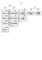
- FIG. 4 is a functional block diagram of the main part of the first embodiment.
- the description will focus on the battery module 37-1 among the battery modules 37-1 to 37-24 constituting the battery panel unit 21-1. To do.
- the CMU 32-1 constituting the battery module 37-1 measures the current flowing through the individual battery cells 61-1 to 61-10 constituting the cell module 31-1.
- Measuring unit 81, voltage measuring unit 82 for measuring voltages of individual battery cells 61-1 to 61-10 constituting cell module 31-1, and time recording unit for recording times at the time of current measurement and voltage measurement 83 is functioning.
- the BMU 36 corresponding to the CMU 32-1 constitutes a power amount calculation unit 91 and a cell module 31-1 that calculate the amount of power based on the current measured by the current measurement unit 81 and the voltage measured by the voltage measurement unit 82.
- the battery cells 61-1 to 61-10 function as an SOC calculation unit 92 for calculating the SOC when the battery cells 61-1 to 61-10 are regarded as one storage battery.
- the storage battery controller 5 that controls the battery panel unit 21-1 via the PCS 12 records the stay as a stay map corresponding to the frequency distribution pattern (histogram) of the SOC every predetermined time calculated by the SOC calculation unit 92. It functions as a control value determining unit 102 that determines a control parameter (control value) for controlling the battery panel unit 21-1 based on the map recording unit 101 and the stay map.
- FIG. 5 is a function explanatory diagram of the stay map recording unit.
- the stay map recording unit 101 acquires SOC calculation data for each predetermined measurement timing (for example, every minute) from the BMU 36 functioning as the SOC calculation unit 92.
- the SOC calculation data includes time data corresponding to the time recorded at the time of voltage measurement by the CMU 32-1 functioning as the voltage measuring unit 82 and the time recording unit 83.
- the storage battery controller 5 functioning as the unit 101 counts the detection frequency for each SOC value range (for example, SOC 5% unit) every predetermined time (for example, 1 hour). And the storage battery controller 5 which functions as the stay map recording part 101 produces
- FIG. 6 is an explanatory diagram of an SOC stay map of the first pattern.
- FIG. 7 is an explanatory diagram of an SOC stay map of the second pattern.
- the SOC is limited to 20% to 80%, and the cell module 31-1 is operated almost evenly within that range. .
- the stay map is shown when the operation is performed in consideration of long-term operation even when the amount of power that can be used is somewhat reduced.
- FIG. 8 is an explanatory diagram of a third-pattern SOC stay map.
- the cell module 31-1 when the cell module 31-1 is discharged to a state where the SOC is 0%, it is charged, but when it is charged to the state where the SOC is 50%, the operation is performed to discharge again. It is a stay map extracted in the case. That is, it becomes a stay map shown in the case of performing discharge-based operation.
- FIG. 9 is an operation processing timing chart of the first embodiment.
- the CMU 32-1 functions as the current measuring unit 81, measures the current flowing through the individual battery cells 61-1 to 61-10 constituting the cell module 31-1 (step S11), and the time recording unit. Current data is recorded in cooperation with 83 (step S12).
- the CMU 32-1 functions as the voltage measuring unit 82, measures the voltages of the individual battery cells 61-1 to 61-10 constituting the cell module 31-1 (step S13), and the time recording unit The voltage data is recorded in cooperation with 83 (step S14). Subsequently, the CMU 32-1 transmits current data and voltage data as measurement data to the BMU 36 (step S15).
- the BMU 36 When the BMU 36 receives the measurement data (step S21), the BMU 36 functions as the power amount calculation unit 91, calculates the power amount based on the measurement data, and generates power amount data (step S22).
- the BMU 36 functions as the SOC calculation unit 92, calculates the SOC of the entire cell module 31-1 based on the measurement data, and generates SOC data (step S23).
- the BMU 36 transmits the generated electric energy data and SOC data to the storage battery controller 5 as operation data at a predetermined communication timing (step S24).
- step S31 When the calculation data is received (step S31), the storage battery controller 5 performs a stay map recording process (step S32) and a control value determination process (step S33).
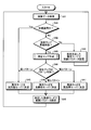
- FIG. 10 is a process flowchart of the storage battery controller. More specifically, when the storage battery controller 5 receives the calculation data (step S31), the storage battery controller 5 determines whether or not it is a predetermined initial operation period (step S41).
- step S41 If it is determined in step S41 that the predetermined initial operation period is in effect (step S41; Yes), the storage battery controller 5 determines the operation mode as the high performance mode (step S45), and controls in the high performance mode. A parameter is set (step S48), and the process proceeds to step S31 again.
- the high-performance mode is an operation mode that gives the highest priority to the maximum utilization of the SOC region (SOC range), battery capacity, and power rate for operating the storage battery system 3, and the SOC is within the allowable operation range of the storage battery system 3.
- the upper limit value and the SOC lower limit value are not provided. Accordingly, the operation mode is determined to be the high performance mode during the initial operation period, since there is no restriction on the operation status, so that the operation status of the storage battery system 3 set by the user is most reflected. This is because the operation mode is considered to be suitable for determining an operation mode suitable for the user (or application system).
- step S41 if it is not the period during the predetermined initial operation (step S41; No), that is, the initial operation period has elapsed and has ended, so the storage battery controller 5 stays in the SOC. It is determined whether or not it is time to update the map (step S42).
- the update time of the SOC stay map is changed immediately after the predetermined initial operation period has elapsed and from the previous update time of the SOC stay map for a predetermined period (for example, one month or two months, the user's operation status changes). Any period of time during which the possibility of occurrence) has elapsed.
- step S42 when it is time to update the stay map (step S42; Yes), the storage battery controller 5 creates the SOC stay map shown in FIG. 5 based on the received calculation data ( Step S43). Subsequently, the storage battery controller 5 determines the SOC stay map pattern (step S44).
- step S44 when the pattern determination result of the created SOC stay map is the first pattern shown in FIG. 6 (step S44; first pattern), the storage battery controller 5 increases the operation mode.
- the performance mode is determined (step S45), the control parameters are set in the high performance mode (step S48), and the process returns to step S31.
- step S44 when the determination result of the created stay map pattern is the second pattern shown in FIG. 7 (step S44; second pattern), the storage battery controller 5 operates in the operation mode. Is set to the long life mode (step S46), the control parameters are set in the long life mode (step S48), and the process returns to step S31.
- the long life mode is an operation mode in which deterioration control of the electric system that operates the storage battery system 3 is given top priority and the SOC region and the power rate are limited.
- the storage battery system 3 has an SOC upper limit value of 80% and an SOC lower limit value.
- the SOC upper limit value and the SOC lower limit value are not limited to the above example, and can be set as appropriate.
- step S44 when the determination result of the created stay map pattern is the third pattern shown in FIG. 8 (step S44; third pattern), the storage battery controller 5 operates in the operation mode. Is determined to be the high efficiency mode (step S47), the control parameter is set in the high efficiency mode (step S48), and the process proceeds to step S31 again.
- the user of the storage battery system 3 can select and operate an operation mode suitable for the actual operation method of the storage battery system 3.
- the SOC range that can be operated in the high-performance mode is not limited, so that the performance of the power storage system can be utilized to the maximum.
- the operation method of the user can be expected to extend the life of the power storage system, and in the high-efficiency mode, it is automatically controlled so as to suppress degradation without difficulty while extracting the performance of the power storage system from the stay map that represents the user's operation status It is possible to perform control suitable for the above.
- FIG. 11 is a principal functional block diagram of a second embodiment.
- the same parts as those in FIG. 4 are denoted by the same reference numerals, and the detailed description thereof is used.
- the second embodiment is different from the first embodiment in that a power rate calculation unit 93 that calculates the power rate of the cell module 31-1 is provided.
- FIG. 12 is an operation processing timing chart of the second embodiment.
- the CMU 32-1 operates in the same manner as in the first embodiment (steps S11 to S14), and transmits current data and voltage data to the BMU 36 as measurement data (step S15).
- the BMU 36 When the BMU 36 receives the measurement data (step S21), the BMU 36 functions as the power amount calculation unit 91, calculates the power amount based on the measurement data, and generates power amount data (step S22).
- the BMU 36 functions as the SOC calculation unit 92, calculates the SOC of the entire cell module 31-1 based on the measurement data, and generates SOC data (step S23).
- the BMU 36 functions as the power rate calculation unit 93, calculates the power rate of the cell module 31-1 based on the measurement data, and generates power rate data (step S51). Subsequently, the BMU 36 transmits the generated power amount data, SOC data, and power rate data to the storage battery controller 5 as calculation data at a predetermined communication timing (step S24).
- the storage battery controller 5 When the calculation data is received (step S31), the storage battery controller 5 performs the stay map recording process (step S32) and the control value determination process (step S33) as in the first embodiment.
- the storage battery control controller 5 will discriminate
- step S41 If it is determined in step S41 that the predetermined initial operation period is in effect (step S41; Yes), the storage battery controller 5 determines the operation mode as the high performance mode (step S45), and controls in the high performance mode. A parameter is set (step S48), and the process proceeds to step S31 again.
- step S41 if it is not the period during the predetermined initial operation (step S41; No), that is, the initial operation period has elapsed and has ended, so the storage battery controller 5 stays in the SOC. It is determined whether or not it is time to update the map and the power rate stay map (step S42).
- the update time of the stay map of the power rate is the same as the update time of the stay map of the SOC immediately after the predetermined initial operation period has passed and the update time of the stay map of the previous SOC (for example, An arbitrary period in which there is a possibility that the operation status of the user will change, such as one month or two months, is passed.
- the SOC stay map update time and the power rate update time are not necessarily the same.
- step S42 If it is determined in step S42 that it is time to update the stay map (step S42; Yes), the storage battery controller 5 determines the stay map of the SOC and the stay of the SOC shown in FIG. 5 based on the received calculation data. A stay map having the same power rate as the map is created (step S43).
- the storage battery controller 5 determines the SOC stay map and the power rate stay map pattern, respectively (step S44). Then, similarly to the first embodiment, an operation mode is set (steps S45 to S47), and control parameters relating to the SOC and the power rate are determined in the determined operation mode (step S48).
- the control parameters related to the SOC are the same as in the first embodiment.
- the control parameter related to the power rate specifically, in the high-performance mode, the highest priority is given to the maximum use of the performance of the storage battery system 3, so the control parameter is determined so as not to provide a power rate limit value. .
- the power rate at which the storage battery system 3 can be operated is limited.
- the higher the power rate the higher the amount of heat generated and the higher the temperature.
- the battery cells 61-1 to 61-10 have a high deterioration rate and the deterioration is promoted. It will be.
- control suitable for the operation method of the user of the power storage system is possible not only from the SOC but also from the viewpoint of the power rate. Become.
- FIG. 13 is a functional block diagram of the main part of a third embodiment.
- the same parts as those in FIG. The third embodiment differs from the second embodiment in that a temperature measuring unit 84 that measures the temperature of each of the battery cells 61-1 to 61-10 is provided.
- the individual battery cells 61-1 that actually constitute the storage battery system 3 even with the power rate 3P. ⁇ 61-10 may not reach a high temperature. In such a case, the power rate is excessively limited, and as a result, the performance of the storage battery system 3 may be lowered.
- the temperature of the individual battery cells 61-1 to 61-10 is measured by the temperature measuring unit 84, so that the power rate is not excessively limited.
- the power rate when the maximum temperature during the period during which the stay map relating to the power rate is created and the maximum temperature is lower than a predetermined set temperature corresponding to the boundary temperature at which the deterioration rate of the power storage system is accelerated, the power rate The limit value is relaxed, and if the temperature is higher than a predetermined set temperature, the limit value of the power rate is tightened.
- the temperature of the individual battery cells 61-1 to 61-10 constituting the storage battery system 3 is taken into consideration, thereby It is possible to avoid the performance degradation of the storage battery system 3 due to the excessive limitation of the rate.
- FIG. 14 is a principal functional block diagram of a fourth embodiment.
- the same components as those in FIG. 11 are denoted by the same reference numerals, and the detailed description thereof is incorporated.
- the fourth embodiment is different from the second embodiment in that a current rate calculation unit 94 that calculates the current rate of the cell module 31-1 is provided instead of the power rate calculation unit 93, and a current rate stay map is used. This is the point to control.
- control suitable for the operation method of the user of the power storage system is possible not only from the SOC but also from the viewpoint of the current rate. That is, as in the second embodiment described above, for example, when the maximum current rate is limited to 2X from the current rate stay map, the individual battery cells 61-1 that actually constitute the storage battery system 3 even at the current rate 3X. In some cases, ⁇ 61-10 does not reach a high temperature. In such a case, the current rate is excessively limited, and as a result, the performance of the storage battery system 3 may be lowered.
- the current rate of each of the battery cells 61-1 to 61-10 is measured by the current rate calculation unit 94 so that the power rate is not excessively limited.
- the control parameters related to the SOC are the same as those in the first embodiment.
- control parameter relating to the current rate specifically, in the high-performance mode, the highest priority is given to the maximum use of the performance of the storage battery system 3, so the control parameter is determined so as not to provide a current rate limit value. . *
- the current rate at which the storage battery system 3 can be operated is limited.
- the higher the current rate the higher the amount of heat generated and the higher the temperature.
- the battery cells 61-1 to 61-10 have a high deterioration rate and the deterioration is promoted. It will be.
- control suitable for the operation method of the user of the power storage system is possible not only from the SOC but also from the viewpoint of the current rate. Become.
- FIG. 15 is a principal functional block diagram of a fifth embodiment.
- the same parts as those in FIG. 15 are identical to FIG. 15 in FIG. 15, the same parts as those in FIG. 15 in FIG. 15, the same parts as those in FIG. 15
- the fifth embodiment differs from the fourth embodiment in that a temperature measuring unit 84 that measures the temperature of each of the battery cells 61-1 to 61-10 is provided.
- a temperature measuring unit 84 that measures the temperature of each of the battery cells 61-1 to 61-10 is provided.
- the storage battery controller 5 of the storage battery system of the present embodiment includes a control device such as a CPU, a storage device such as a ROM (Read Only Memory) and a RAM, an external storage device such as an HDD and a CD drive device, and a display device.
- a control device such as a CPU
- a storage device such as a ROM (Read Only Memory) and a RAM
- an external storage device such as an HDD and a CD drive device
- a display device a display device and an input device such as a keyboard and a mouse are provided, and a hardware configuration using a normal computer is employed.
- the program executed by the storage battery controller 5 of the storage battery system of the present embodiment is a file in an installable format or an executable format, and is a CD-ROM, flexible disk (FD), CD-R, DVD (Digital Versatile Disk). Or the like recorded on a computer-readable recording medium.
- the program executed by the storage battery controller 5 of the storage battery system of the present embodiment may be stored on a computer connected to a network such as the Internet and provided by being downloaded via the network. . Moreover, you may comprise so that the program run with the storage battery management apparatus of this embodiment may be provided or distributed via networks, such as the internet. Moreover, you may comprise so that the program of the storage battery control controller 5 of the storage battery system of this embodiment may be provided by previously incorporating in ROM etc.
- part or all of the processing performed by the middle-level control device such as the BMU 36 may be performed by the storage battery control controller 5 or a higher-level higher-level control device (not shown).
- a part or all of the processing performed by the intermediate control device such as the BMU 36 may be performed by the CMU that is the lower control device.
- a form in which some or all of the processing performed by lower-level devices such as each CMU is performed by a middle-level control device such as a BMU, the storage battery controller 5 or a higher-level control device may be employed.
- a part or all of the processing performed by the host control device such as the storage battery controller 5 may be performed by a middle control device such as BMU or a lower control device such as CMU.
- the storage battery controller 5 performs the functions of the stay map recording unit 101 and the control value determination unit 102.
- the host controller 6 or the PCS 12 may perform the configuration, or may be distributed to each unit. It is also possible to arrange them.
Landscapes
- Engineering & Computer Science (AREA)
- Manufacturing & Machinery (AREA)
- Chemical & Material Sciences (AREA)
- Chemical Kinetics & Catalysis (AREA)
- Electrochemistry (AREA)
- General Chemical & Material Sciences (AREA)
- Power Engineering (AREA)
- Charge And Discharge Circuits For Batteries Or The Like (AREA)
- Supply And Distribution Of Alternating Current (AREA)
- Secondary Cells (AREA)
Abstract
実施形態の蓄電池システムの記憶部は、蓄電池装置のSOCの度数分布パターンと蓄電池装置の制御パラメータとの対応関係を予め記憶し、決定部は、当該蓄電池システムの運用時に所定時間毎に測定された蓄電池装置のSOCの所定期間の度数分布についてSOCの度数分布パターンを判別し、記憶部を参照して蓄電池装置の制御パラメータを決定するので、ユーザ(あるいは適用システム)に見合った運用モードを提示もしくは自動制御することができる。
Description
本発明の実施形態は、蓄電池システム、方法及びプログラムに関する。
近年、リチウムイオン電池のようなエネルギー密度が高く、長寿命の二次電池が開発され、車載用の蓄電池システムとしての利用に留まらず、電力系統の安定化を目的とした定置型の蓄電池システム等への利用が拡大している。
これらの蓄電システムの運用方法はユーザ(あるいは、適用システム)によって大きく異なり、例えば、蓄電システムの寿命は気にせず放電深度を深く使用したいや、多少の蓄電システムの使用制限を受けたとしても長く使い続けたいなど様々である。
そこで、蓄電システムの使用条件や使用状況から判断してそのユーザ(あるいは適用システム)に見合った運用モードを提示もしくは自動制御してくれる電池状態診断システムが望まれている。
しかしながら、従来の電池状態診断システムは、例えば、電池の寿命改善に用いることができるだけであり、必ずしも、ユーザ(あるいは適用システム)に見合った運用モードを提示もしくは自動制御するものではなかった。
本発明は、上記に鑑みてなされたものであって、ユーザ(あるいは適用システム)に見合った運用モードを提示もしくは自動制御することが可能な蓄電池システム、方法及びプログラムを提供することを目的としている。
実施形態の蓄電池システムの記憶部は、蓄電池装置のSOCの度数分布パターンと蓄電池装置の制御パラメータとの対応関係を予め記憶する。
決定部は、当該蓄電池システムの運用時に所定時間毎に測定された蓄電池装置のSOCの所定期間の度数分布についてSOCの度数分布パターンを判別し、記憶部を参照して蓄電池装置の制御パラメータを決定する。
決定部は、当該蓄電池システムの運用時に所定時間毎に測定された蓄電池装置のSOCの所定期間の度数分布についてSOCの度数分布パターンを判別し、記憶部を参照して蓄電池装置の制御パラメータを決定する。
次に図面を参照して実施形態について説明する。
図1は、実施形態の蓄電池システムを備えた自然エネルギー発電システムの概要構成図である。
図1は、実施形態の蓄電池システムを備えた自然エネルギー発電システムの概要構成図である。
自然エネルギー発電システム100は、電力システムとして機能し、太陽光、水力、風力、バイオマス、地熱等の自然エネルギー(再生可能エネルギー)を利用し、系統電力として出力可能な自然エネルギー発電ユニット1と、自然エネルギー発電ユニット1の発電電力を測定する電力計2と、風力、電力計2の測定結果に基づいて自然エネルギー発電ユニット1の余剰電力を充電し、不足電力を放電して自然エネルギー発電ユニット1の発電電力に重畳して出力する蓄電池システム3と、自然エネルギー発電ユニット1の出力電力(蓄電池システム3の出力電力が重畳されている場合も含む)の電圧変換を行う変圧器4と、蓄電池システム3のローカルな制御を行う蓄電池制御コントローラ5と、蓄電池制御コントローラ5のリモート制御を行う上位制御装置6と、を備えている。
図2は、実施形態の蓄電池システムの概要構成ブロック図である。
蓄電池システム3は、大別すると、電力を蓄える蓄電池装置11と、蓄電池装置11から供給された直流電力を所望の電力品質を有する交流電力に変換して負荷に供給する電力変換装置(PCS:Power Conditioning System)12と、を備えている。
蓄電池システム3は、大別すると、電力を蓄える蓄電池装置11と、蓄電池装置11から供給された直流電力を所望の電力品質を有する交流電力に変換して負荷に供給する電力変換装置(PCS:Power Conditioning System)12と、を備えている。
蓄電池装置11は、大別すると、複数の電池盤ユニット21-1~21-N(Nは自然数)と、電池盤ユニット21-1~21-Nが接続された電池端子盤22と、を備えている。
電池盤ユニット21-1~21-Nは、互いに並列に接続された複数の電池盤23-1~23-M(Mは自然数)と、ゲートウェイ装置24と、後述のBMU(Battery Management Unit:電池管理装置)及びCMU(Cell Monitoring Unit:セル監視装置)に動作用の直流電源を供給する直流電源装置25と、を備えている。
電池盤ユニット21-1~21-Nは、互いに並列に接続された複数の電池盤23-1~23-M(Mは自然数)と、ゲートウェイ装置24と、後述のBMU(Battery Management Unit:電池管理装置)及びCMU(Cell Monitoring Unit:セル監視装置)に動作用の直流電源を供給する直流電源装置25と、を備えている。
ここで、電池ユニットの構成について説明する。
電池盤23-1~23-Mは、それぞれ、高電位側電源供給ライン(高電位側電源供給線)LH及び低電位側電源供給ライン(低電位側電源供給線)LLを介して、出力電源ライン(出力電源線;母線)LHO、LLOに接続され、主回路である電力変換装置12に電力を供給している。
電池盤23-1~23-Mは、それぞれ、高電位側電源供給ライン(高電位側電源供給線)LH及び低電位側電源供給ライン(低電位側電源供給線)LLを介して、出力電源ライン(出力電源線;母線)LHO、LLOに接続され、主回路である電力変換装置12に電力を供給している。
電池盤23-1~23-Mは、同一構成であるので、電池盤23-1を例として説明する。
電池盤23-1は、大別すると、複数(図1では、24個)のセルモジュール31-1~31-24と、セルモジュール31-1~31-24にそれぞれ設けられた複数(図1では、24個)のCMU32-1~32-24と、セルモジュール31-12とセルモジュール31-13との間に設けられたサービスディスコネクト33と、電流センサ34と、コンタクタ35と、を備え、複数のセルモジュール31-1~31-24、サービスディスコネクト33、電流センサ34及びコンタクタ35は、直列に接続されている。
電池盤23-1は、大別すると、複数(図1では、24個)のセルモジュール31-1~31-24と、セルモジュール31-1~31-24にそれぞれ設けられた複数(図1では、24個)のCMU32-1~32-24と、セルモジュール31-12とセルモジュール31-13との間に設けられたサービスディスコネクト33と、電流センサ34と、コンタクタ35と、を備え、複数のセルモジュール31-1~31-24、サービスディスコネクト33、電流センサ34及びコンタクタ35は、直列に接続されている。
ここで、セルモジュール31-1~31-24は、電池セルを複数、直並列に接続されて組電池を構成している。そして、複数の直列接続されたセルモジュール31-1~31-24で組電池群を構成している。
さらに電池盤23-1は、BMU36を備え、各CMU32-1~32-24の通信ライン、電流センサ34の出力ラインは、BMU36に接続されている。
BMU36は、ゲートウェイ装置24の制御下で、電池盤23-1全体を制御し、各CMU32-1~32-24との通信結果(後述する電圧データ及び温度データ)及び電流センサ34の検出結果に基づいてコンタクタ35の開閉制御を行う。
BMU36は、ゲートウェイ装置24の制御下で、電池盤23-1全体を制御し、各CMU32-1~32-24との通信結果(後述する電圧データ及び温度データ)及び電流センサ34の検出結果に基づいてコンタクタ35の開閉制御を行う。
次に電池端子盤の構成について説明する。
電池端子盤22は、電池盤ユニット21-1~21-Nに対応させて設けられた複数の盤遮断器41-1~41-Nと、蓄電池装置11全体を制御するマイクロコンピュータとして構成されたマスタ(Master)装置42と、を備えている。
電池端子盤22は、電池盤ユニット21-1~21-Nに対応させて設けられた複数の盤遮断器41-1~41-Nと、蓄電池装置11全体を制御するマイクロコンピュータとして構成されたマスタ(Master)装置42と、を備えている。
マスタ装置42には、電力変換装置12との間に、電力変換装置12のUPS(Uninterruptible Power System)12Aを介して供給される制御電源線51と、イーサネット(登録商標)として構成され、制御データのやりとりを行う制御通信線52と、が接続されている。
ここで、セルモジュール31-1~31-24、CMU32-1~32-24およびBMU36の詳細構成について説明する。
図3は、セルモジュール、CMU及びBMUの詳細構成説明図である。
セルモジュール31-1~31-24は、それぞれ、直列接続された複数(図2では、101個)の電池セル61-1~61-10を備えている。
セルモジュール31-1~31-24は、それぞれ、直列接続された複数(図2では、101個)の電池セル61-1~61-10を備えている。
CMU32-1~32-24は、対応するセルモジュール31-1~31-24を構成している電池セル61-1~61-10の電流、電圧及び所定箇所の温度を測定するための電流電圧温度計測IC(Analog Front End IC:AFE-IC)62と、それぞれが対応するCMU32-1~32-24全体の制御を行うMPU63と、BMU36との間でCAN通信を行うためのCAN(Controller Area Network)規格に則った通信コントローラ64と、セル毎の電圧に相当する電圧データ及び温度データを格納するメモリ65と、を備えている。
以下の説明において、セルモジュール31-1~31-24のそれぞれと、対応するCMU32-1~32-24と、を合わせた構成については、電池モジュール37-1~37-24と呼ぶものとする。例えば、セルモジュール31-1と対応するCMU32-1を合わせた構成を電池モジュール37-1と呼ぶものとする。
また、BMU36は、BMU36全体を制御するMPU71と、CMU32-1~32-24との間でCAN通信を行うためのCAN規格に則った通信コントローラ72と、CMU32-1~32-24から送信された電圧データ及び温度データを格納するメモリ73と、を備えている。
蓄電池制御コントローラ5は、自然エネルギー発電ユニット1の発電電力を検出し、この発電電力が電力系統へ及ぼす影響を緩和するために、蓄電池装置11を用いて発電電力の出力変動抑制を行なっている。ここで、蓄電池装置11に対する変動抑制量は当該蓄電池制御コントローラ5あるいはその上位制御装置6で算出し、蓄電池装置11に対応するPCS(Power Conditioning System)12に充放電指令として与えられる。
[1]第1実施形態
次に第1実施形態について詳細に説明する。
図4は、第1実施形態の要部機能ブロック図である。
以下の説明においては、説明の簡略化及び理解の容易のため、電池盤ユニット21-1を構成している電池モジュール37-1~37-24のうち、電池モジュール37-1に着目して説明する。
次に第1実施形態について詳細に説明する。
図4は、第1実施形態の要部機能ブロック図である。
以下の説明においては、説明の簡略化及び理解の容易のため、電池盤ユニット21-1を構成している電池モジュール37-1~37-24のうち、電池モジュール37-1に着目して説明する。
電池モジュール37-1を構成しているCMU32-1は、図4に示すように、セルモジュール31-1を構成している個々の電池セル61-1~61-10に流れる電流を計測する電流計測部81、セルモジュール31-1を構成している個々の電池セル61-1~61-10の電圧を計測する電圧計測部82及び電流計測時及び電圧計測時の時刻を記録する時刻記録部83として機能している。
また、CMU32-1に対応するBMU36は、電流計測部81が計測した電流及び電圧計測部82が計測した電圧に基づいて電力量を演算する電力量演算部91及びセルモジュール31-1を構成している電池セル61-1~61-10全体を一つの蓄電池とみなした場合のSOCを演算するSOC演算部92として機能している。
またPCS12を介して電池盤ユニット21-1を制御する蓄電池制御コントローラ5は、SOC演算部92が演算したSOCの所定時間毎の推移の度数分布パターン(ヒストグラム)に対応する滞在マップとして記録する滞在マップ記録部101及び滞在マップに基づいて電池盤ユニット21-1を制御するための制御パラメータ(制御値)を決定する制御値決定部102として機能している。
ここで、第1実施形態の動作説明に先立ち、滞在マップと制御パラメータとの対応関係について説明する。
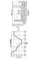
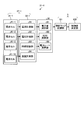
図5は、滞在マップ記録部の機能説明図である。
図5の左部分に示すように、滞在マップ記録部101は、SOC演算部92として機能しているBMU36から所定の測定タイミング(例えば、1分毎)毎のSOC演算データを取得する。
図5は、滞在マップ記録部の機能説明図である。
図5の左部分に示すように、滞在マップ記録部101は、SOC演算部92として機能しているBMU36から所定の測定タイミング(例えば、1分毎)毎のSOC演算データを取得する。
この場合において、SOC演算データには、電圧計測部82及び時刻記録部83として機能しているCMU32-1により電圧測定時に記録された時刻に対応する時刻データが含まれているので、滞在マップ記録部101として機能する蓄電池制御コントローラ5は、所定の時間(例えば、1時間)毎にSOCの値領域(例えば、SOC5%単位)毎に検出度数をカウントする。
そして、滞在マップ記録部101として機能する蓄電池制御コントローラ5は、カウントした検出度数に基づいてSOCの滞在マップ(度数分布パターン)を生成する。
そして、滞在マップ記録部101として機能する蓄電池制御コントローラ5は、カウントした検出度数に基づいてSOCの滞在マップ(度数分布パターン)を生成する。
ここで、典型的なSOCの滞在マップについて図面を参照して説明する。
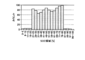
図6は、第1パターンのSOCの滞在マップの説明図である。
図6の場合は、セルモジュール31-1を一つの蓄電池とみなした場合に、SOC=0%~100%の間でほぼ均等に運用している場合のものである。
図6は、第1パターンのSOCの滞在マップの説明図である。
図6の場合は、セルモジュール31-1を一つの蓄電池とみなした場合に、SOC=0%~100%の間でほぼ均等に運用している場合のものである。
例えば、セルモジュール31-1をSOC=100%の状態に充電した後、SOC=0%の状態にまで徐々に放電して電力を供給するような運用の仕方を行っている場合に抽出される滞在マップである。すなわち、多少、蓄電池システム3の寿命は低下しても、使用可能な電力量を重視するような運用を行う場合に示される滞在マップである。
図7は、第2パターンのSOCの滞在マップの説明図である。
図7の場合は、セルモジュール31-1を一つの蓄電池とみなした場合に、SOC=20%~80%の間に制限して、その範囲でほぼ均等に運用している場合のものである。
図7の場合は、セルモジュール31-1を一つの蓄電池とみなした場合に、SOC=20%~80%の間に制限して、その範囲でほぼ均等に運用している場合のものである。
例えば、セルモジュール31-1を構成している電池セル61-1~61-10の劣化を抑制しつつ、セルモジュール31-1の安定した長期運用を考慮し、SOC=20%の状態まで放電したら、SOC=80%の状態まで充電し、その後再びSOC=20%の状態まで放電する動作を繰り返し、常時行うような運用の仕方を行っている場合に抽出される滞在マップである。すなわち、多少使用可能な電力量は少なくなっても、長期運用を考慮して運用を行う場合に示される滞在マップである。
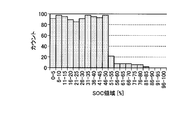
図8は、第3パターンのSOCの滞在マップの説明図である。
図8の場合は、セルモジュール31-1を一つの蓄電池とみなした場合に、SOC=0%~50%の範囲でほぼ均等に運用している場合のものである。
図8の場合は、セルモジュール31-1を一つの蓄電池とみなした場合に、SOC=0%~50%の範囲でほぼ均等に運用している場合のものである。
例えば、セルモジュール31-1をSOC=0%の状態まで使い切った状態まで放電したら、充電を行うが、SOC=50%の状態まで充電すると、再び放電を行うような運用の仕方を行っている場合に抽出される滞在マップである。すなわち放電主体の運用を行う場合に示される滞在マップとなる。
このように、本第1実施形態では、SOCの滞在マップを作成することで蓄電システムの運用状況を診断し、その結果から制御値決定部において制御パラメータを決定する。
次に第1実施形態の動作を説明する。
図9は、第1実施形態の動作処理タイミングチャートである。
次に第1実施形態の動作を説明する。
図9は、第1実施形態の動作処理タイミングチャートである。
まず、CMU32-1は、電流計測部81として機能し、セルモジュール31-1を構成している個々の電池セル61-1~61-10に流れる電流を計測し(ステップS11)、時刻記録部83と共働して電流データを記録する(ステップS12)。
続いて、CMU32-1は、電圧計測部82として機能し、セルモジュール31-1を構成している個々の電池セル61-1~61-10の電圧を計測し(ステップS13)、時刻記録部83と共働して電圧データを記録する(ステップS14)。
続いてCMU32-1は、電流データ及び電圧データを計測データとしてBMU36に送信する(ステップS15)。
続いてCMU32-1は、電流データ及び電圧データを計測データとしてBMU36に送信する(ステップS15)。
BMU36は、計測データを受信すると(ステップS21)、電力量演算部91として機能し、計測データに基づいて電力量を演算して電力量データを生成する(ステップS22)。
続いてBMU36は、SOC演算部92として機能し、計測データに基づいて、セルモジュール31-1全体のSOCを演算してSOCデータを生成する(ステップS23)。
続いてBMU36は、所定の通信タイミングにおいて、生成した電力量データ及びSOCデータを演算データとして蓄電池制御コントローラ5に送信する(ステップS24)。
演算データを受信すると(ステップS31)、蓄電池制御コントローラ5は、滞在マップの記録処理(ステップS32)及び制御値決定処理(ステップS33)を行う。
図10は、蓄電池制御コントローラの処理フローチャートである。
より詳細には、蓄電池制御コントローラ5は、演算データを受信すると(ステップS31)、所定の初期運用中の期間であるか否かを判別する(ステップS41)。
より詳細には、蓄電池制御コントローラ5は、演算データを受信すると(ステップS31)、所定の初期運用中の期間であるか否かを判別する(ステップS41)。
ステップS41の判別において、所定の初期運用中の期間である場合には(ステップS41;Yes)、蓄電池制御コントローラ5は、動作モードを高性能モードに決定し(ステップS45)、高性能モードで制御パラメータを設定し(ステップS48)、処理を再びステップS31に移行する。
ここで、高性能動作モード及び初期運用中の期間である場合に動作モードを高性能モードに決定する理由について説明する。
高性能モードは、蓄電池システム3を運用するSOC領域(SOC範囲)、電池容量、電力レートを最大限利用することを最優先する動作モードであり、蓄電池システム3の許容動作範囲内である限りSOC上限値及びSOC下限値は設けない動作モードである。
したがって、初期運用中の期間である場合に動作モードを高性能モードに決定するのは、運用状況に何らの制限が設けられないので、ユーザにより設定された蓄電池システム3の運用状況が最も反映され、ユーザ(あるいは適用システム)に見合った動作モードを判別するのに適していると考えられる動作モードだからである。
高性能モードは、蓄電池システム3を運用するSOC領域(SOC範囲)、電池容量、電力レートを最大限利用することを最優先する動作モードであり、蓄電池システム3の許容動作範囲内である限りSOC上限値及びSOC下限値は設けない動作モードである。
したがって、初期運用中の期間である場合に動作モードを高性能モードに決定するのは、運用状況に何らの制限が設けられないので、ユーザにより設定された蓄電池システム3の運用状況が最も反映され、ユーザ(あるいは適用システム)に見合った動作モードを判別するのに適していると考えられる動作モードだからである。
ステップS41の判別において、所定の初期運用中の期間ではない場合には(ステップS41;No)、すなわち、初期運用期間が経過し、終了した状態であるので、蓄電池制御コントローラ5は、SOCの滞在マップの更新時期であるか否かを判別する(ステップS42)。
ここで、SOCの滞在マップの更新時期は、所定の初期運用期間が経過した直後および前回のSOCの滞在マップの更新時期から所定の期間(例えば、1ヶ月または2ヶ月などユーザの運用状況が変化する可能性が生じると考えられる任意の期間)が経過した時点とされる。
ステップS42の判別において、滞在マップの更新時期である場合には(ステップS42;Yes)、蓄電池制御コントローラ5は、受信した演算データに基づいて、図5に示したSOCの滞在マップを作成する(ステップS43)。
続いて、蓄電池制御コントローラ5は、SOCの滞在マップのパターンを判別する(ステップS44)。
続いて、蓄電池制御コントローラ5は、SOCの滞在マップのパターンを判別する(ステップS44)。
ステップS44の判別において、作成されたSOCの滞在マップのパターン判別結果が図6に示した第1パターンである場合には(ステップS44;第1パターン)、蓄電池制御コントローラ5は、動作モードを高性能モードに決定し(ステップS45)、高性能モードで制御パラメータを設定し(ステップS48)、処理を再びステップS31に移行する。
同様に、ステップS44の判別において、作成された滞在マップのパターンの判別結果が図7に示した第2パターンである場合には(ステップS44;第2パターン)、蓄電池制御コントローラ5は、動作モードを長寿命モードに決定し(ステップS46)、長寿命モードで制御パラメータを設定し(ステップS48)、処理を再びステップS31に移行する。
ここで、長寿命モードについて説明する。
長寿命モードは、蓄電池システム3を運用する電システムの劣化抑制を最優先とし、SOC領域や電力レートを制限する動作モードであり、蓄電池システム3は、例えば、SOC上限値を80%、SOC下限値を20%として運用できるSOC領域をSOC=20%からSOC=80%までに制限する。
長寿命モードは、蓄電池システム3を運用する電システムの劣化抑制を最優先とし、SOC領域や電力レートを制限する動作モードであり、蓄電池システム3は、例えば、SOC上限値を80%、SOC下限値を20%として運用できるSOC領域をSOC=20%からSOC=80%までに制限する。
これは、充電末(SOC=100%)、あるいは、放電末(SOC=0%)の近傍のSOCの状態で、滞在すると、電池セル61-1~61-10の劣化が促進されてしまうため(劣化速度が速いため)、ひいては、蓄電池システムの運用期間が短くなるのを防止するためである。この場合において、SOC上限値及びSOC下限値については、上記例に限らず、適宜設定することが可能である。
同様に、ステップS44の判別において、作成された滞在マップのパターンの判別結果が図8に示した第3パターンである場合には(ステップS44;第3パターン)、蓄電池制御コントローラ5は、動作モードを高効率モードに決定し(ステップS47)、高効率モードで制御パラメータを設定し(ステップS48)、処理を再びステップS31に移行する。
ここで、高効率モードについて説明する。
高効率モードは、ユーザの運用状況に応じて制御パラメータを最適値に設定する動作モードであり、例えば、運用領域がSOC=0%からSOC=50%までと偏っていることが判明した場合は、劣化が促進される放電末での運用は避け、かつ、SOCの運用領域幅は変わらずに50%となるようにSOC上限値75%、SOC下限値25%と設定する(この場合に、SOC50%を中央値とするのが好ましい)。
高効率モードは、ユーザの運用状況に応じて制御パラメータを最適値に設定する動作モードであり、例えば、運用領域がSOC=0%からSOC=50%までと偏っていることが判明した場合は、劣化が促進される放電末での運用は避け、かつ、SOCの運用領域幅は変わらずに50%となるようにSOC上限値75%、SOC下限値25%と設定する(この場合に、SOC50%を中央値とするのが好ましい)。
以上の説明の様に、SOCの滞在マップが作成されることで、容易に蓄電池システム3の運用状況を容易かつ確実に判別することが可能となる。
したがって、本第1実施形態によれば、蓄電池システム3のユーザは、実際の蓄電池システム3の運用方法に適した運用モードを選択して運用することが可能となる。
したがって、本第1実施形態によれば、蓄電池システム3のユーザは、実際の蓄電池システム3の運用方法に適した運用モードを選択して運用することが可能となる。
例えば、高性能モードでは運用できるSOC領域に制限をかけないため蓄電システムの性能を最大限活用することができ、長寿命モードでは劣化速度が速い領域である充放電末を避ける制御をすることで蓄電システムの長寿命化が望め、高効率モードではユーザの運用状況を表す滞在マップから蓄電システムの性能を引き出しつつ無理なく劣化を抑制するように自動的に制御されるように、ユーザの運用方法に適した制御が可能となる。
[2]第2実施形態
図11は、第2実施形態の要部機能ブロック図である。
図11において、図4と同様の部分には、同一の符号を付し、その詳細な説明を援用する。
第2実施形態が第1実施形態と異なる点は、セルモジュール31-1の電力レートを演算する電力レート演算部93を備えた点である。
図11は、第2実施形態の要部機能ブロック図である。
図11において、図4と同様の部分には、同一の符号を付し、その詳細な説明を援用する。
第2実施形態が第1実施形態と異なる点は、セルモジュール31-1の電力レートを演算する電力レート演算部93を備えた点である。
次に第2実施形態の動作を説明する。
図12は、第2実施形態の動作処理タイミングチャートである。
図12は、第2実施形態の動作処理タイミングチャートである。
まず、CMU32-1は、第1実施形態と同様に動作し(ステップS11~S14)、電流データ及び電圧データを計測データとしてBMU36に送信する(ステップS15)。
BMU36は、計測データを受信すると(ステップS21)、電力量演算部91として機能し、計測データに基づいて電力量を演算して電力量データを生成する(ステップS22)。
続いてBMU36は、SOC演算部92として機能し、計測データに基づいて、セルモジュール31-1全体のSOCを演算してSOCデータを生成する(ステップS23)。
続いてBMU36は、電力レート演算部93として機能し、計測データに基づいて、セルモジュール31-1の電力レートを演算して電力レートデータを生成する(ステップS51)。
続いてBMU36は、所定の通信タイミングにおいて、生成した電力量データ、SOCデータ及び電力レートデータを演算データとして蓄電池制御コントローラ5に送信する(ステップS24)。
続いてBMU36は、所定の通信タイミングにおいて、生成した電力量データ、SOCデータ及び電力レートデータを演算データとして蓄電池制御コントローラ5に送信する(ステップS24)。
演算データを受信すると(ステップS31)、蓄電池制御コントローラ5は、滞在マップの記録処理(ステップS32)及び制御値決定処理(ステップS33)を第1実施形態と同様に行う。
以下、再び図10を参照して、第2実施形態の動作を説明する。
そして、蓄電池制御コントローラ5は、演算データを受信すると(ステップS31)、所定の初期運用中の期間であるか否かを判別する(ステップS41)。
そして、蓄電池制御コントローラ5は、演算データを受信すると(ステップS31)、所定の初期運用中の期間であるか否かを判別する(ステップS41)。
ステップS41の判別において、所定の初期運用中の期間である場合には(ステップS41;Yes)、蓄電池制御コントローラ5は、動作モードを高性能モードに決定し(ステップS45)、高性能モードで制御パラメータを設定し(ステップS48)、処理を再びステップS31に移行する。
ステップS41の判別において、所定の初期運用中の期間ではない場合には(ステップS41;No)、すなわち、初期運用期間が経過し、終了した状態であるので、蓄電池制御コントローラ5は、SOCの滞在マップ及び電力レート滞在マップの更新時期であるか否かを判別する(ステップS42)。
ここで、電力レートの滞在マップの更新時期は、SOCの滞在マップの更新時期と同様に、所定の初期運用期間が経過した直後および前回のSOCの滞在マップの更新時期から所定の期間(例えば、1ヶ月または2ヶ月などユーザの運用状況が変化する可能性が生じると考えられる任意の期間)が経過した時点とされる。なお、SOCの滞在マップの更新時期と、電力レートの更新時期とは必ずしも同じにする必要はない。
ステップS42の判別において、滞在マップの更新時期である場合には(ステップS42;Yes)、蓄電池制御コントローラ5は、受信した演算データに基づいて、図5に示したSOCの滞在マップ及びSOCの滞在マップと同様な電力レートの滞在マップを作成する(ステップS43)。
続いて、蓄電池制御コントローラ5は、SOCの滞在マップ及び電力レートの滞在マップのパターンをそれぞれ判別する(ステップS44)。
そして第1実施形態と同様に動作モードを設定し(ステップS45~S47)、決定した動作モードでSOC及び電力レートに関する制御パラメータを決定する(ステップS48)。
そして第1実施形態と同様に動作モードを設定し(ステップS45~S47)、決定した動作モードでSOC及び電力レートに関する制御パラメータを決定する(ステップS48)。
SOCに関する制御パラメータについては、第1実施形態と同様である。
また電力レートに関する制御パラメータに関しては、具体的には、高性能モードでは、蓄電池システム3の性能を最大限利用することを最優先するため、電力レート制限値は設けないように制御パラメータを決定する。
また、長寿命モードでは、蓄電池システム3が運用できる電力レートを制限する。蓄電池システム3は、電力レートが大きいほど発熱量が多くなるため高温になり、高温な状態で保持されると、電池セル61-1~61-10は、劣化速度が速く劣化が促進されてしまうこととなる。
また電力レートに関する制御パラメータに関しては、具体的には、高性能モードでは、蓄電池システム3の性能を最大限利用することを最優先するため、電力レート制限値は設けないように制御パラメータを決定する。
また、長寿命モードでは、蓄電池システム3が運用できる電力レートを制限する。蓄電池システム3は、電力レートが大きいほど発熱量が多くなるため高温になり、高温な状態で保持されると、電池セル61-1~61-10は、劣化速度が速く劣化が促進されてしまうこととなる。
そこで、例えば、最大電力レート5Pで運用できる蓄電池システム3の場合には、最大電力レート2Pに制限すればよい。
以上の説明の様に、本第2実施形態によれば、第1実施形態の効果に加えて、SOCだけでなく電力レートの観点からも蓄電システムのユーザの運用方法に適した制御が可能となる。
以上の説明の様に、本第2実施形態によれば、第1実施形態の効果に加えて、SOCだけでなく電力レートの観点からも蓄電システムのユーザの運用方法に適した制御が可能となる。
[3]第3実施形態
図13は、第3実施形態の要部機能ブロック図である。
図13において、図11と同様の部分には、同一の符号を付し、その詳細な説明を援用する。
第3実施形態が第2実施形態と異なる点は、個々の電池セル61-1~61-10の温度を計測する温度計測部84を備えた点である。
図13は、第3実施形態の要部機能ブロック図である。
図13において、図11と同様の部分には、同一の符号を付し、その詳細な説明を援用する。
第3実施形態が第2実施形態と異なる点は、個々の電池セル61-1~61-10の温度を計測する温度計測部84を備えた点である。
上述した第2実施形態で示したように、例えば、電力レートの滞在マップから最大電力レートを2Pと制限した場合、実際は電力レート3Pでも蓄電池システム3を構成している個々の電池セル61-1~61-10は高温にはならない場合があり、このような場合には、電力レートを過剰に制限してしまうこととなり、結果的に蓄電池システム3の性能を低くしてしまう虞がある。
そこで、本第3実施形態においては、個々の電池セル61-1~61-10の温度を温度計測部84により計測することで、電力レートを過剰に制限することはなくなる。
より詳細には、電力レートに関する滞在マップを作成した期間中の最高温度を用い、その最高温度が蓄電システムの劣化速度が速くなる境界温度に相当する所定の設定温度より低い場合は、電力レートの制限値を緩め、所定の設定温度より高い場合は電力レートの制限値を厳しくする。
この結果、本第3実施形態によれば、第2実施形態の効果に加えて、蓄電池システム3を構成している個々の電池セル61-1~61-10の温度を考慮することで、電力レートの過剰制限に起因する、蓄電池システム3の性能低下を回避することができる。
[4]第4実施形態
図14は、第4実施形態の要部機能ブロック図である。
図14において、図11と同様の部分には、同一の符号を付し、その詳細な説明を援用する。
図14は、第4実施形態の要部機能ブロック図である。
図14において、図11と同様の部分には、同一の符号を付し、その詳細な説明を援用する。
第4実施形態が第2実施形態と異なる点は、電力レート演算部93に代えて、セルモジュール31-1の電流レートを演算する電流レート演算部94を備え、電流レートの滞在マップを用いて制御を行う点である。
本第4実施形態によれば、第1実施形態の効果に加えて、SOCだけでなく電流レートの観点からも蓄電システムのユーザの運用方法に適した制御が可能となる。
すなわち、上述した第2実施形態と同様に、例えば、電流レートの滞在マップから最大電流レートを2Xと制限した場合、実際は電流レート3Xでも蓄電池システム3を構成している個々の電池セル61-1~61-10は高温にはならない場合があり、このような場合には、電流レートを過剰に制限してしまうこととなり、結果的に蓄電池システム3の性能を低くしてしまう虞がある。
すなわち、上述した第2実施形態と同様に、例えば、電流レートの滞在マップから最大電流レートを2Xと制限した場合、実際は電流レート3Xでも蓄電池システム3を構成している個々の電池セル61-1~61-10は高温にはならない場合があり、このような場合には、電流レートを過剰に制限してしまうこととなり、結果的に蓄電池システム3の性能を低くしてしまう虞がある。
そこで、本第4実施形態においては、個々の電池セル61-1~61-10の電流レートを電流レート演算部94により計測することで、電力レートを過剰に制限しないようにしている。
この場合に、SOCに関する制御パラメータについては、第1実施形態と同様である。
この場合に、SOCに関する制御パラメータについては、第1実施形態と同様である。
また電流レートに関する制御パラメータに関しては、具体的には、高性能モードでは、蓄電池システム3の性能を最大限利用することを最優先するため、電流レート制限値は設けないように制御パラメータを決定する。
また、長寿命モードでは、蓄電池システム3が運用できる電流レートを制限する。蓄電池システム3は、電流レートが大きいほど発熱量が多くなるため高温になり、高温な状態で保持されると、電池セル61-1~61-10は、劣化速度が速く劣化が促進されてしまうこととなる。
そこで、例えば、最大電流レート5Xで運用できる蓄電池システム3の場合には、最大電流レート2Xに制限すればよい。
以上の説明の様に、本第4実施形態によれば、第1実施形態の効果に加えて、SOCだけでなく電流レートの観点からも蓄電システムのユーザの運用方法に適した制御が可能となる。
以上の説明の様に、本第4実施形態によれば、第1実施形態の効果に加えて、SOCだけでなく電流レートの観点からも蓄電システムのユーザの運用方法に適した制御が可能となる。
[5]第5実施形態
図15は、第5実施形態の要部機能ブロック図である。
図15において、図14と同様の部分には、同一の符号を付し、その詳細な説明を援用する。
図15は、第5実施形態の要部機能ブロック図である。
図15において、図14と同様の部分には、同一の符号を付し、その詳細な説明を援用する。
第5実施形態が第4実施形態と異なる点は、個々の電池セル61-1~61-10の温度を計測する温度計測部84を備えた点である。
この結果、本第5実施形態によれば、第4実施形態の効果に加えて、蓄電池システム3を構成している個々の電池セル61-1~61-10の温度を考慮することで、電力レートの過剰制限に起因する、蓄電池システム3の性能低下を回避することができる。
この結果、本第5実施形態によれば、第4実施形態の効果に加えて、蓄電池システム3を構成している個々の電池セル61-1~61-10の温度を考慮することで、電力レートの過剰制限に起因する、蓄電池システム3の性能低下を回避することができる。
以上の説明のように、実施形態が適用された蓄電池装置によれば、ユーザ(あるいは適用システム)に見合った運用モードを提示もしくは自動制御することが可能となる。
本実施形態の蓄電池システムの蓄電池制御コントローラ5は、CPUなどの制御装置と、ROM(Read Only Memory)やRAMなどの記憶装置と、HDD、CDドライブ装置などの外部記憶装置と、ディスプレイ装置などの表示装置と、キーボードやマウスなどの入力装置を備えており、通常のコンピュータを利用したハードウェア構成となっている。
本実施形態の蓄電池システムの蓄電池制御コントローラ5で実行されるプログラムは、インストール可能な形式又は実行可能な形式のファイルでCD-ROM、フレキシブルディスク(FD)、CD-R、DVD(Digital Versatile Disk)等のコンピュータで読み取り可能な記録媒体に記録されて提供される。
また、本実施形態の蓄電池システムの蓄電池制御コントローラ5で実行されるプログラムを、インターネット等のネットワークに接続されたコンピュータ上に格納し、ネットワーク経由でダウンロードさせることにより提供するように構成しても良い。また、本実施形態の蓄電池管理装置で実行されるプログラムをインターネット等のネットワーク経由で提供または配布するように構成しても良い。
また、本実施形態の蓄電池システムの蓄電池制御コントローラ5のプログラムを、ROM等に予め組み込んで提供するように構成してもよい。
また、本実施形態の蓄電池システムの蓄電池制御コントローラ5のプログラムを、ROM等に予め組み込んで提供するように構成してもよい。
本発明のいくつかの実施形態を説明したが、これらの実施形態は、例として提示したものであり、発明の範囲を限定することは意図していない。これら新規な実施形態は、その他の様々な形態で実施されることが可能であり、発明の要旨を逸脱しない範囲で、種々の省略、置き換え、変更を行うことができる。
例えば、各実施形態でBMU36などの中位制御装置で行う処理の一部または全部を蓄電池制御コントローラ5やさらに上位の上位制御装置(図示しない)で行う形態であってもよい。
例えば、各実施形態でBMU36などの中位制御装置で行う処理の一部または全部を下位制御装置であるCMUなどで行う形態であってもよい。
例えば、各CMUなどの下位装置で行う処理の一部または全部をBMUなどの中位制御装置や、蓄電池制御コントローラ5やさらに上位の制御装置(図示しない)で行う形態であってもよい。
例えば、蓄電池制御コントローラ5などの上位制御装置で行う処理の一部または全部をBMUなどの中位制御装置やCMUなどの下位制御装置で行う形態であってもよい。
これら実施形態やその変形は、発明の範囲や要旨に含まれるとともに、請求の範囲に記載された発明とその均等の範囲に含まれる。
これら実施形態やその変形は、発明の範囲や要旨に含まれるとともに、請求の範囲に記載された発明とその均等の範囲に含まれる。
例えば、以上の説明においては、滞在マップ記録部101及び制御値決定部102の機能を蓄電池制御コントローラ5が行う構成を採っていたが、上位制御装置6あるいはPCS12が行う構成としたり、各部に分散配置したりすることも可能である。
Claims (8)
- 蓄電池装置のSOCの度数分布パターンと前記蓄電池装置の制御パラメータとの対応関係を予め記憶する記憶部と、
当該蓄電池システムの運用時に所定時間毎に測定された蓄電池装置のSOCの所定期間の度数分布について前記SOCの度数分布パターンを判別し、前記記憶部を参照して前記蓄電池装置の制御パラメータを決定する決定部と、
を備えた蓄電池システム。 - 前記度数分布は、所定時間毎に測定された蓄電池装置のSOCについて、所定のSOC範囲を階級として振り分けてカウントして得る、
請求項1記載の蓄電池システム。 - 前記度数分布は、所定の更新期間ごとに更新される、
請求項1または請求項2記載の蓄電池システム。 - 前記蓄電池装置は、少なくとも直列接続された複数の電池セルを備え、
前記電池セルを流れる電流を計測する電流計測部と、
前記電池セルの電圧を計測する電圧計測部と、
前記電池セルを流れる電流、前記電池セルの電圧を計測時刻とともに電池情報として取得し、取得した電池情報に基づいて前記蓄電池装置のSOCを演算するSOC演算部と、
を備えた請求項1乃至請求項3のいずれか一項記載の蓄電池システム。 - 前記記憶部は、前記蓄電池装置の電流レートの度数分布パターンと前記蓄電池装置の制御パラメータとの対応関係を予め記憶し、
前記決定部は、当該蓄電池システムの運用時に所定時間毎に測定された蓄電池装置の電流レートの所定期間の度数分布について前記電流レートの度数分布パターンを判別し、前記記憶部を参照して前記蓄電池装置の制御パラメータを決定する、
請求項1乃至請求項4のいずれか一項記載の蓄電池システム。 - 前記蓄電池装置は、少なくとも直列接続された複数の電池セルを備え、
前記電池セル毎の温度を計測する温度計測部を備え、
前記決定部は、前記温度に基づいて前記蓄電池装置の制御パラメータを決定する、
請求項1乃至請求項5のいずれか一項記載の蓄電池システム。 - 蓄電池装置で実行される方法であって、
前記蓄電池装置のSOCの度数分布パターンと前記蓄電池装置の制御パラメータとの対応関係を予め記憶する過程と、
当該蓄電池システムの運用時に所定時間毎に測定された蓄電池装置のSOCの所定期間の度数分布について前記SOCの度数分布パターンを判別し、前記記憶部を参照して前記蓄電池装置の制御パラメータを決定する過程と、
を備えた方法。 - 少なくとも直列接続された複数の電池セルを備えた蓄電池装置及び前記蓄電池装置のSOCの度数分布パターンと前記蓄電池装置の制御パラメータとの対応関係を予め記憶する記憶部を有し、前記蓄電池装置の充放電制御行う蓄電池システムをコンピュータにより制御するためのプログラムであって、
前記コンピュータを、
当該蓄電池システムの運用時に所定時間毎に測定された蓄電池装置のSOCの所定期間の度数分布について前記SOCの度数分布パターンを判別する手段と、
前記記憶部を参照して前記蓄電池装置の制御パラメータを決定する手段と、
して機能させるプログラム。
Priority Applications (2)
| Application Number | Priority Date | Filing Date | Title |
|---|---|---|---|
| JP2017538829A JP6511632B2 (ja) | 2015-09-11 | 2015-09-11 | 蓄電池システム、方法及びプログラム |
| PCT/JP2015/075900 WO2017042973A1 (ja) | 2015-09-11 | 2015-09-11 | 蓄電池システム、方法及びプログラム |
Applications Claiming Priority (1)
| Application Number | Priority Date | Filing Date | Title |
|---|---|---|---|
| PCT/JP2015/075900 WO2017042973A1 (ja) | 2015-09-11 | 2015-09-11 | 蓄電池システム、方法及びプログラム |
Publications (1)
| Publication Number | Publication Date |
|---|---|
| WO2017042973A1 true WO2017042973A1 (ja) | 2017-03-16 |
Family
ID=58240647
Family Applications (1)
| Application Number | Title | Priority Date | Filing Date |
|---|---|---|---|
| PCT/JP2015/075900 Ceased WO2017042973A1 (ja) | 2015-09-11 | 2015-09-11 | 蓄電池システム、方法及びプログラム |
Country Status (2)
| Country | Link |
|---|---|
| JP (1) | JP6511632B2 (ja) |
| WO (1) | WO2017042973A1 (ja) |
Cited By (3)
| Publication number | Priority date | Publication date | Assignee | Title |
|---|---|---|---|---|
| JP2022551065A (ja) * | 2020-07-15 | 2022-12-07 | エルジー エナジー ソリューション リミテッド | バッテリー管理方法およびその方法を提供するバッテリーシステム |
| WO2023079848A1 (ja) * | 2021-11-08 | 2023-05-11 | 三菱パワー株式会社 | 制御装置、制御方法および充放電システム |
| JP2025152146A (ja) * | 2024-03-28 | 2025-10-09 | 本田技研工業株式会社 | 制御装置、制御方法、及びプログラム |
Citations (4)
| Publication number | Priority date | Publication date | Assignee | Title |
|---|---|---|---|---|
| JP2008135281A (ja) * | 2006-11-28 | 2008-06-12 | Toyota Motor Corp | 二次電池の充放電制御装置、および、それを備える車両 |
| JP2014082923A (ja) * | 2012-09-27 | 2014-05-08 | Toyota Motor Corp | 診断装置および診断システム |
| JP2014096918A (ja) * | 2012-11-09 | 2014-05-22 | Nissan Motor Co Ltd | 組電池の制御装置 |
| JP2014182968A (ja) * | 2013-03-21 | 2014-09-29 | Toyota Motor Corp | 二次電池管理システム,二次電池管理装置,および二次電池管理方法 |
-
2015
- 2015-09-11 JP JP2017538829A patent/JP6511632B2/ja active Active
- 2015-09-11 WO PCT/JP2015/075900 patent/WO2017042973A1/ja not_active Ceased
Patent Citations (4)
| Publication number | Priority date | Publication date | Assignee | Title |
|---|---|---|---|---|
| JP2008135281A (ja) * | 2006-11-28 | 2008-06-12 | Toyota Motor Corp | 二次電池の充放電制御装置、および、それを備える車両 |
| JP2014082923A (ja) * | 2012-09-27 | 2014-05-08 | Toyota Motor Corp | 診断装置および診断システム |
| JP2014096918A (ja) * | 2012-11-09 | 2014-05-22 | Nissan Motor Co Ltd | 組電池の制御装置 |
| JP2014182968A (ja) * | 2013-03-21 | 2014-09-29 | Toyota Motor Corp | 二次電池管理システム,二次電池管理装置,および二次電池管理方法 |
Cited By (7)
| Publication number | Priority date | Publication date | Assignee | Title |
|---|---|---|---|---|
| JP2022551065A (ja) * | 2020-07-15 | 2022-12-07 | エルジー エナジー ソリューション リミテッド | バッテリー管理方法およびその方法を提供するバッテリーシステム |
| JP7509360B2 (ja) | 2020-07-15 | 2024-07-02 | エルジー エナジー ソリューション リミテッド | バッテリー管理方法およびその方法を提供するバッテリーシステム |
| US12351058B2 (en) | 2020-07-15 | 2025-07-08 | Lg Energy Solution, Ltd. | Method for battery management and battery system providing the same |
| WO2023079848A1 (ja) * | 2021-11-08 | 2023-05-11 | 三菱パワー株式会社 | 制御装置、制御方法および充放電システム |
| TWI873462B (zh) * | 2021-11-08 | 2025-02-21 | 日商三菱重工業股份有限公司 | 控制裝置、控制方法及充放電系統 |
| JP2025152146A (ja) * | 2024-03-28 | 2025-10-09 | 本田技研工業株式会社 | 制御装置、制御方法、及びプログラム |
| JP7855020B2 (ja) | 2024-03-28 | 2026-05-07 | 本田技研工業株式会社 | 制御装置、制御方法、及びプログラム |
Also Published As
| Publication number | Publication date |
|---|---|
| JPWO2017042973A1 (ja) | 2018-06-14 |
| JP6511632B2 (ja) | 2019-05-15 |
Similar Documents
| Publication | Publication Date | Title |
|---|---|---|
| JP6301935B2 (ja) | 蓄電池管理装置、方法及びプログラム | |
| JP6174154B2 (ja) | 蓄電池管理装置、方法及びプログラム | |
| JP6571268B2 (ja) | 電池監視装置及び方法 | |
| CN103918120B (zh) | 铅蓄电池系统 | |
| JP6606292B2 (ja) | 蓄電容量推定装置、方法及びプログラム | |
| JP6567418B2 (ja) | 蓄電池制御装置および蓄電池制御方法 | |
| JP7615300B2 (ja) | 蓄電池管理装置、蓄電池管理方法、および、プログラム | |
| JP6439866B2 (ja) | 蓄電装置及び接続制御方法 | |
| US20120065792A1 (en) | Supply-demand balance controller | |
| JPWO2017154115A1 (ja) | 蓄電池装置、蓄電池システム、方法及び制御プログラム | |
| JP6419941B2 (ja) | 蓄電池管理装置、方法及びプログラム | |
| JP2014236600A (ja) | 系統用蓄電池の複数目的制御装置 | |
| JP6511632B2 (ja) | 蓄電池システム、方法及びプログラム | |
| KR102211363B1 (ko) | 에너지 저장 시스템과 그의 구동방법 | |
| WO2016147326A1 (ja) | 蓄電池管理装置、方法及びプログラム | |
| US20240088688A1 (en) | Storage battery management device, storage battery management method, and recording medium | |
| JPWO2016147322A1 (ja) | 蓄電池管理装置、方法及びプログラム | |
| JP7618704B2 (ja) | 蓄電池管理装置、蓄電池管理方法、および、プログラム | |
| JP2016093057A (ja) | 蓄電システム、蓄電制御方法、および蓄電制御プログラム |
Legal Events
| Date | Code | Title | Description |
|---|---|---|---|
| 121 | Ep: the epo has been informed by wipo that ep was designated in this application |
Ref document number: 15903635 Country of ref document: EP Kind code of ref document: A1 |
|
| ENP | Entry into the national phase |
Ref document number: 2017538829 Country of ref document: JP Kind code of ref document: A |
|
| NENP | Non-entry into the national phase |
Ref country code: DE |
|
| 122 | Ep: pct application non-entry in european phase |
Ref document number: 15903635 Country of ref document: EP Kind code of ref document: A1 |