WO2017033671A1 - 血流計測装置 - Google Patents
血流計測装置 Download PDFInfo
- Publication number
- WO2017033671A1 WO2017033671A1 PCT/JP2016/072436 JP2016072436W WO2017033671A1 WO 2017033671 A1 WO2017033671 A1 WO 2017033671A1 JP 2016072436 W JP2016072436 W JP 2016072436W WO 2017033671 A1 WO2017033671 A1 WO 2017033671A1
- Authority
- WO
- WIPO (PCT)
- Prior art keywords
- cross
- blood flow
- section
- blood vessel
- inclination angle
- Prior art date
- Legal status (The legal status is an assumption and is not a legal conclusion. Google has not performed a legal analysis and makes no representation as to the accuracy of the status listed.)
- Ceased
Links
Images




Classifications
-
- G—PHYSICS
- G06—COMPUTING OR CALCULATING; COUNTING
- G06T—IMAGE DATA PROCESSING OR GENERATION, IN GENERAL
- G06T7/00—Image analysis
- G06T7/70—Determining position or orientation of objects or cameras
- G06T7/73—Determining position or orientation of objects or cameras using feature-based methods
- G06T7/74—Determining position or orientation of objects or cameras using feature-based methods involving reference images or patches
-
- A—HUMAN NECESSITIES
- A61—MEDICAL OR VETERINARY SCIENCE; HYGIENE
- A61B—DIAGNOSIS; SURGERY; IDENTIFICATION
- A61B3/00—Apparatus for testing the eyes; Instruments for examining the eyes
- A61B3/10—Objective types, i.e. instruments for examining the eyes independent of the patients' perceptions or reactions
- A61B3/12—Objective types, i.e. instruments for examining the eyes independent of the patients' perceptions or reactions for looking at the eye fundus, e.g. ophthalmoscopes
- A61B3/1225—Objective types, i.e. instruments for examining the eyes independent of the patients' perceptions or reactions for looking at the eye fundus, e.g. ophthalmoscopes using coherent radiation
- A61B3/1233—Objective types, i.e. instruments for examining the eyes independent of the patients' perceptions or reactions for looking at the eye fundus, e.g. ophthalmoscopes using coherent radiation for measuring blood flow, e.g. at the retina
-
- A—HUMAN NECESSITIES
- A61—MEDICAL OR VETERINARY SCIENCE; HYGIENE
- A61B—DIAGNOSIS; SURGERY; IDENTIFICATION
- A61B3/00—Apparatus for testing the eyes; Instruments for examining the eyes
- A61B3/0016—Operational features thereof
- A61B3/0025—Operational features thereof characterised by electronic signal processing, e.g. eye models
-
- A—HUMAN NECESSITIES
- A61—MEDICAL OR VETERINARY SCIENCE; HYGIENE
- A61B—DIAGNOSIS; SURGERY; IDENTIFICATION
- A61B3/00—Apparatus for testing the eyes; Instruments for examining the eyes
- A61B3/10—Objective types, i.e. instruments for examining the eyes independent of the patients' perceptions or reactions
-
- A—HUMAN NECESSITIES
- A61—MEDICAL OR VETERINARY SCIENCE; HYGIENE
- A61B—DIAGNOSIS; SURGERY; IDENTIFICATION
- A61B3/00—Apparatus for testing the eyes; Instruments for examining the eyes
- A61B3/10—Objective types, i.e. instruments for examining the eyes independent of the patients' perceptions or reactions
- A61B3/102—Objective types, i.e. instruments for examining the eyes independent of the patients' perceptions or reactions for optical coherence tomography [OCT]
-
- A—HUMAN NECESSITIES
- A61—MEDICAL OR VETERINARY SCIENCE; HYGIENE
- A61B—DIAGNOSIS; SURGERY; IDENTIFICATION
- A61B3/00—Apparatus for testing the eyes; Instruments for examining the eyes
- A61B3/10—Objective types, i.e. instruments for examining the eyes independent of the patients' perceptions or reactions
- A61B3/12—Objective types, i.e. instruments for examining the eyes independent of the patients' perceptions or reactions for looking at the eye fundus, e.g. ophthalmoscopes
-
- A—HUMAN NECESSITIES
- A61—MEDICAL OR VETERINARY SCIENCE; HYGIENE
- A61B—DIAGNOSIS; SURGERY; IDENTIFICATION
- A61B3/00—Apparatus for testing the eyes; Instruments for examining the eyes
- A61B3/10—Objective types, i.e. instruments for examining the eyes independent of the patients' perceptions or reactions
- A61B3/12—Objective types, i.e. instruments for examining the eyes independent of the patients' perceptions or reactions for looking at the eye fundus, e.g. ophthalmoscopes
- A61B3/1241—Objective types, i.e. instruments for examining the eyes independent of the patients' perceptions or reactions for looking at the eye fundus, e.g. ophthalmoscopes specially adapted for observation of ocular blood flow, e.g. by fluorescein angiography
-
- A—HUMAN NECESSITIES
- A61—MEDICAL OR VETERINARY SCIENCE; HYGIENE
- A61B—DIAGNOSIS; SURGERY; IDENTIFICATION
- A61B3/00—Apparatus for testing the eyes; Instruments for examining the eyes
- A61B3/10—Objective types, i.e. instruments for examining the eyes independent of the patients' perceptions or reactions
- A61B3/14—Arrangements specially adapted for eye photography
-
- A—HUMAN NECESSITIES
- A61—MEDICAL OR VETERINARY SCIENCE; HYGIENE
- A61B—DIAGNOSIS; SURGERY; IDENTIFICATION
- A61B5/00—Measuring for diagnostic purposes; Identification of persons
- A61B5/0059—Measuring for diagnostic purposes; Identification of persons using light, e.g. diagnosis by transillumination, diascopy, fluorescence
- A61B5/0062—Arrangements for scanning
- A61B5/0066—Optical coherence imaging
-
- A—HUMAN NECESSITIES
- A61—MEDICAL OR VETERINARY SCIENCE; HYGIENE
- A61B—DIAGNOSIS; SURGERY; IDENTIFICATION
- A61B5/00—Measuring for diagnostic purposes; Identification of persons
- A61B5/02—Detecting, measuring or recording for evaluating the cardiovascular system, e.g. pulse, heart rate, blood pressure or blood flow
- A61B5/026—Measuring blood flow
- A61B5/0261—Measuring blood flow using optical means, e.g. infrared light
-
- A—HUMAN NECESSITIES
- A61—MEDICAL OR VETERINARY SCIENCE; HYGIENE
- A61B—DIAGNOSIS; SURGERY; IDENTIFICATION
- A61B5/00—Measuring for diagnostic purposes; Identification of persons
- A61B5/02—Detecting, measuring or recording for evaluating the cardiovascular system, e.g. pulse, heart rate, blood pressure or blood flow
- A61B5/026—Measuring blood flow
- A61B5/0285—Measuring or recording phase velocity of blood waves
-
- G—PHYSICS
- G06—COMPUTING OR CALCULATING; COUNTING
- G06T—IMAGE DATA PROCESSING OR GENERATION, IN GENERAL
- G06T2207/00—Indexing scheme for image analysis or image enhancement
- G06T2207/10—Image acquisition modality
- G06T2207/10072—Tomographic images
- G06T2207/10101—Optical tomography; Optical coherence tomography [OCT]
-
- G—PHYSICS
- G06—COMPUTING OR CALCULATING; COUNTING
- G06T—IMAGE DATA PROCESSING OR GENERATION, IN GENERAL
- G06T2207/00—Indexing scheme for image analysis or image enhancement
- G06T2207/30—Subject of image; Context of image processing
- G06T2207/30004—Biomedical image processing
- G06T2207/30041—Eye; Retina; Ophthalmic
-
- G—PHYSICS
- G06—COMPUTING OR CALCULATING; COUNTING
- G06T—IMAGE DATA PROCESSING OR GENERATION, IN GENERAL
- G06T2207/00—Indexing scheme for image analysis or image enhancement
- G06T2207/30—Subject of image; Context of image processing
- G06T2207/30004—Biomedical image processing
- G06T2207/30101—Blood vessel; Artery; Vein; Vascular
- G06T2207/30104—Vascular flow; Blood flow; Perfusion
Definitions
- This invention relates to a blood flow measuring device.
- Optical coherence tomography is used not only for measurement of the target form but also for measurement of its function.
- OCT Optical Coherence Tomography
- an apparatus for measuring blood flow of a living body using OCT is known. Blood flow measurement using OCT is applied to fundus blood vessels and the like.
- auxiliary cross-sections are set on the upstream and downstream sides of the blood vessel with respect to the cross-section to be measured (target cross-section), and the direction of the blood vessel is estimated from the tomographic images of these auxiliary cross-sections ing.
- the distance between the two auxiliary cross sections and the distance of the auxiliary cross section with respect to the target cross section influence the estimation result.
- the distance between the auxiliary cross sections affects the accuracy and accuracy of estimation, and the larger the distance, the better.
- the distance of the auxiliary cross section relative to the target cross section affects the error caused by the meandering of the blood vessel, and the smaller the distance, the better.
- the auxiliary cross section is set at a position 100 ⁇ m away from the cross section of interest on the upstream side and the downstream side. That is, typically, the distance between the auxiliary cross sections is 200 ⁇ m, and the distance of the auxiliary cross section with respect to the target cross section is 100 ⁇ m.
- the purpose of the blood flow measurement device is to optimize the setting of an auxiliary cross section for estimating the direction of a blood vessel.
- An embodiment is a blood flow measurement device that generates blood flow information based on data acquired by repeatedly scanning a cross section of interest intersecting a blood vessel of the fundus using optical coherence tomography, and includes a data acquisition unit, A first calculation unit, a second calculation unit, and a blood flow information generation unit are provided.
- the data acquisition unit acquires data by scanning four or more cross sections intersecting the blood vessel using optical coherence tomography.
- the first calculation unit obtains the first inclination angle of the blood vessel by analyzing a first data group composed of two or more data among the four or more data corresponding to the four or more cross sections acquired by the data acquisition unit.
- the second inclination angle of the blood vessel is obtained by analyzing the second data group including two or more data including one or more data not included in the first data group.
- a 2nd calculation part calculates
- the blood flow information generation unit generates blood flow information based on data acquired by repeatedly scanning the cross section of interest and the inclination angle obtained by the second calculation unit.
- the blood flow measurement device forms a tomographic image or a three-dimensional image of a living eye using OCT.
- the contents of the cited references described in this specification can be incorporated into the embodiments.
- a blood flow measurement device that performs OCT of the fundus using Fourier domain OCT (particularly, spectral domain OCT) will be described.
- OCT is not limited to the spectral domain, and may be, for example, a swept source OCT.
- the blood flow measurement device according to the embodiment is a combined machine of an OCT device and a fundus camera. You may combine an apparatus. Note that the blood flow measurement device is sufficient if it has an OCT function, and does not need to have a fundus imaging function.
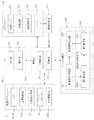
- the blood flow measurement device 1 includes a fundus camera unit 2, an OCT unit 100, and an arithmetic control unit 200.
- the fundus camera unit 2 includes an optical system that is almost the same as that of a conventional fundus camera.
- the OCT unit 100 includes an optical system for acquiring an OCT image of the fundus.
- the arithmetic control unit 200 includes a computer that executes various calculations and controls.
- the fundus camera unit 2 shown in FIG. 1 is provided with an optical system for obtaining a two-dimensional image (fundus image) representing the surface form of the fundus oculi Ef of the eye E to be examined.
- the fundus image includes an observation image and a captured image.
- the observation image is, for example, a monochrome moving image formed at a predetermined frame rate using near infrared light.
- the captured image may be, for example, a color image obtained by flashing visible light, or a monochrome still image using near infrared light or visible light as illumination light.
- the fundus camera unit 2 may be configured to be able to acquire images other than these, for example, a fluorescein fluorescent image, an indocyanine green fluorescent image, a spontaneous fluorescent image, and the like.
- the fundus camera unit 2 is provided with a chin rest and a forehead for supporting the subject's face. Further, the fundus camera unit 2 is provided with an illumination optical system 10 and a photographing optical system 30.
- the illumination optical system 10 irradiates the fundus oculi Ef with illumination light.
- the photographing optical system 30 guides the fundus reflection light of the illumination light to an imaging device (CCD image sensor (sometimes simply referred to as a CCD) 35, 38).
- the imaging optical system 30 guides the measurement light from the OCT unit 100 to the fundus oculi Ef and guides the return light of the measurement light from the fundus oculi Ef to the OCT unit 100.
- the observation light source 11 of the illumination optical system 10 includes, for example, a halogen lamp or an LED (Light Emitting Diode).
- the light (observation illumination light) output from the observation light source 11 is reflected by the reflection mirror 12 having a curved reflection surface, passes through the condensing lens 13, passes through the visible cut filter 14, and is converted into near infrared light. Become. Further, the observation illumination light is once converged in the vicinity of the photographing light source 15, reflected by the mirror 16, and passes through the relay lenses 17 and 18, the diaphragm 19 and the relay lens 20. Then, the observation illumination light is reflected at the peripheral portion (region around the hole portion) of the aperture mirror 21, passes through the dichroic mirror 46, and is refracted by the objective lens 22 to illuminate the fundus oculi Ef.
- the fundus reflection light of the observation illumination light is refracted by the objective lens 22, passes through the dichroic mirror 46, passes through the hole formed in the central region of the perforated mirror 21, passes through the dichroic mirror 55, and is a focusing lens. 31, reflected by the mirror 32, transmitted through the half mirror 40, reflected by the dichroic mirror 33, and imaged on the light receiving surface of the CCD image sensor 35 by the condenser lens 34.
- the CCD image sensor 35 detects fundus reflected light at a predetermined frame rate.
- an image (observation image) based on fundus reflection light detected by the CCD image sensor 35 is displayed.
- an observation image of the anterior segment of the eye E is displayed.
- the imaging light source 15 includes, for example, a xenon lamp or an LED.
- the light (imaging illumination light) output from the imaging light source 15 is applied to the fundus oculi Ef through the same path as the observation illumination light.
- the fundus reflection light of the imaging illumination light is guided to the dichroic mirror 33 through the same path as that of the observation illumination light, passes through the dichroic mirror 33, is reflected by the mirror 36, and is reflected by the condenser lens 37 of the CCD image sensor 38.
- An image is formed on the light receiving surface.
- On the display device 3 an image (captured image) based on fundus reflection light detected by the CCD image sensor 38 is displayed.
- the LCD (Liquid Crystal Display) 39 displays a fixation target and an eyesight measurement index.
- the fixation target is an index for fixing the eye E to be examined, and is used at the time of fundus photographing or OCT. By changing the display position of the fixation target on the screen of the LCD 39, the fixation position of the eye E can be changed.
- a part of the light output from the LCD 39 is reflected by the half mirror 40, reflected by the mirror 32, passes through the focusing lens 31 and the dichroic mirror 55, passes through the hole of the perforated mirror 21, and is dichroic.
- the light passes through the mirror 46, is refracted by the objective lens 22, and is projected onto the fundus oculi Ef.
- the fundus camera unit 2 is provided with an alignment optical system 50 and a focus optical system 60 as in the conventional fundus camera.
- the alignment optical system 50 generates an index (alignment index) for performing alignment (alignment) of the apparatus optical system with respect to the eye E.
- the focus optical system 60 generates an index (split index) for focusing on the fundus oculi Ef.
- the light (alignment light) output from the LED 51 of the alignment optical system 50 is reflected by the dichroic mirror 55 via the apertures 52 and 53 and the relay lens 54, passes through the hole of the aperture mirror 21, and reaches the dichroic mirror 46. And is projected onto the eye E by the objective lens 22.
- the return light of the alignment light is detected by the CCD image sensor 35.
- the light reception image (alignment index image) by the CCD image sensor 35 is displayed together with the observation image.
- the user can perform the alignment while referring to the alignment index image, similarly to the conventional fundus camera.
- the arithmetic control unit 200 can also perform alignment by analyzing the position of the alignment index image and moving the optical system (auto alignment function).
- the reflecting surface of the reflecting rod 67 is obliquely provided on the optical path of the illumination optical system 10.
- the light (focus light) output from the LED 61 of the focus optical system 60 passes through the relay lens 62, is separated into two light beams by the split indicator plate 63, passes through the two-hole aperture 64, and is reflected by the mirror 65, The light is focused on the reflecting surface of the reflecting bar 67 by the condenser lens 66 and reflected. Further, the focus light passes through the relay lens 20, is reflected by the perforated mirror 21, passes through the dichroic mirror 46, is refracted by the objective lens 22, and is projected onto the fundus oculi Ef.
- the return light of the focus light is detected by the CCD image sensor 35.
- the light reception image (split index image) by the CCD image sensor 35 is displayed together with the observation image and the alignment index image.
- the arithmetic control unit 200 can perform focusing by analyzing the position of the split index and moving the focusing lens 31 and the focus optical system 60 in the same manner as in the past (autofocus function). Further, manual focusing may be performed while referring to the position of the split index image.
- the dichroic mirror 46 synthesizes an optical path for OCT (OCT optical path) with an optical path for fundus imaging. That is, the fundus imaging optical path and the OCT optical path are configured coaxially by the dichroic mirror 46 and share the optical path on the eye E side with respect to the dichroic mirror 46.
- the dichroic mirror 46 reflects light in a wavelength band used for OCT and transmits light for fundus photographing.
- a collimator lens unit 40, an optical path length changing unit 41, a galvano scanner 42, a focusing lens 43, a mirror 44, and a relay lens 45 are provided in this order from the OCT unit 100 side.
- the optical path length changing unit 41 is movable in the direction of the arrow shown in FIG. 1, and changes the length of the OCT optical path. This change in the optical path length is used for correcting the optical path length according to the axial length of the eye E or adjusting the interference state.
- the optical path length changing unit 41 includes, for example, a corner cube and a mechanism for moving the corner cube.
- the galvano scanner 42 changes the traveling direction of the measurement light LS passing through the OCT optical path. Thereby, the fundus oculi Ef can be scanned with the measurement light LS.
- the galvano scanner 42 includes, for example, a galvanometer mirror that scans the measurement light LS in the x direction, a galvanometer mirror that scans in the y direction, and a mechanism that drives these independently. Thereby, the measurement light LS can be scanned in an arbitrary direction on the xy plane.
- the OCT unit 100 is provided with an optical system for acquiring an OCT image of the fundus oculi Ef.
- This optical system divides the low-coherence light into reference light and measurement light, and causes the measurement light passing through the fundus Ef and the reference light passing through the reference optical path to interfere with each other as in the conventional spectral domain type OCT apparatus.
- An interference light is generated and a spectral component of the interference light is detected. This detection result (detection signal) is sent to the arithmetic control unit 200.
- a wavelength swept light source is provided instead of a low-coherence light source, and a balanced photodiode is provided instead of a device (spectrometer) for detecting a spectral component.
- the OCT unit 100 may have a known configuration corresponding to the type of OCT.
- the light source unit 101 outputs low coherence light L0 (broadband light).
- the low coherence light L0 includes, for example, a near-infrared wavelength band (approximately 800 nm to 900 nm) and has a temporal coherence length of approximately several tens of micrometers.
- near infrared light having a center wavelength of 1040 to 1060 nm may be used as the low coherence light L0.
- the light source unit 101 includes a super luminescent diode (Super Luminescent Diode: SLD), an LED, and an optical output device such as an SOA (Semiconductor Optical Amplifier).
- SLD Super Luminescent Diode
- LED an LED
- SOA semiconductor Optical Amplifier
- the low coherence light L0 output from the light source unit 101 is guided to the fiber coupler 103 by the optical fiber 102 and is divided into the measurement light LS and the reference light LR.
- the reference light LR is guided by the optical fiber 104 and reaches an optical attenuator (attenuator) 105.
- the optical attenuator 105 changes the amount of the reference light LR guided to the optical fiber 104 under the control of the arithmetic control unit 200 or by manual operation.
- the reference light LR whose light amount has been adjusted by the optical attenuator 105 is guided by the optical fiber 104 and reaches the polarization adjuster (polarization controller) 106.
- the polarization adjuster 106 changes the polarization state of the reference light LR guided through the optical fiber 104.
- the reference light LR whose polarization state is adjusted by the polarization adjuster 106 reaches the fiber coupler 109.
- the measurement light LS generated by the fiber coupler 103 is guided by the optical fiber 107 and converted into a parallel light beam by the collimator lens unit 105. Further, the measurement light LS reaches the dichroic mirror 46 via the optical path length changing unit 41, the galvano scanner 42, the focusing lens 43, the mirror 44, and the relay lens 45. Then, the measurement light LS is reflected by the dichroic mirror 46, is refracted by the objective lens 11, and enters the eye E to be examined. The measurement light LS is reflected and scattered at various depth positions of the fundus oculi Ef.
- the return light (backscattered light, reflected light, fluorescence, etc.) of the measurement light LS from the fundus oculi Ef travels in the same direction as the forward path in the reverse direction and is guided to the fiber coupler 103, and passes through the optical fiber 108 to the fiber coupler. 109 is reached.
- the fiber coupler 109 causes the return light of the measurement light LS to interfere with the reference light LR. Thereby, the interference light LC is generated.
- the interference light LC is guided by the optical fiber 110 and is emitted from the emission end 111. Further, the interference light LC is converted into a parallel light beam by the collimator lens 112, spectrally resolved by the diffraction grating 113, condensed by the condenser lens 114, and projected onto the light receiving surface of the CCD image sensor 115.
- the diffraction grating 118 shown in FIG. 2 is a transmission type, but other types of spectroscopic elements such as a reflection type diffraction grating can also be used.
- the CCD image sensor 115 is a line sensor, for example, and detects each spectral component of the interference light LC and converts it into electric charges.
- the CCD image sensor 115 accumulates this electric charge, generates a detection signal, and sends it to the arithmetic control unit 200.
- another image sensor for example, a CMOS (Complementary Metal Oxide Semiconductor) image sensor may be used.
- CMOS Complementary Metal Oxide Semiconductor
- the arithmetic control unit 200 analyzes the detection signal input from the CCD image sensor 115 and forms an OCT image of the fundus oculi Ef.
- the arithmetic processing for that is the same as the conventional spectral domain OCT.
- the arithmetic control unit 200 controls the fundus camera unit 2, the display device 3, and the OCT unit 100.
- the fundus camera unit 2 is controlled by controlling the operation of the observation light source 11, the imaging light source 15, the LCD 39, the galvano scanner 42, and the LEDs 51 and 61, the focusing lenses 31 and 43, the optical path length changing unit 41, and the focus optical system. 60, as well as the movement control of each of the reflecting bars 67.
- Control of the OCT unit 100 includes operation control of the light source unit 101, the optical attenuator 105, the polarization adjuster 106, and the CCD image sensor 120.
- the arithmetic control unit 200 includes a processor, RAM, ROM, hard disk drive, communication interface, and the like.
- the arithmetic control unit 200 may include an operation device (input device) such as a keyboard and a mouse, and a display device such as an LCD.
- operation device input device
- display device such as an LCD.
- processor means, for example, CPU (Central Processing Unit), GPU (Graphics Processing Unit), ASIC (Application Specific Integrated Circuit), programmable logic device (for example, SPLD (SimpleDLD). (Complex Programmable Logic Device), FPGA (Field Programmable Gate Array)) and the like.
- the arithmetic control unit 200 implements the functions according to the embodiment by reading and executing a program stored in a storage circuit or a storage device, for example.
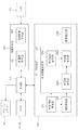
- Control system The configuration of the control system of the blood flow measurement device 1 will be described with reference to FIGS. 3 and 4.
- the control unit 210 includes, for example, the aforementioned processor, RAM, ROM, hard disk drive, communication interface, and the like.
- the control unit 210 is provided with a main control unit 211 and a storage unit 212.
- the storage unit 212 stores various data and computer programs.
- the main control unit 211 performs various controls. For example, as shown in FIG. 3, the main control unit 211 controls the CCDs 35 and 38, the focus driving unit 31A, the optical path length changing unit 41, the galvano scanner 42, and the focus driving unit 43A of the fundus camera unit 2. . Further, the main control unit 211 controls the light source unit 101, the optical attenuator 105, the polarization adjuster 106, and the CCD 115 of the OCT unit 100.
- the focusing drive unit 31A moves the focusing lens 31 in the optical axis direction. Thereby, the focus position of the photographic optical system 30 changes.
- the focusing drive unit 43A moves the focusing lens 43 in the optical axis direction.
- the focus position of the measurement light LS OCCT measurement focus position
- the main control unit 211 can move an optical system provided in the fundus camera unit 2 three-dimensionally by controlling an optical system driving unit (not shown). This movement control of the optical system is used in alignment and tracking.
- the tracking is a process of moving the apparatus optical system in accordance with the eye movement of the eye E. Prior to tracking, alignment and focus adjustment are performed. Tracking is a function that maintains the state of alignment and focus by causing the position of the apparatus optical system to follow the eye movement.
- the image forming unit 220 forms tomographic image data and phase image data of the fundus oculi Ef based on the detection signal from the CCD image sensor 115.
- the image forming unit 220 includes a processor. In this specification, “image data” and “image” based thereon may be identified.
- the image forming unit 220 includes a tomographic image forming unit 221 and a phase image forming unit 222.
- first scanning and second scanning two types of scanning are performed on the fundus oculi Ef.
- first scan four or more cross sections (auxiliary cross sections) intersecting the target blood vessel of the fundus oculi Ef are scanned with the measurement light LS.
- second scanning the cross section of interest that intersects the blood vessel of interest is repeatedly scanned with the measurement light LS.
- the auxiliary cross section in which the first scan is performed is arranged in the vicinity of the target cross section.
- the data acquired by the first scan is used to obtain the direction (inclination, inclination angle) of the target blood vessel in the target cross section.
- the second scan is Doppler measurement using OCT.
- the target cross sections of the first scan and the second scan are oriented so as to be orthogonal to the traveling direction of the blood vessel of interest on the xy plane.
- the fundus oculi image D of FIG. 5 in this embodiment, for example, in the vicinity of the optic disc Da, four auxiliary sections C11 to C14 in which the first scan is performed, and a section of interest C2 in which the second scan is performed. Is set so as to intersect the target blood vessel Db.
- auxiliary cross sections C11 to C14 Two of the four auxiliary cross sections C11 to C14 (for example, auxiliary cross sections C11 and C12) are located upstream of the target blood vessel Db with respect to the target cross section C2, and the other two (for example, auxiliary cross sections C13 and C14) are downstream.
- the auxiliary cross sections C12 and C13 are disposed adjacent to the target cross section C2.
- the auxiliary cross section C11 is disposed on the opposite side of the target cross section C2 with respect to the auxiliary cross section C12
- the auxiliary cross section C14 is disposed on the opposite side of the target cross section C2 with respect to the auxiliary cross section C14. That is, the auxiliary cross section C11 is arranged on the most upstream side, and the auxiliary cross section C14 is arranged on the most downstream side.
- the distance between the auxiliary cross sections C12 and C13 with respect to the target cross section C2 is set in advance. Further, the distance between the auxiliary cross section C11 and the auxiliary cross section C12 and the distance between the auxiliary cross section C13 and the auxiliary cross section C14 are also set in advance.
- the five cross sections including the auxiliary cross sections C11 to C14 and the target cross section C2 are arranged at equal intervals. The interval between these five cross sections is set in the range of 50 ⁇ m to 100 ⁇ m, for example. In this case, the distance between the auxiliary cross sections C11 and C14 located at both ends is in the range of 200 ⁇ m to 400 ⁇ m.
- the number of auxiliary cross sections is not limited to four, but may be five or more.
- the interval between N + 1 (N ⁇ 4) auxiliary cross sections and N + 1 cross sections including the target cross section (cross section interval), and the distance between the cross sections located at both ends (cross section full width) of these cross sections are arbitrary. Is set.
- the cross-sectional spacing affects errors due to blood vessel meandering. The smaller the cross-sectional interval is set, the smaller the error becomes.
- the full width of the cross section affects the accuracy and accuracy of the calculation of the inclination angle of the blood vessel of interest. The accuracy and accuracy of calculation increase as the overall cross-sectional width is set larger.
- the target cross section can be arranged at the center of an odd number of cross sections including the target cross section.
- the number of auxiliary sections can be set arbitrarily. Increasing the number of auxiliary sections can reduce the error due to the meandering of the blood vessel, but the scanning time becomes longer, so the influence of the error due to the movement of the eye E increases. According to this example, it is possible to set the conditions for the first scan while individually or comprehensively considering the above factors.
- the second scan is preferably performed over at least one cardiac cycle of the patient's heart. Thereby, blood flow information in all time phases of the heart is obtained.
- the execution time of the second scan may be a predetermined time set in advance, or may be a time set for each patient or for each examination.
- the tomographic image forming unit 221 forms a tomographic image corresponding to each of the auxiliary cross sections C11 to C14 based on the detection result of the interference light LC obtained by the first scanning with respect to the four auxiliary cross sections C11 to C14.
- the auxiliary sections C11 to C14 can be scanned once, and a tomographic image can be formed for each of the auxiliary sections C11 to C14.
- the auxiliary sections C11 to C14 may be scanned a plurality of times, and a plurality of tomographic images may be formed for the auxiliary sections C11 to C14.
- the tomographic image forming unit 221 forms a tomographic image group representing a time-series change in the form of the target cross section C2 based on the detection result of the interference light LC obtained by the second scan with respect to the target cross section C2. This process will be described in more detail.
- the target section C2 is repeatedly scanned as described above.
- Detection signals are sequentially input from the CCD 115 of the OCT unit 100 to the tomographic image forming unit 221 in accordance with the second scan.
- the tomographic image forming unit 221 forms one tomographic image of the cross section of interest C2 based on a detection signal group corresponding to one scan of the cross section of interest C2.
- the tomographic image forming unit 221 forms a series of tomographic images along a time series by repeating this process as many times as the second scanning is repeated.
- these tomographic images may be divided into a plurality of groups, and the tomographic images of each group may be averaged to improve the image quality.
- the process executed by the tomographic image forming unit 221 includes noise removal (noise reduction), filter processing, FFT (Fast Fourier Transform), and the like, as in the conventional spectral domain OCT.
- noise removal noise reduction
- filter processing filter processing
- FFT Fast Fourier Transform
- the tomographic image forming unit 221 executes a known process according to the type.
- phase image forming unit 222 forms a phase image representing the time-series change of the phase difference in the target cross section C2 based on the detection result of the interference light LS obtained by the second scanning with respect to the target cross section C2.
- the data used for this processing is the same as the data used by the tomographic image forming unit 221 to form a tomographic image of the cross section of interest C2. Therefore, the tomographic image and the phase image of the cross section of interest C2 can be aligned. That is, it is possible to naturally associate the pixels of the tomographic image of the cross section of interest C2 with the pixels of the phase image.
- phase image in this example is obtained by calculating the phase difference between adjacent A-line complex signals (signals corresponding to adjacent scanning points).
- the phase image of this example is formed based on the time-series change of the pixel value (luminance value) of each pixel of the tomographic image of the target cross section C2.
- the phase image forming unit 222 considers a graph of a time-series change in luminance value.
- the phase difference ⁇ is defined as the phase difference ⁇ (t1) at the time point t1 (more generally, any time point between the two time points t1 and t2).
- the phase image represents the value of the phase difference at each time point of each pixel as an image.
- This imaging process can be realized, for example, by expressing the value of the phase difference with the display color or brightness.
- a color indicating that the phase has increased along the time series for example, red
- a color indicating that the phase has decreased for example, blue
- the magnitude of the phase change amount can be expressed by the darkness of the display color.
- the time-series change of the phase difference can be obtained by ensuring the phase correlation by sufficiently reducing the time interval ⁇ t.
- oversampling in which the time interval ⁇ t is set to a value less than the time corresponding to the resolution of the tomographic image in the scanning of the measurement light LS is executed.
- the data processing unit 230 executes various data processing.
- the data processing unit 230 performs image processing and analysis processing on the image formed by the image forming unit 220. Specific examples thereof include various correction processes such as luminance correction and dispersion correction. Further, the data processing unit 230 performs image processing and analysis processing on an image (fundus image, anterior eye image, etc.) obtained by the fundus camera unit 2.
- the data processing unit 230 includes a blood vessel region specifying unit 231, an inclination angle calculating unit 232, and a blood flow information generating unit 233.
- the tilt angle calculation unit 232 includes a first calculation unit 232a and a second calculation unit 232b.
- the blood flow information generation unit 233 is provided with a blood flow velocity calculation unit 2331, a blood vessel diameter calculation unit 2332, and a blood flow rate calculation unit 2333. Further, the data processing unit 230 has a cross-section setting unit 234.
- the blood vessel region specifying unit 231 specifies a blood vessel region corresponding to the target blood vessel Db in the tomographic image formed by the tomographic image forming unit 221. Further, the blood vessel region specifying unit 231 specifies a blood vessel region corresponding to the target blood vessel Db in the phase image formed by the phase image forming unit 222.
- the blood vessel region is specified by analyzing the pixel value of each image (for example, threshold processing).
- the blood vessel region of the phase image may be specified with reference to the blood vessel region of the tomographic image of the cross section of interest C2.
- the inclination angle calculation unit 232 calculates the inclination angle of the target blood vessel Db in the target cross section C2 based on the data acquired by the first scan. At this time, it is possible to further use data obtained by the second scanning.
- the inclination angle calculation unit 232 calculates, for example, the inclination angle of the target blood vessel Db in the target cross section C2 based on the cross-sectional interval and the blood vessel region specifying result. In the example shown in FIG.
- the cross-sectional interval includes a distance between the auxiliary cross section C11 and the auxiliary cross section C12, and a distance between the auxiliary cross section C13 and the auxiliary cross section C14, and further includes the attention cross section C2 and the auxiliary cross section C12. And a distance between the target cross section C2 and the auxiliary cross section C13.
- the tilt angle calculation unit 232 includes the first calculation unit 232a and the second calculation unit 232b.
- the first calculation unit 232a analyzes the first data group including two or more pieces of data among four or more data (tomographic images) corresponding to four or more auxiliary sections acquired by the first scan. The first inclination angle of the blood vessel is obtained. Further, the first calculation unit 232a obtains the second inclination angle of the blood vessel of interest by analyzing the second data group including two or more data including one or more data not included in the first data group.
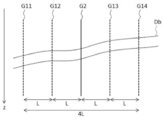
- the outline of the tomographic image group formed by such a series of scanning is shown in FIG.
- Four symbols G11 to G14 represent tomographic images obtained by a series of scans on the four auxiliary sections C11 to C14, respectively.
- Reference symbol G2 is a tomographic image representing the cross section of interest C2 obtained by the second scan executed together with the first scan.
- a cross section of the blood vessel Db of interest is depicted in each of the tomographic images G11 to G14 and G2.
- the z coordinate axis is directed downward in the drawing, and this substantially coincides with the irradiation direction of the measurement light LS (the optical axis of the optical path of the measurement light LS).
- L be the interval between adjacent tomographic images (cross sections).
- two tomographic images G11 and G12 auxiliary cross sections C11 and C12
- two tomographic images G13 and G14 are arranged on the other side. Since (auxiliary sections C13 and C14) are arranged, the distance (cross section full width) between the tomographic images G11 and G14 at both ends (auxiliary sections C11 and C14 at both ends) is 4L.
- the cross-sectional interval L may be an arbitrary value within the range of 50 ⁇ m to 100 ⁇ m
- the total cross-sectional width 4L may be an arbitrary value within the range of 200 ⁇ m to 400 ⁇ m.
- the two outer tomographic images G11 and G14 can be used as the first data group, and the two inner tomographic images G12 and G13 can be used as the second data group.
- the first calculation unit 232a obtains the first inclination angle of the target blood vessel Db by analyzing the tomographic images G11 and G14, and analyzes the tomographic images G12 and G13 to obtain the second inclination of the target blood vessel Db. Find the angle. That is, in this example, the four tomographic images G11 to G14 are divided into two mutually exclusive groups, and the value of the inclination angle of the target blood vessel Db is calculated based on each group. In another example, four or more data acquired by the first scan may be divided into three or more groups, or may be divided into two or more groups partially overlapping.
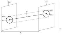
- FIG. 7 shows two outer tomographic images G11 and G14.
- a reference symbol V11 indicates a blood vessel region in the tomographic image G11 specified by the blood vessel region specifying unit 231.
- reference sign V14 indicates a blood vessel region in the tomographic image G14 specified by the blood vessel region specifying unit 231.
- These blood vessel regions V11 and V14 correspond to the cross section of the blood vessel Db of interest.
- the distance between these tomographic images G11 and G14 is a cross-sectional total width of 4L.
- the first calculation unit 232a calculates the first inclination angle of the target blood vessel Db based on the positional relationship between the two blood vessel regions V11 and V14.
- the positional relationship between the two blood vessel regions V11 and V14 is obtained, for example, by connecting the two blood vessel regions V11 and V14.
- the first calculation unit 232a identifies the feature points W11 and W14 of the two blood vessel regions V11 and V14, respectively, and obtains a line segment K1 connecting these feature points W11 and W14.
- the feature points W11 and W14 include a center, a center of gravity, an uppermost portion (a position where the z coordinate value is minimum), a lowermost portion (a position where the z coordinate value is maximum), and the like.
- two feature points are connected by a line segment (straight line), but the present invention is not limited to this.
- three or more feature points can be connected by an approximate curve (spline curve, Bezier curve, etc.) or a broken line.
- the first calculator 232a calculates the first inclination angle of the target blood vessel Db based on the line segment K1 connecting these feature points W11 and W14.
- the first tilt angle is defined as, for example, an angle formed by the line segment K1 with respect to the z coordinate axis, or an angle formed by the line segment K1 with respect to a plane (xy plane) orthogonal to the z coordinate axis.
- the tilt angle at an arbitrary position on the approximate curve for example, the tilt angle at the target cross section C2 can be calculated.
- a statistical value (average value, median value, mode value, etc.) of the inclination angle of two or more line segments forming the polygonal line is calculated. be able to.
- the cross-sectional interval L is used for embedding the tomographic images G11 and G14 and the like in the xyz coordinate system in the process of obtaining line segments and approximate curves.
- the inclination angle of the target blood vessel Db is obtained based on the blood vessel region, but it is also possible to estimate the inclination angle based on a predetermined region in the tomographic image.
- a predetermined tissue such as an inner boundary membrane (ILM)
- ILM inner boundary membrane
- the process of calculating the second inclination angle of the target blood vessel Db based on the two inner tomographic images G12 and G13 is performed in the same manner as described above.
- the distance between these tomographic images G12 and G13 is 2L, which is narrower than the full width of the cross section.
- the intermediate position between the tomographic image G11 and the tomographic image G14 and the intermediate position between the tomographic image G12 and the tomographic image G13 are both the cross section of interest C2.
- the second calculation unit 232b obtains the inclination angle of the attention blood vessel Db in the attention section C2 based on the first inclination angle and the second inclination angle obtained by the first calculation part 232a.
- FIG. 8 shows an example of the first tilt angle and the second tilt angle.
- Reference numerals W11 to W14 denote feature points in the tomographic images G11 to G14 shown in FIG.
- Reference sign K1 indicates a line segment connecting the two outer feature points W11 and W14
- reference sign K2 indicates a line segment connecting the two inner feature points W12 and W13.
- the distance between the two outer feature points W11 and W14 is 4L
- the distance between the two inner feature points W12 and W13 is 2L.
- ⁇ z1 indicates the displacement in the z direction between the two outer feature points W11 and W14 (difference in z coordinate value)
- ⁇ z2 indicates the z direction between the two inner feature points W12 and W13. Displacement (difference in z-coordinate values) is indicated.
- the second calculation unit 232b sets an allowable range based on the second inclination angle ⁇ 2.
- This allowable range is set based on, for example, the error ⁇ set in advance based on the total cross section width 4L, the cross section interval L, and the number of cross sections, and the second inclination angle ⁇ 2.
- the second calculation unit 232b determines whether the first inclination angle ⁇ 1 satisfies the following relationship: ⁇ 2- ⁇ ⁇ 1 ⁇ 2 + ⁇ . That is, the second calculator 232b determines whether or not the first inclination angle ⁇ 1 is included in the range of the error ⁇ with respect to the second inclination angle ⁇ 2.
- the first inclination angle ⁇ 1 When the first inclination angle ⁇ 1 is included in the allowable range, the first inclination angle ⁇ 1 is adopted as the inclination angle ⁇ of the target blood vessel Db in the target cross section C2. On the other hand, when the first tilt angle ⁇ 1 is not included in the allowable range, the subsequent processing can be executed while ignoring the first tilt angle ⁇ 1. Moreover, you may make it employ
- the second calculator 232b calculates statistical values of the first inclination angle ⁇ 1 and the second inclination angle ⁇ 2.
- This statistical value is, for example, an average value (simple average, weighted average, etc.).
- the calculated statistical value is adopted as the inclination angle ⁇ of the target blood vessel Db in the target cross section C2.
- the blood flow information generation unit 233 generates blood flow information of the eye E based on the data acquired by scanning the cross section of interest by the second scan and the inclination angle ⁇ obtained by the second calculation unit 232b. . More specifically, the blood flow information generation unit 233 focuses attention based on the phase image acquired by Doppler OCT and the inclination angle ⁇ of the attention blood vessel Db in the attention section C2 calculated by the second calculation unit 232b. Blood flow information relating to the blood vessel Db is generated. As described above, the blood flow information generation unit 233 is provided with the blood flow velocity calculation unit 2331, the blood vessel diameter calculation unit 2332, and the blood flow rate calculation unit 2333.
- the blood flow velocity calculation unit 2331 calculates the blood flow velocity in the target section C2 of the blood flowing in the target blood vessel Db based on the time-series change of the phase difference obtained as the phase image.
- This calculation target may be a blood flow velocity at a certain point in time, or a time-series change (blood flow velocity change information) of this blood flow velocity.
- the time range in the latter is the entire time or arbitrary part of the time when the target cross section C2 is scanned.
- the blood flow velocity calculator 2331 can calculate a statistical value of the blood flow velocity in the time range.
- the statistical values include an average value, standard deviation, variance, median value, maximum value, minimum value, maximum value, minimum value, and the like. It is also possible to create a histogram for blood flow velocity values.
- the blood flow velocity calculation unit 2331 calculates the blood flow velocity using the Doppler OCT method as described above. At this time, the inclination angle ⁇ of the target blood vessel Db in the target cross section C2 calculated by the inclination angle calculation unit 232 is taken into consideration. Specifically, the tilt angle calculation unit 232 uses the following formula.
- ⁇ f represents the Doppler shift received by the scattered light of the measurement light LS
- n represents the refractive index of the medium (blood)
- v represents the flow velocity (blood flow velocity) of the medium
- ⁇ represents an angle formed by the incident direction of the measurement light LS and the flow direction (tilt angle) of the medium
- ⁇ represents the center wavelength of the measurement light LS.
- n and ⁇ are known, ⁇ f is obtained from a time-series change in phase difference, and ⁇ is an inclination angle or obtained from an inclination angle.
- the blood vessel diameter calculator 2332 calculates the diameter of the target blood vessel Db in the target cross section C2. Examples of this calculation method include a first calculation method using a fundus image and a second calculation method using a tomographic image.
- the fundus image obtained thereby may be an observation image (frame) or a captured image.
- the captured image is a color image
- an image constituting the image for example, a red free image
- the blood vessel diameter calculation unit 2332 is based on various factors that determine the relationship between the scale on the image and the scale in the real space, such as information on the imaging angle of view (imaging magnification), working distance, and eyeball optical system.
- This scale represents the length in real space.
- the blood vessel diameter calculation unit 2332 calculates the diameter of the target blood vessel Db in the target cross section C2, that is, the diameter of this blood vessel region, based on this scale and the pixels included in the blood vessel region in the tomographic image G2. As a specific example, the blood vessel diameter calculation unit 2332 obtains the maximum value and the average value of the diameters of the blood vessel region in various directions. Further, the blood vessel region 235 can approximate the outline of the blood vessel region in a circle or an ellipse, and obtain the diameter of the circle or the ellipse. If the blood vessel diameter is determined, the area of the blood vessel region can be (substantially) determined, so that the area may be calculated instead of obtaining the blood vessel diameter.
- the second calculation method will be described.
- a tomographic image of the fundus oculi Ef at the cross section of interest C2 is used.
- This tomographic image may be a tomographic image based on the second scanning, or may be acquired separately.
- the scale in this tomographic image is determined according to the scanning mode of the measurement light LS.
- the length of the cross section of interest C2 is various factors that determine the relationship between the scale on the image and the scale in real space, such as working distance and information on the eyeball optical system. To be determined.
- the blood vessel diameter calculation unit 2332 obtains an interval between adjacent pixels based on this length, and calculates the diameter of the target blood vessel Db in the target cross section C2 in the same manner as in the first calculation method.
- the blood flow rate calculation unit 2333 calculates the flow rate of blood flowing in the target blood vessel Db based on the blood flow velocity calculation result and the blood vessel diameter calculation result. An example of this process will be described below.
- the blood flow in the blood vessel is a Hagen-Poiseuille flow.
- the blood flow rate Q is expressed by the following equation.
- the blood flow rate calculation unit 2333 substitutes the calculation result w of the blood vessel diameter by the blood vessel diameter calculation unit 2332 and the maximum value Vm based on the calculation result of the blood flow velocity by the blood flow velocity calculation unit 2331 into Expression (2).
- the blood flow rate Q is calculated.
- the main control unit 211 causes the display unit 241 to display a fundus image.
- This fundus image may be an observation image or a captured image. Further, the fundus image may be an image constituting a captured image.
- the user operates the operation unit 242 to specify the attention cross section C2 in the displayed fundus image.
- the cross section setting unit 234 sets four (or more) auxiliary cross sections C11 to C14 to which the first scan is applied, based on the designated target cross section C2 and the fundus image. As described above, the target cross section C2 is specified so as to cross the desired target blood vessel Db.
- the operation of designating the cross section of interest C2 as a fundus image is performed using, for example, a pointing device.
- the display unit 241 is a touch panel
- the user designates the attention cross section C2 by touching a desired position of the displayed fundus image.
- the parameters (direction, length, etc.) of the target cross section C2 are set manually or automatically.
- a predetermined interface for setting parameters can be used.
- This interface may be hardware such as a switch or software such as a graphical user interface (GUI).
- GUI graphical user interface
- the cross-section setting unit 234 sets parameters based on the position designated by the user for the fundus image.
- a predetermined value may be applied, or the designated position and the position of a blood vessel in the vicinity thereof may be considered.
- the former value is designated based on, for example, a general distance between a predetermined blood vessel of interest and a blood vessel in the vicinity thereof. This distance information can be generated based on clinical data. The same applies to the latter case.
- a predetermined orientation may be applied, or the orientation of the attention blood vessel Db may be considered.
- information indicating the orientation of each predetermined target blood vessel at each position is generated in advance and referred to. This information can be generated based on clinical data.
- the traveling direction of the target blood vessel Db at the designated position is obtained and set based on the traveling direction. The process for obtaining the traveling direction is performed, for example, through a thinning process of the target blood vessel Db.
- it is desirable that the orientation of the cross section of interest C2 is set to be orthogonal to the traveling direction on the xy plane.
- the cross section setting unit 234 sets the auxiliary cross sections C11 to C14 at positions separated from the target cross section C2 by a predetermined distance. This distance corresponds to the aforementioned cross-sectional interval (L) and full cross-sectional width (4L). Further, the lengths and / or orientations of the auxiliary cross sections C11 to C14 are set in the same manner as in the case of the target cross section C2.
- the data processing unit 230 that functions as described above includes, for example, a processor, a RAM, a ROM, a hard disk drive, a circuit board, and the like.
- a storage device such as a hard disk drive stores in advance a computer program that causes the processor to execute the above functions.
- the user interface 240 includes a display unit 241 and an operation unit 242.
- the display unit 241 includes the display device of the arithmetic control unit 200 and the display device 3.
- the operation unit 242 includes an operation device of the arithmetic control unit 200.
- the user interface 240 may include a device having a display function and an operation function, such as a touch panel.
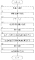
- FIG. 9 illustrates an example of the operation of the blood flow measurement device 1.
- a patient for blood flow measurement is selected. Selection of a patient is performed by inputting a patient ID, for example.
- the user designates a position for photographing the eye E by adjusting the position of the apparatus optical system.
- alignment of the apparatus optical system with respect to the eye E is performed.
- the alignment is performed using, for example, an alignment index.
- two or more anterior eye cameras described in Japanese Patent Application Laid-Open No. 2013-248376 by the present applicant are provided, two or more obtained by photographing the anterior eye part substantially simultaneously from different directions Alignment can be performed based on the image. In this step, focus adjustment or the like may be further performed.
- a position where blood flow measurement is performed (particularly the cross section of interest C2) is designated.
- a process for determining whether or not the cross section designated by the user is appropriate can be executed.
- This suitability determination includes, for example, a process of calculating the inclination angle of the blood vessel in the cross section based on an image obtained by OCT scanning the cross section and the vicinity thereof, and whether or not the inclination angle is included in an allowable range. The process of determining whether or not.
- this cross section is adopted as a blood flow measurement target (attention cross section C2).
- the section setting unit 234 sets four (or more) auxiliary sections C11 to C14 to be subjected to the first scanning.
- the blood flow measurement device 1 executes an OCT scan of the auxiliary cross sections C11 to C14 set by the cross section setting unit 234 in step S4 (first scan).
- the OCT scan in the first scan is executed in the following order, for example.
- the four auxiliary sections C11 to C14 are OCT scanned in the order of “C11 ⁇ C14 ⁇ C12 ⁇ C13” (a series of scans described above).
- scanning of the auxiliary cross sections C11 and C14 corresponding to the first data group is continuously performed, and the second data group (the inner two The auxiliary cross sections C12 and C13 corresponding to the two tomographic images G12 and G13) are continuously scanned.
- one tomographic image corresponding to each of the four auxiliary sections C11 to C14 is formed.
- the series of scans “C11 ⁇ C14 ⁇ C12 ⁇ C13” in the first example are repeatedly executed. That is, in the second example, the OCT scan is performed on the four auxiliary sections C11 to C14 in the order of “C11 ⁇ C14 ⁇ C12 ⁇ C13 ⁇ C11 ⁇ C14 ⁇ C12 ⁇ C13 ⁇ C11 ⁇ .
- the auxiliary cross sections C11 and C14 corresponding to the first data group are continuously scanned, and While continuously scanning the auxiliary sections C12 and C13 corresponding to the second data group (inner two tomographic images G12 and G13), the scanning of the auxiliary sections C11 and C14 corresponding to the first data group is further performed.
- the scanning of the auxiliary cross sections C12 and C13 corresponding to the second data group is executed alternately.
- N pieces of tomographic images corresponding to the four auxiliary sections C11 to C14 are formed (N represents the number of repetitions of a series of scans).
- two data groups are formed from the data acquired by the first scan.
- three or more data groups can be formed from the data acquired by the first scan.
- the auxiliary cross-section group corresponding to the first data group is continuously scanned, and the second data
- the scanning of the auxiliary cross-sectional group corresponding to the group can be continuously executed, and the scanning of the auxiliary cross-sectional group corresponding to the third data group can be continuously executed.
- the scanning of the auxiliary sectional group corresponding to the first data group, the scanning of the scanning of the auxiliary sectional group corresponding to the second data group, and the auxiliary sectional group corresponding to the third data group can be performed cyclically.
- “alternately executing” includes such “cyclical execution”.
- the first calculator 232a determines the first inclination angle ⁇ 1 of the blood vessel Db of interest by analyzing the first data group acquired in step S5. Furthermore, the first calculator 232a obtains the second inclination angle ⁇ 2 of the blood vessel Db of interest by analyzing the second data group.
- the first calculation unit 232a calculates the first inclination angle ⁇ 1 based on the two outer tomographic images G11 and G14, and the two inner tomographic images G12. And the second inclination angle ⁇ 2 is calculated based on G13 (see FIG. 8).
- a plurality of inclination angles of the target blood vessel Db are based on a total of 4N tomographic images formed by N for the four auxiliary sections C11 to C14. Is calculated.
- a combination of 4N tomographic images for obtaining the plurality of values is arbitrary. Specific examples thereof will be described later.
- Step S7 The inclination angle ⁇ at the cross section of interest is calculated
- the second calculator 232b obtains the inclination angle ⁇ of the blood vessel Db of interest in the cross section of interest C2 based on the first inclination angle ⁇ 1 and the second inclination angle ⁇ 2 obtained in step S6. Steps S6 and S7 may be executed after the second scan in step S8.
- the blood flow measurement device 1 executes repetitive OCT scans of the target cross section C2 designated in step S4 (second scan).
- the phase image forming unit 222 forms a phase image representing a time-series change of the phase difference in the cross section of interest C2 based on the data acquired by the second scan.
- the tomographic image forming unit 221 forms a tomographic image G2 of the target cross section C2 based on the data.
- the data processing unit 230 (blood vessel region specifying unit 231, blood vessel diameter calculating unit 2332, etc.) obtains the diameter of the target blood vessel Db in the target cross section C2.
- the blood flow velocity calculation unit 2331 calculates the blood flow velocity in the cross section of interest C2 based on the inclination angle ⁇ calculated in step S7 and the phase image acquired in step S8. Furthermore, the blood flow rate calculation unit 2333 calculates the flow rate of blood flowing in the target blood vessel Db based on the calculation result of the blood flow velocity and the calculation result of the blood vessel diameter obtained in step S8.
- the main control unit 211 causes the display unit 241 to display blood flow information including a blood flow velocity calculation result, a blood flow calculation result, and the like. Further, the main control unit 211 stores blood flow information in the storage unit 212 in association with the patient ID input in step S1. This is the end of the process related to blood flow measurement in this example.
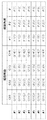
- FIG. 10 shows an example of a combination mode of these 16 tomographic images for calculating the inclination angle of the target blood vessel Db.
- the combination mode shown in FIG. 10 includes seven combinations (# 1, # 2,..., # 7).
- the first combination # 1 includes four tomographic images G11 (1), G12 (1), G13 (1), and G14 (1) obtained in the first series of scans.
- the first calculator 232a calculates the first tilt angle ⁇ 1 (1) based on the tomographic images G11 (1) and G14 (1), and the second tilt angle ⁇ 2 based on the tomographic images G12 (1) and G13 (1). (1) is calculated. Further, the second calculation unit 232b obtains the inclination angle ⁇ (1) of the blood vessel Db of interest in the cross section C2 based on the first inclination angle ⁇ 1 (1) and the second inclination angle ⁇ 2 (1).
- the second combination # 2 includes two tomographic images G11 (2) and G12 (2) obtained by the second series of scans and two tomographic images G13 obtained by the first series of scans. (1) and G14 (1).
- the first calculator 232a calculates the first tilt angle ⁇ 1 (2) based on the tomographic images G11 (2) and G14 (1), and the second tilt angle ⁇ 2 based on the tomographic images G12 (2) and G13 (1). (2) is calculated. Further, the second calculation unit 232b obtains the inclination angle ⁇ (2) of the target blood vessel Db in the target cross section C2 based on the first inclination angle ⁇ 1 (2) and the second inclination angle ⁇ 2 (2).
- the second calculation unit 232b calculates the final result ⁇ of the inclination angle of the target blood vessel Db in the target section C2 based on the seven inclination angles ⁇ (1) to ⁇ (7) acquired in this way.
- This processing may include, for example, processing for calculating statistical values (simple average, addition average, median, mode, etc.) of the seven inclination angles ⁇ (1) to ⁇ (7).
- n n0 in which the difference between the first inclination angle ⁇ 1 (n) and the second inclination angle ⁇ 2 (n) is minimum is specified, and the first inclination angle ⁇ 1 (n0) and the second inclination angle ⁇ 2 (n0).
- the embodiment is a blood flow measurement device that generates blood flow information based on data obtained by repeatedly scanning a cross section of interest (C2) intersecting with a blood vessel of the fundus (attention blood vessel Db) using OCT,
- a data acquisition unit, a first calculation unit, a second calculation unit, and a blood flow information generation unit are provided.
- the data acquisition unit acquires data (tomographic images G11 to G14 and the like) by scanning four or more cross sections (auxiliary cross sections C11 to C14 and the like) intersecting the blood vessel using OCT.
- the first calculation unit analyzes a first data group (tomographic images G11 and G14, etc.) composed of two or more of these four or more data (tomographic images G11 to G14, etc.), thereby obtaining a first blood vessel.
- An inclination angle ( ⁇ 1) is obtained. Further, the first calculation unit analyzes the second data group (tomographic images G12 and G13, etc.) composed of two or more data including one or more data that is not included in the first data group, thereby performing the second inclination of the blood vessel. An angle ( ⁇ 2) is obtained. The second calculation unit obtains the inclination angle ( ⁇ ) of the blood vessel in the cross section of interest based on the first inclination angle and the second inclination angle obtained by the first calculation unit. The blood flow information generation unit generates blood flow information based on data (a phase image or the like) obtained by repeatedly scanning the cross section of interest and the inclination angle obtained by the second calculation unit.
- the data acquisition unit includes an optical system for OCT and an image forming unit 220
- the first calculation unit includes a first calculation unit 232a
- the second calculation unit is a second calculation unit.
- the blood flow information generation unit includes at least a part of the blood flow information generation unit 233.
- the combination of data obtained by OCT scan of four or more auxiliary cross sections is changed, and the inclination angle of the target blood vessel is estimated twice or more, and based on these estimated values,
- the inclination angle of the blood vessel of interest in the cross section of interest for Doppler OCT can be determined.
- the distance (cross section full width) between the auxiliary cross sections located at both ends among the four or more auxiliary cross sections is set wider than the conventional one so as to ensure the accuracy and accuracy of the calculation. For example, it can be set to 400 ⁇ m with respect to the conventional 200 ⁇ m.
- intervals cross-sectional intervals
- the number of auxiliary cross sections can be arbitrarily set. Therefore, it is possible to optimize the setting of the auxiliary cross section for estimating the direction of the blood vessel.
- the first data group may include one or both of the auxiliary cross sections located at both ends among the four or more auxiliary cross sections.
- the first data group includes auxiliary cross sections C11 and C14 positioned at both ends of the four auxiliary cross sections C11 to C14.
- the first data group may be configured to include only one of the auxiliary cross sections C11 and C14.
- the first data group is set such that the distance between two cross sections located at both ends of the first data group is different from the distance between two cross sections located at both ends of the second data group.
- the second data group can be configured.
- the first data group includes auxiliary sections C11 and C14 that are separated by a distance of 4L
- the second data group includes auxiliary sections C12 and C13 that are separated by a distance of 2L.
- the data acquisition unit continuously performs scanning of two or more auxiliary cross sections corresponding to the first data group, and continuously performs scanning of two or more auxiliary cross sections corresponding to the second data group. Can be executed. Thereby, the time interval between two or more OCT scans for collecting two or more data included in the first data group can be shortened, and errors due to the movement of the eye to be examined during the period can be reduced. .
- the data acquisition unit can alternately execute scanning of two or more auxiliary sections corresponding to the first data group and scanning of two or more auxiliary sections corresponding to the second data group.
- a plurality of samples can be acquired for each auxiliary cross section, and an error in calculating the tilt angle can be reduced.
- the present invention includes a case where scanning of three or more auxiliary cross-sectional groups corresponding to three or more data groups is cyclically executed.
- Blood Flow Measuring Device 100 OCT Unit 220 Image Forming Unit 230 Data Processing Unit 232 Inclination Angle Calculation Unit 232a First Calculation Unit 232b Second Calculation Unit 233 Blood Flow Information Generation Unit
Landscapes
- Health & Medical Sciences (AREA)
- Life Sciences & Earth Sciences (AREA)
- Engineering & Computer Science (AREA)
- Physics & Mathematics (AREA)
- General Health & Medical Sciences (AREA)
- Public Health (AREA)
- Surgery (AREA)
- Veterinary Medicine (AREA)
- Biophysics (AREA)
- Animal Behavior & Ethology (AREA)
- Biomedical Technology (AREA)
- Heart & Thoracic Surgery (AREA)
- Medical Informatics (AREA)
- Molecular Biology (AREA)
- Ophthalmology & Optometry (AREA)
- Radiology & Medical Imaging (AREA)
- Nuclear Medicine, Radiotherapy & Molecular Imaging (AREA)
- Hematology (AREA)
- Pathology (AREA)
- Theoretical Computer Science (AREA)
- General Physics & Mathematics (AREA)
- Computer Vision & Pattern Recognition (AREA)
- Cardiology (AREA)
- Physiology (AREA)
- Vascular Medicine (AREA)
- Signal Processing (AREA)
- Eye Examination Apparatus (AREA)
- Measuring Pulse, Heart Rate, Blood Pressure Or Blood Flow (AREA)
Abstract
実施形態は、眼底の血管に交差する注目断面をOCTを用いて繰り返し走査して得られたデータに基づき血流情報を生成する血流計測装置であって、データ取得部、第1算出部、第2算出部及び血流情報生成部を含む。データ取得部は、血管に交差する4以上の断面を走査する。第1算出部は、データ取得部により取得された4以上の断面に対応する4以上のデータのうちの第1データ群及び第2データ群を解析して血管の第1傾斜角度及び第2傾斜角度を求める。第2算出部は、第1傾斜角度及び第2傾斜角度に基づいて、注目断面における血管の傾斜角度を求める。血流情報生成部は、注目断面を繰り返し走査して取得されたデータと第2算出部により求められた傾斜角度とに基づいて血流情報の生成を行う。
Description
この発明は血流計測装置に関する。
光コヒーレンストモグラフィ(Optical Coherence Tomography:OCT)は、対象の形態の計測だけでなく、その機能の計測にも利用される。例えば、OCTを用いて生体の血流計測を行うための装置が知られている。OCTを用いた血流計測は、眼底血管などに応用されている。
一般に、OCTを用いて血流情報を取得するには、計測対象である血管の向きを推定することが必要である。これは、血管に対する測定光の入射方向と血流方向(血管の向き)との間の角度に応じて変化するドップラー周波数シフトに基づいて血流情報を求めるからである。
従来の眼底血流計測では、計測対象の断面(注目断面)に対して血管の上流側及び下流側にそれぞれ断面(補助断面)を設定し、これら補助断面の断層像から血管の向きを推定している。このような方法においては、2つの補助断面の間の距離と、注目断面に対する補助断面の距離とが、推定結果に影響を及ぼす。具体的には、補助断面間の距離は、推定の確度や精度に影響を与え、この距離は大きいほど好適である。一方、注目断面に対する補助断面の距離は、血管の蛇行に起因する誤差に影響を与え、この距離は小さいほど好適である。このように、これら2つのファクターは互いにトレードオフの関係にある。なお、従来の典型的な技術では、注目断面から上流側及び下流側にそれぞれ100μm離れた位置に補助断面を設定している。つまり、典型的には、補助断面間の距離は200μmであり、注目断面に対する補助断面の距離は100μmである。
この発明に係る血流計測装置の目的は、血管の向きを推定するための補助断面の設定の最適化を図ることにある。
実施形態は、眼底の血管に交差する注目断面を光コヒーレンストモグラフィを用いて繰り返し走査して取得されたデータに基づいて血流情報を生成する血流計測装置であって、データ取得部と、第1算出部と、第2算出部と、血流情報生成部とを備える。データ取得部は、血管に交差する4以上の断面を光コヒーレンストモグラフィを用いて走査することによりデータを取得する。第1算出部は、データ取得部により取得された4以上の断面に対応する4以上のデータのうちの2以上のデータからなる第1データ群を解析することにより血管の第1傾斜角度を求め、第1データ群に含まれない1以上のデータを含む2以上のデータからなる第2データ群を解析することにより血管の第2傾斜角度を求める。第2算出部は、第1算出部により求められた第1傾斜角度及び第2傾斜角度に基づいて、注目断面における血管の傾斜角度を求める。血流情報生成部は、注目断面を繰り返し走査して取得されたデータと第2算出部により求められた傾斜角度とに基づいて血流情報の生成を行う。
実施形態によれば、血管の向きを推定するための補助断面の設定の最適化を図ることができる。
実施形態に係る血流計測装置について図面を参照しながら詳細に説明する。実施形態に係る血流計測装置は、OCTを用いて生体眼の断層像や3次元画像を形成する。この明細書に記載の引用文献の内容を実施形態に援用することができる。
以下の実施形態では、フーリエドメインOCT(特にスペクトラルドメインOCT)を用いて眼底のOCTを行う血流計測装置について説明する。なお、OCTのタイプはスペクトラルドメインには限定されず、例えばスウェプトソースOCTであってよい。また、実施形態に係る血流計測装置はOCT装置と眼底カメラとの複合機であるが、眼底カメラ以外の眼底撮影装置、例えばSLO(Scanning Laser Ophthalmoscope)、スリットランプ、眼科手術用顕微鏡などにOCT装置を組み合わせてもよい。なお、血流計測装置は、OCT機能を具備していれば十分であり、眼底撮影機能を備える必要はない。
[構成]
図1に示すように、血流計測装置1は、眼底カメラユニット2、OCTユニット100及び演算制御ユニット200を含む。眼底カメラユニット2は、従来の眼底カメラとほぼ同様の光学系を備える。OCTユニット100は、眼底のOCT画像を取得するための光学系を備える。演算制御ユニット200は、各種の演算や制御を実行するコンピュータを備える。
図1に示すように、血流計測装置1は、眼底カメラユニット2、OCTユニット100及び演算制御ユニット200を含む。眼底カメラユニット2は、従来の眼底カメラとほぼ同様の光学系を備える。OCTユニット100は、眼底のOCT画像を取得するための光学系を備える。演算制御ユニット200は、各種の演算や制御を実行するコンピュータを備える。
(眼底カメラユニット2)
図1に示す眼底カメラユニット2には、被検眼Eの眼底Efの表面形態を表す2次元画像(眼底像)を取得するための光学系が設けられている。眼底像には、観察画像や撮影画像などが含まれる。観察画像は、例えば、近赤外光を用いて所定のフレームレートで形成されるモノクロの動画像である。撮影画像は、例えば、可視光をフラッシュ発光して得られるカラー画像、又は近赤外光若しくは可視光を照明光として用いたモノクロの静止画像であってもよい。眼底カメラユニット2は、これら以外の画像、例えばフルオレセイン蛍光画像やインドシアニングリーン蛍光画像や自発蛍光画像などを取得可能に構成されていてもよい。
図1に示す眼底カメラユニット2には、被検眼Eの眼底Efの表面形態を表す2次元画像(眼底像)を取得するための光学系が設けられている。眼底像には、観察画像や撮影画像などが含まれる。観察画像は、例えば、近赤外光を用いて所定のフレームレートで形成されるモノクロの動画像である。撮影画像は、例えば、可視光をフラッシュ発光して得られるカラー画像、又は近赤外光若しくは可視光を照明光として用いたモノクロの静止画像であってもよい。眼底カメラユニット2は、これら以外の画像、例えばフルオレセイン蛍光画像やインドシアニングリーン蛍光画像や自発蛍光画像などを取得可能に構成されていてもよい。
眼底カメラユニット2には、被検者の顔を支持するための顎受けや額当てが設けられている。更に、眼底カメラユニット2には、照明光学系10と撮影光学系30が設けられている。照明光学系10は眼底Efに照明光を照射する。撮影光学系30は、この照明光の眼底反射光を撮像装置(CCDイメージセンサ(単にCCDと呼ぶことがある)35、38)に導く。また、撮影光学系30は、OCTユニット100からの測定光を眼底Efに導くとともに、眼底Efからの測定光の戻り光をOCTユニット100に導く。
照明光学系10の観察光源11は、例えばハロゲンランプ又はLED(Light Emitting Diode)を含む。観察光源11から出力された光(観察照明光)は、曲面状の反射面を有する反射ミラー12により反射され、集光レンズ13を経由し、可視カットフィルタ14を透過して近赤外光となる。更に、観察照明光は、撮影光源15の近傍にて一旦集束し、ミラー16により反射され、リレーレンズ17、18、絞り19及びリレーレンズ20を経由する。そして、観察照明光は、孔開きミラー21の周辺部(孔部の周囲の領域)にて反射され、ダイクロイックミラー46を透過し、対物レンズ22により屈折されて眼底Efを照明する。
観察照明光の眼底反射光は、対物レンズ22により屈折され、ダイクロイックミラー46を透過し、孔開きミラー21の中心領域に形成された孔部を通過し、ダイクロイックミラー55を透過し、合焦レンズ31を経由し、ミラー32により反射され、ハーフミラー40を透過し、ダイクロイックミラー33により反射され、集光レンズ34によりCCDイメージセンサ35の受光面に結像される。CCDイメージセンサ35は、所定のフレームレートで眼底反射光を検出する。表示装置3には、CCDイメージセンサ35により検出された眼底反射光に基づく画像(観察画像)が表示される。なお、撮影光学系30のピントが前眼部に合わせられている場合、被検眼Eの前眼部の観察画像が表示される。
撮影光源15は、例えばキセノンランプ又はLEDを含む。撮影光源15から出力された光(撮影照明光)は、観察照明光と同様の経路を通って眼底Efに照射される。撮影照明光の眼底反射光は、観察照明光のそれと同様の経路を通ってダイクロイックミラー33まで導かれ、ダイクロイックミラー33を透過し、ミラー36により反射され、集光レンズ37によりCCDイメージセンサ38の受光面に結像される。表示装置3には、CCDイメージセンサ38により検出された眼底反射光に基づく画像(撮影画像)が表示される。
LCD(Liquid Crystal Display)39は、固視標や視力測定用指標を表示する。固視標は被検眼Eを固視させるための指標であり、眼底撮影時やOCT時などに使用される。LCD39の画面上における固視標の表示位置を変更することにより、被検眼Eの固視位置を変更できる。
LCD39から出力された光は、その一部がハーフミラー40にて反射され、ミラー32に反射され、合焦レンズ31及びダイクロイックミラー55を経由し、孔開きミラー21の孔部を通過し、ダイクロイックミラー46を透過し、対物レンズ22により屈折されて眼底Efに投影される。
更に、眼底カメラユニット2には、従来の眼底カメラと同様にアライメント光学系50とフォーカス光学系60が設けられている。アライメント光学系50は、被検眼Eに対する装置光学系の位置合わせ(アライメント)を行うための指標(アライメント指標)を生成する。フォーカス光学系60は、眼底Efに対してフォーカス(ピント)を合わせるための指標(スプリット指標)を生成する。
アライメント光学系50のLED51から出力された光(アライメント光)は、絞り52、53及びリレーレンズ54を経由してダイクロイックミラー55により反射され、孔開きミラー21の孔部を通過し、ダイクロイックミラー46を透過し、対物レンズ22により被検眼Eに投影される。
アライメント光の戻り光はCCDイメージセンサ35により検出される。CCDイメージセンサ35による受光像(アライメント指標像)は、観察画像とともに表示される。ユーザは、従来の眼底カメラと同様に、アライメント指標像を参照しつつアライメントを実施することができる。また、演算制御ユニット200がアライメント指標像の位置を解析して光学系を移動させることによりアライメントを行うこともできる(オートアライメント機能)。
フォーカス調整を行う際には、照明光学系10の光路上に反射棒67の反射面が斜設される。フォーカス光学系60のLED61から出力された光(フォーカス光)は、リレーレンズ62を通過し、スプリット指標板63により2つの光束に分離され、二孔絞り64を通過し、ミラー65に反射され、集光レンズ66により反射棒67の反射面に一旦結像されて反射される。更に、フォーカス光は、リレーレンズ20を経由し、孔開きミラー21に反射され、ダイクロイックミラー46を透過し、対物レンズ22により屈折されて眼底Efに投影される。
フォーカス光の戻り光はCCDイメージセンサ35により検出される。CCDイメージセンサ35による受光像(スプリット指標像)は、観察画像及びアライメント指標像とともに表示される。演算制御ユニット200は、従来と同様に、スプリット指標の位置を解析して合焦レンズ31及びフォーカス光学系60を移動させてピント合わせを行うことができる(オートフォーカス機能)。また、スプリット指標像の位置を参照しつつ手動でピント合わせを行ってもよい。
ダイクロイックミラー46は、眼底撮影用の光路にOCT用の光路(OCT光路)を合成する。つまり、眼底撮影用の光路とOCT光路とは、ダイクロイックミラー46により同軸に構成され、ダイクロイックミラー46よりも被検眼E側の光路を共有している。ダイクロイックミラー46は、OCTに用いられる波長帯の光を反射し、眼底撮影用の光を透過させる。OCT光路には、OCTユニット100側から順に、コリメータレンズユニット40と、光路長変更部41と、ガルバノスキャナ42と、合焦レンズ43と、ミラー44と、リレーレンズ45とが設けられている。
光路長変更部41は、図1に示す矢印の方向に移動可能とされ、OCT光路の長さを変更する。この光路長の変更は、被検眼Eの眼軸長に応じた光路長の補正や、干渉状態の調整などに利用される。光路長変更部41は、例えばコーナーキューブと、これを移動する機構とを含んで構成される。
ガルバノスキャナ42は、OCT光路を通過する測定光LSの進行方向を変化させる。それにより、眼底Efを測定光LSで走査することができる。ガルバノスキャナ42は、例えば、測定光LSをx方向に走査するガルバノミラーと、y方向に走査するガルバノミラーと、これらを独立に駆動する機構とを含んで構成される。それにより、測定光LSをxy平面上の任意の方向に走査することができる。
(OCTユニット100)
図2を参照しつつOCTユニット100の構成例を説明する。OCTユニット100には、眼底EfのOCT画像を取得するための光学系が設けられている。この光学系は、従来のスペクトラルドメインタイプのOCT装置と同様に、低コヒーレンス光を参照光と測定光に分割し、眼底Efを経由した測定光と参照光路を経由した参照光とを干渉させて干渉光を生成し、この干渉光のスペクトル成分を検出するよう構成されている。この検出結果(検出信号)は演算制御ユニット200に送られる。
図2を参照しつつOCTユニット100の構成例を説明する。OCTユニット100には、眼底EfのOCT画像を取得するための光学系が設けられている。この光学系は、従来のスペクトラルドメインタイプのOCT装置と同様に、低コヒーレンス光を参照光と測定光に分割し、眼底Efを経由した測定光と参照光路を経由した参照光とを干渉させて干渉光を生成し、この干渉光のスペクトル成分を検出するよう構成されている。この検出結果(検出信号)は演算制御ユニット200に送られる。
なお、スウェプトソースタイプのOCT装置が適用される場合、低コヒーレンス光源の代わりに波長掃引光源が設けられるとともに、スペクトル成分を検出するデバイス(分光器)の代わりにバランスドフォトダイオードが設けられる。一般に、OCTユニット100は、OCTのタイプに応じた公知の構成を備えていてよい。
光源ユニット101は低コヒーレンス光L0(広帯域光)を出力する。低コヒーレンス光L0は、例えば、近赤外領域の波長帯(800nm~900nm程度)を含み、数十マイクロメートル程度の時間的コヒーレンス長を有する。或いは、1040~1060nmの中心波長を有する近赤外光を低コヒーレンス光L0として用いてもよい。
光源ユニット101は、スーパールミネセントダイオード(Super Luminescent Diode:SLD)や、LEDや、SOA(Semiconductor Optical Amplifier)等の光出力デバイスを含んで構成される。
光源ユニット101から出力された低コヒーレンス光L0は、光ファイバ102によりファイバカプラ103に導かれて測定光LSと参照光LRに分割される。
参照光LRは、光ファイバ104により導かれて光減衰器(アッテネータ)105に到達する。光減衰器105は、演算制御ユニット200の制御の下、或いは手動操作により、光ファイバ104に導かれる参照光LRの光量を変更する。光減衰器105により光量が調整された参照光LRは、光ファイバ104により導かれて偏波調整器(偏波コントローラ)106に到達する。偏波調整器106は、光ファイバ104内を導かれる参照光LRの偏光状態を変化させる。偏波調整器106により偏光状態が調整された参照光LRは、ファイバカプラ109に到達する。
ファイバカプラ103により生成された測定光LSは、光ファイバ107により導かれ、コリメータレンズユニット105により平行光束とされる。更に、測定光LSは、光路長変更部41、ガルバノスキャナ42、合焦レンズ43、ミラー44、及びリレーレンズ45を経由してダイクロイックミラー46に到達する。そして、測定光LSは、ダイクロイックミラー46により反射され、対物レンズ11により屈折されて被検眼Eに入射する。測定光LSは、眼底Efの様々な深さ位置において反射・散乱される。眼底Efからの測定光LSの戻り光(後方散乱光、反射光、蛍光等)は、往路と同じ経路を逆向きに進行してファイバカプラ103に導かれ、光ファイバ108を経由してファイバカプラ109に到達する。
ファイバカプラ109は、測定光LSの戻り光と参照光LRとを干渉させる。これにより干渉光LCが生成される。干渉光LCは、光ファイバ110により導かれて出射端111から出射される。更に、干渉光LCは、コリメータレンズ112により平行光束とされ、回折格子113によりスペクトル分解され、集光レンズ114により集光されてCCDイメージセンサ115の受光面に投影される。なお、図2に示す回折格子118は透過型であるが、例えば反射型の回折格子など、他の形態の分光素子を用いることも可能である。
CCDイメージセンサ115は、例えばラインセンサであり、干渉光LCの各スペクトル成分を検出して電荷に変換する。CCDイメージセンサ115は、この電荷を蓄積して検出信号を生成し、これを演算制御ユニット200に送る。なお、CCDイメージセンサに代えて、他のイメージセンサ、例えばCMOS(Complementary Metal Oxide Semiconductor)イメージセンサを用いてよい。
(演算制御ユニット200)
演算制御ユニット200は、CCDイメージセンサ115から入力される検出信号を解析して眼底EfのOCT画像を形成する。そのための演算処理は、従来のスペクトラルドメインOCTと同様である。
演算制御ユニット200は、CCDイメージセンサ115から入力される検出信号を解析して眼底EfのOCT画像を形成する。そのための演算処理は、従来のスペクトラルドメインOCTと同様である。
また、演算制御ユニット200は、眼底カメラユニット2、表示装置3及びOCTユニット100を制御する。眼底カメラユニット2の制御には、観察光源11、撮影光源15、LCD39、ガルバノスキャナ42、並びにLED51及び61のそれぞれの動作制御や、合焦レンズ31及び43、光路長変更部41、フォーカス光学系60、並びに反射棒67、のそれぞれの移動制御などがある。OCTユニット100の制御には、光源ユニット101、光減衰器105、偏波調整器106、及びCCDイメージセンサ120のそれぞれの動作制御などがある。
演算制御ユニット200は、プロセッサ、RAM、ROM、ハードディスクドライブ、通信インターフェイスなどを含む。また、演算制御ユニット200は、キーボードやマウス等の操作デバイス(入力デバイス)や、LCD等の表示デバイスを備えていてもよい。なお、本明細書において「プロセッサ」は、例えば、CPU(Central Processing Unit)、GPU(Graphics Processing Unit)、ASIC(Application Specific Integrated Circuit)、プログラマブル論理デバイス(例えば、SPLD(Simple Programmable Logic Device)、CPLD(Complex Programmable Logic Device)、FPGA(Field Programmable Gate Array))等の回路を意味する。演算制御ユニット200は、例えば、記憶回路や記憶装置に格納されているプログラムを読み出し実行することで、実施形態に係る機能を実現する。
[制御系]
血流計測装置1の制御系の構成について図3及び図4を参照しつつ説明する。
血流計測装置1の制御系の構成について図3及び図4を参照しつつ説明する。
(制御部210)
制御部210は、例えば、前述のプロセッサ、RAM、ROM、ハードディスクドライブ、通信インターフェイス等を含む。制御部210には、主制御部211と記憶部212が設けられている。記憶部212は、各種のデータやコンピュータプログラムを記憶する。
制御部210は、例えば、前述のプロセッサ、RAM、ROM、ハードディスクドライブ、通信インターフェイス等を含む。制御部210には、主制御部211と記憶部212が設けられている。記憶部212は、各種のデータやコンピュータプログラムを記憶する。
主制御部211は各種制御を行う。例えば、図3に示すように、主制御部211は、眼底カメラユニット2のCCD35及び38、合焦駆動部31A、光路長変更部41、ガルバノスキャナ42、並びに合焦駆動部43Aの制御を行う。更に、主制御部211は、OCTユニット100の光源ユニット101、光減衰器105、偏波調整器106及びCCD115の制御を行う。
合焦駆動部31Aは、合焦レンズ31を光軸方向に移動させる。それにより、撮影光学系30の合焦位置が変化する。また、合焦駆動部43Aは、合焦レンズ43を光軸方向に移動させる。それにより、測定光LSの合焦位置(OCT計測の合焦位置)が変化する。主制御部211は、図示しない光学系駆動部を制御して、眼底カメラユニット2に設けられた光学系を3次元的に移動することができる。この光学系の移動制御は、アライメントやトラッキングにおいて用いられる。トラッキングとは、被検眼Eの眼球運動に合わせて装置光学系を移動する処理である。トラッキングの前にはアライメントとフォーカス調整が実行される。トラッキングは、装置光学系の位置を眼球運動に追従させることにより、アライメントとピントが合った状態を維持する機能である。
(画像形成部220)
画像形成部220は、CCDイメージセンサ115からの検出信号に基づいて、眼底Efの断層像の画像データと位相画像の画像データとを形成する。画像形成部220はプロセッサを含む。なお、この明細書では、「画像データ」と、それに基づく「画像」とを同一視することがある。画像形成部220は、断層像形成部221と位相画像形成部222を有する。
画像形成部220は、CCDイメージセンサ115からの検出信号に基づいて、眼底Efの断層像の画像データと位相画像の画像データとを形成する。画像形成部220はプロセッサを含む。なお、この明細書では、「画像データ」と、それに基づく「画像」とを同一視することがある。画像形成部220は、断層像形成部221と位相画像形成部222を有する。
この実施形態では、眼底Efに対して2種類の走査(第1走査及び第2走査)を行う。第1走査では、眼底Efの注目血管に交差する4以上の断面(補助断面)を測定光LSで走査する。第2走査は、注目血管に交差する注目断面を測定光LSで反復的に走査する。第1走査が行われる補助断面は、注目断面の近傍に配置される。第1走査により取得されたデータは、注目断面における注目血管の向き(傾き、傾斜角度)を求めるために用いられる。第2走査は、OCTを用いたドップラー計測である。
第1走査及び第2走査の対象断面は、xy平面において、注目血管の走行方向に対して直交するように向き付けられることが望ましい。図5の眼底像Dに示すように、この実施形態では、例えば、視神経乳頭Daの近傍に、第1走査が行われる4つの補助断面C11~C14と、第2走査が行われる注目断面C2とが、注目血管Dbに交差するように設定される。
4つの補助断面C11~C14のうち2つ(例えば補助断面C11及びC12)は注目断面C2に対して注目血管Dbの上流側に位置し、他の2つ(例えば補助断面C13及びC14)は下流側に位置する。補助断面C12及びC13は注目断面C2に隣接して配置されている。補助断面C11は補助断面C12に対して注目断面C2の反対側に配置され、補助断面C14は補助断面C14に対して注目断面C2の反対側に配置されている。つまり、補助断面C11は最も上流側に配置され、補助断面C14は最も下流側に配置されている。
注目断面C2に対する各補助断面C12及びC13の距離は、事前に設定される。また、補助断面C11と補助断面C12との間の距離、及び、補助断面C13と補助断面C14との間の距離も、事前に設定される。本例では、補助断面C11~C14及び注目断面C2を含む5つの断面は、等間隔で配置される。これら5つの断面の間隔は、例えば50μm~100μmの範囲に設定される。この場合、両端に位置する補助断面C11及びC14の間の距離は、200μm~400μmの範囲となる。
補助断面の個数は4つに限定されず、5つ又はそれ以上でもよい。N個(N≧4)の補助断面及び注目断面を含むN+1個の断面の間隔(断面間隔)、及び、これら断面のうち両端に位置する断面の間の距離(断面全幅)は、それぞれ任意に設定される。断面間隔は、血管の蛇行に起因する誤差に影響を与える。断面間隔を小さく設定するほど誤差が小さくなる。一方、断面全幅は、注目血管の傾斜角度の演算の確度や精度に影響を与える。断面全幅を大きく設定するほど演算の確度や精度が高まる。本例のように補助断面の個数が偶数個である場合、注目断面を含めた奇数個の断面の中央に注目断面を配置することができる。
また、補助断面の個数についても任意に設定可能である。補助断面の個数を増やすと血管の蛇行に起因する誤差を小さくできるが、走査時間が長くなるため、被検眼Eの動きに起因する誤差の影響が増大する。本例によれば、以上のようなファクターを個別に又は総合的に考慮しつつ、第1走査の条件を設定することが可能である。
第2走査は、患者の心臓の少なくとも1心周期の間にわたって実行されることが望ましい。それにより、心臓の全ての時相における血流情報が得られる。第2走査の実行時間は、あらかじめ設定された一定の時間であってもよいし、患者ごとに又は検査毎に設定された時間であってもよい。
(断層像形成部221)
断層像形成部221は、4つの補助断面C11~C14に対する第1走査により得られた干渉光LCの検出結果に基づいて、補助断面C11~C14のそれぞれに対応する断層像を形成する。このとき、補助断面C11~C14を1回ずつ走査し、補助断面C11~C14について1枚ずつ断層像を形成することができる。或いは、補助断面C11~C14を複数回ずつ走査し、補助断面C11~C14について複数枚ずつ断層像を形成するようにしてもよい。
断層像形成部221は、4つの補助断面C11~C14に対する第1走査により得られた干渉光LCの検出結果に基づいて、補助断面C11~C14のそれぞれに対応する断層像を形成する。このとき、補助断面C11~C14を1回ずつ走査し、補助断面C11~C14について1枚ずつ断層像を形成することができる。或いは、補助断面C11~C14を複数回ずつ走査し、補助断面C11~C14について複数枚ずつ断層像を形成するようにしてもよい。
また、断層像形成部221は、注目断面C2に対する第2走査により得られた干渉光LCの検出結果に基づいて、注目断面C2の形態の時系列変化を表す断層像群を形成する。この処理についてより詳しく説明する。第2走査では、上記のように注目断面C2が繰り返し走査される。断層像形成部221には、第2走査に応じて、OCTユニット100のCCD115から検出信号が逐次入力される。断層像形成部221は、注目断面C2の1回分の走査に対応する検出信号群に基づいて、注目断面C2の1枚の断層像を形成する。断層像形成部221は、この処理を第2走査の反復回数だけ繰り返すことで、時系列に沿った一連の断層像を形成する。ここで、これら断層像を複数の群に分割し、各群の断層像を平均して画質の向上を図ってもよい。
断層像形成部221が実行する処理は、従来のスペクトラルドメインOCTと同様に、ノイズ除去(ノイズ低減)、フィルタ処理、FFT(Fast Fourier Transform)などを含む。他のタイプのOCTが適用される場合、断層像形成部221は、そのタイプに応じた公知の処理を実行する。
(位相画像形成部222)
位相画像形成部222は、注目断面C2に対する第2走査により得られた干渉光LSの検出結果に基づいて、注目断面C2における位相差の時系列変化を表す位相画像を形成する。この処理に用いられるデータは、断層像形成部221が注目断面C2の断層像を形成するために用いられるデータと同じである。よって、注目断面C2の断層像と位相画像とを位置合わせすることができる。つまり、注目断面C2の断層像の画素と位相画像の画素とを自然に対応付けることが可能である。
位相画像形成部222は、注目断面C2に対する第2走査により得られた干渉光LSの検出結果に基づいて、注目断面C2における位相差の時系列変化を表す位相画像を形成する。この処理に用いられるデータは、断層像形成部221が注目断面C2の断層像を形成するために用いられるデータと同じである。よって、注目断面C2の断層像と位相画像とを位置合わせすることができる。つまり、注目断面C2の断層像の画素と位相画像の画素とを自然に対応付けることが可能である。
位相画像の形成方法の例を説明する。この例の位相画像は、隣り合うAライン複素信号(隣接する走査点に対応する信号)の位相差を算出することにより得られる。換言すると、この例の位相画像は、注目断面C2の断層像の各画素について、その画素の画素値(輝度値)の時系列変化に基づき形成される。任意の画素について、位相画像形成部222は、その輝度値の時系列変化のグラフを考慮する。位相画像形成部222は、このグラフにおいて所定の時間間隔Δtだけ離れた2つの時点t1及びt2(t2=t1+Δt)の間における位相差Δφを求める。そして、この位相差Δφを時点t1(より一般に2つの時点t1及びt2の間の任意の時点)における位相差Δφ(t1)として定義する。あらかじめ設定された多数の時点のそれぞれについてこの処理を実行することで、当該画素における位相差の時系列変化が得られる。
位相画像は、各画素の各時点における位相差の値を画像として表現したものである。この画像化処理は、例えば、位相差の値を表示色や輝度で表現することで実現できる。このとき、時系列に沿って位相が増加したことを表す色(例えば赤)と、減少したことを表す色(例えば青)とを違えることができる。また、位相の変化量の大きさを表示色の濃さで表現することもできる。このような表現方法を採用することで、血流の向きや大きさを色や濃度で提示することが可能となる。以上の処理を各画素について実行することにより位相画像が形成される。
なお、位相差の時系列変化は、上記の時間間隔Δtを十分に小さくして位相の相関を確保することにより得られる。このとき、測定光LSの走査において断層像の分解能に相当する時間未満の値に時間間隔Δtを設定したオーバーサンプリングが実行される。
(データ処理部230)
データ処理部230は、各種のデータ処理を実行する。例えば、データ処理部230は、画像形成部220により形成された画像に対して画像処理や解析処理を施す。その具体例として、輝度補正や分散補正等の各種補正処理がある。また、データ処理部230は、眼底カメラユニット2により得られた画像(眼底像、前眼部像等)に対して画像処理や解析処理を施す。
データ処理部230は、各種のデータ処理を実行する。例えば、データ処理部230は、画像形成部220により形成された画像に対して画像処理や解析処理を施す。その具体例として、輝度補正や分散補正等の各種補正処理がある。また、データ処理部230は、眼底カメラユニット2により得られた画像(眼底像、前眼部像等)に対して画像処理や解析処理を施す。
データ処理部230は、血管領域特定部231と、傾斜角度算出部232と、血流情報生成部233とを備える。傾斜角度算出部232には、第1算出部232aと、第2算出部232bとが設けられている。血流情報生成部233には、血流速度算出部2331と、血管径算出部2332と、血流量算出部2333とが設けられている。更に、データ処理部230は断面設定部234を有する。
(血管領域特定部231)
血管領域特定部231は、断層像形成部221により形成された断層像において、注目血管Dbに対応する血管領域を特定する。更に、血管領域特定部231は、位相画像形成部222により形成された位相画像において、注目血管Dbに対応する血管領域を特定する。血管領域の特定は、各画像の画素値を解析することにより行われる(例えば閾値処理)。なお、位相画像については、例えば、注目断面C2の断層像の血管領域を参照して位相画像の血管領域を特定するようにしてよい。
血管領域特定部231は、断層像形成部221により形成された断層像において、注目血管Dbに対応する血管領域を特定する。更に、血管領域特定部231は、位相画像形成部222により形成された位相画像において、注目血管Dbに対応する血管領域を特定する。血管領域の特定は、各画像の画素値を解析することにより行われる(例えば閾値処理)。なお、位相画像については、例えば、注目断面C2の断層像の血管領域を参照して位相画像の血管領域を特定するようにしてよい。
(傾斜角度算出部232)
傾斜角度算出部232は、第1走査により取得されたデータに基づいて注目断面C2における注目血管Dbの傾斜角度を算出する。このとき、第2走査により得られたデータを更に用いることも可能である。傾斜角度算出部232は、例えば、断面間隔と血管領域の特定結果とに基づいて、注目断面C2における注目血管Dbの傾斜角度を算出する。図5に示す例において、断面間隔は、補助断面C11と補助断面C12との間の距離と、補助断面C13と補助断面C14との間の距離とを含み、更に、注目断面C2と補助断面C12との間の距離と、注目断面C2と補助断面C13との間の距離とを含んでよい。前述したように、傾斜角度算出部232は、第1算出部232aと、第2算出部232bとを備える。
傾斜角度算出部232は、第1走査により取得されたデータに基づいて注目断面C2における注目血管Dbの傾斜角度を算出する。このとき、第2走査により得られたデータを更に用いることも可能である。傾斜角度算出部232は、例えば、断面間隔と血管領域の特定結果とに基づいて、注目断面C2における注目血管Dbの傾斜角度を算出する。図5に示す例において、断面間隔は、補助断面C11と補助断面C12との間の距離と、補助断面C13と補助断面C14との間の距離とを含み、更に、注目断面C2と補助断面C12との間の距離と、注目断面C2と補助断面C13との間の距離とを含んでよい。前述したように、傾斜角度算出部232は、第1算出部232aと、第2算出部232bとを備える。
(第1算出部232a)
第1算出部232aは、第1走査により取得された4以上の補助断面に対応する4以上のデータ(断層像)のうちの2以上のデータからなる第1データ群を解析することにより、注目血管の第1傾斜角度を求める。更に、第1算出部232aは、第1データ群に含まれない1以上のデータを含む2以上のデータからなる第2データ群を解析することにより、注目血管の第2傾斜角度を求める。
第1算出部232aは、第1走査により取得された4以上の補助断面に対応する4以上のデータ(断層像)のうちの2以上のデータからなる第1データ群を解析することにより、注目血管の第1傾斜角度を求める。更に、第1算出部232aは、第1データ群に含まれない1以上のデータを含む2以上のデータからなる第2データ群を解析することにより、注目血管の第2傾斜角度を求める。
具体例を説明する。図5に示す例のように、4つの補助断面C11~C14が適用される場合、第1走査では、4つの補助断面C11~C14に対する一連の走査が1回以上実行される。一連の走査が1回実行されるごとに、4つの補助断面C11~C14に対応する4つの断層像(断層像群)が形成される。
このような一連の走査により形成される断層像群の概略を図6に示す。4つの符号G11~G14は、それぞれ、4つの補助断面C11~C14に対する一連の走査により取得された断層像を表す。また、符号G2は、この第1走査とともに実行された第2走査により取得された、注目断面C2を表す断層像である。断層像G11~G14及びG2のそれぞれには、注目血管Dbの断面が描出されている。図6において、z座標軸は紙面下方向を向いており、これは測定光LSの照射方向(測定光LSの光路の光軸)と実質的に一致する。
隣接する断層像(断面)の間隔をLとする。本例では、断層像G2(注目断面C2)に対して一方の側に2つの断層像G11及びG12(補助断面C11及びC12)が配置され、かつ、他方の側に2つの断層像G13及びG14(補助断面C13及びC14)が配置されているので、両端の断層像G11及びG14(両端の補助断面C11及びC14)の間の距離(断面全幅)は4Lとなる。前述したように、断面間隔Lは50μm~100μmの範囲内の任意の値であってよく、断面全幅4Lは200μm~400μmの範囲内の任意の値であってよい。
本例において、外側の2つの断層像G11及びG14を第1データ群とし、内側の2つの断層像G12及びG13を第2データ群とすることができる。この場合、第1算出部232aは、断層像G11及びG14を解析することにより注目血管Dbの第1傾斜角度を求め、かつ、断層像G12及びG13を解析することにより注目血管Dbの第2傾斜角度を求める。つまり、本例では、4つの断層像G11~G14を互いに排他的な2つの群に分け、それぞれの群に基づいて注目血管Dbの傾斜角度の値を算出する。他の例においては、第1走査により取得された4以上のデータを3以上の群に分割してもよいし、一部が重複する2以上の群に分割してもよい。
第1算出部232aが実行する傾斜角度算出処理の例を、図7を参照しつつ説明する。図7には、外側の2つの断層像G11及びG14が示されている。符号V11は、血管領域特定部231により特定された、断層像G11内の血管領域を示す。同様に、符号V14は、血管領域特定部231により特定された、断層像G14内の血管領域を示す。これら血管領域V11及びV14は注目血管Dbの断面に相当する。これら断層像G11及びG14の間の距離は、断面全幅4Lである。
第1算出部232aは、2つの血管領域V11及びV14の位置関係に基づいて、注目血管Dbの第1傾斜角度を算出する。2つの血管領域V11及びV14の位置関係は、例えば、2つの血管領域V11及びV14を結ぶことによって得られる。具体的には、第1算出部232aは、2つの血管領域V11及びV14の特徴点W11及びW14をそれぞれ特定し、これら特徴点W11及びW14を結ぶ線分K1を求める。特徴点W11及びW14としては、中心、重心、最上部(z座標値が最小の位置)、最下部(z座標値が最大の位置)などがある。なお、本例では2つの特徴点を線分(直線)で結んでいるが、これには限定されない。例えば3以上の断層像内の特徴点を結ぶ場合、3以上の特徴点を近似曲線(スプライン曲線、ベジェ曲線等)や折れ線で結ぶことができる。
更に、第1算出部232aは、これら特徴点W11及びW14を結ぶ線分K1に基づいて注目血管Dbの第1傾斜角度を算出する。第1傾斜角度は、例えば、線分K1がz座標軸に対して成す角度として、或いは、線分K1がz座標軸に直交する平面(xy平面)に対して成す角度として定義される。他の例において、血管領域の位置関係が近似曲線で表現される場合、この近似曲線上の任意の位置における傾斜角度(例えば注目断面C2における傾斜角度)を算出することができる。更に他の例において、血管領域の位置関係が折れ線で表現される場合、この折れ線を形成する2以上の線分の傾斜角度の統計値(平均値、中央値、最頻値等)を算出することができる。なお、断面間隔Lは、線分や近似曲線を求める処理において、断層像G11及びG14等をxyz座標系に埋め込むために用いられる。
上記の例では、血管領域に基づいて注目血管Dbの傾斜角度を求めているが、断層像内の所定領域に基づいて傾斜角度を推定することも可能である。例えば、眼底Efの所定組織(内境界膜(ILM)等)に相当する領域や、輝度又は形状が特徴的な領域を特定し、2以上の断層像から特定された当該領域の位置関係に基づいて傾斜角度を推定することができる。
内側の2つの断層像G12及びG13に基づいて注目血管Dbの第2傾斜角度を算出する処理は、上記と同様に実行される。なお、これら断層像G12及びG13の間の距離は2Lであり、断面全幅よりも狭い。また、断層像G11と断層像G14との中間位置と、断層像G12と断層像G13との中間位置とは共に注目断面C2である。
(第2算出部232b)
第2算出部232bは、第1算出部232aにより求められた第1傾斜角度及び第2傾斜角度に基づいて、注目断面C2における注目血管Dbの傾斜角度を求める。図8は、第1傾斜角度及び第2傾斜角度の例を示す。符号W11~W14は、それぞれ、図6に示す断層像G11~G14内の特徴点を示す。符号K1は外側の2つの特徴点W11及びW14を結ぶ線分を示し、符号K2は内側の2つの特徴点W12及びW13を結ぶ線分を示す。また、外側の2つの特徴点W11及びW14の間の距離は4Lであり、内側の2つの特徴点W12及びW13の間の距離は2Lである。
第2算出部232bは、第1算出部232aにより求められた第1傾斜角度及び第2傾斜角度に基づいて、注目断面C2における注目血管Dbの傾斜角度を求める。図8は、第1傾斜角度及び第2傾斜角度の例を示す。符号W11~W14は、それぞれ、図6に示す断層像G11~G14内の特徴点を示す。符号K1は外側の2つの特徴点W11及びW14を結ぶ線分を示し、符号K2は内側の2つの特徴点W12及びW13を結ぶ線分を示す。また、外側の2つの特徴点W11及びW14の間の距離は4Lであり、内側の2つの特徴点W12及びW13の間の距離は2Lである。
z座標軸に直交するxy平面を基準に傾斜角度を定義すると、第1傾斜角度θ1=tan-1(Δz1/4L)であり、第2傾斜角度θ2=tan-1(Δz2/2L)である。ここで、Δz1は、外側の2つの特徴点W11及びW14の間のz方向の変位(z座標値の差分)を示し、Δz2は、内側の2つの特徴点W12及びW13の間のz方向の変位(z座標値の差分)を示す。なお、z座標軸に直交するxy平面を基準とする傾斜角度θiと、z座標軸を基準とする傾斜角度φiとの間には、φi=90°-θiという関係があり、一方が決定すれば他方も一義的に決定されるので、これらは等価である。
図8を参照しつつ第2算出部232bが実行する処理の第1の例を説明する。第2算出部232bは、まず、第2傾斜角度θ2に基づき許容範囲を設定する。この許容範囲は、例えば、断面全幅4Lや断面間隔Lや断面数に基づきあらかじめ設定された誤差αと、第2傾斜角度θ2とに基づき設定される。第2算出部232bは、第1傾斜角度θ1が次の関係を満たすか判定する:θ2-α<θ1<θ2+α。つまり、第2算出部232bは、第2傾斜角度θ2に対して誤差αの範囲内に第1傾斜角度θ1が含まれるか否か判定する。これは、両端の補助断面C11及びC14の間における注目血管Dbの蛇行状態を第2傾斜角度θ2で評価し、これに対する許容誤差の範囲内に第1傾斜角度θ1が含まれるか判定するものである。
第1傾斜角度θ1が許容範囲に含まれる場合、注目断面C2における注目血管Dbの傾斜角度θとして第1傾斜角度θ1を採用する。一方、第1傾斜角度θ1が許容範囲に含まれない場合、この第1傾斜角度θ1を無視して以降の処理を実行することができる。また、第2傾斜角度を採用するようにしてもよい。
第2算出部232bが実行する処理の第2の例を説明する。第2算出部232bは、第1傾斜角度θ1及び第2傾斜角度θ2の統計値を算出する。この統計値は、たとえば平均値(単純平均、加重平均等)である。算出された統計値が、注目断面C2における注目血管Dbの傾斜角度θとして採用される。
(血流情報生成部233)
血流情報生成部233は、第2走査により注目断面を走査して取得されたデータと第2算出部232bにより求められた傾斜角度θとに基づいて、被検眼Eの血流情報を生成する。より具体的には、血流情報生成部233は、ドップラーOCTにより取得された位相画像と、第2算出部232bにより算出された注目断面C2における注目血管Dbの傾斜角度θとに基づいて、注目血管Dbに関する血流情報を生成する。前述のように、血流情報生成部233には、血流速度算出部2331と、血管径算出部2332と、血流量算出部2333とが設けられている。
血流情報生成部233は、第2走査により注目断面を走査して取得されたデータと第2算出部232bにより求められた傾斜角度θとに基づいて、被検眼Eの血流情報を生成する。より具体的には、血流情報生成部233は、ドップラーOCTにより取得された位相画像と、第2算出部232bにより算出された注目断面C2における注目血管Dbの傾斜角度θとに基づいて、注目血管Dbに関する血流情報を生成する。前述のように、血流情報生成部233には、血流速度算出部2331と、血管径算出部2332と、血流量算出部2333とが設けられている。
(血流速度算出部2331)
血流速度算出部2331は、位相画像として得られる位相差の時系列変化に基づいて、注目血管Db内を流れる血液の注目断面C2における血流速度を算出する。この算出対象は、或る時点における血流速度でもよいし、この血流速度の時系列変化(血流速度変化情報)でもよい。前者の場合、例えば心電図の所定の時相(例えばR波の時相)における血流速度を選択的に取得することが可能である。また、後者における時間の範囲は、注目断面C2を走査した時間の全体又は任意の一部である。
血流速度算出部2331は、位相画像として得られる位相差の時系列変化に基づいて、注目血管Db内を流れる血液の注目断面C2における血流速度を算出する。この算出対象は、或る時点における血流速度でもよいし、この血流速度の時系列変化(血流速度変化情報)でもよい。前者の場合、例えば心電図の所定の時相(例えばR波の時相)における血流速度を選択的に取得することが可能である。また、後者における時間の範囲は、注目断面C2を走査した時間の全体又は任意の一部である。
血流速度変化情報が得られた場合、血流速度算出部2331は、当該時間の範囲における血流速度の統計値を算出することができる。この統計値としては、平均値、標準偏差、分散、中央値、最大値、最小値、極大値、極小値などがある。また、血流速度の値についてのヒストグラムを作成することもできる。
血流速度算出部2331は、前述のようにドップラーOCTの手法を用いて血流速度を算出する。このとき、傾斜角度算出部232により算出された注目断面C2における注目血管Dbの傾斜角度θが考慮される。具体的には、傾斜角度算出部232は次式を用いる。

ここで:
Δfは、測定光LSの散乱光が受けるドップラーシフトを表す;
nは、媒質(血液)の屈折率を表す;
vは、媒質の流速(血流速度)を表す;
θは、測定光LSの入射方向と媒質の流れ方向(傾斜角度)とが成す角度を表す;
λは、測定光LSの中心波長を表す。
Δfは、測定光LSの散乱光が受けるドップラーシフトを表す;
nは、媒質(血液)の屈折率を表す;
vは、媒質の流速(血流速度)を表す;
θは、測定光LSの入射方向と媒質の流れ方向(傾斜角度)とが成す角度を表す;
λは、測定光LSの中心波長を表す。
この実施形態では、nとλは既知であり、Δfは位相差の時系列変化から得られ、θは傾斜角度であり又は傾斜角度から得られる。これらの値を式(1)に代入することにより、血流速度vが算出される。
(血管径算出部2332)
血管径算出部2332は、注目断面C2における注目血管Dbの径を算出する。この算出方法の例として、眼底像を用いた第1の算出方法と、断層像を用いた第2の算出方法がある。
血管径算出部2332は、注目断面C2における注目血管Dbの径を算出する。この算出方法の例として、眼底像を用いた第1の算出方法と、断層像を用いた第2の算出方法がある。
第1の算出方法が適用される場合、注目断面C2の位置を含む眼底Efの部位の撮影があらかじめ行われる。それにより得られる眼底像は、観察画像(のフレーム)でもよいし、撮影画像でもよい。撮影画像がカラー画像である場合には、これを構成する画像(例えばレッドフリー画像)を用いてもよい。
血管径算出部2332は、撮影画角(撮影倍率)、ワーキングディスタンス、眼球光学系の情報など、画像上のスケールと実空間でのスケールとの関係を決定する各種ファクターに基づいて、眼底像におけるスケールを設定する。このスケールは実空間における長さを表す。具体例として、このスケールは、隣接する画素の間隔と、実空間におけるスケールとを対応付けたものである(例えば画素の間隔=10μm)。なお、上記ファクターの様々な値と、実空間でのスケールとの関係をあらかじめ算出し、この関係をテーブル形式やグラフ形式で表現した情報を記憶しておくことも可能である。この場合、血管径算出部2332は、上記ファクターに対応するスケールを選択的に適用する。
更に、血管径算出部2332は、このスケールと、断層像G2内の血管領域に含まれる画素とに基づいて、注目断面C2における注目血管Dbの径、つまりこの血管領域の径を算出する。具体例として、血管径算出部2332は、この血管領域の様々な方向の径の最大値や平均値を求める。また、血管領域235は、この血管領域の輪郭を円近似又は楕円近似し、その円又は楕円の径を求めることができる。なお、血管径が決まればこの血管領域の面積を(実質的に)決定することができるので、血管径を求める代わりに当該面積を算出するようにしてもよい。
第2の算出方法について説明する。第2の算出方法では、注目断面C2における眼底Efの断層像が用いられる。この断層像は、第2走査に基づく断層像でもよいし、これとは別に取得されたものでもよい。この断層像におけるスケールは、測定光LSの走査態様に応じて決定される。図5に示すように注目断面C2を走査する場合、注目断面C2の長さは、ワーキングディスタンス、眼球光学系の情報など、画像上のスケールと実空間でのスケールとの関係を決定する各種ファクターに基づいて決定される。血管径算出部2332は、例えば、この長さに基づいて隣接する画素の間隔を求め、第1の算出方法と同様にして注目断面C2における注目血管Dbの径を算出する。
(血流量算出部2333)
血流量算出部2333は、血流速度の算出結果と血管径の算出結果とに基づいて、注目血管Db内を流れる血液の流量を算出する。この処理の一例を以下に説明する。
血流量算出部2333は、血流速度の算出結果と血管径の算出結果とに基づいて、注目血管Db内を流れる血液の流量を算出する。この処理の一例を以下に説明する。
血管内における血流がハーゲン・ポアズイユ流(Hagen-Poiseuille flow)と仮定する。また、血管径をwとし、血流速度の最大値をVmとすると、血流量Qは次式で表される。

血流量算出部2333は、血管径算出部2332による血管径の算出結果wと、血流速度算出部2331による血流速度の算出結果に基づく最大値Vmとを式(2)に代入することにより、血流量Qを算出する。
(断面設定部234)
主制御部211は、表示部241に眼底像を表示させる。この眼底像は観察画像でも撮影画像でもよい。また、この眼底像は撮影画像を構成する画像であってもよい。ユーザは、操作部242を操作することで、表示された眼底像に注目断面C2を指定する。断面設定部234は、指定された注目断面C2とこの眼底像とに基づいて、第1走査が適用される4つ(以上)の補助断面C11~C14を設定する。なお、前述のように、注目断面C2は所望の注目血管Dbを横切るように指定される。
主制御部211は、表示部241に眼底像を表示させる。この眼底像は観察画像でも撮影画像でもよい。また、この眼底像は撮影画像を構成する画像であってもよい。ユーザは、操作部242を操作することで、表示された眼底像に注目断面C2を指定する。断面設定部234は、指定された注目断面C2とこの眼底像とに基づいて、第1走査が適用される4つ(以上)の補助断面C11~C14を設定する。なお、前述のように、注目断面C2は所望の注目血管Dbを横切るように指定される。
注目断面C2を眼底像に指定する操作は、例えばポインティングデバイスを用いて行われる。また、表示部241がタッチパネルの場合、ユーザは表示された眼底像の所望の位置に触れることで注目断面C2を指定する。この場合において、注目断面C2のパラメータ(向き、長さ等)は、手動又は自動で設定される。
手動の場合の例として、パラメータを設定するための所定のインターフェイスを用いることができる。このインターフェイスは、スイッチ等のハードウェアでもよいし、グラフィカルユーザインターフェイス(GUI)等のソフトウェアでもよい。
自動の場合の例として、断面設定部234は、ユーザが眼底像に指定した位置に基づいてパラメータを設定する。長さの自動設定は、あらかじめ決められた値を適用してもよいし、指定位置及びその近傍の血管の位置を考慮してもよい。前者の値は、例えば、所定の注目血管とその近傍の血管との間の一般的な距離に基づいて指定される。この距離の情報は、臨床データに基づいて生成できる。後者の場合も同様である。
注目断面C2の向きの自動設定については、あらかじめ決められた向きを適用してもよいし、注目血管Dbの向きを考慮してもよい。前者の場合、所定の注目血管の各位置における向きを表す情報をあらかじめ生成し、これを参照する。この情報は、臨床データに基づき生成できる。後者の場合、指定位置における注目血管Dbの走行方向を求め、この走行方向に基づいて設定される。この走行方向を求める処理は、例えば注目血管Dbの細線化処理を介して行われる。なお、いずれの場合においても、注目断面C2の向きは、xy平面において、走行方向に直交するように設定されることが望ましい。
次に、第1走査が適用される補助断面C11~C14を設定する処理について説明する。断面設定部234は、注目断面C2から所定距離だけ離れた位置に補助断面C11~C14を設定する。この距離は、前述の断面間隔(L)や断面全幅(4L)に相当する。また、補助断面C11~C14の長さ及び/又は向きは、注目断面C2の場合と同様にして設定される。
以上のように機能するデータ処理部230は、例えば、プロセッサ、RAM、ROM、ハードディスクドライブ、回路基板等を含んで構成される。ハードディスクドライブ等の記憶装置には、上記機能をプロセッサに実行させるコンピュータプログラムがあらかじめ格納されている。
(ユーザインターフェイス240)
ユーザインターフェイス240には、表示部241と操作部242とが含まれる。表示部241は、演算制御ユニット200の表示デバイスや表示装置3を含む。操作部242は、演算制御ユニット200の操作デバイスを含む。ユーザインターフェイス240は、例えばタッチパネルのように、表示機能と操作機能とを備えるデバイスを含んでよい。
ユーザインターフェイス240には、表示部241と操作部242とが含まれる。表示部241は、演算制御ユニット200の表示デバイスや表示装置3を含む。操作部242は、演算制御ユニット200の操作デバイスを含む。ユーザインターフェイス240は、例えばタッチパネルのように、表示機能と操作機能とを備えるデバイスを含んでよい。
[動作]
血流計測装置1の動作について説明する。図9は、血流計測装置1の動作の一例を表す。
血流計測装置1の動作について説明する。図9は、血流計測装置1の動作の一例を表す。
(S1:患者の選択)
まず、血流計測の対象となる患者を選択する。患者の選択は、例えば患者IDを入力することにより行われる。
まず、血流計測の対象となる患者を選択する。患者の選択は、例えば患者IDを入力することにより行われる。
(S2:撮影位置の指定)
ユーザは、装置光学系の位置を調整するなどして被検眼Eの撮影を行う位置を指定する。
ユーザは、装置光学系の位置を調整するなどして被検眼Eの撮影を行う位置を指定する。
(S3:アライメント)
次に、被検眼Eに対する装置光学系の位置合わせ(アライメント)が行われる。アライメントは、例えばアライメント指標を用いて行われる。或いは、本出願人による特開2013-248376号公報に記載された2以上の前眼部カメラが設けられている場合、前眼部を異なる方向から実質的に同時に撮影して得られる2以上の画像に基づいてアライメントを行うことができる。本ステップにおいて、フォーカス調整等を更に行ってもよい。
次に、被検眼Eに対する装置光学系の位置合わせ(アライメント)が行われる。アライメントは、例えばアライメント指標を用いて行われる。或いは、本出願人による特開2013-248376号公報に記載された2以上の前眼部カメラが設けられている場合、前眼部を異なる方向から実質的に同時に撮影して得られる2以上の画像に基づいてアライメントを行うことができる。本ステップにおいて、フォーカス調整等を更に行ってもよい。
(S4:血流計測位置の指定)
続いて、血流計測が行われる位置(特に注目断面C2)が指定される。このとき、ユーザにより指定された断面が適正か否か判定するための処理を実行することができる。この適否判定は、例えば、当該断面やその近傍をOCTスキャンして得られた画像に基づいて、当該断面における当該血管の傾斜角度を算出する処理と、この傾斜角度が許容範囲に含まれるか否か判定する処理とを含む。傾斜角度が既定の許容範囲に含まれる場合、この断面が血流計測の対象(注目断面C2)として採用される。注目断面C2が決定すると、断面設定部234は、第1走査の対象となる4つ(以上)の補助断面C11~C14を設定する。
続いて、血流計測が行われる位置(特に注目断面C2)が指定される。このとき、ユーザにより指定された断面が適正か否か判定するための処理を実行することができる。この適否判定は、例えば、当該断面やその近傍をOCTスキャンして得られた画像に基づいて、当該断面における当該血管の傾斜角度を算出する処理と、この傾斜角度が許容範囲に含まれるか否か判定する処理とを含む。傾斜角度が既定の許容範囲に含まれる場合、この断面が血流計測の対象(注目断面C2)として採用される。注目断面C2が決定すると、断面設定部234は、第1走査の対象となる4つ(以上)の補助断面C11~C14を設定する。
(S5:第1走査)
血流計測装置1は、ステップS4で断面設定部234により設定された補助断面C11~C14のOCTスキャンを実行する(第1走査)。第1走査におけるOCTスキャンは、例えば次のような順序で実行される。
血流計測装置1は、ステップS4で断面設定部234により設定された補助断面C11~C14のOCTスキャンを実行する(第1走査)。第1走査におけるOCTスキャンは、例えば次のような順序で実行される。
スキャンシーケンスの第1の例では、4つの補助断面C11~C14を「C11→C14→C12→C13」の順でOCTスキャンする(前述した一連の走査)。つまり、第1の例では、第1データ群(外側の2つの断層像G11及びG14)に対応する補助断面C11及びC14の走査を連続して実行し、かつ、第2データ群(内側の2つの断層像G12及びG13)に対応する補助断面C12及びC13の走査を連続して実行する。これは、第1データ群に含まれる2つ(以上)のデータを収集するための2以上のOCTスキャンの間の時間間隔を短くすることにより、当該期間における被検眼Eの動きの影響を小さくすることを意図している。第1の例によれば、4つの補助断面C11~C14に対応する断層像がそれぞれ1つずつ形成される。
スキャンシーケンスの第2の例では、第1の例における一連の走査「C11→C14→C12→C13」を繰り返し実行する。すなわち、第2の例では、4つの補助断面C11~C14を「C11→C14→C12→C13→C11→C14→C12→C13→C11→・・・・」の順でOCTスキャンが行われる。つまり、第2の例では、第1の例と同様に、第1データ群(外側の2つの断層像G11及びG14)に対応する補助断面C11及びC14の走査を連続して実行し、かつ、第2データ群(内側の2つの断層像G12及びG13)に対応する補助断面C12及びC13の走査を連続して実行しつつ、更に、第1データ群に対応する補助断面C11及びC14の走査と、第2データ群に対応する補助断面C12及びC13の走査の走査とを交互に実行する。第2の例によれば、4つの補助断面C11~C14に対応する断層像がそれぞれN個ずつ形成される(Nは、一連の走査の反復回数を表す)。
なお、第1の例及び第2の例では、第1走査により取得されたデータから2つのデータ群を形成している。一方、第1走査により取得されたデータから3つ以上のデータ群を形成することもできる。例えば第1走査により取得されたデータから3つのデータ群が形成される場合、第1の例と同様に、第1データ群に対応する補助断面群の走査を連続して実行し、第2データ群に対応する補助断面群の走査を連続して実行し、かつ、第3データ群に対応する補助断面群の走査を連続して実行することができる。更に、第2の例と同様に、第1データ群に対応する補助断面群の走査と、第2データ群に対応する補助断面群の走査の走査と、第3データ群に対応する補助断面群の走査の走査とを巡回的に実行することができる。第1走査により取得されたデータから4つ以上のデータ群を形成する場合についても同様である。本実施形態において、「交互に実行する」は、このような「巡回的な実行」も含むものとする。
(S6:各データ群から傾斜角度θiを算出する)
第1算出部232aは、ステップS5で取得された第1データ群を解析することにより、注目血管Dbの第1傾斜角度θ1を求める。更に、第1算出部232aは、第2データ群を解析することにより、注目血管Dbの第2傾斜角度θ2を求める。
第1算出部232aは、ステップS5で取得された第1データ群を解析することにより、注目血管Dbの第1傾斜角度θ1を求める。更に、第1算出部232aは、第2データ群を解析することにより、注目血管Dbの第2傾斜角度θ2を求める。
ステップS5においてスキャンシーケンスの第1の例が適用された場合、第1算出部232aは、外側の2つの断層像G11及びG14に基づき第1傾斜角度θ1を算出し、内側の2つの断層像G12及びG13に基づき第2傾斜角度θ2を算出する(図8を参照)。
或いは、ステップS5においてスキャンシーケンスの第1の例が適用された場合、4つの補助断面C11~C14についてN個ずつ形成された合計4N個の断層像に基づいて、注目血管Dbの傾斜角度の複数の値を算出する。この複数の値を求めるための4N個の断層像の組み合わせは任意である。その具体例については後述する。
(S7:注目断面での傾斜角度θを算出する)
第2算出部232bは、ステップS6で求められた第1傾斜角度θ1及び第2傾斜角度θ2に基づいて、注目断面C2における注目血管Dbの傾斜角度θを求める。なお、ステップS6及びS7を、ステップS8の第2走査より後に実行するようにしてよい。
第2算出部232bは、ステップS6で求められた第1傾斜角度θ1及び第2傾斜角度θ2に基づいて、注目断面C2における注目血管Dbの傾斜角度θを求める。なお、ステップS6及びS7を、ステップS8の第2走査より後に実行するようにしてよい。
(S8:第2走査)
血流計測装置1は、ステップS4で指定された注目断面C2の反復的なOCTスキャンを実行する(第2走査)。位相画像形成部222は、第2走査により取得されたデータに基づいて、注目断面C2における位相差の時系列変化を表す位相画像を形成する。更に、断層像形成部221は、当該データに基づいて注目断面C2の断層像G2を形成する。データ処理部230(血管領域特定部231、血管径算出部2332等)は、注目断面C2における注目血管Dbの径を求める。
血流計測装置1は、ステップS4で指定された注目断面C2の反復的なOCTスキャンを実行する(第2走査)。位相画像形成部222は、第2走査により取得されたデータに基づいて、注目断面C2における位相差の時系列変化を表す位相画像を形成する。更に、断層像形成部221は、当該データに基づいて注目断面C2の断層像G2を形成する。データ処理部230(血管領域特定部231、血管径算出部2332等)は、注目断面C2における注目血管Dbの径を求める。
(S9:血流情報の生成)
血流速度算出部2331は、ステップS7で算出された傾斜角度θと、ステップS8で取得された位相画像とに基づいて、注目断面C2における血流速度を算出する。更に、血流量算出部2333は、この血流速度の算出結果と、ステップS8で得られた血管径の算出結果とに基づいて、注目血管Db内を流れる血液の流量を算出する。
血流速度算出部2331は、ステップS7で算出された傾斜角度θと、ステップS8で取得された位相画像とに基づいて、注目断面C2における血流速度を算出する。更に、血流量算出部2333は、この血流速度の算出結果と、ステップS8で得られた血管径の算出結果とに基づいて、注目血管Db内を流れる血液の流量を算出する。
主制御部211は、血流速度の算出結果、血流量の算出結果等を含む血流情報を表示部241に表示させる。また、主制御部211は、ステップS1で入力された患者IDに関連付けて血流情報を記憶部212に記憶させる。以上で、本例の血流計測に関する処理は終了となる。
ステップS5の第1走査において、スキャンシーケンスの第2の例が適用された場合の具体例を説明する。
4つの補助断面C11~C14に対する一連の走査「C11→C14→C12→C13」の反復回数N=4とする。第n回目の一連の走査から得られた4つの断層像を次のように記載する(n=1~4):補助断面C11に対応する断層像G11(n)、補助断面C12に対応する断層像G12(n)、補助断面C11に対応する断層像G13(n)、補助断面C14に対応する断層像G14(n)。
注目血管Dbの傾斜角度を算出するための、これら16個の断層像の組み合わせ態様の例を図10に示す。図10に示す組み合わせ態様には、7つの組み合わせ(#1、#2、・・・、#7)が含まれている。
第1の組み合わせ#1は、第1回目の一連の走査で得られた4つの断層像G11(1)、G12(1)、G13(1)及びG14(1)を含む。第1算出部232aは、断層像G11(1)及びG14(1)に基づき第1傾斜角度θ1(1)を算出し、断層像G12(1)及びG13(1)に基づき第2傾斜角度θ2(1)を算出する。更に、第2算出部232bは、第1傾斜角度θ1(1)及び第2傾斜角度θ2(1)に基づき、注目断面C2における注目血管Dbの傾斜角度θ(1)を求める。
第2の組み合わせ#2は、第2回目の一連の走査で得られた2つの断層像G11(2)及びG12(2)と、第1回目の一連の走査で得られた2つの断層像G13(1)及びG14(1)とを含む。第1算出部232aは、断層像G11(2)及びG14(1)に基づき第1傾斜角度θ1(2)を算出し、断層像G12(2)及びG13(1)に基づき第2傾斜角度θ2(2)を算出する。更に、第2算出部232bは、第1傾斜角度θ1(2)及び第2傾斜角度θ2(2)に基づき、注目断面C2における注目血管Dbの傾斜角度θ(2)を求める。
第3~第7の組み合わせ#3~#7についても同様に、注目断面C2における注目血管Dbの傾斜角度θ(3)~θ(7)が算出される。
第2算出部232bは、このようにして取得された7つの傾斜角度θ(1)~θ(7)に基づいて、注目断面C2における注目血管Dbの傾斜角度の最終結果θを算出する。この処理は、例えば、7つの傾斜角度θ(1)~θ(7)の統計値(単純平均、加算平均、中央値、最頻値等)を算出する処理を含んでよい。或いは、第1傾斜角度θ1(n)と第2傾斜角度θ2(n)との差分が最小であるn=n0を特定し、第1傾斜角度θ1(n0)、第2傾斜角度θ2(n0)又はこれらから得られたθ(n0)を採用するようにしてもよい。
[作用・効果]
実施形態に係る血流計測装置の作用及び効果について説明する。
実施形態に係る血流計測装置の作用及び効果について説明する。
実施形態は、眼底の血管(注目血管Db)に交差する注目断面(C2)をOCTを用いて繰り返し走査して取得されたデータに基づいて血流情報を生成する血流計測装置であって、データ取得部と、第1算出部と、第2算出部と、血流情報生成部とを備える。データ取得部は、血管に交差する4以上の断面(補助断面C11~C14等)をOCTを用いて走査することによりデータ(断層像G11~G14等)を取得する。第1算出部は、これら4以上のデータ(断層像G11~G14等)のうちの2以上のデータからなる第1データ群(断層像G11及びG14等)を解析することにより、血管の第1傾斜角度(θ1)を求める。更に、第1算出部は、第1データ群に含まれない1以上のデータを含む2以上のデータからなる第2データ群(断層像G12及びG13等)を解析することにより血管の第2傾斜角度(θ2)を求める。第2算出部は、第1算出部により求められた第1傾斜角度及び第2傾斜角度に基づいて、注目断面における血管の傾斜角度(θ)を求める。血流情報生成部は、注目断面を繰り返し走査して取得されたデータ(位相画像等)と第2算出部により求められた傾斜角度とに基づいて、血流情報の生成を行う。一例である上記実施形態において、データ取得部は、OCTのための光学系と画像形成部220とを含み、第1算出部は第1算出部232aを含み、第2算出部は第2算出部232bを含み、血流情報生成部は血流情報生成部233の少なくとも一部を含む。
このような実施形態によれば、4以上の補助断面をOCTスキャンして得られたデータの組み合わせを変えて、注目血管の傾斜角度の推定を2回以上実行し、これら推定値に基づいて、ドップラーOCTのための注目断面における注目血管の傾斜角度を求めることができる。ここで、4以上の補助断面のうち両端に位置する補助断面の間の距離(断面全幅)は、演算の確度や精度を確保できるように従来よりも広く設定される。例えば、従来の200μmに対して400μmに設定することができる。更に、血管の蛇行に起因する誤差の影響を考慮して、補助断面及び注目断面を含む5以上の断面の間隔(断面間隔)を設定することができる。また、補助断面の個数についても任意に設定可能である。したがって、血管の向きを推定するための補助断面の設定の最適化を図ることが可能である。
実施形態において、第1データ群は、4以上の補助断面のうち両端に位置する補助断面の一方又は双方を含んでよい。例えば、上記の実施形態では、第1データ群は、4つの補助断面C11~C14のうち両端に位置する補助断面C11及びC14を含んでいる。なお、補助断面C11及びC14の一方のみを含むように第1データ群を構成することもできる。
実施形態において、第1データ群のうち両端に位置する2つの断面の間の距離と、第2データ群のうち両端に位置する2つの断面の間の距離とが異なるように、第1データ群及び第2データ群を構成することができる。例えば、上記の実施形態では、第1データ群は距離4Lだけ離れた補助断面C11及びC14を含み、かつ、第2データ群は距離2Lだけ離れた補助断面C12及びC13を含む。これにより、第1データ群を用いて確度や精度が比較的高い傾斜角度θ1を求めつつ、第2データ群を用いて血管の蛇行の影響が比較的低い傾斜角度θ2を求め、これらから最終的な傾斜角度θを取得することができる。
実施形態において、データ取得部は、第1データ群に対応する2以上の補助断面の走査を連続して実行し、かつ、第2データ群に対応する2以上の補助断面の走査を連続して実行することができる。それにより、第1データ群に含まれる2以上のデータを収集するための2以上のOCTスキャンの間の時間間隔を短縮し、当該期間における被検眼の動きに起因する誤差を低減することができる。
更に、データ取得部は、第1データ群に対応する2以上の補助断面の走査と、第2データ群に対応する2以上の補助断面の走査とを交互に実行することができる。それにより、各補助断面について複数のサンプル(断層像)を取得することができ、傾斜角度の算出における誤差を低減させることが可能である。また、これら2つの走査を交互に行うことにより、被検眼の動きに起因する誤差の低減を図ることができる。なお、前述したように、3以上のデータ群に対応する3以上の補助断面群の走査を巡回的に実行する場合の本発明に含まれる。
以上に説明した構成は、この発明を好適に実施するための一例に過ぎない。よって、この発明の要旨の範囲内における任意の変形(省略、置換、付加等)を施すことが可能である。
1 血流計測装置
100 OCTユニット
220 画像形成部
230 データ処理部
232 傾斜角度算出部
232a 第1算出部
232b 第2算出部
233 血流情報生成部
100 OCTユニット
220 画像形成部
230 データ処理部
232 傾斜角度算出部
232a 第1算出部
232b 第2算出部
233 血流情報生成部
Claims (10)
- 眼底の血管に交差する注目断面を光コヒーレンストモグラフィを用いて繰り返し走査して取得されたデータに基づいて血流情報を生成する血流計測装置であって、
前記血管に交差する4以上の断面を光コヒーレンストモグラフィを用いて走査することによりデータを取得するデータ取得部と、
前記データ取得部により取得された前記4以上の断面に対応する4以上のデータのうちの2以上のデータからなる第1データ群を解析することにより前記血管の第1傾斜角度を求め、前記第1データ群に含まれない1以上のデータを含む2以上のデータからなる第2データ群を解析することにより前記血管の第2傾斜角度を求める第1算出部と、
前記第1算出部により求められた前記第1傾斜角度及び前記第2傾斜角度に基づいて、前記注目断面における前記血管の傾斜角度を求める第2算出部と、
前記注目断面を繰り返し走査して取得された前記データと前記第2算出部により求められた前記傾斜角度とに基づいて前記血流情報の生成を行う血流情報生成部と
を備える血流計測装置。 - 前記第1データ群は、前記4以上の断面のうち両端に位置する断面の一方又は双方を含む
ことを特徴とする請求項1に記載の血流計測装置。 - 前記第1データ群のうち両端に位置する2つの断面の間の距離と前記第2データ群のうち両端に位置する2つの断面の間の距離とが異なる
ことを特徴とする請求項1又は請求項2に記載の血流計測装置。 - 前記データ取得部は、前記血管に交差する4つの断面を走査してデータを取得し、
前記第1データ群は、前記4つの断面のうち両端に位置する2つの断面からなり、
前記第2データ群は、前記第1データ群に含まれない2つの断面からなる
ことを特徴とする請求項3に記載の血流計測装置。 - 前記データ取得部は、前記第1データ群に対応する2以上の断面の走査を連続して実行し、かつ、前記第2データ群に対応する2以上の断面の走査を連続して実行する
ことを特徴とする請求項1~請求項4のいずれか一項に記載の血流計測装置。 - 前記データ取得部は、前記第1データ群に対応する2以上の断面の走査と前記第2データ群に対応する2以上の断面の走査とを交互に実行する
ことを特徴とする請求項5に記載の血流計測装置。 - 前記注目断面及び前記4以上の断面を含む5以上の断面は等間隔で配置されている
ことを特徴とする請求項1~請求項6のいずれか一項に記載の血流計測装置。 - 前記4以上の断面の個数は偶数個であり、
前記注目断面は、前記注目断面及び前記4以上の断面を含む奇数個の断面の中央に配置されている
ことを特徴とする請求項1~請求項7のいずれか一項に記載の血流計測装置。 - 前記第2算出部は、前記第2傾斜角度に基づき許容範囲を設定し、前記第1傾斜角度が前記許容範囲に含まれる場合、前記注目断面における前記血管の傾斜角度として前記第1傾斜角度を採用する
ことを特徴とする請求項1~請求項8のいずれか一項に記載の血流計測装置。 - 前記第2算出部は、前記第1傾斜角度及び前記第2傾斜角度の統計値を算出し、前記注目断面における前記血管の傾斜角度として前記統計値を採用する
ことを特徴とする請求項1~請求項8のいずれか一項に記載の血流計測装置。
Priority Applications (1)
| Application Number | Priority Date | Filing Date | Title |
|---|---|---|---|
| US15/754,157 US10799116B2 (en) | 2015-08-26 | 2016-07-29 | Device and method of measuring blood flow |
Applications Claiming Priority (2)
| Application Number | Priority Date | Filing Date | Title |
|---|---|---|---|
| JP2015166721A JP6502791B2 (ja) | 2015-08-26 | 2015-08-26 | 血流計測装置 |
| JP2015-166721 | 2015-08-26 |
Publications (1)
| Publication Number | Publication Date |
|---|---|
| WO2017033671A1 true WO2017033671A1 (ja) | 2017-03-02 |
Family
ID=58100041
Family Applications (1)
| Application Number | Title | Priority Date | Filing Date |
|---|---|---|---|
| PCT/JP2016/072436 Ceased WO2017033671A1 (ja) | 2015-08-26 | 2016-07-29 | 血流計測装置 |
Country Status (3)
| Country | Link |
|---|---|
| US (1) | US10799116B2 (ja) |
| JP (1) | JP6502791B2 (ja) |
| WO (1) | WO2017033671A1 (ja) |
Families Citing this family (2)
| Publication number | Priority date | Publication date | Assignee | Title |
|---|---|---|---|---|
| JP7072158B2 (ja) * | 2017-09-29 | 2022-05-20 | 株式会社 資生堂 | 皮膚の血管網を可視化する装置、方法およびプログラム |
| WO2025182271A1 (ja) * | 2024-02-26 | 2025-09-04 | 株式会社トプコン | 眼科装置、眼科装置を制御する方法、プログラム、及び記録媒体 |
Citations (4)
| Publication number | Priority date | Publication date | Assignee | Title |
|---|---|---|---|---|
| JP2009165710A (ja) * | 2008-01-17 | 2009-07-30 | Univ Of Tsukuba | 眼底血流量の定量測定装置 |
| JP2010523286A (ja) * | 2007-04-10 | 2010-07-15 | ユニヴァーシティー オブ サザン カリフォルニア | ドップラー光コヒーレンス・トモグラフィを用いた血流測定のための方法とシステム |
| JP2013184018A (ja) * | 2012-03-12 | 2013-09-19 | Topcon Corp | 光画像計測装置 |
| JP2013208158A (ja) * | 2012-03-30 | 2013-10-10 | Topcon Corp | 画像表示装置、画像表示方法、及びプログラム |
Family Cites Families (3)
| Publication number | Priority date | Publication date | Assignee | Title |
|---|---|---|---|---|
| JP5832523B2 (ja) * | 2010-04-29 | 2015-12-16 | マサチューセッツ インスティテュート オブ テクノロジー | 光コヒーレンストモグラフィのための動き補正および画像改善の方法および装置 |
| EP3127474B1 (en) | 2012-03-12 | 2021-11-10 | Kabushiki Kaisha Topcon | Image displaying apparatus and image displaying method |
| WO2015134571A1 (en) * | 2014-03-04 | 2015-09-11 | University Of Southern California | Optical coherence tomography system for health characterization of an eye |
-
2015
- 2015-08-26 JP JP2015166721A patent/JP6502791B2/ja active Active
-
2016
- 2016-07-29 WO PCT/JP2016/072436 patent/WO2017033671A1/ja not_active Ceased
- 2016-07-29 US US15/754,157 patent/US10799116B2/en active Active
Patent Citations (4)
| Publication number | Priority date | Publication date | Assignee | Title |
|---|---|---|---|---|
| JP2010523286A (ja) * | 2007-04-10 | 2010-07-15 | ユニヴァーシティー オブ サザン カリフォルニア | ドップラー光コヒーレンス・トモグラフィを用いた血流測定のための方法とシステム |
| JP2009165710A (ja) * | 2008-01-17 | 2009-07-30 | Univ Of Tsukuba | 眼底血流量の定量測定装置 |
| JP2013184018A (ja) * | 2012-03-12 | 2013-09-19 | Topcon Corp | 光画像計測装置 |
| JP2013208158A (ja) * | 2012-03-30 | 2013-10-10 | Topcon Corp | 画像表示装置、画像表示方法、及びプログラム |
Also Published As
| Publication number | Publication date |
|---|---|
| JP2017042338A (ja) | 2017-03-02 |
| US10799116B2 (en) | 2020-10-13 |
| US20180242845A1 (en) | 2018-08-30 |
| JP6502791B2 (ja) | 2019-04-17 |
Similar Documents
| Publication | Publication Date | Title |
|---|---|---|
| JP5867719B2 (ja) | 光画像計測装置 | |
| US10980416B2 (en) | Blood flow measurement apparatus | |
| JP5916110B2 (ja) | 画像表示装置、画像表示方法、及びプログラム | |
| JP5941761B2 (ja) | 眼科撮影装置及び眼科画像処理装置 | |
| JP6633468B2 (ja) | 血流計測装置 | |
| WO2017069019A1 (ja) | 血流計測装置 | |
| JP6402025B2 (ja) | 血流計測装置 | |
| JP6502790B2 (ja) | 血流計測装置 | |
| JP6502791B2 (ja) | 血流計測装置 | |
| US10905323B2 (en) | Blood flow measurement apparatus | |
| JP6637743B2 (ja) | 眼科装置 | |
| JP6646021B2 (ja) | 眼科画像処理装置 | |
| JP6021289B2 (ja) | 血流情報生成装置、血流情報生成方法、及びプログラム | |
| JP2023175006A (ja) | 眼科装置、及びその制御方法 | |
| JP6099782B2 (ja) | 眼科撮影装置 | |
| JP7068366B2 (ja) | 血流計測装置 | |
| JP6453191B2 (ja) | 血流計測装置 | |
| WO2017033670A1 (ja) | 血流計測装置 | |
| JP6254729B2 (ja) | 眼科撮影装置 | |
| JP6106299B2 (ja) | 眼科撮影装置及び眼科画像処理装置 | |
| JP6106300B2 (ja) | 眼科撮影装置 | |
| JP2020048688A (ja) | 眼科装置および眼科装置の制御方法 |
Legal Events
| Date | Code | Title | Description |
|---|---|---|---|
| 121 | Ep: the epo has been informed by wipo that ep was designated in this application |
Ref document number: 16839018 Country of ref document: EP Kind code of ref document: A1 |
|
| WWE | Wipo information: entry into national phase |
Ref document number: 15754157 Country of ref document: US |
|
| NENP | Non-entry into the national phase |
Ref country code: DE |
|
| 122 | Ep: pct application non-entry in european phase |
Ref document number: 16839018 Country of ref document: EP Kind code of ref document: A1 |