WO2017030199A1 - 画像符号化装置、画像復号化装置、及びこれらのプログラム - Google Patents
画像符号化装置、画像復号化装置、及びこれらのプログラム Download PDFInfo
- Publication number
- WO2017030199A1 WO2017030199A1 PCT/JP2016/074291 JP2016074291W WO2017030199A1 WO 2017030199 A1 WO2017030199 A1 WO 2017030199A1 JP 2016074291 W JP2016074291 W JP 2016074291W WO 2017030199 A1 WO2017030199 A1 WO 2017030199A1
- Authority
- WO
- WIPO (PCT)
- Prior art keywords
- prediction
- image
- signal
- unit
- block
- Prior art date
- Legal status (The legal status is an assumption and is not a legal conclusion. Google has not performed a legal analysis and makes no representation as to the accuracy of the status listed.)
- Ceased
Links
Images









Classifications
-
- H—ELECTRICITY
- H04—ELECTRIC COMMUNICATION TECHNIQUE
- H04N—PICTORIAL COMMUNICATION, e.g. TELEVISION
- H04N19/00—Methods or arrangements for coding, decoding, compressing or decompressing digital video signals
- H04N19/10—Methods or arrangements for coding, decoding, compressing or decompressing digital video signals using adaptive coding
- H04N19/102—Methods or arrangements for coding, decoding, compressing or decompressing digital video signals using adaptive coding characterised by the element, parameter or selection affected or controlled by the adaptive coding
- H04N19/117—Filters, e.g. for pre-processing or post-processing
-
- H—ELECTRICITY
- H04—ELECTRIC COMMUNICATION TECHNIQUE
- H04N—PICTORIAL COMMUNICATION, e.g. TELEVISION
- H04N19/00—Methods or arrangements for coding, decoding, compressing or decompressing digital video signals
- H04N19/10—Methods or arrangements for coding, decoding, compressing or decompressing digital video signals using adaptive coding
- H04N19/102—Methods or arrangements for coding, decoding, compressing or decompressing digital video signals using adaptive coding characterised by the element, parameter or selection affected or controlled by the adaptive coding
- H04N19/103—Selection of coding mode or of prediction mode
- H04N19/105—Selection of the reference unit for prediction within a chosen coding or prediction mode, e.g. adaptive choice of position and number of pixels used for prediction
-
- H—ELECTRICITY
- H04—ELECTRIC COMMUNICATION TECHNIQUE
- H04N—PICTORIAL COMMUNICATION, e.g. TELEVISION
- H04N19/00—Methods or arrangements for coding, decoding, compressing or decompressing digital video signals
- H04N19/10—Methods or arrangements for coding, decoding, compressing or decompressing digital video signals using adaptive coding
- H04N19/102—Methods or arrangements for coding, decoding, compressing or decompressing digital video signals using adaptive coding characterised by the element, parameter or selection affected or controlled by the adaptive coding
- H04N19/12—Selection from among a plurality of transforms or standards, e.g. selection between discrete cosine transform [DCT] and sub-band transform or selection between H.263 and H.264
-
- H—ELECTRICITY
- H04—ELECTRIC COMMUNICATION TECHNIQUE
- H04N—PICTORIAL COMMUNICATION, e.g. TELEVISION
- H04N19/00—Methods or arrangements for coding, decoding, compressing or decompressing digital video signals
- H04N19/10—Methods or arrangements for coding, decoding, compressing or decompressing digital video signals using adaptive coding
- H04N19/102—Methods or arrangements for coding, decoding, compressing or decompressing digital video signals using adaptive coding characterised by the element, parameter or selection affected or controlled by the adaptive coding
- H04N19/12—Selection from among a plurality of transforms or standards, e.g. selection between discrete cosine transform [DCT] and sub-band transform or selection between H.263 and H.264
- H04N19/122—Selection of transform size, e.g. 8x8 or 2x4x8 DCT; Selection of sub-band transforms of varying structure or type
-
- H—ELECTRICITY
- H04—ELECTRIC COMMUNICATION TECHNIQUE
- H04N—PICTORIAL COMMUNICATION, e.g. TELEVISION
- H04N19/00—Methods or arrangements for coding, decoding, compressing or decompressing digital video signals
- H04N19/10—Methods or arrangements for coding, decoding, compressing or decompressing digital video signals using adaptive coding
- H04N19/102—Methods or arrangements for coding, decoding, compressing or decompressing digital video signals using adaptive coding characterised by the element, parameter or selection affected or controlled by the adaptive coding
- H04N19/124—Quantisation
-
- H—ELECTRICITY
- H04—ELECTRIC COMMUNICATION TECHNIQUE
- H04N—PICTORIAL COMMUNICATION, e.g. TELEVISION
- H04N19/00—Methods or arrangements for coding, decoding, compressing or decompressing digital video signals
- H04N19/10—Methods or arrangements for coding, decoding, compressing or decompressing digital video signals using adaptive coding
- H04N19/134—Methods or arrangements for coding, decoding, compressing or decompressing digital video signals using adaptive coding characterised by the element, parameter or criterion affecting or controlling the adaptive coding
- H04N19/146—Data rate or code amount at the encoder output
- H04N19/147—Data rate or code amount at the encoder output according to rate distortion criteria
-
- H—ELECTRICITY
- H04—ELECTRIC COMMUNICATION TECHNIQUE
- H04N—PICTORIAL COMMUNICATION, e.g. TELEVISION
- H04N19/00—Methods or arrangements for coding, decoding, compressing or decompressing digital video signals
- H04N19/10—Methods or arrangements for coding, decoding, compressing or decompressing digital video signals using adaptive coding
- H04N19/169—Methods or arrangements for coding, decoding, compressing or decompressing digital video signals using adaptive coding characterised by the coding unit, i.e. the structural portion or semantic portion of the video signal being the object or the subject of the adaptive coding
- H04N19/17—Methods or arrangements for coding, decoding, compressing or decompressing digital video signals using adaptive coding characterised by the coding unit, i.e. the structural portion or semantic portion of the video signal being the object or the subject of the adaptive coding the unit being an image region, e.g. an object
- H04N19/176—Methods or arrangements for coding, decoding, compressing or decompressing digital video signals using adaptive coding characterised by the coding unit, i.e. the structural portion or semantic portion of the video signal being the object or the subject of the adaptive coding the unit being an image region, e.g. an object the region being a block, e.g. a macroblock
-
- H—ELECTRICITY
- H04—ELECTRIC COMMUNICATION TECHNIQUE
- H04N—PICTORIAL COMMUNICATION, e.g. TELEVISION
- H04N19/00—Methods or arrangements for coding, decoding, compressing or decompressing digital video signals
- H04N19/44—Decoders specially adapted therefor, e.g. video decoders which are asymmetric with respect to the encoder
- H04N19/45—Decoders specially adapted therefor, e.g. video decoders which are asymmetric with respect to the encoder performing compensation of the inverse transform mismatch, e.g. Inverse Discrete Cosine Transform [IDCT] mismatch
-
- H—ELECTRICITY
- H04—ELECTRIC COMMUNICATION TECHNIQUE
- H04N—PICTORIAL COMMUNICATION, e.g. TELEVISION
- H04N19/00—Methods or arrangements for coding, decoding, compressing or decompressing digital video signals
- H04N19/46—Embedding additional information in the video signal during the compression process
-
- H—ELECTRICITY
- H04—ELECTRIC COMMUNICATION TECHNIQUE
- H04N—PICTORIAL COMMUNICATION, e.g. TELEVISION
- H04N19/00—Methods or arrangements for coding, decoding, compressing or decompressing digital video signals
- H04N19/50—Methods or arrangements for coding, decoding, compressing or decompressing digital video signals using predictive coding
- H04N19/503—Methods or arrangements for coding, decoding, compressing or decompressing digital video signals using predictive coding involving temporal prediction
-
- H—ELECTRICITY
- H04—ELECTRIC COMMUNICATION TECHNIQUE
- H04N—PICTORIAL COMMUNICATION, e.g. TELEVISION
- H04N19/00—Methods or arrangements for coding, decoding, compressing or decompressing digital video signals
- H04N19/50—Methods or arrangements for coding, decoding, compressing or decompressing digital video signals using predictive coding
- H04N19/593—Methods or arrangements for coding, decoding, compressing or decompressing digital video signals using predictive coding involving spatial prediction techniques
-
- H—ELECTRICITY
- H04—ELECTRIC COMMUNICATION TECHNIQUE
- H04N—PICTORIAL COMMUNICATION, e.g. TELEVISION
- H04N19/00—Methods or arrangements for coding, decoding, compressing or decompressing digital video signals
- H04N19/60—Methods or arrangements for coding, decoding, compressing or decompressing digital video signals using transform coding
- H04N19/61—Methods or arrangements for coding, decoding, compressing or decompressing digital video signals using transform coding in combination with predictive coding
- H04N19/619—Methods or arrangements for coding, decoding, compressing or decompressing digital video signals using transform coding in combination with predictive coding the transform being operated outside the prediction loop
-
- H—ELECTRICITY
- H04—ELECTRIC COMMUNICATION TECHNIQUE
- H04N—PICTORIAL COMMUNICATION, e.g. TELEVISION
- H04N19/00—Methods or arrangements for coding, decoding, compressing or decompressing digital video signals
- H04N19/60—Methods or arrangements for coding, decoding, compressing or decompressing digital video signals using transform coding
- H04N19/625—Methods or arrangements for coding, decoding, compressing or decompressing digital video signals using transform coding using discrete cosine transform [DCT]
-
- H—ELECTRICITY
- H04—ELECTRIC COMMUNICATION TECHNIQUE
- H04N—PICTORIAL COMMUNICATION, e.g. TELEVISION
- H04N19/00—Methods or arrangements for coding, decoding, compressing or decompressing digital video signals
- H04N19/70—Methods or arrangements for coding, decoding, compressing or decompressing digital video signals characterised by syntax aspects related to video coding, e.g. related to compression standards
-
- H—ELECTRICITY
- H04—ELECTRIC COMMUNICATION TECHNIQUE
- H04N—PICTORIAL COMMUNICATION, e.g. TELEVISION
- H04N19/00—Methods or arrangements for coding, decoding, compressing or decompressing digital video signals
- H04N19/80—Details of filtering operations specially adapted for video compression, e.g. for pixel interpolation
-
- H—ELECTRICITY
- H04—ELECTRIC COMMUNICATION TECHNIQUE
- H04N—PICTORIAL COMMUNICATION, e.g. TELEVISION
- H04N19/00—Methods or arrangements for coding, decoding, compressing or decompressing digital video signals
- H04N19/80—Details of filtering operations specially adapted for video compression, e.g. for pixel interpolation
- H04N19/82—Details of filtering operations specially adapted for video compression, e.g. for pixel interpolation involving filtering within a prediction loop
Definitions
- the present invention relates to an image encoding device, an image decoding device, and a program thereof applicable to video encoding methods such as MPEG-2, AVC / H.264, MPEG-H, HEVC / H.265, and the like.
- Intra prediction is a technique for performing signal prediction using only signals in an encoding frame, and is adjacent to the pixel signal (original signal) in the block to be encoded of the original image on the left or upper side of the block to be encoded.
- DC prediction, Planer prediction, or directionality prediction is performed using the pixel signals of the encoded and decoded blocks to generate a predicted image block made up of pixel signals (predicted signals) predicted by extrapolation.
- the pixel signal in the encoding target block is efficiently predicted by using the pixel signal of the decoded block adjacent to the encoding target block.
- intra prediction based on intra prediction will be described by taking intra prediction based on horizontal prediction (horizontal prediction) as an example.
- prediction is performed using the pixel signal of the decoded block adjacent to the left as the reference signal Sr, and the pixel signal of the encoding target block is obtained.
- a block Bkp of a predicted image composed of a corresponding prediction signal is generated (see FIG. 29B).
- the block Bkd of the prediction residual signal can be obtained from the difference between the original signal in the encoding target block Bko of the original image and the prediction signal of the block Bkp of the prediction image (see FIG. 29C).
- the prediction residual signal based on this intra prediction has a higher prediction efficiency as the pixel position is adjacent to the reference signal, so that the residual component becomes smaller (signal strength is lower). In other words, the prediction efficiency increases as the distance from the reference signal increases. Since it becomes low, the residual component becomes large (the signal intensity becomes large) (see FIG. 29D).
- prediction is performed using the inter-pixel correlation in the horizontal direction, but the signal of the block that has been encoded and decoded also exists above the block to be encoded.
- the prediction residual signal is generated by efficiently predicting using the horizontal correlation by the intra prediction in the horizontal direction, but the correlation in the vertical direction is not used.
- a motion vector is calculated by performing motion prediction from an encoded and decoded reference frame that is close in time, and a prediction image is generated using the motion vector. A difference between the predicted image and the original image is generated as a predicted residual signal.
- the high correlation of the signal with the adjacent block is actively used in intra prediction, but in the inter prediction, the property indicating the high correlation of the signal with the adjacent block is used. It has not been.
- a prediction error amount is statistically large at an end point of a prediction region related to the encoding (that is, a prediction residual signal with respect to a pixel signal located on the outer periphery of a block of a prediction image).
- a prediction region related to the encoding that is, a prediction residual signal with respect to a pixel signal located on the outer periphery of a block of a prediction image.
- Non-Patent Document 1 As a feature of motion compensation processing in inter prediction, an end point of the prediction region related to the encoding (that is, a prediction residual with respect to a pixel signal located on the outer periphery of a block of a prediction image) Signal) shows that the prediction error amount is statistically large.
- An object of the present invention is to provide an image encoding device, an image decoding device, and a program thereof that improve the encoding efficiency in view of the above problems.
- the present invention provides signal prediction that performs signal prediction without using decoded adjacent signals, such as inter prediction (referred to as “adjacent pixel non-reference prediction” in the present specification), and is based on a predetermined evaluation criterion.
- the prediction is performed using the encoded and decoded signal (decoded adjacent signal) adjacent to the block of the predicted image.
- decoded adjacent signal By performing low-pass filter processing on the signal, a prediction image composed of a new prediction signal is generated, and control is performed so as to determine an orthogonal transformation type to be applied.
- control is performed so as to perform an orthogonal transform process with the end of the transform base closed.
- a pixel value (prediction signal) located at the block boundary of the predicted image belonging to the end point of the prediction region is subjected to low-pass filter processing based on a predetermined evaluation criterion. Coding efficiency is improved by approaching the pixel value of, and the end of the transform base is closed with respect to the block of the prediction residual signal obtained based on the block of the prediction image after the low-pass filter processing.
- orthogonal transform processing for example, DST
- the image coding apparatus of the present invention is an image coding apparatus that divides a frame-unit original image constituting a moving image into blocks and encodes each pixel signal of the block-unit original image.
- Adjacent pixel non-reference prediction means for generating a prediction image in block units made of a prediction signal by predetermined adjacent pixel non-reference prediction that performs signal prediction without using an adjacent signal, and low-pass filter processing under predetermined selection control Execution and non-execution are controlled, and at the time of execution, using the decoded adjacent signal adjacent to the block of the prediction image, the low-pass for the prediction signal located at the boundary of the block of the prediction image
- Filter processing means for generating a block of a new predicted image by performing filter processing; and the filter processing for each pixel signal of the encoding target block of the original image.
- a prediction residual signal generating unit that calculates an error of each prediction signal of the block of the prediction image generated by the unit and generates a prediction residual signal in units of blocks, and a plurality of types of orthogonal transform processing under the predetermined selection control
- selection control based on a predetermined evaluation criterion at the time of the adjacent pixel non-reference prediction, the first of the plurality of types of orthogonal transform processing in which the end portion of the transform base is closed with execution of the low-pass filter processing
- First Select control one of a combination of, characterized in that
- the predetermined adjacent pixel non-reference prediction includes any of inter prediction, intra block copy prediction, and cross component signal prediction.
- the orthogonal transform selection control means may use, as the predetermined evaluation criterion, whether the effect of the low-pass filter processing is equal to or higher than a predetermined level, or the low-pass filter processing. It has a means for selecting the first combination when the RD cost is excellent after execution.
- the filter processing unit may include a prediction signal adjacent to the decoded adjacent signal among prediction signals in a block of the prediction image generated by the adjacent pixel non-reference prediction unit.
- the low-pass filter processing is performed so as to be smoothed.
- an image decoding apparatus is an image decoding apparatus that decodes a block-divided frame constituting a moving image and decodes an encoded signal, and an orthogonality selected on the encoding side among a plurality of types of orthogonal transformation processing.
- a conversion type identification signal indicating the type of conversion processing is obtained, and at the time of predetermined adjacent pixel non-reference prediction in which signal prediction is performed without using a decoded adjacent signal for each pixel signal in block units, the conversion type identification signal is Based on the inverse orthogonal transform selection control means for selectively determining the type of the corresponding inverse orthogonal transform processing, the frame constituting the moving image is quantized by a predetermined quantization process as a block-divided and encoded signal.
- Inverse quantization means for restoring the transform coefficient signal by performing a corresponding inverse quantization process on the transformed transform coefficient, and the transform type identification signal for the restored transform coefficient signal.
- An inverse orthogonal transform unit that restores a prediction residual signal in units of blocks by performing the inverse orthogonal transform process determined in step (b), and adjacent pixels that generate a prediction image in units of blocks including prediction signals by the adjacent pixel non-reference prediction
- the decoded adjacent signal adjacent to the block of the predicted image when the non-reference prediction means and the first orthogonal transform process in which the end of the transform base is closed are indicated by the transform type identification signal
- a filter processing means for generating a block of a new predicted image by performing a low-pass filter process on the predicted signal located at the boundary of the block of the predicted image.
- the inverse orthogonal transform selection control means may convert the transform type identification signal into a first orthogonal transform process in which an end of a transform base is closed among the plurality of kinds of orthogonal transform processes.
- the method further comprises means for acquiring as an encoding parameter indicating which one of the second orthogonal transform processes with the end of the transform base open is applied on the encoding side.
- the program of the present invention causes a computer to function as the image encoding device or the image decoding device of the present invention.
- the present invention since a signal error generated between a prediction signal of a prediction image and an adjacent decoded block signal is reduced and encoding efficiency is improved, image encoding of a video encoding method with high encoding efficiency is achieved.
- An apparatus and an image decoding apparatus can be realized. That is, on the encoding side, the residual component in the prediction residual signal can be further reduced, and the encoding efficiency can be improved by reducing the amount of information to be encoded and transmitted. Further, on the decoding side, it is possible to decode even with the information amount thus reduced.
- a pixel value (prediction signal) located at a block boundary of a predicted image belonging to the end point of the prediction region is calculated based on a predetermined evaluation criterion by the low-pass filter process.
- an orthogonal transform process for example, the end of the transform base is closed with respect to the block of the prediction residual signal obtained based on the block of the predicted image (for example, , DST), not only the phase but also the characteristics of the transform base corresponding to the end points of the prediction region, and the coding efficiency can be improved more remarkably.
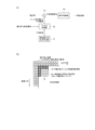
- (A) is a block diagram of the periphery of a filter processing unit related to a predicted image in the image coding apparatus according to the first embodiment of the present invention
- (b) is an explanatory diagram illustrating an example of filter processing of the predicted image.
- (A), (b), (c) is explanatory drawing which illustrates adjacent pixel non-reference prediction which concerns on this invention, respectively.
- It is a block diagram which shows one Example of the image coding apparatus of 1st Embodiment by this invention.
- (A) is a block diagram of the periphery of the filter processing unit related to a predicted image in the image coding apparatus according to the fourth embodiment of the present invention, and (b) is an explanatory diagram showing an example of filter processing of the predicted image. .
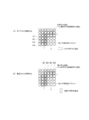
- (A), (b), (c) is explanatory drawing which illustrates the orthogonal transformation application block after the block division regarding the estimated image which concerns on this invention, respectively. It is a block diagram which shows one Example of the image coding apparatus of 4th Embodiment by this invention. It is a flowchart regarding the filter process of the estimated image in the image coding apparatus of 4th Embodiment by this invention.
- FIG. 1A is a block diagram of the periphery of the filter processing unit 12 related to a predicted image in the image coding apparatus 1 according to the first embodiment of the present invention, and FIG. It is explanatory drawing which shows the example of a filter process of an image.
- an adjacent pixel non-reference prediction unit 11 As shown in FIG. 1A, in the image coding device 1 according to the first embodiment of the present invention, an adjacent pixel non-reference prediction unit 11, a filter processing unit 12, a prediction residual signal generation unit 13, and an orthogonal transformation unit. 14 is provided.
- the adjacent pixel non-reference prediction unit 11 is a functional unit that performs signal prediction processing for generating a predicted image without using an adjacent decoded signal (decoded adjacent signal) for an encoding target region of the original image.
- signal prediction is referred to as “neighboring pixel non-reference prediction”.
- inter-prediction for performing motion compensation prediction between frames, different decoding of the same frame is performed.
- Prediction using intra block copy (Intra Block Copy) prediction which generates a predicted image by copying a partial image, and correlation between component signals of luminance signal and color difference signal at the corresponding block position of a certain frame
- Cross-component signal prediction for generating an image
- a frame F1 is an I frame (intra frame) in a plurality of frames F1 to F6 having a certain GOP structure
- a P frame predicted interframe
- a predicted image is generated with reference to past I frames or P frames, or a predicted image is generated with reference to a plurality of frames such as past and future frames such as a B frame (bi-predicted interframe).
- a decoded image Bkp is generated by referring to a different decoded partial image Bkr of the same frame F.
- a local decoded image of a luminance signal for example, Y signal
- a prediction image of the color difference signal for example, U / V signal
- synthesis processing by weighted addition to generate a corrected predicted image Bkp of the color difference signal (for example, U / V signal).
- the filter processing unit 12 is adjacent to each of the left side and the upper side of the prediction image among the pixel signals (prediction signals) in the block of the prediction image generated by the adjacent pixel non-reference prediction unit 11.
- a prediction image composed of a new prediction signal is generated by performing low-pass filter processing on the prediction signal using the decoded signal (decoded adjacent signal) to be transmitted to the prediction residual signal generation unit 13 It is a functional part that outputs.
- the filter processing unit 12 refers to the block Bkp of the predicted image made up of the 4 ⁇ 4 pixel signal p corresponding to the block Bko of the encoding target area of the original image, without referring to adjacent pixels.
- the prediction image is generated by the prediction unit 11, using the decoded adjacent signal So in the vicinity of the block boundary of the block Bkp of the prediction image adjacent on the left side and the upper side with respect to the prediction image.
- the pixel signal (prediction signal) is used as the signal Sf of the filter target region, and a low-pass filter process such as a smoothing filter in the horizontal direction and the vertical direction, for example, is performed to generate a prediction image composed of a new prediction signal. .
- the prediction residual signal generation unit 13 outputs each pixel of the block Bkp of the predicted image obtained from the filter processing unit 12 to each pixel signal (original signal) of the block (coding target block) Bko of the encoding target region of the original image.
- An error of the signal (prediction signal) is calculated and output to the orthogonal transformation unit 14 as a prediction residual signal.
- the orthogonal transform unit 14 performs a predetermined orthogonal transform process on the prediction residual signal input from the prediction residual signal generation unit 13 and generates a signal of the transform coefficient.
- a predetermined orthogonal transform process an orthogonal transform process used in an encoding method such as DCT or DST, or an integer orthogonal transform process defined by H.264 or H.265 that approximates an integer is used. It is possible to use any encoding scheme that can be used and conforms to the encoding method to be used.
- the image encoding device 1 performs quantization processing and entropy encoding processing on the signal of the transform coefficient and outputs the signal to the outside.
- video can be transmitted after being converted into a code by arithmetic encoding represented by CABAC together with various encoding parameters.
- the encoding parameters are transmitted including parameters that can be selected and set such as inter prediction parameters, intra prediction parameters, block size parameters related to block division (block division parameters), and quantization parameters related to quantization processing. be able to.
- an inter prediction unit 11a based on inter prediction will be described as a typical example of the adjacent pixel non-reference prediction unit 11, and an image code that performs filtering processing on the prediction signal of the block of the predicted image by the filter processing unit 12
- the configuration of the converter 1 and an example of its operation will be described with reference to FIGS.
- FIG. 3 is a block diagram showing an example of the image encoding device 1 according to the first embodiment of the present invention.
- the image encoding device 1 shown in FIG. 3 includes a preprocessing unit 10, an inter prediction unit 11a, a filter processing unit 12, a prediction residual signal generation unit 13, an orthogonal transformation unit 14, a quantization unit 15, Inverse quantization unit 16, inverse orthogonal transform unit 17, decoded image generation unit 18, in-loop filter unit 19, frame memory 20, intra prediction unit 21, motion vector calculation unit 22, and entropy encoding unit 23 and a predicted image selection unit 24.
- the preprocessing unit 10 divides the original image for each frame of the input moving image data into coding target blocks having a predetermined block size, and outputs them to the prediction residual signal generation unit 13 in a predetermined order.
- the prediction residual signal generation unit 13 calculates an error of each pixel signal of the block of the prediction image obtained from the filter processing unit 12 with respect to each pixel signal of the encoding target block, and performs orthogonal transform as a prediction residual signal in units of blocks. To the unit 14.
- the orthogonal transform unit 14 performs a predetermined orthogonal transform process on the prediction residual signal input from the prediction residual signal generation unit 13 and generates a signal of the transform coefficient.
- the quantization unit 15 performs a predetermined quantization process on the signal of the transform coefficient obtained from the orthogonal transform unit 14 and outputs the signal to the entropy coding unit 23 and the inverse quantization unit 16.
- the inverse quantization unit 16 performs inverse quantization processing on the quantized transform coefficient signal obtained from the quantization unit 15 and outputs the result to the inverse orthogonal transform unit 17.
- the inverse orthogonal transform unit 17 restores the prediction residual signal by performing an inverse orthogonal transform process on the signal of the transform coefficient after inverse quantization obtained from the inverse quantization unit 16, and outputs it to the decoded image generation unit 18. To do.
- the decoded image generation unit 18 adds the prediction residual signal restored by the inverse orthogonal transform unit 17 to the block of the prediction image predicted by the intra prediction unit 21 or the inter prediction unit 11a and obtained from the filter processing unit 12. Then, a block of the locally decoded image is generated and output to the in-loop filter unit 19.
- an adaptive loop filter ALF
- pixel adaptive offset SAO: Sample Adaptive Offset
- deblocking filter ALF
- In-loop filter processing such as the above is performed, and the result is output to the frame memory 20.
- the filter parameters relating to these filter processes are output to the entropy encoding unit 23 as one of the encoding parameters used as supplementary information for the encoding process.
- the frame memory 20 stores a block of a locally decoded image obtained through the in-loop filter unit 19 and holds it as a reference image that can be used by the intra prediction unit 21, the inter prediction unit 11a, and the motion vector calculation unit 22.
- the intra prediction unit 21 performs frame memory on the pixel signal (original signal) in the encoding target block of the original image when the prediction image selection unit 24 selects a signal that performs signal prediction using only the signal in the prediction target frame. 20 performs DC prediction, Planer prediction, or directionality prediction using the pixel signal of the encoded and decoded block adjacent to the left side or the upper side of the current encoding target block stored as a reference image, and predicts by extrapolation. A block of a predicted image made up of the pixel signals (predicted signals) thus generated is generated and output to the filter processing unit 12.
- an intra prediction parameter used to identify DC prediction, Planer prediction, or directionality prediction used in the intra prediction unit 21 is output to the entropy encoding unit 23 as one of encoding parameters that are supplementary information of the encoding process.
- the inter prediction unit 11a performs, with respect to the pixel signal (original signal) in the encoding target block of the original image, at the time of signal selection for performing motion compensation prediction between frames for the P / B frame by the predicted image selection unit 24.
- a block of a prediction image is generated by performing motion compensation on data stored as a reference image in the frame memory 20 with a motion vector provided from the motion vector calculation unit 22, and outputs the block to the filter processing unit 12.
- the motion vector calculation unit 22 searches the reference image data stored in the frame memory 20 for a position most similar to the encoding target block of the original image using a block matching technique or the like, and the space A value indicating an actual deviation is calculated as a motion vector and output to the inter prediction unit 11a.
- inter prediction parameter used for inter prediction including the motion vector calculated by the motion vector calculation unit 22 is output to the entropy encoding unit 23 as one of the encoding parameters used as supplementary information for the encoding process.
- the entropy encoding unit 23 performs entropy encoding processing on the output signal from the quantization unit 15 and various encoding parameters, and outputs a stream signal of encoded moving image data.
- step S1 when the filter processing unit 12 inputs a prediction image from the intra prediction unit 21 or the inter prediction unit 11a (step S1), whether or not the prediction image is adjacent pixel non-reference prediction, that is, In this example, whether or not the inter prediction is performed is identified based on the signal selection by the predicted image selection unit 24 (step S2).
- the adjacent pixel non-reference prediction is the intra block copy prediction or the cross component signal prediction described above.
- step S2 when the filter processing unit 12 determines that the predicted image is not adjacent pixel non-reference prediction, that is, intra prediction in this example (step S2: No), the filter processing unit 12 performs filter processing using a predetermined processing method. It is determined whether or not to execute (step S5). When the filter process is not performed on the prediction image of intra prediction (step S5: No), the filter processing unit 12 outputs the prediction signal to the prediction residual signal generation unit 13 without performing the filter process on the prediction signal. (Step S6). On the other hand, when performing a filter process with respect to the prediction image of intra prediction (step S5: Yes), the filter process part 12 transfers to step S3. It should be noted that the filtering process for the prediction image of the intra prediction may be performed in the same manner as the currently defined H.265, and is not directly related to the gist of the present invention. An example of executing filter processing on an image will be described.
- the filter processing unit 12 determines that the predicted image is adjacent pixel non-reference prediction, that is, inter prediction in this example (step S2: Yes)
- the pixel signal of the filter processing target area determined in advance from the predicted image. (Prediction signal) is selected (step S3). For example, as illustrated in FIG. 5, among the pixel signals (prediction signals) in the block of the 4 ⁇ 4 prediction image, the leftmost and uppermost pixel signals (prediction signals) of the prediction image are filtered. Determined as Sf.
- the filter processing unit 12 uses a decoded signal (decoded adjacent signal) adjacent to the left and upper sides with respect to the predicted image, and selects a pixel signal (predicted signal) in the selected filter processing target region. Then, a low-pass filter process is performed to generate a prediction image composed of a new prediction signal, and the prediction image is output to the prediction residual signal generation unit 13 (step S4).
- the filter processing unit 12 includes a horizontal filter region, a vertical filter region, and a vertical filter region in the filter processing target region Sf among the pixel signals (predicted signals) in the block Bkp of the 4 ⁇ 4 predicted image. Then, smoothing filter processing of a predetermined weight coefficient is performed on each of the angular filter regions and output to the prediction residual signal generation unit 13.
- the filter processing by the filter processing unit 12 may be low-pass filter processing, filter processing other than the smoothing filter can be applied, and the region and weighting factor of the decoded adjacent signal used for the filter processing can also be applied. It is not necessary to limit to the example shown in FIG. For example, in the case of a large-size encoded block, filter processing may be applied to a plurality of rows or columns. Further, the filter type, the filter processing target area, and the weighting coefficient related to the filter processing by the filter processing unit 12 can be configured to be transmitted as incidental information of the encoding process, but between transmission and reception (between encoding and decoding) ), It is not necessary to transmit.
- the filter processing unit 12 by performing the filtering process on the predicted image by the filter processing unit 12, the leftmost and uppermost pixel signals (predicted signal) in the predicted image regardless of the type of the orthogonal transform process of the orthogonal transform unit 14. And a decoded signal adjacent to this can be reduced, and the video encoding efficiency can be improved.
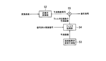
- FIG. 6 is a block diagram around the filter processing unit 54 related to a predicted image in the image decoding device 5 according to the first embodiment of the present invention.
- the image decoding device 5 according to the first embodiment of the present invention includes an inverse orthogonal transform unit 52, an adjacent pixel non-reference prediction unit 53, a filter processing unit 54, and a decoded image generation unit 55. Composed.
- the inverse orthogonal transform unit 52 is obtained by receiving the stream signal transmitted from the image encoding device 1 side and performing an inverse orthogonal transform process on the transform coefficient restored through the entropy decoding process and the inverse quantization process.
- the prediction residual signal is output to the decoded image generation unit 55.
- the adjacent pixel non-reference predicting unit 53 is a functional unit corresponding to the adjacent pixel non-reference predicting unit 11 on the image encoding device 1 side, and performs the prediction image without using the adjacent decoded signal (decoded adjacent signal).
- a signal prediction process to be generated is performed.
- the adjacent pixel non-reference prediction includes, for example, inter prediction that performs motion compensation prediction between frames, intra block copy (Intra Block Copy) prediction that generates a prediction image by copying different decoded partial images of the same frame, and Cross component signal prediction for generating a predicted image using the correlation between the component signals of the luminance signal and the color difference signal at the corresponding block position of a certain frame is included.
- the filter processing unit 54 is a functional unit corresponding to the filter processing unit 12 on the image encoding device 1 side, and the pixel signal (in the block of the predicted image generated by the adjacent pixel non-reference prediction unit 53) ( Prediction signal) using a decoded signal (decoded adjacent signal) adjacent to the left and upper sides of the predicted image, and applying a low-pass filter process to the predicted signal.
- a predicted image composed of a predicted signal is generated and output to the decoded image generation unit 55.
- the decoded image generation unit 55 adds the prediction residual signal restored by the inverse orthogonal transform unit 52 to the block of the prediction image obtained from the filter processing unit 54 described later, and generates a block of the decoded image made up of the decoded signal. It is a functional part.
- the filter processing unit 54 as in the case of the filter processing unit 12, the filter process may be a low-pass filter process, and a filter other than a smoothing filter can be applied. The region and weighting factor of the decoded adjacent signal to be used may be appropriately determined. Then, the filter type, the filter processing target area, and the weighting coefficient related to the filter processing by the filter processing unit 12 from the image encoding device 1 side are determined in advance between transmission and reception (between encoding and decoding) or encoded. When the information is transmitted as supplementary information of the process, the filter processing unit 54 of the image decoding device 5 performs the filtering process in the same manner, thereby improving the accuracy of the decoded signal.
- an inter prediction unit 53a based on inter prediction will be described as a typical example of the adjacent pixel non-reference prediction unit 53, and an image decoding device 5 that performs filter processing on the prediction signal based on the inter prediction by the filter processing unit 54.
- the configuration and the operation example will be described with reference to FIG.
- FIG. 7 is a block diagram showing an example of the image decoding device 5 according to the first embodiment of the present invention.
- the image decoding device 5 illustrated in FIG. 7 includes an entropy decoding unit 50, an inverse quantization unit 51, an inverse orthogonal transform unit 52, an inter prediction unit 53a, a filter processing unit 54, a decoded image generation unit 55, and a loop.
- An inner filter unit 56, a frame memory 57, an intra prediction unit 58, and a predicted image selection unit 59 are provided.
- the entropy decoding unit 50 receives the stream signal transmitted from the image encoding device 1 side and sets various encoding parameters obtained by performing entropy decoding processing corresponding to the entropy encoding processing of the image encoding device 1. In addition to outputting to the functional block, the quantized transform coefficient is output to the inverse quantization unit 51. As various encoding parameters, for example, a filter parameter, an intra prediction parameter, and an inter prediction parameter are output to the in-loop filter unit 56, the intra prediction unit 58, and the inter prediction unit 53a, respectively.
- the inverse quantization unit 51 performs an inverse quantization process corresponding to the quantization process of the image encoding device 1 on the quantized transform coefficient obtained from the entropy decoding unit 50, and converts the transform coefficient to an inverse orthogonal transform unit. To 52.
- the inverse orthogonal transform unit 52 restores the prediction residual signal by performing an inverse orthogonal transform process corresponding to the orthogonal transform process of the image encoding device 1 on the transform coefficient obtained from the inverse quantization unit 51, thereby decoding the decoded image
- the data is output to the generation unit 55.
- the decoded image generation unit 55 is restored by the inverse orthogonal transform unit 52 to a block of a prediction image that is predicted by the intra prediction unit 58 or the inter prediction unit 53a and is generated by applying the low-pass filter by the filter processing unit 54.
- the predicted residual signals are added to generate a decoded image block, which is output to the in-loop filter unit 56.
- the in-loop filter unit 56 performs a filter process corresponding to the in-loop filter process on the image encoding device 1 side, and outputs it to the frame memory 57.
- the frame memory 57 stores a block of a decoded image obtained through the in-loop filter unit 56 and holds it as a reference image that can be used by the intra prediction unit 58 and the inter prediction unit 53a.
- the intra prediction unit 58 selects the intra prediction parameters and the decoding target block stored as a reference image in the frame memory 57 when the prediction image selection unit 59 performs signal prediction using only signals in the prediction target frame.
- a prediction image block is generated by performing prediction processing corresponding to the intra prediction unit 21 on the image coding apparatus 1 side using pixel signals of decoded blocks adjacent to the left side or the upper side, and the filter processing unit 54 Output.
- the inter prediction unit 53a uses the motion vector included in the inter prediction parameter as a reference image in the frame memory 20 when selecting a signal for performing motion compensation prediction between frames for the P / B frame by the prediction image selection unit 59.
- a block of a predicted image is generated by motion compensation of the stored data, and is output to the filter processing unit 54.
- a frame can be constructed from the decoded data stored in the frame memory 57 and output as a decoded image.
- the filter processing unit 54 operates in the same manner as that illustrated and described with reference to FIGS. That is, the filtering process according to the present invention in the filter processing unit 54 is performed when the prediction image is adjacent pixel non-reference prediction, that is, in this example, when the prediction image is inter prediction.
- a pixel signal predicted signal
- a decoded signal decoded adjacent signal
- the filter processing unit 54 uses the decoded adjacent signal So in the vicinity of the block boundary of the block Bkp of the predicted image to use a pixel signal (predicted signal) in the block Bkp of the predicted image.
- a pixel signal predicted signal
- each of the horizontal filter region, the vertical filter region, and the angular filter region in the filter processing target region Sf is subjected to smoothing filter processing with a predetermined weight coefficient, and is output to the decoded image generation unit 55.
- the image encoding device 1 and the image decoding device 5 of the first embodiment configured as described above, a signal error generated between a prediction signal of a prediction image and an adjacent decoded block signal is reduced, and encoding is performed. Since the coding efficiency is improved, it is possible to realize an image coding apparatus and an image decoding apparatus of a video coding system with a high coding efficiency. That is, the residual component in the prediction residual signal can be further reduced, and the encoding efficiency can be improved by reducing the amount of information to be encoded and transmitted.
- the filter processing units 12 and 54 in the image encoding device 1 and the image decoding device 5 according to the second embodiment of the present invention will be described with reference to FIG.
- the filter processing units 12 and 54 of the first embodiment among the pixel signals (predicted signals) in the block of the predicted image generated by the adjacent pixel non-reference prediction, adjacent to the predicted image on the left side and the upper side, respectively.
- An example has been described in which a predicted image including a new predicted signal is generated by performing low-pass filter processing on the predicted signal using the decoded signal (decoded adjacent signal) to be performed.
- the filter processing units 12 and 54 of the present embodiment among the pixel signals (prediction signals) in the block of the prediction image generated by the adjacent pixel non-reference prediction, the decoded reference that is referred to in the low-pass filter processing Using the adjacent signal, a correlation determination is performed to determine whether or not to perform the low-pass filter processing on the prediction signal that is the target of the low-pass filter processing, and a low response is made according to the result of the correlation determination. It is configured to determine whether to apply pass-pass filtering. It should be noted that the same constituent elements will be described with the same reference numerals. Accordingly, the filter processing units 12 and 54 of the present embodiment can be applied to the image encoding device 1 and the image decoding device 5 illustrated in FIGS. 3 and 7, respectively. Only the processing contents related to the units 12 and 54 will be described, and further detailed description thereof will be omitted.
- FIG. 8 is a block diagram of the filter processing units 12 and 54 in the image encoding device 1 or the image decoding device 5 of the present embodiment.
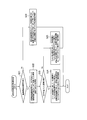
- FIG. 9 is a flowchart relating to prediction image filtering processes 12 and 54 in the image encoding device 1 or the image decoding device 5 of the present embodiment.
- the filter processing units 12 and 54 of the present embodiment include a horizontal direction correlation determination unit 101, a vertical direction correlation determination unit 102, a filter processing determination unit 103, and a filter processing execution unit 104.
- the operation of these functional blocks will be described with reference to the processing example shown in FIG.
- the filter processing units 12 and 54 of the present embodiment can be configured to perform processing regardless of whether adjacent pixel non-reference prediction is performed, for example, inter prediction or intra prediction.
- filter processing is performed on a prediction image of adjacent pixel non-reference prediction according to the present invention.
- the horizontal direction correlation determining unit 101 determines the correlation with the decoded adjacent signal adjacent to the left side of the predicted image (step S13), and when it is determined that the horizontal direction correlation is high (step S13: Yes). ), The execution of the horizontal filter processing is determined using the decoded adjacent signal (step S14), and when it is determined that the correlation in the horizontal direction is low (step S13: No), the horizontal filter processing is not executed.
- the data is output to the filter processing determination unit 103.
- the filter processing determination unit 103 determines whether or not it has been determined that both horizontal and vertical filter processing are to be executed (step S17), and receives that it has been determined that both horizontal and vertical filter processing are to be executed. If YES (step S17: Yes), it is determined that both horizontal and vertical filter processing and 3-tap angular filter processing are to be executed (step S18), and either or both of horizontal and vertical filter processing are executed. When it is received that it is not to be performed (step S17: No), it is determined that the filter process only in the horizontal direction is executed when the horizontal correlation is high, and the filter process only in the vertical direction is executed when the vertical correlation is high. In addition, when only one of horizontal and vertical filter processing is used, the angular filter also performs horizontal or vertical filter processing. It is determined as (Step S19).
- FIGS. 11 (b) and 11 (c) an example of a base waveform of orthogonal transform is shown in FIGS. 11 (b) and 11 (c).
- DCT realizes an orthogonal transform process in which the end points are open with a large value and the end portions of the transform base are open.
- the end point has a small value and is closed, and the orthogonal transform process in which the end of the transform base is closed is realized.
- the “orthogonal transformation process with the end of the transform base closed” refers to a block of the prediction residual signal whose one end close to the prediction reference block is closed.
- FIG. 7 the asymmetric DST type 7 may be a conversion basis with the other end open.
- the orthogonal transformation selection control unit 25 filters a non-executed prediction image for the filter processing.
- the block of the prediction residual signal obtained from the prediction residual signal generation unit 13 based on the block of the prediction image not executed for the low-pass filter processing from the processing unit 12 to the prediction residual signal generation unit 13
- the orthogonal transform unit 14 is instructed to use an orthogonal transform process (for example, DCT) in which the end of the transform base is open (step S6).
- the filter process is executed.
- the prediction image after the output is output from the filter processing unit 12 to the prediction residual signal generation unit 13, and the prediction residual signal obtained from the prediction residual signal generation unit 13 based on the block of the prediction image after the low-pass filter processing
- the orthogonal transform unit 14 is instructed to use an orthogonal transform process (for example, DST) in which the end of the transform base is closed (step S15).
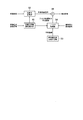
- FIG. 16 is a block diagram of the periphery of the filter processing unit 54 and the inverse orthogonal transform selection control unit 60 related to a predicted image in the image decoding device 5 of the present embodiment.
- the inverse orthogonal transform unit 52, the adjacent pixel non-reference prediction unit 53, the filter processing unit 54, the decoded image generation unit 55, and the inverse orthogonal transform selection control unit 60 is comprised so that it may comprise.
- the filter processing unit 54 operates under the control of the inverse orthogonal transform selection control unit 60 in the same manner as illustrated and described with reference to FIG.
- the filter processing according to the present embodiment in the filter processing unit 54 is performed when the prediction image is adjacent pixel non-reference prediction, that is, in this example, when the prediction image is inter prediction, a filter processing target area determined in advance from the prediction image.
- the pixel signal (predicted signal) of the selected filter processing target region is selected using the decoded signal (decoded adjacent signal) adjacent to the left or upper side of the predicted image. ) Is subjected to low-pass filter processing to generate a predicted image composed of a new predicted signal and output the decoded image to the decoded image generation unit 55. For example, as illustrated in FIG.
- a predetermined block size for example, the standard
- the block division is performed up to the block size that allows the above DST application
- the image encoding device 1 includes an adjacent pixel non-reference prediction unit 11, a filter processing unit 12, a prediction residual signal generation unit 13, and an orthogonal transformation unit 14. Configured.
- the orthogonal transformation unit 14 includes a block division unit 141 and an orthogonal transformation selection application unit 142.
- the filter processing unit 12 in the present embodiment is adjacent to each of the left side and the upper side of the prediction image among the pixel signals (prediction signals) in the block of the prediction image generated by the adjacent pixel non-reference prediction unit 11.
- a low-pass filter process is performed on the prediction signal to generate a prediction image including a new prediction signal, and the prediction image is output to the prediction residual signal generation unit 13 It is a functional part to do.
- a decoded adjacent signal (a pixel signal of the locally decoded image) located at the same coordinate in the horizontal direction.
- the smoothing filter processing is performed using the decoded adjacent signal (pixel signal of the locally decoded image) located at the same coordinate in the vertical direction.
- smoothing filter processing is performed using the pixels of the locally decoded video on the upper side and the left side.
- a 3-tap smoothing filter process using two reference pixels is applied.
- a low-pass filter process such as 1/4 [1 2 1] is applied. Note that the number of taps and reference pixels in the low-pass filter processing are not limited to this example.
- the block division unit 141 converts the block of the prediction residual signal with respect to the block Bkp of the prediction image including the 8 ⁇ 8 pixel signal p to 4 of the 4 ⁇ 4 prediction residual signal.
- the block is divided into two blocks (upper left, upper right, lower left and lower right) and output to the orthogonal transformation selection applying unit 142.
- the orthogonal transformation selection applying unit 142 applies the prediction residual signal divided blocks located at the upper end and the left end including the pixel position to which the smoothing filter process is applied among the divided blocks divided by the block dividing unit 141.
- a plurality of types of orthogonal transform processing (vertical / horizontal direction DST) corresponding to the position to which the smoothing filter processing is applied so that a transform coefficient using a high degree of correlation with a block of a decoded adjacent signal can be handled.
- a combination of vertical / horizontal DCT), and vertical / horizontal DCT orthogonal transform processing is applied to the other divided blocks.
- the vertical direction means the vertical direction
- the horizontal direction means the horizontal direction.
- the orthogonal transformation process consisting of the vertical direction DST and the horizontal direction DCT is the first orthogonal transformation process
- the orthogonal transformation process consisting of the horizontal direction DST and the vertical direction DCT is the second orthogonal transformation process
- the orthogonal transform process is referred to as a third orthogonal transform process
- the orthogonal transform process including the vertical and horizontal DCTs is referred to as a fourth orthogonal transform process.
- the subsequent orthogonal transformation selection applying unit 142 selects an orthogonal transformation suitable for the signal characteristic of the divided block of the prediction residual signal including the smoothing filter processing target pixel position. It becomes possible to apply.
- the orthogonal transform selection application unit 142 has a pixel to which the smoothing filter process is applied on the uppermost side among the divided blocks of the divided prediction residual signal (ie, smoothing). 20), the first orthogonal transform processing of the vertical direction DST and the horizontal direction DCT is applied to the divided block Bkt1 of the prediction residual signal located on the uppermost side (FIG. 20).
- a second orthogonal transform process in the horizontal direction DST and the vertical direction DCT is applied to Bkt2 (see FIG. 20C).
- the pixel to which the smoothing filter process is applied is on the uppermost side and on the leftmost side (that is, when the application direction of the smoothing filter process is the application direction of the angular filter process)
- the pixel is positioned in the corner region.
- the third orthogonal transform process in the vertical / horizontal direction DST is applied to the divided block Bkt3 to be performed.
- a plurality of types of orthogonal transform processing (a combination of vertical / horizontal direction DST and vertical / horizontal direction DCT) corresponding to the applied position is applied.
- These block division parameters related to the block division processing are output to the entropy encoding unit 23 (and the inverse orthogonal transform unit 17) as one of the encoding parameters used as supplementary information for the encoding processing.
- the inverse orthogonal transform unit 17 restores the prediction residual signal by performing an inverse orthogonal transform process on the signal of the transform coefficient after inverse quantization obtained from the inverse quantization unit 16, and outputs it to the decoded image generation unit 18. To do.
- the inverse orthogonal transform unit 17 determines the type of orthogonal transform processing for the transform coefficients that have been divided into blocks, performs the inverse orthogonal transform processing corresponding to each orthogonal transform processing, and performs parallel processing. Blocks corresponding to the block size of the predicted image are reconstructed by combining the divided blocks of the prediction residual signal that can be obtained, and output to the decoded image generation unit 18.
- step S1 when the filter processing unit 12 inputs a prediction image from the intra prediction unit 21 or the inter prediction unit 11a (step S1), whether or not the prediction image is adjacent pixel non-reference prediction, that is, In this example, whether or not the inter prediction is performed is identified based on the signal selection by the predicted image selection unit 24 (step S2).
- the adjacent pixel non-reference prediction is the intra block copy prediction or the cross component signal prediction described above.
- the orthogonal transform unit 14 divides the block of the prediction residual signal input from the prediction residual signal generation unit 13 into a block shape designated in advance by the block division unit 141 (Step S1). S11). At this time, the block division unit 141 predicts residuals located at the upper end and the left end of a predicted image block having a block size larger than 8 ⁇ 8 (for example, a predicted image having a block size of 32 ⁇ 32).
- the orthogonal transform unit 14 applies the pixel processing to which the filter processing by the filter processing unit 12 is applied. (That is, whether or not the prediction residual signal of the block including the pixel position on the uppermost side or the leftmost side of the predicted image) (step S12), and the pixel position to which the filter processing is applied is determined.
- step S12 the DCT fourth orthogonal transform process is applied to the divided block of the prediction residual signal in the vertical and horizontal directions (step S15).
- step S12 when it is determined that the block is a divided block including the pixel position to which the filter processing by the filter processing unit 12 is applied (step S12: Yes), whether only the vertical filter processing by the filter processing unit 12 is applied (ie, prediction) If it is a prediction residual signal of a block including only the uppermost pixel of the image) (step S13), if only the vertical filter processing is applied (step S13: Yes), the prediction residual signal The first orthogonal transform process in the vertical direction DST and the horizontal direction DCT is applied to the divided block of the difference signal (step S16).
- Step S14 When it is determined that the horizontal and vertical filter processing by the filter processing unit 12 is applied (that is, when the prediction residual signal of the block includes the pixel position on the uppermost side and the leftmost side of the predicted image) (Ste S14: No), the third orthogonal transformation process in the vertical and horizontal directions DST is applied to the divided block of the prediction residual signal (step S18).
- the block reconstructing unit 522 reconstructs a block corresponding to the block size of the predicted image by combining the divided blocks of the prediction residual signal obtained so that parallel processing is possible, and outputs the block to the decoded image generating unit 55.
- an inter prediction unit 53a based on inter prediction will be described as a typical example of the adjacent pixel non-reference prediction unit 53, and an image decoding device 5 that performs filter processing on the prediction signal based on the inter prediction by the filter processing unit 54.
- a configuration and an example of its operation will be described with reference to FIG.
- FIG. 25 is a block diagram showing an example of the image decoding device 5 of the present embodiment.
- the image decoding device 5 illustrated in FIG. 25 includes an entropy decoding unit 50, an inverse quantization unit 51, an inverse orthogonal transform unit 52, an inter prediction unit 53a, a filter processing unit 54, a decoded image generation unit 55, and a loop.
- An inner filter unit 56, a frame memory 57, an intra prediction unit 58, and a predicted image selection unit 59 are provided.
- the inverse orthogonal transform unit 52 restores the prediction residual signal by performing an inverse orthogonal transform process corresponding to the orthogonal transform process of the image encoding device 1 on the transform coefficient obtained from the inverse quantization unit 51, thereby decoding the decoded image
- the data is output to the generation unit 55.
- the inverse orthogonal transform unit 52 includes an inverse orthogonal transform selection application unit 521 and a block reconstruction unit 522, and the inverse orthogonal transform selection application unit 521 has transform coefficients that have been block-divided by the image encoding device 1 side. Are subjected to inverse orthogonal transform processing, and the divided blocks of the prediction residual signal are output to the block reconstructing unit 522.
- the block reconstruction unit 522 combines the divided blocks of the prediction residual signal obtained so that parallel processing is possible, configures a block corresponding to the block size of the predicted image, and outputs the block to the decoded image generation unit 55.
- the filter processing unit 54 uses the decoded adjacent signal So around the block boundary of the block Bkp of the predicted image, and outputs the pixel signal (in the block Bkp of the predicted image). Prediction signal) is subjected to smoothing filter processing with a predetermined weighting factor for each of the horizontal filter region, vertical filter region, and angular filter region in the filter processing target region Sf, and the result is output to the decoded image generation unit 55.
- a local decoded image for each divided block based on the block division processing of the block dividing unit 141 is acquired, and every time this local decoded image is acquired, adjacent pixel non-reference prediction is performed.
- the pixel signal (prediction signal) in the block of the generated prediction image is replaced, and the pixel signal (prediction signal) in the block of the prediction image is replaced in the block size unit of the divided block of the prediction residual signal.
- the low-pass filter process corresponding to each block size is performed on the predicted image Composed.
- the filter processing units 12 and 54 obtain a local decoded image for each divided block based on the block division processing of the block dividing unit 141, and the local decoded image is obtained. Every time it is acquired, the prediction image is updated by replacing the pixel signal (prediction signal) in the block of the prediction image generated by the adjacent pixel non-reference prediction, and the decoded image that is adjacent on the left side and the upper side with respect to the updated prediction image 19 (a) and FIG. 24, respectively, in that low-pass filter processing according to each block size is performed using the signal (decoded adjacent signal) and the local decoded image for each divided block.
- the configuration is different from that shown in FIG.
- FIG. 27 is a flowchart relating to prediction image filtering processes 12 and 54 in the image encoding device 1 or the image decoding device 5 of the present embodiment.
- FIG. 28 is an explanatory diagram relating to prediction image filtering processes 12 and 54 in the image encoding device 1 or the image decoding device 5 of the present embodiment.
- the filter processing units 12 and 54 obtain a local decoded image for each divided block based on the block division processing of the block dividing unit 141, and generate a predicted image that is replaced with the predicted image and updated. (Step S21). For example, as illustrated in FIG. 28, the block Bkp of the 8 ⁇ 8 predicted image is sequentially replaced with the block BkL of the locally decoded image having a block size divided into four in the order indicated by the white arrows, for example, and updated. However, the following processing shows the operation when the predicted image is updated with the local decoded image for each divided block (for example, “STEP 1” in the figure).
- the filter processing units 12 and 54 identify whether or not the predicted image is adjacent pixel non-reference prediction, for example, inter prediction (step S22). The same applies when the adjacent pixel non-reference prediction is the intra block copy prediction or the cross component signal prediction described above.
- the filter processing unit 12 or 54 determines that the predicted image is not adjacent pixel non-reference prediction, for example, intra prediction (step S22: No).
- the filter processing unit 12 or 54 performs filter processing using a predetermined processing method. It is determined whether or not to perform (step S25).
- the filter processing units 12 and 54 perform the prediction residual signal generation unit 13 or the like without performing the filter process on the predicted signal. It outputs to the decoded image generation part 55 (step S26).
- the filter process parts 12 and 54 transfer to step S23.
- the filtering process for the prediction image of the intra prediction may be performed in the same manner as H.265 currently specified, and is not directly related to the gist of the present invention. An example of executing filter processing on an image will be described.
- the filter processing unit 12 or 54 determines a filter processing target region that is determined in advance from the predicted image.
- a pixel signal (predicted signal) is selected (step S23).
- the leftmost and uppermost pixel signals (predicted signals) with respect to adjacent signals are defined as the filter processing target area Sf in units of 4 ⁇ 4 divided blocks.
- the filter processing units 12 and 54 perform the decoded signal (decoded adjacent signal) adjacent to the left side and / or the upper side for each divided block with respect to the prediction image replaced with the local decoded image of the divided block and the local unit.
- a prediction image including a new prediction signal is generated by performing low-pass filter processing on the pixel signal (prediction signal) of the selected filter processing target region, and the prediction residual signal generation unit 13 Or is output to the decoded image generation unit 55 (step S24).
- the low-pass filter processing is performed using the decoded signal (decoded adjacent signal) adjacent to the left side and / or the upper side of the predicted image and the local decoded image adjacent to the left side and / or the upper side for each divided block.
- the block Bkp of the 8 ⁇ 8 prediction image has not only the upper and left sides but also the pixel signal at the boundary position of the divided blocks that are crosses in this example. Is smoothed (for example, “STEP2” shown in the figure).
- the filter processing units 12 and 54 are configured as in the present embodiment, and are applied to the image encoding device 1 and the image decoding device 5, respectively, thereby improving the encoding efficiency and suppressing the deterioration of the image quality caused thereby. can do.
- a signal of a divided block other than the divided block located on the leftmost side or the uppermost side of the predicted image that can be a prediction residual signal having a large value (block located on the inner side of the predicted image when the block is divided) the divided block The value of the leftmost and topmost prediction residual signals for each can be reduced.
- the block shape at the time of block division is the same as that of the fourth embodiment, and the divided blocks positioned at the upper end and the left end of the corresponding prediction residual signal block are specified (this example In this case, it is preferable that the block size is 4 ⁇ 4), and that the other blocks are divided so as to have as large a block size as possible, and then re-divided according to the characteristics of the image to be encoded.
- the fourth embodiment has an advantage that parallel processing is possible because each divided block of the prediction residual signal can be processed independently.
- the embodiment since locally decoded images in units of divided blocks can be used sequentially, a greater improvement in coding efficiency can be expected.
- the block shape of block division can be variably set for each encoding target block, and the block division parameter can be transmitted as one of the encoding parameters. Therefore, the fourth embodiment is combined with the present embodiment. It can also be set as an embodiment.
- the present invention has been described by giving examples of specific embodiments. However, the present invention is not limited to the above-described examples, and various modifications can be made without departing from the technical idea thereof.
- the prediction image block size is smaller than the encoding target region.
- the present invention can also be applied to the case where the processing is performed with the block size to be subjected to orthogonal transformation processing smaller than the predicted image.
- the orthogonal transform process can be used as it is for the encoding process depending on the application, or may be different.
- the image decoding device 5 targets the transform coefficient related to the prediction residual signal encoded based on the prediction image subjected to the filter processing by the corresponding image encoding device 1.
- An example of decoding has been described, but if the use does not matter the restoration accuracy of the block edge with respect to the original image, the image decoding device 5 according to the present invention can perform the processing on the encoded signal without going through the filter process. Can also be decrypted by the same process.
- an image encoding device and an image decoding device of a video encoding method with high encoding efficiency can be realized, which is useful for applications where it is desired to improve the encoding efficiency of video transmission.
Landscapes
- Engineering & Computer Science (AREA)
- Multimedia (AREA)
- Signal Processing (AREA)
- Physics & Mathematics (AREA)
- Discrete Mathematics (AREA)
- General Physics & Mathematics (AREA)
- Compression Or Coding Systems Of Tv Signals (AREA)
Priority Applications (8)
| Application Number | Priority Date | Filing Date | Title |
|---|---|---|---|
| CN202110898950.0A CN113596443B (zh) | 2015-08-20 | 2016-08-19 | 图像编码装置 |
| EP22215855.2A EP4178204A1 (en) | 2015-08-20 | 2016-08-19 | Image decoding device, and image decoding method |
| EP16837188.8A EP3340621B1 (en) | 2015-08-20 | 2016-08-19 | Image decoding device, and programs therefor |
| CN201680053586.5A CN108028926B (zh) | 2015-08-20 | 2016-08-19 | 图像编码装置、图像解码装置 |
| JP2017535583A JP6464272B2 (ja) | 2015-08-20 | 2016-08-19 | 画像符号化装置、画像復号化装置、及びこれらのプログラム |
| US15/899,108 US11076149B2 (en) | 2015-08-20 | 2018-02-19 | Image encoding device, image decoding device, and program thereof |
| US17/354,881 US12149678B2 (en) | 2015-08-20 | 2021-06-22 | Image encoding device, image decoding device, and program thereof |
| US18/911,072 US20250039360A1 (en) | 2015-08-20 | 2024-10-09 | Image encoding device, image decoding device, and program thereof |
Applications Claiming Priority (6)
| Application Number | Priority Date | Filing Date | Title |
|---|---|---|---|
| JP2015-163260 | 2015-08-20 | ||
| JP2015163259 | 2015-08-20 | ||
| JP2015163260 | 2015-08-20 | ||
| JP2015-163259 | 2015-08-20 | ||
| JP2015-163257 | 2015-08-20 | ||
| JP2015163257 | 2015-08-20 |
Related Child Applications (1)
| Application Number | Title | Priority Date | Filing Date |
|---|---|---|---|
| US15/899,108 Continuation US11076149B2 (en) | 2015-08-20 | 2018-02-19 | Image encoding device, image decoding device, and program thereof |
Publications (1)
| Publication Number | Publication Date |
|---|---|
| WO2017030199A1 true WO2017030199A1 (ja) | 2017-02-23 |
Family
ID=58052066
Family Applications (3)
| Application Number | Title | Priority Date | Filing Date |
|---|---|---|---|
| PCT/JP2016/074291 Ceased WO2017030199A1 (ja) | 2015-08-20 | 2016-08-19 | 画像符号化装置、画像復号化装置、及びこれらのプログラム |
| PCT/JP2016/074290 Ceased WO2017030198A1 (ja) | 2015-08-20 | 2016-08-19 | 画像符号化装置、画像復号化装置、及びこれらのプログラム |
| PCT/JP2016/074293 Ceased WO2017030200A1 (ja) | 2015-08-20 | 2016-08-19 | 画像符号化装置、画像復号化装置、及びこれらのプログラム |
Family Applications After (2)
| Application Number | Title | Priority Date | Filing Date |
|---|---|---|---|
| PCT/JP2016/074290 Ceased WO2017030198A1 (ja) | 2015-08-20 | 2016-08-19 | 画像符号化装置、画像復号化装置、及びこれらのプログラム |
| PCT/JP2016/074293 Ceased WO2017030200A1 (ja) | 2015-08-20 | 2016-08-19 | 画像符号化装置、画像復号化装置、及びこれらのプログラム |
Country Status (5)
| Country | Link |
|---|---|
| US (7) | US11076149B2 (https=) |
| EP (3) | EP3340621B1 (https=) |
| JP (7) | JP6464272B2 (https=) |
| CN (4) | CN116760977A (https=) |
| WO (3) | WO2017030199A1 (https=) |
Families Citing this family (15)
| Publication number | Priority date | Publication date | Assignee | Title |
|---|---|---|---|---|
| JP6464272B2 (ja) * | 2015-08-20 | 2019-02-06 | 日本放送協会 | 画像符号化装置、画像復号化装置、及びこれらのプログラム |
| WO2018147329A1 (ja) * | 2017-02-10 | 2018-08-16 | パナソニック インテレクチュアル プロパティ コーポレーション オブ アメリカ | 自由視点映像生成方法及び自由視点映像生成システム |
| KR102822660B1 (ko) | 2018-04-04 | 2025-06-18 | 닛폰 호소 교카이 | 예측 화상 보정 장치, 화상 부호화 장치, 화상 복호 장치, 및 프로그램 |
| MX2021000173A (es) * | 2018-07-02 | 2021-05-27 | Huawei Tech Co Ltd | Aparato y metodo para filtrar en codificacion de video. |
| CN112585975B (zh) * | 2018-08-20 | 2024-08-09 | 日本放送协会 | 编码装置、解码装置以及程序 |
| US11758164B2 (en) * | 2018-10-23 | 2023-09-12 | Tencent America LLC | Method and apparatus for video coding |
| US11330283B2 (en) * | 2019-02-01 | 2022-05-10 | Tencent America LLC | Method and apparatus for video coding |
| JP7145793B2 (ja) * | 2019-03-11 | 2022-10-03 | Kddi株式会社 | 画像復号装置、画像復号方法及びプログラム |
| WO2020213946A1 (ko) | 2019-04-16 | 2020-10-22 | 엘지전자 주식회사 | 변환 인덱스를 이용하는 영상 코딩 |
| US12407873B2 (en) * | 2019-06-26 | 2025-09-02 | Ati Technologies Ulc | Metric driven adaptive processing for video encoders |
| WO2021040037A1 (ja) * | 2019-08-29 | 2021-03-04 | 日本放送協会 | 符号化装置、復号装置、及びプログラム |
| JP7483725B2 (ja) * | 2019-08-29 | 2024-05-15 | 日本放送協会 | 符号化装置、復号装置、及びプログラム |
| KR102932756B1 (ko) * | 2020-03-05 | 2026-03-05 | 삼성전자주식회사 | 이미징 장치 및 이를 포함하는 전자 기기 |
| CN111885378B (zh) * | 2020-07-27 | 2021-04-30 | 腾讯科技(深圳)有限公司 | 多媒体数据编码方法、装置、设备以及介质 |
| JP7742041B2 (ja) * | 2022-01-05 | 2025-09-19 | 株式会社アクセル | 符号化装置、復号装置、符号化方法、復号方法、符号化プログラム、及び復号プログラム |
Citations (2)
| Publication number | Priority date | Publication date | Assignee | Title |
|---|---|---|---|---|
| JP2011066569A (ja) * | 2009-09-16 | 2011-03-31 | Nippon Telegr & Teleph Corp <Ntt> | 予測信号生成方法,予測信号生成装置および予測信号生成プログラム |
| JP2013522957A (ja) * | 2010-03-10 | 2013-06-13 | トムソン ライセンシング | 変換選択を有するビデオ符号化および復号のための制約付きの変換を行う方法および装置 |
Family Cites Families (37)
| Publication number | Priority date | Publication date | Assignee | Title |
|---|---|---|---|---|
| JPH0319488A (ja) * | 1989-06-15 | 1991-01-28 | Matsushita Electric Ind Co Ltd | ブロック符号化装置と復号化装置 |
| JPH0813138B2 (ja) * | 1990-11-28 | 1996-02-07 | 松下電器産業株式会社 | 画像符号化装置 |
| CN1220391C (zh) * | 2001-06-29 | 2005-09-21 | 株式会社Ntt都科摩 | 图像编码装置、图像译码装置、图像编码方法和图像译码方法 |
| US7266150B2 (en) * | 2001-07-11 | 2007-09-04 | Dolby Laboratories, Inc. | Interpolation of video compression frames |
| US7376186B2 (en) * | 2002-07-15 | 2008-05-20 | Thomson Licensing | Motion estimation with weighting prediction |
| CN101951509B (zh) * | 2004-11-19 | 2012-05-23 | 松下电器产业株式会社 | 运动图像编码方法以及运动图像解码方法 |
| AU2006320064B2 (en) * | 2005-11-30 | 2010-09-09 | Kabushiki Kaisha Toshiba | Image encoding/image decoding method and image encoding/image decoding apparatus |
| KR100772873B1 (ko) * | 2006-01-12 | 2007-11-02 | 삼성전자주식회사 | 스무딩 예측을 이용한 다계층 기반의 비디오 인코딩 방법,디코딩 방법, 비디오 인코더 및 비디오 디코더 |
| JP4730552B2 (ja) * | 2006-07-14 | 2011-07-20 | 富士ゼロックス株式会社 | 復号化装置及びそのプログラム |
| KR100927733B1 (ko) * | 2006-09-20 | 2009-11-18 | 한국전자통신연구원 | 잔여계수의 상관성에 따라 변환기를 선택적으로 이용한부호화/복호화 장치 및 그 방법 |
| US9014280B2 (en) * | 2006-10-13 | 2015-04-21 | Qualcomm Incorporated | Video coding with adaptive filtering for motion compensated prediction |
| CN101711481B (zh) * | 2006-10-18 | 2013-01-09 | 汤姆森特许公司 | 使用预测数据精选进行视频编码的方法和装置 |
| JPWO2009133844A1 (ja) * | 2008-04-30 | 2011-09-01 | 株式会社東芝 | エッジを考慮したフィルタリング機能を備えた動画像符号化/復号化方法及び装置 |
| JP5137687B2 (ja) * | 2008-05-23 | 2013-02-06 | キヤノン株式会社 | 復号装置及び復号方法、プログラム |
| FR2948845A1 (fr) * | 2009-07-30 | 2011-02-04 | Thomson Licensing | Procede de decodage d'un flux representatif d'une sequence d'images et procede de codage d'une sequence d'images |
| WO2011083573A1 (ja) * | 2010-01-07 | 2011-07-14 | 株式会社 東芝 | 動画像符号化装置及び動画像復号化装置 |
| JP5302256B2 (ja) * | 2010-03-05 | 2013-10-02 | 日本放送協会 | 符号化装置、復号装置及びプログラム |
| CN102845062B (zh) * | 2010-04-12 | 2015-04-29 | 高通股份有限公司 | 用于几何运动分割的定点实施方案 |
| JP5875979B2 (ja) * | 2010-06-03 | 2016-03-02 | シャープ株式会社 | フィルタ装置、画像復号装置、画像符号化装置、および、フィルタパラメータのデータ構造 |
| WO2012029181A1 (ja) * | 2010-09-03 | 2012-03-08 | 株式会社 東芝 | 動画像符号化方法及び復号化方法、符号化装置及び復号化装置 |
| MX338462B (es) * | 2010-09-30 | 2016-04-15 | Mitsubishi Electric Corp | Dispositivo de codificacion de imagen en movimiento, dispositivo de decodificacion de imagen en movimiento, metodo de codificacion de imagen en movimiento y metodo de decodificacion de imagen en movimiento. |
| KR101772046B1 (ko) * | 2010-11-04 | 2017-08-29 | 에스케이텔레콤 주식회사 | 예측모드에 따라 필터링된 화소값으로 인트라예측을 수행하는 영상 부호화/복호화 방법 및 장치 |
| US9807424B2 (en) * | 2011-01-10 | 2017-10-31 | Qualcomm Incorporated | Adaptive selection of region size for identification of samples in a transition zone for overlapped block motion compensation |
| JP5298140B2 (ja) * | 2011-01-12 | 2013-09-25 | 株式会社エヌ・ティ・ティ・ドコモ | 画像予測符号化装置、画像予測符号化方法、画像予測符号化プログラム、画像予測復号装置、画像予測復号方法、及び画像予測復号プログラム |
| JP5291134B2 (ja) * | 2011-03-09 | 2013-09-18 | 日本電信電話株式会社 | 映像符号化/復号方法,映像符号化/復号装置およびそのプログラム |
| WO2012172667A1 (ja) * | 2011-06-15 | 2012-12-20 | 株式会社 東芝 | 動画像符号化方法、動画像復号化方法及び装置 |
| KR101362696B1 (ko) * | 2011-10-19 | 2014-02-17 | 전북대학교산학협력단 | 하이브리드 아키텍쳐가 적용된 신호 변환 장치, 신호 변환 방법 및 기록매체 |
| KR20130049523A (ko) * | 2011-11-04 | 2013-05-14 | 오수미 | 인트라 예측 블록 생성 장치 |
| KR20130050149A (ko) * | 2011-11-07 | 2013-05-15 | 오수미 | 인터 모드에서의 예측 블록 생성 방법 |
| JP2014036278A (ja) * | 2012-08-07 | 2014-02-24 | Nippon Hoso Kyokai <Nhk> | 画像符号化装置、画像復号装置及びプログラム |
| KR101650532B1 (ko) * | 2012-09-28 | 2016-08-23 | 니폰 덴신 덴와 가부시끼가이샤 | 인트라 예측 부호화 방법, 인트라 예측 복호 방법, 인트라 예측 부호화 장치, 인트라 예측 복호 장치, 이들의 프로그램 및 프로그램을 기록한 기록매체 |
| WO2015045736A1 (ja) * | 2013-09-30 | 2015-04-02 | 日本放送協会 | 画像符号化装置、画像復号装置及びそれらのプログラム |
| JP5802786B2 (ja) | 2014-03-25 | 2015-11-04 | 日本放送協会 | 符号化装置、復号装置及びプログラム |
| JP6464272B2 (ja) | 2015-08-20 | 2019-02-06 | 日本放送協会 | 画像符号化装置、画像復号化装置、及びこれらのプログラム |
| JPWO2017191749A1 (ja) * | 2016-05-02 | 2019-03-07 | ソニー株式会社 | 画像処理装置及び画像処理方法 |
| CN113557719B (zh) * | 2019-03-11 | 2023-09-12 | 日本放送协会 | 图像编码装置、图像解码装置和程序 |
| CN118018731A (zh) * | 2019-06-25 | 2024-05-10 | 日本放送协会 | 编码装置、解码装置和计算机可读存储介质 |
-
2016
- 2016-08-19 JP JP2017535583A patent/JP6464272B2/ja active Active
- 2016-08-19 WO PCT/JP2016/074291 patent/WO2017030199A1/ja not_active Ceased
- 2016-08-19 CN CN202310644968.7A patent/CN116760977A/zh active Pending
- 2016-08-19 EP EP16837188.8A patent/EP3340621B1/en active Active
- 2016-08-19 CN CN202110898950.0A patent/CN113596443B/zh active Active
- 2016-08-19 EP EP16837189.6A patent/EP3340622A4/en not_active Withdrawn
- 2016-08-19 JP JP2017535584A patent/JP6535744B2/ja not_active Expired - Fee Related
- 2016-08-19 EP EP22215855.2A patent/EP4178204A1/en active Pending
- 2016-08-19 CN CN201680053586.5A patent/CN108028926B/zh active Active
- 2016-08-19 WO PCT/JP2016/074290 patent/WO2017030198A1/ja not_active Ceased
- 2016-08-19 WO PCT/JP2016/074293 patent/WO2017030200A1/ja not_active Ceased
- 2016-08-19 CN CN201680053613.9A patent/CN108028927A/zh active Pending
-
2018
- 2018-02-19 US US15/899,108 patent/US11076149B2/en active Active
- 2018-02-19 US US15/899,130 patent/US10681346B2/en active Active
-
2019
- 2019-04-08 JP JP2019073846A patent/JP7186658B2/ja active Active
-
2020
- 2020-04-28 US US16/860,421 patent/US11843766B2/en active Active
-
2021
- 2021-06-22 US US17/354,881 patent/US12149678B2/en active Active
- 2021-07-06 JP JP2021112030A patent/JP7242768B2/ja active Active
-
2023
- 2023-03-08 JP JP2023035968A patent/JP7445799B2/ja active Active
- 2023-10-18 US US18/489,457 patent/US12192448B2/en active Active
-
2024
- 2024-02-26 JP JP2024026562A patent/JP7618864B2/ja active Active
- 2024-10-09 US US18/911,072 patent/US20250039360A1/en active Pending
- 2024-11-29 US US18/964,168 patent/US20250097406A1/en active Pending
-
2025
- 2025-01-08 JP JP2025002771A patent/JP7837442B2/ja active Active
Patent Citations (2)
| Publication number | Priority date | Publication date | Assignee | Title |
|---|---|---|---|---|
| JP2011066569A (ja) * | 2009-09-16 | 2011-03-31 | Nippon Telegr & Teleph Corp <Ntt> | 予測信号生成方法,予測信号生成装置および予測信号生成プログラム |
| JP2013522957A (ja) * | 2010-03-10 | 2013-06-13 | トムソン ライセンシング | 変換選択を有するビデオ符号化および復号のための制約付きの変換を行う方法および装置 |
Non-Patent Citations (2)
| Title |
|---|
| ATSURO ICHIGAYA ET AL.: "Inter coding with orthogonal transforms derived from DCT", THE INSTITUTE OF IMAGE INFORMATION AND TELEVISION ENGINEERS 2012 NEN NENJI TAIKAI KOEN YOKOSHU, THE INSTITUTE OF IMAGE INFORMATION AND TELEVISION ENGINEERS, 8 August 2012 (2012-08-08), pages 1 - 2, XP055515187 * |
| JICHENG AN ET AL.: "Non-CE7: Boundary-Dependent Transform for Inter-Predicted Residue", JOINT COLLABORATIVE TEAM ON VIDEO CODING (JCT-VC) OF ITU-T SG 16 WP3 AND ISO/IEC JTC1/SC29/WG11 JCTVC-G281, ITU-T, 30 November 2011 (2011-11-30), pages 1 - 11, XP030050406 * |
Also Published As
Similar Documents
| Publication | Publication Date | Title |
|---|---|---|
| JP7445799B2 (ja) | 画像復号装置及び画像復号方法 | |
| US12425609B2 (en) | Method and apparatus for encoding/decoding an image | |
| JP7848270B2 (ja) | ビデオ符号化における境界処理のための方法、装置及びプログラム |
Legal Events
| Date | Code | Title | Description |
|---|---|---|---|
| 121 | Ep: the epo has been informed by wipo that ep was designated in this application |
Ref document number: 16837188 Country of ref document: EP Kind code of ref document: A1 |
|
| ENP | Entry into the national phase |
Ref document number: 2017535583 Country of ref document: JP Kind code of ref document: A |
|
| NENP | Non-entry into the national phase |
Ref country code: DE |
|
| WWE | Wipo information: entry into national phase |
Ref document number: 2016837188 Country of ref document: EP |