WO2017030148A1 - Stainless steel foil - Google Patents
Stainless steel foil Download PDFInfo
- Publication number
- WO2017030148A1 WO2017030148A1 PCT/JP2016/074026 JP2016074026W WO2017030148A1 WO 2017030148 A1 WO2017030148 A1 WO 2017030148A1 JP 2016074026 W JP2016074026 W JP 2016074026W WO 2017030148 A1 WO2017030148 A1 WO 2017030148A1
- Authority
- WO
- WIPO (PCT)
- Prior art keywords
- stainless steel
- steel foil
- crystal grains
- plate thickness
- less
- Prior art date
Links
Classifications
-
- B—PERFORMING OPERATIONS; TRANSPORTING
- B32—LAYERED PRODUCTS
- B32B—LAYERED PRODUCTS, i.e. PRODUCTS BUILT-UP OF STRATA OF FLAT OR NON-FLAT, e.g. CELLULAR OR HONEYCOMB, FORM
- B32B15/00—Layered products comprising a layer of metal
- B32B15/04—Layered products comprising a layer of metal comprising metal as the main or only constituent of a layer, which is next to another layer of the same or of a different material
- B32B15/08—Layered products comprising a layer of metal comprising metal as the main or only constituent of a layer, which is next to another layer of the same or of a different material of synthetic resin
-
- C—CHEMISTRY; METALLURGY
- C21—METALLURGY OF IRON
- C21D—MODIFYING THE PHYSICAL STRUCTURE OF FERROUS METALS; GENERAL DEVICES FOR HEAT TREATMENT OF FERROUS OR NON-FERROUS METALS OR ALLOYS; MAKING METAL MALLEABLE, e.g. BY DECARBURISATION OR TEMPERING
- C21D1/00—General methods or devices for heat treatment, e.g. annealing, hardening, quenching or tempering
- C21D1/74—Methods of treatment in inert gas, controlled atmosphere, vacuum or pulverulent material
-
- C—CHEMISTRY; METALLURGY
- C21—METALLURGY OF IRON
- C21D—MODIFYING THE PHYSICAL STRUCTURE OF FERROUS METALS; GENERAL DEVICES FOR HEAT TREATMENT OF FERROUS OR NON-FERROUS METALS OR ALLOYS; MAKING METAL MALLEABLE, e.g. BY DECARBURISATION OR TEMPERING
- C21D8/00—Modifying the physical properties by deformation combined with, or followed by, heat treatment
- C21D8/02—Modifying the physical properties by deformation combined with, or followed by, heat treatment during manufacturing of plates or strips
- C21D8/0221—Modifying the physical properties by deformation combined with, or followed by, heat treatment during manufacturing of plates or strips characterised by the working steps
- C21D8/0236—Cold rolling
-
- C—CHEMISTRY; METALLURGY
- C21—METALLURGY OF IRON
- C21D—MODIFYING THE PHYSICAL STRUCTURE OF FERROUS METALS; GENERAL DEVICES FOR HEAT TREATMENT OF FERROUS OR NON-FERROUS METALS OR ALLOYS; MAKING METAL MALLEABLE, e.g. BY DECARBURISATION OR TEMPERING
- C21D8/00—Modifying the physical properties by deformation combined with, or followed by, heat treatment
- C21D8/02—Modifying the physical properties by deformation combined with, or followed by, heat treatment during manufacturing of plates or strips
- C21D8/0247—Modifying the physical properties by deformation combined with, or followed by, heat treatment during manufacturing of plates or strips characterised by the heat treatment
- C21D8/0257—Modifying the physical properties by deformation combined with, or followed by, heat treatment during manufacturing of plates or strips characterised by the heat treatment with diffusion of elements, e.g. decarburising, nitriding
-
- C—CHEMISTRY; METALLURGY
- C21—METALLURGY OF IRON
- C21D—MODIFYING THE PHYSICAL STRUCTURE OF FERROUS METALS; GENERAL DEVICES FOR HEAT TREATMENT OF FERROUS OR NON-FERROUS METALS OR ALLOYS; MAKING METAL MALLEABLE, e.g. BY DECARBURISATION OR TEMPERING
- C21D8/00—Modifying the physical properties by deformation combined with, or followed by, heat treatment
- C21D8/02—Modifying the physical properties by deformation combined with, or followed by, heat treatment during manufacturing of plates or strips
- C21D8/0247—Modifying the physical properties by deformation combined with, or followed by, heat treatment during manufacturing of plates or strips characterised by the heat treatment
- C21D8/0273—Final recrystallisation annealing
-
- C—CHEMISTRY; METALLURGY
- C21—METALLURGY OF IRON
- C21D—MODIFYING THE PHYSICAL STRUCTURE OF FERROUS METALS; GENERAL DEVICES FOR HEAT TREATMENT OF FERROUS OR NON-FERROUS METALS OR ALLOYS; MAKING METAL MALLEABLE, e.g. BY DECARBURISATION OR TEMPERING
- C21D9/00—Heat treatment, e.g. annealing, hardening, quenching or tempering, adapted for particular articles; Furnaces therefor
- C21D9/46—Heat treatment, e.g. annealing, hardening, quenching or tempering, adapted for particular articles; Furnaces therefor for sheet metals
- C21D9/48—Heat treatment, e.g. annealing, hardening, quenching or tempering, adapted for particular articles; Furnaces therefor for sheet metals deep-drawing sheets
-
- C—CHEMISTRY; METALLURGY
- C22—METALLURGY; FERROUS OR NON-FERROUS ALLOYS; TREATMENT OF ALLOYS OR NON-FERROUS METALS
- C22C—ALLOYS
- C22C38/00—Ferrous alloys, e.g. steel alloys
-
- C—CHEMISTRY; METALLURGY
- C25—ELECTROLYTIC OR ELECTROPHORETIC PROCESSES; APPARATUS THEREFOR
- C25D—PROCESSES FOR THE ELECTROLYTIC OR ELECTROPHORETIC PRODUCTION OF COATINGS; ELECTROFORMING; APPARATUS THEREFOR
- C25D11/00—Electrolytic coating by surface reaction, i.e. forming conversion layers
- C25D11/38—Chromatising
-
- B—PERFORMING OPERATIONS; TRANSPORTING
- B32—LAYERED PRODUCTS
- B32B—LAYERED PRODUCTS, i.e. PRODUCTS BUILT-UP OF STRATA OF FLAT OR NON-FLAT, e.g. CELLULAR OR HONEYCOMB, FORM
- B32B2457/00—Electrical equipment
- B32B2457/10—Batteries
-
- C—CHEMISTRY; METALLURGY
- C21—METALLURGY OF IRON
- C21D—MODIFYING THE PHYSICAL STRUCTURE OF FERROUS METALS; GENERAL DEVICES FOR HEAT TREATMENT OF FERROUS OR NON-FERROUS METALS OR ALLOYS; MAKING METAL MALLEABLE, e.g. BY DECARBURISATION OR TEMPERING
- C21D2211/00—Microstructure comprising significant phases
- C21D2211/001—Austenite
-
- C—CHEMISTRY; METALLURGY
- C21—METALLURGY OF IRON
- C21D—MODIFYING THE PHYSICAL STRUCTURE OF FERROUS METALS; GENERAL DEVICES FOR HEAT TREATMENT OF FERROUS OR NON-FERROUS METALS OR ALLOYS; MAKING METAL MALLEABLE, e.g. BY DECARBURISATION OR TEMPERING
- C21D2211/00—Microstructure comprising significant phases
- C21D2211/005—Ferrite
-
- H—ELECTRICITY
- H01—ELECTRIC ELEMENTS
- H01M—PROCESSES OR MEANS, e.g. BATTERIES, FOR THE DIRECT CONVERSION OF CHEMICAL ENERGY INTO ELECTRICAL ENERGY
- H01M50/00—Constructional details or processes of manufacture of the non-active parts of electrochemical cells other than fuel cells, e.g. hybrid cells
- H01M50/10—Primary casings, jackets or wrappings of a single cell or a single battery
-
- Y—GENERAL TAGGING OF NEW TECHNOLOGICAL DEVELOPMENTS; GENERAL TAGGING OF CROSS-SECTIONAL TECHNOLOGIES SPANNING OVER SEVERAL SECTIONS OF THE IPC; TECHNICAL SUBJECTS COVERED BY FORMER USPC CROSS-REFERENCE ART COLLECTIONS [XRACs] AND DIGESTS
- Y02—TECHNOLOGIES OR APPLICATIONS FOR MITIGATION OR ADAPTATION AGAINST CLIMATE CHANGE
- Y02E—REDUCTION OF GREENHOUSE GAS [GHG] EMISSIONS, RELATED TO ENERGY GENERATION, TRANSMISSION OR DISTRIBUTION
- Y02E60/00—Enabling technologies; Technologies with a potential or indirect contribution to GHG emissions mitigation
- Y02E60/10—Energy storage using batteries
Definitions
- the present invention relates to a stainless steel foil.
- the present invention relates to a stainless steel foil having good formability even though the plate thickness is extremely thin.
- a foil made of stainless steel (stainless steel foil) having higher strength and rigidity than aluminum has attracted attention.
- stainless steel has a higher specific gravity than aluminum, a stainless steel foil having an extremely thin plate thickness is required.
- it cannot be applied to a battery case required from current electronic equipment unless it is made an ultrathin stainless steel foil having a thickness of 60 ⁇ m or less.
- Patent Document 1 discloses a stainless steel foil having a thickness of 25 ⁇ m or less. When it becomes an ultra-thin stainless steel foil, a void accompanied by a crack occurs in the rolling direction from the etching end face. Patent Document 1 discloses an invention in which the number of inclusions of 5 ⁇ m or more is limited in order to solve this problem.
- Patent Documents 2 to 4 are examples in which stainless steel foil is applied to a battery case.
- Patent Document 2 presses a stainless steel foil having a thickness of 20 to 100 ⁇ m
- Patent Document 3 presses a stainless steel foil having a thickness of 100 ⁇ m
- Patent Document 4 presses a stainless steel foil having a thickness of 40 to 150 ⁇ m. Examples of battery exterior materials are disclosed.
- ultra-thin stainless steel foil is not annealed after rolling, as it is for springs used in HDD (Hard Disk Drive) head suspensions.
- punching or etching is performed after heat treatment for improving the proof stress.
- the technique of Patent Literature 1 solves the technical problem that occurs during such etching processing.
- the press formability is required to perform press working (deep drawing).
- a normal stainless steel foil having a thickness of 100 ⁇ m or more an annealing treatment of about 1000 ° C. is performed in the final process in order to improve workability, the internal dislocation density is lowered, and the elongation at break is ensured.
- the thickness of the stainless steel foil is 60 ⁇ m or less, the plastic deformability is significantly lowered, and the press formability (drawing workability) is deteriorated.
- the reason for this is that when the conventional annealing treatment is applied to a stainless steel foil having a thickness of 60 ⁇ m or less, the coarsening of the crystal grains in the stainless steel foil accelerates. It has been found that this is because the average crystal grain size is too large, especially because the number of crystal grains is about 1 to 2 in the plate thickness direction.
- the present inventors suppress the coarsening of the crystal grains, and even when the average crystal grain size of the crystal grains is reduced, It has been found that the crystal grains cannot be sufficiently deformed and breakage occurs.
- Patent Document 2 describes an example in which a stainless steel foil having a thickness of 20 to 100 ⁇ m is pressed and applied to a battery case.
- a stainless steel foil having a thickness of 20 to 100 ⁇ m is pressed and applied to a battery case.
- press workability plastic deformability
- the resin film peels off at the corner of the battery case. Even if the resin is peeled locally, if it is used as a battery case as it occurs, the resin will further peel from the site while in contact with the electrolyte for a long time. Impairs function.
- Patent Document 3 also describes an application example of a stainless steel foil having a thickness of 100 ⁇ m to a battery case.
- a stainless steel foil having a thickness of 100 ⁇ m the above-mentioned problems relating to press formability do not occur, and even if it occurs, the problem is not recognized in Patent Document 3, and therefore a solution is proposed. Absent.
- Patent Document 4 describes an example in which a stainless steel foil having a thickness of 40 to 150 ⁇ m is applied to a battery exterior material.
- the technique of Patent Document 4 suppresses generation of work-induced martensite during press working by nitriding the surface layer of a stainless steel foil.
- the press workability is improved because the surface unevenness formed by the processing-induced martensite transformation is suppressed and the surface smoothness is maintained.
- press formability can be improved by nitriding the surface layer while ensuring the above-mentioned number of crystal grains. This is because the thinner the plate thickness, the greater the influence of the hardening of the surface when nitriding, which induces cutting during press working.
- the present invention secures high plate thickness accuracy even with an ultrathin stainless steel foil having a thickness of 60 ⁇ m or less, and simultaneously ensures plastic deformability and elongation at break, that is, good press workability (deep drawing process). To secure the property).
- the surface roughness affects the plate thickness accuracy in the case of an ultrathin stainless steel foil, the surface roughness Rz should be suppressed to 1/10 of the plate thickness in order to ensure the plate thickness accuracy. Make it an issue.
- the elongation at break is to ensure 10% or more, which is the conventional stainless steel foil level. It is an object to secure the same level of plastic deformability as that of a conventional stainless steel foil.
- the lower limit of the plate thickness is not particularly limited, but the practical limit value of the thickness of the foil after rolling is about 5 ⁇ m, so the thickness of the stainless steel foil according to the present invention is 5-60 ⁇ m.
- the plastic deformability is ensured by securing three or more crystal grains in the thickness direction. Furthermore, in addition to making the crystal grains finer (decreasing the average crystal grain size), the crystal grain size distribution of the crystal grains should be narrowed according to the plate thickness.
- B In order to secure three or more crystal grains and narrow the crystal grain size distribution, it is only necessary to increase the dislocations that become nucleation sites by reducing the pressure during rolling, and then anneal. .
- Electrolytic solution resistance can be ensured by securing three or more crystal grains in the plate thickness direction and further by setting the nitrogen concentration of the surface layer to 1.0 mass% or less.
- it is important to suppress the rough surface of the stainless steel foil surface at the corner after press working and to maintain the adhesion with the resin film.
- the ultra-thin stainless steel foil with a thickness of 60 ⁇ m or less ensures high sheet thickness accuracy and simultaneously ensures plastic deformability and breaking elongation, that is, secures good press workability (deep drawing workability). can do. Furthermore, it is possible to ensure good electrolytic solution resistance when processed into a battery case. Accordingly, the present invention can be applied to a battery case such as a lithium ion battery that is aimed at reducing the size and weight.
- austenitic stainless steel will be described as an example.
- the stainless steel foil according to the present invention is not particularly limited as long as it is made of stainless steel.
- An austenite type such as SUS304 or a ferrite type such as SUS430 may be used.
- the suitable temperature for annealing is lower by about 100 ° C. than that of austenite. In view of this point, it was confirmed that according to the method for manufacturing a stainless steel foil described later, predetermined characteristics can be obtained regardless of whether it is austenite or ferrite.
- the stainless steel foil according to the present invention has a thickness of 5 to 60 ⁇ m. This is because, when the thickness is 60 ⁇ m or less, problems due to crystal grains become obvious as described above. Since these problems become more noticeable as the plate thickness becomes thinner, and further contributes to the reduction of the thickness of battery cases and the like, the upper limit of the target plate thickness may be limited in the direction of thinning. That is, it may be preferably limited to 50 ⁇ m or less, more preferably 40 ⁇ m or less, and even more preferably 25 ⁇ m or less. Further, the lower limit of the plate thickness is not particularly limited, but a plate thickness of 5 ⁇ m may be set as the lower limit in consideration of the limit of the manufacturing technique. Even if the plate thickness is 5 ⁇ m, the effect of the present invention can be enjoyed.
- the number of crystal grains in the plate thickness direction is calculated by measuring the crystal grain size in accordance with JIS G 0551 in any cross section in the plate thickness direction, calculating the average crystal grain size, and dividing the plate thickness by the average crystal grain size. The quotient can be used as the number of crystal grains in the plate thickness direction.
- a crystal grain is an equiaxed grain, it measures in the surface orthogonal to a plate
- crystal grains at the center in the width direction of stainless steel foil position of 1/2 width from one end
- the middle of both ends and the center two positions of 1/4 width and 3/4 width from one end
- the number of crystal grains in the plate thickness direction of the stainless steel foil can be evaluated by counting the number of these and arithmetically averaging them.
- the number of crystal grains obtained in this way should be three or more.
- Austenitic stainless steel has higher deformation resistance because it is easier to work harden than ferritic stainless steel. Further, the deformation resistance increases as the plate thickness increases. Therefore, from the viewpoint of ensuring plastic deformability, in the case of austenitic stainless steel, it is preferable to increase the number of crystal grains and increase the number of crystal grains as the plate thickness increases.
- the number of crystal grains in the plate thickness direction is preferably 5 or more when the plate thickness is 15 ⁇ m or more, and more preferably 10 or more when the plate thickness is 40 ⁇ m or more.
- the plate thickness is 15 ⁇ m or more
- 5 or more are more preferable when the thickness is 40 ⁇ m or more.
- the plastic deformability can be further improved.
- an ultrathin stainless steel foil having a plate thickness of 15 ⁇ m or less the influence of the steel type or plate thickness on the number of crystal grains in the plate thickness direction is negligible.
- the upper limit of the number of crystal grains is not particularly limited. This is because the number of crystal grains in the thickness direction changes depending on the thickness of the ultrathin stainless steel foil. This is because the multiple slip described above is determined not by the size of crystal grains but by the number of crystal grains in the thickness direction.
- the crystal grain size (crystal grain size in accordance with JIS G 0051 (hereinafter referred to as “average crystal grain size d” unless otherwise specified)) is 1 ⁇ m or more and 10 ⁇ m or less.
- the average crystal grain size d is preferably 2 ⁇ m or more and 6 ⁇ m or less.
- the area ratio occupied by crystal grains having a crystal grain size of t / 3 [ ⁇ m] or more is 20% or less
- the area ratio occupied by crystal grains having a crystal grain size of t / 3 [ ⁇ m] or more is 20%. It is as follows. As described above, when the plate thickness is 60 ⁇ m or less, the plastic deformability is lowered unless three or more crystal grains are secured in the plate thickness direction. At this time, even when the number of crystal grains in the plate thickness direction is 3 or more, crystal grains having a relatively large crystal grain size and crystal grains having a relatively small crystal grain size are arranged in the plate thickness direction.
- the crystal grain size distribution is preferably narrow.
- the ratio of crystal grains having a relatively large crystal grain size that is, crystal grains having a crystal grain size of t / 3 [ ⁇ m] or more is within the above range, whereby the stainless steel according to the present invention is obtained.
- the press formability of the steel foil can be further enhanced.
- the above area ratio may be calculated as follows. First, on the surface of the stainless steel foil, the average crystal grain size of crystal grains existing within a predetermined measurement field is measured according to JIS G 0551. Next, the measured crystal grain size is divided into a crystal grain having a measured crystal grain size of t / 3 [ ⁇ m] or more and a crystal grain having a measured crystal grain size of less than t / 3 [ ⁇ m]. The ratio of crystal grains having a diameter of t / 3 [ ⁇ m] or more to the area of the measurement visual field may be calculated and used as the area ratio. Or you may calculate using an electron beam backscattering diffraction (EBSD: Electron
- EBSD electron beam backscattering diffraction
- the crystal orientation at each measurement point is determined, and a boundary (excluding twins) having an inclination angle of 15 degrees or more is defined as a crystal grain boundary, and a region surrounded by the crystal grain boundary is defined as a crystal grain. Then, the crystal grain size and area of each crystal grain may be calculated to obtain the area ratio of crystal grains having a crystal grain size of t / 3 [ ⁇ m] or more.
- the area ratio is preferably 10% or less.
- the crystal grain size is calculated on the surface of the stainless steel foil, unlike the case of calculating the number of crystal grains in the plate thickness direction. This is because, when calculating the distribution of crystal grains having a predetermined crystal grain size, it is preferable that the number of crystal grains to be measured is larger, so a measurement field of view is ensured in an extremely thin foil cross section having a plate thickness of 60 ⁇ m or less. It is difficult to do.
- crystal grains may come into contact with the surface of the foil and may be interrupted in the middle.
- the crystal grain size in a discontinuous state is measured, the crystal grain size is calculated to be smaller than the actual crystal grain size, and the apparent crystal grain size becomes small.
- the crystal grain size is measured on the surface, since there is no crystal grain break in the middle, the advantage that a crystal grain size distribution reflecting the actual crystal grain size can be obtained. There is.
- the area ratio of crystal grains having a large crystal grain size is larger than the area ratio at the cross section in the plate thickness direction even with the same material. Therefore, if the area ratio on the surface is less than or equal to a predetermined value, it can be said that the area ratio in the plate thickness direction is surely smaller than that value. Therefore, in the present invention, the area ratio of crystal grains having a predetermined crystal grain size is When measuring, measure on the surface.
- the plastic deformability can be reduced by suppressing the coarsening of the recrystallized structure while reducing the dislocation density in the recrystallized grains. While ensuring, the elongation at break is also ensured.
- An example of a method for measuring the dislocation density is an etch pit method, but quantitative measurement is difficult because it is affected by measurement conditions.
- the dislocation density can be directly measured by microscopic observation, the variation is large due to the observation visual field. Therefore, the present inventors have found that it is possible to grasp whether proper heat treatment has been performed by measuring the recrystallization rate, which is a characteristic value reflecting the dislocation density.
- the recrystallization rate can be calculated by (area of recrystallized crystal) / (observation area).
- the “area of the recrystallized crystal” can be obtained by observing an arbitrary cross section of the ultrathin stainless steel foil under an optical microscope. Or you may calculate by calculating
- the stainless steel foil according to the present invention may have a recrystallization rate of 90% or more. If the recrystallization rate is 90% or more, the dislocation density is sufficiently low, and the number of crystal grains necessary in the plate thickness direction can be secured. Preferably, the recrystallization rate is 95% or more. This is because if the recrystallization rate is 95% or more, even if the plate thickness is thin, press workability (plastic deformability) is improved and surface roughness is also improved. If the number of crystal grains in the plate thickness direction satisfies the provisions of the present invention, the recrystallization rate may be 100%. That is, the entire stainless steel foil according to the present invention may be recrystallized.
- the surface layer of the stainless steel foil is not nitrided.
- the surface layer is not nitrided means that the nitrogen concentration of the surface layer is 1.0 mass% or less.
- the surface layer is a thickness at which the oxygen concentration is half the peak value in the measurement by Auger electron spectroscopy, and the nitrogen concentration is an average concentration in the surface layer.
- the surface layer of the stainless steel foil is nitrided, the surface layer is hardened by nitridation when it is pressed, so it becomes the starting point of cutting, so the press formability decreases. End up.
- the stainless steel foil according to the present invention having a thin plate thickness of 60 ⁇ m or less has a relatively large surface influence.
- the nitrogen concentration of the surface layer is preferably 1.0% by mass or less without concentrating nitrogen on the surface layer of the stainless steel foil.
- the lower limit is equivalent to the nitrogen content evaluated for the entire stainless steel foil. That is, in the case of steel types that do not contain nitrogen, such as general SUS304 and SUS430, the content level of nitrogen as an inevitable impurity is the lower limit.
- the nitrogen concentration in the surface layer of the stainless steel foil can be controlled to 1% by mass or less by setting the nitrogen concentration in the annealing atmosphere to 0.1% by volume or less.
- the stainless steel foil surface roughness Rz according to the present invention can be finished to 1/10 or less of the plate thickness. If the surface roughness Rz is 1/10 or less of the plate thickness, stable press workability (plastic deformability) can be ensured.
- the lower limit of the surface roughness Rz is not particularly limited. However, since it is not practical to set the surface roughness Rz to 0 nm, 100 nm, which is the minimum value that can be actually obtained, may be set as the lower limit.
- annealing at a relatively high temperature according to the dislocation density facilitates plastic deformation in the plate thickness direction due to the refinement of crystal grains, and avoids damage to the plate due to high elongation. As a result, it is estimated that high plate thickness accuracy can be secured.
- annealing occurs in a state where sufficient nucleation sites for recrystallization have not been obtained.
- the number will be about two. For this reason, plastic deformation is difficult to occur in the plate thickness direction, so that the roll pass plate causes the occurrence of warp or breakage during annealing.
- Elongation at break is 10% or more
- Elongation at break is a comprehensive index of workability and is related to plastic deformability and dislocation density. Since the dislocation density is closely related to the annealing temperature, if the final annealing temperature is 950 ° C. or higher, the elongation at break can be 10% or higher. Furthermore, since the stainless steel foil which concerns on this invention has also secured the plastic deformability, it was confirmed that fracture elongation is further favorable.
- the elongation at break of the stainless steel foil according to the present invention is 10% or more when the annealing temperature is 950 ° C., and 20% or more when the annealing temperature is 1050 ° C. It was confirmed that can be secured.
- the larger the elongation at break, the better, and the upper limit is not particularly limited. Since the practical maximum value of breaking elongation is about 50%, it may be the upper limit.
- the stainless steel foil according to the present invention may be made into a laminated stainless steel foil by laminating (laminating) a resin film on the surface thereof in the same manner as an ordinary laminated stainless steel foil.
- laminating the resin film By laminating the resin film, the corrosion resistance in the electrolytic solution can be improved, and the applicability to a battery case such as a lithium ion battery can be further enhanced.
- the lamination of the resin film may be performed on both surfaces of the stainless steel foil, or may be performed on either surface.
- Patent Document 5 discloses a technique in which a chromate treatment layer having a thickness of 2 to 200 nm is provided on at least one surface of a stainless steel foil, and a polyolefin-based resin containing a functional group having polarity is laminated on the surface. Yes.
- the resin after heat lamination may be made amorphous, and for this purpose, the cooling rate during heat lamination may be increased.
- the cooling rate in the range of 120 ° C. to 80 ° C. may be 20 ° C./s or more.
- the manufacturing process of the stainless steel foil according to the present invention is substantially the same as the manufacturing process of a normal stainless steel foil. That is, the stainless steel strip is foil-rolled, then the surface is cleaned, final annealing is performed, and temper rolling (tension leveler) is performed as necessary to produce a stainless steel foil. It should be noted that the foil rolling process may be divided into a plurality of times (multi-stage rolling) according to the thickness of the stainless steel strip used for foil rolling, and intermediate annealing may be performed between the foil rolling processes. However, in order to obtain the stainless steel foil according to the present invention, as described above, it is important to control the rolling reduction in final foil rolling and the temperature in final annealing.
- foil rolling In foil rolling, dislocations that serve as nucleation sites for recrystallization can be introduced into stainless steel by rolling under high pressure. The higher the rolling reduction, the more dislocations introduced. The dislocation density is controlled together by the rolling reduction and the annealing treatment performed after rolling. Therefore, when foil rolling is performed twice or more, the final foil rolling, that is, the foil rolling immediately before the final annealing may be performed under high pressure.
- ferritic stainless steel work hardening is difficult compared to austenitic stainless steel, that is, it is difficult to increase the dislocation density, so it is necessary to reduce the strength more and the reduction ratio should be 50% or more. If possible, it is preferably 60% or more, more preferably 70% or more.
- the degree of dislocation introduced by rolling varies depending on the steel type.
- the rolling reduction in foil rolling before final annealing is preferably 50% or more. From the viewpoint of securing the dislocation density, it is preferably 60% or more, and more preferably 70% or more.
- the rolling reduction in foil rolling before final annealing should be 30% or more.
- the rolling reduction in foil rolling before final annealing is preferably 40% or more, and more preferably 45% or more.
- Reduction ratio (sheet thickness before rolling ⁇ sheet thickness after rolling) / (sheet thickness before rolling)
- the upper limit of the rolling reduction is not particularly limited. However, theoretically, the rolling reduction rate cannot be 100%, so the practical upper limit of the rolling reduction rate is about 95%.
- the lower limit of the rolling reduction depends on the final thickness of the stainless steel foil, but is preferably 40% or more, more preferably 45% or more.
- the material structure When performing foil rolling in a plurality of times, it is preferable to control the material structure even in intermediate foil rolling and subsequent intermediate annealing. In this case as well, it may be the same as the final foil rolling. That is, the rolling reduction in each foil rolling is preferably 30% or more. However, since the foil rolling immediately before the final annealing is most effective as described above, the reduction rate of the final foil rolling may be set higher than the reduction rate of the other foil rolling.
- Annealing after foil rolling plays an important role in reducing dislocation density and promoting recrystallization.
- the object is to simultaneously suppress plastic growth and secure plastic deformability and elongation at break while reducing dislocation density and recrystallization. .
- the annealing temperature may be 950 ° C. or higher and 1050 ° C. or lower if it is an austenitic stainless steel. At 950 ° C. or lower, the dislocation density does not decrease, so that the elongation at break cannot be ensured. On the other hand, when the temperature exceeds 1050 ° C., the crystal becomes coarse, the number of crystal grains in the plate thickness direction is reduced, and the distribution of crystal grain size is widened, so that plastic deformability cannot be obtained.
- the lower limit of the annealing temperature is preferably slightly higher than 950 ° C., preferably 960 ° C., more preferably 970 ° C.
- the upper limit of the annealing temperature is preferably slightly lower than 1050 ° C. and preferably 1040 ° C., more preferably 1030 ° C., from the viewpoint of suppressing crystal coarsening.
- the annealing temperature may be 850 ° C. or higher and 950 ° C. or lower. At 850 ° C. or lower, the dislocation density does not decrease, so that the elongation at break cannot be ensured. On the other hand, if the temperature exceeds 950 ° C., the crystal becomes coarse, the number of crystal grains in the plate thickness direction is reduced, and the distribution of crystal grain size is widened, so that plastic deformability cannot be obtained.
- the lower limit of the annealing temperature is preferably slightly higher than 850 ° C., preferably 860 ° C., more preferably 870 ° C.
- the upper limit of the annealing temperature is preferably slightly lower than 950 ° C., preferably 940 ° C., more preferably 930 ° C., from the viewpoint of suppressing crystal coarsening.
- the time for holding the stainless steel foil at the above-described annealing temperature is preferably 3 seconds or more and 30 seconds or less. If it is less than 3 seconds, the heat treatment becomes insufficient and recrystallization does not proceed sufficiently, and the recrystallization rate specified in the present invention cannot be obtained. On the other hand, if it exceeds 30 seconds, the recrystallized grains become coarse, the number of crystal grains in the plate thickness direction is reduced, and the distribution of crystal grain sizes is widened, so that sufficient plastic deformability cannot be obtained.
- the annealing atmosphere is a rare gas atmosphere such as hydrogen or argon so that the surface of the stainless steel foil is not nitrided. Although it is desirable that the annealing atmosphere does not contain nitrogen at all, nitrogen mixed unavoidably from the atmosphere is acceptable to some extent. In order to set the nitrogen concentration of the surface layer to 1.0% by mass or less, the nitrogen concentration in the annealing atmosphere may be 0.1% by volume or less.
- intermediate annealing In the case of multiple foil rolling processes, the conditions for intermediate annealing are not particularly defined, but in the case of austenitic stainless steel, 950 ° C. or higher and 1050 ° C. or lower, and in the case of ferritic stainless steel, 850 ° C. or higher, as in the final annealing. 950 ° C. or lower is desirable. Since the crystal grain boundary is also a core of recrystallization and is preferably introduced before foil rolling, it is desirable to suppress the coarsening of the recrystallized grains by setting the temperature range as described above.
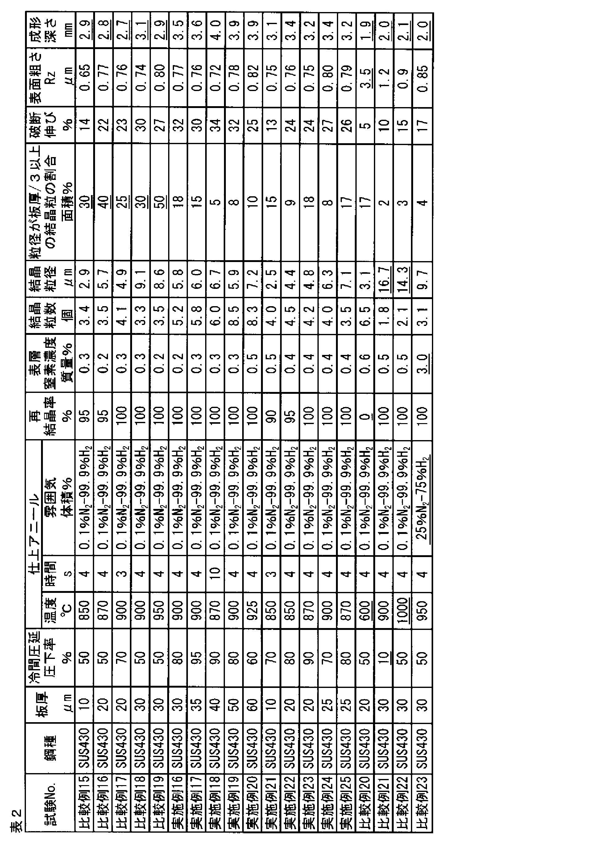
- stainless steel foil according to the present invention examples are shown in Tables 1 and 2 as stainless steel strips having a component of SUS304 (austenitic stainless steel) and stainless steel strips having a component of SUS430 (ferritic stainless steel).
- the ultrathin stainless steel foil which has the thickness of Table 1 and 2 was manufactured by rolling with a foil rolling machine on the rolling conditions of these.
- the cold rolling reduction ratio is the rolling reduction ratio in the foil rolling process immediately before the final annealing
- the finishing annealing temperature is the temperature in the final annealing process performed after the completion of the rolling process
- the holding time is to hold the stainless steel foil at the finishing annealing temperature. Each time is shown.
- the annealing atmosphere was 0.1 volume% -nitrogen 99.9 volume% hydrogen mixed gas or 25 volume% nitrogen-75 volume% hydrogen mixed gas.
- the recrystallization rate is determined by taking the cross section in the rolling direction as the observation surface, mirror polishing, etching and observing, obtaining the area of the recrystallized crystal grains in the range of the total plate thickness x 500 ⁇ m width, It was obtained by calculating (Area).
- the surface nitrogen concentration was measured by Auger electron spectroscopy (AES). Measurement was made from the stainless steel foil surface to a depth of 30 nm, and the average nitrogen concentration up to a depth at which the oxygen concentration was half the peak value was taken as the nitrogen concentration of the surface layer.
- AES Auger electron spectroscopy
- the number of crystal grains in the plate thickness direction is determined by measuring the crystal grain size in accordance with JIS G 0551 after cutting the test piece in the plate thickness direction, polishing the cross section, etching and then observing with a microscope. The diameter was calculated and taken as the quotient when the plate thickness was divided by the average crystal grain size.
- the average crystal grain size was calculated by measuring the crystal grain size according to JIS G 0551 after observing with a microscope after etching after polishing the surface of the test piece. Further, the area ratio occupied by crystal grains having a crystal grain size of t / 3 [ ⁇ m] or more is based on the calculated crystal grain size, and the crystal grains having a crystal grain size of t / 3 [ ⁇ m] or more; Distinguishing from crystal grains having a crystal grain size of less than 3 [ ⁇ m], the ratio of crystal grains having a crystal grain size of t / 3 [ ⁇ m] or more to the measurement field (100 ⁇ 100 ⁇ m) The area ratio was calculated.
- the elongation at break was evaluated by cutting out a JIS No. 13 B test piece from the manufactured stainless steel foil and performing a tensile test by a test method based on JIS Z 2241.
- the maximum height Rz was evaluated according to JIS B 0601 at a reference length of 0.25 mm using a commercially available stylus type surface roughness measuring instrument.
- the molding depth is preferably 3.0 mm or more, and when the plate thickness is 30 ⁇ m or more, the molding depth is preferably 3.5 mm or more. It was.
- the evaluation results are shown in Tables 1 and 2.
- the examples of the austenitic stainless steel foil according to the present invention satisfy all the rules regarding crystal grains.
- the molding depth when the plate thickness was less than 30 ⁇ m, the molding depth was 3.0 mm or more, and when the plate thickness was 30 ⁇ m or more, the molding depth was 3.5 mm or more.
- Comparative Examples 1 to 3 resulted in inferior molding depth because the area ratio occupied by crystal grains having a crystal grain size of t / 3 [ ⁇ m] or more exceeded 20%.
- Comparative Examples 4 to 7 did not satisfy all the regulations regarding crystal grains because the rolling reduction was low, the finish annealing temperature was high, or both. As a result, the molding depth was inferior.
- Comparative Examples 8 to 12 the recrystallization rate was low because the finish annealing temperature was low. As a result, the molding depth was inferior.
- Comparative Example 13 the nitrogen concentration in the surface layer was high because the nitrogen concentration contained in the atmosphere during the finish annealing was high. As a result, the molding depth was inferior.
- the reference example 14 relates to a conventional example having a large plate thickness.
- the examples of the ferritic stainless steel foil according to the present invention satisfy all the rules regarding crystal grains. As a result, when the plate thickness was less than 30 ⁇ m, the molding depth was 3.0 mm or more, and when the plate thickness was 30 ⁇ m or more, the molding depth was 3.5 mm or more.
- Comparative Examples 15 to 19 were inferior in molding depth because the area ratio occupied by crystal grains having a crystal grain size of t / 3 [ ⁇ m] or more exceeded 20%.
- Comparative Example 20 the recrystallization rate was low because the finish annealing temperature was low. As a result, the molding depth was inferior. Since Comparative Examples 21 and 22 had a low rolling reduction or a high finish annealing temperature, they did not satisfy the rules regarding the number of crystal grains in the plate thickness direction and the average crystal grain size. As a result, the molding depth was inferior. In Comparative Example 23, since the nitrogen concentration contained in the atmosphere during the finish annealing was high, the nitrogen concentration in the surface layer was high. As a result, the molding depth was inferior.
- the austenitic stainless steel foil had a difference of 0.5 mm or more with respect to the forming depth when the example and the comparative example were compared.
- the ferritic stainless steel foil it was confirmed that there was a difference of 0.4 mm or more with respect to the molding depth when the example and the comparative example were compared.
- This difference is very significant as shown below. That is, for example, when the stainless steel foil is applied to a battery case mounted on a small and light electronic device such as a smartphone, the thickness of the battery case is required to be about several mm. In such a situation, if the molding depth is increased by 0.4 mm or more, it corresponds to 10% or more of the thickness of the battery case, which greatly contributes to an increase in battery capacity. Therefore, the effect of the present invention is very large.
- the stainless steel foil according to the present invention can be applied to battery cases such as lithium ion batteries for small electronic devices.
Abstract
Description
(ア)板厚方向の結晶粒の数を3個以上確保することにより、塑性変形能が確保されること。さらに、結晶粒は微細化する(平均結晶粒径を小さくする)ことに加えて、板厚に応じて結晶粒の結晶粒径分布を狭くすること。
(イ)結晶粒の数を3個以上確保し、結晶粒の結晶粒径分布を狭くするためには、圧延時に強圧下して核生成サイトとなる転位を増やし、その後アニールを行えばよいこと。
(ウ)破断伸びを10%以上確保するためには、転位密度に応じた高温でアニールを行い、再結晶率を90%以上にすることにより達成することができること。さらに、表面硬化による切れ(割れ)を抑制するために、表層の窒化を極力抑制することが重要であること。
(エ)上記の塑性変形能と破断伸びを同時に確保すれば、表面粗さ(Rz(JIS B 0601:2001))は100nm~板厚の1/10以下という高い板厚精度も同時に確保できること。
(オ)板厚方向の結晶粒の数を3個以上確保し、さらに表層の窒素濃度を1.0質量%以下とすることにより、耐電解液性も確保できること。つまり、耐電解液性を向上するには、プレス加工後のコーナー部でのステンレス鋼箔表面の肌荒れを抑制し、樹脂皮膜との密着性を保つことが重要であること。 In order to solve the above problems, the present inventors have intensively studied and obtained the following knowledge.
(A) The plastic deformability is ensured by securing three or more crystal grains in the thickness direction. Furthermore, in addition to making the crystal grains finer (decreasing the average crystal grain size), the crystal grain size distribution of the crystal grains should be narrowed according to the plate thickness.
(B) In order to secure three or more crystal grains and narrow the crystal grain size distribution, it is only necessary to increase the dislocations that become nucleation sites by reducing the pressure during rolling, and then anneal. .
(C) In order to ensure the elongation at break of 10% or more, it can be achieved by annealing at a high temperature according to the dislocation density and setting the recrystallization rate to 90% or more. Furthermore, it is important to suppress nitridation of the surface layer as much as possible in order to suppress breakage (cracking) due to surface hardening.
(D) If the above-mentioned plastic deformability and elongation at break are ensured at the same time, the surface roughness (Rz (JIS B 0601: 2001)) can simultaneously ensure a high plate thickness accuracy of 100 nm to 1/10 of the plate thickness.
(E) Electrolytic solution resistance can be ensured by securing three or more crystal grains in the plate thickness direction and further by setting the nitrogen concentration of the surface layer to 1.0 mass% or less. In other words, in order to improve the resistance to electrolytic solution, it is important to suppress the rough surface of the stainless steel foil surface at the corner after press working and to maintain the adhesion with the resin film.
(1)板厚が5μm以上60μm以下であるステンレス鋼箔であって、
前記ステンレス鋼箔の再結晶率が90%以上100%以下であり、
前記ステンレス鋼箔の表層の窒素濃度が1.0質量%以下であり、
前記ステンレス鋼箔の板厚方向に結晶粒を3個以上有し、
前記結晶粒の平均結晶粒径dが1μm以上10μm以下であり、
前記板厚をt[μm]とした場合に、t/3[μm]以上の結晶粒径を有する結晶粒が占める面積率が20%以下であることを特徴とするステンレス鋼箔である。
(2)前記板厚が5μm以上25μm以下であることを特徴とする(1)に記載のステンレス鋼箔である。
(3)表面粗さRzが100nm以上、且つ板厚の1/10以下であることを特徴とする(1)または(2)に記載のステンレス鋼箔である。
(4)破断伸びが10%以上であることを特徴とする(1)から(3)のいずれかに記載のステンレス鋼箔である。
(5)前記ステンレス鋼箔がフェライト系ステンレス鋼箔であることを特徴とする(1)から(4)のいずれかに記載のステンレス鋼箔である。
(6)前記ステンレス鋼箔がオーステナイト系ステンレス鋼箔であることを特徴とする(1)から(4)のいずれかに記載のステンレス鋼箔である。
(7)前記ステンレス鋼箔の少なくとも一方の表面に樹脂フィルムが積層されていることを特徴とする(1)から(6)のいずれかに記載のステンレス鋼箔である。 This invention is made | formed based on these knowledge, The place made into the summary is as follows.
(1) A stainless steel foil having a plate thickness of 5 μm or more and 60 μm or less,
The recrystallization rate of the stainless steel foil is 90% or more and 100% or less,
The nitrogen concentration of the surface layer of the stainless steel foil is 1.0 mass% or less,
Having three or more crystal grains in the thickness direction of the stainless steel foil,
The average grain size d of the crystal grains is 1 μm or more and 10 μm or less,
When the plate thickness is t [μm], the area ratio occupied by crystal grains having a crystal grain size of t / 3 [μm] or more is 20% or less.
(2) The stainless steel foil according to (1), wherein the plate thickness is 5 μm or more and 25 μm or less.
(3) The stainless steel foil according to (1) or (2), wherein the surface roughness Rz is 100 nm or more and 1/10 or less of the plate thickness.
(4) The stainless steel foil according to any one of (1) to (3), wherein elongation at break is 10% or more.
(5) The stainless steel foil according to any one of (1) to (4), wherein the stainless steel foil is a ferritic stainless steel foil.
(6) The stainless steel foil according to any one of (1) to (4), wherein the stainless steel foil is an austenitic stainless steel foil.
(7) The stainless steel foil according to any one of (1) to (6), wherein a resin film is laminated on at least one surface of the stainless steel foil.
[ステンレス鋼の材質]
本発明に係るステンレス鋼箔は、ステンレス鋼から構成されていれば、特に制限されない。SUS304などのオースナイト系であってもよいし、SUS430などのフェライト系であってもよい。ただし、フェライト系ステンレス鋼の場合、オーステナイト系に比較してアニールの適性温度が約100℃低くなる。その点を考慮し、後述するステンレス鋼箔の製造方法によれば、オーステナイト系であってもフェライト系であっても所定の特性を得ることができることを確認した。 (1. Stainless steel foil)
[Material of stainless steel]
The stainless steel foil according to the present invention is not particularly limited as long as it is made of stainless steel. An austenite type such as SUS304 or a ferrite type such as SUS430 may be used. However, in the case of ferritic stainless steel, the suitable temperature for annealing is lower by about 100 ° C. than that of austenite. In view of this point, it was confirmed that according to the method for manufacturing a stainless steel foil described later, predetermined characteristics can be obtained regardless of whether it is austenite or ferrite.
本発明に係るステンレス鋼箔は、板厚が5~60μmのものを対象とする。60μm以下であると、前述したように結晶粒起因の問題点が顕在化するからである。これらの問題点は板厚が薄くなればなるほど顕著になること、さらには電池ケースなどの薄厚化に貢献できることから、対象板厚の上限を薄厚化の方向へ限定してもよい。すなわち、好ましくは50μm以下、さらに好ましくは40μm以下、より好ましくは25μm以下に限定してもよい。また、板厚の下限は特に限定しないが、製造技術の限界を考慮すると板厚5μmを下限としてもよい。板厚5μmであっても、本発明による効果は享受できる。 [Thickness is 5-60μm]
The stainless steel foil according to the present invention has a thickness of 5 to 60 μm. This is because, when the thickness is 60 μm or less, problems due to crystal grains become obvious as described above. Since these problems become more noticeable as the plate thickness becomes thinner, and further contributes to the reduction of the thickness of battery cases and the like, the upper limit of the target plate thickness may be limited in the direction of thinning. That is, it may be preferably limited to 50 μm or less, more preferably 40 μm or less, and even more preferably 25 μm or less. Further, the lower limit of the plate thickness is not particularly limited, but a plate thickness of 5 μm may be set as the lower limit in consideration of the limit of the manufacturing technique. Even if the plate thickness is 5 μm, the effect of the present invention can be enjoyed.
本発明に係るステンレス鋼箔において、板厚方向に結晶粒が3個以上存在する。板厚方向の結晶粒数は、板厚方向の任意の断面において、結晶粒径をJIS G 0551に準拠して測定して平均結晶粒径を算出し、板厚を平均結晶粒径で割り算し、その商をもって板厚方向の結晶粒数とすることができる。なお、結晶粒が等軸粒である場合は、板厚方向に直交する面において測定し、平均結晶粒径を算出してもよい。 [3 or more crystal grains in the plate thickness direction]
In the stainless steel foil according to the present invention, there are three or more crystal grains in the thickness direction. The number of crystal grains in the plate thickness direction is calculated by measuring the crystal grain size in accordance with JIS G 0551 in any cross section in the plate thickness direction, calculating the average crystal grain size, and dividing the plate thickness by the average crystal grain size. The quotient can be used as the number of crystal grains in the plate thickness direction. In addition, when a crystal grain is an equiaxed grain, it measures in the surface orthogonal to a plate | board thickness direction, and may calculate an average crystal grain diameter.
本発明では、結晶粒の大きさ(JIS G 0051に準拠する結晶粒径(以下、本明細書では特に断りのない限り「平均結晶粒径d」という。))を1μm以上10μm以下とする。平均結晶粒径dは2μm以上6μm以下であることが好ましい。 [Average crystal grain size is 1 μm or more and 10 μm or less]
In the present invention, the crystal grain size (crystal grain size in accordance with JIS G 0051 (hereinafter referred to as “average crystal grain size d” unless otherwise specified)) is 1 μm or more and 10 μm or less. The average crystal grain size d is preferably 2 μm or more and 6 μm or less.
本発明では、上記の平均結晶粒径に関する規定に加えて、板厚をt[μm]とした場合に、t/3[μm]以上の結晶粒径を有する結晶粒が占める面積率を20%以下としている。上述したように、板厚が60μm以下になると、板厚方向の結晶粒数を3個以上確保しなければ、塑性変形能が低下してしまう。このとき、板厚方向の結晶粒数を3個以上確保した場合であっても、結晶粒径が比較的大きな結晶粒と結晶粒径が比較的小さい結晶粒とが板厚方向に並んでいる場合と、結晶粒径が同程度の結晶粒が板厚方向に並んでいる場合と、では、塑性変形能に差が生じる。たとえば、結晶粒径が大きい結晶粒が、変形に不利な方位に存在していると、当該結晶粒が十分に変形できないので、当該結晶粒を起点として破断等が生じてしまう。 [The area ratio occupied by crystal grains having a crystal grain size of t / 3 [μm] or more is 20% or less]
In the present invention, in addition to the above-mentioned provision concerning the average crystal grain size, when the plate thickness is t [μm], the area ratio occupied by crystal grains having a crystal grain size of t / 3 [μm] or more is 20%. It is as follows. As described above, when the plate thickness is 60 μm or less, the plastic deformability is lowered unless three or more crystal grains are secured in the plate thickness direction. At this time, even when the number of crystal grains in the plate thickness direction is 3 or more, crystal grains having a relatively large crystal grain size and crystal grains having a relatively small crystal grain size are arranged in the plate thickness direction. There is a difference in plastic deformability between the case and the case where crystal grains having the same crystal grain size are arranged in the plate thickness direction. For example, if a crystal grain having a large crystal grain size is present in an orientation that is disadvantageous for deformation, the crystal grain cannot be sufficiently deformed, and breakage or the like occurs from the crystal grain as a starting point.
本発明に係るステンレス鋼箔は、塑性変形能を確保するため結晶粒を微細化する必要があるが、それだけでは前述の課題を解決できない。さらに破断伸び性を確保するために転位密度を適正なレベルに調整する必要がある。具体的には、圧延後の組織は加工を受けることにより、転位などの格子欠陥が蓄積しているため、結晶粒は微細であっても転位密度が高く、硬化している。そのため、熱処理条件を材料に応じて適正に制御して、組織を再結晶させ、低転位密度にする必要がある。すなわち、再結晶組織が転位密度を駆動力として形成されるために、再結晶粒内の転位密度を小さくすることを利用しつつ、再結晶組織の粗大化を抑制することで、塑性変形能を確保しつつ、破断伸び性も確保するものである。 [Recrystallization rate is 90% or more and 100% or less]
In the stainless steel foil according to the present invention, it is necessary to refine crystal grains in order to ensure plastic deformability, but that alone cannot solve the aforementioned problems. Furthermore, it is necessary to adjust the dislocation density to an appropriate level in order to ensure break elongation. Specifically, since the structure after rolling is processed, lattice defects such as dislocations are accumulated, so that even if the crystal grains are fine, the dislocation density is high and hardened. For this reason, it is necessary to appropriately control the heat treatment conditions according to the material to recrystallize the structure to obtain a low dislocation density. In other words, since the recrystallized structure is formed using the dislocation density as a driving force, the plastic deformability can be reduced by suppressing the coarsening of the recrystallized structure while reducing the dislocation density in the recrystallized grains. While ensuring, the elongation at break is also ensured.
上述したように、ステンレス鋼箔の表面を窒化した場合、特に板厚が薄くなると、窒化による表層の硬化に起因する種々の問題点が顕在化する。したがって、ステンレス鋼箔の表層は窒化していないことが望ましい。「表層が窒化していない」とは、表層の窒素濃度が1.0質量%以下であることを意味する。ここで、表層とはオージェ電子分光法による測定において、酸素濃度がピーク値の半分となる厚さのこととし、窒素濃度は、表層における平均の濃度とする。 [Nitrogen concentration in the surface layer]
As described above, when the surface of the stainless steel foil is nitrided, various problems due to the hardening of the surface layer due to nitridation become apparent especially when the plate thickness is reduced. Therefore, it is desirable that the surface layer of the stainless steel foil is not nitrided. “The surface layer is not nitrided” means that the nitrogen concentration of the surface layer is 1.0 mass% or less. Here, the surface layer is a thickness at which the oxygen concentration is half the peak value in the measurement by Auger electron spectroscopy, and the nitrogen concentration is an average concentration in the surface layer.
上記板厚方向の結晶粒数および再結晶率を確保するために、強圧下率で圧延し、比較的高温で最終アニールを施す。それらのプロセスを経ることにより、表面粗さRzは、光沢のある通常品でも1000nm以下に、表面に光沢のないダル仕上げ品であっても6000nm以下となることが確認できた。なお、Rzとは、JIS B 0601: 2001で規定されているように、基準長さにおいて、最も凹な部分と最も凸な部分との厚み方向の差で表現される。いうまでもなく、表面粗さの上限は低ければ低いほどよいが、実際のプロセス条件に依存する。本発明に係るステンレス鋼箔表面粗さRzは、板厚の1/10以下に仕上げることができる。表面粗さRzが板厚の1/10以下であれば、安定したプレス加工性(塑性変形能)が確保できる。 [Surface roughness Rz is 100 nm or more and 1/10 or less of the plate thickness]
In order to ensure the number of crystal grains and the recrystallization rate in the plate thickness direction, rolling is performed at a high reduction rate, and final annealing is performed at a relatively high temperature. Through these processes, it was confirmed that the surface roughness Rz was 1000 nm or less even for a glossy normal product, and 6000 nm or less even for a dull finish product having no gloss on the surface. Note that Rz is expressed by the difference in the thickness direction between the most concave portion and the most convex portion in the reference length, as defined in JIS B 0601: 2001. Needless to say, the lower the upper limit of the surface roughness, the better, but it depends on the actual process conditions. The stainless steel foil surface roughness Rz according to the present invention can be finished to 1/10 or less of the plate thickness. If the surface roughness Rz is 1/10 or less of the plate thickness, stable press workability (plastic deformability) can be ensured.
破断伸びは加工性の総合指標であって、塑性変形能と転位密度に関係する。転位密度はアニール温度に密接に関係するため、最終アニール温度が950℃以上であれば、破断伸びは10%以上を確保できる。さらに、本発明に係るステンレス鋼箔は、塑性変形能も確保しているため、さらに破断伸び性は良好であることが確認された。 [Elongation at break is 10% or more]
Elongation at break is a comprehensive index of workability and is related to plastic deformability and dislocation density. Since the dislocation density is closely related to the annealing temperature, if the final annealing temperature is 950 ° C. or higher, the elongation at break can be 10% or higher. Furthermore, since the stainless steel foil which concerns on this invention has also secured the plastic deformability, it was confirmed that fracture elongation is further favorable.
本発明に係るステンレス鋼箔は、通常のラミネートステンレス鋼箔と同様に、その表面に樹脂フィルムを積層(ラミネート)し、ラミネートステンレス鋼箔にしてもよい。樹脂フィルムを積層することにより、電解液中での耐食性を向上させることができ、リチウムイオン電池をはじめとする電池ケースへの適用性をいっそう高めることができる。 [laminate]
The stainless steel foil according to the present invention may be made into a laminated stainless steel foil by laminating (laminating) a resin film on the surface thereof in the same manner as an ordinary laminated stainless steel foil. By laminating the resin film, the corrosion resistance in the electrolytic solution can be improved, and the applicability to a battery case such as a lithium ion battery can be further enhanced.
次に本発明に係るステンレス鋼箔の製造方法について説明する。 (2. Manufacturing method of stainless steel foil)
Next, the manufacturing method of the stainless steel foil which concerns on this invention is demonstrated.
箔圧延において、強圧下圧延を行うことにより、ステンレス鋼中に再結晶の核生成サイトとなる転位を導入することができる。圧下率が高ければ高いほど、導入される転位は増加する。転位密度は、圧下率および圧延後に施すアニール処理によって、合せて制御される。したがって2回以上の箔圧延を行なう場合は最終の箔圧延、つまり最終アニール直前の箔圧延を強圧下で行うとよい。 [Rolling ratio]
In foil rolling, dislocations that serve as nucleation sites for recrystallization can be introduced into stainless steel by rolling under high pressure. The higher the rolling reduction, the more dislocations introduced. The dislocation density is controlled together by the rolling reduction and the annealing treatment performed after rolling. Therefore, when foil rolling is performed twice or more, the final foil rolling, that is, the foil rolling immediately before the final annealing may be performed under high pressure.
圧下率=(圧延前板厚-圧延後板厚)/(圧延前板厚) The rolling reduction is defined by the following formula.
Reduction ratio = (sheet thickness before rolling−sheet thickness after rolling) / (sheet thickness before rolling)
箔圧延後のアニール(最終アニール)は、転位密度を減少させ、再結晶を進行させるための重要な役割を担う。本発明に係るステンレス鋼箔に関しては、前述したように、転位密度を減少させ再結晶を進行させつつ、粒成長を抑制して、塑性変形能と破断伸び性を同時に確保することを目的としている。 [Annealing temperature]
Annealing after foil rolling (final annealing) plays an important role in reducing dislocation density and promoting recrystallization. With regard to the stainless steel foil according to the present invention, as described above, the object is to simultaneously suppress plastic growth and secure plastic deformability and elongation at break while reducing dislocation density and recrystallization. .
ステンレス鋼箔を上述のアニール温度で保定する時間は、3秒以上30秒以下にするとよい。3秒未満では、熱処理が不十分となり再結晶が十分に進まず、本発明で規定する再結晶率を得られない。一方、30秒を超えると再結晶粒が粗大化し、板厚方向の結晶粒数が減少および結晶粒径の分布が広くなるため、十分な塑性変形能を得ることができない。 [Annealing holding time]
The time for holding the stainless steel foil at the above-described annealing temperature is preferably 3 seconds or more and 30 seconds or less. If it is less than 3 seconds, the heat treatment becomes insufficient and recrystallization does not proceed sufficiently, and the recrystallization rate specified in the present invention cannot be obtained. On the other hand, if it exceeds 30 seconds, the recrystallized grains become coarse, the number of crystal grains in the plate thickness direction is reduced, and the distribution of crystal grain sizes is widened, so that sufficient plastic deformability cannot be obtained.
アニール雰囲気は、ステンレス鋼箔の表面が窒化しないように、水素またはアルゴンなどの希ガス雰囲気にする。なお、アニール雰囲気中に窒素は全く含まれないことが望ましいが、大気中から不可避で混入する窒素はある程度許容できる。表面層の窒素濃度を1.0質量%以下にするためには、アニール雰囲気中の窒素濃度が0.1体積%以下であればよい。 [Annealing atmosphere]
The annealing atmosphere is a rare gas atmosphere such as hydrogen or argon so that the surface of the stainless steel foil is not nitrided. Although it is desirable that the annealing atmosphere does not contain nitrogen at all, nitrogen mixed unavoidably from the atmosphere is acceptable to some extent. In order to set the nitrogen concentration of the surface layer to 1.0% by mass or less, the nitrogen concentration in the annealing atmosphere may be 0.1% by volume or less.
複数回の箔圧延工程とする場合、中間アニールの条件については特に定めないが、最終アニールと同様にオーステナイト系ステンレス鋼の場合は950℃以上1050℃以下、フェライト系ステンレス鋼の場合は850℃以上950℃以下が望ましい。結晶粒界も再結晶の核となり、箔圧延前に多く導入されていることが望ましいので、上述の温度範囲とすることで再結晶粒の粗大化を抑制することが望ましい。 [Intermediate annealing]
In the case of multiple foil rolling processes, the conditions for intermediate annealing are not particularly defined, but in the case of austenitic stainless steel, 950 ° C. or higher and 1050 ° C. or lower, and in the case of ferritic stainless steel, 850 ° C. or higher, as in the final annealing. 950 ° C. or lower is desirable. Since the crystal grain boundary is also a core of recrystallization and is preferably introduced before foil rolling, it is desirable to suppress the coarsening of the recrystallized grains by setting the temperature range as described above.

Claims (7)
- 板厚が5μm以上60μm以下であるステンレス鋼箔であって、
前記ステンレス鋼箔の再結晶率が90%以上100%以下であり、
前記ステンレス鋼箔の表層の窒素濃度が1.0質量%以下であり、
前記ステンレス鋼箔の板厚方向に結晶粒を3個以上有し、
前記結晶粒の平均結晶粒径dが1μm以上10μm以下であり、
前記板厚をt[μm]とした場合に、t/3[μm]以上の結晶粒径を有する結晶粒が占める面積率が20%以下であることを特徴とするステンレス鋼箔。 A stainless steel foil having a plate thickness of 5 μm or more and 60 μm or less,
The recrystallization rate of the stainless steel foil is 90% or more and 100% or less,
The nitrogen concentration of the surface layer of the stainless steel foil is 1.0 mass% or less,
Having three or more crystal grains in the thickness direction of the stainless steel foil,
The average grain size d of the crystal grains is 1 μm or more and 10 μm or less,
A stainless steel foil, wherein an area ratio occupied by crystal grains having a crystal grain size of t / 3 [μm] or more when the plate thickness is t [μm] is 20% or less. - 前記板厚が5μm以上25μm以下であることを特徴とする請求項1に記載のステンレス鋼箔。 The stainless steel foil according to claim 1, wherein the plate thickness is 5 μm or more and 25 μm or less.
- 表面粗さRzが100nm以上、且つ板厚の1/10以下であることを特徴とする請求項1または2に記載のステンレス鋼箔。 The stainless steel foil according to claim 1 or 2, wherein the surface roughness Rz is 100 nm or more and 1/10 or less of the plate thickness.
- 破断伸びが10%以上であることを特徴とする請求項1から3のいずれか1項に記載のステンレス鋼箔。 The stainless steel foil according to any one of claims 1 to 3, wherein the elongation at break is 10% or more.
- 前記ステンレス鋼箔がフェライト系ステンレス鋼箔であることを特徴とする請求項1~4のいずれか1項に記載のステンレス鋼箔。 The stainless steel foil according to any one of claims 1 to 4, wherein the stainless steel foil is a ferritic stainless steel foil.
- 前記ステンレス鋼箔がオーステナイト系ステンレス鋼箔であることを特徴とする請求項1から4のいずれか1項に記載のステンレス鋼箔。 The stainless steel foil according to any one of claims 1 to 4, wherein the stainless steel foil is an austenitic stainless steel foil.
- 前記ステンレス鋼箔の少なくとも一方の表面に樹脂フィルムが積層されていることを特徴とする請求項1から6のいずれか1項に記載のステンレス鋼箔。 The stainless steel foil according to any one of claims 1 to 6, wherein a resin film is laminated on at least one surface of the stainless steel foil.
Priority Applications (5)
| Application Number | Priority Date | Filing Date | Title |
|---|---|---|---|
| KR1020177018909A KR101944651B1 (en) | 2015-08-19 | 2016-08-17 | Stainless steel foil |
| CN201680004063.1A CN107002203A (en) | 2015-08-19 | 2016-08-17 | Stainless steel foil |
| EP16837137.5A EP3339461A4 (en) | 2015-08-19 | 2016-08-17 | Stainless steel foil |
| JP2016574204A JP6165369B1 (en) | 2015-08-19 | 2016-08-17 | Stainless steel foil |
| US15/750,947 US10786974B2 (en) | 2015-08-19 | 2016-08-17 | Stainless steel foil |
Applications Claiming Priority (2)
| Application Number | Priority Date | Filing Date | Title |
|---|---|---|---|
| JP2015-161984 | 2015-08-19 | ||
| JP2015161984 | 2015-08-19 |
Publications (1)
| Publication Number | Publication Date |
|---|---|
| WO2017030148A1 true WO2017030148A1 (en) | 2017-02-23 |
Family
ID=58052176
Family Applications (1)
| Application Number | Title | Priority Date | Filing Date |
|---|---|---|---|
| PCT/JP2016/074026 WO2017030148A1 (en) | 2015-08-19 | 2016-08-17 | Stainless steel foil |
Country Status (7)
| Country | Link |
|---|---|
| US (1) | US10786974B2 (en) |
| EP (1) | EP3339461A4 (en) |
| JP (1) | JP6165369B1 (en) |
| KR (1) | KR101944651B1 (en) |
| CN (1) | CN107002203A (en) |
| TW (1) | TWI628295B (en) |
| WO (1) | WO2017030148A1 (en) |
Cited By (1)
| Publication number | Priority date | Publication date | Assignee | Title |
|---|---|---|---|---|
| WO2022210918A1 (en) * | 2021-03-31 | 2022-10-06 | 日鉄ケミカル&マテリアル株式会社 | Flexible stainless foil and flexible light-emitting device |
Families Citing this family (4)
| Publication number | Priority date | Publication date | Assignee | Title |
|---|---|---|---|---|
| JP6005293B2 (en) * | 2014-02-17 | 2016-10-12 | 新日鉄住金マテリアルズ株式会社 | Stainless steel foil and manufacturing method thereof |
| US11713513B2 (en) * | 2018-02-14 | 2023-08-01 | Nippon Steel Corporation | Surface-treated steel sheet for battery containers and manufacturing method of surface-treated steel sheet for battery containers |
| KR20220012911A (en) * | 2019-05-31 | 2022-02-04 | 가부시키가이샤 닛폰 쇼쿠바이 | Electrolyte composition, solvent composition, non-aqueous electrolyte and uses thereof |
| CN113106327B (en) * | 2020-01-13 | 2022-06-24 | 宝山钢铁股份有限公司 | High corrosion-resistant strip steel and manufacturing method thereof |
Citations (7)
| Publication number | Priority date | Publication date | Assignee | Title |
|---|---|---|---|---|
| JP2004052100A (en) * | 2002-05-27 | 2004-02-19 | Nippon Steel Corp | Sheath material for battery |
| JP2007168184A (en) * | 2005-12-20 | 2007-07-05 | Nippon Steel Materials Co Ltd | Resin-coated stainless steel foil, container, and rechargeable battery |
| CN101381842A (en) * | 2007-09-07 | 2009-03-11 | 宝山钢铁股份有限公司 | High chromium content ferrite stainless steel and manufacturing method thereof |
| JP2012092360A (en) * | 2010-10-22 | 2012-05-17 | Nisshin Steel Co Ltd | Ferritic stainless steel foil for laminate case of lithium ion secondary battery and method for manufacturing the same |
| JP2012092361A (en) * | 2010-10-22 | 2012-05-17 | Nisshin Steel Co Ltd | Austenitic stainless steel foil for laminate case of lithium ion secondary battery and method for producing the same |
| JP2015074798A (en) * | 2013-10-08 | 2015-04-20 | 日新製鋼株式会社 | Ferritic stainless steel for lithium ion secondary battery electrolyte storage container and lithium ion secondary battery electrolyte storage container using the same |
| WO2015122523A1 (en) * | 2014-02-17 | 2015-08-20 | 新日鉄住金マテリアルズ株式会社 | Stainless steel foil and method for manufacturing same |
Family Cites Families (10)
| Publication number | Priority date | Publication date | Assignee | Title |
|---|---|---|---|---|
| JP3544488B2 (en) | 1999-03-23 | 2004-07-21 | 新日本製鐵株式会社 | Stainless steel foil |
| US7259747B2 (en) * | 2001-06-05 | 2007-08-21 | Reactrix Systems, Inc. | Interactive video display system |
| JP3730181B2 (en) | 2002-02-15 | 2005-12-21 | 日本冶金工業株式会社 | Foil-like stainless steel |
| JP5334485B2 (en) * | 2008-07-25 | 2013-11-06 | 日新製鋼株式会社 | Current collector and negative electrode material for lithium ion secondary battery |
| JP2011102423A (en) * | 2009-11-11 | 2011-05-26 | Nisshin Steel Co Ltd | Ferritic stainless steel foil for laminate type lithium ion secondary battery case |
| CN102839328A (en) * | 2011-06-24 | 2012-12-26 | 宝山钢铁股份有限公司 | Ferritic stainless steel plate with high deep drawing quality and low anisotropy and preparation method of ferritic stainless steel plate |
| JP2013041788A (en) | 2011-08-19 | 2013-02-28 | Nisshin Steel Co Ltd | Lithium ion secondary battery |
| KR20160009688A (en) * | 2013-07-30 | 2016-01-26 | 제이에프이 스틸 가부시키가이샤 | Ferrite stainless steel foil |
| TWI609973B (en) * | 2015-08-17 | 2018-01-01 | Nippon Steel & Sumikin Materials Co Ltd | Worthfield iron stainless steel foil |
| EP3339463B1 (en) * | 2015-08-17 | 2019-12-25 | NIPPON STEEL Chemical & Material Co., Ltd. | Ferritic stainless steel foil |
-
2016
- 2016-08-17 CN CN201680004063.1A patent/CN107002203A/en active Pending
- 2016-08-17 WO PCT/JP2016/074026 patent/WO2017030148A1/en active Application Filing
- 2016-08-17 JP JP2016574204A patent/JP6165369B1/en active Active
- 2016-08-17 KR KR1020177018909A patent/KR101944651B1/en active IP Right Grant
- 2016-08-17 US US15/750,947 patent/US10786974B2/en active Active
- 2016-08-17 EP EP16837137.5A patent/EP3339461A4/en not_active Withdrawn
- 2016-08-18 TW TW105126432A patent/TWI628295B/en active
Patent Citations (7)
| Publication number | Priority date | Publication date | Assignee | Title |
|---|---|---|---|---|
| JP2004052100A (en) * | 2002-05-27 | 2004-02-19 | Nippon Steel Corp | Sheath material for battery |
| JP2007168184A (en) * | 2005-12-20 | 2007-07-05 | Nippon Steel Materials Co Ltd | Resin-coated stainless steel foil, container, and rechargeable battery |
| CN101381842A (en) * | 2007-09-07 | 2009-03-11 | 宝山钢铁股份有限公司 | High chromium content ferrite stainless steel and manufacturing method thereof |
| JP2012092360A (en) * | 2010-10-22 | 2012-05-17 | Nisshin Steel Co Ltd | Ferritic stainless steel foil for laminate case of lithium ion secondary battery and method for manufacturing the same |
| JP2012092361A (en) * | 2010-10-22 | 2012-05-17 | Nisshin Steel Co Ltd | Austenitic stainless steel foil for laminate case of lithium ion secondary battery and method for producing the same |
| JP2015074798A (en) * | 2013-10-08 | 2015-04-20 | 日新製鋼株式会社 | Ferritic stainless steel for lithium ion secondary battery electrolyte storage container and lithium ion secondary battery electrolyte storage container using the same |
| WO2015122523A1 (en) * | 2014-02-17 | 2015-08-20 | 新日鉄住金マテリアルズ株式会社 | Stainless steel foil and method for manufacturing same |
Non-Patent Citations (1)
| Title |
|---|
| See also references of EP3339461A4 * |
Cited By (1)
| Publication number | Priority date | Publication date | Assignee | Title |
|---|---|---|---|---|
| WO2022210918A1 (en) * | 2021-03-31 | 2022-10-06 | 日鉄ケミカル&マテリアル株式会社 | Flexible stainless foil and flexible light-emitting device |
Also Published As
| Publication number | Publication date |
|---|---|
| TWI628295B (en) | 2018-07-01 |
| KR101944651B1 (en) | 2019-01-31 |
| EP3339461A1 (en) | 2018-06-27 |
| EP3339461A4 (en) | 2019-01-16 |
| JP6165369B1 (en) | 2017-07-19 |
| JPWO2017030148A1 (en) | 2017-08-17 |
| CN107002203A (en) | 2017-08-01 |
| KR20170095291A (en) | 2017-08-22 |
| US20180229476A1 (en) | 2018-08-16 |
| TW201725273A (en) | 2017-07-16 |
| US10786974B2 (en) | 2020-09-29 |
Similar Documents
| Publication | Publication Date | Title |
|---|---|---|
| JP6005293B2 (en) | Stainless steel foil and manufacturing method thereof | |
| JP6165369B1 (en) | Stainless steel foil | |
| JP6161840B1 (en) | Austenitic stainless steel foil | |
| US10174393B2 (en) | Steel sheet for can with high barrel-part buckling strength under external pressure and with excellent formability and excellent surface properties after forming, and process for producing same | |
| JP6125129B1 (en) | Ferritic stainless steel foil | |
| EP2634282A1 (en) | Steel sheet for can, and process for producing same |
Legal Events
| Date | Code | Title | Description |
|---|---|---|---|
| ENP | Entry into the national phase |
Ref document number: 2016574204 Country of ref document: JP Kind code of ref document: A |
|
| 121 | Ep: the epo has been informed by wipo that ep was designated in this application |
Ref document number: 16837137 Country of ref document: EP Kind code of ref document: A1 |
|
| ENP | Entry into the national phase |
Ref document number: 20177018909 Country of ref document: KR Kind code of ref document: A |
|
| WWE | Wipo information: entry into national phase |
Ref document number: 15750947 Country of ref document: US |
|
| NENP | Non-entry into the national phase |
Ref country code: DE |