WO2017028033A1 - 电池组 - Google Patents
电池组 Download PDFInfo
- Publication number
- WO2017028033A1 WO2017028033A1 PCT/CN2015/087039 CN2015087039W WO2017028033A1 WO 2017028033 A1 WO2017028033 A1 WO 2017028033A1 CN 2015087039 W CN2015087039 W CN 2015087039W WO 2017028033 A1 WO2017028033 A1 WO 2017028033A1
- Authority
- WO
- WIPO (PCT)
- Prior art keywords
- battery
- liquid
- battery pack
- cooling liquid
- coolant
- Prior art date
Links
Images


Classifications
-
- H—ELECTRICITY
- H01—ELECTRIC ELEMENTS
- H01M—PROCESSES OR MEANS, e.g. BATTERIES, FOR THE DIRECT CONVERSION OF CHEMICAL ENERGY INTO ELECTRICAL ENERGY
- H01M10/00—Secondary cells; Manufacture thereof
- H01M10/60—Heating or cooling; Temperature control
- H01M10/65—Means for temperature control structurally associated with the cells
- H01M10/656—Means for temperature control structurally associated with the cells characterised by the type of heat-exchange fluid
- H01M10/6567—Liquids
- H01M10/6568—Liquids characterised by flow circuits, e.g. loops, located externally to the cells or cell casings
-
- H—ELECTRICITY
- H01—ELECTRIC ELEMENTS
- H01M—PROCESSES OR MEANS, e.g. BATTERIES, FOR THE DIRECT CONVERSION OF CHEMICAL ENERGY INTO ELECTRICAL ENERGY
- H01M10/00—Secondary cells; Manufacture thereof
- H01M10/60—Heating or cooling; Temperature control
- H01M10/61—Types of temperature control
- H01M10/613—Cooling or keeping cold
-
- H—ELECTRICITY
- H01—ELECTRIC ELEMENTS
- H01M—PROCESSES OR MEANS, e.g. BATTERIES, FOR THE DIRECT CONVERSION OF CHEMICAL ENERGY INTO ELECTRICAL ENERGY
- H01M10/00—Secondary cells; Manufacture thereof
- H01M10/60—Heating or cooling; Temperature control
- H01M10/62—Heating or cooling; Temperature control specially adapted for specific applications
- H01M10/625—Vehicles
-
- H—ELECTRICITY
- H01—ELECTRIC ELEMENTS
- H01M—PROCESSES OR MEANS, e.g. BATTERIES, FOR THE DIRECT CONVERSION OF CHEMICAL ENERGY INTO ELECTRICAL ENERGY
- H01M10/00—Secondary cells; Manufacture thereof
- H01M10/60—Heating or cooling; Temperature control
- H01M10/64—Heating or cooling; Temperature control characterised by the shape of the cells
- H01M10/647—Prismatic or flat cells, e.g. pouch cells
-
- H—ELECTRICITY
- H01—ELECTRIC ELEMENTS
- H01M—PROCESSES OR MEANS, e.g. BATTERIES, FOR THE DIRECT CONVERSION OF CHEMICAL ENERGY INTO ELECTRICAL ENERGY
- H01M10/00—Secondary cells; Manufacture thereof
- H01M10/60—Heating or cooling; Temperature control
- H01M10/65—Means for temperature control structurally associated with the cells
- H01M10/656—Means for temperature control structurally associated with the cells characterised by the type of heat-exchange fluid
- H01M10/6569—Fluids undergoing a liquid-gas phase change or transition, e.g. evaporation or condensation
-
- H—ELECTRICITY
- H01—ELECTRIC ELEMENTS
- H01M—PROCESSES OR MEANS, e.g. BATTERIES, FOR THE DIRECT CONVERSION OF CHEMICAL ENERGY INTO ELECTRICAL ENERGY
- H01M50/00—Constructional details or processes of manufacture of the non-active parts of electrochemical cells other than fuel cells, e.g. hybrid cells
- H01M50/30—Arrangements for facilitating escape of gases
-
- H—ELECTRICITY
- H01—ELECTRIC ELEMENTS
- H01M—PROCESSES OR MEANS, e.g. BATTERIES, FOR THE DIRECT CONVERSION OF CHEMICAL ENERGY INTO ELECTRICAL ENERGY
- H01M8/00—Fuel cells; Manufacture thereof
- H01M8/04—Auxiliary arrangements, e.g. for control of pressure or for circulation of fluids
-
- H—ELECTRICITY
- H01—ELECTRIC ELEMENTS
- H01M—PROCESSES OR MEANS, e.g. BATTERIES, FOR THE DIRECT CONVERSION OF CHEMICAL ENERGY INTO ELECTRICAL ENERGY
- H01M2220/00—Batteries for particular applications
- H01M2220/20—Batteries in motive systems, e.g. vehicle, ship, plane
-
- H—ELECTRICITY
- H01—ELECTRIC ELEMENTS
- H01M—PROCESSES OR MEANS, e.g. BATTERIES, FOR THE DIRECT CONVERSION OF CHEMICAL ENERGY INTO ELECTRICAL ENERGY
- H01M50/00—Constructional details or processes of manufacture of the non-active parts of electrochemical cells other than fuel cells, e.g. hybrid cells
- H01M50/20—Mountings; Secondary casings or frames; Racks, modules or packs; Suspension devices; Shock absorbers; Transport or carrying devices; Holders
- H01M50/204—Racks, modules or packs for multiple batteries or multiple cells
- H01M50/207—Racks, modules or packs for multiple batteries or multiple cells characterised by their shape
- H01M50/211—Racks, modules or packs for multiple batteries or multiple cells characterised by their shape adapted for pouch cells
-
- Y—GENERAL TAGGING OF NEW TECHNOLOGICAL DEVELOPMENTS; GENERAL TAGGING OF CROSS-SECTIONAL TECHNOLOGIES SPANNING OVER SEVERAL SECTIONS OF THE IPC; TECHNICAL SUBJECTS COVERED BY FORMER USPC CROSS-REFERENCE ART COLLECTIONS [XRACs] AND DIGESTS
- Y02—TECHNOLOGIES OR APPLICATIONS FOR MITIGATION OR ADAPTATION AGAINST CLIMATE CHANGE
- Y02E—REDUCTION OF GREENHOUSE GAS [GHG] EMISSIONS, RELATED TO ENERGY GENERATION, TRANSMISSION OR DISTRIBUTION
- Y02E60/00—Enabling technologies; Technologies with a potential or indirect contribution to GHG emissions mitigation
- Y02E60/10—Energy storage using batteries
-
- Y—GENERAL TAGGING OF NEW TECHNOLOGICAL DEVELOPMENTS; GENERAL TAGGING OF CROSS-SECTIONAL TECHNOLOGIES SPANNING OVER SEVERAL SECTIONS OF THE IPC; TECHNICAL SUBJECTS COVERED BY FORMER USPC CROSS-REFERENCE ART COLLECTIONS [XRACs] AND DIGESTS
- Y02—TECHNOLOGIES OR APPLICATIONS FOR MITIGATION OR ADAPTATION AGAINST CLIMATE CHANGE
- Y02E—REDUCTION OF GREENHOUSE GAS [GHG] EMISSIONS, RELATED TO ENERGY GENERATION, TRANSMISSION OR DISTRIBUTION
- Y02E60/00—Enabling technologies; Technologies with a potential or indirect contribution to GHG emissions mitigation
- Y02E60/30—Hydrogen technology
- Y02E60/50—Fuel cells
Definitions
- the present invention relates to a battery pack having control for thermal runaway propagation.
- Lithium-ion batteries are widely used in electric vehicles due to their high specific energy, high voltage, low self-discharge rate and long cycle life.
- some lithium-ion battery cells in the battery pack may cause their temperature to be out of control due to internal short circuit, external short circuit, overcharge or mechanical damage, resulting in a high temperature of 100 to 700 °C. And a lot of heat.
- the heat sources that cause thermal runaway mainly include the conversion of electrical energy stored in the battery itself and the decomposition of the negative electrode material at 80-400 ° C, the decomposition of the positive electrode material at 150-400 ° C, the decomposition of the electrolyte at 200-400 ° C, and the electrolyte.
- the heat released when burning at high temperatures. This heat will further heat the surrounding battery.
- the surrounding battery is heated to a certain extent (for example, 130 ° C)
- the diaphragm used will start to shrink, causing the positive and negative pole pieces to be directly short-circuited inside the battery, resulting in thermal runaway of the surrounding battery.
- the thermal runaway accelerates and spreads, causing the entire battery pack to run out of control and causing a fire accident.
- the present invention discloses a battery pack including a battery module, a cooling liquid and a battery box, wherein the battery module and the cooling liquid are both disposed in a battery box, and the battery module is at least partially immersed in the cooling liquid.
- the vaporization initiation temperature of the coolant is between 70 ° C and 200 ° C.
- the coolant is covered with a liquid seal layer containing a barrier liquid, the barrier liquid is immiscible with the coolant, the density is less than the density of the coolant, and the barrier is blocked. The liquid does not vaporize below 200 °C.
- the battery module is at least partially immersed in the coolant so that the heat generated by the battery pack can be cooled by the coolant and the battery pack is isolated from the air to reduce the possibility of fire of the battery when the thermal runaway occurs.
- the battery pack can be dissipated in a passive manner, and the heat generated by the battery operation is conducted to the battery case through the coolant.
- the coolant can be rapidly vaporized, using its higher latent heat of vaporization, taking away the heat generated by thermal runaway, thereby delaying or avoiding the spread of thermal runaway.
- the coolant covering the barrier liquid layer can function as a liquid seal, the barrier liquid is not volatile or non-volatile, the density is lower than the coolant, and the two are not mutually soluble.
- the barrier liquid floats above the coolant to avoid evaporation loss of the coolant during normal operation.
- the vaporization initiation temperature of the cooling liquid refers to a temperature at which a large amount of vaporization starts after the cooling liquid boils.
- the cooling liquid contains a liquid having flame retardancy, insulation, and electrolysis resistance.
- the cooling liquid is selected from liquids having a vaporization onset temperature between 70 ° C and 150 ° C under operating pressure conditions of the battery pack.
- the cooling liquid is selected from the group consisting of liquids having a vaporization initiation temperature between 70 ° C and 130 ° C under operating pressure conditions of the battery pack.
- the operating pressure of the battery pack is between 0.2 and 5 bar.
- the coolant has flame retardancy and insulation properties, is not electrolyzed at the potential used, and boils in a range above the set temperature thermal runaway temperature. In other cases, the coolant simultaneously exchanges heat with the unit cells to assist in heating or cooling the battery.
- the coolant can be rapidly boiled and vaporized. Since the rate of vaporization heat transfer is usually much higher than that of liquid conduction and convection, and the latent heat of vaporization of the liquid is much higher than the sensible heat of the liquid, the heat is out of control by using the higher vaporization latent heat and vaporization heat conduction speed of the liquid.
- the heat released by the battery is quickly and fully taken away, and the temperature of the battery module is controlled to a lower level (for example, lower than the temperature of the thermal runaway) to prevent heat from spreading to more batteries.
- the battery module can be designed to work under negative pressure, work under normal pressure or work under positive pressure.
- the absolute pressure range can be from 0.2 bar to 5 bar, and the vaporization temperature of the coolant is selected in the range of 70 to 150 ° C corresponding to the pressure environment used.
- the latent heat of vaporization of the coolant at standard atmospheric pressure is between 25 and 2500 kJ/kg.
- an insulating liquid having a boiling point of 70 to 130 ° C at normal pressure is selected.
- the cooling liquid is at least one selected from the group consisting of chloroform and hydrofluoroether.
- the cooling liquid is at least one selected from the group consisting of trimethyl phosphate and tripropyl phosphate.
- Trichloromethane, hydrofluoroether, trimethyl phosphate and tripropyl phosphate have lower volatilization temperatures, while insulating, flame retardant and electrolysis resistant.
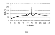
- Fig. 5 is a graph showing the temperature change when thermal runaway occurs after the battery pack of the present invention is used. Firstly, it is slowly heated by the heating piece set in the battery box to simulate the thermal runaway process of the battery pack. When the temperature reaches 70 ° C or higher, the temperature of the battery module reaches 100 ° C or higher, which causes local thermal runaway and the temperature rises sharply. At this time, the hydrofluoroether undergoes a phase change and absorbs heat, so that the temperature of the battery module 2 drops below 100 ° C in about 75 minutes, indicating that the thermal runaway has been controlled, and the spreading tendency is also suppressed.
- the barrier liquid is immiscible with the cooling liquid, the density is less than the density of the cooling liquid, and the barrier liquid does not vaporize below 150 °C.
- the density difference between the liquid and the barrier liquid is greater than 0.3 kg/L.
- the liquid sealing layer containing the barrier liquid is covered on the cooling liquid, and the blocking liquid is not miscible with the cooling liquid, is not volatile, and functions as a liquid seal, which can effectively prevent or slow down the evaporation of the cooling liquid.
- the thickness of the barrier fluid layer is greater than 0.5 mm.
- the barrier liquid is at least one selected from the group consisting of silicone oil and transformer oil; more preferably, the barrier liquid is silicone oil.
- Figure 6 shows a comparison of hydrofluoroether in the absence of a silicone oil seal and a silicone oil seal. After the hydrofluoroether is covered with a silicone oil seal, the hydrofluoroether in the battery compartment is kept for 60 days. There was still no large amount of volatilization, which proved that the silicone oil seal layer played a good liquid sealing effect.
- the battery module is placed upside down in the inner battery case such that the tabs of the battery module are submerged in the blocking liquid.
- Inverted placement of the cells means that the cells are turned upside down so that the electrodes can be immersed in the blocking solution even when less blocking solution is used.
- the amount of heat generated by the ear is relatively large, and immersing it in the blocking liquid is more advantageous for heat dissipation, and is also advantageous for insulation of the battery module.
- the position of the polar ear is relatively easy to break the position, the active material inside the battery is easier to flow out from the break, the battery can be inverted to avoid leakage of the exposed substance in the air, once the leak occurs , so that it quickly flows into the blocking liquid, improving safety performance.
- a breathing valve is provided on the battery case.
- the breathing valve is arranged on the battery box to balance the internal pressure of the battery box and the external atmospheric pressure in time to prevent the box from being subjected to excessive positive or negative pressure when the battery temperature changes.
- the present invention also provides a battery pack system comprising the battery pack as described above, the battery pack system further comprising an external circulation system, the external circulation system being in communication with the battery case through a circulation line, the cooling in the battery case The liquid is circulated through the external circulation system.
- the external circulation system includes a circulation pump, a heat exchanger, a buffer tank, and a circulation line, and the battery box, the circulation pump, the heat exchanger, and the buffer tank are connected by a circulation line.
- the buffer tank is of an open structure, and a coolant is disposed in the buffer tank, and the coolant is covered with a liquid seal layer containing a barrier liquid.
- the open-structure buffer tank can buffer the volume change of the coolant and the barrier liquid caused by changes in temperature, and the structure is simple and effective.
- the invention adopts the method of adding a cooling liquid in the module, utilizes the characteristic that the cooling liquid can boil rapidly and vaporize at a certain temperature, and quickly removes the heat generated by the thermal runaway of some single cells, thereby avoiding the high temperature spreading to the peripheral battery, thereby preventing the high temperature from spreading to the peripheral battery.
- the utility model has the functions of protecting the safety of the battery pack; and covering the cooling liquid with a non-volatile barrier liquid, thereby playing a better sealing function and avoiding the evaporation of the cooling liquid in the battery system; the method has the advantages of simple structure and easy industrialization. And have better security.
- FIG. 1 is a schematic structural view of a battery pack disclosed by the present invention
- FIG. 2 is a schematic structural view of another battery pack disclosed by the present invention.
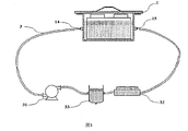
- FIG. 3 is a schematic structural view of a battery pack system disclosed by the present invention.
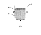
- FIG. 4 is a schematic structural view of a buffer tank disclosed by the present invention.
- the present invention discloses a battery pack including a battery module 2, a coolant 11 and a battery case 1.
- the internal pressure of the battery case 1 is normal pressure.
- the battery module 2 is composed of a single battery and is housed in the battery case 1, while the cooling liquid 11 is added, so that the battery module 2 is immersed in the cooling liquid 11.
- the barrier liquid is added to form a closed liquid sealing layer 12 on the cooling liquid 11, and the thickness of the liquid sealing layer 12 disposed on the liquid surface of the cooling liquid 11 reaches 0.5 mm, so that the leakage of the cooling liquid 11 can be avoided, and the liquid sealing is performed.
- the role is the role.
- the cooling liquid 11 is a hydrofluoroether and the blocking liquid is a silicone oil.
- the present invention discloses a battery pack including a battery module 2, a coolant 11 and a battery case 1, and the internal pressure of the battery case 1 is 0.2 bar.
- the battery module 2 is composed of a single battery and is housed in the battery case 1, and the battery module 2 is placed upside down in the battery case 1.
- the coolant 11 is added so that the tabs of the battery module 2 are immersed in the coolant 11.
- the barrier liquid is added to form a closed liquid sealing layer 12 on the cooling liquid 11, and the thickness of the liquid sealing layer 12 disposed on the liquid surface of the cooling liquid 11 reaches 1 mm, so that the leakage of the cooling liquid 11 can be avoided, and the liquid sealing is performed. effect.
- a breathing valve 13 is disposed on the battery case 1 to balance the pressure inside and outside the battery case 1.
- the cooling liquid 11 is trimethyl phosphate and the blocking liquid is transformer oil.
- the present invention discloses a battery pack including a battery module 2, a coolant 11 and a battery case 1, and the internal pressure of the battery case 1 is 1.5 bar.
- the battery module 2 is composed of a single battery and is housed in the battery case 1, while the cooling liquid 11 is added, so that the battery module 2 is immersed in the cooling liquid 11.
- the barrier liquid is added to form a closed liquid sealing layer 12 on the cooling liquid 11, and the thickness of the liquid sealing layer 12 disposed on the liquid surface of the cooling liquid 11 reaches 1 mm, so that the leakage of the cooling liquid 11 can be avoided, and the liquid sealing is performed. effect.
- the cooling liquid 11 is a hydrofluoroether and the blocking liquid is a silicone oil.
- the present invention discloses a battery pack including a battery module 2, a coolant 11 and a battery case 1, and the internal pressure of the battery case 1 is 3 bar.
- the battery module 2 is composed of a single battery and is housed in the battery case 1, and the battery module 2 is placed upside down in the battery case 1.
- the coolant 11 is added so that the tabs of the battery module 2 are immersed in the coolant 11.
- the barrier liquid is added to form a closed liquid sealing layer 12 on the cooling liquid 11, and the thickness of the liquid sealing layer 12 disposed on the liquid surface of the cooling liquid 11 reaches 1.5 mm, so that the leakage of the cooling liquid 11 can be avoided, and the liquid sealing is performed. The role.
- a breathing valve 13 is disposed on the battery case 1 to balance the pressure inside and outside the battery case 1.
- the coolant 11 is chloroform and the barrier fluid is transformer oil.
- the present invention discloses a battery pack including a battery module 2, a coolant 11 and a battery case 1, and the internal pressure of the battery case 1 is 5 bar.
- the battery module 2 is composed of a single battery and is housed in the battery case 1, and the battery module 2 is placed upside down in the battery case 1.
- the coolant 11 is added so that the tabs of the battery module 2 are immersed in the coolant 11.
- the barrier liquid is added to form a closed liquid sealing layer 12 on the cooling liquid 11, and the thickness of the liquid sealing layer 12 disposed on the liquid surface of the cooling liquid 11 reaches 1 mm, so that the leakage of the cooling liquid 11 can be avoided, and the liquid sealing is performed. effect.
- a breathing valve 13 is disposed on the battery case 1 to balance the pressure inside and outside the battery case 1.
- the coolant 11 is chloroform and the barrier 12 is transformer oil.
- the present invention discloses a battery pack system including the battery pack of FIG. 1.
- the battery pack includes a battery module 2, a coolant 11 and a battery case 1, and the internal pressure of the battery case 1 is 3 bar.
- the battery module 2 is composed of a single battery and is housed in the battery case 1, while the cooling liquid 11 is added, so that the battery module 2 is immersed in the cooling liquid 11.
- the barrier liquid is added to form a closed liquid sealing layer 12 on the cooling liquid 11, and the thickness of the liquid sealing layer 12 disposed on the upper layer of the cooling liquid 11 is 2 mm, so that the leakage of the cooling liquid 11 can be prevented from leaking and the liquid sealing function can be achieved.
- a coolant inlet 14 and a coolant outlet 15 are disposed on the battery case 1, and the battery case 1, the circulation pump 31, the heat exchanger 32, and the buffer tank 33 of the diaphragm type closed structure are connected together through the circulation line 3, and the coolant 11 is
- the coolant inlet 14 of the battery case 1 enters and flows out from the cooling outlet 15.
- the coolant 11 is cooled or warmed by the circulation line 3, the circulation pump 31, the heat exchanger, and the like 32.
- the buffer tank 33 has an open structure, and a coolant 11 is provided in the buffer tank 33, and the liquid seal layer 12 is covered on the coolant 11.
- the coolant 11 is chloroform and the barrier fluid is transformer oil.
Abstract
一种电池组,涉及电池领域,该电池组包括电池模块(2)、冷却液(11)和电池箱(1),所述电池模块(2)和冷却液(11)均设置在电池箱(1)内,所述电池模块(2)至少部分浸入冷却液(11)中,所述冷却液(11)上覆盖包含阻隔液的液封层(12),依靠冷却液的汽化潜热把热失控电池所释放的热量迅速带走,从而避免热量积聚导致电池热失控不断蔓延,起到保护电池组安全的作用。
Description
本发明涉及一种具有控制热失控蔓延的电池组。
锂离子电池因其高比能量、高电压、自放电率低和循环寿命长等优点而被广泛应用于电动汽车中。但由于锂离子电池的安全性存在一定的隐患,当电池组中部分锂离子电池单元由于内部短路、外部短路、过充或者机械破坏等原因,可能导致其温度失控,产生100~700℃的高温和大量热量。
导致热失控的热量来源主要包括电池本身所存储的电能转化和负极材料在80~400℃下分解、正极材料在150~400℃下分解、电解液在200~400℃下分解以及电解液等在高温下燃烧时所释放的热量。这些热量会进一步加热周边的电池,当周边电池被加热到一定程度时(例如130℃),所使用的隔膜开始收缩,导致正负极极片在电池内部直接短路,导致周边电池也发生热失控,从而释放更多热量,最终导致热失控加速蔓延,使得整个电池组失控,严重时引发起火爆炸的安全事故。
申请号为CN201210317186.4,名称为阻燃防爆电池组的专利中,使用了硅油等绝缘液体将电池组部分浸没在其中,这很好地隔绝了空气,减少了热失控时起火的可能性。但是当个别电池热失控发生后,所产生的热量会不断加热绝缘的硅油,使得其温度上升到200℃以上。高温的硅油成为一个加热源,导致周围更多电池的被加热而发生热失控。
发明内容
为解决上述问题,本发明公开了一种电池组,包括电池模块、冷却液和电池箱,所述电池模块和冷却液均设置在电池箱内,所述电池模块至少部分浸入冷却液中,所述冷却液的汽化起始温度在70℃至200℃之间,所述冷却液上覆盖包含阻隔液的液封层,所述阻隔液与冷却液不互溶,密度小于冷却液的密度,并且阻隔液在200℃以下不会汽化。
电池模块至少部分浸入冷却液中,使得电池组产生的热量能够通过冷却液冷却,并且将电池组与空气隔绝,减少热失控时电池出现起火的可能性。
正常工作情况下,电池组可以采用被动的方式散热,电池工作产生的热量通过冷却液传导至电池箱外壳。
当出现热失控时,冷却液可迅速汽化,利用其较高的汽化潜热,带走热失控产生的热量,从而延缓或者避免热失控的蔓延。
冷却液覆盖阻隔液层可以起到液封的作用,阻隔液不易挥发或者不挥发,密度较冷却液低,且二者不互溶。阻隔液浮于冷却液之上,可避免冷却液在正常工作状态时的挥发损失。
本发明中,冷却液的汽化起始温度指的是冷却液发生沸腾后开始大量汽化的温度。
作为本发明的优选,所述冷却液包含具备阻燃、绝缘及抗电解性能的液体。
根据本发明的目的,所述冷却液选自处于电池组的工作压力条件下,汽化起始温度在70℃至150℃之间的液体。
作为本发明的优选,所述冷却液选自处于电池组的工作压力条件下,汽化起始温度在70℃~130℃之间的液体。
作为本发明的优选,所述电池组的工作压力处于0.2bar~5bar之间。
所述冷却液具备阻燃性和绝缘性,在所使用的电位下不会被电解,并且在设定温度热失控温度以上范围内会沸腾。其他情况下,该冷却液同时与单体电池进行热交换,协助电池的加热或者冷却。
当部分单体电池发生热失控而产生高温时,该冷却液能够迅速沸腾汽化。由于通常情况下汽化传热的速率要远高于液体的传导和对流,且液体的汽化潜热要远高于液体的显热,因此利用该液体较高的汽化潜热和汽化导热速度,把热失控电池释放的热量迅速、充分地带走,把电池模块的温度控制在较低的水平(例如低于热失控的温度),避免热量蔓延到更多电池。
电池模块可以设计为负压下工作、常压下工作或者正压下工作。绝对压力范围可以在0.2bar~5bar,对应所使用的压力环境,冷却液的汽化温度选择在70~150℃范围。冷却液在标准大气压下的汽化潜热在25~2500kJ/kg。电池模块若设定于常压工作,选择常压下沸点在70~130℃范围的绝缘液体。
作为本发明的优选,所述冷却液选自三氯甲烷和氢氟醚中的至少一种。
根据本发明的另一种实施方式,所述冷却液选自磷酸三甲酯和磷酸三丙脂中的至少一种。
三氯甲烷、氢氟醚、磷酸三甲酯和磷酸三丙脂具备较低的挥发温度,同时绝缘、阻燃和抗电解的性能较好。
图5显示了采用了本发明中的电池组后,发生热失控时的温度变化曲线。首先通过设置在电池箱中的加热片进行缓慢加热,模拟电池组的热失控过程,直至70~75min时,电池模块的温度达到100℃以上,进而引发局部热失控,温度急剧升高。此时氢氟醚发生相变并吸收热量,使得电池模块2的温度在75min左右降至100℃以下,表明热失控已经得到控制,蔓延的趋势也被压制。
作为本发明的优选,所述阻隔液与冷却液不互溶,密度小于冷却液的密度,并且阻隔液在150℃以下不会气化。
优选地,所述却液与阻隔液的密度差大于0.3kg/L。
由于所选冷却液具有一定的挥发性。在非密闭系统中使用时,冷却液可能因不断挥发而漏失。在冷却液上覆盖包含阻隔液的液封层,并且该阻隔液与冷却液不互溶,不易挥发性,起到了液封的作用,可有效阻止或者减缓冷却液的挥发。
作为本发明的优选,阻隔液层的厚度大于0.5mm。
作为本发明的优选,所述阻隔液选自硅油和变压器油中的至少一种;更优选地,所述阻隔液为硅油。
图6显示了氢氟醚在没有使用硅油液封层和使用了硅油液封层的对比,氢氟醚上覆盖了硅油液封层之后,尽管搁置了60天,但是电池箱内的氢氟醚仍然没有出现大量挥发的情况,证明硅油液封层起到了很好的液封作用。
作为优选,所述电池模块在电池内箱内倒置放置,使得所述电池模块的极耳浸没在封闭液中。
单体电池倒置放置,是指将单体电池极耳朝下,如此可以在使用较少的封闭液时也能把电极浸入封闭液中。对于单体电池来说极耳的发热量相对较大,将其浸入封闭液中更有利于散热,而且也有利于电池模块的绝缘。
对于软包装电池来说,极耳的封装位置是相对容易发生破口的位置,电池内部的活性物质较易从破口处流出,将单体电池倒置可以避免泄漏物质暴露在空气中,一旦发生泄漏,使之迅速流入封闭液中,提升了安全性能。
作为本发明的优选,所述电池箱上设置呼吸阀。
电池箱上设置呼吸阀可以及时地平衡电池箱的内压和外界大气压,防止在电池温度变化时,箱体承受过大的正压或者负压。
本发明还提供了一种电池组系统,包括如上所述电池组,所述电池组系统还包括外部循环系统,所述外部循环系统通过循环管路与电池箱连通,所述电池箱中的冷却液通过外部循环系统进行循环。
根据本发明的一种实施方式,所述外部循环系统包括循环泵、换热器、缓冲罐以及循环管路,所述电池箱、循环泵、换热器和缓冲罐通过循环管路连接。
作为本发明优选的另一种实施方式,所述缓冲罐是开放结构,所述缓冲罐内设置冷却液,所述冷却液上覆盖包含阻隔液的液封层。
开放结构的缓冲罐可以对温度等变化引起的冷却液及阻隔液的体积变化起到缓冲作用,结构简单有效。
本发明通过在模块中加入冷却液的方法,利用冷却液在一定温度下能够沸腾迅速汽化的特性,把部分单体电池热失控所产生的热量迅速带走,避免了高温蔓延到周边电池,从而起到保护电池组安全的作用;并且在冷却液上覆盖一层不易挥发的阻隔液,起到了较好的封闭作用,避免冷却液在电池系统中的挥发散失;该方法结构简单,易于工业化实现,而且具有更好的安全性。
图1是本发明公开的一种电池组的结构示意图;
图2是本发明公开的另一种电池组的结构示意图;
图3是本发明公开的一种电池组系统的结构示意图;
图4是本发明公开的一种缓冲罐的结构示意图;
图5是本发明公开的一种电池组热失控的模拟温度变化曲线;
图6是本发明公开的电池组在有硅油覆盖和无硅油覆盖时,冷却液在搁置60天后的挥发散失对比数据;
其中,1.电池箱,11.冷却液,12.液封层,13.呼吸阀,14.冷却液进口,15.冷却液出口,2.电池模块,3.循环管路,31.循环泵,32.换热器,33.缓冲罐。
以下的具体实施例对本发明进行了详细的描述,然而本发明并不限制于以下实施例。
实施例1:
如图1所示,本发明公开一种电池组,包括电池模块2、冷却液11和电池箱1,电池箱1的内压为常压。电池模块2由单体电池组成,并装入电池箱1中,同时加入冷却液11,使得电池模块2浸入冷却液11中。然后加入阻隔液使得冷却液11上形成封闭的液封层12,设置于冷却液11液面之上的液封层12的厚度达到0.5mm,如此可避免冷却液11挥发泄漏,起到液封的作用。
该实施例中冷却液11是氢氟醚,阻隔液是硅油。
实施例2:
如图2所示,本发明公开一种电池组,包括电池模块2、冷却液11和电池箱1,电池箱1的内压为0.2bar。电池模块2由单体电池组成,并装入电池箱1中,电池模块2在电池箱1内倒置放置。
同时加入冷却液11,使得电池模块2的极耳浸入冷却液11中。然后加入阻隔液使得冷却液11上形成封闭的液封层12,设置于冷却液11液面之上的液封层12的厚度达到1mm,如此可避免冷却液11挥发泄漏,起到液封的作用。
电池箱1上设置一个呼吸阀13,平衡电池箱1内外压力。
该实施例中冷却液11是磷酸三甲酯,阻隔液是变压器油。
实施例3:
如图1所示,本发明公开一种电池组,包括电池模块2、冷却液11和电池箱1,电池箱1的内压为1.5bar。电池模块2由单体电池组成,并装入电池箱1中,同时加入冷却液11,使得电池模块2浸入冷却液11中。然后加入阻隔液使得冷却液11上形成封闭的液封层12,设置于冷却液11液面之上的液封层12的厚度达到1mm,如此可避免冷却液11挥发泄漏,起到液封的作用。
该实施例中冷却液11是氢氟醚,阻隔液是硅油。
实施例4:
如图2所示,本发明公开一种电池组,包括电池模块2、冷却液11和电池箱1,电池箱1的内压为3bar。电池模块2由单体电池组成,并装入电池箱1中,电池模块2在电池箱1内倒置放置。
同时加入冷却液11,使得电池模块2的极耳浸入冷却液11中。然后加入阻隔液使得冷却液11上形成封闭的液封层12,设置于冷却液11液面之上的液封层12的厚度达到1.5mm,如此可避免冷却液11挥发泄漏,起到液封的作用。
电池箱1上设置一个呼吸阀13,平衡电池箱1内外压力。
该实施例中冷却液11是三氯甲烷,阻隔液是变压器油。
实施例5:
如图2所示,本发明公开一种电池组,包括电池模块2、冷却液11和电池箱1,电池箱1的内压为5bar。电池模块2由单体电池组成,并装入电池箱1中,电池模块2在电池箱1内倒置放置。
同时加入冷却液11,使得电池模块2的极耳浸入冷却液11中。然后加入阻隔液使得冷却液11上形成封闭的液封层12,设置于冷却液11液面之上的液封层12的厚度达到1mm,如此可避免冷却液11挥发泄漏,起到液封的作用。
电池箱1上设置一个呼吸阀13,平衡电池箱1内外压力。
该实施例中冷却液11是三氯甲烷,阻隔液12是变压器油。
实施例6:
如图3所示,本发明公开一种电池组系统,包括图1中的电池组,电池组包括电池模块2、冷却液11和电池箱1,电池箱1的内压为3bar。电池模块2由单体电池组成,并装入电池箱1中,同时加入冷却液11,使得电池模块2浸入冷却液11中。然后加入阻隔液使得冷却液11上形成封闭的液封层12,设置于冷却液11上层的液封层12的厚度达到2mm,如此可避免冷却液11挥发泄漏,起到液封的作用。
在电池箱1上设置冷却液进口14和冷却液出口15,电池箱1、循环泵31、换热器32和隔膜式密闭结构的缓冲罐33通过循环管路3连接在一起,冷却液11从电池箱1的冷却液进口14进入,从冷却出口15流出。冷却液11通过循环管路3、循环泵31、换热器等32实现降温或者加温。
如图4所示,该缓冲罐33为开放结构,缓冲罐33内设置冷却液11,并在冷却液11上覆盖液封层12。
该实施例中冷却液11是三氯甲烷,阻隔液是变压器油。
Claims (14)
- 一种电池组,包括电池模块、冷却液和电池箱,所述电池模块和冷却液均设置在电池箱内,所述电池模块至少部分浸入冷却液中,其特征在于:所述冷却液的汽化起始温度在70℃至200℃之间,所述冷却液上覆盖包含阻隔液的液封层,所述阻隔液与冷却液不互溶,密度小于冷却液的密度,并且阻隔液在200℃以下不会汽化。
- 如权利要求1所述的电池组,其特征在于:所述冷却液包含具备阻燃、绝缘及抗电解性能的液体。
- 如权利要求2所述的电池组,其特征在于:所述冷却液的汽化起始温度在70℃至150℃之间。
- 如权利要求3所述的电池组,其特征在于:所述冷却液的汽化起始温度在70℃~130℃之间。
- 如权利要求4所述的电池组,其特征在于:所述冷却液选自三氯甲烷和氢氟醚中的至少一种。
- 如权利要求1所述的电池组,其特征在于:所述冷却液选自磷酸三甲酯和磷酸三丙脂中的至少一种。
- 如权利要求1所述的电池组,其特征在于:所述阻隔液在150℃以下不会气化。
- 如权利要求1所述的电池组,其特征在于:所述冷却液与阻隔液的密度差大于0.3kg/L。
- 如权利要求1所述的电池组,其特征在于:所述液封层的厚度大于0.5mm。
- 如权利要求1所述的电池组,其特征在于:所述阻隔液选自硅油和变压器油中的至少一种。
- 如权利要求1所述的电池组,其特征在于:所述电池箱上设置呼吸阀。
- 一种电池组系统,包括权利要求1所述的电池组,其特征在于:所述电池组系统还包括外部循环系统,所述外部循环系统通过循环管路与电池箱连通,所述电池箱中的冷却液通过外部循环系统进行循环。
- 如权利要求12所述电池组系统,其特征在于:所述外部循环系统包括循环泵、换热器、缓冲罐以及循环管路,所述电池箱、循环泵、换热器和缓冲罐通过循环管路连接。
- 如权利要求13所述电池组系统,其特征在于:所述缓冲罐是开放结构,所述缓冲罐内设置冷却液,所述冷却液上覆盖包含阻隔液的液封层。
Priority Applications (4)
| Application Number | Priority Date | Filing Date | Title |
|---|---|---|---|
| US15/751,873 US10790559B2 (en) | 2015-08-14 | 2015-08-14 | Battery pack and battery pack system |
| CN201580082297.3A CN107851864B (zh) | 2015-08-14 | 2015-08-14 | 电池组 |
| EP15901238.4A EP3322015B1 (en) | 2015-08-14 | 2015-08-14 | Battery |
| PCT/CN2015/087039 WO2017028033A1 (zh) | 2015-08-14 | 2015-08-14 | 电池组 |
Applications Claiming Priority (1)
| Application Number | Priority Date | Filing Date | Title |
|---|---|---|---|
| PCT/CN2015/087039 WO2017028033A1 (zh) | 2015-08-14 | 2015-08-14 | 电池组 |
Publications (1)
| Publication Number | Publication Date |
|---|---|
| WO2017028033A1 true WO2017028033A1 (zh) | 2017-02-23 |
Family
ID=58050512
Family Applications (1)
| Application Number | Title | Priority Date | Filing Date |
|---|---|---|---|
| PCT/CN2015/087039 WO2017028033A1 (zh) | 2015-08-14 | 2015-08-14 | 电池组 |
Country Status (4)
| Country | Link |
|---|---|
| US (1) | US10790559B2 (zh) |
| EP (1) | EP3322015B1 (zh) |
| CN (1) | CN107851864B (zh) |
| WO (1) | WO2017028033A1 (zh) |
Cited By (4)
| Publication number | Priority date | Publication date | Assignee | Title |
|---|---|---|---|---|
| EP3331060A4 (en) * | 2016-03-16 | 2018-06-13 | LG Chem, Ltd. | Battery module |
| EP3477764A1 (en) * | 2017-10-27 | 2019-05-01 | ABB Schweiz AG | Battery energy storage system with two-phase cooling |
| CN110770964A (zh) * | 2017-03-09 | 2020-02-07 | 祖达汽车有限公司 | 热调节系统和方法 |
| CN117317460A (zh) * | 2023-09-20 | 2023-12-29 | 武汉理工大学 | 一种电池热管理与热失控抑制一体化装置及控制方法 |
Families Citing this family (34)
| Publication number | Priority date | Publication date | Assignee | Title |
|---|---|---|---|---|
| US11501917B2 (en) * | 2018-03-02 | 2022-11-15 | Capacitor Foundry Llc | Capacitors employing dielectric material outside volume enclosed by electrodes |
| CN108736079A (zh) * | 2018-04-08 | 2018-11-02 | 江西优特汽车技术有限公司 | 一种动力电池热失控扩散预警系统及方法 |
| FR3084210B1 (fr) * | 2018-07-19 | 2020-06-19 | Renault S.A.S. | Ensemble comportant un dispositif de refroidissement par changement de phase |
| CN109841918A (zh) * | 2019-03-01 | 2019-06-04 | 华南理工大学 | 利用浸没式冷却散热的电动汽车动力电池组散热结构 |
| JP7228715B2 (ja) * | 2019-04-15 | 2023-02-24 | ロベルト・ボッシュ・ゲゼルシャフト・ミト・ベシュレンクテル・ハフツング | 補償デバイスを含む圧力管理システムを有する電池パック |
| CN113966561A (zh) | 2019-04-15 | 2022-01-21 | 罗伯特·博世有限公司 | 用于电池包的压力管理装置 |
| CN114144929A (zh) * | 2019-04-15 | 2022-03-04 | 罗伯特·博世有限公司 | 具有压力管理系统的电池包 |
| CN113994524A (zh) * | 2019-04-15 | 2022-01-28 | 罗伯特·博世有限公司 | 具有热管理系统的电池包 |
| EP3742541A1 (en) * | 2019-05-21 | 2020-11-25 | 3M Innovative Properties Company | Thermal management system for battery cells |
| FR3098647B1 (fr) * | 2019-07-08 | 2024-04-05 | Psa Automobiles Sa | Bloc de batterie |
| CN110611139B (zh) * | 2019-09-24 | 2024-03-22 | 浙江南都电源动力股份有限公司 | 一种用于换电柜的持续降温系统 |
| CN111081930A (zh) * | 2019-11-29 | 2020-04-28 | 诚拓(洛阳)新能源科技有限公司 | 一种防火锂离子电池模块 |
| FR3104893B1 (fr) * | 2019-12-12 | 2022-01-07 | Valeo Systemes Thermiques | « Dispositif de régulation thermique d’au moins un composant électrique » |
| US11949083B2 (en) * | 2020-06-11 | 2024-04-02 | Global Graphene Group, Inc. | Battery module or pack with a distributed cooling and fire protection system and method of operating same |
| CN112002954B (zh) * | 2020-07-14 | 2022-08-30 | 安徽汉马锂电科技有限公司 | 一种液体浸没冷却式动力电池组 |
| US11742539B2 (en) | 2020-09-04 | 2023-08-29 | Romeo Power, Inc. | Systems and methods for battery tab cooling |
| KR20220039909A (ko) * | 2020-09-21 | 2022-03-30 | 주식회사 엘지에너지솔루션 | 전력 저장 장치 |
| US11916211B2 (en) * | 2020-09-28 | 2024-02-27 | Hamilton Sundstrand Corporation | Extinguishing battery thermal runaway |
| US20220096885A1 (en) * | 2020-09-28 | 2022-03-31 | Hamilton Sundstrand Corporation | Extinguishing battery thermal runaway |
| CN112652836A (zh) * | 2020-12-16 | 2021-04-13 | 杭州科技职业技术学院 | 一种新能源汽车专用电池散热装置 |
| EP4264729A2 (en) * | 2020-12-21 | 2023-10-25 | Phase Motion Control S.p.A. | Battery pack comprising one or more cells and a battery management system for monitoring and controlling the cells |
| WO2022137117A1 (en) * | 2020-12-21 | 2022-06-30 | Phase Motion Control S.P.A. | Battery pack comprising one or more electrochemical cells and a plurality of electronic control boards |
| GB2603475A (en) * | 2021-02-01 | 2022-08-10 | Aston Martin Lagonda Ltd | Battery assembly for a vehicle |
| EP4117086A1 (en) | 2021-07-07 | 2023-01-11 | Lanxess Corporation | Phosphate ester heat transfer fluids for immersion cooling system |
| EP4116391A1 (en) | 2021-07-07 | 2023-01-11 | Lanxess Corporation | Phosphate ester heat transfer fluids and their use in an immersion cooling system |
| EP4117087A1 (en) | 2021-07-07 | 2023-01-11 | Lanxess Corporation | Phosphate ester heat transfer fluids for immersion cooling system |
| WO2023283117A1 (en) | 2021-07-07 | 2023-01-12 | Lanxess Corporation | Phosphate ester heat transfer fluids and their use in an immersion cooling system |
| WO2023283120A1 (en) | 2021-07-07 | 2023-01-12 | Lanxess Corporation | Phosphate ester heat transfer fluids for immersion cooling system |
| WO2023283115A1 (en) | 2021-07-07 | 2023-01-12 | Lanxess Corporation | Phosphate ester heat transfer fluids for immersion cooling system |
| CN115707217A (zh) * | 2021-08-12 | 2023-02-17 | 富联精密电子(天津)有限公司 | 一种强化冷凝传热的两相浸没式冷却装置 |
| US20230088026A1 (en) * | 2021-09-17 | 2023-03-23 | GM Global Technology Operations LLC | System for detection and termination of thermal runaway in battery cells |
| FR3128318A1 (fr) * | 2021-10-15 | 2023-04-21 | Faurecia Systemes D'echappement | Cellule poche et batterie de stockage d’électricité |
| US20230268578A1 (en) * | 2022-02-23 | 2023-08-24 | Baidu Usa Llc | Energy storage cell packaging and system with acceleration design |
| CN114614103B (zh) * | 2022-03-21 | 2024-02-09 | 上海兰钧新能源科技有限公司 | 冷却装置与锂电池冷却降温系统 |
Citations (5)
| Publication number | Priority date | Publication date | Assignee | Title |
|---|---|---|---|---|
| CN101542806A (zh) * | 2006-11-24 | 2009-09-23 | 丰田自动车株式会社 | 电源系统 |
| CN201466117U (zh) * | 2009-07-24 | 2010-05-12 | 岑显荣 | 一种带冷却外壳的电动汽车蓄电池及其冷却装置 |
| US20120003515A1 (en) * | 2010-06-30 | 2012-01-05 | Nissan Technical Center North America, Inc. | Vehicle battery temperature control system and method |
| CN103682511A (zh) * | 2012-09-13 | 2014-03-26 | 微宏动力系统(湖州)有限公司 | 电动汽车 |
| CN103996886A (zh) * | 2013-02-19 | 2014-08-20 | 微宏动力系统(湖州)有限公司 | 具备散热能力的电池模块 |
Family Cites Families (7)
| Publication number | Priority date | Publication date | Assignee | Title |
|---|---|---|---|---|
| JP4134359B2 (ja) | 1997-07-17 | 2008-08-20 | 株式会社デンソー | 電池冷却装置 |
| US20090176148A1 (en) * | 2008-01-04 | 2009-07-09 | 3M Innovative Properties Company | Thermal management of electrochemical cells |
| JP2010146883A (ja) | 2008-12-19 | 2010-07-01 | Toyota Motor Corp | 蓄電装置 |
| US10454078B2 (en) * | 2012-08-30 | 2019-10-22 | The Chemours Company Fc, Llc | Li-ion battery having improved safety against combustion |
| CN103682188B (zh) | 2012-08-31 | 2016-08-31 | 微宏动力系统(湖州)有限公司 | 阻燃防爆电池组 |
| JP2014060088A (ja) * | 2012-09-19 | 2014-04-03 | Toshiba Corp | 二次電池装置および二次電池システム |
| US9379419B2 (en) * | 2013-05-13 | 2016-06-28 | The Boeing Company | Active thermal management and thermal runaway prevention for high energy density lithium ion battery packs |
-
2015
- 2015-08-14 CN CN201580082297.3A patent/CN107851864B/zh active Active
- 2015-08-14 WO PCT/CN2015/087039 patent/WO2017028033A1/zh active Application Filing
- 2015-08-14 US US15/751,873 patent/US10790559B2/en active Active
- 2015-08-14 EP EP15901238.4A patent/EP3322015B1/en active Active
Patent Citations (5)
| Publication number | Priority date | Publication date | Assignee | Title |
|---|---|---|---|---|
| CN101542806A (zh) * | 2006-11-24 | 2009-09-23 | 丰田自动车株式会社 | 电源系统 |
| CN201466117U (zh) * | 2009-07-24 | 2010-05-12 | 岑显荣 | 一种带冷却外壳的电动汽车蓄电池及其冷却装置 |
| US20120003515A1 (en) * | 2010-06-30 | 2012-01-05 | Nissan Technical Center North America, Inc. | Vehicle battery temperature control system and method |
| CN103682511A (zh) * | 2012-09-13 | 2014-03-26 | 微宏动力系统(湖州)有限公司 | 电动汽车 |
| CN103996886A (zh) * | 2013-02-19 | 2014-08-20 | 微宏动力系统(湖州)有限公司 | 具备散热能力的电池模块 |
Non-Patent Citations (1)
| Title |
|---|
| See also references of EP3322015A4 * |
Cited By (9)
| Publication number | Priority date | Publication date | Assignee | Title |
|---|---|---|---|---|
| EP3331060A4 (en) * | 2016-03-16 | 2018-06-13 | LG Chem, Ltd. | Battery module |
| US10601089B2 (en) | 2016-03-16 | 2020-03-24 | Lg Chem, Ltd. | Battery module |
| CN110770964A (zh) * | 2017-03-09 | 2020-02-07 | 祖达汽车有限公司 | 热调节系统和方法 |
| EP3593400A4 (en) * | 2017-03-09 | 2021-03-31 | Zuta-Car Systems Ltd | THERMAL REGULATION SYSTEMS AND PROCESSES |
| US11462786B2 (en) | 2017-03-09 | 2022-10-04 | Zuta-Car Ltd. | Systems and methods for thermal regulation |
| IL269230B1 (en) * | 2017-03-09 | 2023-05-01 | Zuta Car Ltd | Thermal regulation systems and methods |
| IL269230B2 (en) * | 2017-03-09 | 2023-09-01 | Zuta Car Ltd | Thermal regulation systems and methods |
| EP3477764A1 (en) * | 2017-10-27 | 2019-05-01 | ABB Schweiz AG | Battery energy storage system with two-phase cooling |
| CN117317460A (zh) * | 2023-09-20 | 2023-12-29 | 武汉理工大学 | 一种电池热管理与热失控抑制一体化装置及控制方法 |
Also Published As
| Publication number | Publication date |
|---|---|
| EP3322015B1 (en) | 2020-06-03 |
| CN107851864B (zh) | 2020-10-30 |
| CN107851864A (zh) | 2018-03-27 |
| EP3322015A4 (en) | 2018-06-13 |
| US20180233791A1 (en) | 2018-08-16 |
| US10790559B2 (en) | 2020-09-29 |
| EP3322015A1 (en) | 2018-05-16 |
Similar Documents
| Publication | Publication Date | Title |
|---|---|---|
| WO2017028033A1 (zh) | 电池组 | |
| Yang et al. | Thermal self‐protection of zinc‐ion batteries enabled by smart hygroscopic hydrogel electrolytes | |
| EP3306737B1 (en) | Battery pack and battery pack system | |
| EP2997623B1 (en) | Active thermal management and thermal runaway prevention for high energy density lithium ion battery packs | |
| WO2017152843A1 (zh) | 一种电池系统、具有该电池系统的电动汽车及储能系统 | |
| CN105977521B (zh) | 一种高安全性锂离子电池 | |
| CN107851861B (zh) | 一种电池组 | |
| JP7403857B2 (ja) | 電気化学蓄電デバイスの熱管理 | |
| BR112016029997B1 (pt) | Módulo de bateria, método de gestão de um evento de combustão em um módulo de bateria e sistema de energia | |
| CN107134605A (zh) | 一种蒸发冷却阻燃电池系统 | |
| KR20100057691A (ko) | 온도 조절식 배터리 장치 및 이를 위한 방법 | |
| BR112013006171B1 (pt) | Acumulador de lítio | |
| KR20120139970A (ko) | 안전장치가 구비된 배터리 | |
| CN205335394U (zh) | 带有冷却装置的电池组 | |
| CN210723159U (zh) | 一种灭火动力电池模组及电池包 | |
| JP2015198087A (ja) | 多重セル電池パック、および多重セル電池パックの熱の除去方法 | |
| CN112563620A (zh) | 一种可有效防止热失控的锂电池储能系统 | |
| CN206225492U (zh) | 一种高低温可控的动力锂离子电池装置 | |
| CN205811014U (zh) | 一种锂电池阻燃装置 | |
| CN204706599U (zh) | 隔膜锂电池 | |
| CN214043784U (zh) | 一种可有效防止热失控的锂电池储能系统 | |
| CN207426066U (zh) | 一种阻燃电池系统 | |
| CN209675356U (zh) | 电池装置 | |
| CN217114532U (zh) | 一种大容量电池壳体结构 | |
| CN206947473U (zh) | 一种蒸发冷却阻燃电池系统 |
Legal Events
| Date | Code | Title | Description |
|---|---|---|---|
| 121 | Ep: the epo has been informed by wipo that ep was designated in this application |
Ref document number: 15901238 Country of ref document: EP Kind code of ref document: A1 |
|
| WWE | Wipo information: entry into national phase |
Ref document number: 15751873 Country of ref document: US |
|
| NENP | Non-entry into the national phase |
Ref country code: DE |
|
| WWE | Wipo information: entry into national phase |
Ref document number: 2015901238 Country of ref document: EP |