WO2017026205A1 - 測位端末管理システム、測位端末、管理センタ、測位端末管理方法 - Google Patents
測位端末管理システム、測位端末、管理センタ、測位端末管理方法 Download PDFInfo
- Publication number
- WO2017026205A1 WO2017026205A1 PCT/JP2016/069908 JP2016069908W WO2017026205A1 WO 2017026205 A1 WO2017026205 A1 WO 2017026205A1 JP 2016069908 W JP2016069908 W JP 2016069908W WO 2017026205 A1 WO2017026205 A1 WO 2017026205A1
- Authority
- WO
- WIPO (PCT)
- Prior art keywords
- positioning
- terminal
- control mode
- power control
- terminals
- Prior art date
- Legal status (The legal status is an assumption and is not a legal conclusion. Google has not performed a legal analysis and makes no representation as to the accuracy of the status listed.)
- Ceased
Links
Images


Classifications
-
- G—PHYSICS
- G06—COMPUTING OR CALCULATING; COUNTING
- G06F—ELECTRIC DIGITAL DATA PROCESSING
- G06F1/00—Details not covered by groups G06F3/00 - G06F13/00 and G06F21/00
- G06F1/26—Power supply means, e.g. regulation thereof
- G06F1/32—Means for saving power
-
- G—PHYSICS
- G08—SIGNALLING
- G08G—TRAFFIC CONTROL SYSTEMS
- G08G1/00—Traffic control systems for road vehicles
- G08G1/01—Detecting movement of traffic to be counted or controlled
Definitions
- the present invention relates to a positioning terminal management system and a positioning terminal management method for managing power consumption of positioning terminals.
- Patent Document 1 describes a method for performing power management of a positioning terminal.
- the positioning terminal described in Patent Document 1 includes a GPS block having a positioning function by GPS, and a terminal device block that executes various functions of the terminal.
- the positioning terminal described in Patent Document 1 supplies power only to the GPS block during cold start or warm start, and restricts power supply to the terminal device block. Thereby, the power consumption of the positioning terminal is suppressed.
- Patent Document 1 cannot refer to information outside the terminal itself. For this reason, even if there is little information that can be used for power management and power saving is possible, power saving may not be possible.
- an object of the present invention is to provide a positioning terminal management system and a positioning terminal management method capable of managing power according to the situation.
- the positioning terminal management system includes a plurality of positioning terminals and a management unit.
- Each of the plurality of positioning terminals includes a control unit and a positioning signal receiving unit.
- the positioning signal receiving unit receives the positioning signal and calculates the position of the terminal itself.
- the control unit performs power control of the terminal based on the power control mode.
- a management part determines the power supply control mode for every positioning terminal using the position of a some positioning terminal.
- the management unit implements power management for each positioning terminal using the positions of a plurality of positioning terminals. Thereby, in each positioning terminal, power management is executed using not only information in the terminal itself but also information from the outside.
- power management can be performed using information from outside the device itself, and more appropriate power saving for the positioning terminal can be realized.
- FIG. 1 is a vehicle layout diagram for explaining a specific example of setting of a power control mode according to the first embodiment of the present invention.
- the block diagram which shows the structure of the positioning terminal management system which concerns on the 2nd Embodiment of this invention.
- the flowchart which shows the power management flow of the management center of the positioning terminal management system which concerns on the 2nd Embodiment of this invention.
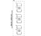
- FIG. 7 is a vehicle layout diagram for explaining a specific example of setting of a power control mode according to the second embodiment of the present invention.
- the flowchart which shows the power management flow of the management center of the positioning terminal management system which concerns on the 3rd Embodiment of this invention.
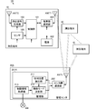
- FIG. 1 is a block diagram showing a configuration of a positioning terminal management system according to the first embodiment of the present invention.
- the positioning terminal management system 1 includes a plurality of positioning terminals 10 and a management center 20.
- the positioning terminal 10 includes a control unit 101, a power source 102, a positioning signal receiving unit 103, a terminal side communication unit 104, a sensor 105, a positioning antenna ANTS, and a communication antenna ANTT. Note that the positioning terminal 10 may or may not include the sensor 105.
- the control unit 101 performs overall control of the positioning terminal 10.
- the control unit 101 performs power control on the positioning signal receiving unit 103, the sensor 105, and the terminal side communication unit 104 in accordance with the power control mode received from the management center 20. A specific power control method will be described later.
- the power supply control mode includes, for example, a power saving mode and a steady mode for maintaining the current power supply.
- the control unit 101 supplies power to all functional units of the positioning terminal 10.
- the control unit 101 stops power supply to some of the plurality of functional units constituting the positioning terminal 10.
- the power saving mode can be divided into a plurality of stages.
- a mode in which power supply to the positioning signal receiving unit 103 is stopped a mode in which power supply to the sensor 105 is stopped, a mode in which power supply to the positioning signal receiving unit 103 and the sensor 105 is stopped, and the terminal side communication unit 104
- a mode in which the communication frequency is lowered and intermittent operation is performed a mode in which power supply to other than the control unit 101 is stopped.
- the power source 102 supplies power to the control unit 101, the positioning signal receiving unit 103, the terminal side communication unit 104, and the sensor 105. At this time, the power source 102 supplies power under power control from the control unit 101.
- the positioning signal receiving unit 103 is connected to the positioning antenna ANTS.
- the positioning signal receiving unit 103 captures and tracks the positioning signal received by the positioning antenna ANTS.
- the positioning signal receiving unit 103 performs positioning by a known method using the tracking positioning signal and calculates the position of the positioning terminal 10.
- the positioning signal receiving unit 103 outputs the calculated position to the control unit 101 and the terminal side communication unit 104.
- the sensor 105 includes at least one of various sensors such as an acceleration sensor, an angular velocity sensor, and a geomagnetic sensor.
- the sensor 105 outputs the sensor measurement value to the control unit 101 and the terminal side communication unit 104. For example, if the sensor 105 is an acceleration sensor, the measured acceleration is output to the control unit 101 and the terminal side communication unit 104.
- the terminal-side communication unit 104 performs data communication with the center-side communication unit 202 of the management center 20 via the communication antenna ANTT.
- the terminal-side communication unit 104 transmits the position of the positioning terminal 10 and the sensor measurement value to the center-side communication unit 202.
- the terminal-side communication unit 104 receives the power control mode transmitted from the center-side communication unit 202 and outputs it to the control unit 101.
- the management center 20 includes a management unit 201, a center side communication unit 202, and a communication antenna ANTt.
- the management unit 201 includes a relative position detection unit 211 and a control mode determination unit 212.
- the relative position detection unit 211 detects the relative positions of the plurality of positioning terminals 10 using the positions of the positioning terminals transmitted from the plurality of positioning terminals 10.
- the relative position detection unit 211 outputs the relative position to the control mode determination unit 212.
- the control mode determination unit 212 determines a power control mode specific to each of the plurality of positioning terminals 10 using the relative positions of the plurality of positioning terminals 10. A specific method for determining the power control mode will be described later.
- the center side communication unit 202 performs data communication with the terminal side communication unit 104 of each positioning terminal 10 through the communication antenna ANTt.
- the center side communication unit 202 receives the position and sensor measurement values transmitted from the terminal side communication unit 104 of each positioning terminal 10 and outputs them to the management unit 201.
- the center side communication unit 202 may output at least the position to the management unit 201.
- the sensor measurement value may be stored in a storage unit (not shown) of the management center 20.
- the center side communication unit 202 transmits the power control mode determined by the management unit 201 to the terminal side communication unit 104 of each positioning terminal 10.
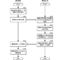
- FIG. 2 is a flowchart showing a power management flow of the positioning terminal management system according to the first embodiment of the present invention.
- the positioning signal receiving unit 103 of the plurality of positioning terminals 10 receives the positioning signal and calculates the position of the own device (S101).
- the terminal side communication unit 104 of the plurality of positioning terminals 10 transmits the position of the own device to the management center 20 (S102).
- the relative position detection unit 211 of the management unit 201 of the management center 20 acquires the positions of the plurality of positioning terminals 10 via the center side communication unit 202 (S201).
- the relative position detector 211 calculates the relative positions of the plurality of positioning terminals 10 based on the acquired positions (S202).
- the control mode determination unit 212 of the management unit 201 determines the power control mode for each positioning terminal 10 from the relative position. For example, the control mode determination unit 212 determines the power control mode based on the condition that there is another positioning terminal 10 within a specific distance in a specific direction with respect to the positioning terminal 10 for which the power control mode is determined.
- the control mode determination unit 212 sets the power control mode of the power saving mode when the target positioning terminal 10 satisfies this condition.
- the control mode determination unit 212 sets the power control mode in the steady mode when the target positioning terminal 10 does not satisfy this condition.
- the control mode determination unit 212 sets the power supply control mode for 10 in all the positioning terminals that have acquired the positions.
- the control units 101 of the plurality of positioning terminals 10 receive the power supply control mode via the terminal side communication unit 104 (S103). Each control unit 101 detects the power control mode set for the terminal from the identification information. The control unit 101 performs power control according to the detected power control mode (S104). For example, when detecting the power control mode of the power saving mode, the control unit 101 stops the positioning signal receiving unit 103 and stops the power supply to the positioning signal receiving unit 103. Further, when detecting the power control mode of the power saving mode, the control unit 101 stops the sensor 105 and stops the power supply to the sensor 105.
- control unit 101 when the control unit 101 detects the power control mode of the power saving mode that requires lower power, the control unit 101 stops the positioning signal receiving unit 103 and the sensor 105 to stop power supply thereto, and the terminal side communication unit The communication frequency of 104 is reduced. Further, when detecting the power control mode of the power saving mode that minimizes the power consumption, the control unit 101 stops the power supply to the functional units other than the control unit 101.
- the positioning terminal 10 can perform power supply control based on not only the position of the own terminal but also the relative position between the own terminal and another terminal. Therefore, the positioning terminal 10 can realize power supply control that accurately conforms to the situation where the terminal is placed, for example, switching to the power saving mode.
- the power control mode is determined using the position of the positioning terminal.
- the power control mode may be determined using a sensor measurement value (for example, direction).
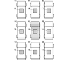
- FIG. 3 is a layout diagram of the vehicle for explaining a specific example of setting of the power control mode according to the first embodiment of the present invention.
- the vehicles 91, 92, 93, 94, 95, 96, 97, 98, 99 are parked in three vertical rows and three horizontal rows.
- the positioning terminal 11 is attached to the vehicle 91
- the positioning terminal 12 is attached to the vehicle 92
- the positioning terminal 13 is attached to the vehicle 93.
- the positioning terminal 14 is attached to the vehicle 94
- the positioning terminal 15 is attached to the vehicle 95
- the positioning terminal 16 is attached to the vehicle 96.
- Positioning terminal 17 is attached to vehicle 97
- positioning terminal 18 is attached to vehicle 98
- positioning terminal 19 is attached to vehicle 99.
- the positioning terminal 11-19 has the same configuration as the positioning terminal 10 described above.
- the management unit 201 acquires the positions of the positioning terminals 11-19 and calculates their relative positions. Specifically, the management unit 201 calculates the azimuth and distance of other positioning terminals with respect to the positioning terminal for which the power control mode is set.
- the management unit 201 determines the relative position of each positioning terminal 11-14, 16-19 with respect to the positioning terminal 15 from the position of the positioning terminal 11-19. Is calculated. Specifically, the management unit 201 calculates the positions and orientations of the positioning terminals 11-14 and 16-19 using the position of the positioning terminal 15 as a reference point.
- the management unit 201 can detect from the calculation results that the positioning terminals 12, 14, 16, and 18 exist in two orthogonal directions with the position of the positioning terminal 15 as a reference point. The management unit 201 detects whether or not these positioning terminals 12, 14, 16, 18 are close to the positioning terminal 15 from the distances of the positioning terminals 12, 14, 16, 18 to the positioning terminal 15. For example, the management unit 201 stores the size of the vehicle 91-99 in advance, the threshold set by the distance of the width, length, or less of the vehicle 91-99, and the positioning terminals 12, 14, 16 , 18 and the positioning terminal 15 (positioning terminal distance) are compared. If the distance between the positioning terminals is equal to or smaller than the threshold value, the management unit 201 determines that the positioning terminal 15 is close to the positioning terminals 12, 14, 16, and 18. This determination is executed for each of the positioning terminals 12, 14, 16, and 18.
- the management unit 201 sets a power control mode of the power saving mode for the positioning terminal 15.
- the management unit 201 can detect that there is no positioning terminal that is close in two directions. In this case, the vehicle 91 equipped with the positioning terminal 11 may move immediately. Therefore, the management unit 201 sets a power supply control mode for maintaining power supply so that the current positioning can be maintained.
- each positioning terminal can be set to operate with the minimum power consumption. Thereby, each positioning terminal can operate
- a plurality of positioning terminals 10 (and vehicles equipped with them) form one group, which is used as power management for the plurality of positioning terminals 10 constituting the group. Can do. Thereby, the power supply of the several positioning terminal 10 is managed as a group, and the appropriate power management according to the condition of each positioning terminal 10 is realizable.
- FIG. 4 is a block diagram showing a configuration of a positioning terminal management system according to the second embodiment of the present invention.
- the positioning terminal management system 1A according to the present embodiment differs from the positioning terminal management system 1 according to the first embodiment in the configuration of the management center 20A.
- Other configurations are the same as those of the positioning single terminal management system 10 according to the first embodiment.
- the restriction information acquisition unit 213 acquires movement restriction information via an external network NW or the like.
- the movement restriction information can be acquired from, for example, an external map database.
- the movement restriction information is, for example, the direction in which the vehicle can pass (whether it is one-way) or the like when a positioning terminal is installed in the vehicle.
- the restriction information acquisition unit 213 outputs the movement restriction information to the control mode determination unit 212.
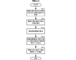
- FIG. 5 is a flowchart showing a power management flow of the management center of the positioning terminal management system according to the second embodiment of the present invention.
- the control mode determination unit 212 of the management unit 201A determines the power control mode for each positioning terminal using the relative positions of the plurality of positioning terminals 10 and the movement restriction information (S214). For example, as described above, the control mode determination unit 212 sets the power control mode of the power saving mode for the positioning terminal that does not move immediately, and continuously measures the positioning terminal that can move immediately. Set the power control mode in steady mode. At this time, the control mode determination unit 212 also considers movement restriction information and identifies a positioning terminal that moves immediately and a positioning terminal that does not move immediately.
- the vehicles 91, 92, 93 are parked in parallel along the one-way direction.
- the vehicle 91 is at the top, the vehicle 92 is in the middle, and the vehicle 93 is at the end.
- the positioning terminal 11 is attached to the vehicle 91, the positioning terminal 12 is attached to the vehicle 92, and the positioning terminal 13 is attached to the vehicle 93.
- the positioning terminals 11, 12, and 13 have the same configuration as the positioning terminal 10 described above.
- the management unit 201 determines the position of the positioning terminals 11, 12, 13 and the direction of the vehicles 91, 92, 93 equipped with the positioning terminals 11, 12, 13. Then, it is detected that there is no vehicle in front of the vehicle 91 equipped with the positioning terminal 11. Further, the management unit 201 detects from the movement restriction information that the yard 900 in which the vehicles 91, 92, and 93 equipped with the positioning terminals 11, 12, and 13 are parked is one-way. Then, the management unit 201 detects that the forward direction of the vehicle 91 equipped with the positioning terminal 11 is the same as the one-way traveling direction.
- the management unit 201 detects that the vehicle 91 to which the positioning terminal 11 is attached may move forward. Therefore, the management unit 201 sets the power control mode in the steady mode (power control mode for performing continuous measurement) to the positioning terminal 11 so as to maintain the current positioning and azimuth measurement.
- the management unit 201 determines the position of the positioning terminals 11, 12, 13 and the direction of the vehicles 91, 92, 93 equipped with the positioning terminals 11, 12, 13. Then, it is detected that the vehicle 91 equipped with the positioning terminal 11 is stopped in front of the vehicle 92 equipped with the positioning terminal 12.
- the management unit 201 determines from the detection result and the movement restriction information that the vehicle 92 to which the positioning terminal 12 is attached does not move unless the vehicle 91 to which the positioning terminal 11 is attached moves. Therefore, the positioning terminal 12 does not need to perform positioning at the same frequency as the positioning terminal 11. Using this concept, the management unit 201 sets the power control mode of the power saving mode for the positioning terminal 12.
- FIG. 7 is a flowchart showing a power management flow of the management center of the positioning terminal management system according to the third embodiment of the present invention.
- the configuration of the positioning terminal management system according to this embodiment is the same as that of the positioning terminal management system according to the first embodiment, and the processing content executed by the control mode determination unit 212 of the management unit 201 of the management center 20 is different.
- Other configurations and processes are the same as those in the first embodiment. Therefore, only the process executed by the control mode determination unit 212 will be specifically described.
- Steps S221 and S222 are the same as steps S201 and S202 in FIG.
- the control mode determination unit 212 acquires time information for a vehicle equipped with a plurality of positioning terminals 10 (S223).
- the time information is information relating to the movement of the vehicle with time such that the vehicle is stored in a state where the vehicle has stopped for a plurality of days, for example.
- the control mode determination unit 212 determines the power control mode for each positioning terminal using the relative positions of the plurality of positioning terminals 10 and time information (S224). For example, as described above, the power-saving mode power supply control mode is set for a positioning terminal that does not move immediately, and the stationary mode power supply that enables continuous positioning for a positioning terminal that can move immediately Set the control mode. At this time, if the movement does not exist for a long period of time, the control mode determination unit 212 not only stops the positioning signal receiving unit 103 and the sensor 105 but also reduces the communication frequency of the terminal side communication unit 104. Good. That is, depending on the situation, the power control mode may be set by providing the above-described steps in the power saving mode.
- a vehicle is shown as an example of an object equipped with a positioning terminal, but the configuration and processing of the present invention can be applied to any object that is movable.
- the mode in which positioning is performed using the positioning signal has been described.
- the power management and power control according to the present invention can be applied even when other positioning methods of the ultrasonic signal are used. it can.
- a plurality of positioning terminals and a management center that are power management targets are provided separately, but any one of the plurality of positioning terminals is provided with the function of a management unit. May be.
- the management unit of each positioning terminal may determine at least the power control mode for the own terminal from the relative position with other positioning terminals.
- Positioning terminal management system 10 10A, 11-19: Positioning terminal 20, 20A: Management center 91-99: Vehicle 101: Control unit 102: Power supply 103: Positioning signal receiving unit 104: Terminal side communication unit 105: Sensors 201 and 201A: Management unit 211: Relative position detection unit 212: Control mode determination unit 213: Restriction information acquisition unit 202: Center side communication unit 900: Yard ANTS: Positioning antennas ANTT, ANTt: Communication antennas
Landscapes
- Physics & Mathematics (AREA)
- General Physics & Mathematics (AREA)
- Engineering & Computer Science (AREA)
- Theoretical Computer Science (AREA)
- General Engineering & Computer Science (AREA)
- Telephone Function (AREA)
Abstract
【課題】状況に応じたより適切な電源管理が可能な測位端末の管理システムを提供する。 【解決手段】測位端末管理システム1は、複数の測位端末10と管理部201とを備える。複数の測位端末は、それぞれに制御部101および測位信号受信部103を備える。測位信号受信部103は、測位信号を受信して自端末の位置を算出する。制御部101は、電源制御モードに基づいて自端末の電源制御を行う。管理部201は、複数の測位端末10の位置を用いて測位端末毎の電源制御モードを決定する。
Description
本発明は、測位端末の消費電力の管理を行う測位端末管理システムおよび測位端末管理方法に関する。
特許文献1には、測位端末の電源管理を行う方法が記載されている。特許文献1に記載の測位端末は、GPSによる測位機能を有するGPSブロックと、端末の各種機能を実行する端末装置ブロックとを備える。
特許文献1に記載の測位端末は、コールドスタート時やウォームスタート時に、GPSブロックのみに電源を供給し、端末装置ブロックへの電源供給を制限している。これにより、測位端末の消費電力は抑制される。
しかしながら、特許文献1に記載の測位端末では、自端末外の情報を参照することができない。このため、電源の管理に利用可能な情報が少なく、より省電力化が可能な状況であっても、省電力化できない場合がある。
したがって、本発明の目的は、より状況に応じた電源管理が可能な測位端末の管理システム、および測位端末の管理方法を提供することにある。
測位端末管理システムは、複数の測位端末と管理部とを備える。複数の測位端末は、それぞれに制御部および測位信号受信部を備える。測位信号受信部は、測位信号を受信して自端末の位置を算出する。制御部は、電源制御モードに基づいて自端末の電源制御を行う。管理部は、複数の測位端末の位置を用いて測位端末毎の電源制御モードを決定する。
この構成では、管理部によって、複数の測位端末の位置を用いて測位端末毎の電源管理が実現される。これにより、各測位端末では、自端末内の情報だけでなく、外部からの情報を用いて電源管理が実行される。
この発明によれば、自装置外からの情報も用いて電源管理を行うことができ、測位端末に対するより適切な省電力化を実現することができる。
本発明の第1の実施形態に係る測位端末管理システムおよび測位端末管理方法について、図を参照して説明する。図1は、本発明の第1の実施形態に係る測位端末管理システムの構成を示すブロック図である。
測位端末管理システム1は、複数の測位端末10と管理センタ20とを備える。
測位端末10は、制御部101、電源102、測位信号受信部103、端末側通信部104、センサ105、測位用アンテナANTS、および、通信用アンテナANTTを備える。なお、測位端末10は、センサ105を備えていてもいなくてもよい。
測位端末10は、制御部101、電源102、測位信号受信部103、端末側通信部104、センサ105、測位用アンテナANTS、および、通信用アンテナANTTを備える。なお、測位端末10は、センサ105を備えていてもいなくてもよい。
制御部101は、測位端末10の全体制御を行う。制御部101は、管理センタ20から受けた電源制御モードにしたがって、測位信号受信部103、センサ105、および、端末側通信部104に対する電源制御を行う。具体的な電源制御方法は、後述する。
電源制御モードは、例えば、省電力モードと現状の電力供給を維持する定常モードとを有する。定常モードでは、制御部101は、測位端末10の全ての機能部に電力を供給する。省電力モードでは、制御部101は、測位端末10を構成する複数の機能部の一部に対する電力供給を停止する。省電力モードは、複数の段階に区分することもできる。例えば、測位信号受信部103への電力供給を停止するモード、センサ105への電力供給を停止するモード、測位信号受信部103およびセンサ105への電力供給を停止するモード、端末側通信部104の通信頻度を低下させ、間欠動作させるモード、制御部101以外への電力供給を停止するモードがある。
電源102は、制御部101、測位信号受信部103、端末側通信部104、および、センサ105に電力を供給する。この際、電源102は、制御部101からの電源制御を受けて電力を供給する。
測位信号受信部103は、測位用アンテナANTSに接続している。測位信号受信部103は、測位用アンテナANTSで受信した測位信号を捕捉追尾する。測位信号受信部103は、追尾している測位信号を用いて既知の方法で測位を行って測位端末10の位置を算出する。測位信号受信部103は、算出した位置を制御部101および端末側通信部104に出力する。
センサ105は、加速度センサ、角速度センサ、地磁気センサ等の各種センサの内、少なくとも1種類を備える。センサ105はセンサ計測値を制御部101および端末側通信部104に出力する。例えば、センサ105が加速度センサであれば、計測した加速度を制御部101および端末側通信部104に出力する。
端末側通信部104は、通信用アンテナANTTを介して、管理センタ20のセンタ側通信部202とデータの通信を行う。端末側通信部104は、測位端末10の位置とセンサ計測値を、センタ側通信部202に送信する。端末側通信部104は、センタ側通信部202から送信された電源制御モードを受信して制御部101に出力する。
管理センタ20は、管理部201、センタ側通信部202、および、通信用アンテナANTtを備える。
管理部201は、相対位置検出部211、および、制御モード決定部212を備える。相対位置検出部211は、複数の測位端末10から送信された各測位端末の位置を用いて、複数の測位端末10の相対位置を検出する。相対位置検出部211は、相対位置を制御モード決定部212に出力する。制御モード決定部212は、複数の測位端末10の相対位置を用いて、複数の測位端末10のそれぞれに固有の電源制御モードを決定する。なお、具体的な電源制御モードの決定方法は後述する。
センタ側通信部202は、通信用アンテナANTtを介して、各測位端末10の端末側通信部104とデータ通信を行う。センタ側通信部202は、各測位端末10の端末側通信部104から送信された位置およびセンサ計測値を受信し、管理部201に出力する。なお、センタ側通信部202は、少なくとも位置を管理部201に出力すればよい。この場合、センサ計測値は、管理センタ20の記憶部(図示せず)に記憶すればよい。センタ側通信部202は、管理部201で決定した電源制御モードを、各測位端末10の端末側通信部104に送信する。
このような構成からなる測位端末管理システムは、次に示す方法によって、複数の測位端末10の電源管理を行う。図2は、本発明の第1の実施形態に係る測位端末管理システムの電源管理フローを示すフローチャートである。
複数の測位端末10の測位信号受信部103は、測位信号を受信して、自装置の位置を算出する(S101)。複数の測位端末10の端末側通信部104は、自装置の位置を管理センタ20に送信する(S102)。
管理センタ20の管理部201の相対位置検出部211は、センタ側通信部202を介して、複数の測位端末10の位置を取得する(S201)。相対位置検出部211は、取得した位置に基づいて、複数の測位端末10の相対位置を算出する(S202)。管理部201の制御モード決定部212は、相対位置から測位端末10毎の電源制御モードを決定する。例えば、制御モード決定部212は、電源制御モードを決定する対象の測位端末10に対して特定方位の特定距離内に他の測位端末10があるという条件に基づいて電源制御モードを決定する。制御モード決定部212は、対象の測位端末10がこの条件を満たす場合に、省電力モードの電源制御モードを設定する。一方、制御モード決定部212は、対象の測位端末10がこの条件を満たさない場合に、定常モードの電源制御モードを設定する。制御モード決定部212は、位置を取得した全ての測位端末に10に対して、電源制御モードを設定する。
管理部201の制御モード決定部212は、センタ側通信部202を介して、複数の測位端末10に、電源制御モードを通知する(S204)。電源制御モードには、複数の測位端末10のそれぞれを識別する固有ID等の識別情報が添付されている。
複数の測位端末10の制御部101は、端末側通信部104を介して、電源制御モードを受信する(S103)。各制御部101は、識別情報から自端末に設定された電源制御モードを検出する。制御部101は、検出した電源制御モードに応じた電源制御を行う(S104)。例えば、制御部101は、省電力モードの電源制御モードを検出すると、測位信号受信部103を停止させて、測位信号受信部103への電力供給を停止する。また、制御部101は、省電力モードの電源制御モードを検出すると、センサ105を停止させて、センサ105への電力供給を停止する。さらには、制御部101は、より低電力を求める省電力モードの電源制御モードを検出すると、測位信号受信部103およびセンサ105を停止させてこれらへの電力供給を停止するとともに、端末側通信部104の通信頻度を低下させる。また、最も消費電力を小さくする省電力モードの電源制御モードを検出すると、制御部101は、制御部101以外の機能部への電力供給を停止する。
このような処理を行うことによって、測位端末10は、自端末の位置だけでなく、自端末と他端末との相対位置に基づいて電源制御を行うことができる。したがって、測位端末10は、自端末の置かれた状況により正確に則した電源制御、例えば、省電力モードへの切替を実現することができる。
なお、上述の説明では、測位端末の位置を用いて電源制御モードを決定する態様を示したが、センサ計測値(例えば、方位等)も用いて電源制御モードを決定してもよい。
このような構成および処理は、次のような状況で活用することができる。図3は、本発明の第1の実施形態に係る電源制御モードの設定の具体的な一例を説明するための車両の配置図である。
図3に示すように、車両91,92,93,94,95,96,97,98,99は、縦三列×横三列に駐車されている。測位端末11は車両91に装着され、測位端末12は車両92に装着され、測位端末13は車両93に装着されている。測位端末14は車両94に装着され、測位端末15は車両95に装着され、測位端末16は車両96に装着されている。測位端末17は車両97に装着され、測位端末18は車両98に装着され、測位端末19は車両99に装着されている。測位端末11-19は、上述の測位端末10と同じ構成からなる。
管理部201は、各測位端末11-19の位置を取得し、これらの相対位置を算出する。具体的には、管理部201は、電源制御モードの設定対象の測位端末に対する他の測位端末の方位および距離をそれぞれに算出する。
ここで、測位端末15を電源制御モードの設定対象とすると、管理部201は、測位端末11-19の位置から、測位端末15を基準とした各測位端末11-14,16-19の相対位置を算出する。具体的には、管理部201は、測位端末15の位置を基準点とした各測位端末11-14,16-19の位置および方位を算出する。
管理部201は、この算出結果から、測位端末15の位置を基準点とする直交する二方向において、測位端末12,14,16,18が存在していることを検出できる。管理部201は、測位端末15に対する測位端末12,14,16,18の距離から、これらの測位端末12,14,16,18が測位端末15に近接しているか否かを検出する。例えば、管理部201は、車両91-99の大きさを予め記憶しており、車両91-99の幅、長さ程度、もしくはそれ以下の距離で設定した閾値と、測位端末12,14,16,18と測位端末15との距離(測位端末間距離)とを比較する。管理部201は、測位端末間距離が閾値以下であれば、測位端末15は、測位端末12,14,16,18に近接していると判断する。なお、この判断は、測位端末12,14,16,18のそれぞれに対して実行される。
このように、四方に測位端末12,14,16,18が近接している測位端末15が装着される車両95は、測位端末12,14,16,18が装着される車両92,94,96,98が移動しなければ、移動することはない。したがって、測位端末15は、他の測位端末と同様の頻度で測位を行う必要はない。この概念を利用して、管理部201は、測位端末15に対して省電力モードの電源制御モードを設定する。
一方、測位端末11を電源制御モードの設定対象とすると、管理部201は、二方向に近接する測位端末が無いことを検出できる。この場合、測位端末11が装備される車両91は、すぐに移動する可能性がある。したがって、管理部201は、現状の測位を維持できるように、電力供給を維持する電源制御モードを設定する。
このように、本実施形態に構成および処理を用いれば、それぞれの測位端末に対して必要最小限の消費電力で動作するように設定することができる。これにより、各測位端末は、それぞれの状況に応じたより適切な電力消費で動作することができる。
なお、上述の説明では、測位結果(位置)のみを用いる態様を示したが、センサ計測値によって方位を得られる場合、さらに適切な電源制御を行うことが可能になる。例えば、図3の態様であれば、車両91-99は、前方もしくは後方には移動できるが、横方向には直接移動できない。したがって、測位端末12,18が装備される車両92,98もすぐに移動することはない。ここで、方位を取得できることによって、車両91-99の向きも検出することができる。これを利用し、管理部201は、測位端末12,18に対しても、省電力モードの電源制御モードを設定する。
また、本実施形態の構成および処理では、複数の測位端末10(およびこれらが装備される車両)で1つのグループを構成し、当該グループを構成する複数の測位端末10の電源管理として利用することができる。これにより、複数の測位端末10の電源をグループとして管理し、且つ、各測位端末10の状況に応じた適切な電源管理を実現することができる。
次に、第2の実施形態に係る測位端末管理システムおよび測位端末管理方法について、図を参照して説明する。図4は、本発明の第2の実施形態に係る測位端末管理システムの構成を示すブロック図である。
本実施形態に係る測位端末管理システム1Aは、第1の実施形態に係る測位端末管理システム1に対して、管理センタ20Aの構成において異なる。他の構成は、第1の実施形態に係る測位単端末管理システム10と同じである。
管理センサ20Aは、管理部201Aおよびセンタ側通信部202を備える。センタ側通信部202は、第1の実施形態に係るセンタ側通信部202と同じであり、管理部201Aは、第1の実施形態に係る管理部201に対して、制御情報取得部213を追加し、制御モード決定部212の電源制御モードの決定方法において異なる。
制限情報取得部213は、外部のネットワークNW等を介して移動制限情報を取得する。移動制限情報とは、例えば、外部の地図データベース等から取得することが可能である。移動制限情報とは、例えば、測位端末が車両に装備されている場合、車両の通行可能な方向(一方通行か否か)等である。制限情報取得部213は、移動制限情報を制御モード決定部212に出力する。
制御モード決定部212は、相対位置と移動制限情報とを用いて、測位端末10毎の電源制御モードを決定する。
具体的には、管理センタ20Aは次に示す処理を実行する。図5は、本発明の第2の実施形態に係る測位端末管理システムの管理センタの電源管理フローを示すフローチャートである。
ステップS211,S212は、図2のステップS201,S202と同じである。管理部201の制限情報取得部213は、複数の測位端末10の位置から、当該位置を対象とする移動制限情報を取得する(S213)。
管理部201Aの制御モード決定部212は、複数の測位端末10の相対位置と移動制限情報とを用いて、測位端末毎の電源制御モードを決定する(S214)。例えば、制御モード決定部212は、上述のように、すぐに移動しない測位端末に対しては省電力モードの電源制御モードを設定し、すぐに移動可能な測位端末に対しては継続的に測位が可能な定常モードの電源制御モードを設定する。この際、制御モード決定部212は、移動制限情報も考慮した上で、すぐに移動する測位端末と、すぐには移動しない測位端末を識別する。
管理部201Aは、電源制御モードを複数の測位端末10に通知する(S215)。複数の測位端末10は、自装置に設定された電源制御モードに応じて電源制御を行う。
このような構成および処理は、次のような状況で活用することができる。図6は、本発明の第2の実施形態に係る電源制御モードの設定の具体的な一例を説明するための車両の配置図である。
図5に示すように、車両91,92,93は、一方通行の方向に沿って縦列駐車されている。先頭が車両91で、真ん中が車両92で、最後尾が車両93である。測位端末11は車両91に装着され、測位端末12は車両92に装着され、測位端末13は車両93に装着されている。測位端末11,12,13は、上述の測位端末10と同じ構成からなる。
測位端末11を電源制御モードの設定対象とすると、管理部201は、測位端末11,12,13の位置、および、測位端末11,12,13が装備された車両91,92,93の方位から、測位端末11が装備された車両91の前方に車両がないことを検出する。また、管理部201は、移動制限情報から、測位端末11,12,13が装備された車両91,92,93が駐車されたヤード900が一方通行であることを検出する。そして、管理部201は、測位端末11が装備された車両91の前方方向が一方通行の進行方向と同じであること検出する。管理部201は、これらの結果から、測位端末11が装着された車両91は前方に移動する可能性があることを検出する。したがって、管理部201は、測位端末11に対して、現状の測位、方位の計測を維持するように、定常モードの電源制御モード(継続的な計測を行う電源制御モード)を設定する。
測位端末12を電源制御モードの設定対象とすると、管理部201は、測位端末11,12,13の位置、および、測位端末11,12,13が装備された車両91,92,93の方位から、測位端末12が装備された車両92の前方に測位端末11が装備された車両91が停まっていることを検出する。
管理部201は、この検出結果と移動制限情報から、測位端末11が装着される車両91が移動しなければ、測位端末12が装着される車両92は移動することはないと判定する。したがって、測位端末12は、測位端末11と同様の頻度で測位を行う必要はない。この概念を利用して、管理部201は、測位端末12に対して省電力モードの電源制御モードを設定する。
管理部201は、測位端末13に対しても、測位端末12と同様の判断を行い、測位端末13に対して省電力モードの電源制御モードを設定する。
このように、本実施形態の構成および処理を用いることによって、複数の測位端末の位置関係のみでなく、複数の測位端末が装備された車両に対する移動制限条件も用いて、より適切に電源制御を行うことができる。
次に、第3の実施形態に係る測位端末管理システムおよび測位端末管理方法について、図を参照して説明する。図7は、本発明の第3の実施形態に係る測位端末管理システムの管理センタの電源管理フローを示すフローチャートである。
本実施形態に係る測位端末管理システムの構成は、第1の実施形態に係る測位端末管理システムと同じであり、管理センタ20の管理部201の制御モード決定部212で実行する処理内容が異なる。他の構成および処理は、第1の実施形態と同じである。したがって、制御モード決定部212で実行する処理のみを具体的に説明する。
ステップS221,S222は、図2のステップS201,S202と同じである。制御モード決定部212は、複数の測位端末10が装備された車両に対する時刻情報を取得する(S223)。時刻情報とは、例えば、車両が複数日に亘って停車した状態で保管されるというような時刻を伴う車両の移動に関する情報である。
制御モード決定部212は、複数の測位端末10の相対位置と時刻情報とを用いて、測位端末毎の電源制御モードを決定する(S224)。例えば、上述のように、すぐに移動しない測位端末に対しては省電力モードの電源制御モードを設定し、すぐに移動可能な測位端末に対しては継続的に測位が可能な定常モードの電源制御モードを設定する。この際、制御モード決定部212は、移動が長い期間存在しない場合には、測位信号受信部103およびセンサ105を停止させるだけでなく、端末側通信部104の通信頻度を低下させるようにしてもよい。すなわち、状況に応じて、省電力モードに上述のような段階を設けて電源制御モードを設定してもよい。
管理部201は、電源制御モードを複数の測位端末10に通知する(S225)。複数の測位端末10は、自装置に設定された電源制御モードに応じて電源制御を行う。
このような構成および処理を用いることによって、より適切に電源制御を行うことができる。
なお、第3の実施形態に係る構成および方法と第2の実施形態に係る構成および方法とを組み合わせてもよい。
また、上述の各実施形態では、測位端末が装備される物として車両を例に示したが、移動可能な物体であれば、本願発明の構成および処理を適用することができる。
また、上述の各実施形態では、測位信号を用いて測位を行う態様を示したが、超音波信号の他の測位方法を用いる場合にも、本願発明の電源管理および電源制御を適用することができる。
また、上述の各実施形態では、電源管理の対象となる複数の測位端末と管理センタは、別に設けられているが、複数の測位端末の内、いずれか1つに管理部の機能を持たせてもよい。この場合、各測位端末の管理部は、他の測位端末との相対位置から少なくとも自端末に対する電源制御モードを決定すればよい。この構成を用いることによって、複数の測位端末とは別に管理センタを設けなくてもよく、各測位端末は自立式の電源制御を行うことができる。
1,1A:測位端末管理システム
10,10A,11-19:測位端末
20,20A:管理センタ
91-99:車両
101:制御部
102:電源
103:測位信号受信部
104:端末側通信部
105:センサ
201,201A:管理部
211:相対位置検出部
212:制御モード決定部
213:制限情報取得部
202:センタ側通信部
900:ヤード
ANTS:測位用アンテナ
ANTT,ANTt:通信用アンテナ
10,10A,11-19:測位端末
20,20A:管理センタ
91-99:車両
101:制御部
102:電源
103:測位信号受信部
104:端末側通信部
105:センサ
201,201A:管理部
211:相対位置検出部
212:制御モード決定部
213:制限情報取得部
202:センタ側通信部
900:ヤード
ANTS:測位用アンテナ
ANTT,ANTt:通信用アンテナ
Claims (12)
- 測位信号を受信して自端末の位置を算出する測位信号受信部、および、電源制御モードに基づいて自端末の電源制御を行う制御部をそれぞれに備えた複数の測位端末と、
前記複数の測位端末の位置を用いて測位端末毎の前記電源制御モードを決定する管理部と、
を備えた、測位端末管理システム。 - 請求項1に記載の測位端末管理システムであって、
前記管理部を備えた管理センタを前記複数の測位端末とは別に備え、
前記管理センタは、前記複数の測位端末に対して前記電源制御モードを通知し、
前記複数の測位端末の制御部は、通知された自端末の電源制御モードに基づいて電源制御を行う、
測位端末管理システム。 - 請求項2に記載の測位端末管理システムであって、
前記管理センタは、前記複数の測位端末の位置を受信し、前記電源制御モードを通知するセンタ側通信部を備え、
前記測位端末は、自端末の位置を送信し、通知された前記電源制御モードを受信する端末側通信部を備える、
測位端末管理システム。 - 請求項1に記載の測位端末管理システムであって、
前記管理部は、前記測位端末に備えられており、
前記管理部は、少なくとも該管理部が備え付けられた測位端末に対する電源制御モードを決定する、
測位端末管理システム。 - 請求項1乃至請求項4のいずれかに記載の測位端末管理システムであって、
前記管理部は、
前記複数の測位端末が算出した位置から前記複数の測位端末の相対位置を検出する相対位置検出部と、
前記複数の測位端末の相対位置から前記電源制御モードを決定する制御モード決定部と、
を備える、測位端末管理システム。 - 請求項5に記載の測位端末管理システムであって、
前記管理部は、
前記複数の測位端末の移動制限情報を取得する制限情報取得部を備え、
前記制御モード決定部は、前記移動制限情報も用いて前記電源制御モードを決定する、
測位端末管理システム。 - 請求項1乃至請求項6のいずれかに記載の測位端末管理装置であって、
前記管理部は、
前記複数の測位端末の移動の停止期間と時刻とを時刻情報として取得し、
前記時刻情報も用いて前記電源制御モードを決定する、
測位端末管理システム。 - 測位信号を受信して自端末の位置を算出する測位信号受信部と、
前記自端末を含む複数の測位端末が算出した位置を用いて自端末の電源制御モードを決定する管理部と、
前記電源制御モードを用いて自端末の電源制御を行う制御部と、
を備えた測位端末。 - 複数の測位端末が算出した位置から前記複数の測位端末の相対位置を検出する相対位置検出部と、
前記複数の測位端末の相対位置から、測位端末毎の電源制御モードを決定する制御モード決定部と、
を備える、管理センタ。 - 複数の測位端末がそれぞれに測位信号を受信して前記複数の測位端末の位置を算出する測位信号受信工程と、
前記複数の測位端末が算出した位置を用いて測位端末毎の電源制御モードを決定する制御モード決定工程と、
前記複数の測位端末が、それぞれに自端末の前記電源制御モードに基づいて電源制御を行う電源制御工程と、
を有する、測位端末管理方法。 - 請求項10に記載の測位端末管理方法であって、
前記複数の測位端末の移動制限情報を取得する制限情報取得工程を、有し、
前記制御モード決定工程は、前記移動制限情報も用いて前記電源制御モードを決定する、
測位端末管理方法。 - 請求項10または請求項11に記載の測位端末管理方法であって、
前記複数の測位端末の移動の停止期間と時刻とを時刻情報として取得する時刻情報取得工程を有し、
前記制御モード決定工程は、前記時刻情報も用いて前記電源制御モードを決定する、
測位端末管理方法。
Applications Claiming Priority (2)
| Application Number | Priority Date | Filing Date | Title |
|---|---|---|---|
| JP2015-157038 | 2015-08-07 | ||
| JP2015157038 | 2015-08-07 |
Publications (1)
| Publication Number | Publication Date |
|---|---|
| WO2017026205A1 true WO2017026205A1 (ja) | 2017-02-16 |
Family
ID=57983189
Family Applications (1)
| Application Number | Title | Priority Date | Filing Date |
|---|---|---|---|
| PCT/JP2016/069908 Ceased WO2017026205A1 (ja) | 2015-08-07 | 2016-07-05 | 測位端末管理システム、測位端末、管理センタ、測位端末管理方法 |
Country Status (1)
| Country | Link |
|---|---|
| WO (1) | WO2017026205A1 (ja) |
Citations (3)
| Publication number | Priority date | Publication date | Assignee | Title |
|---|---|---|---|---|
| JP2003272062A (ja) * | 2002-03-18 | 2003-09-26 | Hitachi Ltd | 警告発生方法および装置 |
| JP2006146654A (ja) * | 2004-11-22 | 2006-06-08 | Matsushita Electric Works Ltd | 異常通報装置およびそれを備えて成る位置情報通信システムならびに異常通知方法 |
| JP2013172277A (ja) * | 2012-02-20 | 2013-09-02 | Fujitsu Ltd | 情報処理システムの制御方法、サーバ装置、サーバ装置の制御プログラム、クライアント装置及びクライアント装置の制御プログラム |
-
2016
- 2016-07-05 WO PCT/JP2016/069908 patent/WO2017026205A1/ja not_active Ceased
Patent Citations (3)
| Publication number | Priority date | Publication date | Assignee | Title |
|---|---|---|---|---|
| JP2003272062A (ja) * | 2002-03-18 | 2003-09-26 | Hitachi Ltd | 警告発生方法および装置 |
| JP2006146654A (ja) * | 2004-11-22 | 2006-06-08 | Matsushita Electric Works Ltd | 異常通報装置およびそれを備えて成る位置情報通信システムならびに異常通知方法 |
| JP2013172277A (ja) * | 2012-02-20 | 2013-09-02 | Fujitsu Ltd | 情報処理システムの制御方法、サーバ装置、サーバ装置の制御プログラム、クライアント装置及びクライアント装置の制御プログラム |
Similar Documents
| Publication | Publication Date | Title |
|---|---|---|
| US11783699B2 (en) | Intersection information distribution apparatus and intersection information distribution method | |
| US8041469B2 (en) | Determining relative spatial information between vehicles | |
| US20140297063A1 (en) | Vehicle specifying apparatus | |
| US8676486B2 (en) | Vehicular information processing device | |
| US9418549B2 (en) | Apparatus and method for recognizing position of vehicle | |
| JP4569652B2 (ja) | 認識システム | |
| RU2730442C1 (ru) | Надежный и достоверный способ, устройство и система для измерения скорости в реальном времени и непрерывного определения положения | |
| US9889798B1 (en) | Detection of a target object utilizing automotive radar | |
| JP4862693B2 (ja) | 通信システム、端末機及び車載機 | |
| US9410808B2 (en) | Apparatus and method for detecting location information using navigation algorithm | |
| US10310076B2 (en) | Driving lane detection device and driving lane detection method | |
| US8892331B2 (en) | Drive assist system and wireless communication device for vehicle | |
| US9171463B2 (en) | Congestion estimation device | |
| JP2020193954A (ja) | 位置補正サーバ、位置管理装置、移動体の位置管理システム及び方法、位置情報の補正方法、コンピュータプログラム、車載装置並びに車両 | |
| US10816972B2 (en) | Collective determination among autonomous vehicles | |
| JP2008046873A (ja) | 車両同定装置、位置算出装置 | |
| CN104748756A (zh) | 使用云计算测量车辆位置的方法 | |
| US20200189563A1 (en) | Vehicle control device and vehicle control method | |
| CN110941003B (zh) | 车辆识别方法,装置,存储介质及电子设备 | |
| US10783785B2 (en) | Train presence detection apparatus | |
| WO2017026205A1 (ja) | 測位端末管理システム、測位端末、管理センタ、測位端末管理方法 | |
| JP2009064329A (ja) | 先頭車両判定装置 | |
| JPWO2019239471A1 (ja) | 運転支援装置、運転支援システムおよび運転支援方法 | |
| US20220398850A1 (en) | Information generation device, information generation method, and non-transitory computer-readable storage medium | |
| US20160347365A1 (en) | Method and device for supporting a driving maneuver of a motor vehicle |
Legal Events
| Date | Code | Title | Description |
|---|---|---|---|
| 121 | Ep: the epo has been informed by wipo that ep was designated in this application |
Ref document number: 16834902 Country of ref document: EP Kind code of ref document: A1 |
|
| NENP | Non-entry into the national phase |
Ref country code: DE |
|
| NENP | Non-entry into the national phase |
Ref country code: JP |
|
| 122 | Ep: pct application non-entry in european phase |
Ref document number: 16834902 Country of ref document: EP Kind code of ref document: A1 |