WO2017022343A1 - Clutch drive unit and saddled vehicle - Google Patents
Clutch drive unit and saddled vehicle Download PDFInfo
- Publication number
- WO2017022343A1 WO2017022343A1 PCT/JP2016/068070 JP2016068070W WO2017022343A1 WO 2017022343 A1 WO2017022343 A1 WO 2017022343A1 JP 2016068070 W JP2016068070 W JP 2016068070W WO 2017022343 A1 WO2017022343 A1 WO 2017022343A1
- Authority
- WO
- WIPO (PCT)
- Prior art keywords
- clutch
- crank arm
- pressing
- moment
- drive unit
- Prior art date
Links
Images


Classifications
-
- F—MECHANICAL ENGINEERING; LIGHTING; HEATING; WEAPONS; BLASTING
- F16—ENGINEERING ELEMENTS AND UNITS; GENERAL MEASURES FOR PRODUCING AND MAINTAINING EFFECTIVE FUNCTIONING OF MACHINES OR INSTALLATIONS; THERMAL INSULATION IN GENERAL
- F16D—COUPLINGS FOR TRANSMITTING ROTATION; CLUTCHES; BRAKES
- F16D29/00—Clutches and systems of clutches involving both fluid and magnetic actuation
- F16D29/005—Clutches and systems of clutches involving both fluid and magnetic actuation with a fluid pressure piston driven by an electric motor
-
- B—PERFORMING OPERATIONS; TRANSPORTING
- B60—VEHICLES IN GENERAL
- B60K—ARRANGEMENT OR MOUNTING OF PROPULSION UNITS OR OF TRANSMISSIONS IN VEHICLES; ARRANGEMENT OR MOUNTING OF PLURAL DIVERSE PRIME-MOVERS IN VEHICLES; AUXILIARY DRIVES FOR VEHICLES; INSTRUMENTATION OR DASHBOARDS FOR VEHICLES; ARRANGEMENTS IN CONNECTION WITH COOLING, AIR INTAKE, GAS EXHAUST OR FUEL SUPPLY OF PROPULSION UNITS IN VEHICLES
- B60K17/00—Arrangement or mounting of transmissions in vehicles
- B60K17/02—Arrangement or mounting of transmissions in vehicles characterised by arrangement, location, or kind of clutch
-
- B—PERFORMING OPERATIONS; TRANSPORTING
- B60—VEHICLES IN GENERAL
- B60K—ARRANGEMENT OR MOUNTING OF PROPULSION UNITS OR OF TRANSMISSIONS IN VEHICLES; ARRANGEMENT OR MOUNTING OF PLURAL DIVERSE PRIME-MOVERS IN VEHICLES; AUXILIARY DRIVES FOR VEHICLES; INSTRUMENTATION OR DASHBOARDS FOR VEHICLES; ARRANGEMENTS IN CONNECTION WITH COOLING, AIR INTAKE, GAS EXHAUST OR FUEL SUPPLY OF PROPULSION UNITS IN VEHICLES
- B60K23/00—Arrangement or mounting of control devices for vehicle transmissions, or parts thereof, not otherwise provided for
- B60K23/02—Arrangement or mounting of control devices for vehicle transmissions, or parts thereof, not otherwise provided for for main transmission clutches
-
- F—MECHANICAL ENGINEERING; LIGHTING; HEATING; WEAPONS; BLASTING
- F16—ENGINEERING ELEMENTS AND UNITS; GENERAL MEASURES FOR PRODUCING AND MAINTAINING EFFECTIVE FUNCTIONING OF MACHINES OR INSTALLATIONS; THERMAL INSULATION IN GENERAL
- F16D—COUPLINGS FOR TRANSMITTING ROTATION; CLUTCHES; BRAKES
- F16D25/00—Fluid-actuated clutches
- F16D25/08—Fluid-actuated clutches with fluid-actuated member not rotating with a clutching member
- F16D25/082—Fluid-actuated clutches with fluid-actuated member not rotating with a clutching member the line of action of the fluid-actuated members co-inciding with the axis of rotation
- F16D25/083—Actuators therefor
-
- F—MECHANICAL ENGINEERING; LIGHTING; HEATING; WEAPONS; BLASTING
- F16—ENGINEERING ELEMENTS AND UNITS; GENERAL MEASURES FOR PRODUCING AND MAINTAINING EFFECTIVE FUNCTIONING OF MACHINES OR INSTALLATIONS; THERMAL INSULATION IN GENERAL
- F16D—COUPLINGS FOR TRANSMITTING ROTATION; CLUTCHES; BRAKES
- F16D25/00—Fluid-actuated clutches
- F16D25/08—Fluid-actuated clutches with fluid-actuated member not rotating with a clutching member
- F16D25/082—Fluid-actuated clutches with fluid-actuated member not rotating with a clutching member the line of action of the fluid-actuated members co-inciding with the axis of rotation
- F16D25/086—Fluid-actuated clutches with fluid-actuated member not rotating with a clutching member the line of action of the fluid-actuated members co-inciding with the axis of rotation the clutch being actuated by a push rod extending coaxially through the input or output shaft
-
- F—MECHANICAL ENGINEERING; LIGHTING; HEATING; WEAPONS; BLASTING
- F16—ENGINEERING ELEMENTS AND UNITS; GENERAL MEASURES FOR PRODUCING AND MAINTAINING EFFECTIVE FUNCTIONING OF MACHINES OR INSTALLATIONS; THERMAL INSULATION IN GENERAL
- F16D—COUPLINGS FOR TRANSMITTING ROTATION; CLUTCHES; BRAKES
- F16D28/00—Electrically-actuated clutches
-
- B—PERFORMING OPERATIONS; TRANSPORTING
- B60—VEHICLES IN GENERAL
- B60Y—INDEXING SCHEME RELATING TO ASPECTS CROSS-CUTTING VEHICLE TECHNOLOGY
- B60Y2200/00—Type of vehicle
- B60Y2200/10—Road Vehicles
- B60Y2200/12—Motorcycles, Trikes; Quads; Scooters
-
- F—MECHANICAL ENGINEERING; LIGHTING; HEATING; WEAPONS; BLASTING
- F16—ENGINEERING ELEMENTS AND UNITS; GENERAL MEASURES FOR PRODUCING AND MAINTAINING EFFECTIVE FUNCTIONING OF MACHINES OR INSTALLATIONS; THERMAL INSULATION IN GENERAL
- F16D—COUPLINGS FOR TRANSMITTING ROTATION; CLUTCHES; BRAKES
- F16D25/00—Fluid-actuated clutches
- F16D25/08—Fluid-actuated clutches with fluid-actuated member not rotating with a clutching member
- F16D2025/081—Hydraulic devices that initiate movement of pistons in slave cylinders for actuating clutches, i.e. master cylinders
-
- F—MECHANICAL ENGINEERING; LIGHTING; HEATING; WEAPONS; BLASTING
- F16—ENGINEERING ELEMENTS AND UNITS; GENERAL MEASURES FOR PRODUCING AND MAINTAINING EFFECTIVE FUNCTIONING OF MACHINES OR INSTALLATIONS; THERMAL INSULATION IN GENERAL
- F16D—COUPLINGS FOR TRANSMITTING ROTATION; CLUTCHES; BRAKES
- F16D48/00—External control of clutches
- F16D48/02—Control by fluid pressure
- F16D2048/0212—Details of pistons for master or slave cylinders especially adapted for fluid control
-
- F—MECHANICAL ENGINEERING; LIGHTING; HEATING; WEAPONS; BLASTING
- F16—ENGINEERING ELEMENTS AND UNITS; GENERAL MEASURES FOR PRODUCING AND MAINTAINING EFFECTIVE FUNCTIONING OF MACHINES OR INSTALLATIONS; THERMAL INSULATION IN GENERAL
- F16D—COUPLINGS FOR TRANSMITTING ROTATION; CLUTCHES; BRAKES
- F16D2125/00—Components of actuators
- F16D2125/18—Mechanical mechanisms
- F16D2125/20—Mechanical mechanisms converting rotation to linear movement or vice versa
- F16D2125/22—Mechanical mechanisms converting rotation to linear movement or vice versa acting transversely to the axis of rotation
- F16D2125/26—Cranks
Definitions
- the present invention relates to a clutch drive unit mounted on a saddle-ride type vehicle such as a motorcycle or a four-wheel buggy, and a saddle-ride type vehicle equipped with the clutch drive unit.
- a power transmission device is provided to transmit driving force generated by an engine (prime mover) to driving wheels.
- the power transmission device is a mechanical device that transmits and transmits the rotational speed of the crankshaft to the drive wheel while shifting and connecting to and disconnecting from the crankshaft of the engine, and mainly includes a clutch and a transmission.
- the clutch is a mechanical device that transmits the rotational driving force of the crankshaft to the transmission side while being connected to and disconnected from the crankshaft of the engine.
- the transmission is a mechanical device that changes the number of rotations of the crankshaft of the engine at a plurality of shift speeds constituted by a combination of a plurality of gears and transmits it to the drive wheel side.
- the clutch is configured to selectively switch between transmission and disconnection of the rotational driving force from the engine by driving the push rod forward and backward by a clutch driving unit including an electric motor.
- a clutch driving unit including an electric motor.
- Patent Literature 1 discloses a clutch actuator as a clutch drive unit including an assist spring that assists the rotational driving force of a clutch motor.
- the present invention has been made to address the above-described problems, and an object of the present invention is to provide a clutch drive unit and a clutch drive unit that can reduce the power consumption of an electric motor and reduce the size and weight of the apparatus.
- the object is to provide a saddle-ride type vehicle provided.
- the present invention is characterized in that the rotational speed is controlled by an engine that generates a driving force by combustion of fuel and a plurality of gear trains that constitute a plurality of shift stages having different gear ratios.
- Switching between transmission and disconnection of clutch driving force in a saddle-ride type vehicle having a transmission that changes speed and a clutch that selectively switches transmission and disconnection of driving force from the engine to the transmission by pressing force of a push rod A clutch drive unit for rotating a drive shaft, a crank arm connected to the drive shaft and rotated by the clutch actuator, and an output rod sliding in the cylinder by the rotation of the crank arm Hydraulic to push the push rod by Reaction force based on the reaction force from the master cylinder to be generated and the direction in which the pressing direction of the elastic body that exerts the pressing force is directed toward the rotation center of the crank arm and the clutch acting on the crank arm via the push rod and the output rod, respectively
- An extension body that is connected to a part of the crank arm in a state of being able to rotate
- the clutch drive unit is configured such that the extension body having the elastic body that exerts the pressing force is directed toward the rotation center of the crank arm and the reaction force from the clutch acting on the crank arm. Is supported so as to be rotatable within a range that resists the reaction force moment based on the above, and applies a pressing force to the crank arm.
- the elongated body applies a pressing force to the crank arm so that the pressing moment applied to the crank arm is larger than the reaction force moment.
- the clutch drive unit applies a pressing moment larger than the reaction force moment in the direction in which the extension body resists the reaction force moment against the crank arm, and therefore, even after the operation of the clutch actuator is stopped, The clutch OFF state (or clutch ON state) can be maintained.
- the clutch drive unit can reduce the power consumption of the clutch actuator and can reduce the size and weight of the device configuration.
- the clutch is a clutch spring that presses against or separates the friction plate that is rotationally driven by the driving force transmitted from the engine and the clutch plate that is disposed opposite to the friction plate and transmits the driving force to the transmission.
- the friction plate or the clutch plate is displaced while resisting the elastic force, and a push rod for separating or pressing the two together can be configured to transmit or cut off the driving force transmitted from the engine to the transmission. .
- Another feature of the present invention is that, in the clutch drive unit, the extension body rotates to the direction in which the reaction force moment acts with respect to the direction in which the pressing direction is directed toward the rotation center of the crank arm. is there.
- the clutch drive unit rotates also in the direction in which the reaction force moment acts with respect to the direction in which the elongated body moves toward the rotation center of the crank arm.
- the clutch transmission state (also referred to as “clutch ON”) can be reliably maintained even after the operation of the clutch actuator is stopped after the transition to the transmission state of the driving force in the clutch (also referred to as “clutch ON”).
- the clutch drive unit is further provided with an angle sensor for detecting the amount of rotation of the crank arm on the center axis of rotation of the crank arm.
- the clutch drive unit is provided with an angle sensor for detecting the amount of rotation of the crank arm on the rotation center axis of the crank arm. Since the degree of driving force transmission state (in other words, the degree of interruption state) can be specified by the amount of rotation of the crank arm, the degree of transmission state is grasped in a high resolution and in a short time and reflected in the clutch control. be able to.
- the present invention can be implemented not only as an invention of a clutch drive unit but also as an invention of a saddle-ride type vehicle provided with a clutch drive unit.
- the rotational speed of the engine is changed by an engine that generates a driving force by combustion of fuel and a plurality of gear trains that constitute a plurality of gear stages having different gear ratios.
- a saddle-ride type vehicle having a transmission and a clutch that selectively switches transmission and disconnection of driving force from the engine to the transmission by a pressing force of a push rod, a clutch actuator that rotates the driving shaft and a coupling to the driving shaft
- a crank arm that is rotated by a clutch actuator, a master cylinder that generates hydraulic pressure to push the push rod by sliding the output rod in the cylinder by the rotation of the crank arm, and an elastic body that exerts a pressing force
- the direction of pressing is toward the center of rotation of the crank arm It is connected to a part of the crank arm so that it can freely rotate in the direction and the direction against the reaction force moment based on the reaction force from the clutch acting on the crank arm via the push rod and the output rod, respectively.
- a clutch drive unit having an extension that applies a pressing moment in a direction opposite to the reaction force moment to the crank arm, and the extension gives the crank arm a pressing force that causes the pressing moment to be greater than the reaction force moment. Like that. Also by this, the same effect as the clutch drive unit can be expected.
- FIG. 1 is a side view schematically showing an overall configuration of a saddle-ride type vehicle including a clutch drive unit according to the present invention.
- FIG. 2 is a partial cross-sectional view schematically showing a configuration of a main part of a power transmission device in the saddle riding type vehicle shown in FIG. 1.
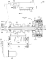
- FIG. 3 is a partially cutaway cross-sectional view schematically showing an internal structure of the clutch drive unit as viewed from line 3-3 shown in FIG.
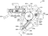
- FIG. 4 is a cross-sectional view schematically showing the internal structure of the clutch drive unit as seen from line 4-4 shown in FIG.
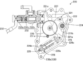
- FIG. 4 is a partially broken cross-sectional view showing an operating state when the clutch drive unit shown in FIG.
- FIG. 1 is a side view schematically showing an outline of the entire configuration of a saddle-ride type vehicle 100 including a clutch drive unit 220 according to the present invention.
- 2 is a partial cross-sectional view schematically showing a configuration of a main part of the power transmission device 200 in the saddle-ride type vehicle 100 shown in FIG.
- FIG. 3 is a cross-sectional view schematically showing the internal structure of the clutch drive unit 220 as viewed from the line 3-3 shown in FIG. 4 is a cross-sectional view schematically showing the internal structure of the clutch drive unit 220 as viewed from line 4-4 shown in FIG.
- the saddle riding type vehicle 100 is a so-called saddle riding type two-wheeled motor vehicle (so-called motorcycle) on which a user rides while straddling it.
- a front wheel 103 is supported via a front fork 102 at a front end portion of a frame 101 formed extending in the front-rear direction of the saddle-ride type vehicle 100, and a swing arm is provided at a rear end portion of the frame 101.
- a rear wheel 105 is supported via 104.
- the front fork 102 is formed to be rotatable in the left-right direction of the saddle riding type vehicle 100 with respect to the frame 101, and a handle 106 for steering the traveling direction of the saddle riding type vehicle 100 is provided at the upper end portion. Is provided.
- the saddle-ride type vehicle 100 is provided behind the handle 106 in a state where a fuel tank 107 and a seat 108 are supported by the frame 101, respectively.
- the saddle riding type vehicle 100 is provided below the fuel tank 107 in a state where the engine 110 and the power transmission device 200 are supported by the frame 101, respectively.
- Engine 110 is a prime mover that generates a rotational driving force by burning fuel. Specifically, the engine 110 introduces an air-fuel mixture consisting of fuel and air into a cylindrical cylinder (not shown) and ignites the air-fuel mixture with an ignition plug (not shown). This is a so-called reciprocating engine that generates a rotational driving force on a crankshaft (not shown) connected to the piston by causing a piston (not shown) to reciprocate in the cylinder. The rotational driving force of the crankshaft is transmitted to the clutch 210 in the power transmission device 200 via a primary drive gear attached to the end of the crankshaft.
- the engine 110 is assumed to be a so-called four-stroke engine, but may be a so-called two-stroke engine.
- the engine 110 is assumed to be a single-cylinder engine provided with one cylinder.
- the engine 110 may be an engine having two or more cylinders.
- the crankshaft is accommodated in the crankcase 111.
- the crankcase 111 is an outer casing that constitutes a part of the engine 110 that holds and accommodates some components such as the transmission 240 and the shift drum 242 that constitute the power transmission device 200 in addition to the crankshaft.
- the crankcase 111 is formed by die casting of an aluminum alloy, and is configured separately from the cylinder block 112 that houses the piston of the engine 110. However, the crankcase 111 is configured integrally with the cylinder block 112. Of course it is good.
- the power transmission device 200 is a mechanical device that transmits the rotational driving force generated by the engine 110 at a plurality of shift speeds, and mainly includes a clutch 210 and a transmission 240.
- the clutch 210 is disposed between the engine 110 and the transmission 240 on the transmission path of the rotational driving force generated by the engine 110, and transmits and blocks the rotational driving force generated by the engine 110 to the transmission 240. It is a mechanical device. Specifically, as shown in FIG. 3, the clutch 210 is provided on one end side (the right side in the figure) of the main shaft 201 extending in a shaft shape from the transmission 240.
- the main shaft 201 is a component for rotating integrally with the clutch hub 214 and transmitting a rotational driving force to the transmission 240, and is configured by a hollow shaft. In FIG. 2, hatching is omitted.
- the clutch 210 includes a plurality of friction plates 212 and a clutch plate 213 that are pressed against or separated from each other in a clutch housing 211 in which an aluminum alloy material is formed into a bottomed cylindrical shape.
- the friction plate 212 is composed of a steel plate ring body whose outer peripheral portion is radially formed in a concavo-convex shape, and a plurality of small pieces of friction material are pasted on both sides of the plate surface of these ring bodies. It is configured.
- the clutch plate 213 is formed of a steel plate ring body having an inner peripheral portion formed radially in an uneven shape.
- the friction plate 212 and the clutch plate 213 are held by a clutch housing 211 in which the friction plate 212 is rotationally driven together with the rotational drive of the engine 110, and the clutch plate 213 is connected to the clutch hub 214 connected to the main shaft 201. Is retained.
- the clutch housing 211 is formed by forming an aluminum material into a cylindrical shape with a bottom.
- the clutch housing 211 constitutes a part of the casing of the clutch 210 and a plurality of friction plates 212 on the inner circumferential surface of the clutch housing 211 in the axial direction. Can be displaced along the clutch housing 211 and can be rotated together with the clutch housing 211 by spline fitting.
- the clutch hub 214 is formed by forming an aluminum material in a substantially flange shape, and is disposed concentrically with the clutch housing 211.
- a large number of spline grooves are formed along the axial direction of the clutch hub 214 on the inner peripheral surface of the clutch hub 214, and the main shaft 201 is engaged with the spline grooves by the spline.
- a push rod 215 is provided in the hollow portion of the main shaft 201 in a state extending in the axial direction of the main shaft 201.
- One end (the left side in the figure) of the main shaft 201 is connected to the clutch drive unit 220 via a slave cylinder 234, which will be described later, and the push rod 215 is connected to the clutch drive unit 220 by hydraulic pressure generated by driving the clutch drive unit 220.
- the pressure plate 216 is pressed through the push member 215a while sliding in the hollow portion along the axial direction of the main shaft 201.
- a plurality of clutch plates 213 can be displaced along the axial direction of the clutch hub 214 and can rotate together with the clutch hub 214 on the outer peripheral surface of the clutch hub 214 with the friction plate 212 sandwiched therebetween. Each state is held by spline fitting.
- a pressure plate 216 is attached to the clutch hub 214 via a clutch spring 217.
- the pressure plate 216 is a component for bringing the friction plate 212 and the clutch plate 213 into close contact with each other by pressing the friction plate 212.
- the pressure plate 216 has an outer diameter substantially the same as the outer diameter of the clutch plate 213. It is formed in a disk shape.
- the clutch spring 217 is an elastic body that exerts an elastic pressing force that presses the pressure plate 216 toward the clutch hub 214, and is configured by a coil spring (compression spring) in which spring steel is spirally wound.
- the clutch 210 is filled with a predetermined amount of clutch oil (not shown).
- the clutch oil is mainly supplied between the friction plate 212 and the clutch plate 213 to prevent absorption of frictional heat generated between them and wear of the friction material. That is, the clutch 210 is a so-called wet multi-plate friction clutch device.
- the clutch 210 is in a disconnected state in which the friction plate 212 and the clutch plate 213 are separated from each other by the push rod 215 being pressed to the right side in the figure by the clutch drive unit 220 and the driving force of the engine 110 is not transmitted to the transmission 240.
- the clutch 210 is brought into a connected state in which the friction plate 212 and the clutch plate 213 are pressed against each other when the push rod 215 is pulled to the left in the figure by the clutch actuator 231 and the driving force of the engine 110 is transmitted to the transmission 240.
- the clutch drive unit 220 is a mechanical device for pressing the push rod 215 toward the pressure plate 216 and switching the transmission state of the driving force by the clutch 210 to the cutoff state.
- the clutch drive unit 220 includes a crank arm 221.
- the crank arm 221 is a part for pressing a piston of a master cylinder 232 described later, and is configured by forming a steel material or a sintered material into a plate shape. More specifically, the crank arm 221 is configured by including a cylindrical portion 221b, a tooth portion 221c, an output pin 222, and a receiving pin 223 on an arm main body 221a formed in a plate shape.
- the arm main body 221a is formed in a deformed shape extending in a plate shape from a part of the outer peripheral portion of the cylindrical portion 221b.
- the cylindrical portion 221b is a portion for supporting the crank arm 221 on the unit case 230 in a freely rotatable state via the connecting shaft 224, and forms a hole penetrating the arm main body 221a.
- a spline is formed on the inner peripheral surface of the cylindrical portion 221b, and the connecting shaft 224 is fitted with the spline.
- the tooth portion 221c is a portion for receiving the rotational driving force of the clutch actuator 231 via the transmission gear 226, and a plurality of convex teeth are intermittently provided along a circular arc with respect to a part of the end portion of the arm body 221a. Overhangs and is formed.
- the tooth portion 221c is formed with a length corresponding to the range in which the crank arm 221 rotates.
- An output pin 222 is provided on one side in the two rotational directions of the crank arm 221 with respect to the tooth portion 221c, and a receiving pin 223 is provided on the other side.
- the output pin 222 is a cylindrical part for pressing the end of the output rod 227, and is an outer periphery of a round bar-like pin body fixedly supported while being sandwiched between the arm body 221a and the pin holding arm 225.
- a cylindrical collar is rotatably attached to the part.
- the receiving pin 223 is a round bar-shaped part for receiving a pressing force from the elongated body 228, and both ends thereof are fitted and fixedly held in the arm main body 221a and the pin holding arm 225, respectively.
- the receiving pin 223 is located at a position through a distance farther than the output pin 222 with respect to the center of the cylinder portion 221b, which is the rotation center of the crank arm 221, in other words, with respect to the rotation center of the crank arm 221. And provided outside the output pin 222.
- the connecting shaft 224 is a round bar-like component that holds the crank arm 221 and the pin holding arm 225 so as to be integrally rotatable with respect to the unit case 230, and both ends thereof are rotatably supported by the unit case 230 via bearings.
- Splines are formed on the outer peripheral portion of the connecting shaft 224, and the crank arm 221 and the pin holding arm 225 are respectively fitted with the spline.
- the pin holding arm 225 is a component for holding the receiving pin 223 in cooperation with the crank arm 221, and is a plate that extends in parallel with the crank arm 221 from the connecting shaft 224 that is spline-fitted and sandwiches the receiving pin 223. It is formed in a shape.
- the transmission gear 226 is a mechanical element that decelerates the rotational driving force of the clutch actuator 231 and transmits it to the tooth portion 221c.
- the transmission gear 226 is a small gear that meshes with the gear portion 221c coaxially with the large gear that meshes with the drive shaft of the clutch actuator 231. It is comprised with the gearwheel, and is supported by the unit case 230 rotatably. In FIG. 4, the transmission gear 226 and a part of the unit case 230 that supports the transmission gear 226 are indicated by a two-dot chain line.
- the output rod 227 is a part that presses the piston 232b of the master cylinder 232, and is formed by forming a steel material into a round bar shape.
- the output rod 227 is held by the unit case 230 so as to be slidable along the sliding direction of the piston 232b of the master cylinder 232. That is, the output rod 227 is disposed between the piston 232b of the master cylinder 232 and the output pin 222, and transmits a pressing force between them.
- the extension body 228 is a component for maintaining the clutch OFF state, which is a state in which the driving force is interrupted in the clutch 210, by the output pin 222 pressing the piston 232b of the master cylinder 232, and mainly includes a lock spring 228a and a spring holder 228b. And a pressing body 228c.
- the lock spring 228a is an elastic body that exerts an elastic pressing force that presses the pressing body 228c against the pin 223, and is configured by a coil spring (compression spring) in which spring steel is spirally wound.
- the lock spring 228a acts on the crank arm 221 with a pressing moment PM larger than the reaction force moment RM based on the reaction force R from the clutch 210 acting on the crank arm 221 via the push rod 215 and the output rod 227, respectively.
- the strength is set to generate a pressing force P that can be generated.
- the spring holder 228b is a component that holds the lock spring 228a in a stretchable state and holds the pressing body 228c so as to be slidable along the extension / contraction direction of the lock spring 228a. More specifically, the spring holder 228b is configured such that a portion that supports one end of the lock spring 228a projects in a flange shape on the outer peripheral portion of the bottomed cylindrical body that slidably holds the pressing body 228c. ing.
- the pressing body 228c is a component for receiving the pressing force of the lock spring 228a and transmitting it to the pin 223. More specifically, the pressing body 228c has a flange-shaped portion that supports the other end of the lock spring 228a on the outer periphery of the shaft that slides in the spring holder 228b in a state of being pressed against the receiving pin 223. An overhang is formed.
- the elongated body 228 is pivotally connected to the crank arm 221 with the unit case 230 as a pivot center.
- the extension body 228 is pressed against the outer peripheral surface of the holder receiving pin 229 provided in the unit case 230 in a state where the extension portion 228 can be rotated by the pressing force of the lock spring 228a and
- the front end portion of the body 228c is provided in a state of being pressed against the outer peripheral surface of the receiving pin 223 in a slidable state in the circumferential direction by the pressing force of the lock spring 228a. That is, the elongated body 228 is provided in a state of being stretched between the receiving pin 223 and the holder receiving pin 229 by the extending force of the lock spring 228a.
- the extension body 228 is directed in a direction in which the pressing direction of the lock spring 228a is directed toward the center of rotation of the crank arm 221, and the amount of rotation of the crank arm 221 is clockwise and counterclockwise with respect to this direction. Rotate by the corresponding amount.
- the unit case 230 is a component that constitutes the outer casing of the clutch drive unit 220, and has a hollow shape that accommodates each of the crank arm 221, the pin holding arm 225, the transmission gear 226, the output rod 227, and the extension body 228. Is formed.
- the unit case 230 is constituted by a main body case 230a and a lid case 230b formed by die casting of an aluminum alloy.
- the unit case 230 is attached to the frame 101 below the crankcase 111 or the seat 108.
- the body case 230a is a component that supports and accommodates the crank arm 221, the pin holding arm 225, the transmission gear 226, the output rod 227, and the elongated body 228, and is formed in a recessed shape that can accommodate these.
- the lid case 230b is a component that closes the opening of the main body case 230a while supporting the crank arm 221, the pin holding arm 225, the transmission gear 226, the output rod 227, and the elongated body 228, respectively. It is formed in the substantially plate shape which can cover.
- the lid case 230b is attached to the main body case 230a with a bolt (not shown).
- a clutch actuator 231, a master cylinder 232, and an angle sensor 235 are attached to the outer surface of the lid case 230b.
- the clutch actuator 231 is a power source for switching the transmission state of the driving force in the clutch 210 to a cutoff state, and is configured by an electric motor whose operation is controlled by a TCU (Transmission Control Unit) (not shown).
- TCU Transmission Control Unit
- the clutch actuator 231 is attached to the unit case 230 so that a drive gear 231 a provided on the drive shaft meshes with the transmission gear 226.
- the TCU is configured by a microcomputer including a CPU, ROM, RAM, and the like, and comprehensively controls the operation of the power transmission device 200 according to a control program (not shown) stored in advance in the ROM. More specifically, the TCU performs control of connection and disconnection of the clutch 210 and control of each shift operation of the upshift and the downshift in the transmission 240, respectively. In this case, the TCU controls the operation of the clutch actuator 231 by PWM control.
- the master cylinder 232 is a mechanical device for generating hydraulic pressure for pressing the pressure plate 216 against the elastic force of the clutch spring 217 in the clutch 210.
- the master cylinder 232 mainly includes a cylinder 232a, a piston 232b, and a return spring 232c. It is prepared for.
- the cylinder 232a supports the piston 232b in a slidable state while accommodating hydraulic oil (not shown) and a return spring 232c supplied from a reservoir tank (not shown).
- the cylinder 232a is connected to the slave cylinder 234 via a pipe 233.
- the piston 232b is a round bar-shaped part for compressing the hydraulic oil in the cylinder 232a. One end of the piston 232b faces the hydraulic oil and the other end is connected to the output pin 222.
- the return spring 232c is a coil spring that is disposed in the cylinder 232a and pushes the piston 232b back toward the output pin 222 to cancel the compressed state of the hydraulic oil.
- the slave cylinder 234 is a hydraulic device that generates hydraulic pressure based on the hydraulic pressure supplied from the master cylinder 232 and presses the push rod 215 toward the pressure plate 216.
- the angle sensor 235 is a detector that detects the rotational angle position of the crank arm 221 and outputs the detected rotational angle position to the TCU, and is connected to the distal end portion of the connecting shaft 224 that penetrates the unit case 230.
- the transmission 240 is a mechanical device for shifting the rotational driving force generated from the engine 110 at a plurality of shift speeds (for example, a 5-speed shift) and transmitting it to the rear wheels 105.
- the transmission 240 has a plurality of gear ratios different from each other between a main shaft 201 connected to the crankshaft of the engine 110 via the clutch 210 and a counter shaft (not shown) extending in parallel with the main shaft 201 and connected to the rear wheel 105.
- a plurality of gear trains 241 constituting the gear stage are provided. That is, in the transmission 240, a gear stage is formed by connecting and disconnecting the gear train 241 in a dog clutch manner.
- each gear stage is changed by changing the gear train 241 by the shift fork 243 that reciprocally moves along the main shaft 201 and the counter shaft by the rotational drive of the shift drum 242.
- the shift drum 242 is a cylindrical part for reciprocating the shift fork 243 along the main shaft 201 and the counter shaft, and is rotationally driven by the shift actuator 244.
- the shift actuator 244 is a drive source that rotationally drives the shift drum 242, and is configured by an electric motor whose operation is controlled by a TCU (Transmission Control Unit).
- the shift actuator 244 is connected to the shift drum 242 via the shift shaft 245. Further, the shift drum 242 is provided with an angle sensor 246 that detects the rotation angle of the shift drum 242 and outputs it to the TCU.
- the saddle-ride type vehicle 100 travels while changing the gear position in the transmission 240, that is, shifting up or down, according to the shift operation by the driver or the judgment of the TCU.
- the TCU selectively switches between the transmission state and the cutoff state of the driving force of the clutch 210 by controlling the operation of the clutch drive unit 220.
- the TCU rotates the clutch actuator 231 in a direction in which the master cylinder 232 generates hydraulic pressure when the clutch 210 is shifted from the transmission state of the driving force to the cutoff state.
- the crank arm 221 rotates counterclockwise (counterclockwise in the figure) via the rotational drive of the transmission gear 226 as indicated by the broken line arrow in FIG. Pressing the output rod 227 causes the master cylinder 232 to generate hydraulic pressure.
- the hydraulic pressure generated in the master cylinder 232 is transmitted to the push rod 215 via the pipe 233 and the slave cylinder 234 to displace the push rod 215 toward the pressure plate 216.
- the clutch 210 is released from the close contact state between the friction plate 212 and the clutch plate 213 by the pressure plate 216, and is separated from each other to shift to the clutch OFF state.
- the extension body 228 in the clutch drive unit 220 is connected to the crank arm 221, and thus rotates around the holder receiving pin 229 according to the rotation of the crank arm 221.
- the extension body 228 is on the side opposite (toward) the direction of action of the reaction force moment RM acting on the crank arm 221 with respect to the direction in which the pressing direction of the extension body 228 faces the rotation center of the crank arm 221. Rotate.
- the crank arm 221 has an extension 228 when the pressing direction of the extension body 228 rotates toward the rotation direction of the crank arm 221 with respect to the direction toward the rotation center of the crank arm 221 in the turning process.
- the pressing moment PM in the same direction as the rotation direction of the crank arm 221 is applied by the component force that acts in the tangential direction of the rotation direction of the crank arm 221 in the pressing force P.
- the TCU drives the clutch actuator 231 to stop until the crank arm 221 reaches the rotation limit, that is, until the crank arm 221 reaches the rotation position where the clutch 210 is completely turned off.
- the extension 228 is a lock that exerts a pressing force P that causes the crank arm 221 to generate a pressing moment PM that is in a direction opposite to the reaction force moment RM acting on the crank arm 221 and that is greater than the reaction force moment RM.
- a spring 228a is provided.
- the extension body 228 includes a lock spring 228a that exerts a pressing force larger than the force by which the crank arm 221 contracts the lock spring 228a of the extension body 228 by the pressing force of the clutch spring 217 of the clutch 210.
- the clutch drive unit 220 can maintain the state in which the master cylinder 232 is pressed by the pressing force P of the elongated body 228 even when the rotation of the clutch actuator 231 is stopped.
- the force acting on the crank arm 221 via the output rod 227 naturally includes a force other than the clutch spring 217, for example, a reaction force of the return spring 232c.
- the TCU drives the clutch actuator 231 to rotate in a direction that eliminates the generation of hydraulic pressure by the master cylinder 232, that is, in the opposite direction to the above.
- the clutch drive unit 220 causes the crank arm 221 to rotate clockwise (in the clockwise direction in the drawing) via the rotational drive of the transmission gear 226, so that the force with which the output pin 222 presses the output rod 227 is weakened. Generation of hydraulic pressure by the cylinder 232 is eliminated.
- the clutch 210 causes the pressure plate 216 to closely contact the friction plate 212 and the clutch plate 213 by the pressing force of the clutch spring 217 and shifts to the clutch ON state, and retracts the push rod 215 to the slave cylinder 234 side.
- the TCU is a clutch actuator until the crank arm 221 reaches the rotation limit ( ⁇ 2 in FIG. 7), that is, until the crank arm 221 reaches the rotation position where the clutch 210 is turned on. 231 is driven and then stopped.
- the elongated body 228 rotates in a direction along (follows) the direction of the reaction force moment RM acting on the crank arm 221 with respect to the direction in which the pressing direction of the elongated body 228 is directed toward the rotation center of the crank arm 221. Positioned at the moved position.
- the clutch drive unit 220 reliably maintains the clutch transmission state (also referred to as “clutch ON”) even after the operation of the clutch actuator is stopped after the transition to the transmission state of the driving force in the clutch 210. Can do. Then, at the next clutch OFF operation, the clutch drive unit 220 rotates from the position rotated to the side along the direction of action of the reaction force moment RM to the direction side in which the pressing direction is directed toward the rotation center of the crank arm 221. Start.
- the TCU transmits the transmission state and the cutoff state of the driving force of the clutch 210 based on the detection signal of the angle sensor 235 connected to the connecting shaft 224. Can grasp the degree of For this reason, the TCU grasps the degree of the transmission state in a higher resolution and in a shorter time than in the case where the transmission state and the cutoff state of the driving force of the clutch 210 are detected by a detector provided on the clutch 210 side, and performs clutch control. It can be reflected.
- the clutch drive unit 220 has the direction in which the extension body 228 having an elastic body that exerts the pressing force P is directed toward the rotation center of the crank arm 221 and the crank arm.
- a pressing force P is applied to the crank arm 221 by being rotatably supported in a range in which the reaction force moment RM is directed against the reaction force R from the clutch 210 acting on the clutch 221.
- the elongated body 228 applies a pressing force P at which the pressing moment PM applied to the crank arm 221 is larger than the reaction force moment RM to the crank arm 221.
- the clutch drive unit 220 stops the operation of the clutch actuator 231 because the extension body 228 applies a pressing moment PM larger than the reaction force moment RM to the crank arm 221 in a direction against the reaction force moment RM. Even after the release, the clutch 210 in the clutch 210 state can be maintained. As a result, the clutch drive unit 220 can reduce the power consumption of the clutch actuator 231 and can reduce the size and weight of the device configuration.
- the clutch drive unit 220 has the downstream side where the reaction force moment RM acts on the extension body 228 when the clutch 210 is in the clutch ON state and the pressing force F is directed toward the rotation center of the crank arm 221. It was configured to rotate to the side ( ⁇ 2 in FIG. 7). However, in the clutch drive unit 220, the reaction force moment RM acts on the direction in which the pressing force F is directed toward the rotation center of the crank arm 221 or the direction toward the rotation center when the clutch 210 is in the clutch ON state. It can also be configured to be located at a position rotated to the upstream side ( ⁇ 1 side in FIG. 6). In this case, the clutch drive unit 220 can maintain the clutch ON state by the reaction force R from the clutch 210 side.
- the TCU can grasp the degree of transmission and disengagement of the driving force of the clutch 210 based on the detection signal of the angle sensor 235 connected to the connecting shaft 224.
- the angle sensor 235 only needs to be a position where the rotation angle of the crank arm 221 can be detected. Therefore, the angle sensor 235 may be provided at a place other than the connection shaft 224, for example, the drive shaft of the transmission gear 226 or the clutch actuator 231. Further, the angle sensor 235 can be omitted from the clutch drive unit 220 when provided on the clutch 210 side.
- the clutch 210 is configured such that the transmission of the driving force from the engine 110 is interrupted when the push rod 215 presses the pressure plate 216.
- the clutch 210 may be configured to transmit the driving force from the engine 110 when the push rod 215 presses the pressure plate 216.
- the elongated body 228 is configured to have the lock spring 228a made of a coil spring.
- the extension body 228 is in a range in which the pressing direction of the pressing force P is in the direction toward the rotation center of the crank arm 221 and the direction against the reaction force moment RM based on the reaction force R from the clutch 210 to the crank arm 221.
- the crank arm 221 is provided with an elastic body that is provided in the crank arm 221 in a rotatable state and that exerts a pressing moment PM larger than the reaction force moment RM on the crank arm 221 in a direction opposite to the reaction force moment RM. That's fine. Therefore, the extension body 228 can be constituted by a hydraulic cylinder or an air cylinder instead of the lock spring 228a.
- the saddle riding type vehicle 100 is a two-wheeled motor vehicle (so-called motorcycle).
- the saddle riding type vehicle 100 can be widely applied to a self-propelled vehicle of a type in which a user sits across the seat 108. Therefore, the saddle-ride type vehicle 100 can be applied to, for example, a four-wheel buggy.
- SYMBOLS 100 saddle-ride type vehicle, 101 ... frame, 102 ... front fork, 103 ... front wheel, 104 ... swing arm, 105 ... rear wheel, 106 ... handle, 107 ... fuel tank, 108 ... seat, 110 ... Engine, 111 ... Crankcase, 112 ... Cylinder block, 200 ... power transmission device, 201 ... main shaft, 210 ... Clutch, 211 ... Clutch housing, 212 ... Friction plate, 213 ... Clutch plate, 214 ... Clutch hub, 215 ... Push rod, 215a ... Push member, 216 ... Pressure plate, 217 ... Clutch spring, 220 ...
Abstract
Provided are: a clutch drive unit configured so that the power consumption of an electric motor can be reduced and so that a device structure can be reduced in size and weight; and a saddled vehicle provided with the clutch drive unit. A clutch drive unit 220 is provided with a crank arm 221 caused to pivot by being rotationally driven by a clutch actuator 231. The crank arm 221 is provided with an output pin 222 for pressing a master cylinder 232, and a receiving pin 223 subjected to a pressing force P from an extendable body 228. The extendable body 228 is provided with a rock spring 228a having strength which generates pressing force P capable of applying pressing moment PM to the crank arm 221, the pressing moment PM being greater than reaction moment RM caused by reaction force R from the clutch 210, the reaction force R acting on the crank arm 221. The extendable body 228 is provided between the receiving pin 223 and a holder receiving pin 229 so as to push against the receiving pin 223 and the holder receiving pin 229 by means of the extension force of the rock spring 228a.
Description
本発明は、自動二輪車や四輪バギー車などの鞍乗り型車両に搭載されるクラッチ駆動ユニットおよび同クラッチ駆動ユニットを備えた鞍乗り型車両に関する。
The present invention relates to a clutch drive unit mounted on a saddle-ride type vehicle such as a motorcycle or a four-wheel buggy, and a saddle-ride type vehicle equipped with the clutch drive unit.
従来から、自動二輪車や四輪バギー車などの自走式車両においては、エンジン(原動機)で発生した駆動力を駆動輪に伝達するために動力伝達装置が設けられている。動力伝達装置は、エンジンのクランクシャフトに対して接続および遮断しながらこのクランクシャフトの回転数を変速しつつ駆動輪に伝達する機械装置であり、主としてクラッチとトランスミッションによって構成されている。
2. Description of the Related Art Conventionally, in a self-propelled vehicle such as a motorcycle or a four-wheel buggy, a power transmission device is provided to transmit driving force generated by an engine (prime mover) to driving wheels. The power transmission device is a mechanical device that transmits and transmits the rotational speed of the crankshaft to the drive wheel while shifting and connecting to and disconnecting from the crankshaft of the engine, and mainly includes a clutch and a transmission.
ここで、クラッチとは、エンジンのクランクシャフトに対して接続および遮断しながら同クランクシャフトの回転駆動力をトランスミッション側に伝達する機械装置である。また、トランスミッションとは、エンジンのクランクシャフトの回転数を複数の歯車の組合せによって構成される複数の変速段で変速させて駆動輪側に伝達する機械装置である。
Here, the clutch is a mechanical device that transmits the rotational driving force of the crankshaft to the transmission side while being connected to and disconnected from the crankshaft of the engine. The transmission is a mechanical device that changes the number of rotations of the crankshaft of the engine at a plurality of shift speeds constituted by a combination of a plurality of gears and transmits it to the drive wheel side.
この場合、クラッチは、電動モータを備えたクラッチ駆動ユニットによってプッシュロッドが進退駆動することでエンジンからの回転駆動力の伝達および遮断を選択的に切り替えるように構成されている。例えば、下記特許文献1には、クラッチモータの回転駆動力を助勢するアシストスプリングを備えたクラッチ駆動ユニットとしてのクラッチアクチュエータが開示されている。
In this case, the clutch is configured to selectively switch between transmission and disconnection of the rotational driving force from the engine by driving the push rod forward and backward by a clutch driving unit including an electric motor. For example, Patent Literature 1 below discloses a clutch actuator as a clutch drive unit including an assist spring that assists the rotational driving force of a clutch motor.
しかしながら、上記特許文献1に記載されたクラッチ駆動ユニットにおいては、クラッチにおける駆動力の遮断状態(「クラッチOFF」ともいう)は電動モータの回転駆動状態の継続によって維持されるため、電動モータの消費電力が大きいとともに出力の大きな電動モータが必要になってクラッチ駆動ユニットの大型化および重量化を招来するという問題があった。
However, in the clutch drive unit described in the above-mentioned Patent Document 1, the driving force cutoff state (also referred to as “clutch OFF”) in the clutch is maintained by continuing the rotation driving state of the electric motor. There is a problem that an electric motor having a large electric power and a large output is required, resulting in an increase in size and weight of the clutch drive unit.
本発明は上記問題に対処するためなされたもので、その目的は、電動モータの消費電力を低減できるとともに装置構成の小型化および軽量化を実現することができるクラッチ駆動ユニットおよび同クラッチ駆動ユニットを備えた鞍乗り型車両を提供することにある。
The present invention has been made to address the above-described problems, and an object of the present invention is to provide a clutch drive unit and a clutch drive unit that can reduce the power consumption of an electric motor and reduce the size and weight of the apparatus. The object is to provide a saddle-ride type vehicle provided.
上記目的を達成するため、本発明の特徴は、燃料の燃焼によって駆動力を発生させるエンジンと、エンジンの駆動力を互いに変速比の異なる複数の変速段を構成する複数のギア列によって回転速度を変速するトランスミッションと、プッシュロッドの押圧力によってトランスミッションに対するエンジンからの駆動力の伝達および遮断を選択的に切り替えるクラッチとを備えた鞍乗り型車両におけるクラッチの駆動力の伝達と遮断とを相互に切り替えるためのクラッチ駆動ユニットであって、駆動軸が回転駆動するクラッチアクチュエータと、駆動軸に連結されてクラッチアクチュエータによって回動するクランクアームと、クランクアームの回動によって出力ロッドをシリンダ内で摺動させることによりプッシュロッドを押すための油圧を発生させるマスタシリンダと、押圧力を発揮する弾性体の押圧方向がクランクアームの回動中心に向かう向きとクランクアームにプッシュロッドおよび出力ロッドをそれぞれ介して作用するクラッチからの反力に基づく反力モーメントに抗する向きとなる範囲で回動自在な状態でクランクアームの一部に連結されて同クランクアームに反力モーメントに対して反対方向の押圧モーメントを作用させる伸長体とを備え、伸長体は、押圧モーメントが反力モーメントよりも大きくなる押圧力をクランクアームに付与することにある。
In order to achieve the above object, the present invention is characterized in that the rotational speed is controlled by an engine that generates a driving force by combustion of fuel and a plurality of gear trains that constitute a plurality of shift stages having different gear ratios. Switching between transmission and disconnection of clutch driving force in a saddle-ride type vehicle having a transmission that changes speed and a clutch that selectively switches transmission and disconnection of driving force from the engine to the transmission by pressing force of a push rod A clutch drive unit for rotating a drive shaft, a crank arm connected to the drive shaft and rotated by the clutch actuator, and an output rod sliding in the cylinder by the rotation of the crank arm Hydraulic to push the push rod by Reaction force based on the reaction force from the master cylinder to be generated and the direction in which the pressing direction of the elastic body that exerts the pressing force is directed toward the rotation center of the crank arm and the clutch acting on the crank arm via the push rod and the output rod, respectively An extension body that is connected to a part of the crank arm in a state of being able to rotate within a range that resists the moment and that exerts a pressing moment in the opposite direction to the reaction force moment on the crank arm. Is to apply a pressing force to the crank arm so that the pressing moment is larger than the reaction force moment.
このように構成した本発明の特徴によれば、クラッチ駆動ユニットは、押圧力を発揮する弾性体を有する伸長体がクランクアームの回動中心に向かう向きとクランクアームに作用するクラッチからの反力に基づく反力モーメントに抗する向きとなる範囲で回動自在に支持されてクランクアームに押圧力を付与する。この場合、伸長体は、クランクアームに作用させる押圧モーメントが反力モーメントよりも大きくなる押圧力をクランクアームに付与する。これにより、クラッチ駆動ユニットは、伸長体がクランクアームに対して反力モーメントに抗する向きで反力モーメントよりも大きな押圧モーメントを作用させるため、クラッチアクチュエータの作動を停止させた後においてもクラッチのクラッチOFF状態(またはクラッチON状態)を維持することができる。この結果、クラッチ駆動ユニットは、クラッチアクチュエータの消費電力を低減できるとともに装置構成の小型化および軽量化を実現することができる。
According to the feature of the present invention configured as described above, the clutch drive unit is configured such that the extension body having the elastic body that exerts the pressing force is directed toward the rotation center of the crank arm and the reaction force from the clutch acting on the crank arm. Is supported so as to be rotatable within a range that resists the reaction force moment based on the above, and applies a pressing force to the crank arm. In this case, the elongated body applies a pressing force to the crank arm so that the pressing moment applied to the crank arm is larger than the reaction force moment. As a result, the clutch drive unit applies a pressing moment larger than the reaction force moment in the direction in which the extension body resists the reaction force moment against the crank arm, and therefore, even after the operation of the clutch actuator is stopped, The clutch OFF state (or clutch ON state) can be maintained. As a result, the clutch drive unit can reduce the power consumption of the clutch actuator and can reduce the size and weight of the device configuration.
なお、この場合、クラッチは、エンジンから伝達される駆動力によって回転駆動するフリクションプレートと同フリクションプレートに対向配置されて駆動力をトランスミッションに伝達するクラッチプレートとを互いに押し付け合うまたは離間させるクラッチスプリングの弾性力に抗しながらフリクションプレートまたはクラッチプレートを変位させて両者を離間または押し付け合うためのプッシュロッドを有してエンジンから伝達される駆動力をトランスミッションに伝達または遮断するように構成することができる。
In this case, the clutch is a clutch spring that presses against or separates the friction plate that is rotationally driven by the driving force transmitted from the engine and the clutch plate that is disposed opposite to the friction plate and transmits the driving force to the transmission. The friction plate or the clutch plate is displaced while resisting the elastic force, and a push rod for separating or pressing the two together can be configured to transmit or cut off the driving force transmitted from the engine to the transmission. .
また、本発明の他の特徴は、前記クラッチ駆動ユニットにおいて、伸長体は、押圧方向がクランクアームの回動中心に向かう向きに対して反力モーメントの作用する方向側にも回動することにある。
Another feature of the present invention is that, in the clutch drive unit, the extension body rotates to the direction in which the reaction force moment acts with respect to the direction in which the pressing direction is directed toward the rotation center of the crank arm. is there.
このように構成した本発明の他の特徴によれば、クラッチ駆動ユニットは、伸長体がクランクアームの回動中心に向かう向きに対して反力モーメントの作用する方向側にも回動するため、クラッチにおける駆動力の伝達状態(「クラッチON」ともいう)への移行後にクラッチアクチュエータの作動を停止させた後においてもクラッチの伝達状態(「クラッチON」ともいう)を確実に維持することができる。
According to another feature of the present invention configured as described above, the clutch drive unit rotates also in the direction in which the reaction force moment acts with respect to the direction in which the elongated body moves toward the rotation center of the crank arm. The clutch transmission state (also referred to as “clutch ON”) can be reliably maintained even after the operation of the clutch actuator is stopped after the transition to the transmission state of the driving force in the clutch (also referred to as “clutch ON”). .
また、本発明の他の特徴は、前記クラッチ駆動ユニットにおいて、さらに、クランクアームの回動中心軸に同クランクアームの回動量を検出するための角度センサが設けられていることにある。
Another feature of the present invention is that the clutch drive unit is further provided with an angle sensor for detecting the amount of rotation of the crank arm on the center axis of rotation of the crank arm.
このように構成した本発明の他の特徴によれば、クラッチ駆動ユニットは、クランクアームの回動中心軸に同クランクアームの回動量を検出するための角度センサが設けられているため、クラッチにおける駆動力の伝達状態の程度(換言すれば、遮断状態の程度)をクランクアームの回動量で特定することができるため、伝達状態の程度を高分解能および短時間で把握してクラッチ制御に反映させることができる。
According to another feature of the present invention configured as described above, the clutch drive unit is provided with an angle sensor for detecting the amount of rotation of the crank arm on the rotation center axis of the crank arm. Since the degree of driving force transmission state (in other words, the degree of interruption state) can be specified by the amount of rotation of the crank arm, the degree of transmission state is grasped in a high resolution and in a short time and reflected in the clutch control. be able to.
また、本発明は、クラッチ駆動ユニットの発明として実施できるばかりでなく、クラッチ駆動ユニットを備えた鞍乗り型車両の発明としても実施できるものである。
Further, the present invention can be implemented not only as an invention of a clutch drive unit but also as an invention of a saddle-ride type vehicle provided with a clutch drive unit.
具体的には、鞍乗り型車両は、燃料の燃焼によって駆動力を発生させるエンジンと、エンジンの駆動力を互いに変速比の異なる複数の変速段を構成する複数のギア列によって回転速度を変速するトランスミッションと、プッシュロッドの押圧力によってトランスミッションに対するエンジンからの駆動力の伝達および遮断を選択的に切り替えるクラッチとを備えた鞍乗り型車両において、駆動軸が回転駆動するクラッチアクチュエータと、駆動軸に連結されてクラッチアクチュエータによって回動するクランクアームと、クランクアームの回動によって出力ロッドをシリンダ内で摺動させることによりプッシュロッドを押すための油圧を発生させるマスタシリンダと、押圧力を発揮する弾性体の押圧方向がクランクアームの回動中心に向かう向きとクランクアームにプッシュロッドおよび出力ロッドをそれぞれ介して作用するクラッチからの反力に基づく反力モーメントに抗する向きとなる範囲で回動自在な状態でクランクアームの一部に連結されて同クランクアームに反力モーメントに対して反対方向の押圧モーメントを作用させる伸長体とを有するクラッチ駆動ユニットを備え、伸長体は、押圧モーメントが反力モーメントよりも大きくなる押圧力をクランクアームに付与するようにする。これによっても、上記クラッチ駆動ユニットと同様の作用効果が期待できる。
Specifically, in a saddle-ride type vehicle, the rotational speed of the engine is changed by an engine that generates a driving force by combustion of fuel and a plurality of gear trains that constitute a plurality of gear stages having different gear ratios. In a saddle-ride type vehicle having a transmission and a clutch that selectively switches transmission and disconnection of driving force from the engine to the transmission by a pressing force of a push rod, a clutch actuator that rotates the driving shaft and a coupling to the driving shaft A crank arm that is rotated by a clutch actuator, a master cylinder that generates hydraulic pressure to push the push rod by sliding the output rod in the cylinder by the rotation of the crank arm, and an elastic body that exerts a pressing force The direction of pressing is toward the center of rotation of the crank arm It is connected to a part of the crank arm so that it can freely rotate in the direction and the direction against the reaction force moment based on the reaction force from the clutch acting on the crank arm via the push rod and the output rod, respectively. A clutch drive unit having an extension that applies a pressing moment in a direction opposite to the reaction force moment to the crank arm, and the extension gives the crank arm a pressing force that causes the pressing moment to be greater than the reaction force moment. Like that. Also by this, the same effect as the clutch drive unit can be expected.
以下、本発明に係るクラッチ駆動ユニットおよびこのクラッチ駆動ユニットを備えた鞍乗り型車両の一実施形態について図面を参照しながら説明する。図1は、本発明に係るクラッチ駆動ユニット220を備えた鞍乗り型車両100の全体構成の概略を模式的に示す側面図である。また、図2は、図1に示す鞍乗り型車両100における動力伝達装置200の主要部の構成を概略的に示す部分断面図である。また、図3は、図2に示す3-3線から見たクラッチ駆動ユニット220の内部構造を概略的に示す断面図である。また、図4は、図3に示す4-4線から見たクラッチ駆動ユニット220の内部構造を概略的に示す断面図である。この鞍乗り型車両100は、ユーザが跨った状態で乗車する所謂鞍乗り型の二輪自動車両(所謂オートバイ)である。
Hereinafter, an embodiment of a clutch drive unit according to the present invention and a saddle-ride type vehicle including the clutch drive unit will be described with reference to the drawings. FIG. 1 is a side view schematically showing an outline of the entire configuration of a saddle-ride type vehicle 100 including a clutch drive unit 220 according to the present invention. 2 is a partial cross-sectional view schematically showing a configuration of a main part of the power transmission device 200 in the saddle-ride type vehicle 100 shown in FIG. FIG. 3 is a cross-sectional view schematically showing the internal structure of the clutch drive unit 220 as viewed from the line 3-3 shown in FIG. 4 is a cross-sectional view schematically showing the internal structure of the clutch drive unit 220 as viewed from line 4-4 shown in FIG. The saddle riding type vehicle 100 is a so-called saddle riding type two-wheeled motor vehicle (so-called motorcycle) on which a user rides while straddling it.
(鞍乗り型車両100およびクラッチ駆動ユニット220の構成)
鞍乗り型車両100は、鞍乗り型車両100の前後方向に延びて形成されたフレーム101の前端部にフロントフォーク102を介して前輪103が支持されるとともに、フレーム101の後端部にスイングアーム104を介して後輪105が支持されて構成されている。この場合、フロントフォーク102は、フレーム101に対して鞍乗り型車両100の左右方向に回転可能に形成されるとともに、上端部には鞍乗り型車両100の進行方向を操舵するためのハンドル106が設けられている。 (Configuration of saddle-ride type vehicle 100 and clutch drive unit 220)
In the saddle-ride type vehicle 100, a front wheel 103 is supported via a front fork 102 at a front end portion of a frame 101 formed extending in the front-rear direction of the saddle-ride type vehicle 100, and a swing arm is provided at a rear end portion of the frame 101. A rear wheel 105 is supported via 104. In this case, the front fork 102 is formed to be rotatable in the left-right direction of the saddle riding type vehicle 100 with respect to the frame 101, and a handle 106 for steering the traveling direction of the saddle riding type vehicle 100 is provided at the upper end portion. Is provided.
鞍乗り型車両100は、鞍乗り型車両100の前後方向に延びて形成されたフレーム101の前端部にフロントフォーク102を介して前輪103が支持されるとともに、フレーム101の後端部にスイングアーム104を介して後輪105が支持されて構成されている。この場合、フロントフォーク102は、フレーム101に対して鞍乗り型車両100の左右方向に回転可能に形成されるとともに、上端部には鞍乗り型車両100の進行方向を操舵するためのハンドル106が設けられている。 (Configuration of saddle-
In the saddle-
また、鞍乗り型車両100は、ハンドル106の後方に燃料タンク107およびシート108が前記フレーム101にそれぞれ支持された状態で設けられている。そして、鞍乗り型車両100は、燃料タンク107の下方にエンジン110および動力伝達装置200が前記フレーム101にそれぞれ支持された状態で設けられている。
The saddle-ride type vehicle 100 is provided behind the handle 106 in a state where a fuel tank 107 and a seat 108 are supported by the frame 101, respectively. The saddle riding type vehicle 100 is provided below the fuel tank 107 in a state where the engine 110 and the power transmission device 200 are supported by the frame 101, respectively.
エンジン110は、燃料の燃焼によって回転駆動力を発生させる原動機である。具体的には、エンジン110は、筒状に形成されたシリンダ(図示せず)内に燃料と空気とからなる混合気を導入するとともに、この混合気を点火プラグ(図示せず)によって点火して爆発させることによりピストン(図示せず)をシリンダ内で往復運動させてピストンに連結されるクランクシャフト(図示せず)に回転駆動力を発生させる所謂レシプロエンジンである。クランクシャフトの回転駆動力は、クランクシャフトの端部に取り付けられたプライマリードライブギアを介して動力伝達装置200におけるクラッチ210に伝達される。
Engine 110 is a prime mover that generates a rotational driving force by burning fuel. Specifically, the engine 110 introduces an air-fuel mixture consisting of fuel and air into a cylindrical cylinder (not shown) and ignites the air-fuel mixture with an ignition plug (not shown). This is a so-called reciprocating engine that generates a rotational driving force on a crankshaft (not shown) connected to the piston by causing a piston (not shown) to reciprocate in the cylinder. The rotational driving force of the crankshaft is transmitted to the clutch 210 in the power transmission device 200 via a primary drive gear attached to the end of the crankshaft.
なお、本実施形態においては、エンジン110は、所謂4ストロークエンジンを想定しているが、所謂2ストロークエンジンであってもよいことは当然である。また、本実施形態においては、エンジン110は、シリンダが1つ設けられた単気筒エンジンを想定しているが、2気筒以上のエンジンであってもよいことは当然である。
In the present embodiment, the engine 110 is assumed to be a so-called four-stroke engine, but may be a so-called two-stroke engine. In the present embodiment, the engine 110 is assumed to be a single-cylinder engine provided with one cylinder. However, it is a matter of course that the engine 110 may be an engine having two or more cylinders.
クランクシャフトは、クランクケース111内に収容されている。クランクケース111は、クランクシャフトのほかに動力伝達装置200を構成するトランスミッション240やシフトドラム242などの一部の部品を保持して収容するエンジン110の一部を構成する外筐である。このクランクケース111は、アルミニウム合金のダイキャスト成形加工によって成形されており、エンジン110のピストンを収容するシリンダブロック112と別体で構成されているが、シリンダブロック112と一体的に構成されていてもよいことは当然である。
The crankshaft is accommodated in the crankcase 111. The crankcase 111 is an outer casing that constitutes a part of the engine 110 that holds and accommodates some components such as the transmission 240 and the shift drum 242 that constitute the power transmission device 200 in addition to the crankshaft. The crankcase 111 is formed by die casting of an aluminum alloy, and is configured separately from the cylinder block 112 that houses the piston of the engine 110. However, the crankcase 111 is configured integrally with the cylinder block 112. Of course it is good.
動力伝達装置200は、エンジン110により発生された回転駆動力を複数の変速段で変速して伝達する機械装置であり、主として、クラッチ210およびトランスミッション240によって構成されている。
The power transmission device 200 is a mechanical device that transmits the rotational driving force generated by the engine 110 at a plurality of shift speeds, and mainly includes a clutch 210 and a transmission 240.
クラッチ210は、エンジン110で発生させた回転駆動力の伝達経路上におけるエンジン110とトランスミッション240との間に配置されてエンジン110が発生させた回転駆動力をトランスミッション240に対して伝達および遮断を行なう機械装置である。このクラッチ210は、詳しくは、図3に示すように、トランスミッション240から軸状に延びるメインシャフト201の一方(図示右側)の端部側に設けられている。このメインシャフト201は、クラッチハブ214と一体的に回転して回転駆動力をトランスミッション240に伝達するための部品であり、中空状に形成された軸体で構成されている。なお、図2においては、ハッチングを省略している。
The clutch 210 is disposed between the engine 110 and the transmission 240 on the transmission path of the rotational driving force generated by the engine 110, and transmits and blocks the rotational driving force generated by the engine 110 to the transmission 240. It is a mechanical device. Specifically, as shown in FIG. 3, the clutch 210 is provided on one end side (the right side in the figure) of the main shaft 201 extending in a shaft shape from the transmission 240. The main shaft 201 is a component for rotating integrally with the clutch hub 214 and transmitting a rotational driving force to the transmission 240, and is configured by a hollow shaft. In FIG. 2, hatching is omitted.
クラッチ210は、アルミニウム合金材を有底円筒状に成形したクラッチハウジング211内に互いに押し付け合いまたは離間する複数のフリクションプレート212およびクラッチプレート213をそれぞれ備えている。フリクションプレート212は、外周部が放射状に凹凸形状に形成された鋼板製のリング体で構成されており、これらのリング体の板面の両面に小片状の摩擦材が複数枚貼り付けられて構成されている。
The clutch 210 includes a plurality of friction plates 212 and a clutch plate 213 that are pressed against or separated from each other in a clutch housing 211 in which an aluminum alloy material is formed into a bottomed cylindrical shape. The friction plate 212 is composed of a steel plate ring body whose outer peripheral portion is radially formed in a concavo-convex shape, and a plurality of small pieces of friction material are pasted on both sides of the plate surface of these ring bodies. It is configured.
一方、クラッチプレート213は、内周部が放射状に凹凸形状に形成された鋼板製のリング体で構成されている。そして、これらのフリクションプレート212およびクラッチプレート213は、フリクションプレート212がエンジン110の回転駆動とともに回転駆動するクラッチハウジング211に保持されており、クラッチプレート213がメインシャフト201に連結されたクラッチハブ214に保持されている。
On the other hand, the clutch plate 213 is formed of a steel plate ring body having an inner peripheral portion formed radially in an uneven shape. The friction plate 212 and the clutch plate 213 are held by a clutch housing 211 in which the friction plate 212 is rotationally driven together with the rotational drive of the engine 110, and the clutch plate 213 is connected to the clutch hub 214 connected to the main shaft 201. Is retained.
クラッチハウジング211は、アルミニウム材を有底円筒状に形成して構成されており、クラッチ210の筐体の一部を構成するとともに内周面に複数枚のフリクションプレート212をクラッチハウジング211の軸線方向に沿って変位可能、かつ同クラッチハウジング211と一体回転可能な状態でスプライン嵌合によってそれぞれ保持している。
The clutch housing 211 is formed by forming an aluminum material into a cylindrical shape with a bottom. The clutch housing 211 constitutes a part of the casing of the clutch 210 and a plurality of friction plates 212 on the inner circumferential surface of the clutch housing 211 in the axial direction. Can be displaced along the clutch housing 211 and can be rotated together with the clutch housing 211 by spline fitting.
クラッチハブ214は、アルミニウム材を略フランジ状に形成して構成されており、クラッチハウジング211と同心で配置されている。クラッチハブ214の内周面には、クラッチハブ214の軸線方向に沿って多数のスプライン溝が形成されており、同スプライン溝にメインシャフト201がスプライン勘合している。メインシャフト201の中空部内には、プッシュロッド215がメインシャフト201の軸線方向に延びた状態で設けられている。
The clutch hub 214 is formed by forming an aluminum material in a substantially flange shape, and is disposed concentrically with the clutch housing 211. A large number of spline grooves are formed along the axial direction of the clutch hub 214 on the inner peripheral surface of the clutch hub 214, and the main shaft 201 is engaged with the spline grooves by the spline. A push rod 215 is provided in the hollow portion of the main shaft 201 in a state extending in the axial direction of the main shaft 201.
プッシュロッド215は、メインシャフト201における一方(図示左側)の端部側が後述するスレーブシリンダ234を介してクラッチ駆動ユニット220に連結されており、このクラッチ駆動ユニット220の駆動による油圧によってメインシャフト201の中空部内をメインシャフト201の軸線方向に沿って摺動しながらプッシュ部材215aを介してプレッシャープレート216を押圧する。
One end (the left side in the figure) of the main shaft 201 is connected to the clutch drive unit 220 via a slave cylinder 234, which will be described later, and the push rod 215 is connected to the clutch drive unit 220 by hydraulic pressure generated by driving the clutch drive unit 220. The pressure plate 216 is pressed through the push member 215a while sliding in the hollow portion along the axial direction of the main shaft 201.
また、クラッチハブ214の外周面には、複数枚のクラッチプレート213が前記フリクションプレート212を挟んだ状態で、クラッチハブ214の軸線方向に沿って変位可能、かつ同クラッチハブ214と一体回転可能な状態でスプライン嵌合によってそれぞれ保持されている。そして、このクラッチハブ214には、クラッチスプリング217を介してプレッシャープレート216が取り付けられている。
In addition, a plurality of clutch plates 213 can be displaced along the axial direction of the clutch hub 214 and can rotate together with the clutch hub 214 on the outer peripheral surface of the clutch hub 214 with the friction plate 212 sandwiched therebetween. Each state is held by spline fitting. A pressure plate 216 is attached to the clutch hub 214 via a clutch spring 217.
プレッシャープレート216は、フリクションプレート212を押圧することによりこのフリクションプレート212とクラッチプレート213とを密着させるための部品であり、アルミニウム材をクラッチプレート213の外径と略同じ大きさの外径の略円盤状に成形して構成されている。クラッチスプリング217は、プレッシャープレート216をクラッチハブ214に向けて押圧する弾性的な押圧力を発揮する弾性体であり、ばね鋼を螺旋状に巻いたコイルスプリング(圧縮ばね)によって構成されている。
The pressure plate 216 is a component for bringing the friction plate 212 and the clutch plate 213 into close contact with each other by pressing the friction plate 212. The pressure plate 216 has an outer diameter substantially the same as the outer diameter of the clutch plate 213. It is formed in a disk shape. The clutch spring 217 is an elastic body that exerts an elastic pressing force that presses the pressure plate 216 toward the clutch hub 214, and is configured by a coil spring (compression spring) in which spring steel is spirally wound.
そして、このクラッチ210内には、所定量のクラッチオイル(図示しない)が充填されている。クラッチオイルは、主として、フリクションプレート212とクラッチプレート213との間に供給されてこれらの間で生じる摩擦熱の吸収や摩擦材の摩耗を防止する。すなわち、このクラッチ210は、所謂湿式多板摩擦クラッチ装置である。
The clutch 210 is filled with a predetermined amount of clutch oil (not shown). The clutch oil is mainly supplied between the friction plate 212 and the clutch plate 213 to prevent absorption of frictional heat generated between them and wear of the friction material. That is, the clutch 210 is a so-called wet multi-plate friction clutch device.
したがって、このクラッチ210は、プッシュロッド215がクラッチ駆動ユニット220によって図示右側に押圧されることによりフリクションプレート212とクラッチプレート213とが離隔してエンジン110の駆動力をトランスミッション240に伝達しない遮断状態となる。また、クラッチ210は、プッシュロッド215がクラッチアクチュエータ231によって図示左側に引かれることによりフリクションプレート212とクラッチプレート213とが押し合ってエンジン110の駆動力をトランスミッション240に伝達する接続状態となる。
Therefore, the clutch 210 is in a disconnected state in which the friction plate 212 and the clutch plate 213 are separated from each other by the push rod 215 being pressed to the right side in the figure by the clutch drive unit 220 and the driving force of the engine 110 is not transmitted to the transmission 240. Become. In addition, the clutch 210 is brought into a connected state in which the friction plate 212 and the clutch plate 213 are pressed against each other when the push rod 215 is pulled to the left in the figure by the clutch actuator 231 and the driving force of the engine 110 is transmitted to the transmission 240.
クラッチ駆動ユニット220は、プッシュロッド215をプレッシャープレート216側に押圧してクラッチ210による駆動力の伝達状態を遮断状態に切り替えるための機械装置である。このクラッチ駆動ユニット220は、クランクアーム221を備えている。
The clutch drive unit 220 is a mechanical device for pressing the push rod 215 toward the pressure plate 216 and switching the transmission state of the driving force by the clutch 210 to the cutoff state. The clutch drive unit 220 includes a crank arm 221.
クランクアーム221は、後述するマスタシリンダ232のピストンを押圧するための部品であり、鋼材または焼結材を板状に形成して構成されている。より具体的には、クランクアーム221は、板状に形成されたアーム本体221aに筒部221b、歯部221c、出力ピン222および受けピン223をそれぞれ有して構成されている。
The crank arm 221 is a part for pressing a piston of a master cylinder 232 described later, and is configured by forming a steel material or a sintered material into a plate shape. More specifically, the crank arm 221 is configured by including a cylindrical portion 221b, a tooth portion 221c, an output pin 222, and a receiving pin 223 on an arm main body 221a formed in a plate shape.
アーム本体221aは、筒部221bの外周部の一部から板状に延びる異形形状に形成されている。筒部221bは、クランクアーム221を連結軸224を介してユニットケース230に回転自在な状態で支持するための部分であり、アーム本体221aを貫通する孔を形成している。この筒部221bの内周面にはスプラインが形成されており連結軸224がスプライン嵌合している。
The arm main body 221a is formed in a deformed shape extending in a plate shape from a part of the outer peripheral portion of the cylindrical portion 221b. The cylindrical portion 221b is a portion for supporting the crank arm 221 on the unit case 230 in a freely rotatable state via the connecting shaft 224, and forms a hole penetrating the arm main body 221a. A spline is formed on the inner peripheral surface of the cylindrical portion 221b, and the connecting shaft 224 is fitted with the spline.
歯部221cは、伝達歯車226を介してクラッチアクチュエータ231の回転駆動力を受けるための部分であり、アーム本体221aの端部の一部に対して複数の凸状の歯が円弧に沿って断続的に張り出して形成されている。この場合、歯部221cは、クランクアーム221が回動する範囲に対応する長さで形成されている。この歯部221cに対してクランクアーム221の2つの回動方向における一方側には出力ピン222が設けられているとともに他方側には受けピン223が設けられている。
The tooth portion 221c is a portion for receiving the rotational driving force of the clutch actuator 231 via the transmission gear 226, and a plurality of convex teeth are intermittently provided along a circular arc with respect to a part of the end portion of the arm body 221a. Overhangs and is formed. In this case, the tooth portion 221c is formed with a length corresponding to the range in which the crank arm 221 rotates. An output pin 222 is provided on one side in the two rotational directions of the crank arm 221 with respect to the tooth portion 221c, and a receiving pin 223 is provided on the other side.
出力ピン222は、出力ロッド227の端部を押圧するための円柱状の部品であり、アーム本体221aおよびピン保持アーム225に挟まれた状態で固定的に支持された丸棒状のピン体の外周部に筒状のカラーが回転自在に取り付けられて構成されている。受けピン223は、伸長体228からの押圧力を受けるための丸棒状の部品であり、両端部がアーム本体221aおよびピン保持アーム225にそれぞれ嵌合して固定的に保持されている。この場合、受けピン223は、クランクアーム221の回動中心である筒部221bの中心に対して出力ピン222よりも遠い距離を介した位置、換言すれば、クランクアーム221の回動中心に対して出力ピン222よりも外側の位置に設けられている。
The output pin 222 is a cylindrical part for pressing the end of the output rod 227, and is an outer periphery of a round bar-like pin body fixedly supported while being sandwiched between the arm body 221a and the pin holding arm 225. A cylindrical collar is rotatably attached to the part. The receiving pin 223 is a round bar-shaped part for receiving a pressing force from the elongated body 228, and both ends thereof are fitted and fixedly held in the arm main body 221a and the pin holding arm 225, respectively. In this case, the receiving pin 223 is located at a position through a distance farther than the output pin 222 with respect to the center of the cylinder portion 221b, which is the rotation center of the crank arm 221, in other words, with respect to the rotation center of the crank arm 221. And provided outside the output pin 222.
連結軸224は、クランクアーム221およびピン保持アーム225をユニットケース230に対して一体的に回転自在に保持する丸棒状の部品であり、両端部がユニットケース230にベアリングを介して回転自在に支持されている。この連結軸224の外周部には、スプラインが形成されており、クランクアーム221およびピン保持アーム225がそれぞれスプライン嵌合している。
The connecting shaft 224 is a round bar-like component that holds the crank arm 221 and the pin holding arm 225 so as to be integrally rotatable with respect to the unit case 230, and both ends thereof are rotatably supported by the unit case 230 via bearings. Has been. Splines are formed on the outer peripheral portion of the connecting shaft 224, and the crank arm 221 and the pin holding arm 225 are respectively fitted with the spline.
ピン保持アーム225は、クランクアーム221と協働して受けピン223を保持するための部品であり、前記スプライン嵌合する連結軸224からクランクアーム221と平行に延びて受けピン223を挟持する板状に形成されている。伝達歯車226は、クラッチアクチュエータ231の回転駆動力を減速して歯部221cに伝達する機械要素であり、クラッチアクチュエータ231の駆動軸に噛み合う大歯車とこの大歯車と同軸で歯部221cに噛み合う小歯車とで構成されてユニットケース230に回転自在に支持されている。なお、図4においては、伝達歯車226および伝達歯車226を支持するユニットケース230の一部を二点鎖線で示している。
The pin holding arm 225 is a component for holding the receiving pin 223 in cooperation with the crank arm 221, and is a plate that extends in parallel with the crank arm 221 from the connecting shaft 224 that is spline-fitted and sandwiches the receiving pin 223. It is formed in a shape. The transmission gear 226 is a mechanical element that decelerates the rotational driving force of the clutch actuator 231 and transmits it to the tooth portion 221c. The transmission gear 226 is a small gear that meshes with the gear portion 221c coaxially with the large gear that meshes with the drive shaft of the clutch actuator 231. It is comprised with the gearwheel, and is supported by the unit case 230 rotatably. In FIG. 4, the transmission gear 226 and a part of the unit case 230 that supports the transmission gear 226 are indicated by a two-dot chain line.
出力ロッド227は、マスタシリンダ232のピストン232bを押圧する部品であり、鋼材を丸棒状に形成して構成されている。この出力ロッド227は、マスタシリンダ232のピストン232bの摺動方向上に沿って摺動自在な状態でユニットケース230に保持されている。すなわち、出力ロッド227は、マスタシリンダ232のピストン232bと出力ピン222との間に配置されて両者間で押圧力の伝達を行っている。
The output rod 227 is a part that presses the piston 232b of the master cylinder 232, and is formed by forming a steel material into a round bar shape. The output rod 227 is held by the unit case 230 so as to be slidable along the sliding direction of the piston 232b of the master cylinder 232. That is, the output rod 227 is disposed between the piston 232b of the master cylinder 232 and the output pin 222, and transmits a pressing force between them.
伸長体228は、出力ピン222がマスタシリンダ232のピストン232bを押圧してクラッチ210における駆動力の遮断状態であるクラッチOFF状態を維持するための部品であり、主として、ロックスプリング228a、スプリングホルダ228bおよび押圧体228cをそれぞれ備えて構成されている。
The extension body 228 is a component for maintaining the clutch OFF state, which is a state in which the driving force is interrupted in the clutch 210, by the output pin 222 pressing the piston 232b of the master cylinder 232, and mainly includes a lock spring 228a and a spring holder 228b. And a pressing body 228c.
ロックスプリング228aは、押圧体228cを受けピン223に押し付ける弾性的な押圧力を発揮する弾性体であり、ばね鋼を螺旋状に巻いたコイルスプリング(圧縮ばね)によって構成されている。この場合、ロックスプリング228aは、クランクアーム221にプッシュロッド215および出力ロッド227をそれぞれ介して作用するクラッチ210からの反力Rに基づく反力モーメントRMよりも大きな押圧モーメントPMをクランクアーム221に作用させることができる押圧力Pを発生させる強さに設定されている。
The lock spring 228a is an elastic body that exerts an elastic pressing force that presses the pressing body 228c against the pin 223, and is configured by a coil spring (compression spring) in which spring steel is spirally wound. In this case, the lock spring 228a acts on the crank arm 221 with a pressing moment PM larger than the reaction force moment RM based on the reaction force R from the clutch 210 acting on the crank arm 221 via the push rod 215 and the output rod 227, respectively. The strength is set to generate a pressing force P that can be generated.
スプリングホルダ228bは、ロックスプリング228aを伸縮自在な状態で保持するとともに押圧体228cをロックスプリング228aの伸縮方向に沿って摺動可能に保持する部品である。より具体的には、スプリングホルダ228bは、押圧体228cを摺動自在に保持する有底筒状体の外周部にロックスプリング228aの一方の端部を支持する部分がフランジ状に張り出して構成されている。
The spring holder 228b is a component that holds the lock spring 228a in a stretchable state and holds the pressing body 228c so as to be slidable along the extension / contraction direction of the lock spring 228a. More specifically, the spring holder 228b is configured such that a portion that supports one end of the lock spring 228a projects in a flange shape on the outer peripheral portion of the bottomed cylindrical body that slidably holds the pressing body 228c. ing.
押圧体228cは、ロックスプリング228aの押圧力を受けピン223に伝達するための部品である。より具体的には、押圧体228cは、受けピン223に押し付けられた状態でスプリングホルダ228b内を摺動する軸部の外周部にロックスプリング228aの他方の端部を支持する部分がフランジ状に張り出して形成されて構成されている。そして、この伸長体228は、ユニットケース230を回動中心としてクランクアーム221に対して回動自在に連結されている。
The pressing body 228c is a component for receiving the pressing force of the lock spring 228a and transmitting it to the pin 223. More specifically, the pressing body 228c has a flange-shaped portion that supports the other end of the lock spring 228a on the outer periphery of the shaft that slides in the spring holder 228b in a state of being pressed against the receiving pin 223. An overhang is formed. The elongated body 228 is pivotally connected to the crank arm 221 with the unit case 230 as a pivot center.
具体的には、伸長体228は、スプリングホルダ228bの先端部がユニットケース230に設けられたホルダ受けピン229の外周面にロックスプリング228aの押圧力によって回動可能な状態で押し付けられるとともに、押圧体228cの先端部が受けピン223の外周面にロックスプリング228aの押圧力によって周方向に摺動可能な状態で押し付けられた状態で設けられている。すなわち、伸長体228は、受けピン223とホルダ受けピン229との間でロックスプリング228aの伸長力によって突っ張った状態で設けられている。
Specifically, the extension body 228 is pressed against the outer peripheral surface of the holder receiving pin 229 provided in the unit case 230 in a state where the extension portion 228 can be rotated by the pressing force of the lock spring 228a and The front end portion of the body 228c is provided in a state of being pressed against the outer peripheral surface of the receiving pin 223 in a slidable state in the circumferential direction by the pressing force of the lock spring 228a. That is, the elongated body 228 is provided in a state of being stretched between the receiving pin 223 and the holder receiving pin 229 by the extending force of the lock spring 228a.
これにより、伸長体228は、ロックスプリング228aの押圧方向がクランクアーム221の回動中心に向かう向きに向くとともに、この向きに対して右回り方向および左回り方向にそれぞれクランクアーム221の回動量に対応する量だけ回動する。
As a result, the extension body 228 is directed in a direction in which the pressing direction of the lock spring 228a is directed toward the center of rotation of the crank arm 221, and the amount of rotation of the crank arm 221 is clockwise and counterclockwise with respect to this direction. Rotate by the corresponding amount.
ユニットケース230は、クラッチ駆動ユニット220の外筐を構成する部品であり、クランクアーム221、ピン保持アーム225、伝達歯車226、出力ロッド227、伸長体228の各全体をそれぞれ収容する中空の形状に形成されている。本実施形態においては、ユニットケース230は、アルミニウム合金のダイキャスト加工によって成形された本体ケース230aおよび蓋体ケース230bによって構成されている。このユニットケース230は、クランクケース111またはシート108の下方にてフレーム101に取り付けられている。
The unit case 230 is a component that constitutes the outer casing of the clutch drive unit 220, and has a hollow shape that accommodates each of the crank arm 221, the pin holding arm 225, the transmission gear 226, the output rod 227, and the extension body 228. Is formed. In the present embodiment, the unit case 230 is constituted by a main body case 230a and a lid case 230b formed by die casting of an aluminum alloy. The unit case 230 is attached to the frame 101 below the crankcase 111 or the seat 108.
本体ケース230aは、クランクアーム221、ピン保持アーム225、伝達歯車226、出力ロッド227および伸長体228をそれぞれ支持しつつ収容する部品であり、これらを収容可能な凹状に窪んだ形状に形成されている。蓋体ケース230bは、クランクアーム221、ピン保持アーム225、伝達歯車226、出力ロッド227および伸長体228をそれぞれ支持しつつ本体ケース230aの開口部を閉塞する部品であり、本体ケース230aの開口部を覆うことができる略板状に形成されている。
The body case 230a is a component that supports and accommodates the crank arm 221, the pin holding arm 225, the transmission gear 226, the output rod 227, and the elongated body 228, and is formed in a recessed shape that can accommodate these. Yes. The lid case 230b is a component that closes the opening of the main body case 230a while supporting the crank arm 221, the pin holding arm 225, the transmission gear 226, the output rod 227, and the elongated body 228, respectively. It is formed in the substantially plate shape which can cover.
この蓋体ケース230bは、図示しないボルトによって本体ケース230aに取り付けられている。また、蓋体ケース230bの外側面には、クラッチアクチュエータ231、マスタシリンダ232および角度センサ235がそれぞれ取り付けられている。
The lid case 230b is attached to the main body case 230a with a bolt (not shown). A clutch actuator 231, a master cylinder 232, and an angle sensor 235 are attached to the outer surface of the lid case 230b.
クラッチアクチュエータ231は、クラッチ210における駆動力の伝達状態を遮断状態に切り替えるための動力源であり、図示しないTCU(Transmission Control Unit)によって作動が制御される電動モータによって構成されている。このクラッチアクチュエータ231は、駆動軸に設けられた駆動歯車231aが伝達歯車226に噛み合うようにユニットケース230に取り付けられている。
The clutch actuator 231 is a power source for switching the transmission state of the driving force in the clutch 210 to a cutoff state, and is configured by an electric motor whose operation is controlled by a TCU (Transmission Control Unit) (not shown). The clutch actuator 231 is attached to the unit case 230 so that a drive gear 231 a provided on the drive shaft meshes with the transmission gear 226.
TCUは、CPU、ROM、RAMなどからなるマイクロコンピュータによって構成されており、ROMなどに予め記憶された図示しない制御プログラムに従って動力伝達装置200の作動を総合的に制御する。より具体的には、TCUは、クラッチ210の接続および切断の制御、およびトランスミッション240におけるシフトアップおよびシフトダウンの各変速動作の制御をそれぞれ実行する。この場合、TCUは、クラッチアクチュエータ231をPWM制御によって作動を制御する。
The TCU is configured by a microcomputer including a CPU, ROM, RAM, and the like, and comprehensively controls the operation of the power transmission device 200 according to a control program (not shown) stored in advance in the ROM. More specifically, the TCU performs control of connection and disconnection of the clutch 210 and control of each shift operation of the upshift and the downshift in the transmission 240, respectively. In this case, the TCU controls the operation of the clutch actuator 231 by PWM control.
マスタシリンダ232は、クラッチ210におけるクラッチスプリング217の弾性力に抗してプレッシャープレート216を押圧するための油圧を発生させるための機械装置であり、主として、シリンダ232a、ピストン232b、リターンスプリング232cをそれぞれ備えて構成されている。シリンダ232aは、図示しないリザーバタンクから供給される作動油(図示せず)およびリターンスプリング232cを収容した状態でピストン232bを摺動可能な状態で支持する。このシリンダ232aは、配管233を介してスレーブシリンダ234に接続されている。
The master cylinder 232 is a mechanical device for generating hydraulic pressure for pressing the pressure plate 216 against the elastic force of the clutch spring 217 in the clutch 210. The master cylinder 232 mainly includes a cylinder 232a, a piston 232b, and a return spring 232c. It is prepared for. The cylinder 232a supports the piston 232b in a slidable state while accommodating hydraulic oil (not shown) and a return spring 232c supplied from a reservoir tank (not shown). The cylinder 232a is connected to the slave cylinder 234 via a pipe 233.
ピストン232bは、シリンダ232a内で作動油を圧縮するための丸棒状の部品であり、一方の端部が作動油に面しているとともに他方の端部が出力ピン222に接続されている。リターンスプリング232cは、シリンダ232a内に配置されてピストン232bを出力ピン222側に押し返して作動油の圧縮状態を解消するためのコイルスプリングである。
The piston 232b is a round bar-shaped part for compressing the hydraulic oil in the cylinder 232a. One end of the piston 232b faces the hydraulic oil and the other end is connected to the output pin 222. The return spring 232c is a coil spring that is disposed in the cylinder 232a and pushes the piston 232b back toward the output pin 222 to cancel the compressed state of the hydraulic oil.
スレーブシリンダ234は、マスタシリンダ232から供給される油圧に基づいて油圧発生させてプッシュロッド215をプレッシャープレート216側に押圧する油圧機器である。角度センサ235は、クランクアーム221の回転角度位置を検出して前記TCUに出力する検出器であり、ユニットケース230を貫通する連結軸224の先端部に接続されている。
The slave cylinder 234 is a hydraulic device that generates hydraulic pressure based on the hydraulic pressure supplied from the master cylinder 232 and presses the push rod 215 toward the pressure plate 216. The angle sensor 235 is a detector that detects the rotational angle position of the crank arm 221 and outputs the detected rotational angle position to the TCU, and is connected to the distal end portion of the connecting shaft 224 that penetrates the unit case 230.
トランスミッション240は、エンジン110から発生した回転駆動力を複数の変速段(例えば、5段変速)で変速して後輪105に伝達するための機械装置である。このトランスミッション240は、クラッチ210を介してエンジン110のクランクシャフトに繋がるメインシャフト201とこのメインシャフト201と平行に延びて後輪105に繋がる図示しないカウンターシャフトとの間で互いに変速比の異なる複数の変速段を構成する複数のギア列241が設けられて構成されている。すなわち、トランスミッション240は、ギア列241をドッグクラッチ方式で連結および分離して変速段が形成される。
The transmission 240 is a mechanical device for shifting the rotational driving force generated from the engine 110 at a plurality of shift speeds (for example, a 5-speed shift) and transmitting it to the rear wheels 105. The transmission 240 has a plurality of gear ratios different from each other between a main shaft 201 connected to the crankshaft of the engine 110 via the clutch 210 and a counter shaft (not shown) extending in parallel with the main shaft 201 and connected to the rear wheel 105. A plurality of gear trains 241 constituting the gear stage are provided. That is, in the transmission 240, a gear stage is formed by connecting and disconnecting the gear train 241 in a dog clutch manner.
この場合、各変速段の変更は、シフトドラム242の回転駆動によってメインシャフト201およびカウンターシャフトに沿って往復変位するシフトフォーク243によってギア列241の組替えが行なわれる。シフトドラム242は、シフトフォーク243をメインシャフト201およびカウンターシャフトに沿って往復変位させるための円柱状の部品であり、シフトアクチュエータ244によって回転駆動する。
In this case, each gear stage is changed by changing the gear train 241 by the shift fork 243 that reciprocally moves along the main shaft 201 and the counter shaft by the rotational drive of the shift drum 242. The shift drum 242 is a cylindrical part for reciprocating the shift fork 243 along the main shaft 201 and the counter shaft, and is rotationally driven by the shift actuator 244.
シフトアクチュエータ244は、シフトドラム242を回転駆動させる駆動源であり、TCU(Transmission Control Unit)によって作動が制御される電動モータで構成されている。このシフトアクチュエータ244は、シフトシャフト245を介してシフトドラム242に連結されている。また、シフトドラム242には、シフトドラム242の回転角を検出して前記TCUに出力する角度センサ246が設けられている。
The shift actuator 244 is a drive source that rotationally drives the shift drum 242, and is configured by an electric motor whose operation is controlled by a TCU (Transmission Control Unit). The shift actuator 244 is connected to the shift drum 242 via the shift shaft 245. Further, the shift drum 242 is provided with an angle sensor 246 that detects the rotation angle of the shift drum 242 and outputs it to the TCU.
(鞍乗り型車両100およびクラッチ駆動ユニット220の作動)
次に、上記のように構成した鞍乗り型車両100およびクラッチ駆動ユニット220の作動について説明する。この鞍乗り型車両100は、運転者によるシフト操作やTCUの判断によってトランスミッション240における変速段の変更、すなわち、シフトアップまたはシフトダウンを行いながら走行する。このトランスミッション240における変速段の変更時においてTCUは、クラッチ駆動ユニット220の作動を制御してクラッチ210の駆動力の伝達状態および遮断状態を選択的に切り替える。 (Operation of saddle ridingtype vehicle 100 and clutch drive unit 220)
Next, the operation of the saddle-ride type vehicle 100 and the clutch drive unit 220 configured as described above will be described. The saddle-ride type vehicle 100 travels while changing the gear position in the transmission 240, that is, shifting up or down, according to the shift operation by the driver or the judgment of the TCU. At the time of changing the gear position in the transmission 240, the TCU selectively switches between the transmission state and the cutoff state of the driving force of the clutch 210 by controlling the operation of the clutch drive unit 220.
次に、上記のように構成した鞍乗り型車両100およびクラッチ駆動ユニット220の作動について説明する。この鞍乗り型車両100は、運転者によるシフト操作やTCUの判断によってトランスミッション240における変速段の変更、すなわち、シフトアップまたはシフトダウンを行いながら走行する。このトランスミッション240における変速段の変更時においてTCUは、クラッチ駆動ユニット220の作動を制御してクラッチ210の駆動力の伝達状態および遮断状態を選択的に切り替える。 (Operation of saddle riding
Next, the operation of the saddle-
具体的には、TCUは、クラッチ210を駆動力の伝達状態から遮断状態に移行させる場合にはクラッチアクチュエータ231をマスタシリンダ232が油圧を発生させる方向に回転駆動させる。これにより、クラッチ駆動ユニット220は、図3における破線矢印に示すように、クランクアーム221が伝達歯車226の回転駆動を介して反時計回り(図示左回り)に回動するため、出力ピン222が出力ロッド227を押圧してマスタシリンダ232に油圧を発生させる。
Specifically, the TCU rotates the clutch actuator 231 in a direction in which the master cylinder 232 generates hydraulic pressure when the clutch 210 is shifted from the transmission state of the driving force to the cutoff state. As a result, in the clutch drive unit 220, the crank arm 221 rotates counterclockwise (counterclockwise in the figure) via the rotational drive of the transmission gear 226 as indicated by the broken line arrow in FIG. Pressing the output rod 227 causes the master cylinder 232 to generate hydraulic pressure.
マスタシリンダ232に生じた油圧は、配管233およびスレーブシリンダ234を介してプッシュロッド215に伝達されてプッシュロッド215をプレッシャープレート216側に変位させる。これにより、クラッチ210は、プレッシャープレート216によるフリクションプレート212とクラッチプレート213との密着状態が解除されて互いに離隔してクラッチOFFの状態に移行する。
The hydraulic pressure generated in the master cylinder 232 is transmitted to the push rod 215 via the pipe 233 and the slave cylinder 234 to displace the push rod 215 toward the pressure plate 216. As a result, the clutch 210 is released from the close contact state between the friction plate 212 and the clutch plate 213 by the pressure plate 216, and is separated from each other to shift to the clutch OFF state.
この場合、クラッチ駆動ユニット220における伸長体228は、図5および図6にそれぞれ示すように、クランクアーム221に連結されているためクランクアーム221の回動に従ってホルダ受けピン229を中心として回動する。具体的には、伸長体228は、伸長体228の押圧方向がクランクアーム221の回動中心に向かう向きに対してクランクアーム221に作用する反力モーメントRMの作用方向に逆らう(向かう)側に回動する。このため、クランクアーム221には、回動過程において伸長体228の押圧方向がクランクアーム221の回動中心に向かう向きに対してクランクアーム221の回動方向側に回動した場合に伸長体228の押圧力Pのうちのクランクアーム221の回動方向の接線方向に作用する分力によってクランクアーム221の回動方向と同じ方向の押圧モーメントPMが作用する。
In this case, as shown in FIGS. 5 and 6, the extension body 228 in the clutch drive unit 220 is connected to the crank arm 221, and thus rotates around the holder receiving pin 229 according to the rotation of the crank arm 221. . Specifically, the extension body 228 is on the side opposite (toward) the direction of action of the reaction force moment RM acting on the crank arm 221 with respect to the direction in which the pressing direction of the extension body 228 faces the rotation center of the crank arm 221. Rotate. For this reason, the crank arm 221 has an extension 228 when the pressing direction of the extension body 228 rotates toward the rotation direction of the crank arm 221 with respect to the direction toward the rotation center of the crank arm 221 in the turning process. The pressing moment PM in the same direction as the rotation direction of the crank arm 221 is applied by the component force that acts in the tangential direction of the rotation direction of the crank arm 221 in the pressing force P.
これにより、クラッチアクチュエータ231は、クランクアーム221に作用するクラッチ210からの反力R、具体的には、クラッチスプリング217の弾性力に基づく反力モーメントRMに抗する負担が軽減される。そして、TCUは、クランクアーム221が回動限界に達するまで、すなわち、クラッチ210が完全にクラッチOFFとなる回動位置にクランクアーム221が達するまでクラッチアクチュエータ231を駆動させた後停止させる。
Thereby, the burden of the clutch actuator 231 against the reaction force R from the clutch 210 acting on the crank arm 221, specifically, the reaction force moment RM based on the elastic force of the clutch spring 217 is reduced. Then, the TCU drives the clutch actuator 231 to stop until the crank arm 221 reaches the rotation limit, that is, until the crank arm 221 reaches the rotation position where the clutch 210 is completely turned off.
このクランクアーム221が回動する間、クランクアーム221に作用する押圧モーメントPMは、クランクアーム221の回動とともに増大しクランクアーム221が回動限界(図6におけるθ1)に達してクラッチ210がクラッチOFFとなったとき最大となる。この場合、伸長体228は、クランクアーム221に作用する反力モーメントRMに対して反対方向でかつこの反力モーメントRMよりも大きな押圧モーメントPMをクランクアーム221に生じさせる押圧力Pを発揮するロックスプリング228aを備えている。
While the crank arm 221 rotates, the pressing moment PM acting on the crank arm 221 increases with the rotation of the crank arm 221, the crank arm 221 reaches the rotation limit (θ1 in FIG. 6), and the clutch 210 becomes the clutch. Maximum when turned OFF. In this case, the extension 228 is a lock that exerts a pressing force P that causes the crank arm 221 to generate a pressing moment PM that is in a direction opposite to the reaction force moment RM acting on the crank arm 221 and that is greater than the reaction force moment RM. A spring 228a is provided.
換言すれば、伸長体228は、クラッチ210のクラッチスプリング217の押圧力によってクランクアーム221が伸長体228のロックスプリング228aを収縮させる力よりも大きな押圧力を発揮するロックスプリング228aを備えている。これにより、クラッチ駆動ユニット220は、クラッチアクチュエータ231の回転駆動を停止させた場合においても伸長体228の押圧力Pによってマスタシリンダ232を押圧した状態を維持することができる。なお、この場合、出力ロッド227を介してクランクアーム221に作用する力には、クラッチスプリング217以外の力、例えば、リターンスプリング232cの反力なども含まれることは当然である。
In other words, the extension body 228 includes a lock spring 228a that exerts a pressing force larger than the force by which the crank arm 221 contracts the lock spring 228a of the extension body 228 by the pressing force of the clutch spring 217 of the clutch 210. Thereby, the clutch drive unit 220 can maintain the state in which the master cylinder 232 is pressed by the pressing force P of the elongated body 228 even when the rotation of the clutch actuator 231 is stopped. In this case, the force acting on the crank arm 221 via the output rod 227 naturally includes a force other than the clutch spring 217, for example, a reaction force of the return spring 232c.
次に、クラッチ210を駆動力の伝達状態に移行させる場合には、TCUは、クラッチアクチュエータ231をマスタシリンダ232による油圧の発生を解消させる方向、すなわち、上記とは反対方向に回転駆動させる。これにより、クラッチ駆動ユニット220は、クランクアーム221が伝達歯車226の回転駆動を介して時計回り(図示右回り)に回動するため、出力ピン222が出力ロッド227を押圧する力が弱まってマスタシリンダ232による油圧を発生が解消される。
Next, when shifting the clutch 210 to the transmission state of the driving force, the TCU drives the clutch actuator 231 to rotate in a direction that eliminates the generation of hydraulic pressure by the master cylinder 232, that is, in the opposite direction to the above. As a result, the clutch drive unit 220 causes the crank arm 221 to rotate clockwise (in the clockwise direction in the drawing) via the rotational drive of the transmission gear 226, so that the force with which the output pin 222 presses the output rod 227 is weakened. Generation of hydraulic pressure by the cylinder 232 is eliminated.
これにより、クラッチ210は、クラッチスプリング217の押圧力によってプレッシャープレート216がフリクションプレート212とクラッチプレート213とを密着させてクラッチONの状態に移行するとともにプッシュロッド215をスレーブシリンダ234側に後退させる。
Thereby, the clutch 210 causes the pressure plate 216 to closely contact the friction plate 212 and the clutch plate 213 by the pressing force of the clutch spring 217 and shifts to the clutch ON state, and retracts the push rod 215 to the slave cylinder 234 side.
この場合、クラッチ駆動ユニット220における伸長体228は、クランクアーム221に連結されているため、伸長体228の押圧方向がクランクアーム221の回動中心に向かう側に回動する。これにより、クランクアーム221に作用する押圧モーメントは、クランクアーム221の回動とともに減少し伸長体228の押圧方向がクランクアーム221の回動中心に向かう向きとなったとき最小(理論的には「0」)となる。
In this case, since the extension body 228 in the clutch drive unit 220 is connected to the crank arm 221, the pressing direction of the extension body 228 rotates to the side toward the rotation center of the crank arm 221. As a result, the pressing moment acting on the crank arm 221 decreases as the crank arm 221 rotates, and is minimal when the pressing direction of the elongated body 228 is directed toward the rotation center of the crank arm 221 (theoretically “ 0 ").
そして、TCUは、図7に示すように、クランクアーム221が回動限界(図7におけるθ2)に達するまで、すなわち、クラッチ210がクラッチONとなる回動位置にクランクアーム221が達するまでクラッチアクチュエータ231を駆動させた後停止させる。この場合、伸長体228は、伸長体228の押圧方向がクランクアーム221の回動中心に向かう向きに対してクランクアーム221に作用する反力モーメントRMの作用方向に沿う(追従する)側に回動した位置に位置決めされる。これにより、クラッチ駆動ユニット220は、クラッチ210における駆動力の伝達状態への移行後にクラッチアクチュエータの作動を停止させた後においてもクラッチの伝達状態(「クラッチON」ともいう)を確実に維持することができる。そして、クラッチ駆動ユニット220は、次回のクラッチOFF作動時には、前記反力モーメントRMの作用方向に沿う側に回動した位置から押圧方向がクランクアーム221の回動中心に向かう向き側に回動を開始する。
As shown in FIG. 7, the TCU is a clutch actuator until the crank arm 221 reaches the rotation limit (θ2 in FIG. 7), that is, until the crank arm 221 reaches the rotation position where the clutch 210 is turned on. 231 is driven and then stopped. In this case, the elongated body 228 rotates in a direction along (follows) the direction of the reaction force moment RM acting on the crank arm 221 with respect to the direction in which the pressing direction of the elongated body 228 is directed toward the rotation center of the crank arm 221. Positioned at the moved position. Accordingly, the clutch drive unit 220 reliably maintains the clutch transmission state (also referred to as “clutch ON”) even after the operation of the clutch actuator is stopped after the transition to the transmission state of the driving force in the clutch 210. Can do. Then, at the next clutch OFF operation, the clutch drive unit 220 rotates from the position rotated to the side along the direction of action of the reaction force moment RM to the direction side in which the pressing direction is directed toward the rotation center of the crank arm 221. Start.
このようなクラッチ210の駆動力の伝達状態および遮断状態の切り替え作動時においては、TCUは連結軸224に接続された角度センサ235の検出信号に基づいてクラッチ210の駆動力の伝達状態および遮断状態の程度を把握できる。このため、TCUは、クラッチ210の駆動力の伝達状態および遮断状態をクラッチ210側に設けた検出器で検出する場合に比べて伝達状態の程度を高分解能および短時間で把握してクラッチ制御に反映させることができる。
At the time of switching operation between the transmission state and the cutoff state of the driving force of the clutch 210, the TCU transmits the transmission state and the cutoff state of the driving force of the clutch 210 based on the detection signal of the angle sensor 235 connected to the connecting shaft 224. Can grasp the degree of For this reason, the TCU grasps the degree of the transmission state in a higher resolution and in a shorter time than in the case where the transmission state and the cutoff state of the driving force of the clutch 210 are detected by a detector provided on the clutch 210 side, and performs clutch control. It can be reflected.
上記作動説明からも理解できるように、上記実施形態によれば、クラッチ駆動ユニット220は、押圧力Pを発揮する弾性体を有する伸長体228がクランクアーム221の回動中心に向かう向きとクランクアーム221に作用するクラッチ210からの反力Rに基づく反力モーメントRMに抗する向きとなる範囲で回動自在に支持されてクランクアーム221に押圧力Pを付与する。この場合、伸長体228は、クランクアーム221に作用させる押圧モーメントPMが反力モーメントRMよりも大きくなる押圧力Pをクランクアーム221に付与する。これにより、クラッチ駆動ユニット220は、伸長体228がクランクアーム221に対して反力モーメントRMに抗する向きで反力モーメントRMよりも大きな押圧モーメントPMを作用させるため、クラッチアクチュエータ231の作動を停止させた後においてもクラッチ210のクラッチOFF状態を維持することができる。この結果、クラッチ駆動ユニット220は、クラッチアクチュエータ231の消費電力を低減できるとともに装置構成の小型化および軽量化を実現することができる。
As can be understood from the above description of the operation, according to the above-described embodiment, the clutch drive unit 220 has the direction in which the extension body 228 having an elastic body that exerts the pressing force P is directed toward the rotation center of the crank arm 221 and the crank arm. A pressing force P is applied to the crank arm 221 by being rotatably supported in a range in which the reaction force moment RM is directed against the reaction force R from the clutch 210 acting on the clutch 221. In this case, the elongated body 228 applies a pressing force P at which the pressing moment PM applied to the crank arm 221 is larger than the reaction force moment RM to the crank arm 221. Thus, the clutch drive unit 220 stops the operation of the clutch actuator 231 because the extension body 228 applies a pressing moment PM larger than the reaction force moment RM to the crank arm 221 in a direction against the reaction force moment RM. Even after the release, the clutch 210 in the clutch 210 state can be maintained. As a result, the clutch drive unit 220 can reduce the power consumption of the clutch actuator 231 and can reduce the size and weight of the device configuration.
さらに、本発明の実施にあたっては、上記実施形態に限定されるものではなく、本発明の目的を逸脱しない限りにおいて種々の変更が可能である。
Furthermore, the implementation of the present invention is not limited to the above-described embodiment, and various modifications can be made without departing from the object of the present invention.
例えば、上記実施形態においては、クラッチ駆動ユニット220は、クラッチ210がクラッチON状態において伸長体228を押圧力Fがクランクアーム221の回動中心を向かう向きに対して反力モーメントRMが作用する下流側に回動して位置(図7におけるθ2)するように構成した。しかし、クラッチ駆動ユニット220は、クラッチ210がクラッチON状態において伸長体228を押圧力Fがクランクアーム221の回動中心に向かう向きやこの回動中心に向かう向きに対して反力モーメントRMが作用する上流側(図6におけるθ1側)に回動した位置に位置するように構成することもできる。この場合、クラッチ駆動ユニット220は、クラッチ210側からの反力RによってクラッチON状態を維持することができる。
For example, in the above-described embodiment, the clutch drive unit 220 has the downstream side where the reaction force moment RM acts on the extension body 228 when the clutch 210 is in the clutch ON state and the pressing force F is directed toward the rotation center of the crank arm 221. It was configured to rotate to the side (θ2 in FIG. 7). However, in the clutch drive unit 220, the reaction force moment RM acts on the direction in which the pressing force F is directed toward the rotation center of the crank arm 221 or the direction toward the rotation center when the clutch 210 is in the clutch ON state. It can also be configured to be located at a position rotated to the upstream side (θ1 side in FIG. 6). In this case, the clutch drive unit 220 can maintain the clutch ON state by the reaction force R from the clutch 210 side.
また、上記実施形態においては、TCUは、連結軸224に接続された角度センサ235の検出信号に基づいてクラッチ210の駆動力の伝達状態および遮断状態の程度を把握できる。しかし、角度センサ235は、クランクアーム221の回動角を検出できる位置であればよいため連結軸224以外の場所、例えば、伝達歯車226やクラッチアクチュエータ231の駆動軸に設けてもよい。また、角度センサ235は、クラッチ210側に設けられる場合にはクラッチ駆動ユニット220から省略することもできる。
Further, in the above-described embodiment, the TCU can grasp the degree of transmission and disengagement of the driving force of the clutch 210 based on the detection signal of the angle sensor 235 connected to the connecting shaft 224. However, the angle sensor 235 only needs to be a position where the rotation angle of the crank arm 221 can be detected. Therefore, the angle sensor 235 may be provided at a place other than the connection shaft 224, for example, the drive shaft of the transmission gear 226 or the clutch actuator 231. Further, the angle sensor 235 can be omitted from the clutch drive unit 220 when provided on the clutch 210 side.
また、上記実施形態においては、クラッチ210は、プッシュロッド215がプレッシャープレート216を押圧することによりエンジン110からの駆動力の伝達が遮断される構成とした。しかし、クラッチ210は、プッシュロッド215がプレッシャープレート216を押圧することによりエンジン110からの駆動力を伝達する構成とすることもできる。
In the above embodiment, the clutch 210 is configured such that the transmission of the driving force from the engine 110 is interrupted when the push rod 215 presses the pressure plate 216. However, the clutch 210 may be configured to transmit the driving force from the engine 110 when the push rod 215 presses the pressure plate 216.
また、上記実施形態においては、伸長体228は、コイルスプリングからなるロックスプリング228aを有して構成した。しかし、伸長体228は、押圧力Pの押圧方向がクランクアーム221の回動中心に向かう向きとクランクアーム221にクラッチ210からの反力Rに基づく反力モーメントRMに抗する向きとなる範囲で回動自在な状態でクランクアーム221に設けられてクランクアーム221に反力モーメントRMに対して反対方向で反力モーメントRMよりも大きな押圧モーメントPMを作用させる弾性体を有して構成されていればよい。したがって、伸長体228は、ロックスプリング228aに代えて油圧シリンダやエアシリンダで構成することもできる。
In the above embodiment, the elongated body 228 is configured to have the lock spring 228a made of a coil spring. However, the extension body 228 is in a range in which the pressing direction of the pressing force P is in the direction toward the rotation center of the crank arm 221 and the direction against the reaction force moment RM based on the reaction force R from the clutch 210 to the crank arm 221. The crank arm 221 is provided with an elastic body that is provided in the crank arm 221 in a rotatable state and that exerts a pressing moment PM larger than the reaction force moment RM on the crank arm 221 in a direction opposite to the reaction force moment RM. That's fine. Therefore, the extension body 228 can be constituted by a hydraulic cylinder or an air cylinder instead of the lock spring 228a.
また、上記実施形態においては、鞍乗り型車両100は、二輪自動車両(所謂オートバイ)で構成した。しかし、鞍乗り型車両100は、ユーザがシート108に跨って着座する形式の自走式車両に広く適用することができる。したがって、鞍乗り型車両100は、例えば、四輪バギー車にも適用することができる。
In the above embodiment, the saddle riding type vehicle 100 is a two-wheeled motor vehicle (so-called motorcycle). However, the saddle riding type vehicle 100 can be widely applied to a self-propelled vehicle of a type in which a user sits across the seat 108. Therefore, the saddle-ride type vehicle 100 can be applied to, for example, a four-wheel buggy.
100…鞍乗り型車両、101…フレーム、102…フロントフォーク、103…前輪、104…スイングアーム、105…後輪、106…ハンドル、107…燃料タンク、108…シート、
110…エンジン、111…クランクケース、112…シリンダブロック、
200…動力伝達装置、
201…メインシャフト、
210…クラッチ、211…クラッチハウジング、212…フリクションプレート、213…クラッチプレート、214…クラッチハブ、215…プッシュロッド、215a…プッシュ部材、216…プレッシャープレート、217…クラッチスプリング、
220…クラッチ駆動ユニット、221…クランクアーム、221a…アーム本体、221b…筒部、221c…歯部、222…出力ピン、223…受けピン、224…連結軸、225…ピン保持アーム、226…伝達歯車、227…出力ロッド、228…伸長体、228a…ロックスプリング、228b…スプリングホルダ、229…ホルダ受けピン、
230…ユニットケース、230a…本体ケース、230b…蓋体ケース、231…クラッチアクチュエータ、232…マスタシリンダ、232a…シリンダ、232b…ピストン、232c…リターンスプリング、233…配管、234…スレーブシリンダ、235…角度センサ、
240…トランスミッション、241…ギア列、242…シフトドラム、243…シフトフォーク、244…シフトアクチュエータ、245…シフトシャフト、246…角度センサ。 DESCRIPTION OFSYMBOLS 100 ... saddle-ride type vehicle, 101 ... frame, 102 ... front fork, 103 ... front wheel, 104 ... swing arm, 105 ... rear wheel, 106 ... handle, 107 ... fuel tank, 108 ... seat,
110 ... Engine, 111 ... Crankcase, 112 ... Cylinder block,
200 ... power transmission device,
201 ... main shaft,
210 ... Clutch, 211 ... Clutch housing, 212 ... Friction plate, 213 ... Clutch plate, 214 ... Clutch hub, 215 ... Push rod, 215a ... Push member, 216 ... Pressure plate, 217 ... Clutch spring,
220 ... clutch drive unit, 221 ... crank arm, 221a ... arm body, 221b ... cylindrical portion, 221c ... tooth portion, 222 ... output pin, 223 ... receiving pin, 224 ... connection shaft, 225 ... pin holding arm, 226 ... transmission Gear, 227 ... output rod, 228 ... extension body, 228a ... lock spring, 228b ... spring holder, 229 ... holder receiving pin,
230 ... Unit case, 230a ... Body case, 230b ... Lid case, 231 ... Clutch actuator, 232 ... Master cylinder, 232a ... Cylinder, 232b ... Piston, 232c ... Return spring, 233 ... Piping, 234 ... Slave cylinder, 235 ... Angle sensor,
240 ... transmission, 241 ... gear train, 242 ... shift drum, 243 ... shift fork, 244 ... shift actuator, 245 ... shift shaft, 246 ... angle sensor.
110…エンジン、111…クランクケース、112…シリンダブロック、
200…動力伝達装置、
201…メインシャフト、
210…クラッチ、211…クラッチハウジング、212…フリクションプレート、213…クラッチプレート、214…クラッチハブ、215…プッシュロッド、215a…プッシュ部材、216…プレッシャープレート、217…クラッチスプリング、
220…クラッチ駆動ユニット、221…クランクアーム、221a…アーム本体、221b…筒部、221c…歯部、222…出力ピン、223…受けピン、224…連結軸、225…ピン保持アーム、226…伝達歯車、227…出力ロッド、228…伸長体、228a…ロックスプリング、228b…スプリングホルダ、229…ホルダ受けピン、
230…ユニットケース、230a…本体ケース、230b…蓋体ケース、231…クラッチアクチュエータ、232…マスタシリンダ、232a…シリンダ、232b…ピストン、232c…リターンスプリング、233…配管、234…スレーブシリンダ、235…角度センサ、
240…トランスミッション、241…ギア列、242…シフトドラム、243…シフトフォーク、244…シフトアクチュエータ、245…シフトシャフト、246…角度センサ。 DESCRIPTION OF
110 ... Engine, 111 ... Crankcase, 112 ... Cylinder block,
200 ... power transmission device,
201 ... main shaft,
210 ... Clutch, 211 ... Clutch housing, 212 ... Friction plate, 213 ... Clutch plate, 214 ... Clutch hub, 215 ... Push rod, 215a ... Push member, 216 ... Pressure plate, 217 ... Clutch spring,
220 ... clutch drive unit, 221 ... crank arm, 221a ... arm body, 221b ... cylindrical portion, 221c ... tooth portion, 222 ... output pin, 223 ... receiving pin, 224 ... connection shaft, 225 ... pin holding arm, 226 ... transmission Gear, 227 ... output rod, 228 ... extension body, 228a ... lock spring, 228b ... spring holder, 229 ... holder receiving pin,
230 ... Unit case, 230a ... Body case, 230b ... Lid case, 231 ... Clutch actuator, 232 ... Master cylinder, 232a ... Cylinder, 232b ... Piston, 232c ... Return spring, 233 ... Piping, 234 ... Slave cylinder, 235 ... Angle sensor,
240 ... transmission, 241 ... gear train, 242 ... shift drum, 243 ... shift fork, 244 ... shift actuator, 245 ... shift shaft, 246 ... angle sensor.
Claims (4)
- 燃料の燃焼によって駆動力を発生させるエンジンと、
前記エンジンの駆動力を互いに変速比の異なる複数の変速段を構成する複数のギア列によって回転速度を変速するトランスミッションと、
プッシュロッドの押圧力によって前記トランスミッションに対する前記エンジンからの前記駆動力の伝達および遮断を選択的に切り替えるクラッチとを備えた鞍乗り型車両における前記クラッチの前記駆動力の伝達と遮断とを相互に切り替えるためのクラッチ駆動ユニットであって、
駆動軸が回転駆動するクラッチアクチュエータと、
前記駆動軸に連結されて前記クラッチアクチュエータによって回動するクランクアームと、
前記クランクアームの回動によって出力ロッドをシリンダ内で摺動させることにより前記プッシュロッドを押すための油圧を発生させるマスタシリンダと、
押圧力を発揮する弾性体の押圧方向が前記クランクアームの前記回動中心に向かう向きと前記クランクアームに前記プッシュロッドおよび前記出力ロッドをそれぞれ介して作用する前記クラッチからの反力に基づく反力モーメントに抗する向きとなる範囲で回動自在な状態で前記クランクアームの一部に連結されて同クランクアームに前記反力モーメントに対して反対方向の押圧モーメントを作用させる伸長体とを備え、
前記伸長体は、
前記押圧モーメントが前記反力モーメントよりも大きくなる前記押圧力を前記クランクアームに付与することを特徴とするクラッチ駆動ユニット。 An engine that generates driving force by burning fuel,
A transmission that changes the rotational speed by a plurality of gear trains that constitute a plurality of shift stages having different gear ratios for the driving force of the engine;
Transmission and disconnection of the driving force of the clutch in a saddle-ride type vehicle including a clutch that selectively switches transmission and disconnection of the driving force from the engine to the transmission by pressing force of a push rod. A clutch drive unit for
A clutch actuator whose drive shaft is driven to rotate;
A crank arm connected to the drive shaft and rotated by the clutch actuator;
A master cylinder that generates hydraulic pressure to push the push rod by sliding the output rod in the cylinder by rotation of the crank arm;
A reaction force based on a direction in which the pressing direction of the elastic body that exerts the pressing force is directed toward the rotation center of the crank arm and a reaction force from the clutch that acts on the crank arm via the push rod and the output rod, respectively. An extension body connected to a part of the crank arm so as to be rotatable within a range to resist the moment and exerting a pressing moment in a direction opposite to the reaction force moment on the crank arm. ,
The elongated body is
The clutch drive unit, wherein the pressing force is applied to the crank arm so that the pressing moment is larger than the reaction force moment. - 請求項1に記載したクラッチ駆動ユニットにおいて、
前記伸長体は、
前記押圧方向が前記クランクアームの前記回動中心に向かう向きに対して前記反力モーメントの作用する方向側にも回動することを特徴とするクラッチ駆動ユニット。 In the clutch drive unit according to claim 1,
The elongated body is
The clutch driving unit, wherein the pressing direction is also rotated toward the direction in which the reaction force moment acts with respect to a direction toward the rotation center of the crank arm. - 請求項1または請求項2に記載したクラッチ駆動ユニットにおいて、さらに、
前記クランクアームの回動中心軸に同クランクアームの回動量を検出するための角度センサが設けられていることを特徴とするクラッチ駆動ユニット。 In the clutch drive unit according to claim 1 or 2, further,
A clutch drive unit, wherein an angle sensor for detecting a rotation amount of the crank arm is provided on a rotation center axis of the crank arm. - 燃料の燃焼によって駆動力を発生させるエンジンと、
前記エンジンの駆動力を互いに変速比の異なる複数の変速段を構成する複数のギア列によって回転速度を変速するトランスミッションと、
プッシュロッドの押圧力によって前記トランスミッションに対する前記エンジンからの前記駆動力の伝達および遮断を選択的に切り替えるクラッチとを備えた鞍乗り型車両において、
駆動軸が回転駆動するクラッチアクチュエータと、
前記駆動軸に連結されて前記クラッチアクチュエータによって回動するクランクアームと、
前記クランクアームの回動によって出力ロッドをシリンダ内で摺動させることにより前記プッシュロッドを押すための油圧を発生させるマスタシリンダと、
押圧力を発揮する弾性体の押圧方向が前記クランクアームの前記回動中心に向かう向きと前記クランクアームに前記プッシュロッドおよび前記出力ロッドをそれぞれ介して作用する前記クラッチからの反力に基づく反力モーメントに抗する向きとなる範囲で回動自在な状態で前記クランクアームの一部に連結されて同クランクアームに前記反力モーメントに対して反対方向の押圧モーメントを作用させる伸長体とを有するクラッチ駆動ユニットを備え、
前記伸長体は、
前記押圧モーメントが前記反力モーメントよりも大きくなる前記押圧力を前記クランクアームに付与することを特徴とする鞍乗り型車両。 An engine that generates driving force by burning fuel,
A transmission that changes the rotational speed by a plurality of gear trains that constitute a plurality of shift stages having different gear ratios for the driving force of the engine;
In a saddle-ride type vehicle including a clutch that selectively switches transmission and disconnection of the driving force from the engine to the transmission by a pressing force of a push rod,
A clutch actuator whose drive shaft is driven to rotate;
A crank arm connected to the drive shaft and rotated by the clutch actuator;
A master cylinder that generates hydraulic pressure to push the push rod by sliding the output rod in the cylinder by rotation of the crank arm;
A reaction force based on a direction in which the pressing direction of the elastic body that exerts the pressing force is directed toward the rotation center of the crank arm and a reaction force from the clutch that acts on the crank arm via the push rod and the output rod, respectively. An extension body that is connected to a part of the crank arm in a state of being rotatable within a range that resists the moment, and that exerts a pressing moment in a direction opposite to the reaction force moment on the crank arm. With a clutch drive unit,
The elongated body is
A saddle-ride type vehicle, wherein the pressing force is applied to the crank arm so that the pressing moment is larger than the reaction force moment.
Priority Applications (3)
| Application Number | Priority Date | Filing Date | Title |
|---|---|---|---|
| CN201680029591.2A CN107635817A (en) | 2015-08-06 | 2016-06-17 | Clutch driving unit and Straddle-type vehicle |
| EP16832622.1A EP3315344B1 (en) | 2015-08-06 | 2016-06-17 | Clutch drive unit and saddled vehicle |
| US15/748,222 US10767710B2 (en) | 2015-08-06 | 2016-06-17 | Clutch drive unit and straddle type vehicle |
Applications Claiming Priority (2)
| Application Number | Priority Date | Filing Date | Title |
|---|---|---|---|
| JP2015155756A JP6666604B2 (en) | 2015-08-06 | 2015-08-06 | Clutch drive unit and saddle type vehicle |
| JP2015-155756 | 2015-08-06 |
Publications (1)
| Publication Number | Publication Date |
|---|---|
| WO2017022343A1 true WO2017022343A1 (en) | 2017-02-09 |
Family
ID=57942805
Family Applications (1)
| Application Number | Title | Priority Date | Filing Date |
|---|---|---|---|
| PCT/JP2016/068070 WO2017022343A1 (en) | 2015-08-06 | 2016-06-17 | Clutch drive unit and saddled vehicle |
Country Status (5)
| Country | Link |
|---|---|
| US (1) | US10767710B2 (en) |
| EP (1) | EP3315344B1 (en) |
| JP (1) | JP6666604B2 (en) |
| CN (1) | CN107635817A (en) |
| WO (1) | WO2017022343A1 (en) |
Families Citing this family (4)
| Publication number | Priority date | Publication date | Assignee | Title |
|---|---|---|---|---|
| CN110832217B (en) | 2017-06-30 | 2021-06-08 | 本田技研工业株式会社 | Vehicle transmission system |
| CN109488701A (en) * | 2018-12-07 | 2019-03-19 | 上海上汽马瑞利动力总成有限公司 | A kind of double-station control module of E-AMT clutch |
| JP2022056107A (en) * | 2020-09-29 | 2022-04-08 | 株式会社アイシン | Actuator for clutch |
| CN112096753B (en) * | 2020-10-21 | 2022-03-01 | 重庆远航模具有限公司 | Laborsaving handle and cable control structure |
Citations (2)
| Publication number | Priority date | Publication date | Assignee | Title |
|---|---|---|---|---|
| JPH11201188A (en) * | 1998-01-12 | 1999-07-27 | Aichi Mach Ind Co Ltd | Automatic interrupting device for friction clutch |
| JP2007155104A (en) * | 2005-12-08 | 2007-06-21 | Yamaha Motor Co Ltd | Clutch actuator and vehicle |
Family Cites Families (21)
| Publication number | Priority date | Publication date | Assignee | Title |
|---|---|---|---|---|
| DE3706849A1 (en) * | 1987-03-03 | 1988-09-15 | Sachs Systemtechnik Gmbh | ACTUATOR, ESPECIALLY FOR A MOTOR VEHICLE CLUTCH |
| DE4238368A1 (en) * | 1992-11-13 | 1994-05-19 | Fichtel & Sachs Ag | Positioning drive esp. for vehicular friction clutch or transmission - includes electric motor with output shaft carrying bevel gearwheel for driving reciprocating piston of hydraulic clutch actuator |
| DE4336445C2 (en) * | 1993-10-26 | 1999-09-16 | Mannesmann Sachs Ag | Actuator with a safety device |
| DE4433825C2 (en) * | 1994-09-22 | 1996-08-01 | Fichtel & Sachs Ag | Actuator with a clutch position control |
| JP3844312B2 (en) * | 1996-06-11 | 2006-11-08 | 曙ブレーキ工業株式会社 | Manual adjustment mechanism for parking brake type parking brake |
| JP2003194101A (en) * | 2001-12-27 | 2003-07-09 | Exedy Corp | Clutch connecting and disconnecting device |
| US20040026193A1 (en) * | 2002-08-08 | 2004-02-12 | Philpott Daniel J. | Slack adjuster torque limited manual adjustment |
| US6811002B2 (en) * | 2002-09-25 | 2004-11-02 | Tokico Ltd. | Disc brake |
| JP2006170227A (en) * | 2004-12-10 | 2006-06-29 | Yamaha Motor Co Ltd | Clutch actuator and saddle riding type vehicle |
| JP4972334B2 (en) | 2006-04-18 | 2012-07-11 | ヤマハ発動機株式会社 | Clutch actuator, engine unit and saddle riding type vehicle |
| JP4863755B2 (en) | 2006-04-18 | 2012-01-25 | ヤマハ発動機株式会社 | Clutch actuator, engine unit and saddle riding type vehicle |
| JP4937696B2 (en) * | 2006-10-31 | 2012-05-23 | 本田技研工業株式会社 | Clutch operation assist device |
| JP5297654B2 (en) * | 2007-10-26 | 2013-09-25 | ヤマハ発動機株式会社 | Clutch operation assist device, vehicle power unit equipped with the same, and saddle riding type vehicle |
| US8251849B2 (en) * | 2008-12-19 | 2012-08-28 | GM Global Technology Operations LLC | Clutching method and mechanism for electrically variable transmissions |
| WO2011003386A1 (en) * | 2009-07-06 | 2011-01-13 | Schaeffler Technologies Gmbh & Co. Kg | Dual clutch |
| DE102009046599A1 (en) * | 2009-11-11 | 2011-05-12 | Zf Friedrichshafen Ag | Friction clutch for motor vehicle, has elastic element arranged within axial force supply path of diaphragm spring and pretensioned in installation condition and retaining force during axial force effect of deformation |
| KR20120016975A (en) * | 2010-08-17 | 2012-02-27 | 주식회사 만도 | Actuator for electric parking brake |
| FR2988153B1 (en) * | 2012-03-14 | 2014-04-18 | Peugeot Citroen Automobiles Sa | CRABOT CONTROL OF A GEARBOX, HAVING A TAPER |
| KR101294198B1 (en) * | 2012-05-07 | 2013-08-08 | 현대자동차주식회사 | Clutch actuator for vehicles |
| FR2994237B1 (en) * | 2012-08-03 | 2015-07-03 | Valeo Embrayages | CLUTCH MECHANISM, IN PARTICULAR FOR A MOTOR VEHICLE |
| WO2015081950A2 (en) * | 2013-12-06 | 2015-06-11 | Schaeffler Technologies AG & Co. KG | Actuator having a gear mechanism converting a rotary motion into a linear motion |
-
2015
- 2015-08-06 JP JP2015155756A patent/JP6666604B2/en active Active
-
2016
- 2016-06-17 WO PCT/JP2016/068070 patent/WO2017022343A1/en active Application Filing
- 2016-06-17 EP EP16832622.1A patent/EP3315344B1/en active Active
- 2016-06-17 US US15/748,222 patent/US10767710B2/en active Active
- 2016-06-17 CN CN201680029591.2A patent/CN107635817A/en active Pending
Patent Citations (2)
| Publication number | Priority date | Publication date | Assignee | Title |
|---|---|---|---|---|
| JPH11201188A (en) * | 1998-01-12 | 1999-07-27 | Aichi Mach Ind Co Ltd | Automatic interrupting device for friction clutch |
| JP2007155104A (en) * | 2005-12-08 | 2007-06-21 | Yamaha Motor Co Ltd | Clutch actuator and vehicle |
Non-Patent Citations (1)
| Title |
|---|
| See also references of EP3315344A4 * |
Also Published As
| Publication number | Publication date |
|---|---|
| EP3315344A4 (en) | 2019-03-06 |
| US20180215258A1 (en) | 2018-08-02 |
| EP3315344B1 (en) | 2020-10-21 |
| US10767710B2 (en) | 2020-09-08 |
| CN107635817A (en) | 2018-01-26 |
| JP2017030691A (en) | 2017-02-09 |
| EP3315344A1 (en) | 2018-05-02 |
| JP6666604B2 (en) | 2020-03-18 |
Similar Documents
| Publication | Publication Date | Title |
|---|---|---|
| WO2017022343A1 (en) | Clutch drive unit and saddled vehicle | |
| EP3096038B1 (en) | Vehicle power transmission system | |
| JP6501354B2 (en) | Power transmission system for vehicles | |
| JP6626651B2 (en) | Shift drum drive unit and saddle type vehicle | |
| US7878944B2 (en) | Control method of a power transmission device | |
| US20080090701A1 (en) | Clutch-manipulation assist mechanism | |
| US8950560B2 (en) | Vehicular power unit | |
| JP2017030691A5 (en) | ||
| JP2007285452A (en) | Actuator for clutch, engine unit, and saddle ride type vehicle | |
| WO2018051608A1 (en) | Saddle riding type vehicle | |
| JP5741324B2 (en) | Clutch back torque reduction mechanism | |
| JP3381442B2 (en) | Power assist device for vehicle clutch mechanism | |
| JP4691929B2 (en) | Back torque reduction device | |
| JP5711604B2 (en) | Vehicle drive control device | |
| JP5667529B2 (en) | Clutch device | |
| JP2010208601A (en) | Vehicular power unit | |
| JP6830849B2 (en) | transmission | |
| JP6487887B2 (en) | Power transmission device | |
| JP6641810B2 (en) | Transmission system for vehicles | |
| WO2022176694A1 (en) | Straddled vehicle | |
| JP2018059457A (en) | Starter mechanism of saddle-riding type vehicle | |
| JP2012077833A (en) | Power unit of saddle type vehicle | |
| JP2008128468A (en) | Back torque reducing device | |
| JP2012077834A (en) | Power unit of saddle type vehicle |
Legal Events
| Date | Code | Title | Description |
|---|---|---|---|
| 121 | Ep: the epo has been informed by wipo that ep was designated in this application |
Ref document number: 16832622 Country of ref document: EP Kind code of ref document: A1 |
|
| WWE | Wipo information: entry into national phase |
Ref document number: 15748222 Country of ref document: US |
|
| NENP | Non-entry into the national phase |
Ref country code: DE |
|
| WWE | Wipo information: entry into national phase |
Ref document number: 2016832622 Country of ref document: EP |