EP3315344B1 - Clutch drive unit and saddled vehicle - Google Patents
Clutch drive unit and saddled vehicle Download PDFInfo
- Publication number
- EP3315344B1 EP3315344B1 EP16832622.1A EP16832622A EP3315344B1 EP 3315344 B1 EP3315344 B1 EP 3315344B1 EP 16832622 A EP16832622 A EP 16832622A EP 3315344 B1 EP3315344 B1 EP 3315344B1
- Authority
- EP
- European Patent Office
- Prior art keywords
- clutch
- crank arm
- pressing
- rotation
- drive unit
- Prior art date
- Legal status (The legal status is an assumption and is not a legal conclusion. Google has not performed a legal analysis and makes no representation as to the accuracy of the status listed.)
- Active
Links
Images


Classifications
-
- F—MECHANICAL ENGINEERING; LIGHTING; HEATING; WEAPONS; BLASTING
- F16—ENGINEERING ELEMENTS AND UNITS; GENERAL MEASURES FOR PRODUCING AND MAINTAINING EFFECTIVE FUNCTIONING OF MACHINES OR INSTALLATIONS; THERMAL INSULATION IN GENERAL
- F16D—COUPLINGS FOR TRANSMITTING ROTATION; CLUTCHES; BRAKES
- F16D29/00—Clutches and systems of clutches involving both fluid and magnetic actuation
- F16D29/005—Clutches and systems of clutches involving both fluid and magnetic actuation with a fluid pressure piston driven by an electric motor
-
- B—PERFORMING OPERATIONS; TRANSPORTING
- B60—VEHICLES IN GENERAL
- B60K—ARRANGEMENT OR MOUNTING OF PROPULSION UNITS OR OF TRANSMISSIONS IN VEHICLES; ARRANGEMENT OR MOUNTING OF PLURAL DIVERSE PRIME-MOVERS IN VEHICLES; AUXILIARY DRIVES FOR VEHICLES; INSTRUMENTATION OR DASHBOARDS FOR VEHICLES; ARRANGEMENTS IN CONNECTION WITH COOLING, AIR INTAKE, GAS EXHAUST OR FUEL SUPPLY OF PROPULSION UNITS IN VEHICLES
- B60K17/00—Arrangement or mounting of transmissions in vehicles
- B60K17/02—Arrangement or mounting of transmissions in vehicles characterised by arrangement, location, or kind of clutch
-
- B—PERFORMING OPERATIONS; TRANSPORTING
- B60—VEHICLES IN GENERAL
- B60K—ARRANGEMENT OR MOUNTING OF PROPULSION UNITS OR OF TRANSMISSIONS IN VEHICLES; ARRANGEMENT OR MOUNTING OF PLURAL DIVERSE PRIME-MOVERS IN VEHICLES; AUXILIARY DRIVES FOR VEHICLES; INSTRUMENTATION OR DASHBOARDS FOR VEHICLES; ARRANGEMENTS IN CONNECTION WITH COOLING, AIR INTAKE, GAS EXHAUST OR FUEL SUPPLY OF PROPULSION UNITS IN VEHICLES
- B60K23/00—Arrangement or mounting of control devices for vehicle transmissions, or parts thereof, not otherwise provided for
- B60K23/02—Arrangement or mounting of control devices for vehicle transmissions, or parts thereof, not otherwise provided for for main transmission clutches
-
- F—MECHANICAL ENGINEERING; LIGHTING; HEATING; WEAPONS; BLASTING
- F16—ENGINEERING ELEMENTS AND UNITS; GENERAL MEASURES FOR PRODUCING AND MAINTAINING EFFECTIVE FUNCTIONING OF MACHINES OR INSTALLATIONS; THERMAL INSULATION IN GENERAL
- F16D—COUPLINGS FOR TRANSMITTING ROTATION; CLUTCHES; BRAKES
- F16D25/00—Fluid-actuated clutches
- F16D25/08—Fluid-actuated clutches with fluid-actuated member not rotating with a clutching member
- F16D25/082—Fluid-actuated clutches with fluid-actuated member not rotating with a clutching member the line of action of the fluid-actuated members co-inciding with the axis of rotation
- F16D25/083—Actuators therefor
-
- F—MECHANICAL ENGINEERING; LIGHTING; HEATING; WEAPONS; BLASTING
- F16—ENGINEERING ELEMENTS AND UNITS; GENERAL MEASURES FOR PRODUCING AND MAINTAINING EFFECTIVE FUNCTIONING OF MACHINES OR INSTALLATIONS; THERMAL INSULATION IN GENERAL
- F16D—COUPLINGS FOR TRANSMITTING ROTATION; CLUTCHES; BRAKES
- F16D25/00—Fluid-actuated clutches
- F16D25/08—Fluid-actuated clutches with fluid-actuated member not rotating with a clutching member
- F16D25/082—Fluid-actuated clutches with fluid-actuated member not rotating with a clutching member the line of action of the fluid-actuated members co-inciding with the axis of rotation
- F16D25/086—Fluid-actuated clutches with fluid-actuated member not rotating with a clutching member the line of action of the fluid-actuated members co-inciding with the axis of rotation the clutch being actuated by a push rod extending coaxially through the input or output shaft
-
- F—MECHANICAL ENGINEERING; LIGHTING; HEATING; WEAPONS; BLASTING
- F16—ENGINEERING ELEMENTS AND UNITS; GENERAL MEASURES FOR PRODUCING AND MAINTAINING EFFECTIVE FUNCTIONING OF MACHINES OR INSTALLATIONS; THERMAL INSULATION IN GENERAL
- F16D—COUPLINGS FOR TRANSMITTING ROTATION; CLUTCHES; BRAKES
- F16D28/00—Electrically-actuated clutches
-
- B—PERFORMING OPERATIONS; TRANSPORTING
- B60—VEHICLES IN GENERAL
- B60Y—INDEXING SCHEME RELATING TO ASPECTS CROSS-CUTTING VEHICLE TECHNOLOGY
- B60Y2200/00—Type of vehicle
- B60Y2200/10—Road Vehicles
- B60Y2200/12—Motorcycles, Trikes; Quads; Scooters
-
- F—MECHANICAL ENGINEERING; LIGHTING; HEATING; WEAPONS; BLASTING
- F16—ENGINEERING ELEMENTS AND UNITS; GENERAL MEASURES FOR PRODUCING AND MAINTAINING EFFECTIVE FUNCTIONING OF MACHINES OR INSTALLATIONS; THERMAL INSULATION IN GENERAL
- F16D—COUPLINGS FOR TRANSMITTING ROTATION; CLUTCHES; BRAKES
- F16D25/00—Fluid-actuated clutches
- F16D25/08—Fluid-actuated clutches with fluid-actuated member not rotating with a clutching member
- F16D2025/081—Hydraulic devices that initiate movement of pistons in slave cylinders for actuating clutches, i.e. master cylinders
-
- F—MECHANICAL ENGINEERING; LIGHTING; HEATING; WEAPONS; BLASTING
- F16—ENGINEERING ELEMENTS AND UNITS; GENERAL MEASURES FOR PRODUCING AND MAINTAINING EFFECTIVE FUNCTIONING OF MACHINES OR INSTALLATIONS; THERMAL INSULATION IN GENERAL
- F16D—COUPLINGS FOR TRANSMITTING ROTATION; CLUTCHES; BRAKES
- F16D48/00—External control of clutches
- F16D48/02—Control by fluid pressure
- F16D2048/0212—Details of pistons for master or slave cylinders especially adapted for fluid control
-
- F—MECHANICAL ENGINEERING; LIGHTING; HEATING; WEAPONS; BLASTING
- F16—ENGINEERING ELEMENTS AND UNITS; GENERAL MEASURES FOR PRODUCING AND MAINTAINING EFFECTIVE FUNCTIONING OF MACHINES OR INSTALLATIONS; THERMAL INSULATION IN GENERAL
- F16D—COUPLINGS FOR TRANSMITTING ROTATION; CLUTCHES; BRAKES
- F16D2125/00—Components of actuators
- F16D2125/18—Mechanical mechanisms
- F16D2125/20—Mechanical mechanisms converting rotation to linear movement or vice versa
- F16D2125/22—Mechanical mechanisms converting rotation to linear movement or vice versa acting transversely to the axis of rotation
- F16D2125/26—Cranks
Definitions
- the present invention relates to a clutch drive unit mounted on a straddle type vehicle such as a motorcycle or a four-wheel buggy car and to a straddle type vehicle including the clutch drive unit.
- a power transmission device is, at a self-propelled vehicle such as a motorcycle or a four-wheel buggy car, provided for transmitting drive force generated by an engine (a motor) to a drive wheel.
- the power transmission device is, while being connected or disconnected to/from the crankshaft, a mechanical device configured to change the number of rotations of a crankshaft of the engine to transmit the number of rotations to the drive wheel, and mainly includes a clutch and a transmission.
- the clutch described herein is a mechanical device configured to transmit rotary drive force of the crankshaft of the engine to a transmission side while being connected or disconnected to/from the crankshaft.
- the transmission is a mechanical device configured to change the number of rotations of the crankshaft of the engine by a plurality of gear stages formed by a combination of a plurality of gears, thereby transmitting the number of rotations to a drive wheel side.
- the clutch is configured to selectively switch between transmission and blocking of rotary drive force from the engine in such a manner that a clutch drive unit including an electric motor drives a push rod to move back and forth.
- a clutch actuator as a clutch drive unit disclosed in JP-A-2007-285452 , EP 1 669 623 A1 , US 2007/0240958 A1 or US 4 852 419 A1 includes an assist spring configured to assist rotary drive force of a clutch motor.
- An object of the present invention is to provide the following clutch drive unit and the following straddle type vehicle including the clutch drive unit. According to this clutch drive unit, power consumption of an electric motor can be reduced, as well as realizing reduction in the size and weight of a device configuration.
- the present invention provides a clutch drive unit according to claim 1.
- the extendable body having the elastic body configured to produce the pressing force is, in the clutch drive unit, rotatably supported within the range in the direction toward the center of rotation of the crank arm and the direction against the reactive force moment based on the reactive force acting on the crank arm from the clutch, and provides the pressing force to the crank arm.
- the extendable body provides the crank arm with such pressing force that the pressing moment acting on the crank arm is greater than the reactive force moment.
- the clutch drive unit causes the pressing moment greater than the reactive force moment to act on the crank arm in the direction against the reactive force moment. Consequently, the clutch drive unit can maintain a clutch OFF state (or a clutch ON state) of the clutch even after operation of the clutch actuator has been stopped.
- the clutch drive unit can reduce power consumption of the clutch actuator, as well as realizing reduction in the size and weight of the device configuration.
- the clutch has the push rod, and can be configured to transmit the drive force from the engine to the transmission or to block such transmission.
- the push rod displaces friction plates to be rotatably driven by the drive force transmitted from the engine and clutch plates arranged facing the friction plates to transmit the drive force to the transmission against elastic force of a clutch spring for pushing the friction plates and the clutch plates against each other or separating the friction plates and the clutch plates from each other. In this manner, the push rod separates these plates from each other, or pushes these plates against each other.
- the extendable body also rotates, with respect to the direction in which the pressing direction is toward the center of rotation of the crank arm, in a direction in which the reactive force moment acts.
- the extendable body also rotates, in the clutch drive unit, in the direction in which the reactive force moment acts with respect to the direction in which the extendable body faces toward the center of rotation of the crank arm.
- the clutch drive unit can reliably maintain the transmission state (also referred to as "clutch ON") of the clutch even after operation of the clutch actuator has been stopped after transition to the drive force transmission state (also referred to as "clutch ON") in the clutch.
- an angle sensor configured to detect the amount of rotation of the crank arm is, in the clutch drive unit, further provided on the center shaft of rotation of the crank arm.
- the angle sensor configured to detect the amount of rotation of the crank arm is, in the clutch drive unit, provided on the center shaft of rotation of the crank arm.
- the level of the drive force transmission state in the clutch in other words, the level of the blocking state
- the level of the transmission state can be grasped with a higher resolution in a shorter time, and can be reflected in clutch control.
- the present invention can be not only implemented as the invention relating to the clutch drive unit, but also can be implemented as the invention relating to a straddle type vehicle including the clutch drive unit according to any one of claims 1 to 5. With this configuration, working effects similar to those of the above-described clutch drive unit can be expected as well.
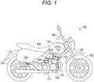
- Fig. 1 is a side view of a schematic entire configuration of a straddle type vehicle 100 including a clutch drive unit 220 according to the present invention.
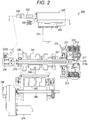
- Fig. 2 is a partial sectional view of a schematic configuration of a main portion of a power transmission device 200 in the straddle type vehicle 100 illustrated in Fig. 1 .
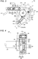
- Fig. 3 is a sectional view of a schematic internal structure of the clutch drive unit 220 from line 3-3 illustrated in Fig. 2 .
- Fig. 4 is a sectional view of the schematic internal structure of the clutch drive unit 220 from line 4-4 illustrated in Fig. 3 .
- the straddle type vehicle 100 is a so-called straddle type two-wheel motor vehicle (a so-called motorbike) on which a user rides in a straddling state.
- the straddle type vehicle 100 is configured such that a front wheel 103 is supported through a front fork 102 at a front end portion of a frame 101 and that a rear wheel 105 is supported through a swing arm 104 at a rear end portion of the frame 101.
- the frame 101 is formed to extend in a front-to-back direction of the straddle type vehicle 100.
- the front fork 102 is formed to rotate relative to the frame 101 in a right-to-left direction of the straddle type vehicle 100.
- handgrips 106 for steering the straddle type vehicle 100 in a traveling direction thereof are provided at an upper end portion of the front fork 102.
- each of a fuel tank 107 and a seat 108 is provided at the rear of the handgrips 106 with the fuel tank 107 and the seat 108 being supported on the frame 101.
- each of an engine 110 and the power transmission device 200 is provided below the fuel tank 107 with the engine 110 and the power transmission device 200 being supported on the frame 101.
- the engine 110 is a motor configured to generate rotary drive force by fuel combustion.
- the engine 110 is a so-called reciprocating engine.
- an air-fuel mixture of fuel and air is introduced into a cylinder (not shown) formed in a tubular shape.
- This air-fuel mixture is ignited and exploded by an ignition plug (not shown).
- a piston (not shown) reciprocates in the cylinder such that a crankshaft (not shown) coupled with the piston generates the rotary drive force.
- the rotary drive force of the crankshaft is transmitted to a clutch 210 of the power transmission device 200 through a primary drive gear attached to an end portion of the crankshaft.
- the engine 110 is assumed as a so-called four-stroke engine, but needless to say, may be a so-called two-stroke engine.
- the engine 110 is assumed as a single-cylinder engine provided with a single cylinder, but needless to say, may be an engine with two or more cylinders.
- the crankshaft is housed in a crank case 111.
- the crank case 111 is an outer housing forming a portion of the engine 110.
- the crank case 111 holds and houses, in addition to the crankshaft, some components forming the power transmission device 200, such as a transmission 240 and a shift drum 242.
- This crank case 111 is molded by die casting of aluminum alloy, and is configured separately from a cylinder block 112 configured to house the piston of the engine 110. Note that the crank case 111 may be configured integrally with the cylinder block 112, needless to say.
- the power transmission device 200 is a mechanical device configured to perform a gear change by a plurality of gear stages, thereby transmitting the rotary drive force generated by the engine 110.
- the power transmission device 200 mainly includes the clutch 210 and the transmission 240.
- the clutch 210 is arranged between the engine 110 and the transmission 240 on a transmission path of the rotary drive force generated by the engine 110.
- the clutch 210 is a mechanical device configured to transmit the rotary drive force generated by the engine 110 to the transmission 240 and to block such transmission.
- the clutch 210 is provided on one end side (the right side as viewed in the figure) of a main shaft 201 in a shaft shape extending from the transmission 240.
- the main shaft 201 is a component configured to rotate together with a clutch hub 214 to transmit the rotary drive force to the transmission 240.
- the main shaft 201 includes a shaft body formed in a hollow shape. Note that hatching is omitted in Fig. 2 .
- the clutch 210 includes, in a clutch housing 211, a plurality of friction plates 212 and a plurality of clutch plates 213.
- the clutch housing 211 is made of an aluminum alloy material, and is molded in a cylindrical shape with a bottom.
- the friction plates 212 and the clutch plates 213 are pressed against each other, or are separated from each other.
- Each friction plate 212 includes a ring body formed of a steel plate, an outer peripheral portion of the friction plate 212 being radially formed in a recessed-raised shape. Multiple small pieces of a friction material are bonded to both of plate surfaces of each ring body.
- each clutch plate 213 includes a ring body formed of a steel plate, an inner peripheral portion of the clutch plate 213 being radially formed in a recessed-raised shape.
- the friction plates 212 and the clutch plates 213 are held at the clutch housing 211 to be rotatably driven in association with rotary driving of the engine 110, and the clutch plates 213 are held at the clutch hub 214 coupled with the main shaft 201.
- the clutch housing 211 is configured in such a manner that an aluminum material is formed in a cylindrical shape with a bottom.
- the clutch housing 211 forms a portion of the housing of the clutch 210. Further, the clutch housing 211 holds, on an inner peripheral surface thereof, each of the multiple friction plates 212 by spline fitting in a state in which the friction plates 212 are displaceable along an axial direction of the clutch housing 211 and are rotatable together with the clutch housing 211.
- the clutch hub 214 is configured in such a manner that an aluminum material is formed in a substantially flange shape.
- the clutch hub 214 is arranged concentric with respect to the clutch housing 211.
- Many spline grooves are formed along an axial direction of the clutch hub 214 at an inner peripheral surface of the clutch hub 214.
- the main shaft 201 is spline-fitted to the spline grooves.
- a push rod 215 is provided to extend in an axial direction of the main shaft 201.
- One end side (the left side as viewed in the figure) of the push rod 215 in the main shaft 201 is coupled with the clutch drive unit 220 through a later-described slave cylinder 234.
- the push rod 215 slides along the axial direction of the main shaft 201 in the hollow portion of the main shaft 201 while pressing a pressure plate 216 through a push member 215a.
- the clutch hub 214 holds, on an outer peripheral surface thereof, each of the multiple clutch plates 213 by spline fitting in a state in which adjacent ones of the clutch plates 213 sandwiches the friction plate 212 and the clutch plates 213 are displaceable along the axial direction of the clutch hub 214 and are rotatable together with the clutch hub 214. Moreover, the pressure plate 216 is attached to the clutch hub 214 through a clutch spring 217.
- the pressure plate 216 is a component configured to press the friction plates 212 to bring the friction plates 212 and the clutch plates 213 into close contact with each other.
- the pressure plate 216 is configured in such a manner that an aluminum material is molded in a substantially discoid shape having the substantially same outer diameter as the outer diameter of the clutch plate 213.
- the clutch spring 217 is an elastic body configured to produce elastic pressing force for pressing the pressure plate 216 toward the clutch hub 214.
- the clutch spring 217 includes a coil spring (a compression spring) formed in such a manner that spring steel is wound in a spiral shape.
- the clutch 210 is filled with a predetermined amount of clutch oil (not shown).
- the clutch oil is mainly supplied to between the friction plate 212 and the clutch plate 213, thereby preventing absorption of friction heat generated between these plates and abrasion of the friction material. That is, the clutch 210 is a so-called multi-plate wet friction clutch device.
- the push rod 215 is pressed to the right side as viewed in the figure by the clutch drive unit 220, so that the friction plates 212 and the clutch plates 213 are separated from each other. In this manner, the clutch 210 is brought into a blocking state in which no drive force of the engine 110 is transmitted to the transmission 240.
- the push rod 215 is pulled in to the left side as viewed in the figure by a clutch actuator 231, so that the friction plates 212 and the clutch plates 213 are pushed against each other. In this manner, the clutch 210 is brought into a connection state in which the drive force of the engine 110 is transmitted to the transmission 240.
- the clutch drive unit 220 is a mechanical device configured to press the push rod 215 toward the pressure plate 216 side to switch the state of transmission of the drive force by the clutch 210 to the blocking state.
- the clutch drive unit 220 includes a crank arm 221.
- the crank arm 221 is a component for pressing a piston of a master cylinder 232 described later, and is configured in such a manner that a steel material or a sintered material is formed in a plate shape. More specifically, the crank arm 221 has, at an arm body 221a formed in a plat shape, each of a tubular portion 221b, a tooth portion 221c, an output pin 222, and a receiving pin 223.
- the arm body 221a is formed in such a deformed shape that the arm body 221a extends in a plate shape from a portion of an outer peripheral portion of the tubular portion 221b.
- the tubular portion 221b is a portion configured to rotatably support the crank arm 221 on a unit case 230 through a coupling shaft 224.
- the tubular portion 221b forms a hole penetrating the arm body 221a.
- a spline is formed at an inner peripheral surface of the tubular portion 221b, and the coupling shaft 224 is spline-fitted to this spline.
- the tooth portion 221c is a portion configured to receive the rotary drive force of the clutch actuator 231 through a transmission gear 226.
- the tooth portion 221 c is formed such that multiple raised teeth intermittently project along an arc at a portion of an end portion of the arm body 221a.
- the tooth portion 221c is formed to have a length corresponding to the range of rotation of the crank arm 221.
- the output pin 222 is provided on one side of the tooth portion 221c in two rotation directions of the crank arm 221, and the receiving pin 223 is provided on the other side.
- the output pin 222 is a circular columnar component configured to press an end portion of an output rod 227.
- the output pin 222 is configured such that a tubular collar is, in a state in which the output pin 222 is sandwiched between the arm body 221a and a pin holding arm 225, rotatably attached to an outer peripheral portion of a round bar-shaped pin body supported in a fixed manner.
- the receiving pin 223 is a round bar-shaped component configured to receive pressing force from an extendable body 228. Both end portions of the receiving pin 223 are each fitted to the arm body 221a and the pin holding arm 225, and are held in a fixed manner.
- the receiving pin 223 is provided at a position with a longer distance from the center of the tubular portion 221b as the center of rotation of the crank arm 221 than the output pin 222.
- a position is a position on the outside of the output pin 222 with respect to the center of rotation of the crank arm 221.
- the coupling shaft 224 is a round bar-shaped component configured to rotatably and integrally hold the crank arm 221 and the pin holding arm 225 on the unit case 230. Both end portions of the coupling shaft 224 are rotatably supported on the unit case 230 through bearings.
- a spline is formed at an outer peripheral portion of the coupling shaft 224, and each of the crank arm 221 and the pin holding arm 225 is spline-fitted to this spline.
- the pin holding arm 225 is a component configured to cooperate with the crank arm 221 to hold the receiving pin 223.
- the pin holding arm 225 is formed in a plate shape extending parallel to the crank arm 221 from the above-described spline-fitted coupling shaft 224 to sandwich the receiving pin 223.
- the transmission gear 226 is a mechanical element configured to decelerate the rotary drive force of the clutch actuator 231 to transmit such force to the tooth portion 221c.
- the transmission gear 226 includes a large gear configured to engage with a drive shaft of the clutch actuator 231, and a small gear provided concentric with respect to the large gear and configured to engage with the tooth portion 221c.
- the transmission gear 226 is rotatably supported on the unit case 230. Note that in Fig. 4 , a portion of the transmission gear 226 and a portion of the unit case 230 supporting the transmission gear 226 are indicated by chain double-dashed lines.
- the output rod 227 is a component configured to press the piston 232b of the master cylinder 232, and is configured in such a manner that a steel material is formed in a round bar shape.
- the output rod 227 is held on the unit case 230 in a state in which the output rod 227 is slidable along a sliding direction of the piston 232b of the master cylinder 232. That is, the output rod 227 is arranged between the piston 232b of the master cylinder 232 and the output pin 222, thereby transmitting pressing force between both components.
- the extendable body 228 is a component configured to cause the output pin 222 to press the piston 232b of the master cylinder 232 to maintain a clutch OFF state as the drive force blocking state in the clutch 210.
- the extendable body 228 mainly includes each of a lock spring 228a, a spring holder 228b, and a pressing body 228c.
- the lock spring 228a is an elastic body configured to produce elastic pressing force for pushing the pressing body 228c against the receiving pin 223, and includes a coil spring (a compression spring) formed in such a manner that spring steel is wound in a spiral shape.
- the lock spring 228a is set to have such strength that pressing force P allowing pressing moment PM to act on the crank arm 221 is generated.
- the pressing moment PM is greater than reactive force moment RM based on reactive force R from the clutch 210, the reactive force moment RM acting on the crank arm 221 through each of the push rod 215 and the output rod 227.
- the spring holder 228b is a component configured to hold the lock spring 228a in an extendable state and to hold the pressing body 228c in such a state that the pressing body 228c is slidable along an extension direction of the lock spring 228a. More specifically, the spring holder 228b is configured such that a portion of the spring holder 228b supporting one end portion of the lock spring 228a projects in a flange shape from an outer peripheral portion of a tubular body with a bottom, the tubular body slidably holding the pressing body 228c.
- the pressing body 228c is a component configured to transmit the pressing force of the lock spring 228a to the receiving pin 223. More specifically, the pressing body 228c is configured such that a portion of the pressing body 228c supporting the other end portion of the lock spring 228a is formed to project in a flange shape from an outer peripheral portion of a shaft portion sliding in the spring holder 228b with the pressing body 228c being pushed against the receiving pin 223. Moreover, the extendable body 228 is coupled with the crank arm 221 to rotate about the unit case 230 as the center of rotation.
- the extendable body 228 is provided such that a tip end portion of the spring holder 228b is, by the pressing force of the lock spring 228a, rotatably pushed against an outer peripheral surface of a holder receiving pin 229 provided at the unit case 230 and that a tip end portion of the pressing body 228c is, by the pressing force of the lock spring 228a, pushed against an outer peripheral surface of the receiving pin 223 to slide in a circumferential direction. That is, the extendable body 228 is provided in a stretched state between the receiving pin 223 and the holder receiving pin 229 by the extension force of the lock spring 228a.
- the extendable body 228 faces in such a direction that a pressing direction of the lock spring 228a is toward the center of rotation of the crank arm 221. Further, the extendable body 228 rotates in each of the clockwise and counterclockwise directions with respect to such a direction by an amount corresponding to the amount of rotation of the crank arm 221.
- the unit case 230 is a component forming an outer housing of the clutch drive unit 220.
- the unit case 230 is formed in such a hollow shape that the entirety of each of the crank arm 221, the pin holding arm 225, the transmission gear 226, the output rod 227, and the extendable body 228 is housed.
- the unit case 230 includes a body case 230a and a lid case 230b molded by die casting of aluminum alloy.
- the unit case 230 is attached to the frame 101 below the crank case 111 and the seat 108.
- the body case 230a is a component configured to support and house each of the crank arm 221, the pin holding arm 225, the transmission gear 226, the output rod 227, and the extendable body 228, and is formed in such a recessed shape that these components can be housed.
- the lid case 230b is component configured to support each of the crank arm 221, the pin holding arm 225, the transmission gear 226, the output rod 227, and the extendable body 228 while closing an opening portion of the body case 230a.
- the lid case 230b is formed substantially in such a plate shape that the opening portion of the body case 230a can be covered.
- the lid case 230b is attached to the body case 230a with not-shown bolts. Moreover, each of the clutch actuator 231, the master cylinder 232, and an angle sensor 235 is attached to an outer surface of the lid case 230b.
- the clutch actuator 231 is a power source configured to switch the state of transmission of the drive force in the clutch 210 to the blocking state.
- the clutch actuator 231 includes an electric motor whose operation is controlled by a not-shown transmission control unit (TCU).
- TCU transmission control unit
- the clutch actuator 231 is attached to the unit case 230 such that a drive gear 231a provided at the drive shaft engages with the transmission gear 226.
- the TCU includes a microcomputer with a CPU, a ROM, a RAM, and the like.
- the TCU is configured to control, in an integrated manner, operation of the power transmission device 200 according to a not-shown control program stored in the ROM and the like in advance. More specifically, the TCU executes control of connection and disconnection of the clutch 210 and control of each type of gear change operation including shift-up and shift-down in the transmission 240. In this case, the TCU controls operation of the clutch actuator 231 by PWM control.
- the master cylinder 232 is a mechanical device configured to generate hydraulic pressure for pressing the pressure plate 216 against the elastic force of the clutch spring 217 in the clutch 210.
- the master cylinder 232 mainly includes each of a cylinder 232a, the piston 232b, and a return spring 232c.
- the cylinder 232a slidably supports the piston 232b in such a state that hydraulic oil (not shown) supplied from a not-shown reservoir tank and the return spring 232c are housed.
- the cylinder 232a is connected to the slave cylinder 234 through a pipe 233.
- the piston 232b is a round bar-shaped component configured to compress the hydraulic oil in the cylinder 232a. One end portion of the piston 232b faces the hydraulic oil. The other end portion of the piston 232b is connected to the output pin 222.
- the return spring 232c is a coil spring arranged in the cylinder 232a and configured to push the piston 232b back to the output pin 222 to release a hydraulic oil compression state.
- the slave cylinder 234 is hydraulic equipment configured to generate hydraulic pressure based on the hydraulic pressure supplied from the master cylinder 232, thereby pressing the push rod 215 toward the pressure plate 216 side.
- the angle sensor 235 is a detector configured to detect the rotation angle position of the crank arm 221, thereby outputting such a position to the TCU.
- the angle sensor 235 is connected to a tip end portion of the coupling shaft 224 penetrating the unit case 230.
- the transmission 240 is a mechanical device for performing the gear change by the multiple gear stages (e.g., a five-speed gear change) to transmit the rotary drive force generated from the engine 110 to the rear wheel 105.
- a plurality of gear trains 241 is provided in the transmission 240.
- the multiple gear trains 241 form the multiple gear stages with different transmission gear ratios from one another between the main shaft 201 connected to the crankshaft of the engine 110 through the clutch 210 and a not-shown counter shaft extending parallel to the main shaft 201 and connected to the rear wheel 105. That is, in the transmission 240, the gear trains 241 are coupled or separated in a dog clutch manner, thereby forming the gear stages.
- the gear trains 241 are recombined by a shift fork 243 in this case.
- the shift fork 243 reciprocatively displaces along the main shaft 201 and the counter shaft by rotary driving of the shift drum 242.
- the shift drum 242 is a circular columnar component configured to reciprocatively displace the shift fork 243 along the main shaft 201 and the counter shaft.
- the shift drum 242 is rotatably driven by a shift actuator 244.
- the shift actuator 244 is a drive source configured to rotatably drive the shift drum 242, and includes an electric motor whose operation is controlled by the transmission control unit (TCU).
- the shift actuator 244 is coupled with the shift drum 242 through a shift shaft 245.
- an angle sensor 246 is provided at the shift drum 242. The angle sensor 246 is configured to detect the rotation angle of the shift drum 242 to output such an angle to the TCU.
- the straddle type vehicle 100 travels while a change in the gear stages in the transmission 240, i.e., shift-up or shift-down, is being performed based on shift operation by a driver and determination by the TCU.
- the TCU controls operation of the clutch drive unit 220 to selectively switch the clutch 210 between the drive force transmission state and the drive force blocking state.
- the TCU rotatably drives the clutch actuator 231 in the direction of generating the hydraulic pressure by the master cylinder 232 in a case where the clutch 210 transitions from the drive force transmission state to the drive force blocking state.
- the crank arm 221 rotates, as indicated by a dashed arrow in Fig. 3 , counterclockwise (leftward as viewed in the figure) through rotary driving of the transmission gear 226.
- the output pin 222 presses the output rod 227, and therefore, the hydraulic pressure is generated at the master cylinder 232.
- the hydraulic pressure generated at the master cylinder 232 is transmitted to the push rod 215 through the pipe 233 and the slave cylinder 234, thereby displacing the push rod 215 toward the pressure plate 216 side.
- the state of close contact among the friction plates 212 and the clutch plates 213 by the pressure plate 216 is released, and the friction plates 212 and the clutch plates 213 are separated from each other. Accordingly, the clutch 210 transitions to the clutch OFF state.
- the extendable body 228 in the clutch drive unit 220 is coupled with the crank arm 221, and therefore, rotates about the holder receiving pin 229 in association with rotation of the crank arm 221 as illustrated in each of Figs. 5 and 6 .
- the extendable body 228 rotates, with respect to the direction in which the pressing direction of the extendable body 228 is toward the center of rotation of the crank arm 221, in a direction against (toward) the direction of action of the reactive force moment RM acting on the crank arm 221.
- the pressing moment PM in the same direction as the rotation direction of the crank arm 221 acts on the crank arm 221.
- the pressing moment PM is generated by a component of the pressing force P of the extendable body 228, the component acting in the direction of tangent of the rotation direction of the crank arm 221.
- the clutch actuator 23 a burden against the reactive force R acting on the crank arm 221 from the clutch 210, specifically a burden against the reactive force moment RM based on the elastic force of the clutch spring 217, is reduced.
- the TCU drives the clutch actuator 231 until the crank arm 221 reaches the rotation limit thereof, i.e., until the crank arm 221 reaches such a rotation position that the clutch 210 is fully brought into the clutch OFF, and then, stops the clutch actuator 231.
- the extendable body 228 includes the lock spring 228a configured to produce the pressing force P for generating the pressing moment PM at the crank arm 221.
- the pressing moment PM acts in the direction opposite to the reactive force moment RM acting on the crank arm 221, and is greater than the reactive force moment RM.
- the extendable body 228 includes the lock spring 228a configured to produce greater pressing force than force for contracting the lock spring 228a of the extendable body 228 by the crank arm 221 by means of the pressing force of the clutch spring 217 of the clutch 210.
- the clutch drive unit 220 can maintain the state of pressing the master cylinder 232 by the pressing force P of the extendable body 228 even in a case where rotary driving of the clutch actuator 231 is stopped.
- the force acting on the crank arm 221 through the output rod 227 also includes, needless to say, other types of force than the force of the clutch spring 217, such as the reactive force of the return spring 232c.
- the TCU rotatably drives the clutch actuator 231 in the direction of releasing the hydraulic pressure generated by the master cylinder 232, i.e., in the opposite direction of the above-described direction.
- the crank arm 221 rotates clockwise (rightward as viewed in the figure) through rotary driving of the transmission gear 226. Accordingly, the force of pressing the output rod 227 by the output pin 222 is weakened, and therefore, the hydraulic pressure generated by the master cylinder 232 is released.
- the pressure plate 216 brings, by the pressing force of the clutch spring 217, the friction plates 212 and the clutch plates 213 into close contact with each other, and the clutch 210 transitions to a clutch ON state. Further, the push rod 215 retracts toward the slave cylinder 234 side.
- the extendable body 228 in the clutch drive unit 220 is coupled with the crank arm 221, and therefore, rotates toward the side in which the pressing direction of the extendable body 228 is toward the center of rotation of the crank arm 221. Accordingly, the pressing moment acting on the crank arm 221 decreases as the crank arm 221 rotates. This pressing moment becomes minimum ("zero" in theory) when the crank arm 221 is in the direction in which the pressing direction of the extendable body 228 is toward the center of rotation of the crank arm 221.
- the TCU drives the clutch actuator 231 until the crank arm 221 reaches the rotation limit thereof ( ⁇ 2 in Fig. 7 ), i.e., until the crank arm 221 reaches such a rotation position that the clutch 210 is turned to the clutch ON, and then, stops the clutch actuator 231.
- the extendable body 228 is at a position having rotated, with respect to the direction in which the pressing direction of the extendable body 228 is toward the center of rotation of the crank arm 221, in a direction along (following) the action direction of the reactive force moment RM acting on the crank arm 221.
- the clutch drive unit 220 can reliably maintain the transmission state (also referred to as "clutch ON") of the clutch even after operation of the clutch actuator has been stopped after transition to the drive force transmission state in the clutch 210.
- the clutch drive unit 220 starts, in subsequent clutch OFF operation, rotating from the position having rotated in the side along the action direction of the reactive force moment RM, to the side in which the pressing direction is a direction toward the center of rotation of the crank arm 221.
- the TCU can grasp the level of the drive force transmission state and drive force blocking state of the clutch 210 based on a detection signal of the angle sensor 235 connected to the coupling shaft 224.
- the TCU can grasp the level of the transmission state with a higher resolution in a shorter time, thereby reflecting such a state in clutch control.
- the extendable body 228 having the elastic body configured to produce the pressing force P is, in the clutch drive unit 220, rotatably supported within the range in the direction toward the center of rotation of the crank arm 221 and the direction against the reactive force moment RM based on the reactive force R acting on the crank arm 221 from the clutch 210, and therefore, provides the pressing force P to the crank arm 221.
- the extendable body 228 provides the crank arm 221 with such pressing force P that the pressing moment PM acting on the crank arm 221 is greater than the reactive force moment RM.
- the extendable body 228 causes the pressing moment PM greater than the reactive force moment RM to act on the crank arm 221 in the direction against the reactive force moment RM. Consequently, the clutch drive unit 220 can maintain the clutch OFF state of the clutch 210 even after operation of the clutch actuator 231 has been stopped. As a result, the clutch drive unit 220 can reduce power consumption of the clutch actuator 231, as well as realizing reduction in the size and weight of the device configuration.
- the clutch drive unit 220 is configured such that when the clutch 210 is in the clutch ON state, the pressing force P of the extendable body 228 is at the position ( ⁇ 2 in Fig. 7 ) having rotated to the downstream side in action of the reactive force moment RM with respect to the direction in which the pressing force P of the extendable body 228 is toward the center of rotation of the crank arm 221.
- the clutch drive unit 220 can be configured such that when the clutch 210 is in the clutch ON state, the pressing force P of the extendable body 228 is positioned in the direction in which the pressing force P of the extendable body 228 is toward the center of rotation of the crank arm 221 or the pressing force P of the extendable body 228 is at a position having rotated to the upstream side (a 01 side in Fig. 6 ) in action of the reactive force moment RM with respect to the direction in which the pressing force P of the extendable body 228 is toward the center of rotation of the crank arm 221.
- the clutch drive unit 220 can maintain the clutch ON state by the reactive force R from the clutch 210 side.
- the TCU can grasp the level of the drive force transmission state and drive force blocking state of the clutch 210 based on the detection signal of the angle sensor 235 connected to the coupling shaft 224.
- the angle sensor 235 may be at such a position that the rotation angle of the crank arm 221 can be detected.
- the angle sensor 235 may be provided at other locations than the coupling shaft 224, such as a drive shaft of the transmission gear 226 or the clutch actuator 231.
- the angle sensor 235 can be omitted from the clutch drive unit 220 in the case of providing the angle sensor 235 at the clutch 210 side.
- the clutch 210 is configured such that the push rod 215 presses the pressure plate 216 to block transmission of the drive force from the engine 110.
- the clutch 210 can be configured such that the push rod 215 presses the pressure plate 216 to transmit the drive force from the engine 110.
- the extendable body 228 has the lock spring 228a including the coil spring.
- the extendable body 228 may be rotatably provided at the crank arm 221 within the range in the direction in which the pressing direction of the pressing force P is toward the center of rotation of the crank arm 221 and the direction against the reactive force moment RM based on the reactive force R acting on the crank arm 221 from the clutch 210, and may have the elastic body configured to cause the pressing moment PM greater than the reactive force moment RM to act on the crank arm 221 in the opposite direction of the reactive force moment RM.
- the extendable body 228 can include, instead of the lock spring 228a, a hydraulic cylinder or an air cylinder.
- the straddle type vehicle 100 is configured as the two-wheel motor vehicle (the so-called motorbike).
- the straddle type vehicle 100 can be broadly applied to self-propelled vehicles in a form in which a user is seated on the seat 108 in a straddling state.
- the straddle type vehicle 100 is also applicable to a four-wheel buggy.
Description
- The present invention relates to a clutch drive unit mounted on a straddle type vehicle such as a motorcycle or a four-wheel buggy car and to a straddle type vehicle including the clutch drive unit.
- Typically, a power transmission device is, at a self-propelled vehicle such as a motorcycle or a four-wheel buggy car, provided for transmitting drive force generated by an engine (a motor) to a drive wheel. The power transmission device is, while being connected or disconnected to/from the crankshaft, a mechanical device configured to change the number of rotations of a crankshaft of the engine to transmit the number of rotations to the drive wheel, and mainly includes a clutch and a transmission.
- The clutch described herein is a mechanical device configured to transmit rotary drive force of the crankshaft of the engine to a transmission side while being connected or disconnected to/from the crankshaft. Moreover, the transmission is a mechanical device configured to change the number of rotations of the crankshaft of the engine by a plurality of gear stages formed by a combination of a plurality of gears, thereby transmitting the number of rotations to a drive wheel side.
- In this case, the clutch is configured to selectively switch between transmission and blocking of rotary drive force from the engine in such a manner that a clutch drive unit including an electric motor drives a push rod to move back and forth. For example, a clutch actuator as a clutch drive unit disclosed in
JP-A-2007-285452 EP 1 669 623 A1 ,US 2007/0240958 A1 orUS 4 852 419 A1 includes an assist spring configured to assist rotary drive force of a clutch motor. - However, in the clutch drive units described in those prior art documents, a drive force blocking state (also referred to as "clutch OFF") in a clutch is maintained by continuation of an electric motor rotary driving state, and for this reason, the following problems are caused. Power consumption of an electric motor is great. Further, a high-power electric motor is needed. This leads to an increase in the size and weight of the clutch drive unit.
- The present invention has been made to deal with the above-described problems. An object of the present invention is to provide the following clutch drive unit and the following straddle type vehicle including the clutch drive unit. According to this clutch drive unit, power consumption of an electric motor can be reduced, as well as realizing reduction in the size and weight of a device configuration.
- In order to achieve the above object, the present invention provides a clutch drive unit according to claim 1.
- According to the the present invention, the extendable body having the elastic body configured to produce the pressing force is, in the clutch drive unit, rotatably supported within the range in the direction toward the center of rotation of the crank arm and the direction against the reactive force moment based on the reactive force acting on the crank arm from the clutch, and provides the pressing force to the crank arm. In this case, the extendable body provides the crank arm with such pressing force that the pressing moment acting on the crank arm is greater than the reactive force moment. Thus, in the clutch drive unit, the extendable body causes the pressing moment greater than the reactive force moment to act on the crank arm in the direction against the reactive force moment. Consequently, the clutch drive unit can maintain a clutch OFF state (or a clutch ON state) of the clutch even after operation of the clutch actuator has been stopped. As a result, the clutch drive unit can reduce power consumption of the clutch actuator, as well as realizing reduction in the size and weight of the device configuration.
- Note that in this case, the clutch has the push rod, and can be configured to transmit the drive force from the engine to the transmission or to block such transmission. The push rod displaces friction plates to be rotatably driven by the drive force transmitted from the engine and clutch plates arranged facing the friction plates to transmit the drive force to the transmission against elastic force of a clutch spring for pushing the friction plates and the clutch plates against each other or separating the friction plates and the clutch plates from each other. In this manner, the push rod separates these plates from each other, or pushes these plates against each other.
- Moreover, another feature of the present invention is that in the clutch drive unit, the extendable body also rotates, with respect to the direction in which the pressing direction is toward the center of rotation of the crank arm, in a direction in which the reactive force moment acts.
- According to another feature of the present invention configured as described above, the extendable body also rotates, in the clutch drive unit, in the direction in which the reactive force moment acts with respect to the direction in which the extendable body faces toward the center of rotation of the crank arm. Thus, the clutch drive unit can reliably maintain the transmission state (also referred to as "clutch ON") of the clutch even after operation of the clutch actuator has been stopped after transition to the drive force transmission state (also referred to as "clutch ON") in the clutch.
- Moreover, still another feature of the present invention is that an angle sensor configured to detect the amount of rotation of the crank arm is, in the clutch drive unit, further provided on the center shaft of rotation of the crank arm.
- According to another feature of the present invention configured as described above, the angle sensor configured to detect the amount of rotation of the crank arm is, in the clutch drive unit, provided on the center shaft of rotation of the crank arm. Thus, the level of the drive force transmission state in the clutch (in other words, the level of the blocking state) can be specified by the amount of rotation of the crank arm. Thus, the level of the transmission state can be grasped with a higher resolution in a shorter time, and can be reflected in clutch control.
- Moreover, the present invention can be not only implemented as the invention relating to the clutch drive unit, but also can be implemented as the invention relating to a straddle type vehicle including the clutch drive unit according to any one of claims 1 to 5. With this configuration, working effects similar to those of the above-described clutch drive unit can be expected as well.
-
-
Fig. 1 is a side view of a schematic entire configuration of a straddle type vehicle including a clutch drive unit according to the present invention. -
Fig. 2 is a partial sectional view of a schematic configuration of a main portion of a power transmission device in the straddle type vehicle illustrated inFig. 1 . -
Fig. 3 is a partially-broken sectional view of a schematic internal structure of the clutch drive unit from line 3-3 illustrated inFig. 2 . -
Fig. 4 is a sectional view of the schematic internal structure of the clutch drive unit from line 4-4 illustrated inFig. 3 . -
Fig. 5 is a partially-broken sectional view in an operation state when the clutch drive unit illustrated inFig. 3 causes a clutch OFF. -
Fig. 6 is a view for describing a mechanical relationship between a crank arm and an extendable body illustrated inFig. 3 at the time of the clutch OFF. -
Fig. 7 is a view for describing the mechanical relationship between the crank arm and the extendable body illustrated inFig. 3 at the time of a clutch ON. - One embodiment of a clutch drive unit and a straddle type vehicle including the clutch drive unit according to the present invention will be described below with reference to the drawings.
Fig. 1 is a side view of a schematic entire configuration of astraddle type vehicle 100 including aclutch drive unit 220 according to the present invention. Moreover,Fig. 2 is a partial sectional view of a schematic configuration of a main portion of apower transmission device 200 in thestraddle type vehicle 100 illustrated inFig. 1 . Further,Fig. 3 is a sectional view of a schematic internal structure of theclutch drive unit 220 from line 3-3 illustrated inFig. 2 . In addition,Fig. 4 is a sectional view of the schematic internal structure of theclutch drive unit 220 from line 4-4 illustrated inFig. 3 . Thestraddle type vehicle 100 is a so-called straddle type two-wheel motor vehicle (a so-called motorbike) on which a user rides in a straddling state. - The
straddle type vehicle 100 is configured such that afront wheel 103 is supported through afront fork 102 at a front end portion of aframe 101 and that arear wheel 105 is supported through aswing arm 104 at a rear end portion of theframe 101. Theframe 101 is formed to extend in a front-to-back direction of thestraddle type vehicle 100. In this case, thefront fork 102 is formed to rotate relative to theframe 101 in a right-to-left direction of thestraddle type vehicle 100. Further,handgrips 106 for steering thestraddle type vehicle 100 in a traveling direction thereof are provided at an upper end portion of thefront fork 102. - Moreover, in the
straddle type vehicle 100, each of afuel tank 107 and aseat 108 is provided at the rear of thehandgrips 106 with thefuel tank 107 and theseat 108 being supported on theframe 101. Further, in thestraddle type vehicle 100, each of anengine 110 and thepower transmission device 200 is provided below thefuel tank 107 with theengine 110 and thepower transmission device 200 being supported on theframe 101. - The
engine 110 is a motor configured to generate rotary drive force by fuel combustion. Specifically, theengine 110 is a so-called reciprocating engine. In theengine 110, an air-fuel mixture of fuel and air is introduced into a cylinder (not shown) formed in a tubular shape. This air-fuel mixture is ignited and exploded by an ignition plug (not shown). Accordingly, a piston (not shown) reciprocates in the cylinder such that a crankshaft (not shown) coupled with the piston generates the rotary drive force. The rotary drive force of the crankshaft is transmitted to aclutch 210 of thepower transmission device 200 through a primary drive gear attached to an end portion of the crankshaft. - Note that in the present embodiment, the
engine 110 is assumed as a so-called four-stroke engine, but needless to say, may be a so-called two-stroke engine. Moreover, in the present embodiment, theengine 110 is assumed as a single-cylinder engine provided with a single cylinder, but needless to say, may be an engine with two or more cylinders. - The crankshaft is housed in a crank
case 111. The crankcase 111 is an outer housing forming a portion of theengine 110. The crankcase 111 holds and houses, in addition to the crankshaft, some components forming thepower transmission device 200, such as atransmission 240 and ashift drum 242. This crankcase 111 is molded by die casting of aluminum alloy, and is configured separately from acylinder block 112 configured to house the piston of theengine 110. Note that the crankcase 111 may be configured integrally with thecylinder block 112, needless to say. - The
power transmission device 200 is a mechanical device configured to perform a gear change by a plurality of gear stages, thereby transmitting the rotary drive force generated by theengine 110. Thepower transmission device 200 mainly includes the clutch 210 and thetransmission 240. - The clutch 210 is arranged between the
engine 110 and thetransmission 240 on a transmission path of the rotary drive force generated by theengine 110. The clutch 210 is a mechanical device configured to transmit the rotary drive force generated by theengine 110 to thetransmission 240 and to block such transmission. As specifically illustrated inFig. 3 , the clutch 210 is provided on one end side (the right side as viewed in the figure) of amain shaft 201 in a shaft shape extending from thetransmission 240. Themain shaft 201 is a component configured to rotate together with aclutch hub 214 to transmit the rotary drive force to thetransmission 240. Themain shaft 201 includes a shaft body formed in a hollow shape. Note that hatching is omitted inFig. 2 . - The clutch 210 includes, in a
clutch housing 211, a plurality offriction plates 212 and a plurality ofclutch plates 213. Theclutch housing 211 is made of an aluminum alloy material, and is molded in a cylindrical shape with a bottom. Thefriction plates 212 and theclutch plates 213 are pressed against each other, or are separated from each other. Eachfriction plate 212 includes a ring body formed of a steel plate, an outer peripheral portion of thefriction plate 212 being radially formed in a recessed-raised shape. Multiple small pieces of a friction material are bonded to both of plate surfaces of each ring body. - On the other hand, each
clutch plate 213 includes a ring body formed of a steel plate, an inner peripheral portion of theclutch plate 213 being radially formed in a recessed-raised shape. Of thesefriction plates 212 and theclutch plates 213, thefriction plates 212 are held at theclutch housing 211 to be rotatably driven in association with rotary driving of theengine 110, and theclutch plates 213 are held at theclutch hub 214 coupled with themain shaft 201. - The
clutch housing 211 is configured in such a manner that an aluminum material is formed in a cylindrical shape with a bottom. Theclutch housing 211 forms a portion of the housing of the clutch 210. Further, theclutch housing 211 holds, on an inner peripheral surface thereof, each of themultiple friction plates 212 by spline fitting in a state in which thefriction plates 212 are displaceable along an axial direction of theclutch housing 211 and are rotatable together with theclutch housing 211. - The
clutch hub 214 is configured in such a manner that an aluminum material is formed in a substantially flange shape. Theclutch hub 214 is arranged concentric with respect to theclutch housing 211. Many spline grooves are formed along an axial direction of theclutch hub 214 at an inner peripheral surface of theclutch hub 214. Themain shaft 201 is spline-fitted to the spline grooves. In the hollow portion of themain shaft 201, apush rod 215 is provided to extend in an axial direction of themain shaft 201. - One end side (the left side as viewed in the figure) of the
push rod 215 in themain shaft 201 is coupled with theclutch drive unit 220 through a later-describedslave cylinder 234. By hydraulic pressure by driving of theclutch drive unit 220, thepush rod 215 slides along the axial direction of themain shaft 201 in the hollow portion of themain shaft 201 while pressing apressure plate 216 through apush member 215a. - The
clutch hub 214 holds, on an outer peripheral surface thereof, each of the multipleclutch plates 213 by spline fitting in a state in which adjacent ones of theclutch plates 213 sandwiches thefriction plate 212 and theclutch plates 213 are displaceable along the axial direction of theclutch hub 214 and are rotatable together with theclutch hub 214. Moreover, thepressure plate 216 is attached to theclutch hub 214 through aclutch spring 217. - The
pressure plate 216 is a component configured to press thefriction plates 212 to bring thefriction plates 212 and theclutch plates 213 into close contact with each other. Thepressure plate 216 is configured in such a manner that an aluminum material is molded in a substantially discoid shape having the substantially same outer diameter as the outer diameter of theclutch plate 213. Theclutch spring 217 is an elastic body configured to produce elastic pressing force for pressing thepressure plate 216 toward theclutch hub 214. Theclutch spring 217 includes a coil spring (a compression spring) formed in such a manner that spring steel is wound in a spiral shape. - The clutch 210 is filled with a predetermined amount of clutch oil (not shown). The clutch oil is mainly supplied to between the
friction plate 212 and theclutch plate 213, thereby preventing absorption of friction heat generated between these plates and abrasion of the friction material. That is, the clutch 210 is a so-called multi-plate wet friction clutch device. - Thus, in the clutch 210, the
push rod 215 is pressed to the right side as viewed in the figure by theclutch drive unit 220, so that thefriction plates 212 and theclutch plates 213 are separated from each other. In this manner, the clutch 210 is brought into a blocking state in which no drive force of theengine 110 is transmitted to thetransmission 240. On the other hand, in the clutch 210, thepush rod 215 is pulled in to the left side as viewed in the figure by aclutch actuator 231, so that thefriction plates 212 and theclutch plates 213 are pushed against each other. In this manner, the clutch 210 is brought into a connection state in which the drive force of theengine 110 is transmitted to thetransmission 240. - The
clutch drive unit 220 is a mechanical device configured to press thepush rod 215 toward thepressure plate 216 side to switch the state of transmission of the drive force by the clutch 210 to the blocking state. Theclutch drive unit 220 includes acrank arm 221. - The
crank arm 221 is a component for pressing a piston of amaster cylinder 232 described later, and is configured in such a manner that a steel material or a sintered material is formed in a plate shape. More specifically, thecrank arm 221 has, at anarm body 221a formed in a plat shape, each of atubular portion 221b, atooth portion 221c, anoutput pin 222, and a receivingpin 223. - The
arm body 221a is formed in such a deformed shape that thearm body 221a extends in a plate shape from a portion of an outer peripheral portion of thetubular portion 221b. Thetubular portion 221b is a portion configured to rotatably support thecrank arm 221 on aunit case 230 through acoupling shaft 224. Thetubular portion 221b forms a hole penetrating thearm body 221a. A spline is formed at an inner peripheral surface of thetubular portion 221b, and thecoupling shaft 224 is spline-fitted to this spline. - The
tooth portion 221c is a portion configured to receive the rotary drive force of theclutch actuator 231 through atransmission gear 226. Thetooth portion 221 c is formed such that multiple raised teeth intermittently project along an arc at a portion of an end portion of thearm body 221a. In this case, thetooth portion 221c is formed to have a length corresponding to the range of rotation of thecrank arm 221. Theoutput pin 222 is provided on one side of thetooth portion 221c in two rotation directions of thecrank arm 221, and the receivingpin 223 is provided on the other side. - The
output pin 222 is a circular columnar component configured to press an end portion of anoutput rod 227. Theoutput pin 222 is configured such that a tubular collar is, in a state in which theoutput pin 222 is sandwiched between thearm body 221a and apin holding arm 225, rotatably attached to an outer peripheral portion of a round bar-shaped pin body supported in a fixed manner. The receivingpin 223 is a round bar-shaped component configured to receive pressing force from anextendable body 228. Both end portions of the receivingpin 223 are each fitted to thearm body 221a and thepin holding arm 225, and are held in a fixed manner. According to the invention, the receivingpin 223 is provided at a position with a longer distance from the center of thetubular portion 221b as the center of rotation of thecrank arm 221 than theoutput pin 222. In other words, such a position is a position on the outside of theoutput pin 222 with respect to the center of rotation of thecrank arm 221. - The
coupling shaft 224 is a round bar-shaped component configured to rotatably and integrally hold thecrank arm 221 and thepin holding arm 225 on theunit case 230. Both end portions of thecoupling shaft 224 are rotatably supported on theunit case 230 through bearings. A spline is formed at an outer peripheral portion of thecoupling shaft 224, and each of thecrank arm 221 and thepin holding arm 225 is spline-fitted to this spline. - The
pin holding arm 225 is a component configured to cooperate with thecrank arm 221 to hold the receivingpin 223. Thepin holding arm 225 is formed in a plate shape extending parallel to thecrank arm 221 from the above-described spline-fittedcoupling shaft 224 to sandwich the receivingpin 223. Thetransmission gear 226 is a mechanical element configured to decelerate the rotary drive force of theclutch actuator 231 to transmit such force to thetooth portion 221c. Thetransmission gear 226 includes a large gear configured to engage with a drive shaft of theclutch actuator 231, and a small gear provided concentric with respect to the large gear and configured to engage with thetooth portion 221c. Thetransmission gear 226 is rotatably supported on theunit case 230. Note that inFig. 4 , a portion of thetransmission gear 226 and a portion of theunit case 230 supporting thetransmission gear 226 are indicated by chain double-dashed lines. - The
output rod 227 is a component configured to press thepiston 232b of themaster cylinder 232, and is configured in such a manner that a steel material is formed in a round bar shape. Theoutput rod 227 is held on theunit case 230 in a state in which theoutput rod 227 is slidable along a sliding direction of thepiston 232b of themaster cylinder 232. That is, theoutput rod 227 is arranged between thepiston 232b of themaster cylinder 232 and theoutput pin 222, thereby transmitting pressing force between both components. - The
extendable body 228 is a component configured to cause theoutput pin 222 to press thepiston 232b of themaster cylinder 232 to maintain a clutch OFF state as the drive force blocking state in the clutch 210. Theextendable body 228 mainly includes each of alock spring 228a, aspring holder 228b, and apressing body 228c. - The
lock spring 228a is an elastic body configured to produce elastic pressing force for pushing thepressing body 228c against the receivingpin 223, and includes a coil spring (a compression spring) formed in such a manner that spring steel is wound in a spiral shape. In this case, thelock spring 228a is set to have such strength that pressing force P allowing pressing moment PM to act on thecrank arm 221 is generated. The pressing moment PM is greater than reactive force moment RM based on reactive force R from the clutch 210, the reactive force moment RM acting on thecrank arm 221 through each of thepush rod 215 and theoutput rod 227. - The
spring holder 228b is a component configured to hold thelock spring 228a in an extendable state and to hold thepressing body 228c in such a state that thepressing body 228c is slidable along an extension direction of thelock spring 228a. More specifically, thespring holder 228b is configured such that a portion of thespring holder 228b supporting one end portion of thelock spring 228a projects in a flange shape from an outer peripheral portion of a tubular body with a bottom, the tubular body slidably holding thepressing body 228c. - The
pressing body 228c is a component configured to transmit the pressing force of thelock spring 228a to the receivingpin 223. More specifically, thepressing body 228c is configured such that a portion of thepressing body 228c supporting the other end portion of thelock spring 228a is formed to project in a flange shape from an outer peripheral portion of a shaft portion sliding in thespring holder 228b with thepressing body 228c being pushed against the receivingpin 223. Moreover, theextendable body 228 is coupled with thecrank arm 221 to rotate about theunit case 230 as the center of rotation. - Specifically, the
extendable body 228 is provided such that a tip end portion of thespring holder 228b is, by the pressing force of thelock spring 228a, rotatably pushed against an outer peripheral surface of aholder receiving pin 229 provided at theunit case 230 and that a tip end portion of thepressing body 228c is, by the pressing force of thelock spring 228a, pushed against an outer peripheral surface of the receivingpin 223 to slide in a circumferential direction. That is, theextendable body 228 is provided in a stretched state between the receivingpin 223 and theholder receiving pin 229 by the extension force of thelock spring 228a. - With this configuration, the
extendable body 228 faces in such a direction that a pressing direction of thelock spring 228a is toward the center of rotation of thecrank arm 221. Further, theextendable body 228 rotates in each of the clockwise and counterclockwise directions with respect to such a direction by an amount corresponding to the amount of rotation of thecrank arm 221. - The
unit case 230 is a component forming an outer housing of theclutch drive unit 220. Theunit case 230 is formed in such a hollow shape that the entirety of each of thecrank arm 221, thepin holding arm 225, thetransmission gear 226, theoutput rod 227, and theextendable body 228 is housed. In the present embodiment, theunit case 230 includes abody case 230a and alid case 230b molded by die casting of aluminum alloy. Theunit case 230 is attached to theframe 101 below the crankcase 111 and theseat 108. - The
body case 230a is a component configured to support and house each of thecrank arm 221, thepin holding arm 225, thetransmission gear 226, theoutput rod 227, and theextendable body 228, and is formed in such a recessed shape that these components can be housed. Thelid case 230b is component configured to support each of thecrank arm 221, thepin holding arm 225, thetransmission gear 226, theoutput rod 227, and theextendable body 228 while closing an opening portion of thebody case 230a. Thelid case 230b is formed substantially in such a plate shape that the opening portion of thebody case 230a can be covered. - The
lid case 230b is attached to thebody case 230a with not-shown bolts. Moreover, each of theclutch actuator 231, themaster cylinder 232, and anangle sensor 235 is attached to an outer surface of thelid case 230b. - The
clutch actuator 231 is a power source configured to switch the state of transmission of the drive force in the clutch 210 to the blocking state. Theclutch actuator 231 includes an electric motor whose operation is controlled by a not-shown transmission control unit (TCU). Theclutch actuator 231 is attached to theunit case 230 such that adrive gear 231a provided at the drive shaft engages with thetransmission gear 226. - The TCU includes a microcomputer with a CPU, a ROM, a RAM, and the like. The TCU is configured to control, in an integrated manner, operation of the
power transmission device 200 according to a not-shown control program stored in the ROM and the like in advance. More specifically, the TCU executes control of connection and disconnection of the clutch 210 and control of each type of gear change operation including shift-up and shift-down in thetransmission 240. In this case, the TCU controls operation of theclutch actuator 231 by PWM control. - The
master cylinder 232 is a mechanical device configured to generate hydraulic pressure for pressing thepressure plate 216 against the elastic force of theclutch spring 217 in the clutch 210. Themaster cylinder 232 mainly includes each of acylinder 232a, thepiston 232b, and areturn spring 232c. Thecylinder 232a slidably supports thepiston 232b in such a state that hydraulic oil (not shown) supplied from a not-shown reservoir tank and thereturn spring 232c are housed. Thecylinder 232a is connected to theslave cylinder 234 through apipe 233. - The
piston 232b is a round bar-shaped component configured to compress the hydraulic oil in thecylinder 232a. One end portion of thepiston 232b faces the hydraulic oil. The other end portion of thepiston 232b is connected to theoutput pin 222. Thereturn spring 232c is a coil spring arranged in thecylinder 232a and configured to push thepiston 232b back to theoutput pin 222 to release a hydraulic oil compression state. - The
slave cylinder 234 is hydraulic equipment configured to generate hydraulic pressure based on the hydraulic pressure supplied from themaster cylinder 232, thereby pressing thepush rod 215 toward thepressure plate 216 side. Theangle sensor 235 is a detector configured to detect the rotation angle position of thecrank arm 221, thereby outputting such a position to the TCU. Theangle sensor 235 is connected to a tip end portion of thecoupling shaft 224 penetrating theunit case 230. - The
transmission 240 is a mechanical device for performing the gear change by the multiple gear stages (e.g., a five-speed gear change) to transmit the rotary drive force generated from theengine 110 to therear wheel 105. A plurality ofgear trains 241 is provided in thetransmission 240. Themultiple gear trains 241 form the multiple gear stages with different transmission gear ratios from one another between themain shaft 201 connected to the crankshaft of theengine 110 through the clutch 210 and a not-shown counter shaft extending parallel to themain shaft 201 and connected to therear wheel 105. That is, in thetransmission 240, thegear trains 241 are coupled or separated in a dog clutch manner, thereby forming the gear stages. - For changing each gear stage, the
gear trains 241 are recombined by ashift fork 243 in this case. Theshift fork 243 reciprocatively displaces along themain shaft 201 and the counter shaft by rotary driving of theshift drum 242. Theshift drum 242 is a circular columnar component configured to reciprocatively displace theshift fork 243 along themain shaft 201 and the counter shaft. Theshift drum 242 is rotatably driven by ashift actuator 244. - The
shift actuator 244 is a drive source configured to rotatably drive theshift drum 242, and includes an electric motor whose operation is controlled by the transmission control unit (TCU). Theshift actuator 244 is coupled with theshift drum 242 through ashift shaft 245. Moreover, anangle sensor 246 is provided at theshift drum 242. Theangle sensor 246 is configured to detect the rotation angle of theshift drum 242 to output such an angle to the TCU. - Next, operation of the
straddle type vehicle 100 and theclutch drive unit 220 configured as described above will be described. Thestraddle type vehicle 100 travels while a change in the gear stages in thetransmission 240, i.e., shift-up or shift-down, is being performed based on shift operation by a driver and determination by the TCU. Upon such change in the gear stages in thetransmission 240, the TCU controls operation of theclutch drive unit 220 to selectively switch the clutch 210 between the drive force transmission state and the drive force blocking state. - Specifically, the TCU rotatably drives the
clutch actuator 231 in the direction of generating the hydraulic pressure by themaster cylinder 232 in a case where the clutch 210 transitions from the drive force transmission state to the drive force blocking state. Thus, in theclutch drive unit 220, thecrank arm 221 rotates, as indicated by a dashed arrow inFig. 3 , counterclockwise (leftward as viewed in the figure) through rotary driving of thetransmission gear 226. Accordingly, theoutput pin 222 presses theoutput rod 227, and therefore, the hydraulic pressure is generated at themaster cylinder 232. - The hydraulic pressure generated at the
master cylinder 232 is transmitted to thepush rod 215 through thepipe 233 and theslave cylinder 234, thereby displacing thepush rod 215 toward thepressure plate 216 side. Thus, the state of close contact among thefriction plates 212 and theclutch plates 213 by thepressure plate 216 is released, and thefriction plates 212 and theclutch plates 213 are separated from each other. Accordingly, the clutch 210 transitions to the clutch OFF state. - In this case, the
extendable body 228 in theclutch drive unit 220 is coupled with thecrank arm 221, and therefore, rotates about theholder receiving pin 229 in association with rotation of thecrank arm 221 as illustrated in each ofFigs. 5 and 6 . Specifically, theextendable body 228 rotates, with respect to the direction in which the pressing direction of theextendable body 228 is toward the center of rotation of thecrank arm 221, in a direction against (toward) the direction of action of the reactive force moment RM acting on thecrank arm 221. Thus, in a rotation process, in a case where thecrank arm 221 rotates in the rotation direction thereof with respect to the direction in which the pressing direction of theextendable body 228 is toward the center of rotation of thecrank arm 221, the pressing moment PM in the same direction as the rotation direction of thecrank arm 221 acts on thecrank arm 221. The pressing moment PM is generated by a component of the pressing force P of theextendable body 228, the component acting in the direction of tangent of the rotation direction of thecrank arm 221. - Thus, in the
clutch actuator 231, a burden against the reactive force R acting on thecrank arm 221 from the clutch 210, specifically a burden against the reactive force moment RM based on the elastic force of theclutch spring 217, is reduced. The TCU drives theclutch actuator 231 until thecrank arm 221 reaches the rotation limit thereof, i.e., until thecrank arm 221 reaches such a rotation position that the clutch 210 is fully brought into the clutch OFF, and then, stops theclutch actuator 231. - While the
crank arm 221 is rotating, the pressing moment PM acting on thecrank arm 221 increases as thecrank arm 221 rotates. According to the invention, the pressing moment PM becomes maximum when thecrank arm 221 reaches the rotation limit thereof (θ1 inFig. 6 ) and the clutch 210 is brought into the clutch OFF. In this case, theextendable body 228 includes thelock spring 228a configured to produce the pressing force P for generating the pressing moment PM at thecrank arm 221. The pressing moment PM acts in the direction opposite to the reactive force moment RM acting on thecrank arm 221, and is greater than the reactive force moment RM. - In other words, the
extendable body 228 includes thelock spring 228a configured to produce greater pressing force than force for contracting thelock spring 228a of theextendable body 228 by thecrank arm 221 by means of the pressing force of theclutch spring 217 of the clutch 210. Thus, theclutch drive unit 220 can maintain the state of pressing themaster cylinder 232 by the pressing force P of theextendable body 228 even in a case where rotary driving of theclutch actuator 231 is stopped. Note that in this case, the force acting on thecrank arm 221 through theoutput rod 227 also includes, needless to say, other types of force than the force of theclutch spring 217, such as the reactive force of thereturn spring 232c. - Next, in the case of causing the clutch 210 to transition to the drive force transmission state, the TCU rotatably drives the
clutch actuator 231 in the direction of releasing the hydraulic pressure generated by themaster cylinder 232, i.e., in the opposite direction of the above-described direction. Thus, in theclutch drive unit 220, thecrank arm 221 rotates clockwise (rightward as viewed in the figure) through rotary driving of thetransmission gear 226. Accordingly, the force of pressing theoutput rod 227 by theoutput pin 222 is weakened, and therefore, the hydraulic pressure generated by themaster cylinder 232 is released. - Thus, the
pressure plate 216 brings, by the pressing force of theclutch spring 217, thefriction plates 212 and theclutch plates 213 into close contact with each other, and the clutch 210 transitions to a clutch ON state. Further, thepush rod 215 retracts toward theslave cylinder 234 side. - In this case, the
extendable body 228 in theclutch drive unit 220 is coupled with thecrank arm 221, and therefore, rotates toward the side in which the pressing direction of theextendable body 228 is toward the center of rotation of thecrank arm 221. Accordingly, the pressing moment acting on thecrank arm 221 decreases as thecrank arm 221 rotates. This pressing moment becomes minimum ("zero" in theory) when thecrank arm 221 is in the direction in which the pressing direction of theextendable body 228 is toward the center of rotation of thecrank arm 221. - As illustrated in
Fig. 7 , the TCU drives theclutch actuator 231 until thecrank arm 221 reaches the rotation limit thereof (θ2 inFig. 7 ), i.e., until thecrank arm 221 reaches such a rotation position that the clutch 210 is turned to the clutch ON, and then, stops theclutch actuator 231. In this case, theextendable body 228 is at a position having rotated, with respect to the direction in which the pressing direction of theextendable body 228 is toward the center of rotation of thecrank arm 221, in a direction along (following) the action direction of the reactive force moment RM acting on thecrank arm 221. Thus, theclutch drive unit 220 can reliably maintain the transmission state (also referred to as "clutch ON") of the clutch even after operation of the clutch actuator has been stopped after transition to the drive force transmission state in the clutch 210. Theclutch drive unit 220 starts, in subsequent clutch OFF operation, rotating from the position having rotated in the side along the action direction of the reactive force moment RM, to the side in which the pressing direction is a direction toward the center of rotation of thecrank arm 221. - Upon such switching operation between the drive force transmission state and drive force blocking state of the clutch 210, the TCU can grasp the level of the drive force transmission state and drive force blocking state of the clutch 210 based on a detection signal of the
angle sensor 235 connected to thecoupling shaft 224. Thus, as compared to the case of detecting the drive force transmission state and drive force blocking state of the clutch 210 by a detector provided at the clutch 210 side, the TCU can grasp the level of the transmission state with a higher resolution in a shorter time, thereby reflecting such a state in clutch control. - As will be also understood from operation description described above, according to the above-described embodiment, the
extendable body 228 having the elastic body configured to produce the pressing force P is, in theclutch drive unit 220, rotatably supported within the range in the direction toward the center of rotation of thecrank arm 221 and the direction against the reactive force moment RM based on the reactive force R acting on thecrank arm 221 from the clutch 210, and therefore, provides the pressing force P to thecrank arm 221. In this case, theextendable body 228 provides thecrank arm 221 with such pressing force P that the pressing moment PM acting on thecrank arm 221 is greater than the reactive force moment RM. Thus, in theclutch drive unit 220, theextendable body 228 causes the pressing moment PM greater than the reactive force moment RM to act on thecrank arm 221 in the direction against the reactive force moment RM. Consequently, theclutch drive unit 220 can maintain the clutch OFF state of the clutch 210 even after operation of theclutch actuator 231 has been stopped. As a result, theclutch drive unit 220 can reduce power consumption of theclutch actuator 231, as well as realizing reduction in the size and weight of the device configuration. - Further, implementation of the present invention is not limited to the above-described embodiment, and various changes can be made without departing from the object of the present invention.
- For example, in the above-described embodiment, the
clutch drive unit 220 is configured such that when the clutch 210 is in the clutch ON state, the pressing force P of theextendable body 228 is at the position (θ2 inFig. 7 ) having rotated to the downstream side in action of the reactive force moment RM with respect to the direction in which the pressing force P of theextendable body 228 is toward the center of rotation of thecrank arm 221. However, theclutch drive unit 220 can be configured such that when the clutch 210 is in the clutch ON state, the pressing force P of theextendable body 228 is positioned in the direction in which the pressing force P of theextendable body 228 is toward the center of rotation of thecrank arm 221 or the pressing force P of theextendable body 228 is at a position having rotated to the upstream side (a 01 side inFig. 6 ) in action of the reactive force moment RM with respect to the direction in which the pressing force P of theextendable body 228 is toward the center of rotation of thecrank arm 221. In this case, theclutch drive unit 220 can maintain the clutch ON state by the reactive force R from the clutch 210 side. - Moreover, in the above-described embodiment, the TCU can grasp the level of the drive force transmission state and drive force blocking state of the clutch 210 based on the detection signal of the
angle sensor 235 connected to thecoupling shaft 224. However, theangle sensor 235 may be at such a position that the rotation angle of thecrank arm 221 can be detected. Thus, theangle sensor 235 may be provided at other locations than thecoupling shaft 224, such as a drive shaft of thetransmission gear 226 or theclutch actuator 231. Alternatively, theangle sensor 235 can be omitted from theclutch drive unit 220 in the case of providing theangle sensor 235 at the clutch 210 side. - Further, in the above-described embodiment, the clutch 210 is configured such that the
push rod 215 presses thepressure plate 216 to block transmission of the drive force from theengine 110. However, the clutch 210 can be configured such that thepush rod 215 presses thepressure plate 216 to transmit the drive force from theengine 110. - In addition, in the above-described embodiment, the
extendable body 228 has thelock spring 228a including the coil spring. However, theextendable body 228 may be rotatably provided at thecrank arm 221 within the range in the direction in which the pressing direction of the pressing force P is toward the center of rotation of thecrank arm 221 and the direction against the reactive force moment RM based on the reactive force R acting on thecrank arm 221 from the clutch 210, and may have the elastic body configured to cause the pressing moment PM greater than the reactive force moment RM to act on thecrank arm 221 in the opposite direction of the reactive force moment RM. Thus, theextendable body 228 can include, instead of thelock spring 228a, a hydraulic cylinder or an air cylinder. - In addition, in the above-described embodiment, the
straddle type vehicle 100 is configured as the two-wheel motor vehicle (the so-called motorbike). However, thestraddle type vehicle 100 can be broadly applied to self-propelled vehicles in a form in which a user is seated on theseat 108 in a straddling state. Thus, thestraddle type vehicle 100 is also applicable to a four-wheel buggy. -
- 100
- Straddle type vehicle
- 101
- Frame
- 102
- Front fork
- 103
- Front wheel
- 104
- Swing arm
- 105
- Rear wheel
- 106
- Handgrip
- 107
- Fuel tank
- 108
- Seat
- 110
- Engine
- 111
- Crank case
- 112
- Cylinder block
- 200
- Power transmission device
- 201
- Main shaft
- 210
- Clutch
- 211
- Clutch housing
- 212
- Friction plate
- 213
- Clutch plate
- 214
- Clutch hub
- 215
- Push rod
- 215a
- Push member
- 216
- Pressure plate
- 217
- Clutch spring
- 220
- Clutch drive unit
- 221
- Crank arm
- 221a
- Arm body
- 221b
- Tubular portion
- 221c
- Tooth portion
- 222
- Output pin
- 223
- Receiving pin
- 224
- Coupling shaft
- 225
- Pin holding arm
- 226
- Transmission gear
- 227
- Output rod
- 228
- Extendable body
- 228a
- Lock spring
- 228b
- Spring holder
- 229
- Holder receiving pin
- 230
- Unit case
- 230a
- Body case
- 230b
- Lid case
- 231
- Clutch actuator
- 232
- Master cylinder
- 232a
- Cylinder
- 232b
- Piston
- 232c
- Return spring
- 233
- Pipe
- 234
- Slave cylinder
- 235
- Angle sensor
- 240
- Transmission
- 241
- Gear train
- 242
- Shift drum
- 243
- Shift fork
- 244
- Shift actuator
- 245
- Shift shaft
- 246
- Angle sensor
Claims (6)
- A clutch drive unit (220) for mutually switching between transmission and blocking of drive force in a clutch (210) of a straddle type vehicle (100), the vehicle includingan engine (110) configured to generate the drive force by fuel combustion,a transmission (240) configured to change, for the drive force of the engine (110), a rotation speed by a plurality of gear trains (241) forming a plurality of gear stages with different transmission gear ratios from one another, andthe clutch (210) configured to selectively switch, by pressing force of a push rod (215), between transmission and blocking of the drive force from the engine (110) to the transmission (240),
the clutch drive unit (220) comprising:a clutch actuator (231) including a drive shaft (231a) to be rotatably driven;a crank arm (221) to be rotated by the clutch actuator (231), the crank arm (221) being coupled with the drive shaft (231a); the crank arm (221) comprising, at an arm body (221a) formed in a plate shape, a tubular portion (221b), a tooth portion (221c), an output pin (222) and a receiving pin (223), the output pin (222) being provided on one side of the tooth portion (221c) in two rotation directions of the crank arm (221) and the receiving pin (223) being provided on the other side,the output pin (222) being configured to press an output rod (227),a master cylinder (232) configured to generate hydraulic pressure for pushing a push rod (215) in such a manner that the output pin (222) presses the output rod (227) by rotation of the crank arm (221) slides an output rod (227) in a cylinder (232a); andan extendable body (228)coupled with a portion of the crank arm (221) with the extendable body (228) being rotatable within a range in a direction in which a pressing direction of an elastic body (228a) configured to produce pressing force (P) is toward a center of rotation of the crank arm (221) and a direction against a reactive force moment (RM) based on a reactive force (R) acting on the crank arm (221) from a clutch (210) through each of a push rod (215) and the output rod (227), andconfigured to cause pressing moment (PM) in a direction opposite to a reactive force moment (RM) to act on the receiving pin (223) of the crank arm (221), characterized bythe receiving pin (223) being provided at a position with a longer distance from the center of the tubular portion (221b) as the center of rotation of the crank arm (221) than the output pin (222), whereinthe extendable body (228) provides the crank arm (221) with the pressing force (P) such that the pressing moment (PM) is greater than a reactive force moment (RM); andthe pressing moment (PM) becomes maximum when the crank arm (221) reaches the rotation limit thereof and a clutch (210) is brought into the clutch OFF state. - The clutch drive unit (220) according to claim 1, wherein
the extendable body (228) also rotates, with respect to the direction in which the pressing direction is toward the center of rotation of the crank arm (221), in a direction in which the reactive force moment (RM) acts. - The clutch drive unit (220) according to claim 1 or 2, wherein
an angle sensor (235) configured to detect an amount of rotation of the crank arm (221) is further provided on a center shaft of rotation of the crank arm (221). - The clutch drive unit (220) according to any one of claims 1 to 3, wherein the pressing moment (PM) becomes minimum when the crank arm (221) is in the direction in which the pressing direction of the extendable body (228) is toward the center of rotation of the crank arm (221).
- The clutch drive unit (220) according to any one of claims 1 to 4, wherein the tooth portion (221c) is a portion configured to receive the rotary drive force of the clutch actuator (231), and the tooth portion (221c) is formed such that multiple raised teeth intermittently project along an arc at a portion of an end portion of the arm body (221a), and the tooth portion (221c) is formed to have a length corresponding to the range of rotation of the crank arm (221).
- A straddle type vehicle (100) including the clutch drive unit according to any one of claims 1 to 5.
Applications Claiming Priority (2)
| Application Number | Priority Date | Filing Date | Title |
|---|---|---|---|
| JP2015155756A JP6666604B2 (en) | 2015-08-06 | 2015-08-06 | Clutch drive unit and saddle type vehicle |
| PCT/JP2016/068070 WO2017022343A1 (en) | 2015-08-06 | 2016-06-17 | Clutch drive unit and saddled vehicle |
Publications (3)
| Publication Number | Publication Date |
|---|---|
| EP3315344A1 EP3315344A1 (en) | 2018-05-02 |
| EP3315344A4 EP3315344A4 (en) | 2019-03-06 |
| EP3315344B1 true EP3315344B1 (en) | 2020-10-21 |
Family
ID=57942805
Family Applications (1)
| Application Number | Title | Priority Date | Filing Date |
|---|---|---|---|
| EP16832622.1A Active EP3315344B1 (en) | 2015-08-06 | 2016-06-17 | Clutch drive unit and saddled vehicle |
Country Status (5)
| Country | Link |
|---|---|
| US (1) | US10767710B2 (en) |
| EP (1) | EP3315344B1 (en) |
| JP (1) | JP6666604B2 (en) |
| CN (1) | CN107635817A (en) |
| WO (1) | WO2017022343A1 (en) |
Families Citing this family (4)
| Publication number | Priority date | Publication date | Assignee | Title |
|---|---|---|---|---|
| US11167762B2 (en) | 2017-06-30 | 2021-11-09 | Honda Motor Co., Ltd. | Vehicle transmission system |
| CN109488701A (en) * | 2018-12-07 | 2019-03-19 | 上海上汽马瑞利动力总成有限公司 | A kind of double-station control module of E-AMT clutch |
| JP2022056107A (en) * | 2020-09-29 | 2022-04-08 | 株式会社アイシン | Actuator for clutch |
| CN112096753B (en) * | 2020-10-21 | 2022-03-01 | 重庆远航模具有限公司 | Laborsaving handle and cable control structure |
Family Cites Families (23)
| Publication number | Priority date | Publication date | Assignee | Title |
|---|---|---|---|---|
| DE3706849A1 (en) | 1987-03-03 | 1988-09-15 | Sachs Systemtechnik Gmbh | ACTUATOR, ESPECIALLY FOR A MOTOR VEHICLE CLUTCH |
| DE4238368A1 (en) * | 1992-11-13 | 1994-05-19 | Fichtel & Sachs Ag | Positioning drive esp. for vehicular friction clutch or transmission - includes electric motor with output shaft carrying bevel gearwheel for driving reciprocating piston of hydraulic clutch actuator |
| DE4336445C2 (en) * | 1993-10-26 | 1999-09-16 | Mannesmann Sachs Ag | Actuator with a safety device |
| DE4433825C2 (en) * | 1994-09-22 | 1996-08-01 | Fichtel & Sachs Ag | Actuator with a clutch position control |
| JP3844312B2 (en) * | 1996-06-11 | 2006-11-08 | 曙ブレーキ工業株式会社 | Manual adjustment mechanism for parking brake type parking brake |
| JPH11201188A (en) * | 1998-01-12 | 1999-07-27 | Aichi Mach Ind Co Ltd | Automatic interrupting device for friction clutch |
| JP2003194101A (en) * | 2001-12-27 | 2003-07-09 | Exedy Corp | Clutch connecting and disconnecting device |
| US20040026193A1 (en) * | 2002-08-08 | 2004-02-12 | Philpott Daniel J. | Slack adjuster torque limited manual adjustment |
| US6811002B2 (en) * | 2002-09-25 | 2004-11-02 | Tokico Ltd. | Disc brake |
| JP2006170227A (en) * | 2004-12-10 | 2006-06-29 | Yamaha Motor Co Ltd | Clutch actuator and saddle riding type vehicle |
| JP2007155104A (en) * | 2005-12-08 | 2007-06-21 | Yamaha Motor Co Ltd | Clutch actuator and vehicle |
| JP4863755B2 (en) * | 2006-04-18 | 2012-01-25 | ヤマハ発動機株式会社 | Clutch actuator, engine unit and saddle riding type vehicle |
| JP4972334B2 (en) | 2006-04-18 | 2012-07-11 | ヤマハ発動機株式会社 | Clutch actuator, engine unit and saddle riding type vehicle |
| JP4937696B2 (en) * | 2006-10-31 | 2012-05-23 | 本田技研工業株式会社 | Clutch operation assist device |
| JP5297654B2 (en) * | 2007-10-26 | 2013-09-25 | ヤマハ発動機株式会社 | Clutch operation assist device, vehicle power unit equipped with the same, and saddle riding type vehicle |
| US8251849B2 (en) * | 2008-12-19 | 2012-08-28 | GM Global Technology Operations LLC | Clutching method and mechanism for electrically variable transmissions |
| WO2011003386A1 (en) * | 2009-07-06 | 2011-01-13 | Schaeffler Technologies Gmbh & Co. Kg | Dual clutch |
| DE102009046599A1 (en) * | 2009-11-11 | 2011-05-12 | Zf Friedrichshafen Ag | Friction clutch for motor vehicle, has elastic element arranged within axial force supply path of diaphragm spring and pretensioned in installation condition and retaining force during axial force effect of deformation |
| KR20120016975A (en) * | 2010-08-17 | 2012-02-27 | 주식회사 만도 | Actuator for electric parking brake |
| FR2988153B1 (en) * | 2012-03-14 | 2014-04-18 | Peugeot Citroen Automobiles Sa | CRABOT CONTROL OF A GEARBOX, HAVING A TAPER |
| KR101294198B1 (en) * | 2012-05-07 | 2013-08-08 | 현대자동차주식회사 | Clutch actuator for vehicles |
| FR2994237B1 (en) * | 2012-08-03 | 2015-07-03 | Valeo Embrayages | CLUTCH MECHANISM, IN PARTICULAR FOR A MOTOR VEHICLE |
| WO2015081950A2 (en) * | 2013-12-06 | 2015-06-11 | Schaeffler Technologies AG & Co. KG | Actuator having a gear mechanism converting a rotary motion into a linear motion |
-
2015
- 2015-08-06 JP JP2015155756A patent/JP6666604B2/en active Active
-
2016
- 2016-06-17 EP EP16832622.1A patent/EP3315344B1/en active Active
- 2016-06-17 US US15/748,222 patent/US10767710B2/en active Active
- 2016-06-17 WO PCT/JP2016/068070 patent/WO2017022343A1/en active Application Filing
- 2016-06-17 CN CN201680029591.2A patent/CN107635817A/en active Pending
Also Published As
| Publication number | Publication date |
|---|---|
| EP3315344A1 (en) | 2018-05-02 |
| CN107635817A (en) | 2018-01-26 |
| JP6666604B2 (en) | 2020-03-18 |
| WO2017022343A1 (en) | 2017-02-09 |
| US20180215258A1 (en) | 2018-08-02 |
| EP3315344A4 (en) | 2019-03-06 |
| JP2017030691A (en) | 2017-02-09 |
| US10767710B2 (en) | 2020-09-08 |
Similar Documents
| Publication | Publication Date | Title |
|---|---|---|
| EP3315344B1 (en) | Clutch drive unit and saddled vehicle | |
| EP3096038B1 (en) | Vehicle power transmission system | |
| JP6501354B2 (en) | Power transmission system for vehicles | |
| US7178650B2 (en) | Structure of multiple disc clutch | |
| EP2372196A1 (en) | Transmission system for vehicle | |
| EP2927525B1 (en) | Clutch with back torque limiter | |
| JP6626651B2 (en) | Shift drum drive unit and saddle type vehicle | |
| US7828131B2 (en) | Clutch-manipulation assist mechanism | |
| EP2881607B1 (en) | Clutch apparatus for a vehicle | |
| JP6575244B2 (en) | Multi-stage transmission system | |
| JP2017030691A5 (en) | ||
| EP3514411B1 (en) | Saddle riding type vehicle | |
| JP5741324B2 (en) | Clutch back torque reduction mechanism | |
| EP1564441B1 (en) | V-belt type variable speed drive | |
| US9249842B2 (en) | Power unit for motorcycle | |
| JP2006064157A (en) | Back torque reducing device | |
| JP2011075042A (en) | Normally-open type clutch structure | |
| JP4929246B2 (en) | Multi-plate clutch | |
| EP3617539B1 (en) | Internal combustion engine | |
| TW201835471A (en) | High performance synchronous transmission | |
| JP2010059827A (en) | Transmission device with torque limiter |
Legal Events
| Date | Code | Title | Description |
|---|---|---|---|
| STAA | Information on the status of an ep patent application or granted ep patent |
Free format text: STATUS: THE INTERNATIONAL PUBLICATION HAS BEEN MADE |
|
| PUAI | Public reference made under article 153(3) epc to a published international application that has entered the european phase |
Free format text: ORIGINAL CODE: 0009012 |
|
| STAA | Information on the status of an ep patent application or granted ep patent |
Free format text: STATUS: REQUEST FOR EXAMINATION WAS MADE |
|
| 17P | Request for examination filed |
Effective date: 20180124 |
|
| AK | Designated contracting states |
Kind code of ref document: A1 Designated state(s): AL AT BE BG CH CY CZ DE DK EE ES FI FR GB GR HR HU IE IS IT LI LT LU LV MC MK MT NL NO PL PT RO RS SE SI SK SM TR |
|
| AX | Request for extension of the european patent |
Extension state: BA ME |
|
| DAV | Request for validation of the european patent (deleted) | ||
| DAX | Request for extension of the european patent (deleted) | ||
| REG | Reference to a national code |
Ref country code: DE Ref legal event code: R079 Ref document number: 602016046403 Country of ref document: DE Free format text: PREVIOUS MAIN CLASS: B60K0023020000 Ipc: F16D0029000000 |
|
| A4 | Supplementary search report drawn up and despatched |
Effective date: 20190201 |
|
| RIC1 | Information provided on ipc code assigned before grant |
Ipc: F16D 29/00 20060101AFI20190128BHEP |
|
| GRAP | Despatch of communication of intention to grant a patent |
Free format text: ORIGINAL CODE: EPIDOSNIGR1 |
|
| STAA | Information on the status of an ep patent application or granted ep patent |
Free format text: STATUS: GRANT OF PATENT IS INTENDED |
|
| INTG | Intention to grant announced |
Effective date: 20200507 |
|
| GRAS | Grant fee paid |
Free format text: ORIGINAL CODE: EPIDOSNIGR3 |
|
| GRAA | (expected) grant |
Free format text: ORIGINAL CODE: 0009210 |
|
| STAA | Information on the status of an ep patent application or granted ep patent |
Free format text: STATUS: THE PATENT HAS BEEN GRANTED |
|
| AK | Designated contracting states |
Kind code of ref document: B1 Designated state(s): AL AT BE BG CH CY CZ DE DK EE ES FI FR GB GR HR HU IE IS IT LI LT LU LV MC MK MT NL NO PL PT RO RS SE SI SK SM TR |
|
| REG | Reference to a national code |
Ref country code: GB Ref legal event code: FG4D |
|
| REG | Reference to a national code |
Ref country code: CH Ref legal event code: EP |
|
| REG | Reference to a national code |
Ref country code: IE Ref legal event code: FG4D |
|
| REG | Reference to a national code |
Ref country code: DE Ref legal event code: R096 Ref document number: 602016046403 Country of ref document: DE |
|
| REG | Reference to a national code |
Ref country code: AT Ref legal event code: REF Ref document number: 1326134 Country of ref document: AT Kind code of ref document: T Effective date: 20201115 |
|
| REG | Reference to a national code |
Ref country code: AT Ref legal event code: MK05 Ref document number: 1326134 Country of ref document: AT Kind code of ref document: T Effective date: 20201021 |
|
| REG | Reference to a national code |
Ref country code: NL Ref legal event code: MP Effective date: 20201021 |
|
| PG25 | Lapsed in a contracting state [announced via postgrant information from national office to epo] |
Ref country code: NO Free format text: LAPSE BECAUSE OF FAILURE TO SUBMIT A TRANSLATION OF THE DESCRIPTION OR TO PAY THE FEE WITHIN THE PRESCRIBED TIME-LIMIT Effective date: 20210121 Ref country code: PT Free format text: LAPSE BECAUSE OF FAILURE TO SUBMIT A TRANSLATION OF THE DESCRIPTION OR TO PAY THE FEE WITHIN THE PRESCRIBED TIME-LIMIT Effective date: 20210222 Ref country code: RS Free format text: LAPSE BECAUSE OF FAILURE TO SUBMIT A TRANSLATION OF THE DESCRIPTION OR TO PAY THE FEE WITHIN THE PRESCRIBED TIME-LIMIT Effective date: 20201021 Ref country code: FI Free format text: LAPSE BECAUSE OF FAILURE TO SUBMIT A TRANSLATION OF THE DESCRIPTION OR TO PAY THE FEE WITHIN THE PRESCRIBED TIME-LIMIT Effective date: 20201021 Ref country code: GR Free format text: LAPSE BECAUSE OF FAILURE TO SUBMIT A TRANSLATION OF THE DESCRIPTION OR TO PAY THE FEE WITHIN THE PRESCRIBED TIME-LIMIT Effective date: 20210122 |
|
| REG | Reference to a national code |
Ref country code: LT Ref legal event code: MG4D |
|
| PG25 | Lapsed in a contracting state [announced via postgrant information from national office to epo] |
Ref country code: SE Free format text: LAPSE BECAUSE OF FAILURE TO SUBMIT A TRANSLATION OF THE DESCRIPTION OR TO PAY THE FEE WITHIN THE PRESCRIBED TIME-LIMIT Effective date: 20201021 Ref country code: BG Free format text: LAPSE BECAUSE OF FAILURE TO SUBMIT A TRANSLATION OF THE DESCRIPTION OR TO PAY THE FEE WITHIN THE PRESCRIBED TIME-LIMIT Effective date: 20210121 Ref country code: IS Free format text: LAPSE BECAUSE OF FAILURE TO SUBMIT A TRANSLATION OF THE DESCRIPTION OR TO PAY THE FEE WITHIN THE PRESCRIBED TIME-LIMIT Effective date: 20210221 Ref country code: LV Free format text: LAPSE BECAUSE OF FAILURE TO SUBMIT A TRANSLATION OF THE DESCRIPTION OR TO PAY THE FEE WITHIN THE PRESCRIBED TIME-LIMIT Effective date: 20201021 Ref country code: PL Free format text: LAPSE BECAUSE OF FAILURE TO SUBMIT A TRANSLATION OF THE DESCRIPTION OR TO PAY THE FEE WITHIN THE PRESCRIBED TIME-LIMIT Effective date: 20201021 Ref country code: ES Free format text: LAPSE BECAUSE OF FAILURE TO SUBMIT A TRANSLATION OF THE DESCRIPTION OR TO PAY THE FEE WITHIN THE PRESCRIBED TIME-LIMIT Effective date: 20201021 Ref country code: AT Free format text: LAPSE BECAUSE OF FAILURE TO SUBMIT A TRANSLATION OF THE DESCRIPTION OR TO PAY THE FEE WITHIN THE PRESCRIBED TIME-LIMIT Effective date: 20201021 |
|
| PG25 | Lapsed in a contracting state [announced via postgrant information from national office to epo] |
Ref country code: NL Free format text: LAPSE BECAUSE OF FAILURE TO SUBMIT A TRANSLATION OF THE DESCRIPTION OR TO PAY THE FEE WITHIN THE PRESCRIBED TIME-LIMIT Effective date: 20201021 Ref country code: HR Free format text: LAPSE BECAUSE OF FAILURE TO SUBMIT A TRANSLATION OF THE DESCRIPTION OR TO PAY THE FEE WITHIN THE PRESCRIBED TIME-LIMIT Effective date: 20201021 |
|
| REG | Reference to a national code |
Ref country code: DE Ref legal event code: R097 Ref document number: 602016046403 Country of ref document: DE |
|
| PG25 | Lapsed in a contracting state [announced via postgrant information from national office to epo] |
Ref country code: SM Free format text: LAPSE BECAUSE OF FAILURE TO SUBMIT A TRANSLATION OF THE DESCRIPTION OR TO PAY THE FEE WITHIN THE PRESCRIBED TIME-LIMIT Effective date: 20201021 Ref country code: LT Free format text: LAPSE BECAUSE OF FAILURE TO SUBMIT A TRANSLATION OF THE DESCRIPTION OR TO PAY THE FEE WITHIN THE PRESCRIBED TIME-LIMIT Effective date: 20201021 Ref country code: EE Free format text: LAPSE BECAUSE OF FAILURE TO SUBMIT A TRANSLATION OF THE DESCRIPTION OR TO PAY THE FEE WITHIN THE PRESCRIBED TIME-LIMIT Effective date: 20201021 Ref country code: CZ Free format text: LAPSE BECAUSE OF FAILURE TO SUBMIT A TRANSLATION OF THE DESCRIPTION OR TO PAY THE FEE WITHIN THE PRESCRIBED TIME-LIMIT Effective date: 20201021 Ref country code: SK Free format text: LAPSE BECAUSE OF FAILURE TO SUBMIT A TRANSLATION OF THE DESCRIPTION OR TO PAY THE FEE WITHIN THE PRESCRIBED TIME-LIMIT Effective date: 20201021 Ref country code: RO Free format text: LAPSE BECAUSE OF FAILURE TO SUBMIT A TRANSLATION OF THE DESCRIPTION OR TO PAY THE FEE WITHIN THE PRESCRIBED TIME-LIMIT Effective date: 20201021 |
|
| PLBE | No opposition filed within time limit |
Free format text: ORIGINAL CODE: 0009261 |
|
| STAA | Information on the status of an ep patent application or granted ep patent |
Free format text: STATUS: NO OPPOSITION FILED WITHIN TIME LIMIT |
|
| PG25 | Lapsed in a contracting state [announced via postgrant information from national office to epo] |
Ref country code: DK Free format text: LAPSE BECAUSE OF FAILURE TO SUBMIT A TRANSLATION OF THE DESCRIPTION OR TO PAY THE FEE WITHIN THE PRESCRIBED TIME-LIMIT Effective date: 20201021 |
|
| 26N | No opposition filed |
Effective date: 20210722 |
|
| PG25 | Lapsed in a contracting state [announced via postgrant information from national office to epo] |
Ref country code: AL Free format text: LAPSE BECAUSE OF FAILURE TO SUBMIT A TRANSLATION OF THE DESCRIPTION OR TO PAY THE FEE WITHIN THE PRESCRIBED TIME-LIMIT Effective date: 20201021 |
|
| PG25 | Lapsed in a contracting state [announced via postgrant information from national office to epo] |
Ref country code: SI Free format text: LAPSE BECAUSE OF FAILURE TO SUBMIT A TRANSLATION OF THE DESCRIPTION OR TO PAY THE FEE WITHIN THE PRESCRIBED TIME-LIMIT Effective date: 20201021 |
|
| PG25 | Lapsed in a contracting state [announced via postgrant information from national office to epo] |
Ref country code: MC Free format text: LAPSE BECAUSE OF FAILURE TO SUBMIT A TRANSLATION OF THE DESCRIPTION OR TO PAY THE FEE WITHIN THE PRESCRIBED TIME-LIMIT Effective date: 20201021 |
|
| REG | Reference to a national code |
Ref country code: CH Ref legal event code: PL |
|
| GBPC | Gb: european patent ceased through non-payment of renewal fee |
Effective date: 20210617 |
|
| REG | Reference to a national code |
Ref country code: BE Ref legal event code: MM Effective date: 20210630 |
|
| PG25 | Lapsed in a contracting state [announced via postgrant information from national office to epo] |
Ref country code: LU Free format text: LAPSE BECAUSE OF NON-PAYMENT OF DUE FEES Effective date: 20210617 |
|
| PG25 | Lapsed in a contracting state [announced via postgrant information from national office to epo] |
Ref country code: LI Free format text: LAPSE BECAUSE OF NON-PAYMENT OF DUE FEES Effective date: 20210630 Ref country code: IE Free format text: LAPSE BECAUSE OF NON-PAYMENT OF DUE FEES Effective date: 20210617 Ref country code: GB Free format text: LAPSE BECAUSE OF NON-PAYMENT OF DUE FEES Effective date: 20210617 Ref country code: CH Free format text: LAPSE BECAUSE OF NON-PAYMENT OF DUE FEES Effective date: 20210630 |
|
| PG25 | Lapsed in a contracting state [announced via postgrant information from national office to epo] |
Ref country code: IS Free format text: LAPSE BECAUSE OF FAILURE TO SUBMIT A TRANSLATION OF THE DESCRIPTION OR TO PAY THE FEE WITHIN THE PRESCRIBED TIME-LIMIT Effective date: 20210221 Ref country code: FR Free format text: LAPSE BECAUSE OF NON-PAYMENT OF DUE FEES Effective date: 20210630 |
|
| PG25 | Lapsed in a contracting state [announced via postgrant information from national office to epo] |
Ref country code: BE Free format text: LAPSE BECAUSE OF NON-PAYMENT OF DUE FEES Effective date: 20210630 |
|
| PG25 | Lapsed in a contracting state [announced via postgrant information from national office to epo] |
Ref country code: CY Free format text: LAPSE BECAUSE OF FAILURE TO SUBMIT A TRANSLATION OF THE DESCRIPTION OR TO PAY THE FEE WITHIN THE PRESCRIBED TIME-LIMIT Effective date: 20201021 |
|
| PG25 | Lapsed in a contracting state [announced via postgrant information from national office to epo] |
Ref country code: HU Free format text: LAPSE BECAUSE OF FAILURE TO SUBMIT A TRANSLATION OF THE DESCRIPTION OR TO PAY THE FEE WITHIN THE PRESCRIBED TIME-LIMIT; INVALID AB INITIO Effective date: 20160617 |
|
| PGFP | Annual fee paid to national office [announced via postgrant information from national office to epo] |
Ref country code: IT Payment date: 20230510 Year of fee payment: 8 Ref country code: DE Payment date: 20230502 Year of fee payment: 8 |