WO2017021995A1 - トウバンドの製造方法及びトウバンド製造装置 - Google Patents
トウバンドの製造方法及びトウバンド製造装置 Download PDFInfo
- Publication number
- WO2017021995A1 WO2017021995A1 PCT/JP2015/003880 JP2015003880W WO2017021995A1 WO 2017021995 A1 WO2017021995 A1 WO 2017021995A1 JP 2015003880 W JP2015003880 W JP 2015003880W WO 2017021995 A1 WO2017021995 A1 WO 2017021995A1
- Authority
- WO
- WIPO (PCT)
- Prior art keywords
- tow
- band
- tow band
- bands
- toe
- Prior art date
- Legal status (The legal status is an assumption and is not a legal conclusion. Google has not performed a legal analysis and makes no representation as to the accuracy of the status listed.)
- Ceased
Links
Images

Classifications
-
- D—TEXTILES; PAPER
- D06—TREATMENT OF TEXTILES OR THE LIKE; LAUNDERING; FLEXIBLE MATERIALS NOT OTHERWISE PROVIDED FOR
- D06B—TREATING TEXTILE MATERIALS USING LIQUIDS, GASES OR VAPOURS
- D06B15/00—Removing liquids, gases or vapours from textile materials in association with treatment of the materials by liquids, gases or vapours
-
- D—TEXTILES; PAPER
- D06—TREATMENT OF TEXTILES OR THE LIKE; LAUNDERING; FLEXIBLE MATERIALS NOT OTHERWISE PROVIDED FOR
- D06H—MARKING, INSPECTING, SEAMING OR SEVERING TEXTILE MATERIALS
- D06H3/00—Inspecting textile materials
Definitions
- the present invention relates to a tow band manufacturing method and a tow band manufacturing apparatus for drying a plurality of types of tow bands using a single drying apparatus.
- the cigarette filter is manufactured by, for example, a tow band using a plurality of filaments such as cellulose acetate fibers.
- a plurality of filaments spun by a spinning cylinder are combined by a godet roller to form a yarn, and the plurality of yarns are further combined to form a yarn bundle. Is formed.
- the yarn bundle is made easy to plasticize by impregnation with water, and then conveyed to a crimping apparatus.
- the yarn bundle is inserted between a pair of nip rollers, and is pushed into a stuffing box provided on the downstream side in the conveying direction of the pair of nip rollers, whereby the yarn bundle is crimped.
- the tow band thus obtained is dried by a drying device, folded into a bale, and packed in a packing container.
- a filter rod manufacturing apparatus also referred to as “plug hoist”
- a tow band fed out from a packaging container is opened and a plasticizer is attached to form a rod shape. Molded. Thereafter, a wrapping paper is wound around the outer periphery of the tow band to manufacture a filter rod (also referred to as “plug”).
- a cigarette filter is manufactured by cutting the filter rod into a predetermined length.
- the plurality of types of tow bands are dried in parallel with a single drying apparatus.
- the plurality of types of tow bands contain an appropriate amount of water in accordance with each of the types of tow bands so as to be appropriately opened while preventing tangles of the plurality of filaments in the filter rod manufacturing apparatus.
- the present invention uses each single tow band so that the residual amount of water contained in each tow band becomes an appropriate amount according to each.
- the purpose is to allow drying in parallel.
- the method for producing a tow band comprises drying a plurality of types of tow bands formed by crimping a plurality of filaments impregnated with water with a single drying device while meandering and conveying the tow bands.
- an adjustment step of adjusting the meandering vibration width of each tow band based on the detection result of the detection step so that the residual amount of water contained in each toe band that has passed through becomes a target value.
- the residual amount of water contained in each tow band that has passed through the drying device is detected, and the residual amount of water contained in each tow band that has passed through the drying device is determined based on the detection result.
- the torsional vibration width of each toe band is adjusted so that Therefore, for example, even when a plurality of types of tow bands having different FD or TD are dried in parallel using a single drying device, the residual amount of water contained in each tow band depends on each.
- Each tow band can be appropriately dried so as to be an appropriate amount.
- the swinging portion of the swinging device provided on the upstream side in the transporting direction with respect to the transporting device of the drying device transporting each tow band and swinging on both sides in the transporting direction within a horizontal plane
- the tow band may be conveyed to the conveying device in a meandering state.
- each tow band is brought into contact with the oscillating portion of the oscillating device having an oscillating portion that oscillates on both sides in the conveying direction within a horizontal plane, and each tow band is meandered and conveyed to the conveying device.
- each tow band can be efficiently dried from the conveyance direction upstream side.
- the plurality of swinging devices provided at intervals in a direction orthogonal to the transport direction in a horizontal plane may be used to transport the tow bands in a meandering manner in parallel to the transport device.
- the tow bands are arranged in parallel while preventing the toe bands from interfering with each other by using a plurality of the oscillating devices provided at intervals in a direction orthogonal to the conveying direction in a horizontal plane.
- the tow band can be efficiently dried in parallel in the drying device in a meandering state.
- the guide members guide the tow bands.
- the meandering vibration width of the tow band may be adjusted.
- the torsional vibration width of each toe band can be easily adjusted.
- the detection step may be performed based on detection results of a plurality of detection devices provided corresponding to the toe bands.
- the residual amount of water contained in each toe band is individually and accurately determined. It can be detected.
- the tow bands may have different filament deniers or total deniers. Even when manufacturing such a plurality of types of tow bands, each tow band can be appropriately dried using a single drying device.
- the tow band manufacturing apparatus is configured to dry a plurality of types of tow bands formed by crimping a plurality of filaments to which water has been added while meandering and conveying the plurality of types of tow bands.
- a single drying device that removes part of the water contained in each tow band, and a detection device that detects the remaining amount of water contained in each tow band that has passed through the drying device, and the drying device Based on the detection result of the detection device, the vibration width of the meandering of each tow band can be adjusted so that the residual amount of water contained in each tow band that has passed becomes a target value.
- the residual amount of water contained in each tow band that has passed through the drying device is detected by the detection device, and the water contained in each toe band that has passed through the drying device is detected based on the detection result of the detection device.
- the torsional vibration width of each tow band is adjusted so that the residual amount becomes a target value. Therefore, for example, even when a plurality of types of tow bands having different FD or TD are dried in parallel using a single drying device, the residual amount of water contained in each tow band depends on each.
- Each tow band can be appropriately dried so as to be an appropriate amount.
- a display unit for displaying a detection result of the detection device may be further provided. According to this configuration, the operator can easily and quickly know the detection result of the detection device by checking the display unit.
- the drying device has a conveying device that conveys each tow band, and is provided with an oscillating portion that is provided upstream of the conveying device in the conveying direction and oscillates on both sides in the conveying direction within a horizontal plane.
- the apparatus may further include a device, and the tow bands may be brought into contact with the swinging portion so that the tow bands are meandered and conveyed to the conveying device.
- each tow band is brought into contact with a swinging portion that swings on both sides in the transport direction within a horizontal plane, and each tow band is meandered and transported to the transport device, whereby in the drying device, the upstream in the transport direction.
- Each tow band can be efficiently dried from the side.
- a plurality of the swinging devices may be provided in the horizontal plane at intervals in a direction orthogonal to the transport direction, and the tow bands may be transported to the transport device in a meandering state in parallel.
- each tow band can be efficiently dried in parallel.
- a pair of guide members for guiding each toe band is provided on both sides in the transport direction of each toe band in a horizontal plane on the downstream side in the transport direction of the rocking device, and a gap between the pair of guide members is adjusted. By doing so, the vibration width of the meandering of each toe band may be adjusted.
- a plurality of the detection devices may be provided corresponding to the toe bands. According to this configuration, the residual amount of water contained in each toe band can be detected individually and accurately by the plurality of detection devices provided corresponding to each toe band.
- each tow band is used so that the residual amount of water contained in each tow band becomes an appropriate amount while using a single drying device. Can be dried in parallel.
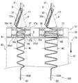
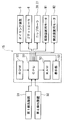
- FIG. 1 is an overall view of a toe band manufacturing apparatus. It is the figure which looked down at the rocking device and the conveyance device in the vertical direction. It is a functional block diagram of a toe band manufacturing apparatus.
- the left-right direction refers to a direction orthogonal to the conveyance direction of the toe band 103 in the horizontal plane.
- FIG. 1 is an overall view of a tow band manufacturing apparatus 1.
- a tow band manufacturing apparatus 1 includes a mixer 2, a filtration device 3, a spinning device 4, an oiling device 5, a godet roller 6, guide pins 7, 8, a hydrogenation device 9, a crimping device 10, and a swing device. 11, a guide device 12, a drying device 13, a packing device 14, and a control device 15.
- the tow band manufacturing apparatus 1 further includes a first detection device D1 provided on the upstream side in the conveyance direction of the water soaking device 9, and a second detection device D2 provided on the downstream side in the conveyance direction of the drying device 13. Yes.
- the toe band manufacturing apparatus 1 has at least a plurality of tow bands 103 conveying paths L from the water soaking apparatus 9 to the packing apparatus 14, and a plurality of types of tow bands having different FD and TD are conveyed in parallel to the respective conveying paths L. It is configured so that it can be manufactured.
- the mixer 2 has a mixing container 16 and a stirrer 17 and adjusts a spinning dope containing a material of the filament 100 (a material of cellulose acetate fiber in the present embodiment).
- the filtering device 3 filters the spinning dope supplied from the mixer 2 to remove impurities.
- the spinning device 4 includes a spinning cylinder 18, a spinneret 19, and a spinning pump (not shown), and spins a plurality of filaments 100.
- a plurality of the spinning cylinders 18 are arranged in parallel at intervals. In FIG. 1, only the structure of the single spinning cylinder 18 is illustrated.
- the spinneret 19 is provided on the upper part of each spinning cylinder 18.
- the spinning device 4 as an example, based on the dry spinning method, by driving a spinning pump, the spinning stock solution that has passed through the filtration device 3 is sent to each spinneret 19, and a plurality of spinning holes formed in each spinneret 19.
- the plurality of filaments 100 are spun by being discharged downward in the spinning cylinder 18.
- a plurality of filaments 100 are united while being conveyed from each spinning cylinder 18 to the downstream side in the conveying direction, whereby a yarn 101 is formed.
- a plurality of types of yarns 101 are formed by simultaneously spinning and uniting a plurality of filaments 100 having different FD and TD in a plurality of spinning cylinders 18.
- Oiling device 5 is disposed below each spinning cylinder 18 and attaches an oil emulsion to yarn 101.
- An oil emulsion contains water and a fiber oil agent as an example.
- the godet roller 6 is disposed below each oiling device 5 and is driven to rotate, thereby bringing the yarn 101 into contact with the circumferential surface and transporting it downstream in the transport direction.
- the guide pins 7 and 8 guide the yarn 101 downstream in the transport direction by contacting the yarn 101 on the downstream side in the transport direction of each godet roller 6.
- a plurality of yarns 101 are united while being conveyed toward the downstream side in the conveyance direction, whereby a yarn bundle 102 is formed.
- the yarn bundle 102 is conveyed to the water impregnation device 9.
- the water impregnation device 9 is provided in each conveyance path L, and attaches water to the yarn bundle 102, and plasticizes the yarn bundle 102 to facilitate crimping.
- a water-soluble organic solvent such as alcohol may be attached to the yarn bundle 102 in addition to water.
- the crimping device 10 is provided in each conveyance path L, and crimps the yarn bundles 102 that have passed through the hydrogenation device 9 individually.
- the crimping device 10 is a stuffing box type, and includes a pair of nip rollers (also referred to as a feed roller, a crimp roller, or a pressing roller) 20 and 21 and a stuffing box 22.
- the pair of nip rollers 20 and 21 are arranged so as to be pivotally supported in parallel and are driven to rotate, thereby inserting the yarn bundle 102 into the nip portion N between the pair of nip rollers 20 and 21.
- the stuffing box 22 includes a first plate member 23, a second plate member 24, and a third plate member 25, and is disposed on the downstream side in the transport direction of the pair of nip rollers 20 and 21.
- plate material 24 a mutual plate
- the third plate member 25 is disposed between the first plate member 23 and the second plate member 24 so as to extend from the first plate member 23 toward the second plate member 24. The end of the third plate member 25 on the downstream side in the conveying direction is biased in the direction of pressing the plate surface of the second plate member 24.
- plate material 25 are flat plate shape as an example, at least any of these may be curved plate shape.
- the oscillating device 11 is provided in each conveyance path L and causes the tow band 103 that has passed through the crimping device 10 to meander and convey in the left-right direction.
- the swing device 11 includes a base portion 30, a shaft portion 31, and a swing portion 32.
- the base unit 30 incorporates a swing device motor M1 and a cam mechanism 30a, and the rotational driving force of the swing device motor M1 is transmitted to the shaft portion 31 via the cam mechanism 30a.
- the shaft portion 31 extends in the vertical direction above the base portion 30.
- the cam mechanism 30a is an example of a swing mechanism, and the shaft portion 31 reciprocally rotates around the axis at a predetermined angle by the function of the cam mechanism 30a.
- the swing mechanism is not limited to the cam mechanism 30a, and may be a crank mechanism, for example.
- the oscillating portion 32 has a long shape extending in the transport direction, and has a concave flow passage 32a in which a cross section perpendicular to the longitudinal direction is recessed downward.
- the flow path 32a extends so as to have a downward slope toward the downstream side in the transport direction, and the tow band 103 is circulated.
- the flow passage 32a may extend horizontally in the transport direction.
- the end of the swinging portion 32 on the upstream side in the transport direction is fixed to the upper end of the shaft portion 31.
- FIG. 2 is a view of the swinging device 11 and the conveying device 40 looking down in the vertical direction.
- the oscillating portion 32 is rotated around the axis of the shaft portion 31 with the shaft center of the shaft portion 31 as the oscillating center Q by the oscillating device motor M1 and the cam mechanism 30a (see FIG. 1). Furthermore, it swings at a predetermined angle of swinging width on both sides in the transport direction within a horizontal plane. Accordingly, the tow band 103 that has passed through the flow passage 32a while being in contact with the swinging portion 32 is alternately swung in the right direction and the left direction and meanders.
- FIG. 1 is a view of the swinging device 11 and the conveying device 40 looking down in the vertical direction.
- each position of the straight line P passing through the center in the width direction of the swing part 32 when the swing part 32 swings with the maximum swing width is shown.
- the swinging devices 11 are provided at intervals in the left-right direction so as to correspond to the transport paths L. Thereby, a plurality of types of tow bands 103 are conveyed in a meandering state in parallel.
- the guide device 12 adjusts the vibration width of the meandering in the left-right direction of the toe band 103 while guiding the toe band 103 transported along each transport path L in the transport direction on the downstream side of the swing device 11 in the transport direction.
- the guide device 12 includes a stage portion 35 and a plurality of pairs of guide members 36 and 37.
- the stage unit 35 is a plate and is arranged so that the upper surface is horizontal.
- Each pair of guide members 36 and 37 is fixed to the upper surface of the stage portion 35 with a gap so as to sandwich each conveyance path of the toe band 103 extending in the conveyance direction in the left-right direction.
- tow bands 103 (tow bands 103A and 103B) that are transported along transport paths R1 and R2 while meandering in a gap between them are shown.
- the guide members 36 and 37 are formed using a plate material, and have fixed portions 36a and 37a and guide portions 36b and 37b.
- the fixing portions 36 a and 37 a are fixed to the upper surface of the stage portion 35 so as to be slidable in the left-right direction along the upper surface of the stage portion 35.
- a plurality of long holes 36a1, 37a1 extending in the left-right direction and penetrating in the thickness direction are formed in the fixing portions 36a, 37a.
- a pair of guide portions 36b and 37b are provided on both sides of the fixing portions 36a and 37a that extend in the vertical direction from the mutually opposite one ends in the horizontal direction and sandwich the toe band 103 conveyance direction in a horizontal plane.
- the guide portions 36b and 37b guide the toe band 103 in the transport direction while being in contact with the toe band 103.
- the operator inserts the bolt B into the long holes 36 a 1 and 37 a 1 and tightens the bolt B into the screw hole 35 a provided in the stage portion 35, whereby the guide members 36 and 37 are fixed to the stage portion 35.
- the position of the transport paths R1, R2 in the left-right direction can be adjusted by sliding each pair of guide members 36, 37 in the same direction in the left-right direction with the bolt B loosened. .
- the position in the left-right direction of the tow bands 103 ⁇ / b> A and 103 ⁇ / b> B when the tow band 103 is conveyed to the drying device 13 can be adjusted.
- the gap between the guide portions 36b and 37b can be adjusted by sliding the pair of guide members 36 and 37 in different directions in the left-right direction with the bolt B loosened.
- the torsional vibration widths W1 and W2 of the tow bands 103A and 103B when transported to the drying device 13 can be adjusted.
- the guide member 36 with respect to the stage unit 35, so that the downstream end of the flow path 32a of the swinging part 32 swings to the outside in the left-right direction of the transport paths R1, R2 in the horizontal plane.
- the fixing position of 37 may be adjusted. Accordingly, the tow bands 103A and 103B that have passed through the flow passage 32a can be efficiently brought into contact with the guide portions 36b and 37b, and the tow bands 103A and 103B can be conveyed while meandering with stable vibration widths W1 and W2.
- the method for adjusting the gap between the guide members 36 and 37 may be a method other than the above.
- the guide device 12 may be provided with a ball screw mechanism, and the gap between the guide members 36 and 37 may be adjusted by sliding and moving at least one of the guide members 36 and 37 in the left-right direction with the ball screw mechanism. Further, the guide device 12 may be omitted.
- the meandering vibration width of each toe band 103 can be individually adjusted. Increasing the swinging width of the swinging portion 32 can increase the vibration width of the meandering band of the toe band 103, and decreasing the swinging width of the swinging portion 32 can decrease the swinging width of the meandering of the toe band 103.
- the drying device 13 removes each part of water and volatile components contained in each tow band 103 by drying each tow band 103 that has passed through the guide device 12.
- a plurality of types of tow bands 103 are dried in parallel using a single drying device 13.
- the drying device 13 includes a transport device 40 for transporting a plurality of types of tow bands 103 in parallel.
- the conveying device 40 includes a driven roller 41, a driving roller 42, an endless belt 43, and a conveying device motor M2.
- the driven roller 41 and the driving roller 42 are disposed so as to be supported in parallel.
- the endless belt 43 is wound around the driven roller 41 and the driving roller 42 so as to be rotated in the transport direction.
- the conveyance device motor M ⁇ b> 2 is provided to transmit a rotational driving force to the driving roller 42.
- a plurality of types of tow bands 103 that have passed through the guide device 12 are arranged in parallel in the left-right direction while being meandered with a predetermined vibration width by the pair of guide members 36 and 37, respectively. It is placed on the upper surface of the belt 43 and conveyed (see FIG. 2).
- a gas here, heated air
- a plurality of types of tow bands 103 that have passed through the drying apparatus 13 have an appropriate amount corresponding to each. It is desirable to contain water.
- the tow band manufacturing apparatus 1 can adjust the residual amount of water contained in each tow band 103 that has passed through the drying apparatus 13 by adjusting the meandering vibration width of each tow band 103 in the guide apparatus 12. It is configured.
- the drying time of the tow bands 103A and 103B in the drying device 13 becomes longer, and the residual amount of water contained in the tow bands 103A and 103B can be reduced. Further, as the torsional width of the tow bands 103A and 103B is decreased, the drying time of the tow bands 103A and 103B in the drying device 13 is shortened, and the residual amount of water contained in the tow bands 103A and 103B can be increased. Such adjustment can be performed on at least one of the toe bands 103A and 103B.
- the packing device 14 packs the toe band 103.
- the packing device 14 includes a pair of rollers 44 and 45.
- the tow band 103 that has passed through the drying device 13 is inserted between the rollers 44 and 45, folded into a bale shape, and compressed, whereby the tow band 103 is packed into the packing container 26. Pack in.
- the first detection device D1 and the second detection device D2 are arranged at a predetermined position on the conveyance path in the toe band manufacturing device 1, and detect the amount of moisture contained in the yarn bundle 102 or the toe band 103 at the predetermined position.
- the first detection device D ⁇ b> 1 is disposed at a position corresponding to each conveyance path L of each yarn bundle 102 and detects the amount of moisture contained in the yarn bundle 102.
- the 2nd detection apparatus D2 is arrange
- the first detection device D1 and the second detection device D2 are infrared sensors as an example, but may be other sensors or a near-infrared spectrophotometer.
- FIG. 3 is a functional block diagram of the tow band manufacturing apparatus 1.
- the control device 15 includes a display unit 50, a CPU 51, a ROM 52, and a RAM 53.
- the display unit 50 is a liquid crystal display as an example, and is provided at a position where the operator of the housing of the control device 15 can visually recognize.
- the ROM 52 stores a control program for the tow band manufacturing apparatus 1.
- the RAM 53 stores various setting information set by the operator.
- the CPU 51 controls the driving of the oiling device 5, the godet roller 6, the pair of nip rollers 20, 21, the swing device motor M1, and the transport device motor M2 based on the control program and various setting information. Further, the CPU 51 displays the detection results of the first detection device D1 and the second detection device D2 on the display unit 50 based on the control program. Therefore, by confirming the detection result displayed on the display unit 50, the operator can determine the amount of moisture contained in the yarn bundle 102 at the position corresponding to the first detection device D1 and the position corresponding to the second detection device D2. The residual amount of water contained in the tow band 103 can be known.
- the control device 15 may be a personal computer (PC).
- each yarn bundle 102 to which water has been applied by the water applying apparatus 9 is crimped by the crimping apparatus 10, and a plurality of types of tow bands 103 are formed.
- a plurality of types of tow bands 103 are dried by a single drying device 13 while being meandered and conveyed along each conveyance path L. Thereby, the removal process which removes a part of water contained in each tow band 103 is performed.
- the remaining amount of water contained in each tow band 103 that has passed through the drying device 13 is detected by each second detection device D2, and the CPU 51 causes the display unit 50 to display each detection result. Thereby, the detection process of the residual amount of water of each tow band 103 is performed.
- the operator uses the guide device 12 to define a pair of guide members that define the transport path of the tow band 103.
- the positions of 36 and 37 with respect to the stage portion 35 are adjusted, and the vibration width of the meandering of the toe band 103 is adjusted.
- the adjustment process of adjusting the vibration width of the meandering of the tow band 103 so that the residual amount of water contained in any one of the plurality of types of tow bands 103 that have passed through the drying device 13 becomes the target value. Is done.
- the residual amount of water contained in each tow band 103 that has passed through the drying apparatus 13 is detected individually and accurately by each second detection device D2, and each detection result is displayed on the display unit 50. Is displayed. Therefore, the operator can individually and quickly check the residual amount of water contained in each tow band 103 that has passed through the drying device 13 based on each detection result displayed on the display unit 50.
- the operator adjusts the vibration width of the meandering of the tow band 103 in the guide device 12.
- the residual amount of water contained in the tow band 103 that has passed through the drying device 13 can be easily adjusted so as to be a target value.
- the target values of the residual amounts of water contained in the tow bands 103 are different from each other. It is generally difficult to properly dry the type of tow band 103.
- the meandering vibration width of each toe band 103 can be individually adjusted in the guide apparatus 12. Therefore, even when a plurality of types of tow bands 103 are dried in parallel using a single drying device 13, each tow band 103 is adjusted so that the residual amount of water contained in each tow band 103 becomes an appropriate amount. Can be properly dried.
- each toe band 103 is brought into contact with the swinging portions 32 of the plurality of swinging apparatuses 11, and each tow band 103 is meandered and transported to the transporting device 40. For this reason, in the drying apparatus 13, each tow band 103 can be efficiently dried from the upstream side in the transport direction.
- the tow bands 103 are arranged in parallel and are conveyed to the conveying device 40. For this reason, each toe band 103 can be efficiently dried in parallel while preventing the toe bands 103 from interfering with each other.
- the toe band manufacturing apparatus 1 a single drying apparatus 13 is used to dry each tow band 103. For this reason, while reducing the production cost of each toe band 103, the toe band manufacturing apparatus 1 can be comprised compactly.
- the tow band manufacturing apparatus 1 may include a plurality of drying apparatuses 13. In this case, a plurality of types of tow bands 103 can be dried in parallel by each drying device 13.
- the use of the tow band manufactured by the tow band manufacturing apparatus 1 is not limited to the use for manufacturing a cigarette filter, and for example, may be used for manufacturing absorbent bodies (also referred to as absorption members) such as paper diapers and sanitary products.
- the residual amount of water contained in each toe band is in accordance with each using a single drying device. It has an excellent effect that each tow band can be dried in parallel so as to be an appropriate amount. Therefore, it is beneficial to apply widely as a tow band manufacturing method and a tow band manufacturing apparatus capable of exhibiting the significance of this effect.
Landscapes
- Engineering & Computer Science (AREA)
- Textile Engineering (AREA)
- Chemical & Material Sciences (AREA)
- Materials Engineering (AREA)
- Treatment Of Fiber Materials (AREA)
- Yarns And Mechanical Finishing Of Yarns Or Ropes (AREA)
Abstract
トウバンドの製造方法は、水を添着された複数本のフィラメントが捲縮されてなる複数種類のトウバンドを、蛇行させて搬送しながら単一の乾燥装置で乾燥することにより、複数種類のトウバンドの各トウバンドに含まれる水の一部を除去する除去工程と、乾燥装置を通過した各トウバンドに含まれる水の残留量をそれぞれ検出する検出工程と、乾燥装置を通過した各トウバンドに含まれる水の残留量がそれぞれ目標値となるように、検出工程の検出結果に基づいて、各トウバンドの蛇行の振動幅を調整する調整工程と、を有する。
Description
本発明は、単一の乾燥装置を用いて複数種類のトウバンドを乾燥させるトウバンドの製造方法及びトウバンド製造装置に関する。
シガレットフィルターは、例えば、セルロースアセテート繊維等の複数本のフィラメントを用いたトウバンドにより製造される。トウバンド製造装置では、特許文献1に開示されるように、例えば、紡糸筒で紡糸した複数本のフィラメントがゴデットローラで合一されてヤーンが形成され、複数本のヤーンが更に合一されてヤーン束が形成される。ヤーン束は、水を添着して可塑化し易くされた後、捲縮装置に搬送される。捲縮装置では、例えば、一対のニップローラの間にヤーン束が挿通され、一対のニップローラの搬送方向下流側に設けられたスタッフィングボックスに押し込まれることで、ヤーン束が捲縮される。このようにして得られたトウバンドは、乾燥装置で乾燥されてベール状に折り畳まれ、梱包容器に梱包される。
フィルターロッド製造装置(「プラグ巻上機」とも称する。)では、特許文献2に開示されるように、例えば、梱包容器から繰り出されたトウバンドが開繊されて可塑剤を添着され、ロッド状に成形される。その後、トウバンドの外周に巻紙が巻回されてフィルターロッド(「プラグ」とも称する。)が製造される。このフィルターロッドを所定長さに切断することにより、シガレットフィルターが製造される。
例えば、FD(フィラメントデニール)またはTD(トータルデニール)のいずれかが異なる複数種類のトウバンドをトウバンド製造装置で並行して製造する場合、単一の乾燥装置で複数種類のトウバンドを並行して乾燥させる場合がある。複数種類のトウバンドは、フィルターロッド製造装置において複数本のフィラメント同士のもつれを防ぎながら適切に開繊されるようにするため、それぞれに応じた適量の水を含むことが望ましい。
そこで本発明は、複数種類のトウバンドを並行して製造する場合において、単一の乾燥装置を用いながら、各トウバンドに含まれる水の残留量がそれぞれに応じて適量になるように、各トウバンドを並行して乾燥可能にすることを目的とする。
本発明の一態様に係るトウバンドの製造方法は、水を添着された複数本のフィラメントが捲縮されてなる複数種類のトウバンドを、蛇行させて搬送しながら単一の乾燥装置で乾燥することにより、前記複数種類のトウバンドの各トウバンドに含まれる水の一部を除去する除去工程と、前記乾燥装置を通過した前記各トウバンドに含まれる水の残留量をそれぞれ検出する検出工程と、前記乾燥装置を通過した前記各トウバンドに含まれる水の残留量がそれぞれ目標値となるように、前記検出工程の検出結果に基づいて、前記各トウバンドの蛇行の振動幅を調整する調整工程と、を有する。
上記方法によれば、乾燥装置を通過した各トウバンドに含まれる水の残留量をそれぞれ検出し、この検出結果に基づいて、乾燥装置を通過した各トウバンドに含まれる水の残留量がそれぞれ目標値となるように、各トウバンドの蛇行の振動幅を調整する。従って、例えば、FDまたはTDのいずれかが異なる複数種類のトウバンドを、単一の乾燥装置を用いて並行して乾燥させる場合であっても、各トウバンドに含まれる水の残留量がそれぞれに応じて適量になるように、各トウバンドを適切に乾燥させることができる。
また、前記各トウバンドを搬送する前記乾燥装置の搬送装置よりも搬送方向上流側に設けられ、水平面内で搬送方向の両側に揺動する揺動部を有する揺動装置の前記揺動部に前記各トウバンドを接触させることにより、前記各トウバンドを蛇行させた状態で前記搬送装置に搬送させてもよい。
上記方法によれば、水平面内で搬送方向の両側に揺動する揺動部を有する揺動装置の前記揺動部に各トウバンドを接触させ、各トウバンドを蛇行させた状態で搬送装置に搬送させることにより、乾燥装置において、搬送方向上流側から各トウバンドを効率よく乾燥させることができる。
また、水平面内で搬送方向と直交する方向に間隔をおいて設けられた複数の前記揺動装置を用いて、前記各トウバンドを並列させて蛇行させた状態で前記搬送装置に搬送させてもよい。
上記方法によれば、水平面内で搬送方向と直交する方向に間隔をおいて設けられた複数の前記揺動装置を用いることにより、各トウバンドが互いに干渉するのを防止しながら、各トウバンドを並列させて蛇行させた状態で搬送装置に搬送させ、乾燥装置において、各トウバンドを並行して効率よく乾燥させることができる。
また、前記揺動装置の搬送方向下流側において、水平面内で前記各トウバンドの搬送方向の両側に設けられて前記各トウバンドをガイドする一対のガイド部材の間の間隙を調整することにより、前記各トウバンドの前記蛇行の振動幅を調整してもよい。
上記方法によれば、一対のガイド部材の間の間隙を調整することにより、各トウバンドの蛇行の振動幅を容易に調整できる。
また、前記検出工程は、前記各トウバンドに対応して設けられた複数の検出装置の検出結果に基づいて行ってもよい。
上記方法によれば、前記検出工程を、前記各トウバンドに対応して設けられた複数の検出装置の検出結果に基づいて行うことにより、各トウバンドに含まれる水の残留量を個別にかつ精度よく検出できる。
また、前記各トウバンドは、互いにフィラメントデニールまたはトータルデニールが異なっていてもよい。このような複数種類のトウバンドを製造する場合でも、各トウバンドを単一の乾燥装置を用いて適切に乾燥させることができる。
本発明の一態様に係るトウバンド製造装置は、水を添加された複数本のフィラメントが捲縮されてなる複数種類のトウバンドを、蛇行させて搬送しながら乾燥することにより、前記複数種類のトウバンドの各トウバンドに含まれる水の一部を除去する単一の乾燥装置と、前記乾燥装置を通過した前記各トウバンドに含まれる水の残留量をそれぞれ検出する検出装置と、を備え、前記乾燥装置を通過した前記各トウバンドに含まれる水の残留量がそれぞれ目標値となるように、前記検出装置の検出結果に基づいて、前記各トウバンドの蛇行の振動幅を調整可能に構成されている。
上記構成によれば、乾燥装置を通過した各トウバンドに含まれる水の残留量を検出装置でそれぞれ検出し、この検出装置の検出結果に基づいて、乾燥装置を通過した各トウバンドに含まれる水の残留量がそれぞれ目標値となるように、各トウバンドの蛇行の振動幅を調整する。従って、例えば、FDまたはTDのいずれかが異なる複数種類のトウバンドを、単一の乾燥装置を用いて並行して乾燥させる場合であっても、各トウバンドに含まれる水の残留量がそれぞれに応じて適量になるように、各トウバンドを適切に乾燥させることができる。
また、前記検出装置の検出結果を表示する表示部を更に備えていてもよい。この構成によれば、オペレータが表示部を確認することで、検出装置の検出結果を容易かつ迅速に知ることができる。
また、前記乾燥装置は、前記各トウバンドを搬送する搬送装置を有し、前記搬送装置よりも搬送方向上流側に設けられ、水平面内で搬送方向の両側に揺動する揺動部を有する揺動装置を更に備え、前記揺動部に前記各トウバンドが接触されることにより、前記各トウバンドが蛇行した状態で前記搬送装置に搬送されてもよい。
上記構成によれば、水平面内で搬送方向の両側に揺動する揺動部に各トウバンドを接触させ、各トウバンドを蛇行させた状態で搬送装置に搬送させることにより、乾燥装置において、搬送方向上流側から各トウバンドを効率よく乾燥させることができる。
また、複数の前記揺動装置が、水平面内で搬送方向と直交する方向に間隔をおいて設けられ、前記各トウバンドが並列して蛇行した状態で前記搬送装置に搬送されてもよい。
上記構成によれば、水平面内で搬送方向と直交する方向に間隔をおいて設けられた複数の揺動装置を用いることにより、各トウバンドを並列させて蛇行させた状態で搬送装置に搬送させ、乾燥装置において、各トウバンドを並行して効率よく乾燥させることができる。
また、前記揺動装置の搬送方向下流側において、水平面内で前記各トウバンドの搬送方向の両側に前記各トウバンドをガイドする一対のガイド部材が設けられ、前記一対のガイド部材の間の間隙を調整することにより、前記各トウバンドの前記蛇行の振動幅が調整されてもよい。
上記構成によれば、一対のガイド部材の間の間隙を調整することにより、各トウバンドの蛇行の振動幅を容易に調整できる。
また、複数の前記検出装置が、前記各トウバンドに対応して設けられていてもよい。この構成によれば、各トウバンドに対応して設けられた複数の検出装置により、各トウバンドに含まれる水の残留量を個別にかつ精度よく検出できる。
本発明によれば、複数種類のトウバンドを並行して製造する場合において、単一の乾燥装置を用いながら、各トウバンドに含まれる水の残留量がそれぞれに応じて適量になるように、各トウバンドを並行して乾燥できる。
本発明の実施形態について、各図を参照して説明する。以下の説明において、左右方向とは、トウバンド103の搬送方向と水平面内で直交する方向を指す。
[トウバンド製造装置]
図1は、トウバンド製造装置1の全体図である。図1に示すように、トウバンド製造装置1は、ミキサー2、濾過装置3、紡糸装置4、オイリング装置5、ゴデットローラ6、ガイドピン7、8、水添着装置9、捲縮装置10、揺動装置11、ガイド装置12、乾燥装置13、梱包装置14、及び、制御装置15を備えている。また、トウバンド製造装置1は、水添着装置9の搬送方向上流側に設けられた第1検出装置D1と、乾燥装置13の搬送方向下流側に設けられた第2検出装置D2とを更に備えている。トウバンド製造装置1は、少なくとも水添着装置9から梱包装置14に至る複数のトウバンド103の搬送経路Lを有し、FD及びTDの異なる複数種類のトウバンドを、各搬送経路Lに搬送しながら並行して製造できるように構成されている。
図1は、トウバンド製造装置1の全体図である。図1に示すように、トウバンド製造装置1は、ミキサー2、濾過装置3、紡糸装置4、オイリング装置5、ゴデットローラ6、ガイドピン7、8、水添着装置9、捲縮装置10、揺動装置11、ガイド装置12、乾燥装置13、梱包装置14、及び、制御装置15を備えている。また、トウバンド製造装置1は、水添着装置9の搬送方向上流側に設けられた第1検出装置D1と、乾燥装置13の搬送方向下流側に設けられた第2検出装置D2とを更に備えている。トウバンド製造装置1は、少なくとも水添着装置9から梱包装置14に至る複数のトウバンド103の搬送経路Lを有し、FD及びTDの異なる複数種類のトウバンドを、各搬送経路Lに搬送しながら並行して製造できるように構成されている。
ミキサー2は、混合容器16と攪拌機17とを有し、フィラメント100の材料(本実施形態ではセルロースアセテート繊維の材料)を含む紡糸原液を調整する。濾過装置3は、ミキサー2から供給される紡糸原液を濾過して不純物を除去する。
紡糸装置4は、紡糸筒18、紡糸口金19、及び、不図示の紡糸ポンプを有し、複数本のフィラメント100を紡糸する。紡糸筒18は、間隔をおいて複数並設されている。図1では、単一の紡糸筒18の構成のみを例示している。紡糸口金19は、各紡糸筒18の上部に設けられている。紡糸装置4では、一例として乾式紡糸法に基づき、紡糸ポンプを駆動することにより、濾過装置3を通過した紡糸原液が各紡糸口金19に送り込まれ、各紡糸口金19に形成された複数の紡糸孔から紡糸筒18の内部で下方に吐出されて複数本のフィラメント100が紡糸される。複数本のフィラメント100が、各紡糸筒18から搬送方向下流側に搬送されながら合一されることにより、ヤーン101が形成される。トウバンド製造装置1では、複数の紡糸筒18でFD及びTDの異なる複数本のフィラメント100が並行して紡糸され、かつ合一されることにより、複数種類のヤーン101が形成される。
オイリング装置5は、各紡糸筒18の下方に配置され、ヤーン101にオイルエマルジョンを付着させる。オイルエマルジョンには、一例として水及び繊維油剤が含まれる。ゴデットローラ6は、各オイリング装置5の下方に配置されて回転駆動されることにより、ヤーン101を周面に接触させて搬送方向下流側に搬送する。
ガイドピン7、8は、各ゴデットローラ6の搬送方向下流側において、ヤーン101と接触することにより、ヤーン101を搬送方向下流側に案内する。複数本のヤーン101が、搬送方向下流側に向けて搬送されながら合一されることにより、ヤーン束102が形成される。ヤーン束102は、水添着装置9に搬送される。水添着装置9は、各搬送経路Lに設けられ、ヤーン束102に水を添着し、ヤーン束102を可塑化して捲縮し易くする。なお、水添着装置9では、水に加えて、アルコール等の水溶性有機溶媒をヤーン束102に添着してもよい。
捲縮装置10は、各搬送経路Lに設けられ、水添着装置9を通過したヤーン束102を個別に捲縮する。捲縮装置10はスタッフィングボックス式であり、一対のニップローラ(フィードローラ、クリンプローラまたは押し込みローラとも称する。)20、21及びスタッフィングボックス22を有する。一対のニップローラ20、21は、平行に軸支されるように配置されて回転駆動されることにより、ヤーン束102を一対のニップローラ20、21間のニップ部Nに挿通させる。スタッフィングボックス22は、第1板材23、第2板材24及び第3板材25を有し、一対のニップローラ20、21の搬送方向下流側に配置される。第1板材23及び第2板材24は、互いの板面が対向配置される。第3板材25は、第1板材23及び第2板材24の間において、第1板材23から第2板材24に向けて延びるように配置される。第3板材25の搬送方向下流側の端部は、第2板材24の板面を押圧する方向に付勢されている。第1板材23、第2板材24及び第3板材25は、一例として平板状であるが、このうち少なくともいずれかが曲板状でもよい。
水添着装置9により水が添着されたヤーン束102は、一対のニップローラ20、21の間に挿通される際に、ニップ部Nにおいて微細な1次捲縮が掛けられ、その後、ニップ部Nから解放されてスタッフィングボックス22内に押し込まれる。図1に示すように、第3板材25の搬送方向下流側の端部が第2板材24の板面に押圧されることにより、スタッフィングボックス22の内部空間は、搬送方向下流側に向けて狭くなっている。ヤーン束102は、スタッフィングボックス22内で上下方向に蛇行して座屈しながら一時的に滞留した後、第2板材24と第3板材25との間を通過して搬送方向下流側に搬出される。これにより、高次捲縮が掛けられたトウバンド103が形成される。
揺動装置11は、各搬送経路Lに設けられ、捲縮装置10を通過したトウバンド103を左右方向に蛇行させて搬送させる。揺動装置11は、ベース部30、軸部31、及び、揺動部32を有する。ベース部30には、揺動装置用モータM1及びカム機構30aが内蔵され、揺動装置用モータM1の回転駆動力が、カム機構30aを介して軸部31に伝達される。軸部31は、ベース部30の上方に垂直方向に延びている。カム機構30aは、揺動機構の一例であり、軸部31はカム機構30aの働きにより、その軸周りに所定角度で往復回転する。なお、揺動機構はカム機構30aに限定されず、例えば、クランク機構でもよい。揺動部32は、搬送方向に延びる長尺状であり、長手方向と直交する断面が下方に窪んだ凹状の流通路32aを有する。流通路32aは、搬送方向下流側に向かって下り勾配となるように傾斜して延び、トウバンド103が流通される。なお、流通路32aは、搬送方向に水平に延びていてもよい。揺動部32の搬送方向上流側の端部は、軸部31の上端部に固定されている。
図2は、揺動装置11と搬送装置40とを鉛直方向に見下ろした図である。トウバンド製造装置1の稼働時には、揺動部32は、揺動装置用モータM1及びカム機構30a(図1参照)により、軸部31の軸心を揺動中心Qとして、軸部31の軸周りに、水平面内で搬送方向の両側に所定角度の振り幅で揺動する。これにより、揺動部32と接触しながら流通路32aを通過したトウバンド103が、右方向及び左方向に交互に振られて蛇行される。図2では、揺動部32が最大の振り幅で揺動した際の揺動部32の幅方向中央を通る直線Pの各位置を示している。トウバンド製造装置1では、各揺動装置11が各搬送経路Lに対応するように、左右方向に間隔をおいて設けられている。これにより、複数種類のトウバンド103が並列されて蛇行した状態で搬送される。
ガイド装置12は、揺動装置11の搬送方向下流側において、各搬送経路Lを搬送されるトウバンド103を搬送方向にガイドしながら、トウバンド103の左右方向における蛇行の振動幅を調整する。ガイド装置12は、ステージ部35と、複数対のガイド部材36、37とを有する。ステージ部35は板体であり、上面が水平になるように配置されている。各対のガイド部材36、37は、搬送方向に延びるトウバンド103の各搬送路を左右方向に挟むように、間隙をおいてステージ部35の上面に固定されている。図2では、一例として、隣接する搬送路R1、R2を左右方向にそれぞれ挟むように、ステージ部35の上面に固定された二対のガイド部材36、37と、二対のガイド部材36、37の間の間隙で蛇行されながら搬送路R1、R2を搬送される2種類のトウバンド103(トウバンド103A、103B)とを示している。
ガイド部材36、37は、板材を用いて形成され、固定部36a、37aと、ガイド部36b、37bとを有する。固定部36a、37aは、ステージ部35の上面に沿って左右方向にスライド移動可能に、ステージ部35の上面に固定される。固定部36a、37aには、左右方向に延びかつ厚み方向に貫通する複数の長孔36a1、37a1が形成されている。ガイド部36b、37bは、固定部36a、37aの互いに対向する左右方向一端部から垂直方向に延び、水平面内でトウバンド103の搬送方向を挟む両側に一対設けられる。これによりガイド部36b、37bは、トウバンド103と接触しながら、トウバンド103を搬送方向にガイドする。オペレータが、長孔36a1、37a1にボルトBを挿通させ、ステージ部35に設けられたねじ孔35aにボルトBを締め込むことにより、ガイド部材36、37がステージ部35に固定される。ここで図2に示す例では、ボルトBを緩めた状態で、左右方向で同一方向に各対のガイド部材36、37をスライドさせることにより、搬送路R1、R2の左右方向における位置を調整できる。これにより、トウバンド103を乾燥装置13に搬送する際のトウバンド103A、103Bの左右方向における位置を調整できる。またボルトBを緩めた状態で、左右方向で異なる方向に各対のガイド部材36、37をスライドさせることにより、ガイド部36b、37bの間の間隙を調整できる。これにより、乾燥装置13に搬送する際のトウバンド103A、103Bの蛇行の振動幅W1、W2を調整できる。
なお一例として、揺動部32の流通路32aの搬送方向下流側の端部が、水平面内で搬送路R1、R2の左右方向における外側まで揺動するように、ステージ部35に対するガイド部材36、37の固定位置を調整してもよい。これにより、流通路32aを通過したトウバンド103A、103Bをガイド部36b、37bに効率よく接触させて、トウバンド103A、103Bを安定した振動幅W1、W2で蛇行させながら搬送できる。
ガイド部材36、37の間隙を調整する方法は、上記以外の方法でもよい。例えば、ガイド装置12にボールねじ機構を設け、ガイド部材36、37の少なくとも一方を前記ボールねじ機構により左右方向にスライド移動させることで、ガイド部材36、37の間隙を調整してもよい。また、ガイド装置12は省略してもよい。この場合、揺動装置11における揺動部32の振り幅を個別に調整することで、各トウバンド103の蛇行の振動幅を個別に調整できる。揺動部32の振り幅を大きくすれば、トウバンド103の蛇行の振動幅を増大でき、揺動部32の振り幅を小さくすれば、トウバンド103の蛇行の振動幅を減少できる。
乾燥装置13は、ガイド装置12を通過した各トウバンド103を乾燥することにより、各トウバンド103に含まれる水及び揮発成分の各一部を除去する。トウバンド製造装置1では、単一の乾燥装置13を用いて、複数種類のトウバンド103を並行して乾燥させる。図1に示すように、乾燥装置13は、複数種類のトウバンド103を並行して搬送するための搬送装置40を有する。搬送装置40は、従動ローラ41、駆動ローラ42、無端ベルト43、及び、搬送装置用モータM2を有する。従動ローラ41及び駆動ローラ42は、平行に軸支されるように配置されている。無端ベルト43は、搬送方向に回動されるように、従動ローラ41及び駆動ローラ42に巻回されている。搬送装置用モータM2は、駆動ローラ42に回転駆動力を伝達するように設けられている。搬送装置用モータM2を駆動させると、ガイド装置12を通過した複数種類のトウバンド103が、各対のガイド部材36、37によりそれぞれ所定の振動幅で蛇行された状態で左右方向に並列され、無端ベルト43の上面に載置されて搬送される(図2参照)。乾燥装置13の内部において、複数種類のトウバンド103に気体(ここでは加熱空気)を当てることにより、各トウバンド103に含まれる水及び揮発成分の各一部が除去される。
ここで、フィルターロッド製造装置において複数本のフィラメント同士のもつれを防ぎながらトウバンド103を適切に開繊する等の目的により、乾燥装置13を通過した複数種類のトウバンド103は、それぞれに応じた適量の水を含有していることが望ましい。これに対してトウバンド製造装置1は、ガイド装置12において各トウバンド103の蛇行の振動幅をそれぞれ調整することにより、乾燥装置13を通過した各トウバンド103に含まれる水の残留量をそれぞれ調整可能に構成されている。
図2に示すように、一例として、ガイド装置12において二対のガイド部材36、37の間の間隙をそれぞれ調整すれば、無端ベルト43上を搬送されるトウバンド103A、103Bの蛇行の振動幅W1、W2を調整できる。これにより、乾燥装置13におけるトウバンド103A、103Bの乾燥時間を変更でき、トウバンド103A、103Bに含まれる水の残留量を調整できる。トウバンド103A、103Bの蛇行の振動幅を増大させるほど、乾燥装置13におけるトウバンド103A、103Bの乾燥時間が長くなり、トウバンド103A、103Bに含まれる水の残留量を減少できる。また、トウバンド103A、103Bの蛇行の振動幅を減少させるほど、乾燥装置13におけるトウバンド103A、103Bの乾燥時間が短くなり、トウバンド103A、103Bに含まれる水の残留量を増大できる。このような調整は、トウバンド103A、103Bの少なくとも一方に行うことができる。
図1に示すように、梱包装置14は、トウバンド103を梱包する。梱包装置14は、一対のローラ44、45を有し、乾燥装置13を通過したトウバンド103をローラ44、45の間に挿通させ、ベール状に折り畳んで圧縮することにより、トウバンド103を梱包容器26に梱包する。
第1検出装置D1及び第2検出装置D2は、トウバンド製造装置1における搬送経路の所定位置に配置され、所定位置のヤーン束102またはトウバンド103に含まれる水分量を検出する。具体的に、第1検出装置D1は、各ヤーン束102の各搬送経路Lに対応する位置にそれぞれ配置され、ヤーン束102に含まれる水分量を検出する。また、第2検出装置D2は、乾燥装置13を通過した複数種類のトウバンド103のそれぞれに対応する位置に配置され、各トウバンド103に含まれる水の残留量を検出する(図2参照)。第1検出装置D1及び第2検出装置D2は、一例として赤外線センサであるが、その他のセンサでもよいし、近赤外線分光光度計でもよい。
制御装置15は、トウバンド製造装置1の各部の動作を制御し、また、第1検出装置D1及び第2検出装置D2の各検出結果を表示部50に表示する。図3は、トウバンド製造装置1の機能ブロック図である。図3に示すように、制御装置15は、表示部50、CPU51、ROM52、及び、RAM53を有する。表示部50は、一例として液晶ディスプレイであり、制御装置15の筐体のオペレータが視認可能な位置に設けられる。ROM52には、トウバンド製造装置1の制御プログラムが格納されている。RAM53には、オペレータが設定した各種設定情報が格納されている。CPU51は、制御プログラム及び各種設定情報に基づき、オイリング装置5、ゴデットローラ6、一対のニップローラ20、21、揺動装置用モータM1、及び、搬送装置用モータM2の各々の駆動を制御する。またCPU51は、制御プログラムに基づき、第1検出装置D1及び第2検出装置D2の検出結果を表示部50に表示する。従って、表示部50に表示された検出結果を確認することで、オペレータは、第1検出装置D1に対応する位置のヤーン束102に含まれる水分量と、第2検出装置D2に対応する位置のトウバンド103に含まれる水の残留量とを知ることができる。なお、制御装置15は、パーソナルコンピュータ(PC)でもよい。
トウバンド製造装置1の稼働時には、水添着装置9で水を添着された各ヤーン束102が捲縮装置10で捲縮され、複数種類のトウバンド103が形成される。複数種類のトウバンド103は、各搬送経路Lを蛇行して搬送されながら単一の乾燥装置13で乾燥される。これにより、各トウバンド103に含まれる水の一部を除去する除去工程が行われる。乾燥装置13を通過した各トウバンド103に含まれる水の残留量が、各第2検出装置D2により検出され、CPU51が、この各検出結果を表示部50に表示させる。これにより、各トウバンド103の水の残留量の検出工程が行われる。いずれかのトウバンド103に含まれる水の残留量が、その目標値とずれていることをオペレータが確認した場合、オペレータは、ガイド装置12において、このトウバンド103の搬送路を規定する一対のガイド部材36、37のステージ部35に対する位置を調整し、トウバンド103の蛇行の振動幅を調整する。これにより、乾燥装置13を通過した複数種類のトウバンド103のうちのいずれかのトウバンド103に含まれる水の残留量が目標値となるように、当該トウバンド103の蛇行の振動幅を調整する調整工程が行われる。
このようにトウバンド製造装置1では、乾燥装置13を通過した各トウバンド103に含まれる水の残留量が、各第2検出装置D2で個別にかつ精度よく検出され、この各検出結果が表示部50に表示される。従ってオペレータは、表示部50に表示された各検出結果に基づいて、乾燥装置13を通過した各トウバンド103に含まれる水の残留量を個別にかつ迅速にチェックできる。また、乾燥装置13を通過したいずれかのトウバンド103に含まれる水の残留量が目標値とずれている場合、オペレータは、ガイド装置12において、当該トウバンド103の蛇行の振動幅を調整することで、乾燥装置13を通過した当該トウバンド103に含まれる水の残留量が目標値となるように、容易に調整できる。
ここで、例えばFDまたはTDのいずれかが異なる複数種類のトウバンド103を乾燥させる場合、各トウバンド103に含まれる水の残留量の目標値が互いに異なるため、単一の乾燥装置で並行して複数種類のトウバンド103を適切に乾燥することは一般に困難である。これに対してトウバンド製造装置1では、ガイド装置12において、各トウバンド103の蛇行の振動幅を個別に調整できる。よって、複数種類のトウバンド103を単一の乾燥装置13を用いて並行して乾燥させる場合でも、各トウバンド103に含まれる水の残留量がそれぞれに応じて適量になるように、各トウバンド103を適切に乾燥させることができる。
また、トウバンド製造装置1では、複数の揺動装置11の揺動部32に各トウバンド103を接触させ、各トウバンド103を蛇行させた状態で搬送装置40に搬送させる。このため乾燥装置13において、各トウバンド103を搬送方向上流側から効率よく乾燥させることができる。
また、左右方向に間隔をおいて設けられた複数の揺動装置11を用いて、各トウバンド103を並列させて蛇行させた状態で搬送装置40に搬送させる。このため、各トウバンド103が互いに干渉するのを防止しながら、各トウバンド103を並行して効率よく乾燥させることができる。
また、トウバンド製造装置1では、各トウバンド103を乾燥させるために単一の乾燥装置13を用いる。このため、各トウバンド103の生産コストの低減が図れるとともに、トウバンド製造装置1をコンパクトに構成することができる。
なお、トウバンド製造装置1は、複数の乾燥装置13を備えてもよい。この場合、各乾燥装置13で複数種類のトウバンド103を並行して乾燥させることができる。また、トウバンド製造装置1で製造するトウバンドの用途は、シガレットフィルターの製造用途に限定されず、例えば、紙オムツや生理用品等の吸収体(吸収部材とも称する。)の製造用途でもよい。
以上のように、本発明の一態様によれば、複数種類のトウバンドを並行して製造する場合において、単一の乾燥装置を用いながら、各トウバンドに含まれる水の残留量がそれぞれに応じて適量になるように、各トウバンドを並行して乾燥できる優れた効果を有する。従って、この効果の意義を発揮できるトウバンドの製造方法及びトウバンド製造装置として広く適用すると有益である。
D1 第1検出装置
D2 第2検出装置
1 トウバンド製造装置
11 揺動装置
13 乾燥装置
32 揺動部
36、37 ガイド部材
40 搬送装置
50 表示部
100 フィラメント
103、103A、103B トウバンド
D2 第2検出装置
1 トウバンド製造装置
11 揺動装置
13 乾燥装置
32 揺動部
36、37 ガイド部材
40 搬送装置
50 表示部
100 フィラメント
103、103A、103B トウバンド
Claims (12)
- 水を添着された複数本のフィラメントが捲縮されてなる複数種類のトウバンドを、蛇行させて搬送しながら単一の乾燥装置で乾燥することにより、前記複数種類のトウバンドの各トウバンドに含まれる水の一部を除去する除去工程と、
前記乾燥装置を通過した前記各トウバンドに含まれる水の残留量をそれぞれ検出する検出工程と、
前記乾燥装置を通過した前記各トウバンドに含まれる水の残留量がそれぞれ目標値となるように、前記検出工程の検出結果に基づいて、前記各トウバンドの蛇行の振動幅を調整する調整工程と、を有する、トウバンドの製造方法。 - 前記各トウバンドを搬送する前記乾燥装置の搬送装置よりも搬送方向上流側に設けられ、水平面内で搬送方向の両側に揺動する揺動部を有する揺動装置の前記揺動部に前記各トウバンドを接触させることにより、前記各トウバンドを蛇行させた状態で前記搬送装置に搬送させる、請求項1に記載のトウバンドの製造方法。
- 水平面内で搬送方向と直交する方向に間隔をおいて設けられた複数の前記揺動装置を用いて、前記各トウバンドを並列させて蛇行させた状態で前記搬送装置に搬送させる、請求項2に記載のトウバンドの製造方法。
- 前記揺動装置の搬送方向下流側において、水平面内で前記各トウバンドの搬送方向の両側に設けられて前記各トウバンドをガイドする一対のガイド部材の間の間隙を調整することにより、前記各トウバンドの前記蛇行の振動幅を調整する、請求項2または3に記載のトウバンドの製造方法。
- 前記検出工程は、前記各トウバンドに対応して設けられた複数の検出装置の検出結果に基づいて行う、請求項1~4のいずれか1項に記載のトウバンドの製造方法。
- 前記各トウバンドは、互いにフィラメントデニールまたはトータルデニールが異なる、請求項1~5のいずれか1項に記載のトウバンドの製造方法。
- 水を添加された複数本のフィラメントが捲縮されてなる複数種類のトウバンドを、蛇行させて搬送しながら乾燥することにより、前記複数種類のトウバンドの各トウバンドに含まれる水の一部を除去する単一の乾燥装置と、
前記乾燥装置を通過した前記各トウバンドに含まれる水の残留量をそれぞれ検出する検出装置と、を備え、
前記乾燥装置を通過した前記各トウバンドに含まれる水の残留量がそれぞれ目標値となるように、前記検出装置の検出結果に基づいて、前記各トウバンドの蛇行の振動幅を調整可能に構成されている、トウバンド製造装置。 - 前記検出装置の検出結果を表示する表示部を更に備える、請求項7に記載のトウバンド製造装置。
- 前記乾燥装置は、前記各トウバンドを搬送する搬送装置を有し、
前記搬送装置よりも搬送方向上流側に設けられ、水平面内で搬送方向の両側に揺動する揺動部を有する揺動装置を更に備え、
前記揺動部に前記各トウバンドが接触されることにより、前記各トウバンドが蛇行した状態で前記搬送装置に搬送される、請求項7または8に記載のトウバンド製造装置。 - 複数の前記揺動装置が、水平面内で搬送方向と直交する方向に間隔をおいて設けられ、前記各トウバンドが並列して蛇行した状態で前記搬送装置に搬送される、請求項9に記載のトウバンド製造装置。
- 前記揺動装置の搬送方向下流側において、水平面内で前記各トウバンドの搬送方向の両側に前記各トウバンドをガイドする一対のガイド部材が設けられ、
前記一対のガイド部材の間の間隙を調整することにより、前記各トウバンドの前記蛇行の振動幅が調整される、請求項9または10に記載のトウバンド製造装置。 - 複数の前記検出装置が、前記各トウバンドに対応して設けられている、請求項7~11のいずれか1項に記載のトウバンド製造装置。
Priority Applications (3)
| Application Number | Priority Date | Filing Date | Title |
|---|---|---|---|
| PCT/JP2015/003880 WO2017021995A1 (ja) | 2015-07-31 | 2015-07-31 | トウバンドの製造方法及びトウバンド製造装置 |
| JP2017532236A JP6243582B2 (ja) | 2015-07-31 | 2015-07-31 | トウバンドの製造方法及びトウバンド製造装置 |
| CN201580082123.7A CN107849771B (zh) | 2015-07-31 | 2015-07-31 | 丝束带的制造方法及丝束带制造装置 |
Applications Claiming Priority (1)
| Application Number | Priority Date | Filing Date | Title |
|---|---|---|---|
| PCT/JP2015/003880 WO2017021995A1 (ja) | 2015-07-31 | 2015-07-31 | トウバンドの製造方法及びトウバンド製造装置 |
Publications (1)
| Publication Number | Publication Date |
|---|---|
| WO2017021995A1 true WO2017021995A1 (ja) | 2017-02-09 |
Family
ID=57944046
Family Applications (1)
| Application Number | Title | Priority Date | Filing Date |
|---|---|---|---|
| PCT/JP2015/003880 Ceased WO2017021995A1 (ja) | 2015-07-31 | 2015-07-31 | トウバンドの製造方法及びトウバンド製造装置 |
Country Status (3)
| Country | Link |
|---|---|
| JP (1) | JP6243582B2 (ja) |
| CN (1) | CN107849771B (ja) |
| WO (1) | WO2017021995A1 (ja) |
Cited By (1)
| Publication number | Priority date | Publication date | Assignee | Title |
|---|---|---|---|---|
| JP2023509013A (ja) * | 2019-12-30 | 2023-03-06 | フィリップ・モーリス・プロダクツ・ソシエテ・アノニム | シートを捲縮するための方法および装置 |
Citations (2)
| Publication number | Priority date | Publication date | Assignee | Title |
|---|---|---|---|---|
| JP2004191038A (ja) * | 2002-11-29 | 2004-07-08 | Mitsubishi Rayon Co Ltd | アセテートトウの水分制御装置および水分制御方法 |
| JP2008504457A (ja) * | 2004-06-25 | 2008-02-14 | セラニーズ・アセテート・リミテッド・ライアビリティ・カンパニー | 酢酸セルローストウおよびその製造方法 |
Family Cites Families (3)
| Publication number | Priority date | Publication date | Assignee | Title |
|---|---|---|---|---|
| CN201417067Y (zh) * | 2009-06-10 | 2010-03-03 | 东莞德永佳纺织制衣有限公司 | 一种网带式烘干机 |
| CN201621933U (zh) * | 2010-02-09 | 2010-11-03 | 常州市范群干燥设备有限公司 | 一种网带式干燥机 |
| CN102948924A (zh) * | 2011-08-18 | 2013-03-06 | 成都宏亿实业集团有限公司 | 烟用复合丝束滤嘴棒 |
-
2015
- 2015-07-31 JP JP2017532236A patent/JP6243582B2/ja active Active
- 2015-07-31 CN CN201580082123.7A patent/CN107849771B/zh active Active
- 2015-07-31 WO PCT/JP2015/003880 patent/WO2017021995A1/ja not_active Ceased
Patent Citations (2)
| Publication number | Priority date | Publication date | Assignee | Title |
|---|---|---|---|---|
| JP2004191038A (ja) * | 2002-11-29 | 2004-07-08 | Mitsubishi Rayon Co Ltd | アセテートトウの水分制御装置および水分制御方法 |
| JP2008504457A (ja) * | 2004-06-25 | 2008-02-14 | セラニーズ・アセテート・リミテッド・ライアビリティ・カンパニー | 酢酸セルローストウおよびその製造方法 |
Cited By (2)
| Publication number | Priority date | Publication date | Assignee | Title |
|---|---|---|---|---|
| JP2023509013A (ja) * | 2019-12-30 | 2023-03-06 | フィリップ・モーリス・プロダクツ・ソシエテ・アノニム | シートを捲縮するための方法および装置 |
| JP7675728B2 (ja) | 2019-12-30 | 2025-05-13 | フィリップ・モーリス・プロダクツ・ソシエテ・アノニム | シートを捲縮するための方法および装置 |
Also Published As
| Publication number | Publication date |
|---|---|
| JP6243582B2 (ja) | 2017-12-06 |
| JPWO2017021995A1 (ja) | 2018-01-11 |
| CN107849771B (zh) | 2020-03-13 |
| CN107849771A (zh) | 2018-03-27 |
Similar Documents
| Publication | Publication Date | Title |
|---|---|---|
| EP2893820B1 (en) | Method for producing filter cigarette, filter, and filter cigarette | |
| KR102074656B1 (ko) | 시거렛 필터용 셀룰로오스아세테이트 섬유의 토우 밴드, 시거렛 필터, 토우 밴드의 제조 장치, 및 토우 밴드의 제조 방법 | |
| NO132712B (ja) | ||
| CN107849750B (zh) | 丝束带的制造方法、丝束带制造装置以及香烟过滤嘴的制造方法 | |
| US20230180822A1 (en) | Tow band for heated tobacco product tip, tip for heated tobacco product, method for manufacturing tow band for heated tobacco product tip, and method for manufacturing heated tobacco product tip | |
| JPWO2016084120A1 (ja) | トウバンドの捲縮検査方法、トウバンドの製造方法、トウバンド捲縮検査装置、及びトウバンド製造装置 | |
| JP6243582B2 (ja) | トウバンドの製造方法及びトウバンド製造装置 | |
| JP6018353B1 (ja) | シガレットフィルター製造装置、シガレットフィルター製造装置用制御装置、シガレットフィルター製造装置用演算装置、及びシガレットフィルター製造装置の制御方法 | |
| JP6873634B2 (ja) | シガレットフィルター製造装置及びシガレットフィルター製造装置の制御方法 | |
| WO2006054742A1 (ja) | トウバンドの製造方法及びトウバンドの製造装置 | |
| JP6359117B2 (ja) | トウバンドの製造方法及びトウバンド製造装置 | |
| WO2012017850A1 (ja) | フィルタ製造装置、フィルタ製造方法、およびフィルタ | |
| EP3178332A1 (en) | Filter manufacturing machine | |
| ITBO20090551A1 (it) | Metodo e macchina per la produzione contemporanea di almeno due bachi di filtro per sigarette. | |
| CN107734980A (zh) | 用于处理刚性包装纸幅材料的改进的滤嘴条成型机 | |
| JP2018521660A5 (ja) | ||
| JP7312650B2 (ja) | トウ開繊繊維集合体の製造方法 | |
| CN101120817B (zh) | 卷烟滤嘴的生产机器 | |
| BR112019017718B1 (pt) | Aparelho e método para formar colunas de filtro | |
| JP7312649B2 (ja) | トウ開繊繊維集合体の製造方法 | |
| CN117120677A (zh) | 短纤维的制造方法、无纺布的制造方法、短纤维制造装置以及无纺布制造装置 | |
| JP2026505184A (ja) | エアロゾル発生物品構成要素用のエアロゾル発生基体のシートを脆弱化するための装置及び方法 | |
| CN115074886A (zh) | 丝束开纤体制造装置及丝束开纤体的制造方法 | |
| TWI468120B (zh) | 濾嘴香煙製造方法以及濾嘴與濾嘴香煙 | |
| JPH10215842A (ja) | フィルタシガレットの製造機及びその製造方法 |
Legal Events
| Date | Code | Title | Description |
|---|---|---|---|
| 121 | Ep: the epo has been informed by wipo that ep was designated in this application |
Ref document number: 15900309 Country of ref document: EP Kind code of ref document: A1 |
|
| ENP | Entry into the national phase |
Ref document number: 2017532236 Country of ref document: JP Kind code of ref document: A |
|
| NENP | Non-entry into the national phase |
Ref country code: DE |
|
| 122 | Ep: pct application non-entry in european phase |
Ref document number: 15900309 Country of ref document: EP Kind code of ref document: A1 |