WO2017018296A1 - 導風ユニットおよび冷却モジュール - Google Patents
導風ユニットおよび冷却モジュール Download PDFInfo
- Publication number
- WO2017018296A1 WO2017018296A1 PCT/JP2016/071286 JP2016071286W WO2017018296A1 WO 2017018296 A1 WO2017018296 A1 WO 2017018296A1 JP 2016071286 W JP2016071286 W JP 2016071286W WO 2017018296 A1 WO2017018296 A1 WO 2017018296A1
- Authority
- WO
- WIPO (PCT)
- Prior art keywords
- connection portion
- duct
- air
- engine
- shroud
- Prior art date
- Legal status (The legal status is an assumption and is not a legal conclusion. Google has not performed a legal analysis and makes no representation as to the accuracy of the status listed.)
- Ceased
Links
Images










Classifications
-
- B—PERFORMING OPERATIONS; TRANSPORTING
- B60—VEHICLES IN GENERAL
- B60K—ARRANGEMENT OR MOUNTING OF PROPULSION UNITS OR OF TRANSMISSIONS IN VEHICLES; ARRANGEMENT OR MOUNTING OF PLURAL DIVERSE PRIME-MOVERS IN VEHICLES; AUXILIARY DRIVES FOR VEHICLES; INSTRUMENTATION OR DASHBOARDS FOR VEHICLES; ARRANGEMENTS IN CONNECTION WITH COOLING, AIR INTAKE, GAS EXHAUST OR FUEL SUPPLY OF PROPULSION UNITS IN VEHICLES
- B60K11/00—Arrangement in connection with cooling of propulsion units
- B60K11/02—Arrangement in connection with cooling of propulsion units with liquid cooling
- B60K11/04—Arrangement or mounting of radiators, radiator shutters, or radiator blinds
-
- F—MECHANICAL ENGINEERING; LIGHTING; HEATING; WEAPONS; BLASTING
- F01—MACHINES OR ENGINES IN GENERAL; ENGINE PLANTS IN GENERAL; STEAM ENGINES
- F01P—COOLING OF MACHINES OR ENGINES IN GENERAL; COOLING OF INTERNAL-COMBUSTION ENGINES
- F01P11/00—Component parts, details, or accessories not provided for in, or of interest apart from, groups F01P1/00 - F01P9/00
- F01P11/10—Guiding or ducting cooling-air, to, or from, liquid-to-air heat exchangers
Definitions
- the present disclosure relates to an air guide unit and a cooling module provided in an engine room of an automobile.
- a duct for cooling an intercooler for a vehicle described in Patent Document 1 is known as one of the air guiding units such as the above-described air guiding unit.
- the intercooler cooling duct is a duct that connects an air outlet formed on the engine room side of the engine hood of the vehicle and an air inlet of the intercooler.
- the intercooler cooling duct of Patent Document 1 includes an upper end opening connected to an air outlet of the engine hood and a lower end opening that is abutted against the air intake of the intercooler when the engine hood is closed. And.
- the intercooler cooling duct supplies outside air that has passed through the engine hood and exited from the air outlet to the intercooler.
- an engine room of an automobile is provided with a cooling module that performs a cooling function, in other words, a cooling module.
- the cooling module is composed of a radiator that radiates engine cooling water, a condenser that is a radiator of an air conditioner that air-conditions the vehicle interior, a blower that generates cooling air, and a shroud that fixes them and guides the cooling air Has been.
- the heat of the refrigerant circulating in the air conditioner and the heat of the engine cooling water are dissipated by the running wind and the cooling air from the blower.
- the cooling module is usually placed in front of the engine room. Therefore, the heat discarded by the cooling module, that is, the heat transferred to the outside air by the radiator and the condenser flows to the traveling engine disposed at the rear of the vehicle with respect to the cooling module, which causes a reduction in heat radiation efficiency. .
- the inventors considered providing a duct that guides the front wind flowing into the engine room from the front of the vehicle to the space behind the engine.
- a duct is simply provided in such a manner, it has been considered that a new situation of worsening serviceability related to a traveling engine such as replacement of an engine plug occurs.
- the present disclosure provides an air guide unit and a cooling module capable of cooling a space behind the vehicle with respect to the traveling engine in the engine room while suppressing deterioration in serviceability related to the traveling engine.
- the purpose is to do.
- an air guide unit of the present disclosure includes: A wind guide unit applied to an automobile in which air flows into an engine room from an engine room opening that is opened in front of a vehicle in an engine room where a traveling engine is disposed, The air conditioner radiator and the engine cooling heat exchanger for cooling the traveling engine and the blower are fixed, and the air passing through the radiator and the engine cooling heat exchanger is guided through the engine room opening, A shroud with a vent hole, A first opening that is connected to the shroud at the ventilation hole and opens through the ventilation hole, and a second opening that opens to the rear of the vehicle with respect to the traveling engine in the engine room, the first opening and the second opening.
- the air duct that allows air to flow between The air duct includes a first duct member that constitutes at least a part of the air duct and has a second opening and forms a first duct passage through which air from the ventilation hole flows to the second opening.
- the first duct member has a first connection portion configured to be able to remove the first duct member from the shroud on the side opposite to the second opening side.
- the air guide duct is connected to the shroud through the shroud vent hole and opens through the vent hole, and the second opening that opens to the rear of the vehicle with respect to the traveling engine in the engine room. Part.
- the air guide duct allows air to flow between the first opening and the second opening. Therefore, it is possible to cool the space behind the vehicle with respect to the traveling engine in the engine room by the air guided to the air guide duct.
- the air duct includes a first duct member, and the first duct member has a first connecting portion configured to be able to remove the first duct member from the shroud, on the side opposite to the second opening side.
- the first duct member can be separated from the shroud and removed from the engine room without removing the shroud from the engine room. Therefore, it is possible to prevent the serviceability related to the traveling engine from deteriorating due to the air guide duct.
- FIG. 3 is a schematic view of a cooling module and a travel engine as viewed from the right side of the vehicle in the vehicle width direction as indicated by an arrow III in FIG. 2, and illustrates a method for assembling a downstream duct member. It is the figure which expanded the part corresponded in IV part of FIG. 3 in 1st Embodiment, Comprising: It is sectional drawing which showed the connection structure of a downstream connection part and an upstream connection part.
- FIG. 5 is a view showing a different point from the first embodiment in the cooling module of the second embodiment, and is a cross-sectional view showing a connection structure between a downstream side connection portion and an upstream side connection portion as in FIG. 4. It is the figure which showed the different point from 1st Embodiment in the cooling module of 4th Embodiment, Comprising: It is sectional drawing which showed the connection structure of a downstream connection part and an upstream connection part. It is the figure which showed the point different from 4th Embodiment in the cooling module of 5th Embodiment, Comprising: It is sectional drawing which showed the connection structure of a downstream connection part and an upstream connection part.
- FIG. 8 is a cross-sectional view illustrating a state where one of the downstream side connection portion and the upstream side connection portion is displaced in the radial direction with respect to the other in the connection structure of FIG. It is the figure which showed the different point from 1st Embodiment in the cooling module of 6th Embodiment, Comprising: The model which looked at the cooling module, the engine for driving
- FIG. 10 is a schematic view of the cooling module, the traveling engine, the bonnet, and the like, as viewed from the right side in the vehicle width direction, as in FIG. 9, and shows a state where the hood is closed.
- FIG. 12 is a sectional view taken along line XIV-XIV in FIG. 11.
- FIG. 15 is a cross-sectional view showing a state in which an external force is applied in a direction in which the downstream connection portion is removed from the upstream connection portion in the same cross section as FIG. 14.
- FIG. 6 is a view showing one modification of the second embodiment and is a cross-sectional view corresponding to FIG. 5.
- FIG. 7 is a cross-sectional view corresponding to FIG. 6 in the first modification of the fourth embodiment, and is a cross-sectional view showing a state where the downstream side connection portion is located on the inner side of the upstream side connection portion and is biased downward.
- FIG. 19 is a cross-sectional view illustrating a state in which the downstream connection portion is biased to the upper side inside the upstream connection portion in the same cross section as FIG. 18. It is the figure which showed the 2nd modification of 4th Embodiment, Comprising: It is sectional drawing equivalent to FIG.
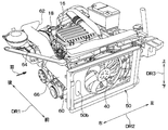
- FIG. 1 is a schematic view of the entire configuration of the cooling module 10 according to the present embodiment as viewed from above the vehicle.
- Arrows DR1 and DR2 in FIG. 1 and an arrow DR3 in FIG. 2 described later indicate the direction of the vehicle 12 on which the cooling module 10 is mounted. That is, the double-ended arrow DR1 in FIG. 1 indicates the vehicle longitudinal direction DR1, the double-ended arrow DR2 indicates the vehicle left-right direction DR2, that is, the vehicle width direction DR2, and the double-ended arrow DR3 in FIG.
- an engine room 14 is formed in the vehicle 12, in other words, in the automobile 12 in front of the automobile 12.
- the cooling module 10 is disposed from the portion between the engine room opening 2 and the traveling engine 16 to the rear of the traveling engine 16 in the vehicle longitudinal direction DR1 in the engine room 14.
- the engine room 14 is a space in which the traveling engine 16 is disposed, and is a front engine room provided in front of the vehicle with respect to the passenger compartment (that is, the passenger compartment) of the automobile 12.
- the engine room opening 2 is an opening that opens in front of the engine room 14 in the vehicle and allows air to pass in the vehicle front-rear direction DR ⁇ b> 1, and is formed in the front grill 4 of the automobile 12. Since the engine room opening 2 is provided in the front grill 4 in this way, for example, outside air in the vehicle compartment, such as traveling wind, that is, outside air passes through the engine room opening 2 and passes through the engine room opening 2 to the engine room 14. Flow into.
- the cooling module 10 includes a capacitor 20, a radiator 30, an electric fan 40, a shroud 50, and an air guide duct 60.
- the shroud 50 and the air guide duct 60 constitute an air guide unit that guides air in the cooling module 10.
- the condenser 20, the radiator 30, the electric fan 40, and the shroud 50 are disposed between the engine room opening 2 and the traveling engine 16 in the vehicle front-rear direction DR1.
- the condenser 20 is a component of an air conditioner that performs air conditioning of the vehicle interior, and constitutes a refrigeration cycle apparatus that circulates refrigerant contained in the air conditioner together with a compressor, a pressure reducing valve, and an evaporator.
- the capacitor 20 is a heat exchanger as a radiator that dissipates heat of the high-pressure refrigerant discharged from the compressor to the outside air and condenses the high-pressure refrigerant.
- the radiator 30 is disposed at the rear of the vehicle with respect to the capacitor 20 and at the front of the vehicle with respect to the electric fan 40.
- the radiator 30 is an engine cooling heat exchanger for cooling the traveling engine 16. Specifically, the radiator 30 cools the traveling engine 16 by dissipating heat of engine cooling water as a heat medium circulating in the traveling engine 16 to the outside air.
- the radiator 30 is disposed on the upstream side with respect to the electric fan 40 in the air flow direction in the introduction flow path 50a.
- the introduction flow path 50a is an air passage for guiding the air flow sucked from the engine room opening 2 through the condenser 20 and the radiator 30 to the electric fan 40 as shown by an arrow K in FIG.
- the air flow direction in the introduction flow path 50a is the flow direction of the main flow having the largest air volume among the plurality of air flows flowing through the introduction flow path 50a.
- the electric fan 40 is, for example, an axial flow blower, and generates an air flow (that is, cooling air) that passes through the condenser 20 and the radiator 30 from the front of the automobile 12 through the engine room opening 2.
- electric fan 40 sucks air that has passed through condenser 20 and radiator 30 from the front of the vehicle, and blows out the sucked air to the rear of the vehicle.
- the shroud 50 is fixed to the vehicle body 6, and the capacitor 20, the radiator 30, and the electric fan 40 are fixed to the shroud 50. They may be fixed directly or indirectly with respect to the shroud 50. In the present embodiment, for example, the radiator 30 and the electric fan 40 are directly fixed to the shroud 50.
- the capacitor 20 is directly fixed to the radiator 30, and is fixed to the shroud 50 through the radiator 30.
- the shroud 50 is a casing that forms an introduction flow path 50a for guiding the air flow sucked from the engine room opening 2 through the condenser 20 and the radiator 30 to the electric fan 40.
- the shroud 50 is an air guide member that guides air (that is, outside air) passing through the condenser 20 and the radiator 30 through the engine room opening 2.
- the shroud 50 is formed so as to surround the space formed between the capacitor 20 and the radiator 30 and the space formed between the radiator 30 and the electric fan 40 in a cylindrical shape.
- the shroud 50 is formed with a ventilation hole 50b through which a part of the air flowing through the introduction flow path 50a flows into the air guide duct 60.
- the ventilation hole 50 b is disposed on the downstream side of the radiator 30 and the upstream side of the electric fan 40 in the air flow in the introduction flow path 50 a. That is, in the vehicle front-rear direction DR ⁇ b> 1, the ventilation holes 50 b of the shroud 50 are disposed behind the radiator 30 and forward of the electric fan 40. Further, the ventilation hole 50b is disposed at a position biased to one of the left and right with respect to the electric fan 40 in the vehicle width direction DR2.
- the air guide duct 60 is an air guide pipe disposed on the upper side of the traveling engine 16 in the engine room 14, and forms an in-duct flow path 60 a, which is an air flow path 60 a through which air flows, in the air guide duct 60. ing.
- the air duct 60 has a front opening 61 as a first opening and a rear opening 62 as a second opening. Air flows between the front opening 61 and the rear opening 62.
- FIG. 2 is a perspective view illustrating the air guide duct 60, the shroud 50, the electric fan 40, and the traveling engine 16 extracted from FIG.
- the rear opening 62 of the air guide duct 60 constitutes an end portion of the air guide duct 60 on the rear side of the vehicle, and opens in the engine room 14 to the rear of the vehicle with respect to the traveling engine 16.
- the rear opening 62 is open to the exhaust manifold 18 side with respect to the traveling engine 16 in the engine room 14.
- the rear side opening 62 forms a duct outlet provided on the side of the air guide duct 60 opposite to the shroud 50 side.
- the rear side opening part 62 should just be the vehicle rear side with respect to the engine 16 for driving
- the air guide duct 60 flows the air flowing in from the front opening 61 to the rear opening 62.
- the air guide duct 60 is composed of two duct members 64 and 66. That is, the air duct 60 includes a downstream duct member 64 as a first duct member and an upstream duct member 66 as a second duct member. In short, the downstream duct member 64 and the upstream duct member 66 are connected in series to form the air guide duct 60.
- the air guide duct 60 has a connection portion between the downstream duct member 64 and the upstream duct member 66 in the middle from the front opening 61 to the rear opening 62. The connection location may be provided at any location of the air guide duct 60.
- the downstream duct member 64 constitutes a downstream portion of the air guide duct 60 in the air flow direction in the air guide duct 60. Therefore, the downstream duct member 64 has the rear opening 62 as a downstream end portion of the downstream duct member 64 in the air flow direction in the air guide duct 60.
- the downstream duct member 64 has a downstream connection portion 641 that is a first connection portion connected to the upstream duct member 66 as an upstream end portion on the side opposite to the rear opening 62 side. .
- the air flow direction in the air guide duct 60 is the air flow direction from the front opening 61 to the rear opening 62 of the air guide duct 60, and the same applies to the description to be described later.
- the downstream duct member 64 has a downstream duct passage 64 a serving as a first duct passage that allows air flowing from the ventilation hole 50 b of the shroud 50 to flow from the downstream connection portion 641 to the rear opening 62. Forming.
- the upstream duct member 66 constitutes an upstream portion of the air guide duct 60 in the air flow direction in the air guide duct 60. That is, the upstream duct member 66 is provided on the upstream side with respect to the downstream duct member 64. In short, the upstream duct member 66 is interposed between the downstream duct member 64 and the shroud 50. Therefore, the upstream duct member 66 has the front opening 61 as an upstream end portion of the upstream duct member 66 in the air flow direction in the air guide duct 60. On the other hand, the upstream duct member 66 has an upstream connection portion 661 that is a second connection portion connected to the downstream connection portion 641 as a downstream end portion on the opposite side to the front opening 61 side. . That is, the upstream duct member 66 has the upstream side connection portion 661 on the downstream duct member 64 side of the upstream duct member 66.
- the upstream duct member 66 forms an upstream duct passage 66a in the upstream duct member 66 as a second duct passage through which air from the ventilation hole 50b of the shroud 50 flows to the downstream duct passage 64a. That is, the upstream duct passage 66 a and the downstream duct passage 64 a are connected to each other to form the in-duct flow path 60 a of the air guide duct 60, and the downstream duct member 64 is connected to the shroud 50 via the upstream duct member 66. Has been.
- the upstream duct member 66 is fixed to the shroud 50 at the front opening 61. Therefore, the upstream side connection portion 661 included in the upstream duct member 66 is also fixed to the shroud 50.
- the upstream duct member 66 may be fixed to the shroud 50 by, for example, integral molding of the upstream duct member 66 and the shroud 50.
- the fixing method may be that the upstream duct member 66 and the shroud 50 are formed as separate parts and then fixed to each other by snap fit or the like.
- the downstream duct member 64 is a member fixed to the traveling engine 16, and is piped on the upper side of the traveling engine 16 in the engine room 14. That is, the downstream duct member 64 is piped between the traveling engine 16 and the hood 70 (see FIG. 9) that forms the upper part of the engine room 14 and can be opened and closed in the vehicle vertical direction DR3 (see FIG. 2). .
- the downstream duct member 64 is assembled from the upper side with respect to the traveling engine 16 as indicated by an arrow AR1 in FIG. 3, and at the same time, at the IV portion in FIG. 3, the downstream side connection part 641 and the upstream side connection part 661. Are connected to each other. In this way, the downstream connection portion 641 and the upstream connection portion 661 are connected to each other, so that the air guide duct 60 can guide the air flowing from the ventilation holes 50b of the shroud 50 to the rear opening 62. become able to.
- 3 is a schematic view of the cooling module 10 and the traveling engine 16 as viewed from the right side of the vehicle in the vehicle width direction DR2 as indicated by an arrow III in FIG. 2, and illustrates an assembling method of the downstream duct member 64.
- FIG. 4 is an enlarged view of a portion corresponding to the IV portion of FIG. 3, and is a cross-sectional view showing a connection structure between the downstream side connection portion 641 and the upstream side connection portion 661.
- FIG. 3 shows a state before the downstream duct member 64 is connected to the upstream duct member 66
- FIG. 4 shows a state after the downstream duct member 64 is connected to the upstream duct member 66. .
- each of the downstream side connection portion 641 and the upstream side connection portion 661 has a cylindrical shape, for example, a cylindrical shape.
- the cylindrical downstream connection part 641 is connected to the rear side opening part 62 via the downstream duct channel
- the downstream connection portion 641 forms an air passage inside the downstream connection portion 641, and the air passage communicates with the rear opening 62 (see FIG. 1) via the downstream duct passage 64a.
- the cylindrical upstream connecting portion 661 communicates with the ventilation hole 50b (see FIG. 2) of the shroud 50 via the upstream duct passage 66a.
- the upstream connection portion 661 forms an air passage inside the upstream connection portion 661, and the air passage communicates with the ventilation hole 50b of the shroud 50 via the upstream duct passage 66a.
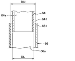
- the thickness DL of the downstream connection portion 641 and the thickness DU of the upstream connection portion 661 are different from each other. In short, the sizes of the cylinders of both connection portions 641 and 661 are different from each other. And one connection part of the downstream connection part 641 and the upstream connection part 661 is inserted in the other connection part.
- the downstream side connection portion 641 is formed thinner than the upstream side connection portion 661, and the downstream side connection portion 641 is inserted into the upstream side connection portion 661. Accordingly, the thickness DL of the downstream connection portion 641 is specifically the outer diameter of the downstream connection portion 641, and the thickness DU of the upstream connection portion 661 is specifically the inner diameter of the upstream connection portion 661. It is.
- the downstream side connection part 641 is inserted into the upstream side connection part 661, whereby the downstream duct member 64 is connected to the shroud 50 via the upstream duct member 66.
- the downstream side connection portion 641 is provided so as to overlap with the upstream side connection portion 661 in the radial direction.
- the downstream connection portion 641 is inserted into the upstream connection portion 661 in the vehicle vertical direction DR3 (see FIG. 2).
- the downstream connection portion 641 and the upstream connection portion 661 are configured such that the downstream duct member 64 can be removed from the shroud 50, respectively.
- each of the downstream side connection portion 641 and the upstream side connection portion 661 is configured such that the downstream duct member 64 can be removed from the upstream duct member 66 fixed to the shroud 50.
- the exhaust manifold 18 is a manifold that collects a plurality of exhaust passages connected to the traveling engine 16 into one exhaust pipe that discharges exhaust gas from the traveling engine 16.
- the exhaust manifold 18 is disposed in the rear of the vehicle with respect to the traveling engine 16 in the engine room 14.
- a turbocharger turbine and a catalyst device are arranged in addition to the exhaust manifold 18 at the rear of the engine room 14 with respect to the traveling engine 16.
- the catalyst device is a device that purifies harmful components in exhaust gas blown from the traveling engine 16 by reduction and oxidation.
- the turbocharger extracts rotational energy from the internal energy of the exhaust gas blown out from the traveling engine 16 by the turbine, operates the compressor by this rotational energy, generates compressed air, and supplies the compressed air to the intake port of the traveling engine 16.
- a turbocharger turbine is a device that extracts rotational energy from internal energy of exhaust gas.
- the duct 60 is introduced into the in-duct flow path 60a.
- the air flow introduced into the in-duct flow path 60a is blown out from the rear opening 62 of the air guide duct 60 to the exhaust manifold 18 side. Therefore, the exhaust manifold 18, the catalyst device, and the turbocharger turbine disposed in the engine rear space in the engine room 14 are cooled by the air that is guided to the air guide duct 60 and blown out from the rear opening 62.
- the engine rear space is a space behind the vehicle with respect to the traveling engine 16 in the engine room 14.
- the air flow that has cooled the exhaust manifold 18, the catalyst device, and the turbocharger turbine in this way flows below the floor of the exhaust manifold 18.
- an air flow that flows around the engine room opening 2, the condenser 20, the radiator 30, the air guide duct 60, and the exhaust manifold 18 and flows under the floor of the automobile 12 is generated.
- the remaining air flow other than the air flow flowing into the air guide duct 60 is an electric fan. Inhaled into 40. The remaining air sucked in by the electric fan 40 passes around the traveling engine 16 and flows below the floor. For this reason, the traveling engine 16 is cooled by the airflow that flows from the introduction flow path 50a through the electric fan 40 to the traveling engine 16 side.
- the engine rear space in the engine room 14 can be cooled as described above. That is, it is possible to cool the exhaust manifold 18, the catalyst device, and the turbocharger turbine disposed in the engine rear space. For this reason, for example, it is possible to avoid heat damage from occurring in the exhaust manifold 18, the catalyst device, the turbocharger turbine, and its peripheral components.
- the air duct 60 includes a downstream duct member 64 as a part of the air duct 60, and the downstream duct member 64 is configured to allow the downstream duct member 64 to be removed from the shroud 50.
- a portion 641 is provided on the side opposite to the rear opening 62 side. Accordingly, the downstream duct member 64 can be separated from the shroud 50 and removed from the engine room 14 without removing the shroud 50 from the engine room 14. As a result, it is possible to suppress deterioration in serviceability related to the traveling engine 16 due to the air guide duct 60. For example, when performing work related to the traveling engine 16 or its peripheral devices, the worker can remove only the downstream duct member 64 on the upper side of the traveling engine 16 from the cooling module 10. .
- downstream duct member 64 can be removed from the shroud 50, it is not necessary to install the shroud 50, the downstream duct member 64, and the upstream duct member 66 in the engine room 14 at the same time. Therefore, it is possible to satisfactorily secure the assembling property when the air guide duct 60 is installed in the engine room 14. For example, the operator can install the downstream duct member 64 after installing the shroud 50 and the upstream duct member 66 fixed to the shroud 50 in the engine room 14.
- downstream duct member 64 fixed to the traveling engine 16 and the upstream duct member 66 fixed to the vehicle body 6 via the shroud 50 are separate members. Therefore, a vibration phase difference can be absorbed between the upstream duct member 66 to which the vibration of the vehicle body 6 is transmitted and the downstream duct member 64 to which the vibration of the traveling engine 16 is transmitted. Therefore, the vibration durability of the shroud 50 and the air guide duct 60 can be satisfactorily ensured.
- the downstream side connection portion 641 and the upstream side connection portion 661 both have a cylindrical shape, and the upstream side connection portion 661 communicates with the ventilation hole 50b of the shroud 50 through the upstream duct passage 66a. is doing.
- the downstream connection portion 641 is inserted into the upstream connection portion 661, whereby the downstream duct member 64 is connected to the shroud 50 via the upstream duct member 66. Therefore, the downstream duct member 64 and the upstream duct member 66 can be connected with a simple structure so as to allow ventilation.
- the downstream duct member 64 is connected to the shroud 50 via the upstream duct member 66. Therefore, it is easy to lay out the connection portion between the downstream duct member 64 and the upstream duct member 66 at a desired position without being restricted by the arrangement of the shroud 50. For example, the connection location between the duct members 64 and 66 can be laid out at a position where connection work is facilitated.
- the front opening 61 of the air guide duct 60 is connected to the shroud 50 through the ventilation holes 50 b of the shroud 50. For this reason, it is possible to reduce the resistance of the air flow that passes through the radiator 30 through the engine room opening 2 when the automobile 12 is traveling at high speed. For example, the amount of air passing through the radiator 30 can be equivalent to the amount of air blown when a conventional electric fan 40 having a ram pressure hole in the shroud 50 is used. As a result, the cooling capacity for cooling the radiator 30 can be improved.
- FIG. 5 is a diagram showing a different point from the first embodiment in the cooling module 10 of the present embodiment, and shows a connection structure between the downstream connection portion 641 and the upstream connection portion 661 as in FIG. It is sectional drawing.
- the air guide duct 60 has a sealing material 68. This point is different from the first embodiment.
- the sealing material 68 of the air guide duct 60 is made of an elastic body such as rubber or urethane foam.
- the sealing material 68 is provided over the entire circumference of the radial gap formed between the downstream connection portion 641 and the upstream connection portion 661, and is compressed in the radial direction by both the connection portions 641 and 661. ing. Thereby, the sealing material 68 closes the radial gap between the downstream side connection portion 641 and the upstream side connection portion 661.
- the downstream duct member 64 is assembled from the upper side with respect to the traveling engine 16 as indicated by the arrow AR1 in FIG. 3 described above.
- the downstream duct member 64 constitutes a part of the engine cover 72. Yes. That is, the downstream duct member 64 is used as a part of the engine cover 72. This point is different from the first embodiment.
- the engine cover 72 of this embodiment is made of, for example, resin and is integrally formed including the downstream duct member 64.
- the engine cover 72 is disposed in the engine room 14 and covers at least a part of the upper side of the traveling engine 16.
- the engine cover 72 serves to prevent engine noise generated from the traveling engine 16, for example.
- the engine cover 72 is fixed to the traveling engine 16 by bolt fastening or the like. In short, the engine cover 72 is detachably fixed to the traveling engine 16. Therefore, the downstream duct member 64 included in the engine cover 72 can also be removed from the traveling engine 16.
- downstream duct member 64 constitutes a part of the engine cover 72, the downstream duct member 64 can be removed together in the operation of removing the engine cover 72 from the traveling engine 16. is there.
- this embodiment is a modification based on 1st Embodiment, it is also possible to combine this embodiment with the above-mentioned 2nd Embodiment.
- FIG. 6 is a view showing a difference from the first embodiment in the cooling module 10 of the present embodiment, and is a cross-sectional view showing a connection structure between the downstream side connection portion 641 and the upstream side connection portion 661.
- the air guide duct 60 includes only the duct member 64 corresponding to the downstream duct member 64 as the first duct member among the two duct members 64 and 66 in the first embodiment, and the upstream duct member. No member corresponding to 66 is provided. Therefore, the upstream side connection portion 661 as the second connection portion is directly provided on the shroud 50 as shown in FIG. The duct member 64 is directly connected to the shroud 50. These points are different from the first embodiment.
- the downstream connection portion 641 and the upstream connection portion 661 both have a cylindrical shape, and the downstream connection portion 641 is inserted into the upstream connection portion 661.
- the upstream side connection portion 661 includes an inner peripheral side surface 661a facing the downstream side connection portion 641, and a concave portion 661b formed on the inner peripheral side surface 661a and recessed from the inner peripheral side surface 661a.
- the downstream side connection portion 641 has an outer peripheral side surface 641a that faces the inner peripheral side surface 661a, and a convex portion 641b that protrudes from the outer peripheral side surface 641a and engages with the concave portion 661b.
- the convex portion 641b and the concave portion 661b are formed over the entire circumference of the downstream side connecting portion 641 and the upstream side connecting portion 661, and the convex portion 641b is fitted into and engaged with the concave portion 661b over the entire circumference.
- the convex portion 641b of the downstream side connecting portion 641 is engaged with the concave portion 661b of the upstream side connecting portion 661. Therefore, it is possible to connect the downstream side connection portion 641 to the upstream side connection portion 661 so that the downstream side connection portion 641 of the duct member 64 does not easily come off from the upstream side connection portion 661 of the shroud 50.
- this embodiment is a modification based on 1st Embodiment, it is also possible to combine this embodiment with the above-mentioned 2nd Embodiment or 3rd Embodiment.
- FIG. 7 is a view showing a difference from the fourth embodiment in the cooling module 10 of the present embodiment, and is a cross-sectional view showing a connection structure between the downstream side connection portion 641 and the upstream side connection portion 661.
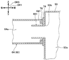
- the convex part 641b of the downstream connection part 641 and the concave part 661b (see FIG. 6) of the upstream connection part 661 are not provided, and the downstream connection part 641 and the upstream connection part 661 are permanent magnets. It is connected using the magnetic force of 74. This point is different from the first embodiment.
- the downstream connection portion 641 and the upstream connection portion 661 both have a cylindrical shape, and the upstream connection portion 661 is inserted into the downstream connection portion 641. .
- the upstream side connection portion 661 has a permanent magnet 74 at the proximal end portion of the upstream side connection portion 661.
- the downstream connection portion 641 has a member 76 to be attracted to the permanent magnet 74 by the magnetic force of the permanent magnet 74 at the distal end portion of the downstream connection portion 641.
- the permanent magnet 74 of the upstream connection portion 661 draws the attracted member 76 in the axial direction of the downstream connection portion 641 and the upstream connection portion 661 by its magnetic force.
- the attracted member 76 is made of, for example, an iron plate or a magnet that attracts the permanent magnet 74 of the upstream connection portion 661 by a magnetic force.
- the duct member 64 is connected to the shroud 50 by connecting the downstream connection portion 641 and the upstream connection portion 661 with a magnetic force generated between the permanent magnet 74 and the attracted member 76.
- a magnetic force generated between the permanent magnet 74 and the attracted member 76 are connected to each other.
- the permanent magnet 74 and the attracted member 76 are in close contact with each other by magnetic force, it is possible to ensure a sufficient sealing property between the downstream connection portion 641 and the upstream connection portion 661.
- the upstream connection portion 661 is inserted into the downstream connection portion 641 longer than the distance that the magnetic force of the permanent magnet 74 reaches the attracted member 76 in the axial direction of the upstream connection portion 661. Accordingly, even if the permanent magnet 74 and the attracted member 76 are slightly separated in the axial direction of the upstream connection portion 661 due to vibration or the like, the upstream connection portion 661 is prevented from dropping from the downstream connection portion 641. Is possible. Then, the positional relationship between the permanent magnet 74 and the attracted member 76 can be restored to the state before they are separated by the magnetic force of the permanent magnet 74.
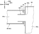
- the permanent magnet 74 and the attracted member 76 are abutted in the axial direction of the downstream side connection portion 641 and the upstream side connection portion 661. Then, one of the permanent magnet 74 and the member to be attracted 76 is formed so as to extend wider in the radial direction of the downstream side connection portion 641 and the upstream side connection portion 661 than the other. In the present embodiment, the permanent magnet 74 is formed so as to expand wider in the radial direction than the attracted member 76. Therefore, as shown in FIG.
- played from the structure common to the above-mentioned 4th Embodiment can be acquired similarly to 4th Embodiment.
- this embodiment is a modification based on 4th Embodiment, it is also possible to combine this embodiment with the above-mentioned 3rd Embodiment.
- FIG. 9 and FIG. 10 are views showing points different from the first embodiment in the cooling module 10 of the present embodiment.
- the cooling module 10, the traveling engine 16, the bonnet 70 and the like are arranged in the vehicle width direction DR2. It is the schematic diagram seen from the right side.
- FIG. 9 shows a state where the hood 70 is opened
- FIG. 10 shows a state where the hood 70 is closed.
- downstream duct member 64 is not fixed to the traveling engine 16 but is fixed to the bonnet 70. This point is different from the first embodiment. Further, the configurations of the downstream side connection portion 641 and the upstream side connection portion 661 are also different from those of the first embodiment.
- the downstream duct member 64 is integrally fixed to the bonnet 70 by bolting or the like, for example.
- the bonnet 70 is connected to the vehicle body 6 via a hinge. Accordingly, the bonnet 70 opens and closes while rotating around the hinge.
- the downstream connection part 641 and the upstream connection part 661 are made of a material having elasticity such as rubber, and are formed in an annular shape so that air passes through the inside, for example.
- the upstream connection portion 661 is disposed below the downstream connection portion 641.
- the downstream duct member 64 rotates together with the bonnet 70, and when the bonnet 70 opens the upper part of the engine room 14, it is separated from the upstream duct member 66 and the shroud 50 as shown in FIG. That is, in that case, the downstream connection portion 641 is also separated from the upstream connection portion 661.
- downstream duct member 64 In the downstream duct member 64, when the bonnet 70 closes the upper portion of the engine room 14, the downstream connection portion 641 and the upstream connection portion 661 are brought into close contact with each other as shown in FIG.
- the downstream duct passage 64a and the upstream duct passage 66a (see FIG. 1) communicate with each other. That is, in that case, the downstream duct member 64 is connected to the shroud 50 via the upstream duct member 66 by connecting the downstream connection portion 641 and the upstream connection portion 661 to each other.
- the downstream side connection portion 641 and the upstream side connection portion 661 are in close contact with each other, so that at the connection portion between the downstream duct member 64 and the upstream duct member 66. Sealability is ensured.
- the broken line arrow in FIG. 10 shows the flow of the exhaust of the traveling engine 16
- the solid line arrow shows the flow of the cooling air introduced into the air guide duct 60 from the front of the vehicle.
- the cooling air is guided to the rear of the traveling engine 16, and the exhaust manifold 18 is cooled.
- the downstream duct member 64 is fixed to the bonnet 70 and rotates together with the bonnet 70. Therefore, there is an advantage that it is not necessary to remove the downstream duct member 64 when the worker performs work related to the traveling engine 16 or its peripheral devices.
- FIG. 11 is a diagram showing points different from the first embodiment in the cooling module 10 of the present embodiment, in which the downstream side connection portion 641 and the upstream side connection portion 661 are cut in a cross section orthogonal to the axial direction thereof. It is sectional drawing.
- the cooling module 10 of this embodiment includes a locking structure that locks the downstream side connection portion 641 to the upstream side connection portion 661. This point is different from the first embodiment.
- the downstream connection portion 641 and the upstream connection portion 661 both have a cylindrical shape, and the downstream connection portion 641 is inserted into the upstream connection portion 661.
- the downstream connection part 641 has the outer peripheral side surface 641a which opposes the upstream connection part 661, and the string part 78 which extends from the outer peripheral side surface 641a and comprises a string shape.
- the string portion 78 has flexibility, and is integrally formed including a plurality of knob portions 781 and 782 that locally swell in the middle of the string portion 78.
- a plurality of string portions 78 specifically two, are provided, but the number and arrangement of the string portions 78 are not limited to those shown in FIG.
- the knob portions 781 and 782 of the string portion 78 are made of a material having elasticity such as rubber.
- the bumps 781 and 782 are formed in a spherical shape as shown in FIG. 12, and the insides of the bumps 781 and 782 are hollow. Thereby, the knob parts 781 and 782 are easily deformed by applying an external force. For example, as shown in FIG. 13, when an external force F1 is applied to the string portion 78 and the string portion 78 is pulled, the knob portion 781 extends in the longitudinal direction of the string portion 78 and deforms thinly. Therefore, by deforming the bumps 781 and 782 as shown in FIG.
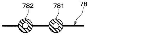
- FIG. 12 is a cross-sectional view showing a single string portion 78
- FIG. 13 is a cross-sectional view showing a state in which the knob portion 781 is deformed by an external force F1 in the same cross section as FIG.
- the upstream connection portion 661 is formed with an insertion hole 78a penetrating the upstream connection portion 661 in the plate thickness direction.
- the insertion holes 78a are provided in the same number as the number of the string portions 78, and are formed to be smaller than the outer diameters of the knob portions 781 and 782.
- FIG. 14 which is a sectional view of XIV-XIV in FIG. 11, the plurality of string portions 78 of the downstream connection portion 641 are inserted into the plurality of insertion holes 78a of the upstream connection portion 661, respectively. Yes.
- the insertion hole 78 a is disposed between the connection end 783 of the string portion 78 and the knob portion 781.
- at least one knob portion 781 of the plurality of knob portions 781 and 782 included in the string portion 78 is disposed outside the upstream connection portion 661.
- the connection end 783 of the string portion 78 is an end portion of the string portion 78 that is connected to the outer peripheral side surface 641 a of the downstream connection portion 641.
- the positional relationship between the downstream side connection portion 641 and the upstream side connection portion 661 is normally as shown in FIG. 14, but as shown in FIG. 15, the external force F2 pulls the downstream side connection portion 641 from the upstream side connection portion 661. Sometimes added in the direction of leaving. When the external force F2 is applied in this manner, the downstream connection portion 641 is somewhat disengaged from the upstream connection portion 661 as shown in FIG. Is done. Therefore, it is possible to prevent the downstream duct member 64 (see FIG. 1) from dropping from the upstream duct member 66.
- played from the structure common to the above-mentioned 1st Embodiment can be acquired similarly to 1st Embodiment.
- this embodiment is a modification based on 1st Embodiment, it is also possible to combine this embodiment with the above-mentioned 2nd Embodiment or 3rd Embodiment.
- the air guide duct 60 is composed of the two duct members 64 and 66, but this is an example.
- the air guide duct 60 has only a duct member corresponding to the downstream duct member 64 of the two duct members 64 and 66, that is, a first duct member, and the first duct member is directly connected to the shroud 50. It does not matter.
- the first duct member may constitute a part of the air duct 60 or may constitute the entire air duct 60.
- the upstream duct member 66 is not provided, and therefore the connection portion corresponding to the upstream side connection portion 661, that is, the second connection portion is the shroud 50. Provided directly.
- the second, third, sixth, and seventh embodiments are identical to the second, third, sixth, and seventh embodiments.
- the air guide duct 60 does not have a member corresponding to the upstream duct member 66 of the first embodiment, but this is an example.
- the air duct 60 may include the upstream duct member 66 as in the first embodiment, and the duct member 64 as the downstream duct member 64 connected to the upstream duct member 66. .
- the engine room opening 2 is formed in the front grill 4 of the automobile 12, but is not limited thereto, and is formed, for example, in the lower front surface of the front bumper of the automobile 12. There is no problem.
- the cylindrical downstream connection portion 641 is inserted into the cylindrical upstream connection portion 661 as shown in FIG. 4, but conversely as shown in FIG.
- the upstream connection portion 661 may be inserted into the downstream connection portion 641.
- the thickness DL of the downstream connection portion 641 specifically represents the inner diameter of the downstream connection portion 641
- the thickness DU of the upstream connection portion 661 is specifically Represents the outer diameter of the upstream connecting portion 661.
- the convex portion 641b is fitted and engaged with the concave portion 661b over the entire circumference of the downstream side connecting portion 641 and the upstream side connecting portion 661, but a part of the entire circumference It does not matter even if it only fits into the recess 661b.
- the downstream side connection portion 641 when the downstream side connection portion 641 is located on the lower side inside the upstream side connection portion 661, the lower portions of the convex portion 641b and the concave portion 661b may be engaged with each other.
- the downstream connection part 641 is located on the upper side inside the upstream connection part 661, the upper part of the convex part 641b and the concave part 661b may be engaged with each other.
- the downstream connection portion 641 vibrates in the vehicle width direction DR2 (see FIG. 1) or the vehicle vertical direction DR3 (see FIG. 2) with respect to the upstream connection portion 661
- the downstream connection portion 641 and the upstream connection portion may be engaged with each other at any part of the entire circumference of 661.
- the downstream connection portion 641 is inserted into the upstream connection portion 661 as shown in FIG. 6, but this is an example.
- the upstream side connection portion 661 may be inserted into the downstream side connection portion 641.
- the downstream side connection portion 641 has a concave portion 661b
- the upstream side connection portion 661 has a convex portion 641b.
- the upstream connection portion 661 has a recess 661b, and the downstream connection portion 641 inserted inside the upstream connection portion 661 has a protrusion 641b.
- the upstream side connection portion 661 may have a convex portion 661c, and the downstream side connection portion 641 may have a concave portion 641c.
- the downstream connection portion 641 has a recess 641c formed on the outer peripheral side surface 641a of the downstream connection portion 641 and recessed from the outer peripheral side surface 641a.
- the upstream connection part 661 has the convex part 661c which protrudes from the internal peripheral side surface 661a of the upstream connection part 661, and engages with the recessed part 641c.
- the upstream connection portion 661 has the permanent magnet 74 and the downstream connection portion 641 has the attracted member 76, but conversely, the upstream connection portion 661 has Even if it has the member to be attracted 76 and the downstream side connection portion 641 has the permanent magnet 74, there is no problem.
- the downstream connection portion 641 has a string portion 78, and the upstream connection portion 661 disposed outside the downstream connection portion 641 has an insertion hole.
- 78a is formed, but this is an example.
- an insertion hole 78 a may be formed in the downstream connection portion 641, and the upstream connection portion 661 may have the string portion 78. If it does so, the upstream connection part 661 has the string part 78 extended from the inner peripheral side surface 661a of the upstream connection part 661, and the connection end 783 of the string part 78 is connected to the inner peripheral side surface 661a. Is done.
- the insertion hole 78 a of the downstream connection portion 641 is disposed between the connection end 783 of the string portion 78 and the knob portion 781.
- the cooling module 10 includes the radiator 30 as an engine cooling heat exchanger. Instead, an oil cooler that cools engine oil as a heat medium is engine-cooled. It may be provided as a heat exchanger for use.
- the air guide duct 60 is disposed on the upper side of the traveling engine 16 in the engine room 14, but may be disposed at a position other than the upper side of the traveling engine 16. Absent.
- the engine room opening 2 is provided in front of the vehicle with respect to the radiator 30.
- the engine room opening 2 is offset in the vehicle width direction DR2 with respect to the radiator 30. It may be provided at a different position.
- the exhaust manifold 18 is disposed in the engine room 14 at the rear of the vehicle with respect to the traveling engine 16, but at a position other than the rear of the vehicle with respect to the traveling engine 16. It may be arranged.
- the electric fan 40 is described as being an axial-flow fan, for example, but may be a fan other than the axial-flow fan, for example, a centrifugal fan.
- the capacitor 20, the radiator 30, and the electric fan 40 are arranged in the order of the capacitor 20, the radiator 30, and the electric fan 40 from the front of the vehicle.
- the arrangement order is not limited. It's okay.
Landscapes
- Engineering & Computer Science (AREA)
- Chemical & Material Sciences (AREA)
- Combustion & Propulsion (AREA)
- Mechanical Engineering (AREA)
- Transportation (AREA)
- General Engineering & Computer Science (AREA)
- Cooling, Air Intake And Gas Exhaust, And Fuel Tank Arrangements In Propulsion Units (AREA)
Abstract
導風ユニットは、シュラウド(50)と導風ダクト(60)とを備える。そのシュラウドは、エンジンルーム開口部を経て放熱器(20)およびエンジン冷却用熱交換器(30)を通過する空気を案内する。導風ダクトは、シュラウドの通風孔にてシュラウドに接続されその通風孔を通して開口する第1開口部(61)と、エンジンルーム内のうち走行用エンジンに対する車両後方に開口する第2開口部(62)とを有する。そして、導風ダクトは第1開口部と第2開口部との間に空気を流す。また、導風ダクトは、その導風ダクトの少なくとも一部を構成し且つ第2開口部を有すると共に通風孔からの空気を第2開口部へ流す第1ダクト通路(64a)を形成する第1ダクト部材(64)を含む。その第1ダクト部材は、シュラウドから第1ダクト部材を取り外すことができるように構成された第1接続部(641)を、第2開口部側とは反対側に有している。
Description
本出願は、2015年7月27日に出願された日本特許出願番号2015-147751号に基づくもので、ここにその記載内容が参照により組み入れられる。
本開示は、自動車のエンジンルームに設けられる導風ユニットおよび冷却モジュールに関するものである。
上記の導風ユニットのように空気を導くものの1つとして、例えば、特許文献1に記載された車両のインタークーラ冷却用ダクトが知られている。そのインタークーラ冷却用ダクトは、車両のエンジンフードのエンジンルーム側に形成された空気吹出口とインタークーラの空気取入口とをつなぐダクトである。
具体的にその特許文献1のインタークーラ冷却用ダクトは、エンジンフードの空気吹出口に連結された上端開口と、エンジンフードの閉時においてインタークーラの空気取入口に対して衝合させられる下端開口とを備えている。そして、インタークーラ冷却用ダクトは、エンジンフード内を通過して上記空気吹出口から出た外気をインタークーラに送給する。
自動車の例えばエンジンルームには、冷却機能を果たす冷却モジュール、言い換えればクーリングモジュールが設けられている。そのクーリングモジュールは、エンジン冷却水を放熱させるラジエータと、車室内の空調を行う空調装置の放熱器であるコンデンサと、冷却風を起こす送風機と、それらを固定し冷却風を案内するシュラウドとから構成されている。そして、空調装置で循環する冷媒の熱やエンジン冷却水の熱は、走行風や送風機による冷却風によって放熱されている。
しかし、自動車のレイアウト上、クーリングモジュールは通常、エンジンルーム内の前方に配置される。そのため、クーリングモジュールが捨てた熱、すなわちラジエータおよびコンデンサにて外気へ移った熱は、クーリングモジュールに対して車両後方に配置された走行用エンジンに流れるので、放熱効率を低下させる原因となっている。
また近年、エンジンルームの縮小化および走行用エンジンの後方排気化に伴い、エンジンルーム内のうち走行用エンジンに対する車両後方のエンジン後方空間に熱がこもりやすくなり、その周辺の電子部品などへ熱害を与える可能性が高まってきている。
そこで、発明者らは、例えば車両前方からエンジンルーム内へ流入する前面風を上記エンジン後方空間へ導くダクトを設けることを考えた。しかし、そのように単にダクトを設けたとすれば、例えばエンジンプラグ交換など走行用エンジンに関わるサービス性を悪化させるという新たな事態が生じると考えられた。
また、この新たな事態を回避するために、特許文献1のインタークーラ冷却用ダクトをクーリングモジュールに適用しようとしても、そのインタークーラ冷却用ダクトはそもそもクーリングモジュールに設けられるものではないので適用することができない。
本開示は上記点に鑑みて、走行用エンジンに関わるサービス性の悪化を抑えつつ、エンジンルーム内のうち走行用エンジンに対する車両後方の空間を冷却することが可能な導風ユニットおよび冷却モジュールを提供することを目的とする。
上記目的を達成するため、本開示の1つの観点によれば、本開示の導風ユニットは、
走行用エンジンが配置されるエンジンルームの車両前方にて開口したエンジンルーム開口部からエンジンルーム内へ空気が流入する自動車に適用される導風ユニットであって、
空調装置の放熱器と走行用エンジンを冷却するためのエンジン冷却用熱交換器と送風機とが固定され、エンジンルーム開口部を経て放熱器およびエンジン冷却用熱交換器を通過する空気を案内し、通風孔が形成されたシュラウドと、
通風孔にてシュラウドに接続されその通風孔を通して開口する第1開口部とエンジンルーム内のうち走行用エンジンに対する車両後方に開口する第2開口部とを有し、第1開口部と第2開口部との間に空気を流す導風ダクトとを備え、
その導風ダクトは、その導風ダクトの少なくとも一部を構成し且つ第2開口部を有すると共に通風孔からの空気を第2開口部へ流す第1ダクト通路を形成する第1ダクト部材を含み、
その第1ダクト部材は、シュラウドから第1ダクト部材を取り外すことができるように構成された第1接続部を第2開口部側とは反対側に有している。
走行用エンジンが配置されるエンジンルームの車両前方にて開口したエンジンルーム開口部からエンジンルーム内へ空気が流入する自動車に適用される導風ユニットであって、
空調装置の放熱器と走行用エンジンを冷却するためのエンジン冷却用熱交換器と送風機とが固定され、エンジンルーム開口部を経て放熱器およびエンジン冷却用熱交換器を通過する空気を案内し、通風孔が形成されたシュラウドと、
通風孔にてシュラウドに接続されその通風孔を通して開口する第1開口部とエンジンルーム内のうち走行用エンジンに対する車両後方に開口する第2開口部とを有し、第1開口部と第2開口部との間に空気を流す導風ダクトとを備え、
その導風ダクトは、その導風ダクトの少なくとも一部を構成し且つ第2開口部を有すると共に通風孔からの空気を第2開口部へ流す第1ダクト通路を形成する第1ダクト部材を含み、
その第1ダクト部材は、シュラウドから第1ダクト部材を取り外すことができるように構成された第1接続部を第2開口部側とは反対側に有している。
上述の開示によれば、導風ダクトは、シュラウドの通風孔にてシュラウドに接続されその通風孔を通して開口する第1開口部とエンジンルーム内のうち走行用エンジンに対する車両後方に開口する第2開口部とを有する。そして、導風ダクトは、その第1開口部と第2開口部との間に空気を流す。従って、エンジンルーム内のうち走行用エンジンに対する車両後方の空間を、導風ダクトに導かれる空気によって冷却することが可能である。
そして、導風ダクトは第1ダクト部材を含み、その第1ダクト部材は、シュラウドから第1ダクト部材を取り外すことができるように構成された第1接続部を第2開口部側とは反対側に有している。そのため、シュラウドをエンジンルーム内から取り外さなくても、第1ダクト部材をシュラウドから分離してエンジンルーム内から取り外すことが可能である。従って、走行用エンジンに関わるサービス性が導風ダクトに起因して悪化することを抑えることが可能である。
以下、本開示の実施形態について図に基づいて説明する。なお、以下の各実施形態相互において、互いに同一もしくは均等である部分には、図中、同一符号を付してある。
(第1実施形態)
図1は、本実施形態における冷却モジュール10の全体構成を車両上側から視た模式図である。図1の矢印DR1、DR2および後述する図2の矢印DR3は、冷却モジュール10が搭載された車両12の向きを示す。すなわち、図1の両端矢印DR1は車両前後方向DR1を示し、両端矢印DR2は車両左右方向DR2すなわち車両幅方向DR2を示し、図2の両端矢印DR3は車両上下方向DR3を示している。
図1は、本実施形態における冷却モジュール10の全体構成を車両上側から視た模式図である。図1の矢印DR1、DR2および後述する図2の矢印DR3は、冷却モジュール10が搭載された車両12の向きを示す。すなわち、図1の両端矢印DR1は車両前後方向DR1を示し、両端矢印DR2は車両左右方向DR2すなわち車両幅方向DR2を示し、図2の両端矢印DR3は車両上下方向DR3を示している。
図1に示すように、車両12言い換えれば自動車12には、自動車12のうちの車両前方にエンジンルーム14が形成されている。そして、冷却モジュール10は、そのエンジンルーム14のうち、車両前後方向DR1においてエンジンルーム開口部2と走行用エンジン16との間の部位から走行用エンジン16の後方にかけて配置されている。
ここで、エンジンルーム14は、走行用エンジン16が配置される空間であって、自動車12のうち乗員室(すなわち、車室)に対して車両前方に設けられたフロントエンジンルームである。また、エンジンルーム開口部2は、エンジンルーム14の車両前方にて開口して車両前後方向DR1に空気が通過する開口部であり、自動車12のフロントグリル4に形成されている。このようにフロントグリル4にエンジンルーム開口部2が設けられているので、例えば走行風などの車室外空気すなわち外気は、そのエンジンルーム開口部2を通り抜け、エンジンルーム開口部2からエンジンルーム14内へ流入する。
具体的には図1に示すように、冷却モジュール10は、コンデンサ20、ラジエータ30、電動ファン40、シュラウド50、および導風ダクト60を備えている。このシュラウド50および導風ダクト60は全体として、冷却モジュール10において空気を導く導風ユニットを構成している。
冷却モジュール10のうちコンデンサ20、ラジエータ30、電動ファン40、およびシュラウド50は、車両前後方向DR1においてエンジンルーム開口部2と走行用エンジン16との間に配置されている。コンデンサ20は、車室内の空調を行う空調装置の一構成要素であり、その空調装置に含まれ冷媒を循環させる冷凍サイクル装置を、圧縮機、減圧弁、および蒸発器とともに構成する。詳細に、コンデンサ20は、圧縮機から吐出される高圧冷媒の熱を外気へ放熱させてその高圧冷媒を凝縮させる放熱器としての熱交換器である。
ラジエータ30は、コンデンサ20に対して車両後方で且つ電動ファン40に対して車両前方に配置されている。ラジエータ30は、走行用エンジン16を冷却するためのエンジン冷却用熱交換器である。ラジエータ30は、具体的には、走行用エンジン16内を循環する熱媒体としてのエンジン冷却水の熱を外気へ放熱させることにより走行用エンジン16を冷却する。
また、ラジエータ30は、導入流路50a内の空気流れ方向において電動ファン40に対し上流側に配置されている。導入流路50aは、エンジンルーム開口部2から吸い込んだ空気流を図1中矢印Kの如くコンデンサ20およびラジエータ30を通過して電動ファン40に導くための空気通路である。導入流路50a内の空気流れ方向とは、導入流路50aを流れる複数の空気流のうち風量が最も多い主流の流れ方向のことである。
電動ファン40は、例えば軸流式の送風機であり、自動車12の前方からエンジンルーム開口部2を通してコンデンサ20およびラジエータ30を通過させる空気流(すなわち冷却風)を発生させる。言い換えれば、電動ファン40は、コンデンサ20およびラジエータ30を通過した空気を車両前方から吸い込むと共に、その吸い込んだ空気を車両後方へ吹き出す。
シュラウド50は車両ボデー6に固定されており、シュラウド50には、コンデンサ20とラジエータ30と電動ファン40とが固定されている。それらは、シュラウド50に対して直接的に固定されていても間接的に固定されていても構わない。本実施形態では例えば、ラジエータ30および電動ファン40はシュラウド50に直接固定されている。そして、コンデンサ20は直接にはラジエータ30に固定され、そのラジエータ30を介してシュラウド50に固定されている。
また、シュラウド50は、エンジンルーム開口部2から吸い込んだ空気流をコンデンサ20およびラジエータ30を通過して電動ファン40に導くための導入流路50aを形成するケーシングである。言い換えれば、シュラウド50は、エンジンルーム開口部2を経てコンデンサ20およびラジエータ30を通過する空気(すなわち外気)を案内する導風部材である。シュラウド50は、コンデンサ20とラジエータ30との間に形成される空間と、ラジエータ30と電動ファン40との間に形成される空間とをそれぞれ筒状に取り囲むように形成されている。
また、シュラウド50には、導入流路50aを流れる空気の一部を導風ダクト60内へ流入させる通風孔50bが形成されている。その通風孔50bは、導入流路50a内の空気流れにおいてラジエータ30の下流側で且つ電動ファン40の上流側に配置されている。すなわち、車両前後方向DR1で言えば、シュラウド50の通風孔50bは、ラジエータ30に対し車両後方で且つ電動ファン40に対し車両前方に配置されている。また、その通風孔50bは、車両幅方向DR2において電動ファン40に対し左右の一方に偏った位置に配置されている。
導風ダクト60は、エンジンルーム14内において走行用エンジン16の上側に配置された導風管であり、空気を流す空気流路60aであるダクト内流路60aを導風ダクト60内に形成している。具体的に、導風ダクト60は、第1開口部としての前側開口部61と、第2開口部としての後側開口部62とを有し、導風ダクト60のダクト内流路60aは、その前側開口部61と後側開口部62との間に空気を流す。
導風ダクト60の前側開口部61は、図1および図2に示すように、導風ダクト60のうち車両前方の端部を構成し、通風孔50bにてシュラウド50に接続されると共にその通風孔50bを通して導入流路50aに開口している。そして、前側開口部61は、ラジエータ30に向かって、要するに車両前方を向いて開口している。このように、前側開口部61は、導風ダクト60のシュラウド50側に設けられたダクト入口を形成している。図2は、図1の導風ダクト60、シュラウド50、電動ファン40、および走行用エンジン16を抜粋して示した斜視図である。
また、導風ダクト60の後側開口部62は、導風ダクト60のうち車両後方の端部を構成し、エンジンルーム14内のうち走行用エンジン16に対する車両後方に開口している。すなわち、後側開口部62は、エンジンルーム14のうち走行用エンジン16に対してエキゾーストマニホールド18側に開口している。このように、後側開口部62は、導風ダクト60のシュラウド50側とは反対側に設けられたダクト出口を形成している。なお、確認的に述べるが、後側開口部62は、その後側開口部62の開口場所が走行用エンジン16に対する車両後方であればよく、車両後方を向いて開口している必要はない。
そして、導風ダクト60は、前側開口部61から流入した空気を後側開口部62へ流す。
詳細には、導風ダクト60は2本のダクト部材64、66から構成されている。すなわち、導風ダクト60は、第1ダクト部材としての下流ダクト部材64と、第2ダクト部材としての上流ダクト部材66とを含んで構成されている。要するに、下流ダクト部材64と上流ダクト部材66とが直列に連結されることで導風ダクト60となっている。そして、導風ダクト60は、前側開口部61から後側開口部62までの途中に、下流ダクト部材64と上流ダクト部材66との接続箇所を有している。その接続箇所は導風ダクト60のいずれの場所に設けられていても構わない。
下流ダクト部材64は、導風ダクト60内の空気流れ方向で導風ダクト60のうちの下流側部分を構成している。従って、下流ダクト部材64は、導風ダクト60内の空気流れ方向における下流ダクト部材64の下流端部として後側開口部62を有している。その一方で、下流ダクト部材64は、上流ダクト部材66に接続される第1接続部である下流側接続部641を、後側開口部62側とは反対側の上流端部として有している。上記導風ダクト60内の空気流れ方向とは、導風ダクト60の前側開口部61から後側開口部62への空気流れ方向であり、後述する説明においても同様である。
そして、下流ダクト部材64は、シュラウド50の通風孔50bから流入する空気を下流側接続部641から後側開口部62へ流す第1ダクト通路としての下流ダクト通路64aを、下流ダクト部材64内に形成している。
上流ダクト部材66は、導風ダクト60内の空気流れ方向で導風ダクト60のうちの上流側部分を構成している。すなわち、上流ダクト部材66は、下流ダクト部材64に対して上流側に設けられている。要するに、上流ダクト部材66は下流ダクト部材64とシュラウド50との間に介装されている。従って、上流ダクト部材66は、導風ダクト60内の空気流れ方向における上流ダクト部材66の上流端部として前側開口部61を有している。その一方で、上流ダクト部材66は、下流側接続部641に接続される第2接続部である上流側接続部661を、前側開口部61側とは反対側の下流端部として有している。すなわち、上流ダクト部材66は、上流側接続部661を、上流ダクト部材66のうちの下流ダクト部材64側に有している。
そして、上流ダクト部材66は、シュラウド50の通風孔50bからの空気を下流ダクト通路64aへ流す第2ダクト通路としての上流ダクト通路66aを、上流ダクト部材66内に形成している。すなわち、上流ダクト通路66aおよび下流ダクト通路64aは互いに接続されることで導風ダクト60のダクト内流路60aを構成し、下流ダクト部材64は、上流ダクト部材66を介しシュラウド50に対して接続されている。
また、上流ダクト部材66は、前側開口部61にてシュラウド50に固定されている。従って、上流ダクト部材66に含まれる上流側接続部661もシュラウド50に対して固定されている。シュラウド50に対する上流ダクト部材66の固定方法は例えば、上流ダクト部材66とシュラウド50との一体成形であってもよい。或いは、その固定方法は、上流ダクト部材66とシュラウド50とが別々の部品として成形された上で互いにスナップフィット等により固定されるものであってもよい。
例えば下流ダクト部材64は走行用エンジン16に固定される部材であり、エンジンルーム14内において走行用エンジン16の上側に配管されている。すなわち、下流ダクト部材64は、車両上下方向DR3(図2参照)において、エンジンルーム14の上部を形成し開閉可能なボンネット70(図9参照)と走行用エンジン16との間に配管されている。
そして、下流ダクト部材64は、図3の矢印AR1に示すように走行用エンジン16に対して上側から組み付けられ、それと共に、図3のIV部分にて下流側接続部641と上流側接続部661とが互いに接続される。このように下流側接続部641と上流側接続部661とが互いに接続されることにより、導風ダクト60は、シュラウド50の通風孔50bから流入する空気を後側開口部62へと導くことができるようになる。なお、図3は、図2の矢印IIIのように車両幅方向DR2での車両右方から冷却モジュール10および走行用エンジン16を視た模式図であって、下流ダクト部材64の組み付け方法を例示した図である。
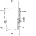
また、下流側接続部641と上流側接続部661との接続構造の詳細が図4の断面図に示されている。その図4は、図3のIV部分に相当する部分を拡大した図であって、下流側接続部641と上流側接続部661との接続構造を示した断面図である。図3は、下流ダクト部材64が上流ダクト部材66へ接続される前の状態を表しているが、図4は、下流ダクト部材64が上流ダクト部材66へ接続された後の状態を表している。
図4に示すように、下流側接続部641および上流側接続部661は何れも、筒形状たとえば円筒形状を成している。そして、筒形状の下流側接続部641は下流ダクト通路64aを介して後側開口部62へ連通している。言い換えれば、下流側接続部641は下流側接続部641の内側に空気通路を形成し、その空気通路が下流ダクト通路64aを介して後側開口部62(図1参照)へ連通している。
その一方で、筒形状の上流側接続部661は、上流ダクト通路66aを介してシュラウド50の通風孔50b(図2参照)へ連通している。言い換えれば、上流側接続部661は上流側接続部661の内側に空気通路を形成し、その空気通路が上流ダクト通路66aを介してシュラウド50の通風孔50bへ連通している。
更に、下流側接続部641の太さDLと上流側接続部661の太さDUとが互いに異なっている。要するに、両方の接続部641、661の筒のサイズが互いに異なっている。そして、下流側接続部641と上流側接続部661とのうちの一方の接続部が他方の接続部内に挿入されている。本実施形態では、下流側接続部641は上流側接続部661よりも細く形成されており、下流側接続部641が上流側接続部661内に挿入されている。従って、下流側接続部641の太さDLとは具体的には下流側接続部641の外径であり、上流側接続部661の太さDUとは具体的には上流側接続部661の内径である。
このように下流側接続部641が上流側接続部661内に挿入されることによって、下流ダクト部材64は、シュラウド50に対し上流ダクト部材66を介して接続されている。そして、下流側接続部641は上流側接続部661の径方向内側に重ねて設けられている。例えば本実施形態では、下流側接続部641は、上流側接続部661内へ車両上下方向DR3(図2参照)に挿入されている。
そして、下流側接続部641および上流側接続部661はそれぞれ、シュラウド50から下流ダクト部材64を取り外すことができるように構成されている。詳細に言えば、下流側接続部641および上流側接続部661はそれぞれ、シュラウド50に固定された上流ダクト部材66から下流ダクト部材64を取り外すことができるように構成されている。
図1および図2に戻り、エキゾーストマニホールド18は、走行用エンジン16から排気ガスを排出する排気管において、走行用エンジン16に接続される複数の排気流路を1つにまとめる多岐管である。エキゾーストマニホールド18は、エンジンルーム14のうち、走行用エンジン16に対して車両後方に配置されている。
また、本実施形態では、エンジンルーム14のうち走行用エンジン16に対する車両後方には、エキゾーストマニホールド18以外にターボチャージャー用タービンや触媒装置が配置されている。触媒装置は、走行用エンジン16から吹き出される排ガス中の有害成分を還元・酸化によって浄化する装置である。ターボチャージャーは、走行用エンジン16から吹き出される排ガスの内部エネルギーからタービンにより回転エネルギーを取りだし、この回転エネルギーにより圧縮器を作動させて圧縮空気を生成して走行用エンジン16の吸気口に供給する装置である。ターボチャージャー用タービンは、排ガスの内部エネルギーから回転エネルギーを取り出す装置である。
ところで、自動車12が高速で走行しているときには、自動車12の走行に伴って、自動車12の車両前方からエンジンルーム開口部2、コンデンサ20、ラジエータ30、および電動ファン40を通過する車両走行風としての空気流が発生する。
このため、自動車12の車両前方からエンジンルーム開口部2、コンデンサ20、およびラジエータ30を通過した車両走行風としての空気流の一部が、シュラウド50の通風孔50bから前側開口部61を通して導風ダクト60のダクト内流路60aに導入される。そして、そのダクト内流路60aに導入された空気流は、導風ダクト60の後側開口部62からエキゾーストマニホールド18側へ吹き出される。このため、エンジンルーム14内のエンジン後方空間に配置されたエキゾーストマニホールド18、触媒装置、およびターボチャージャー用タービンを、導風ダクト60に導かれ後側開口部62から吹き出される空気によって冷却することができる。そのエンジン後方空間とは、エンジンルーム14内のうち走行用エンジン16に対する車両後方の空間である。
また、このようにエキゾーストマニホールド18、触媒装置、およびターボチャージャー用タービンを冷却した空気流は、エキゾーストマニホールド18の床下側に流れる。このことにより、エンジンルーム開口部2、コンデンサ20、ラジエータ30、導風ダクト60、およびエキゾーストマニホールド18の周辺を通過して自動車12の床下側に流れる空気流が発生する。
また、自動車12の車両前後方向前側からエンジンルーム開口部2を通して導入流路50a内に導入された空気流のうち、導風ダクト60に流入された空気流以外の残りの空気流は、電動ファン40に吸い込まれる。この電動ファン40によって吸い込まれた残りの空気は、走行用エンジン16周辺を通過して床下側に流れる。このため、導入流路50aから電動ファン40を通過して走行用エンジン16側に流れる空気流により走行用エンジン16を冷却することになる。
以上説明した本実施形態によれば、エンジンルーム14内のうちエンジン後方空間を上述のように冷却することが可能である。すなわち、そのエンジン後方空間に配置されたエキゾーストマニホールド18、触媒装置、およびターボチャージャー用タービンを冷却することが可能である。このため例えば、エキゾーストマニホールド18、触媒装置、ターボチャージャー用タービン、およびその周辺部品に熱害が生じることを避けることができる。
そして、導風ダクト60はその導風ダクト60の一部として下流ダクト部材64を含み、その下流ダクト部材64は、シュラウド50から下流ダクト部材64を取り外すことができるように構成された下流側接続部641を後側開口部62側とは反対側に有している。従って、シュラウド50をエンジンルーム14内から取り外さなくても、下流ダクト部材64をシュラウド50から分離してエンジンルーム14内から取り外すことが可能である。これにより、走行用エンジン16に関わるサービス性が導風ダクト60に起因して悪化することを抑えることが可能である。例えば、作業者は、走行用エンジン16またはその周辺機器に関わる作業を行う際には、冷却モジュール10のうち走行用エンジン16の上側にある下流ダクト部材64だけを取り外して作業をすることができる。
また、シュラウド50から下流ダクト部材64を取り外すことが可能であるので、シュラウド50と下流ダクト部材64と上流ダクト部材66とを同時にエンジンルーム14内に取り付ける必要がない。従って、導風ダクト60のエンジンルーム14内へ取り付ける際の組付け性を良好に確保することが可能である。例えば、作業者は、シュラウド50とそのシュラウド50に固定された上流ダクト部材66とをエンジンルーム14内に取り付けた後に下流ダクト部材64を取り付けることが可能である。
また、走行用エンジン16に固定されている下流ダクト部材64と、シュラウド50を介して車両ボデー6に固定されている上流ダクト部材66とが別々の部材とされている。そのため、車両ボデー6の振動が伝わる上流ダクト部材66と走行用エンジン16の振動が伝わる下流ダクト部材64との間で振動位相差を吸収することができる。従って、シュラウド50および導風ダクト60の振動耐久性を良好に確保することが可能である。
また、本実施形態によれば、下流側接続部641および上流側接続部661は何れも筒形状を成し、上流側接続部661は上流ダクト通路66aを通ってシュラウド50の通風孔50bへ連通している。そして、下流側接続部641が上流側接続部661内に挿入されており、これによって、下流ダクト部材64は、シュラウド50に対し上流ダクト部材66を介して接続されている。従って、下流ダクト部材64と上流ダクト部材66とを簡素な構造によって通風可能に接続することができる。
また、本実施形態によれば、下流ダクト部材64は上流ダクト部材66を介しシュラウド50に対して接続されている。従って、その下流ダクト部材64と上流ダクト部材66との接続箇所を、シュラウド50の配置に拘束されずに所望の位置にレイアウトすることが容易である。例えば、そのダクト部材64、66同士の接続箇所を、接続作業が容易となる位置にレイアウトできる。
また、本実施形態では、導風ダクト60の前側開口部61は、シュラウド50の通風孔50bにてそのシュラウド50に接続されている。このため、自動車12の高速走行時にてエンジンルーム開口部2を介してラジエータ30を通過する空気流の抵抗を低減することができる。例えば、ラジエータ30を通過する送風量としては、シュラウド50にラム圧孔を設けた従来の電動ファン40を用いた場合と同等の送風量を得ることができる。その結果として、ラジエータ30を冷却する冷却能力を向上することができる。
(第2実施形態)
次に、第2実施形態について説明する。本実施形態では、前述の第1実施形態と異なる点を主として説明する。また、前述の実施形態と同一または均等な部分については省略または簡略化して説明する。後述の第3実施形態以降でも同様である。
次に、第2実施形態について説明する。本実施形態では、前述の第1実施形態と異なる点を主として説明する。また、前述の実施形態と同一または均等な部分については省略または簡略化して説明する。後述の第3実施形態以降でも同様である。
図5は、本実施形態の冷却モジュール10において第1実施形態と異なる点を示した図であって、図4と同様に下流側接続部641と上流側接続部661との接続構造を示した断面図である。この図5に示すように、本実施形態では導風ダクト60がシール材68を有している。この点が第1実施形態とは異なる。
具体的に導風ダクト60のシール材68は、ゴムまたは発泡ウレタン等の弾性体で構成されている。そして、シール材68は、下流側接続部641と上流側接続部661との間に形成される径方向隙間の全周にわたって設けられており、両方の接続部641、661によって径方向に圧縮されている。これにより、シール材68は、下流側接続部641と上流側接続部661との間の径方向隙間を塞いでいる。
本実施形態では、前述の第1実施形態と共通の構成から奏される効果を第1実施形態と同様に得ることができる。また、本実施形態によれば、導風ダクト60のシール材68が下流側接続部641と上流側接続部661との間の径方向隙間を塞いでいるので、下流ダクト部材64と上流ダクト部材66との接続箇所において空気漏れを防止することが可能である。
(第3実施形態)
次に、第3実施形態について説明する。本実施形態では、前述の第1実施形態と異なる点を主として説明する。
次に、第3実施形態について説明する。本実施形態では、前述の第1実施形態と異なる点を主として説明する。
下流ダクト部材64は、上述した図3の矢印AR1に示すように、走行用エンジン16に対して上側から組み付けられるが、本実施形態では、下流ダクト部材64はエンジンカバー72の一部分を構成している。すなわち、下流ダクト部材64はエンジンカバー72の一部分として活用される。この点が第1実施形態とは異なる。
本実施形態のエンジンカバー72は例えば樹脂製であり、下流ダクト部材64を含んで一体成形されている。エンジンカバー72は、エンジンルーム14内に配置され、走行用エンジン16の上側のうち少なくとも一部を覆っている。このエンジンカバー72は、例えば走行用エンジン16から発生するエンジン音を防音する役割等を果たす。
そして、エンジンカバー72は、走行用エンジン16に対してボルト締結等によって固定されている。要するに、エンジンカバー72は、走行用エンジン16に対し取外し可能に固定されている。従って、エンジンカバー72に含まれる下流ダクト部材64も走行用エンジン16に対して取外し可能である。
本実施形態では、前述の第1実施形態と共通の構成から奏される効果を第1実施形態と同様に得ることができる。また、本実施形態によれば、下流ダクト部材64はエンジンカバー72の一部分を構成しているので、エンジンカバー72を走行用エンジン16から取り外す作業において下流ダクト部材64も併せて取り外すことが可能である。
なお、本実施形態は第1実施形態に基づいた変形例であるが、本実施形態を前述の第2実施形態と組み合わせることも可能である。
(第4実施形態)
次に、第4実施形態について説明する。本実施形態では、前述の第1実施形態と異なる点を主として説明する。
次に、第4実施形態について説明する。本実施形態では、前述の第1実施形態と異なる点を主として説明する。
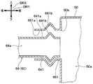
図6は、本実施形態の冷却モジュール10において第1実施形態と異なる点を示した図であって、下流側接続部641と上流側接続部661との接続構造を示した断面図である。本実施形態では、導風ダクト60は、第1実施形態における2本のダクト部材64、66のうち第1ダクト部材としての下流ダクト部材64に相当するダクト部材64だけを有し、上流ダクト部材66に相当する部材を有していない。そのため、第2接続部としての上流側接続部661は、図6に示すようにシュラウド50に直接設けられる。そして、ダクト部材64は、シュラウド50に直接接続されている。これらの点が第1実施形態とは異なる。
具体的には図6に示すように、下流側接続部641および上流側接続部661は何れも筒形状を成しており、下流側接続部641は上流側接続部661内に挿入されている。そして、上流側接続部661は、下流側接続部641に対して対向する内周側面661aと、その内周側面661aに形成され内周側面661aから凹んだ凹部661bとを有している。その一方で、下流側接続部641は、上記の内周側面661aに対して対向する外周側面641aと、その外周側面641aから突出し凹部661bに係合する凸部641bとを有している。
この凸部641bおよび凹部661bは下流側接続部641および上流側接続部661の全周にわたって形成されており、その全周にわたって凸部641bは凹部661bに嵌り込んで係合している。
本実施形態では、前述の第1実施形態と共通の構成から奏される効果を第1実施形態と同様に得ることができる。
また、本実施形態によれば、下流側接続部641の凸部641bは上流側接続部661の凹部661bに係合している。従って、ダクト部材64の下流側接続部641がシュラウド50の上流側接続部661から外れ難いように、下流側接続部641を上流側接続部661に接続することが可能である。
なお、本実施形態は第1実施形態に基づいた変形例であるが、本実施形態を前述の第2実施形態または第3実施形態と組み合わせることも可能である。
(第5実施形態)
次に、第5実施形態について説明する。本実施形態では、前述の第4実施形態と異なる点を主として説明する。
次に、第5実施形態について説明する。本実施形態では、前述の第4実施形態と異なる点を主として説明する。
図7は、本実施形態の冷却モジュール10において第4実施形態と異なる点を示した図であって、下流側接続部641と上流側接続部661との接続構造を示した断面図である。本実施形態では、下流側接続部641の凸部641bおよび上流側接続部661の凹部661b(図6参照)は設けられておらず、下流側接続部641と上流側接続部661とが永久磁石74の磁力を利用して接続されている。この点が第1実施形態とは異なる。
具体的には図7に示すように、下流側接続部641および上流側接続部661は何れも筒形状を成しており、上流側接続部661は下流側接続部641内に挿入されている。そして、上流側接続部661は、永久磁石74を上流側接続部661の基端部分に有している。その一方で、下流側接続部641は、その永久磁石74の磁力によって永久磁石74に引き寄せられる被吸引部材76を下流側接続部641の先端部分に有している。例えば上流側接続部661の永久磁石74はその磁力により、被吸引部材76を下流側接続部641および上流側接続部661の軸方向に引き寄せる。その被吸引部材76は、例えば上流側接続部661の永久磁石74と磁力によって引き合う鉄板または磁石等で構成されている。
従って本実施形態では、ダクト部材64は、下流側接続部641と上流側接続部661とが永久磁石74と被吸引部材76との間に生じる磁力を伴って接続されることで、シュラウド50に対して接続されている。これにより、下流側接続部641と上流側接続部661とが接続された状態を磁力によって容易に維持することが可能である。また、永久磁石74と被吸引部材76とが磁力で互いに密着するので、下流側接続部641と上流側接続部661との間に十分なシール性を確保することが可能である。
また、上流側接続部661は、上流側接続部661の軸方向において永久磁石74の磁力が被吸引部材76に及ぶ距離よりも長く下流側接続部641内へ挿入されている。これにより、振動等に起因して永久磁石74と被吸引部材76とが上流側接続部661の軸方向に多少離れても、下流側接続部641から上流側接続部661が脱落することを防止することが可能である。そして、その永久磁石74と被吸引部材76との位置関係をそれらが離れる前の状態に永久磁石74の磁力によって復元させることが可能である。
また、永久磁石74と被吸引部材76とは下流側接続部641および上流側接続部661の軸方向に突き当てられている。そして、その永久磁石74と被吸引部材76との一方が他方よりも、下流側接続部641および上流側接続部661の径方向に幅広く拡がって形成されている。本実施形態では、永久磁石74が被吸引部材76よりも径方向に幅広く拡がって形成されている。従って図8に示すように、下流側接続部641および上流側接続部661の一方が他方に対して径方向にずれたとしても、永久磁石74と被吸引部材76とが磁力によって密着した状態が維持される。これにより、下流側接続部641と上流側接続部661との間のシール性を保持することが可能である。
なお、本実施形態では、前述の第4実施形態と共通の構成から奏される効果を第4実施形態と同様に得ることができる。また、本実施形態は第4実施形態に基づいた変形例であるが、本実施形態を前述の第3実施形態と組み合わせることも可能である。
(第6実施形態)
次に、第6実施形態について説明する。本実施形態では、前述の第1実施形態と異なる点を主として説明する。
次に、第6実施形態について説明する。本実施形態では、前述の第1実施形態と異なる点を主として説明する。
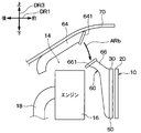
図9および図10は、本実施形態の冷却モジュール10において第1実施形態と異なる点を示した図であって、冷却モジュール10、走行用エンジン16、およびボンネット70等を車両幅方向DR2での右側から視た模式図である。図9は、ボンネット70が開いた状態を表し、図10は、ボンネット70が閉じた状態を表している。
図9および図10に示すように、本実施形態では下流ダクト部材64は走行用エンジン16には固定されておらずボンネット70に固定されている。この点が第1実施形態とは異なる。また、下流側接続部641および上流側接続部661の構成も第1実施形態とは異なる。
具体的に、下流ダクト部材64は、例えばボルト留め等によってボンネット70に対し一体的に固定されている。そして、そのボンネット70は、車両ボデー6に対しヒンジを介して連結されている。従って、ボンネット70はそのヒンジを中心として回動しつつ開閉動作をする。
下流側接続部641および上流側接続部661は、ゴム等の弾力性を有する材料で構成され、例えば内側を空気が通過するように環状に形成されている。そして、上流側接続部661は下流側接続部641に対して下側に配置されている。
そして、下流ダクト部材64はボンネット70と共に回動し、ボンネット70がエンジンルーム14の上部を開いている場合には、図9に示すように上流ダクト部材66およびシュラウド50から分離される。すなわち、その場合には、下流側接続部641も上流側接続部661から分離される。
図9に示すボンネット70が開いた状態から閉じる向きに回動すると、そのボンネット70の回動と共に下流側接続部641は矢印ARbのように移動して上流側接続部661へ近づく。
そして、下流ダクト部材64は、ボンネット70がエンジンルーム14の上部を閉じている場合には、図10に示すように、下流側接続部641と上流側接続部661とが互いに密着させられる。そして、下流ダクト通路64aと上流ダクト通路66a(図1参照)とが互いに連通する。すなわち、その場合には、下流ダクト部材64は、下流側接続部641と上流側接続部661とが互いに接続されることで、上流ダクト部材66を介しシュラウド50に対して接続される。この図10に示すようにボンネット70が閉じた状態では、下流側接続部641と上流側接続部661とが互いに密着させられているので、下流ダクト部材64と上流ダクト部材66との接続箇所におけるシール性が確保される。
なお、図10中の破線矢印は走行用エンジン16の排気の流れを示し、実線矢印は、車両前方から導風ダクト60に導入される冷却風の流れを示している。この図10の実線矢印のように、例えば車両走行中にはその冷却風が走行用エンジン16の後方にまで導かれ、エキゾーストマニホールド18が冷却される。
本実施形態では、前述の第1実施形態と共通の構成から奏される効果を第1実施形態と同様に得ることができる。
また、本実施形態によれば、下流ダクト部材64は、ボンネット70に固定されており、そのボンネット70と共に回動する。従って、作業者が走行用エンジン16またはその周辺機器に関わる作業を行う際に、下流ダクト部材64を取り外す必要がないというメリットがある。
(第7実施形態)
次に、第7実施形態について説明する。本実施形態では、前述の第1実施形態と異なる点を主として説明する。
次に、第7実施形態について説明する。本実施形態では、前述の第1実施形態と異なる点を主として説明する。
図11は、本実施形態の冷却モジュール10において第1実施形態と異なる点を示した図であって、下流側接続部641および上流側接続部661をそれらの軸方向に直交する断面で切断した断面図である。この図11に示すように、本実施形態の冷却モジュール10は、下流側接続部641を上流側接続部661に係止する係止構造を備えている。この点が第1実施形態とは異なる。
具体的には図11に示すように、下流側接続部641および上流側接続部661は何れも筒形状を成しており、下流側接続部641は上流側接続部661内に挿入されている。そして、下流側接続部641は、上流側接続部661に対して対向する外周側面641aと、その外周側面641aから延びて紐状を成す紐部78とを有している。この紐部78は可撓性を有し、紐部78の途中で局所的に膨らんだ複数の瘤部781、782を含んで一体成形されている。本実施形態において紐部78は複数本、具体的には2本設けられているが、この紐部78の本数および配置は図11に示すものには限定されない。
紐部78が有する瘤部781、782は例えばゴム等の弾力性を有する材料で構成されている。瘤部781、782は図12に示すように球形状に形成され、且つ、瘤部781、782の内部は中空とされている。これにより、瘤部781、782は外力が加えられることにより変形しやすくなっている。例えば、図13に示すように紐部78に外力F1が加えられて紐部78が引っ張られた場合には、瘤部781が紐部78の長手方向に延びると共に細く変形する。従って、瘤部781、782を図13のように変形させることで、瘤部781、782の外径よりも小径の孔に瘤部781、782を通すことが可能である。図12は、紐部78単体を表した断面図であり、図13は、その図12と同じ断面において、外力F1で瘤部781を変形させた状態を示した断面図である。
また、図11に示すように、上流側接続部661には、その上流側接続部661を板厚方向に貫通する挿通孔78aが形成されている。この挿通孔78aは紐部78の数と同数設けられており、瘤部781、782の外径よりも小さく形成されている。
そして、図11のXIV-XIV断面図である図14に示すように、上流側接続部661の複数の挿通孔78aには、下流側接続部641の複数本の紐部78がそれぞれ挿通されている。それと共に、挿通孔78aは、紐部78の接続端783と瘤部781との間に配置されている。すなわち、紐部78が有する複数の瘤部781、782のうち少なくとも1つの瘤部781が上流側接続部661よりも外側に配置されている。紐部78の接続端783は、その紐部78のうち下流側接続部641の外周側面641aに接続されている端部である。
例えば下流側接続部641と上流側接続部661との位置関係は通常は図14に示す通りであるが、図15に示すように外力F2が下流側接続部641を上流側接続部661から抜き去る方向に加えられることがある。そのように外力F2が加えられた場合には、図15に示すように下流側接続部641は上流側接続部661に対して或る程度はずれるものの、紐部78が有する瘤部781によって係止される。従って、下流ダクト部材64(図1参照)が上流ダクト部材66から脱落することを防止することが可能である。
なお、本実施形態では、前述の第1実施形態と共通の構成から奏される効果を第1実施形態と同様に得ることができる。また、本実施形態は第1実施形態に基づいた変形例であるが、本実施形態を前述の第2実施形態または第3実施形態と組み合わせることも可能である。
(他の実施形態)
(1)上述の第1実施形態において、導風ダクト60は2本のダクト部材64、66から構成されているが、これは一例である。例えば、導風ダクト60は、その2本のダクト部材64、66のうち下流ダクト部材64に相当するダクト部材すなわち第1ダクト部材だけを有し、その第1ダクト部材がシュラウド50に直接接続されていても差し支えない。要するに、上記第1ダクト部材は導風ダクト60の一部を構成していてもよいし、導風ダクト60の全部を構成していてもよいということである。そのように第1ダクト部材が導風ダクト60の全部を構成していている場合には、上流ダクト部材66が無いので、上流側接続部661に相当する接続部すなわち第2接続部はシュラウド50に直接設けられる。このことは、第2、第3、第6、および第7実施形態でも同様である。
(1)上述の第1実施形態において、導風ダクト60は2本のダクト部材64、66から構成されているが、これは一例である。例えば、導風ダクト60は、その2本のダクト部材64、66のうち下流ダクト部材64に相当するダクト部材すなわち第1ダクト部材だけを有し、その第1ダクト部材がシュラウド50に直接接続されていても差し支えない。要するに、上記第1ダクト部材は導風ダクト60の一部を構成していてもよいし、導風ダクト60の全部を構成していてもよいということである。そのように第1ダクト部材が導風ダクト60の全部を構成していている場合には、上流ダクト部材66が無いので、上流側接続部661に相当する接続部すなわち第2接続部はシュラウド50に直接設けられる。このことは、第2、第3、第6、および第7実施形態でも同様である。
(2)上述の第4実施形態において、導風ダクト60は、第1実施形態の上流ダクト部材66に相当する部材を有していないが、これは一例である。例えば、導風ダクト60は、第1実施形態と同様にその上流ダクト部材66を有すると共に、ダクト部材64を、その上流ダクト部材66に接続される下流ダクト部材64として有していても差し支えない。このことは、第5実施形態でも同様である。
(3)上述の各実施形態において、エンジンルーム開口部2は自動車12のフロントグリル4に形成されているが、それに限らず例えば、自動車12のフロントバンパーの下側前面に開口して形成されていても差し支えない。
(4)上述の第1実施形態において、筒状の下流側接続部641は、図4に示すように筒状の上流側接続部661内に挿入されているが、逆に図16に示すように、上流側接続部661が下流側接続部641内に挿入されていても差し支えない。この図16のように挿入されるとすれば、下流側接続部641の太さDLは具体的には下流側接続部641の内径を表し、上流側接続部661の太さDUは具体的には上流側接続部661の外径を表す。
更に、図17に示すように、上流側接続部661が下流側接続部641内に挿入された接続状態において、第2実施形態と同様に、下流側接続部641と上流側接続部661との間の径方向隙間がシール材68によって塞がれていても差し支えない。
(5)上述の第4実施形態において、下流側接続部641および上流側接続部661の全周にわたって凸部641bは凹部661bに嵌り込んで係合しているが、その全周のうちの一部分にて凹部661bに嵌り込んで係合しているだけであっても差し支えない。例えば図18に示すように、下流側接続部641が上流側接続部661の内側において下側に偏って位置した場合には、凸部641bおよび凹部661bの下側部分が互いに係合すればよい。逆に、図19に示すように下流側接続部641が上流側接続部661の内側において上側に偏って位置した場合には、凸部641bおよび凹部661bの上側部分が互いに係合すればよい。
要するに、下流側接続部641が上流側接続部661に対し車両幅方向DR2(図1参照)または車両上下方向DR3(図2参照)に振動した場合に、下流側接続部641および上流側接続部661の全周のうちの何れかの箇所で、凸部641bと凹部661bとが互いに係合すればよい。
(6)上述の第4実施形態において、下流側接続部641は、図6に示すように上流側接続部661内に挿入されているが、これは一例である。例えば、これとは逆に、上流側接続部661が下流側接続部641内に挿入されていても差し支えない。その場合には例えば、下流側接続部641が凹部661bを有し、上流側接続部661が凸部641bを有することとなる。
(7)上述の第4実施形態では図6に示すように、上流側接続部661が凹部661bを有し、上流側接続部661の内側に挿入された下流側接続部641が凸部641bを有しているが、これは一例である。例えば、これとは逆に図20に示すように、上流側接続部661が凸部661cを有し、下流側接続部641が凹部641cを有していても差し支えない。
その図20では、下流側接続部641は、その下流側接続部641の外周側面641aに形成され外周側面641aから凹んだ凹部641cを有している。そして、上流側接続部661は、その上流側接続部661の内周側面661aから突出し凹部641cに係合する凸部661cを有している。
(8)上述の第5実施形態において、上流側接続部661は永久磁石74を有し、下流側接続部641は被吸引部材76を有しているが、逆に、上流側接続部661が被吸引部材76を有し、下流側接続部641が永久磁石74を有していても差し支えない。
(9)上述の第7実施形態では図11に示すように、下流側接続部641は紐部78を有し、下流側接続部641の外側に配置された上流側接続部661には挿通孔78aが形成されているが、これは一例である。例えば、これとは逆に、下流側接続部641に挿通孔78aが形成され、上流側接続部661が紐部78を有していてもよい。そのようにしたとすれば、上流側接続部661は、その上流側接続部661の内周側面661aから延びる紐部78を有し、紐部78の接続端783はその内周側面661aに接続される。そして、下流側接続部641の挿通孔78aは、紐部78の接続端783と瘤部781との間に配置される。
(10)上述の各実施形態において、冷却モジュール10は、エンジン冷却用熱交換器としてラジエータ30を有しているが、これに替えて、熱媒体としてのエンジンオイルを冷却するオイルクーラをエンジン冷却用熱交換器として有していても差し支えない。
(11)上述の各実施形態において、導風ダクト60は、エンジンルーム14内において走行用エンジン16の上側に配置されているが、走行用エンジン16の上側以外の位置に配置されていても構わない。
(12)上述の各実施形態において、エンジンルーム開口部2はラジエータ30に対する車両前方に設けられているが、例えば、そのエンジンルーム開口部2は、ラジエータ30に対して車両幅方向DR2にオフセットされた位置に設けられていても差し支えない。
(13)上述の各実施形態において、エキゾーストマニホールド18は、エンジンルーム14のうち、走行用エンジン16に対して車両後方に配置されているが、走行用エンジン16に対して車両後方以外の位置に配置されていても構わない。
(14)上述の各実施形態において、電動ファン40は、例えば軸流式の送風機であると説明されているが、軸流式以外の送風機、例えば遠心式の送風機であっても差し支えない。
(15)上述の各実施形態において、コンデンサ20、ラジエータ30、および電動ファン40は、車両前方からコンデンサ20、ラジエータ30、電動ファン40の順に並んで配置されているが、その並び順に限定されなくてよい。
なお、本開示は上記した実施形態に限定されるものではない。本開示は、様々な変形例や均等範囲内の変形をも包含する。また、上記各実施形態は、互いに無関係なものではなく、組み合わせが明らかに不可な場合を除き、適宜組み合わせが可能である。また、上記各実施形態において、実施形態を構成する要素は、特に必須であると明示した場合および原理的に明らかに必須であると考えられる場合等を除き、必ずしも必須のものではないことは言うまでもない。また、上記各実施形態において、実施形態の構成要素の個数、数値、量、範囲等の数値が言及されている場合、特に必須であると明示した場合および原理的に明らかに特定の数に限定される場合等を除き、その特定の数に限定されるものではない。また、上記各実施形態において、構成要素等の材質、形状、位置関係等に言及するときは、特に明示した場合および原理的に特定の材質、形状、位置関係等に限定される場合等を除き、その材質、形状、位置関係等に限定されるものではない。
Claims (13)
- 走行用エンジン(16)が配置されるエンジンルーム(14)の車両前方にて開口したエンジンルーム開口部(2)から前記エンジンルーム内へ空気が流入する自動車(12)に適用される導風ユニットであって、
空調装置の放熱器(20)と前記走行用エンジンを冷却するためのエンジン冷却用熱交換器(30)と送風機(40)とが固定され、前記エンジンルーム開口部を経て前記放熱器および前記エンジン冷却用熱交換器を通過する空気を案内し、通風孔(50b)が形成されたシュラウド(50)と、
前記通風孔にて前記シュラウドに接続され該通風孔を通して開口する第1開口部(61)と前記エンジンルーム内のうち前記走行用エンジンに対する車両後方に開口する第2開口部(62)とを有し、前記第1開口部と前記第2開口部との間に空気を流す導風ダクト(60)とを備え、
該導風ダクトは、該導風ダクトの少なくとも一部を構成し且つ前記第2開口部を有すると共に前記通風孔からの空気を前記第2開口部へ流す第1ダクト通路(64a)を形成する第1ダクト部材(64)を含み、
該第1ダクト部材は、前記シュラウドから前記第1ダクト部材を取り外すことができるように構成された第1接続部(641)を前記第2開口部側とは反対側に有している導風ユニット。 - 筒形状を成して前記通風孔へ連通し且つ前記シュラウドに対して固定された第2接続部(661)を備え、
前記第1接続部は筒形状を成し、
前記第1ダクト部材は、前記第1接続部と前記第2接続部とのうちの一方の接続部が他方の接続部内に挿入されることで、前記シュラウドに対して接続される請求項1に記載の導風ユニット。 - 前記導風ダクトは、前記第1接続部と前記第2接続部との間に形成される隙間を塞ぐシール材(68)を有している請求項2に記載の導風ユニット。
- 前記一方の接続部は、前記他方の接続部の径方向内側に重ねて設けられる請求項2または3に記載の導風ユニット。
- 前記一方の接続部は、前記他方の接続部に対して対向する外周側面(641a)と、該外周側面に形成され該外周側面から凹んだ凹部(641c)とを有し、
前記他方の接続部は、前記外周側面に対して対向する内周側面(661a)と、該内周側面から突出し前記凹部に係合する凸部(661c)とを有している請求項2ないし4のいずれか1つに記載の導風ユニット。 - 前記他方の接続部は、前記一方の接続部に対して対向する内周側面(661a)と、該内周側面に形成され該内周側面から凹んだ凹部(661b)とを有し、
前記一方の接続部は、前記内周側面に対して対向する外周側面(641a)と、該外周側面から突出し前記凹部に係合する凸部(641b)とを有している請求項2ないし4のいずれか1つに記載の導風ユニット。 - 前記一方の接続部は、前記他方の接続部に対して対向する外周側面(641a)と、該外周側面から延びて紐状を成すと共に、局所的に膨らんだ瘤部(781)を含んで構成された紐部(78)とを有し、
前記他方の接続部には、前記紐部が挿通されると共に、前記紐部のうち前記外周側面に接続されている接続端(783)と前記瘤部との間に配置される挿通孔(78a)が形成されており、
該挿通孔は、前記瘤部の外径よりも小さく形成されている請求項2ないし4のいずれか1つに記載の導風ユニット。 - 前記他方の接続部は、前記一方の接続部に対して対向する内周側面(661a)と、該内周側面から延びて紐状を成すと共に、局所的に膨らんだ瘤部(781)を含んで構成された紐部(78)とを有し、
前記一方の接続部には、前記紐部が挿通されると共に、前記紐部のうち前記内周側面に接続されている接続端(783)と前記瘤部との間に配置される挿通孔(78a)が形成されており、
該挿通孔は、前記瘤部の外形よりも小さく形成されている請求項2ないし4のいずれか1つに記載の導風ユニット。 - 前記通風孔へ連通する空気通路を形成し前記シュラウドに対して固定された第2接続部(661)を備え、
前記第1接続部と前記第2接続部とのうちの一方の接続部は永久磁石(74)を含んで構成され、他方の接続部は、前記永久磁石の磁力によって該永久磁石に引き寄せられる被吸引部材(76)を含んで構成され、
前記第1ダクト部材は、前記第1接続部と前記第2接続部とが前記永久磁石と前記被吸引部材との間に生じる磁力を伴って接続されることで、前記シュラウドに対して接続される請求項1に記載の導風ユニット。 - 前記通風孔へ連通する空気通路を形成し前記シュラウドに対して固定され、前記第1接続部に対して下側に配置される第2接続部(661)を備え、
前記第1ダクト部材は、
前記エンジンルームの上部を形成し開閉可能なボンネット(70)に固定され、
該ボンネットが前記エンジンルームの上部を閉じている場合には、前記第1接続部と前記第2接続部とが接続されることで前記シュラウドに対して接続される一方で、前記ボンネットが前記エンジンルームの上部を開いている場合には、前記シュラウドから分離される請求項1に記載の導風ユニット。 - 前記第1ダクト部材は、前記エンジンルーム内に配置され前記走行用エンジンの上側のうち少なくとも一部を覆うエンジンカバー(72)の一部分を構成し、
該エンジンカバーは、前記走行用エンジンに対し取外し可能に固定されている請求項2ないし9のいずれか1つに記載の導風ユニット。 - 前記導風ダクトは、前記第1ダクト部材と前記シュラウドとの間に介装され前記通風孔からの空気を前記第1ダクト通路へ流す第2ダクト通路(66a)を形成する第2ダクト部材(66)を含み、
前記第2ダクト部材は、前記第2接続部を前記第1ダクト部材側に有し、
前記第1ダクト部材は、前記第2ダクト部材を介し前記シュラウドに対して接続される請求項2ないし11のいずれか1つに記載の導風ユニット。 - 請求項1ないし12のいずれか1つに記載の導風ユニット(50、60)と、前記エンジン冷却用熱交換器と、前記送風機と、前記放熱器とを備えた冷却モジュール。
Applications Claiming Priority (2)
| Application Number | Priority Date | Filing Date | Title |
|---|---|---|---|
| JP2015147751A JP2018144501A (ja) | 2015-07-27 | 2015-07-27 | 導風ユニットおよび冷却モジュール |
| JP2015-147751 | 2015-07-27 |
Publications (1)
| Publication Number | Publication Date |
|---|---|
| WO2017018296A1 true WO2017018296A1 (ja) | 2017-02-02 |
Family
ID=57884682
Family Applications (1)
| Application Number | Title | Priority Date | Filing Date |
|---|---|---|---|
| PCT/JP2016/071286 Ceased WO2017018296A1 (ja) | 2015-07-27 | 2016-07-20 | 導風ユニットおよび冷却モジュール |
Country Status (2)
| Country | Link |
|---|---|
| JP (1) | JP2018144501A (ja) |
| WO (1) | WO2017018296A1 (ja) |
Citations (3)
| Publication number | Priority date | Publication date | Assignee | Title |
|---|---|---|---|---|
| JPS60110013U (ja) * | 1983-12-28 | 1985-07-26 | 愛知機械工業株式会社 | 内燃機関室の冷却構造 |
| JPS60134855U (ja) * | 1984-02-17 | 1985-09-07 | 愛知機械工業株式会社 | 気化器の冷却機構 |
| JP2007055274A (ja) * | 2005-08-22 | 2007-03-08 | Mazda Motor Corp | 車体前部構造 |
-
2015
- 2015-07-27 JP JP2015147751A patent/JP2018144501A/ja active Pending
-
2016
- 2016-07-20 WO PCT/JP2016/071286 patent/WO2017018296A1/ja not_active Ceased
Patent Citations (3)
| Publication number | Priority date | Publication date | Assignee | Title |
|---|---|---|---|---|
| JPS60110013U (ja) * | 1983-12-28 | 1985-07-26 | 愛知機械工業株式会社 | 内燃機関室の冷却構造 |
| JPS60134855U (ja) * | 1984-02-17 | 1985-09-07 | 愛知機械工業株式会社 | 気化器の冷却機構 |
| JP2007055274A (ja) * | 2005-08-22 | 2007-03-08 | Mazda Motor Corp | 車体前部構造 |
Also Published As
| Publication number | Publication date |
|---|---|
| JP2018144501A (ja) | 2018-09-20 |
Similar Documents
| Publication | Publication Date | Title |
|---|---|---|
| JP6447730B2 (ja) | 導風ユニットおよび冷却モジュール | |
| KR101189244B1 (ko) | 에어 덕트 | |
| JP4702014B2 (ja) | 車両の冷却装置 | |
| JP5655952B2 (ja) | 車両前部構造 | |
| US10179509B2 (en) | Cooling device and cooling module | |
| US10337394B2 (en) | Blower for vehicle | |
| CN103038081A (zh) | 车辆用冷却结构 | |
| KR101601409B1 (ko) | 차량 공조 시스템의 열 교환기를 위한 유체 관리 시스템 | |
| CN105317983B (zh) | 油冷却器 | |
| JP5192540B2 (ja) | 作業車両 | |
| KR200477303Y1 (ko) | 차량용 무시동 에어컨 | |
| WO2017030079A1 (ja) | 冷却装置 | |
| WO2017018296A1 (ja) | 導風ユニットおよび冷却モジュール | |
| WO2016092795A1 (ja) | 冷却装置、および冷却モジュール | |
| JP2012067721A (ja) | エンジン冷却装置 | |
| JP2001182097A (ja) | 建設機械のエンジン室 | |
| WO2018030378A1 (ja) | 車両の放熱器冷却システム、車両、及び車両の放熱器冷却方法 | |
| CN116601029A (zh) | 具有切向流涡轮机的用于电动或混合动力机动车辆的冷却模块 | |
| JP2006291537A (ja) | 作業機械の冷却構造 | |
| JP2007170241A (ja) | エンジンカバー構造 | |
| JP2006248476A (ja) | 自動車用空気調和装置 | |
| JP7795060B2 (ja) | モータジェネレータ冷却装置およびハイブリッドエンジン | |
| CN104245383A (zh) | 具有防止再循环特征的冷却系统 | |
| JPH10176533A (ja) | エンジン冷却装置 | |
| JP4735360B2 (ja) | 車両用冷却装置 |
Legal Events
| Date | Code | Title | Description |
|---|---|---|---|
| 121 | Ep: the epo has been informed by wipo that ep was designated in this application |
Ref document number: 16830401 Country of ref document: EP Kind code of ref document: A1 |
|
| NENP | Non-entry into the national phase |
Ref country code: DE |
|
| NENP | Non-entry into the national phase |
Ref country code: JP |
|
| 122 | Ep: pct application non-entry in european phase |
Ref document number: 16830401 Country of ref document: EP Kind code of ref document: A1 |