WO2017018113A1 - 対象物のハンドリングシミュレーション装置、対象物のハンドリングシミュレーションシステム、対象物のハンドリングをシミュレーションする方法、対象物の製造方法及び対象物のハンドリングシミュレーションプログラム - Google Patents
対象物のハンドリングシミュレーション装置、対象物のハンドリングシミュレーションシステム、対象物のハンドリングをシミュレーションする方法、対象物の製造方法及び対象物のハンドリングシミュレーションプログラム Download PDFInfo
- Publication number
- WO2017018113A1 WO2017018113A1 PCT/JP2016/069201 JP2016069201W WO2017018113A1 WO 2017018113 A1 WO2017018113 A1 WO 2017018113A1 JP 2016069201 W JP2016069201 W JP 2016069201W WO 2017018113 A1 WO2017018113 A1 WO 2017018113A1
- Authority
- WO
- WIPO (PCT)
- Prior art keywords
- handling
- data
- simulation
- movement
- subject
- Prior art date
Links
Images


Classifications
-
- G—PHYSICS
- G06—COMPUTING; CALCULATING OR COUNTING
- G06F—ELECTRIC DIGITAL DATA PROCESSING
- G06F30/00—Computer-aided design [CAD]
-
- G—PHYSICS
- G06—COMPUTING; CALCULATING OR COUNTING
- G06T—IMAGE DATA PROCESSING OR GENERATION, IN GENERAL
- G06T19/00—Manipulating 3D models or images for computer graphics
Definitions
- This invention relates to a technique for optimizing the handling of an object such as a wire harness.
- Non-Patent Documents 1 and 2 disclose techniques for designing a wire harness that is assembled to a vehicle or the like.
- Non-Patent Document 3 discloses a technique for designing a harness layout on a prototype of a stereoscopic image.
- Non-Patent Document 4 discloses a technique in which a main display is regarded as a work table, and a wiring operation of a harness is virtually performed on the main display.
- Non-Patent Document 5 discloses a method of expressing a linear object or the like by three variables representing bending and torsion and one variable representing expansion and contraction, thereby deriving a deformed shape of the linear object or the like. .
- This Non-Patent Document 5 describes that a system for generating a hand trajectory can be constructed when a linear object is handled by a manipulator or the like by simulating a deformed shape of the linear object or the like.
- Non-Patent Documents 1 to 5 Although a wire harness is expressed in a two-dimensional space or a three-dimensional space on a computer, no study is made regarding the handling properties of the wire harness.
- Non-Patent Document 5 discusses handling automation, but it is up to the study of statically stable shapes, such as the movement of objects and the possibility of potential movement such as the possibility of the wire rebounding. It does not disclose important points for handling optimization.
- an object of the present invention is to facilitate the optimization of the handling of an object.
- a first aspect is an object handling simulation apparatus, an object data receiving unit that receives object data including three-dimensional data of the object, and possible operation data of a handling subject
- a handling subject data receiving unit that accepts handling subject data
- an instruction data accepting unit that accepts handling instruction data of the object by the handling subject, the object data, the handling subject data, and the handling instruction data
- a simulation processing unit that simulates the movement of the object in the virtual three-dimensional space and the movement of the handling subject, and a simulation result of the movement of the object and the movement of the handling subject in the virtual three-dimensional space.
- the above And a evaluation value calculating unit for obtaining an evaluation value of the handling of elephants thereof.
- the second aspect is an object handling simulation apparatus according to the first aspect, wherein the simulation processing unit includes a physical operation unit that simulates the movement of the object according to a physical law.
- a 3rd aspect is the handling simulation apparatus of the target object which concerns on a 1st or 2nd aspect, Comprising:
- the said target object is a wire harness
- the said target object data reception part is a wire harness as said target object data.
- the object data including the three-dimensional data is received.
- a fifth aspect is an object handling simulation apparatus according to any one of the first to fourth aspects, wherein the instruction data receiving unit receives a plurality of types of handling instruction data, and the simulation processing unit includes: , For each of the plurality of types of handling instruction data, the movement of the object and the movement of the handling subject in a virtual three-dimensional space are simulated, and the evaluation value calculation unit includes the plurality of types of handling instructions Based on a simulation result for each of the data, an evaluation value of handling of the object is obtained.
- a sixth aspect is an object handling simulation apparatus according to any one of the first to fifth aspects, from a real space handling situation data acquisition unit that obtains handling situation data of the object in real space. Is reflected in at least one of the object data, the handling subject data, and the handling instruction data.
- the seventh aspect is an object handling simulation apparatus according to the sixth aspect, wherein the handling situation data includes incident situation data generated in a real space.
- An eighth aspect is an object handling simulation apparatus according to the sixth or seventh aspect, wherein the real space handling status data acquisition unit is configured to move the object in the real space and the movement of the handling subject. Is something to get.
- An object handling simulation system includes a plurality of object handling simulation apparatuses according to any one of the first to eighth aspects, wherein each of the plurality of object handling simulation apparatuses includes: The simulation is performed by changing at least one of the handling main body data and the handling instruction data.
- a tenth aspect is a method for simulating handling of an object by a computer, the step of receiving object data including three-dimensional data of the object, Based on the step of accepting handling subject data including operation data, the step of accepting handling instruction data of the object by the handling subject, the object data, the handling subject data, and the handling instruction data.
- a step of obtaining the evaluation value is a method for simulating handling of an object by a computer, the step of receiving object data including three-dimensional data of the object, Based on the step of accepting handling subject data including operation data, the step of accepting handling instruction data of the object by the handling subject, the object data, the handling subject data, and the handling instruction data.
- an object manufacturing method includes object data including three-dimensional data of an object, handling main data including possible operation data of the main object, and the target Based on the object handling instruction data, the computer simulates the movement of the object in the virtual three-dimensional space and the movement of the handling subject, and the movement of the object in the virtual three-dimensional space and the handling Determining a handling operation of the object based on a simulation result of the movement of the subject; obtaining a handling situation data of the object in a real space based on the determined handling operation; and Handling status of the object in space
- an object handling simulation program includes a computer, an object data receiving unit for receiving object data including three-dimensional data of the object, and a handling subject.
- a handling subject data receiving unit that accepts handling subject data including operation data
- an instruction data accepting unit that accepts handling instruction data of the object by the handling subject, the object data, the handling subject data, and the handling instruction data
- a simulation processing unit for simulating the movement of the object in the virtual three-dimensional space and the movement of the handling subject, and simulating the movement of the object and the movement of the handling subject in the virtual three-dimensional space. Based on the results so that they appear as an evaluation value calculation section for obtaining an evaluation value of the handling of the object.
- the object handling can be easily optimized.
- the simulation processing unit includes a physical calculation unit that simulates the movement of the object according to the physical law
- the object is not limited to a rigid body but also a flexible object. Can be simulated appropriately. Thereby, the evaluation value of the handling of the object can be obtained more appropriately, and the handling of the object can be optimized more appropriately.
- ⁇ Handling of wire harnesses is diverse, and the work order is also diverse.
- the optimization of the handling of the wire harness can be effectively performed.
- the simulation processing unit simulates the movement of the electric wire when arranging the electric wire on the wire harness assembly drawing board in the virtual three-dimensional space. It is possible to simulate the presence or absence of interference with the handling subject.
- suitable handling instruction data can be determined from a plurality of types of handling instruction data, and the handling of the object can be easily optimized.
- the sixth aspect it is possible to perform more optimal simulation by reflecting the handling status data in the real space, and to optimize the handling of the object more appropriately.
- the handling of the object can be optimized in consideration of the incident situation that is difficult to imagine in the initial simulation stage.
- handling situation data can be obtained by obtaining the movement of the object in the real space and the movement of the handling subject.
- At least one of the handling main body data and the handling instruction data can be made different to perform an efficient simulation.
- the tenth aspect it is possible to simulate the movement of the object in the virtual three-dimensional space and the movement of the handling subject, and obtain an evaluation value of the object handling based on the simulation result. Then, using the evaluation value as a clue, the object handling can be easily optimized.
- the movement of the object in the virtual three-dimensional space and the movement of the handling subject are simulated, and the handling of the object can be easily optimized based on the simulation result.
- more optimal simulation can be performed by reflecting the handling status data in the real space, and the object handling can be optimized more appropriately.
- the object handling can be easily optimized.
- FIG. 2 is a block diagram of a handling simulation device 50.
- FIG. It is a flowchart which shows the whole flow of the method of simulating the handling of a target object. It is explanatory drawing which shows the example of handling of the wire harness which concerns on 2nd Embodiment. It is explanatory drawing which shows the whole structure of the system containing a handling simulation apparatus. It is a block diagram of a handling simulation apparatus. It is a flowchart which shows the flow of the program for performing a handling simulation process.
- FIG. 1 is an explanatory diagram showing a process for simulating the handling of the object 10 and a process for reflecting the real space in the simulation
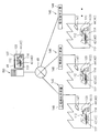
- FIG. 2 is an explanatory diagram showing the overall configuration of the system including the handling simulation apparatus.
- the handling of the object 10 is an operation of processing raw materials or combining various parts as necessary to manufacture industrial products or the like, or an industry prepared in advance. It is assumed that this is an operation for assembling a product or the like to another assembly object.
- the object 10 is assumed to be an original raw material or various parts and an industrial product obtained as a result of handling, and the handling includes the original raw material or various parts. Processing or combination work is assumed.
- the object 10 is an industrial product and an assembly object prepared in advance, and the handling is performed by grasping the industrial product prepared in advance to the assembly object. Installation work is assumed.
- the object 10 is handled by the handling subject 40 such as the operator 42 or the robot 44.
- the handling subject 40 may be only an operator (person), may be a robot alone, or may be a combination of both.
- a subject that handles the object 10 such as the worker 42 or the robot 44 may be collectively referred to as a handling subject 40.
- the robot may be a vertical articulated robot, an orthogonal robot, or a humanoid robot. Further, the robot may perform only movement according to prior teaching or the like, or may be a robot capable of autonomous movement.
- the handling simulation device 50 for the object 10 is constituted by a general computer.
- the computer may be configured by a single computer, or may be configured by a plurality of computers that perform processing in a distributed manner while being connected to each other.
- the handling simulation device 50 is operated by an engineer or the like who determines the work content, work order, etc. and creates a process design document when considering handling of the object 10.
- the handling simulation apparatus 50 simulates the movement of the object 10 and the movement of the handling subject 40 in the virtual three-dimensional space VR, and obtains an evaluation value for handling based on the simulation result. Obtaining an evaluation value of handling based on this simulation and the simulation result is performed a plurality of times by changing the contents of the movement of the handling subject 40. Based on each evaluation value, the most suitable movement of the handling subject 40 is determined, that is, the handling of the object 10 is optimized. As a result, a process design document (data) to be executed in the real space is created based on the work content and work order suitable for handling the object 10. This determination may be made manually in whole or in part by an engineer or the like based on each evaluation value.
- the object 10 is handled according to the process design document.
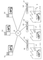
- the real space R (1), R (2), R (3),... Is assumed to be a production factory or the like.
- a real space handling situation data acquisition unit 46 for acquisition is provided.
- the real space handling situation data acquisition unit 46 performs, for example, the movement of the object 10 in the real space R (1), R (2), R (3)... And the three-dimensional movement of the handling subject 40 over time.
- the device is a motion capture device, for example, a motion capture device.
- the real space handling situation data acquisition unit 46 processes the stereo camera 47 and the video signal from the stereo camera 47 to acquire the three-dimensional movement of the object 10 and the handling subject 40 over time. It is shown as an apparatus including a factory side terminal device 48 including a three-dimensional processing unit.
- the communication network 49 may be wired or wireless, or may be a public communication network or a communication network using a dedicated line.
- the handling simulation apparatus 50 can acquire handling status data in each of the real spaces R (1), R (2), R (3).
- the handling simulation device 50 can simulate again the movement of the object 10 and the movement of the handling subject 40 in the virtual three-dimensional space VR by reflecting the handling situation data.
- the handling situation in the real space R (1), R (2), R (3)... Further suitable determination of the movement of the handling subject 40, that is, optimization of the handling of the object 10 Is made.
- the re-examined result is given to the real space R (1), R (2), R (3)... As a corrected process design document, and the real space R (1), R (2). , R (3)... Is handled based on the corrected process design document.
- the handling of the object 10 in the real space (1), R (2), R (3)... May be performed at a plurality of locations across a specific country or a plurality of countries. Moreover, it is preferable that the optimized result is transmitted to each of the real spaces (1), R (2), R (3)... As quickly as possible. Therefore, the system including the handling simulation device 50 may be realized by a cloud computing system.
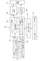
- FIG. 3 is a block diagram of the handling simulation apparatus 50.
- the handling simulation apparatus 50 includes an object data receiving unit 52, a handling subject data receiving unit 54, an instruction data receiving unit 56, a simulation processing unit 60, and an evaluation value calculating unit 68.
- the handling simulation apparatus 50 may be configured by a single computer, or may be configured by a plurality of computers that perform processing in a distributed manner while being connected to each other.
- the calculation operation of the handling simulation apparatus 50 is executed by a software program stored in advance (see the second embodiment).
- the object data receiving unit 52 is configured to be able to receive object data including three-dimensional data of the object 10 to be handled.
- object data when handling is a manufacturing operation, data on the product to be manufactured, the raw material of the manufacturer, data of parts, etc. are assumed, and when the handling is an assembly operation, Data on objects prepared in advance, data on objects to be assembled, and the like are assumed.
- shape data of the object 10 is defined in advance by a design drawing or the like.
- the object data including the three-dimensional data of the design drawing is received via the object data receiving unit 52 and stored in the storage device in the handling simulation apparatus 50.
- the handling subject data reception unit 54 is configured to accept handling subject data including possible operation data of the handling subject 40.
- the handling subject data is configured by data defining a general human body skeleton, degrees of freedom of each joint, a movable range, and the like.
- the handling subject 40 is the robot 44, it is constituted by data defining the length of each arm of the robot, the degree of freedom and the movable range of each joint, the direction of the movable axis, the movable range, and the like.
- the handling subject data is created based on a general human body model or specification data of a robot to be applied.
- the instruction data receiving unit 56 is configured to be able to receive handling instruction data of the object 10 by the handling subject 40. It can be said that the handling instruction data is data instructing the movement of the handling subject 40 that handles the object 10. When the handling of the object 10 is a manufacturing operation, the handling instruction data includes data for instructing the movement of the handling subject 40 so as to move the raw materials or parts that are the basis of the object 10. When the handling of the object 10 is an assembling operation, the handling instruction data includes data for instructing a procedure for assembling each part of the object 10 to the assembling object sequentially.
- One or more of the initial handling instruction data is created by the engineer or the like based on the empirical knowledge of the engineer or the inferred knowledge based on the three-letter original shape of the object 10 or the like.
- the object data reception unit 52, the handling subject data reception unit 54, and the instruction data reception unit 56 are communication interfaces that communicate with other computers and receive data stored in the other computers, such as a keyboard. It is assumed that it is a man-machine interface, a reader of a recording medium that reads a data recording medium created separately in advance, and the like.
- the simulation processing unit 60 simulates the movement of the object 10 and the movement of the handling subject 40 in the virtual three-dimensional space based on the object data, the handling subject data, and the handling instruction data. That is, the simulation processing unit 60 can generate the movement of the handling subject 40 in the virtual three-dimensional space based on the handling subject data and the handling instruction data. Further, the movement of the handling subject 40 in the virtual three-dimensional space indicates the handling content of the object 10 in the virtual three-dimensional space, that is, the movement. Therefore, the simulation processing unit 60 can simulate the movement of the target object 10 in the virtual three-dimensional space based on the handling main body data, the handling instruction data, and the target object data.
- the simulation processing unit 60 includes a handling main body operation simulation processing unit 62 and a physical calculation unit 64.
- the handling subject motion simulation processing unit 62 generates a motion of the handling subject 40 in the virtual three-dimensional space based on the handling subject data and the handling instruction data.
- the physical calculation unit 64 simulates the movement of the object 10 according to the physical laws (gravity, rigidity, etc.) based on the handling content of the object 10 determined by the handling main body data and the handling instruction data.
- the object 10 is not a rigid body but a flexible object such as a linear object or a film object
- mass data and rigidity data of each part are included in the object data.
- the movement of the object 10 can be simulated more realistically in consideration of the speed of movement of the handling subject 40 and the like.
- simulation result of the movement of the handling subject 40 and the simulation result of the movement of the object 10 are sequentially reflected to prevent one movement from interfering with the other movement.
- the simulation result is rendered by the rendering processing unit 66 so that the engineer can visually recognize the handling state by the display device 37 or the like.
- the evaluation value calculation unit 68 obtains an evaluation value for handling the object 10 based on the simulation result.
- the evaluation value is, for example, at least one of energy consumption determined based on the total time required to handle the object 10, the total movement time, the operation amount, the force required for handling, or the like, or the value thereof. It is represented by a value calculated by weighting.
- the handling instruction data can be changed by changing the contents of each work, changing the order of the contents of the handling, changing the subject of the handling (changing the number, changing the worker (person) to the robot or vice versa), etc. is there.
- handling instruction data suitable for handling the object 10 can be determined. This determination may be determined by the handling simulation device 50 based on the evaluation value, or may be determined by an engineer looking at the evaluation value.
- a work plan (data) is created by an engineer or the like.
- the real space handling situation data acquisition unit 46 of the real spaces R (1), R (2), R (3)... Is connected to the handling simulation device 50.
- the handling status data from the real space handling status data acquisition unit 46 is input to the reflection processing instruction unit 69.
- the reflection processing instruction unit 69 determines the contents to be reflected in the simulation process based on the handling status data from the real space handling status data acquisition unit 46. That is, when performing the simulation, not all situations in the real space are reflected. For example, the shape of the part provided may be different from the initially defined shape. In addition, when an operator performs a certain work content, a mistake is likely to occur or the movement becomes slow, and as a result, a handling time may be increased.
- the reflection processing instruction unit 69 determines the content to be reflected in the simulation processing based on the handling status data from the real space handling status data acquisition unit 46, and the handling status data of the target object 10 is converted into the target data, It is reflected in at least one of handling main body data and handling instruction data.
- the reflection processing instructing unit 69 moves the object 10 in the real space R (1), R (2), R (3)... Acquired by the real space handling situation data acquisition unit 46 and the subject of handling. 40 movements and their movements in the virtual three-dimensional space VR are compared, and each movement in the real space R (1), R (2), R (3)...
- the handling main body data or the handling instruction data is corrected in accordance with the above, and the simulation is instructed again. Thereby, similarly to the above, the optimum handling instruction data can be examined again.
- the reflection processing instruction unit 69 compares the shape of the target object 10 included in the handling status data from the real space handling status data acquisition unit 46 with the target data, so that the shape of the provided component can be determined.
- the object data is matched with the shape of the object 10 in the real space R (1), R (2), R (3). Instruct to correct and re-simulate. Thereby, similarly to the above, the optimum handling instruction data can be examined again.
- the reflection processing instruction unit 69 instructs to re-simulate based on incident situation data generated in the real space, although it is difficult to assume at the time of the initial simulation. Thereby, the handling of the object 10 can be optimized according to the situation of the real space R (1), R (2), R (3).
- the reflection processing instruction unit 69 statistically processes each real space handling situation data of the real spaces R (1), R (2), R (3)... By comparing the work with others, it is possible to specify efficient work contents, procedures, etc., and to instruct the simulation to be reflected again. As a result, some ingenuity or knowledge of the real spaces R (1), R (2), R (3)... Can be obtained from other real spaces R (1), R (2), R (3). It can be reflected in the work of.
- the processing in the reflection processing instruction unit 69 is preferably performed by analyzing various handling status data in the real space R (1), R (2), R (3). For this reason, when analyzing various handling situation data in the real spaces R (1), R (2), R (3)..., It is preferable to use a technique for analyzing so-called big data.
- FIG. 4 is a flowchart showing the overall flow of a method for simulating the handling of an object.
- step S1 the handling simulation device 50 simulates the movement of the handling subject 40 and the object 10 in the virtual three-dimensional space VR.
- Steps S1 and S2 are performed a plurality of times based on different handling instructions, and as a result, an optimized handling instruction is determined in the initial examination stage. Based on this handling instruction, process design is performed in step S3.
- step S4 the object 10 is handled based on the process design document in the real spaces R (1), R (2), R (3).
- step S6 the simulation in the virtual three-dimensional space VR is performed again, reflecting the handling situation in the real spaces R (1), R (2), R (3).
- step S7 an evaluation value is calculated based on the simulation result.
- step S8 the process is reviewed and the process design document is corrected as necessary.
- step S4 returns to step S4 and handling of the target object 10 based on a process design document is continued in real space R (1), R (2), R (3) ....
- the movement of the object 10 and the movement of the handling subject 40 in the virtual three-dimensional space VR are simulated, and the evaluation value for the handling of the object 10 is obtained based on the simulation result. be able to. Then, the handling of the object 10 can be easily optimized using the evaluation value as a clue.
- the movement of the object 10 is appropriately simulated even when the object 10 is not a rigid body but a flexible object or the like. can do.
- the evaluation value of the handling of the target object 10 can be obtained more appropriately, and the handling of the target object 10 can be optimized more appropriately.
- suitable handling instruction data can be determined from the plurality of types of handling instruction data. 10 handling can be easily optimized.
- the handling status data in the real space R (1), R (2), R (3) includes the incident situation that is difficult to assume during the initial simulation. It can be implemented more appropriately.
- the handling status data it is preferable to acquire the movement of the object 10 and the movement of the handling subject 40 in the real space R (1), R (2), R (3).
- handling by a robot or the like can be automated.
- the wire harness 110 is manufactured by binding a plurality of electric wires 112 in a state where the wires 112 are wired in a wiring form corresponding to the wiring layout in the vehicle.
- the sub-assembly 114 obtained by dividing the wire harness 110 into a plurality of parts is manufactured in advance.
- the sub-assembly 114 is obtained by forming a part of the plurality of electric wires 112 constituting the wire harness 110 in advance.
- a plurality of electric wires 112 are connected to a common connector 113, so that they are handled as one united form.
- One end portion of some of the electric wires 112 constituting the sub-assembly 114 may be left unconnected to the connector 113 in some cases.
- the wire harness 110 is manufactured by combining a plurality of subassies 114 and electric wires 112.
- the sub assembly 114 and the electric wire 112 are arranged on the wire harness assembly drawing board 120 so as to have a predetermined wiring form.
- a U-shaped electric wire holder 122, a connector holder, and the like are erected. By holding the electric wire 112 or the connector 113 on the holder 122, the sub-assembly 114 and the electric wire 112 are held in a predetermined wiring form on the wire harness assembly drawing board 120.
- the plurality of electric wires 112 are bound by a binding component 115 such as an adhesive tape or a binding band.
- the wire harness 110 is attached with a vehicle fixing part 116 called a clamp or the like and a protective part 117 such as a corrugated tube.
- the wire harness 110 is manufactured by handling components such as the electric wire 112, the sub-assembly 114, the binding component 115, the vehicle fixing component 116, the protection component 117, and the like.
- Each of these components and the wire harness 110 are objects to be handled. In the present embodiment, these parts may be collectively referred to as an object 10.
- the sub-assembly 114 and the electric wire 112 when performing the operation of arranging the sub-assembly 114 and the electric wire 112 according to a predetermined wiring form, the sub-assembly 114 and the electric wire 112 have an electric wire holding bar 124 in which many slits for holding the electric wire are formed. Or the like in a predetermined preparation arrangement form.
- the combination of the order of operations in which each end of the sub-assembly 114 and each end of the electric wire 112 are sequentially arranged on the wire harness assembly drawing board 120 is enormous.
- the order of arrangement of the sub-assy 114 and the electric wires 112 and the operation of arranging the end portions of the sub-assy 114 and the electric wires 112 on the wire harness assembly drawing board 120 greatly affect whether or not the electric wires 112 are generated. .
- the ends of the sub assembly 114 and the electric wire 112 are wired on the wire harness assembly drawing board 120.
- the order of work has a great influence on the movement distance during work, that is, the work time.
- the form described in the first embodiment is applied to the manufacturing work of the wire harness 110 so that the handling of the wire harness 110 can be easily optimized.
- the handling main body 40 (manufacturing main body) of the wire harness 110 is performed by the operator 42, the robot 44, or the like, as in the first embodiment. Similar to the first embodiment, the handling main body 40 may be one or plural. Further, the handling subject 40 may be only an operator (person), may be a robot alone, or may be a combination of both.
- FIG. 6 is an explanatory diagram showing the overall configuration of the system including the handling simulation apparatus.
- the handling simulation device 150 is installed at a place where the process design of the wire harness 110 is performed. In this place, the process designer is given a design drawing (data) of the wire harness 110, and the process designer performs a process design suitable for manufacturing the wire harness 110.
- the handling simulation device 150 is operated by a process designer or the like when examining the handling contents of the wire harness 110 (performing process design).
- the handling simulation device 150 simulates the movement of the electric wire 112, the sub-assembly 114, the binding component 115, the vehicle fixing component 116, the protection component 117 and the movement of the handling main body 40 in the virtual three-dimensional space VR, and based on the simulation result.
- To obtain an evaluation value for handling (manufacturing work).
- Obtaining an evaluation value of handling based on this simulation and the simulation result is performed a plurality of times by changing the content of the movement of the handling main body 40, the arrangement of the subassies 114 in the wire holding bar 124, and the like.
- the most suitable movement of the handling subject 40 is determined, that is, the handling of the object 10 is optimized.
- a process design document (data) to be executed in the real space is created based on the work content and work order suitable for handling the object 10. This final determination may be made in whole or in part by an engineer or the like based on the evaluation value.
- a real space handling status data acquisition unit 146 is provided as in the first embodiment.
- the real space handling situation data acquisition unit 146 processes the video signals from the stereo camera 147 and the stereo camera 147 to acquire the three-dimensional movement of the object and the handling subject 40 over time. It is shown as an apparatus including a factory side terminal device 148 including a processing unit.
- the handling subject 40 is the worker 42, the movement of the worker 42 can be obtained more accurately by attaching a marker to the worker 42.
- the factory side terminal device 148 of the real space handling status data acquisition unit 146 is connected to the handling simulation device 150 via the communication network 49 in the same manner as in the first embodiment. Therefore, the handling status data in each of the real spaces R (1), R (2), R (3)... Is transmitted to the handling simulation device 150.
- the handling simulation device 150 can simulate again the movement of the object 10 and the movement of the handling subject 40 in the virtual three-dimensional space VR by reflecting the handling situation data.
- the handling situation in the real space R (1), R (2), R (3)... Further suitable determination of the movement of the handling subject 40, that is, optimization of the handling of the object 10 Is made.
- the re-examined result is given to the real space R (1), R (2), R (3)... As a corrected process design document, and the real space R (1), R (2). , R (3)... Is handled based on the corrected process design document.
- FIG. 7 is a block diagram of the handling simulation apparatus 150.
- the handling simulation device 150 is configured by a general computer as described in the first embodiment. That is, the handling simulation apparatus 150 includes a microprocessor and a storage unit coupled to the microprocessor.
- the storage unit includes a RAM (Random Access Memory), a flash memory, an EPROM (Erasable Programmable ROM), a hard disk device, and the like.
- the storage unit stores various information, data, and the like, stores a program executed by the microprocessor, and provides a work area for executing the program.
- the microprocessor and the storage unit implement various functional units such as a simulation processing unit 160 and an evaluation value calculation unit 168.
- An input interface connected to the microprocessor and the storage unit through an input / output circuit, a bus circuit, and the like functions as an object data receiving unit 152, a handling subject data receiving unit 154, and an instruction data receiving unit 156. Is realized.
- the handling simulation apparatus 150 may be configured by a single computer, or may be configured by a plurality of computers that perform processing in a distributed manner while being connected to each other. Also good.
- the object data receiving unit 152 has the same configuration as the object data receiving unit 52 described in the first embodiment.
- the object data is assumed to be data including three-dimensional data of each component (the electric wire 112, the sub assembly 114, the binding component 115, the vehicle fixing component 116, and the protective component 117) constituting the wire harness 110.
- the data regarding the electric wire 112 and the sub-assembly 114 includes three-dimensional data according to the initial shape, that is, the arrangement state of the ends held by the electric wire holding bar 124. Moreover, the electric wire 112 and the subassembly 114 are deformed during the handling thereof.
- the electric wire 112 and the sub assembly 114 are gripped and moved from the electric wire holding bar 124 onto the wire harness assembly drawing plate 120, the electric wire 112 and the sub assembly 114 are deformed. For this reason, in order to be able to simulate the deformation of the electric wire 112 and the sub-assembly 114 according to the physical law, the electric wire 112 and the sub-assembly 114 have their three-dimensional shape data (data of the electric wire 112, data of the connector 113, etc.). In addition to the above, it is preferably defined by the rigidity and mass of each part. For example, the electric wire 112 and the sub assembly 114 are preferably defined by a solid model or the like.
- the target object data is received via the target object data receiving unit 152 and stored in a storage device in the handling simulation apparatus 150.
- the handling subject data receiving unit 154 is configured to accept handling subject data including possible operation data of the handling subject 40.
- the handling subject data is configured by data defining a general human body skeleton, degrees of freedom of each joint, a movable range, and the like.
- the handling subject data is a key frame that defines the general human skeleton, the degree of freedom of each joint, the movable range, etc. It is preferably defined by data or the like covered with skin data that defines the surface (skin, clothes) or the like of the human body.
- the handling subject 40 is the robot 44, it is constituted by data defining the length of each arm of the robot, the degree of freedom and the movable range of each joint, the direction of the movable axis, the movable range, and the like.
- the handling subject data is created based on a general human body model or specification data of a robot to be applied.
- the instruction data receiving unit 156 is configured to be able to receive handling instruction data of the object 10 by the handling subject 40. It can be said that the handling instruction data is data instructing the movement of the handling subject 40 that handles the object 10.
- the handling instruction data is data instructing the movement of the handling subject 40 that handles the object 10.
- each end thereof is moved to a predetermined position on the wire harness assembly drawing board 120 (position of each holder or position between holders). Data that prescribes the position, order, etc. to be performed, data that prescribes the binding part 115, the vehicle fixing part 116, the position where the protective part 117 is attached, the work order, etc. are assumed.
- the wire harness 110 when the wire harness 110 is manufactured, there are a variety of work contents, work orders, and the like, and there are many examples of combinations as work data.
- One or more of the instruction data itself can be created by the engineer or the like based on the empirical knowledge of the engineer, the speculative knowledge based on the three-letter original shape of the target object 10 or the like.
- the instruction data may be created based on a trial result in a real space.
- the simulation processing unit 160 includes the electric wire 112, the sub assembly 114, the binding component 115, the vehicle fixing component 116, the protection component 117, and the wire harness 110 in the virtual three-dimensional space. And the movement of the handling subject 40 are simulated. That is, the simulation processing unit 160 can generate the movement of the handling subject 40 in the virtual three-dimensional space based on the handling subject data and the handling instruction data. In addition, the movement of the handling subject 40 in the virtual three-dimensional space indicates the handling contents of the electric wire 112, the sub-assembly 114, the binding component 115, the vehicle fixing component 116, the protective component 117, etc. in the virtual three-dimensional space, that is, the movement. Yes.
- the simulation processing unit 160 based on the handling main body data, handling instruction data, and object data, the electric wire 112, the sub-assembly 114, the binding component 115, the vehicle fixing component 116, the protection component 117, etc. in the virtual three-dimensional space. Can be simulated.
- the simulation processing unit 160 includes a handling main body operation simulation processing unit 162 and a physical calculation unit 164.
- the handling subject motion simulation processing unit 162 generates a motion of the handling subject 40 in the virtual three-dimensional space based on the handling subject data and the handling instruction data.
- the physical calculation unit 164 simulates the movement of the electric wire 112 and the sub assembly 114 according to the physical law (gravity, rigidity, etc.) based on the movement of the electric wire 112 and the sub assembly 114 determined by the handling main body data and the handling instruction data.
- the electric wire 112 and the sub assembly 114 are linear flexible objects, and are specified by the three-letter shape data including the rigidity and mass of each part as described above. Then, in consideration of the holding position, moving direction, speed, etc. of the electric wire 112 or the sub assembly 114 determined by the handling main body data and the handling instruction data, the electric wires 112 and the sub assembly 114 are determined according to the physical laws (gravity, rigidity, etc.). The motion can be simulated more accurately. At this time, potential energy or potential energy fluctuation in each state of the electric wire 112, the sub-assembly 114, etc., and kinetic energy, etc., can be calculated when moving them. Since these may affect the efficiency at the time of manufacturing the wire harness 110, they may be considered as parameters when calculating the evaluation value.
- simulation result of the movement of the handling subject 40 and the simulation result of the movement of the object 10 are sequentially reflected to prevent one movement from interfering with the other movement.
- the simulation result is rendered by the rendering processing unit 166 so that the engineer can visually recognize the handling state by the display device 37 or the like (see FIG. 9).
- the evaluation value calculation unit 168 obtains an evaluation value for handling the electric wire 112, the sub assembly 114, and the like based on the simulation result.
- the evaluation value is, for example, at least one of energy consumption determined based on the total time required to manufacture the wire harness 110, the total movement time, the operation amount, the force necessary for handling, and the like, The presence / absence or the number of times is used as a parameter, and is expressed by a value calculated by weighting those parameters.
- the formula for calculating the evaluation value is an optimal evaluation formula depending on the situation in the real space R (1), R (2), R (3). It is preferable to review.
- the real space handling status data acquisition unit 146 of the real spaces R (1), R (2), R (3)... Is connected to the handling simulation apparatus 150.
- the handling status data from the real space handling status data acquisition unit 146 is input to the reflection processing instruction unit 169.
- the function of the reflection processing instruction unit 169 is also realized by the microprocessor and the storage unit.
- the reflection processing instruction unit 169 determines the content to be reflected in the simulation process based on the handling status data from the real space handling status data acquisition unit 146.
- the reflection processing instruction unit 69 determines the content to be reflected in the simulation process based on the handling status data from the real space handling status data acquisition unit 46, and the handling status data of the target object 10 is converted into the target data, the handling subject. Reflected in at least one of data and handling instruction data. Thereby, the simulation process is executed again, and more appropriate handling is examined.
- FIG. 8 is a flowchart showing the flow of a program for executing the handling simulation process.
- step S11 it is determined whether or not the object data has been accepted. If it is determined YES, the process proceeds to step S12, and it is determined whether or not handling main body data has been accepted. If YES is determined, the process proceeds to step S13 to determine whether or not the instruction data is accepted. If it determines with YES, it will progress to step S14. Note that in steps S11 to S13, each data may be received before this processing is performed and stored in the storage unit in advance.
- step S14 the movement of the electric wire 112, the sub assembly 114, and the movement of the handling main body 40 are simulated.
- the simulation result is displayed on the display device 137 as necessary (see FIG. 9).
- step S15 an evaluation value is calculated based on the simulation result.
- the above simulation is performed multiple times at least by changing the instruction data. For example, if the alignment position of the electric wire 112 and the sub assembly 114 in the electric wire holding bar 124 is changed, the moving position and the work order of the electric wire 112 and the sub assembly 114 by the handling main body 40 change, so the instruction data is changed according to the change. . Even when the order of attaching the binding part 115, the vehicle fixing part 116, the protection part 117, and the like is changed, the instruction data is changed according to the change.
- the evaluation value is calculated for each different instruction data (that is, for each different manufacturing method), and one process is completed.
- the designer or computer can determine appropriate instruction data (that is, a suitable manufacturing method) based on the evaluation value, and a process design document (data) is created based on the determination result.
- FIG. 10 is a flowchart showing a flow of a program for performing a simulation reflecting the situation of the real spaces R (1), R (2), and R (3).
- step S21 it is determined whether or not handling status data has been acquired.
- the manufacturing operation of the wire harness 110 is performed in the real space R (1), R (2), R (3), and as a result, handling data is acquired through the real space handling status data acquisition unit 146, step S22 is performed. Proceed to
- step S22 the reflection processing instruction unit 169 performs the electric wire 112 and the sub assembly 114 in the real space R (1), R (2), R (3)... Acquired by the real space handling status data acquisition unit 146. And the movement of the handling subject 40 are analyzed.
- next step S23 based on the analysis result, the movement of the electric wire 112, the subassembly 114, etc. and the movement of the handling main body 40 in the real space R (1), R (2), R (3). It is determined whether or not a simulation reflecting the above is necessary. Normally, it is determined whether or not simulation is necessary by finding an incidental situation that was not considered in the simulation stage in the first virtual three-dimensional space VR.
- FIG. 11 shows a state where zigzag bends are generated in a part of the electric wires 112 constituting the sub-assembly 114. If there is such a bent wrinkle, the movement of the electric wire is affected, and it is necessary to consider performing an operation of extending the electric wire 112 and removing the bent wrinkle in order to improve the quality.
- the frequency of occurrence of the curl is less than a certain rate, it may be ignored, but it will exceed a certain rate due to the manufacturing, storage, or transportation of the sub-assembly 114.
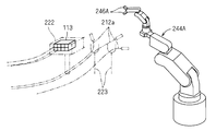
- the wire harness 110 is manufactured in a short time in a specific space (that is, a specific manufacturing location) among the analysis results, the real spaces R (1), R (2), and R (3). May be found.
- the movement of the sub-assembly 114 and the like in the specific space and the movement of the handling subject 40 are compared with those movements in the virtual three-dimensional space VR, which leads to an increase in manufacturing efficiency of the wire harness 110. Guess the movement that is. Then, the simulation is performed again by reflecting the movement.
- the handling subject 40 as the worker 42 (person) and the robot 44, it is possible to examine the efficiency of the work by the cooperative work of the person and the robot.
- the handling of the wire harness 110 can be simulated and examined in the virtual three-dimensional space VR, the handling of the wire harness 110 can be effectively optimized. .
- the simulation processing unit 160 simulates the movement of the electric wire 112 when the electric wire 112 is wired to the wire harness assembly drawing board 120 or the like in the virtual three-dimensional space VR. It is possible to simulate the presence or absence of the entanglement 112 and the interference between the electric wire 112 and the handling main body 40.
- the wire harness 110 is a flexible object, as the object data, the three-character original shape data of the sub-assembly 114, the arrangement state of the ends held by the electric wire holding bar 124, the three-character original shape data of the wire harness 110 Even if included, variations may occur within the range defined by them. For example, even if the location where the end portion of the sub assembly 114 is held by the electric wire holding bar 124 is defined, the end portion of the sub assembly 114 is bent and may vary within the range.
- work which inserts the edge part of the electric wire of the subassembly 114 into the connector 113 of the other subassembly 114 may generate
- the end of the electric wire may be temporarily held on the electric wire temporary holder on the wire harness assembly drawing board 120.
- the posture of the electric wire on the electric wire temporary holder may vary, and when a plurality of electric wires are temporarily held on the electric wire temporary holder, the upper and lower sides thereof may vary.
- the object data generating unit realized by one function of the computer performs physical processing based on the initial object data.
- a configuration may be adopted in which data randomly distributed within a range in accordance with the general law is generated and the data is received as object data.
- the sub assembly 114 and the like are imaged by an imaging unit such as a two-dimensional or three-dimensional camera, and the imaging data obtained by the imaging unit is obtained. Based on this, it is preferable to control the robot. Therefore, the simulation processing unit 160 generates captured image data corresponding to the captured image of the sub-assembly 114 from a predetermined direction based on the data dispersed within the range in accordance with the physical law, and based on the captured image data. Thus, it is preferable to recognize the actual position of the electric wire 112, execute a simulation based on a plurality of types of handling instruction data, and evaluate handling suitable for the captured image data.
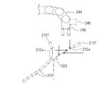
- the wire harness is configured by a combination of a plurality of subassies 114.
- one connector 113 of one sub-assembly 114 has an empty cavity 113e.
- one sub-assembly 114 is held in a predetermined arrangement form on the electric wire holding bar 124.
- simulation is performed by the robot 244 so as to be transferred onto the wire harness assembly drawing board based on the object data, handling main body data, and handling instruction data.
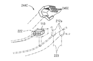
- the connector 113 is set on the connector holder 222 erected on the wire harness assembly drawing board.
- the other sub-assembly 114 has a wire terminal portion 212a to be inserted into the empty cavity 113e of the connector 113.
- the wire terminal portion 212 a is a portion where the terminal 212 T is connected to the end portion of the wire 212 but is not inserted into the connector 113.
- the other sub-assembly 114 is also held in a predetermined arrangement form on the electric wire holding bar 124. Then, in the virtual three-dimensional space VR, the robot 244 performs a simulation based on the object data, the handling subject data, and the handling instruction data so as to be transferred onto the wire harness assembly drawing board.
- the electric wire terminal part 212a is hold
- the wire terminal holder 223 is, for example, a member having an upper portion formed in a U shape, and is held so that the wire terminal portion 212a is hooked on the wire terminal holder 223.
- a plurality of electric wire terminal holders 223 are provided around the connector holder 222, and one electric terminal portion 212a is held in each electric wire terminal holder 223.
- the holding form of the electric wire terminal portion 212a in each electric wire terminal portion 212a is constant.
- the wire terminal portion 212a is held in an orthogonal posture with respect to the wire terminal holder 223, and the extension dimension of the wire terminal portion 212a relative to the wire terminal holder 223 (the wire end portion 212a relative to the wire terminal portion 212a). The holding position) is constant.
- one or a plurality of handling instruction data of the robot 244 are set, and the object in the virtual three-dimensional space VR is set based on the handling instruction data.
- One simulation method simulates the movement and the movement of the robot 244.
- the robot 244 holds a certain position from the end of the wire terminal portion 212 a and sequentially enters the empty cavities 113 a of the connectors held by the connector holder 222. What is necessary is just to perform the simulation in virtual three-dimensional space VR so that it may insert.
- the object data in the electric wire terminal holder 223 may not sufficiently reflect the actual situation.
- the wire terminal portion 212 a may be bent before and after the portion held by the wire terminal holder 223.
- the extension dimension of the electric wire terminal portion 212a with respect to the electric wire terminal holder 223 may vary from one electric wire terminal portion 212a to another.
- a plurality of wire terminal portions 212a may be held with respect to one wire terminal holding tool 223, and the presence or absence of crossing, the vertical relationship of crossing, and the like may be different.
- a simulation in a virtual three-dimensional space is performed for each of the plurality of types of data varied as described above, based on the handling subject data and the handling instruction data.
- an image of the periphery 0 of the wire terminal holder 223 is captured by an imaging unit 246 such as a camera, and the wire terminal is based on the captured image data. It is preferable to recognize the position of the part 212a and control the operation of the robot 244 based on the recognized position of the wire terminal part 212a to perform the assembly work of the wire harness.
- imaging data from above is obtained by the imaging unit 246.
- the imaging data can be generated as image data observed from an upper viewpoint based on a plurality of types of data that vary in the virtual three-dimensional space VR.
- one electric wire terminal portion 212 a is held near one side of the electric wire terminal holder 223, and the other one electric wire terminal portion 212 a is held near the other side of the electric wire terminal holder 223.
- the two electric wire terminal portions 212 a are held in a state where they intersect at the front side and the other side of the electric wire terminal holder 223.
- one electric wire terminal portion 212 a is held near one side of the electric wire terminal holder 223, is greatly bent beyond the electric wire terminal holder 223, and the other one electric wire terminal portion 212 a is held by the electric wire terminal.
- the tool 223 is held on the other side. Based on the data corresponding to the imaging data, the position of the electric wire terminal portion 212 a is recognized, and the electric wire terminal portion 212 a is held by the hand 245 of the robot 244.
- the robot 244 holds the wire terminal portion 212 a held by the wire end holder 223 and inserts it into the empty cavity 113 a of the connector 113 as a plurality of types of operating subjects. It is preferable that data is set and a plurality of types of simulations are performed in the virtual three-dimensional space VR based on the plurality of types of operation subject data.
- the robot 244 is recognized based on the data corresponding to the imaging data.
- the direction in which the hand 245 is going to hold the wire terminal portion 212a (from the top or from either side), the holding position (the position from the terminal 212t of the wire terminal portion 212a, FIG. (See also the position indicated by a two-dot chain circle in FIG. 18) and the like.
- the hand 245 when considering the operation of inserting the hand 245 of the robot 244 into the empty cavity 113 a of the connector 113, the hand 245 is connected to the other electric wires 212 according to the direction of the hand 245 with respect to the terminal 212 t. Interference conditions change. For example, if the hand 245 is oriented sideways with respect to the terminal 212 t inserted into the empty cavity 113 a of the connector 113, the hand 245 tends to interfere with the side electric wire 112.
- the ease of interference of the wire terminal portion 212a with the connector 113 varies depending on the position where the hand 245 holds the wire terminal portion 212a. For example, assuming that the electric wire 212 of the electric wire terminal portion 212a is bent more than a predetermined bending radius, if the hand 245 holds the vicinity of the terminal 212t of the electric wire terminal portion 212a, the electric wire terminal portion 212a is a connector. It is difficult to interfere with 113. On the other hand, if the hand 245 holds the far end of the terminal 212t of the electric wire terminal portion 212a, the electric wire terminal portion 212a easily interferes with the connector 113.
- the terminal 212t when inserting the wire terminal portion 212a into the cavity 113a, the terminal 212t needs to deform the lance 113b in the cavity 113a, and for that purpose, a certain amount of insertion force is applied. There is a need. However, if the hand 245 holds the far end of the terminal 212t of the electric wire terminal portion 212a, the electric wire 212 may be buckled, and the insertion operation of the electric wire terminal portion 212a may fail.
- a plurality of types of handling instruction data in which the direction of obtaining the electric wire terminal portion 212a, the holding position, the insertion direction, and the like are changed are received, and the handling main body data and the Based on a plurality of types of handling instruction data, a simulation in a virtual three-dimensional space is performed according to physical laws. Then, the contents of the optimum handling instruction are searched.
- Multiple types of handling instruction data may be input by an operator, or a handling instruction data generation unit that can be realized as one function of a computer can operate a handling subject based on object data, handling subject data, etc. It is also possible to automatically generate handling instruction data for a simple object.
- the present specification describes that the object data includes a plurality of types of data that vary depending on the flexibility of the wire harness, and in this case, based on each of the plurality of types of data that varies.
- simulation is performed in a virtual three-dimensional space VR.
- handling instruction data suitable for a plurality of types of data is selected.
- the mechanical sensor 247A (or 247B) provided in the hand 245 of the robot 244 is inserted. It is possible to determine whether or not the terminal 212t has been inserted normally based on the output result. In this case, if the terminal 212t is normally inserted, the insertion force increases when the lance 113b is deformed, but is detected as a value that does not exceed a predetermined upper limit as a whole. On the other hand, as shown in FIG.
- the insertion force and the pulling force can be detected by providing the hand 245 with a mechanical sensor 247A (or 247B).
- a mechanical sensor 247A or 247B
- the installation position, installation posture, and the like can affect the detection accuracy.
- the mechanical sensor 247 is provided on the finger 246 of the hand 245 of the robot 244 (see the mechanical sensor 247A) and when it is provided at the proximal end of the hand 245 (dynamic sensor 247B)
- the detected insertion force and extraction are detected.
- the power can change.
- the situation where the wire terminal portion 212a and the connector 113 interfere can also affect the detected insertion force and extraction force.
- the physical condition of the object can be detected by various sensors in addition to the mechanical sensor.
- the deformed lance 113b returns so as to jump up to the original shape, and thus generates sound or vibration. For this reason, it is possible to detect whether or not the terminal 212t is normally inserted into the cavity 113a by the sound sensor or the vibration sensor. Therefore, in the virtual three-dimensional space VR, the sound or vibration generated by the lance 113b is simulated according to a physical law according to a sound sensor provided on the hand 245 or the like, or a situation where the vibration is transmitted to the vibration sensor. It is also possible to consider whether or not it is possible to appropriately detect whether or not the terminal 212t has been normally inserted.
- the present specification has changed the installation position, installation posture, and the like of various sensors such as a mechanical sensor in order to grasp the physical state of the object or the like (for example, the insertion state of the terminal 212t).
- a plurality of types of handling main data are prepared, and a plurality of simulations (for example, a simulation related to a terminal insertion operation) are performed in the virtual three-dimensional space VR based on the plurality of types of handling instruction data. It is disclosed to perform a simulation of grasping the physical situation in the system.
- this application mode includes a plurality of types of data in which the object data varies according to the flexibility of the wire harness, or the simulation processing unit is based on the object data. It is more effective if a simulation is performed in the virtual three-dimensional space VR based on each of the plurality of types of dispersed data on the assumption that a plurality of types of data dispersed according to the flexibility of the wire harness is generated. It is.
- the insertion is performed again by correcting the insertion posture of the wire terminal portion 212a by the hand 245. Can be considered.
- the simulation is performed by changing various insertion postures of the electric wire terminal portion 212a by the hand 245, and it is also possible to find out how the electric wire terminal portion 212a can be easily inserted into the cavity 113a by correcting. .
- the wire harness is composed of a plurality of electric wires 212, when handling a certain electric wire 212, it is necessary to avoid or interfere with other electric wires 212 and to grip or move it. For this reason, it is thought that workability
- the robot 244A shown in FIG. 27 and the robot 244B shown in FIG. 28 are the same vertical articulated type robots, but the number of movable axes is different. For this reason, the robots 244A and 244B have different degrees of freedom when moving to move the object.
- the robot 244A illustrated in FIG. 27 grips an object with a pair of fingers 246A.
- the robot 244C illustrated in FIG. 29 includes fingers 246C imitating human fingers. For this reason, both robots 244A and 244C differ in the way of grasping the object and the dexterity.
- a simulation may be performed on each of a plurality of types of handling main body data indicating different types of robots 244A, 244B, and 244C based on handling instruction data and object data.
- handling main body data suitable for certain object data.
- the handling main data includes a plurality of types of data in which the robot axis, the number of fingers, the thickness, etc. are changed, and the plurality of types of handling main data include Based on this, it is disclosed that a plurality of simulations (for example, a simulation related to a terminal insertion operation) can be performed in a virtual three-dimensional space VR and a handling subject suitable for a predetermined object or work can be selected.
- a plurality of simulations for example, a simulation related to a terminal insertion operation
- the third application example is based on the assumption that the object data includes a plurality of types of data that vary depending on the flexibility of the wire harness, and instead of or in addition to this.
- a plurality of simulations are processed in the virtual three-dimensional space VR on the premise that a plurality of types of handling main body data having different installation positions and installation postures of various sensors such as a dynamic sensor are prepared. This is more effective.
- FIG. 30 is a diagram schematically showing a simulation to which the first to third application examples are applied.
- a plurality of object variation data are prepared, in which the object is randomly dispersed within a range that complies with the physical laws.
- variation data of the handling main data to be accepted a plurality of data in which the robot type (number of axes, number of fingers, finger thickness, sensor position, posture, etc.) is changed is prepared.
- the handling instruction data includes data given on the basis of absolute coordinates regarding the direction, position, etc. held by the hand, it is recognized in the imaging data (or data generated as an equivalent thereof). Data that is relatively defined with respect to the wire terminal portion 212a may be included.
- the data of each of the above variations may be artificially set by an operator, may be created based on an example in a real space, or may be created within the range according to 3D design data, physical laws, etc. May be automatically created by a computer by representing discrete variables (positions at which the object varies, robot coordinates, etc.) as discrete variables and combining the discrete variables.
- the simulation processing unit Based on one of the variation data of the target object, one of the variation data of the handling main data, and one of the variation data of the handling instruction data, the simulation processing unit performs the processing on the target in the virtual three-dimensional space VR.
- a movement of a certain wire harness and a movement of a robot that is a main subject of handling are simulated, and an evaluation value of handling is obtained based on the simulation result.
- the handling situation in the real space R (1), R (2), R (3)... Is imaged by an imaging unit such as a stereo camera, and the connector is based on the imaging data. It is also possible to recognize the positions of terminals, electric wires, etc., and find a more suitable work procedure by a so-called machine learning method based on the recognition result. Further, it is conceivable to modify the algorithm, data, etc. of the simulation processing based on the imaging data, for example, to make the contents of the variation data of the object more realistic.
- the work performed by the operator may be reflected in the simulation process.
- the wire harness 110 when assembling the wire harness 110 to a vehicle body, door, or the like, a plurality of connectors are connected to electrical devices on the vehicle side or connectors of other wire harnesses, and vehicle fixing parts are fixed to the vehicle. Work is required. Since many combinations of these work orders are conceivable, the examination of the work order affects workability when the wire harness 110 is assembled to the vehicle.
- the evaluation value not only quantitative parameters such as work time but also qualitative parameters may be considered. For example, based on a certain hypothesis based on the quality improvement process, the manufacturing time reduction process, the presence / absence of mutual cooperation work, etc., the handling team satisfaction, the satisfaction of the handling person itself, etc. are quantified as qualitative parameters.
- the evaluation value may be obtained by adding it.
- the incident situation is preferably created based not only on cases virtually assumed by the designer or the like but also on cases in the real space.
- the incident situation includes, for example, a situation where the electric wire 112 or the sub assembly 114 held on the electric wire holding bar 124 has dropped, a situation where the attaching work of the binding component 115 etc. has failed and the work should be repeated, and an electric wire holding bar 124 It is conceivable that the electric wires 112 that have been held are intertwined and one or a combination of a plurality of situations in which an operation to solve this is necessary. By incorporating these incident situations and performing simulations, it becomes possible to study optimization of process design that can respond quickly according to various situations.
- each handling simulation device 150 is a single computer or a group of computers that performs the above-described series of optimization processes, and by providing a plurality of these, each handling simulation device 150 Then, the above series of optimization processes are executed. Then, by replacing the evaluation values of the simulation results in each handling simulation device 150 with each other, more efficient optimization can be performed by computer processing or determination by an operator, or by complex processing thereof. It is advanced.
- each of the handling simulation devices 150 may be provided in one place, or at least a part of the handling simulation device 150 may be provided in each factory (or a manufacturing factory group described later). .
- the target wire harness is divided into a plurality of blocks, and simulation and optimization processes are performed for each simulation device 150 based on different handling instruction data set according to each block.
- optimization can be advanced more efficiently. In this case, it is desirable to divide the block into places where there is little or no influence on optimization.
- each structure demonstrated by said each embodiment and each modification can be suitably combined unless it mutually contradicts.
Abstract
対象物のハンドリングの最適化を容易に行えるようにすることを目的とする。対象物データ、ハンドリング主体データ及びハンドリング指示データに基づいて、仮想3次元空間における対象物の動きとハンドリング主体の動きとをシミュレーションする。仮想3次元空間における対象物の動きとハンドリング主体の動きのシミュレーション結果に基づいて、対象物のハンドリングの評価値を求め、対象物の工程設計を決める。必要に応じて、現実空間におけるハンドリング状況を反映して、再シミュレーションを行い、最適化を検討する。
Description
この発明は、ワイヤーハーネス等の対象物のハンドリングを最適化するための技術に関する。
非特許文献1及び2は、車両等に組付けられるワイヤーハーネスの設計を行うための技術を開示している。
非特許文献3は、立体映像の試作車の上で、ハーネスレイアウトを設計する技術を開示している。
非特許文献4は、メインディスプレイを作業台と見立て、このメインディスプレイ上で、仮想的にハーネスの配線作業を行う技術を開示している。
非特許文献5は、曲げ及びねじれを表す3変数と、伸縮を表す1変数とによって、線状物体等を表現し、これにより、線状物体等の変形形状を導出する手法を開示している。この非特許文献5では、線状物体等の変形形状をシミュレーションすることによって、マニピュレータ等によって線状物体を取扱う際に、ハンドの軌道生成を行うシステムを構築可能であると記載している。
ポウヤンヌ・エリサ(POUYANNE Elisa)、「自働化モジュラー/KSKハーネス設計(Automating Modular/"KSK" Harness Design)」、ワイヤー&ケーブルテクノロジーインターナショナルマガジン(Wire & Cable Technology International Magazine)、米国、2011年11月、第39巻、第6号、p.136-139
ジェイ・ニック(JAY Nick)、「車両ワイヤーハーネス設計のための基本設計フロー(Wire harness design Basic design flow for vehicle wire harness design)」、エレクトロニクスワールド(Electronics World)、英国、2005年11月、第111巻、1835号、p.32-35
永島博通、西崎誠、「ハーネス設計支援バーチャルリアリティシステム」、三菱自動車テクニカルレビュー、1998年04月、第10号、p.116-119
菱川浩二、河田幸男、中島奈央、木島竜吾、小鹿丈夫、加藤茂、谷口芳和、「ワイヤーハーネスの組み立て作業シミュレータの構築」、日本バーチャルリアリティ学会大会論文集、2000年09月18日、第5巻、p.21-24
若松栄史、「線状/帯状物体のマニピュレーション―ワイヤーハーネス/フレキシブル基板のハンドリング自動化に向けて―」、システム制御情報学会研究発表講演会講演論文集、2007年05月16日、第51巻、CD-ROM
ところで、ある対象物のハンドリング性をよくするためには、各作業の最適化、各作業順の最適化等を検討することが好ましい。
ワイヤーハーネスの製造は、ワイヤーハーネスの多様性、複雑性から、手作業や治具の工夫、作業手順に負うところが多く、そのためハンドリング性が大きな問題になる。ところが、非特許文献1~5では、コンピュータ上の2次元空間又は3次元空間において、ワイヤーハーネスが表現されているが、当該ワイヤーハーネスのハンドリング性に関する検討はなされていない。非特許文献5ではハンドリング自動化に関する検討がなされているが、静的に安定した形状の検討までであり、対象物の動きや、ワイヤーが撥ねる可能性のように潜在的な動きの可能性などハンドリングの最適化に重要な点については開示されていない。
このため、例えば、ワイヤーハーネスの製造作業又は車両への組付け作業の最適化の検討は、経験的知見、又は、現実空間における試行等によってなされるのが一般的であり、最適化の検討が困難となっていた。
そこで、本発明は、対象物のハンドリングの最適化を容易に行えるようにすることを目的とする。
上記課題を解決するため、第1の態様は、対象物のハンドリングシミュレーション装置であって、前記対象物の3次元データを含む対象物データを受付ける対象物データ受付部と、ハンドリング主体の可能動作データを含むハンドリング主体データを受付けるハンドリング主体データ受付部と、前記ハンドリング主体による前記対象物のハンドリング指示データを受付ける指示データ受付部と、前記対象物データと前記ハンドリング主体データと前記ハンドリング指示データとに基づいて、仮想3次元空間における前記対象物の動きと前記ハンドリング主体の動きとをシミュレーションするシミュレーション処理部と、前記仮想3次元空間における前記対象物の動きと前記ハンドリング主体の動きのシミュレーション結果に基づいて、前記対象物のハンドリングの評価値を求める評価値算出部とを備える。
第2の態様は、第1の態様に係る対象物のハンドリングシミュレーション装置であって、前記シミュレーション処理部は、物理法則に従って、前記対象物の動きをシミュレーションする物理演算部を含む。
第3の態様は、第1又は第2の態様に係る対象物のハンドリングシミュレーション装置であって、前記対象物がワイヤーハーネスであり、前記対象物データ受付部は、前記対象物データとして、ワイヤーハーネスの3次元データを含む対象物データを受付けるものである。
第4の態様は、第3の態様に係る対象物のハンドリングシミュレーション装置であって、前記指示データ受付部は、電線をワイヤーハーネス組立図板に布線する指示を含むハンドリング指示データを受付け、前記シミュレーション処理部は、前記仮想3次元空間における前記対象物の動きとして、前記電線をワイヤーハーネス組立図板に布線する際の前記電線の動きをシミュレーションするものである。
第5の態様は、第1~第4のいずれか1つの態様に係る対象物のハンドリングシミュレーション装置であって、前記指示データ受付部が、前記ハンドリング指示データを複数種類受付け、前記シミュレーション処理部は、前記複数種類の前記ハンドリング指示データのそれぞれに対して、仮想3次元空間における前記対象物の動きと前記ハンドリング主体の動きとをシミュレーションし、前記評価値算出部は、前記複数種類の前記ハンドリング指示データのそれぞれに対するシミュレーション結果に基づいて、前記対象物のハンドリングの評価値を求めるものである。
第6の態様は、第1~第5のいずれか1つの態様に係る対象物のハンドリングシミュレーション装置であって、現実空間における前記対象物のハンドリング状況データを取得する現実空間ハンドリング状況データ取得部からのハンドリング状況データを、前記対象物データ、前記ハンドリング主体データ及び前記ハンドリング指示データの少なくとも1つに反映させるものである。
第7の態様は、第6の態様に係る対象物のハンドリングシミュレーション装置であって、前記ハンドリング状況データは、現実空間において生じたインシデントな状況データを含むものである。
第8の態様は、第6又は第7の態様に係る対象物のハンドリングシミュレーション装置であって、前記現実空間ハンドリング状況データ取得部は、前記現実空間における前記対象物の動き及び前記ハンドリング主体の動きを取得するものである。
第9の態様に係る対象物のハンドリングシミュレーションシステムは、第1~第8のいずれか1つに係る対象物のハンドリングシミュレーション装置を複数備え、前記複数の対象物のハンドリングシミュレーション装置のそれぞれにおいて、前記ハンドリング主体データ及び前記ハンドリング指示データの少なくとも1つを異ならせて、シミュレーションするものである。
また、上記課題を解決するため、第10の態様は、コンピュータによって対象物のハンドリングをシミュレーションする方法であって、前記対象物の3次元データを含む対象物データを受付けるステップと、ハンドリング主体の可能動作データを含むハンドリング主体データを受付けるステップと、前記ハンドリング主体による前記対象物のハンドリング指示データを受付けるステップと、前記対象物データと前記ハンドリング主体データと前記ハンドリング指示データとに基づいて、仮想3次元空間における前記対象物の動きと前記ハンドリング主体の動きとをシミュレーションするステップと、前記仮想3次元空間における前記対象物の動きと前記ハンドリング主体の動きのシミュレーション結果に基づいて、前記対象物のハンドリングの評価値を求めるステップとを備える。
また、上記課題を解決するため、第11の態様に係る対象物の製造方法は、対象物の3次元データを含む対象物データと、ハンドリング主体の可能動作データを含むハンドリング主体データと、前記対象物のハンドリング指示データとに基づいて、コンピュータにおいて、仮想3次元空間における前記対象物の動きと前記ハンドリング主体の動きとをシミュレーションするステップと、前記仮想3次元空間における前記対象物の動きと前記ハンドリング主体の動きのシミュレーション結果に基づいて、前記対象物のハンドリング作業を決定するステップと、決定されたハンドリング作業に基づいてなされる現実空間における前記対象物のハンドリング状況データを取得するステップと、前記現実空間における前記対象物のハンドリング状況データを、前記対象物データ、前記ハンドリング主体データ、前記ハンドリング指示データ及び前記シミュレーションの処理に反映させて、前記対象物のハンドリング作業の最適化を検討するステップとを備える。
また、上記課題を解決するため、第12の態様に係る対象物のハンドリングシミュレーションプログラムは、コンピュータを、対象物の3次元データを含む対象物データを受付ける対象物データ受付部と、ハンドリング主体の可能動作データを含むハンドリング主体データを受付けるハンドリング主体データ受付部と、前記ハンドリング主体による前記対象物のハンドリング指示データを受付ける指示データ受付部と、前記対象物データと前記ハンドリング主体データと前記ハンドリング指示データとに基づいて、仮想3次元空間における前記対象物の動きと前記ハンドリング主体の動きとをシミュレーションするシミュレーション処理部と、前記仮想3次元空間における前記対象物の動きと前記ハンドリング主体の動きのシミュレーション結果に基づいて、前記対象物のハンドリングの評価値を求める評価値算出部と、として機能させるものである。
第1の態様によると、仮想3次元空間における対象物の動きとハンドリング主体の動きとをシミュレーションし、そのシミュレーション結果に基づいて、対象物のハンドリングの評価値を求めることができる。そして、その評価値を手がかりとして、対象物のハンドリングの最適化を容易に行える。
第2の態様によると、シミュレーション処理部は、物理法則に従って、前記対象物の動きをシミュレーションする物理演算部を含むため、対象物が剛体ではなく、柔軟物等である場合等にも、対象物の動きを適切にシミュレーションすることができる。これにより、対象物のハンドリングの評価値をより適切に求めることができ、対象物のハンドリングの最適化をより適切に行える。
ワイヤーハーネスのハンドリング作業は多様であり、また、作業順の多様性にも富む。そこで、第3の態様のように、このようなワイヤーハーネスのハンドリングをシミュレーションすることによって、ワイヤーハーネスのハンドリングの最適化を効果的に実施することができる。
第4の態様によると、シミュレーション処理部は、前記仮想3次元空間において電線をワイヤーハーネス組立図板に布線する際の前記電線の動きをシミュレーションするため、その作業中における電線の絡み、電線とハンドリング主体との干渉等の有無をシミュレーションすることができる。
第5の態様によると、複数種類の前記ハンドリング指示データの中から適したハンドリング指示データを決定することができ、対象物のハンドリングの最適化を容易に行える。
第6の態様によると、現実空間におけるハンドリング状況データを反映させて、より最適なシミュレーションを実施でき、対象物のハンドリングの最適化をより適切に行える。
第7の態様によると、初期のシミュレーション段階では想定困難なインシデントな状況をも考慮して、対象物のハンドリングの最適化を実施できる。
第8の態様によると、現実空間における対象物の動き及びハンドリング主体の動きを取得することで、ハンドリング状況データを取得することができる。
第9の態様によると、前記ハンドリング主体データ及び前記ハンドリング指示データの少なくとも1つを異ならせて、効率的にシミュレーションすることができる。
第10の態様によると、仮想3次元空間における対象物の動きとハンドリング主体の動きとをシミュレーションし、そのシミュレーション結果に基づいて、対象物のハンドリングの評価値を求めることができる。そして、その評価値を手がかりとして、対象物のハンドリングの最適化を容易に行える。
第11の態様によると、仮想3次元空間における対象物の動きとハンドリング主体の動きとをシミュレーションし、そのシミュレーション結果に基づいて、対象物のハンドリングの最適化を容易に行える。また、現実空間におけるハンドリング状況データを反映させて、より最適なシミュレーションを実施でき、対象物のハンドリングの最適化をより適切に行える。
第12の態様によると、仮想3次元空間における対象物の動きとハンドリング主体の動きとをシミュレーションし、そのシミュレーション結果に基づいて、対象物のハンドリングの評価値を求めることができる。そして、その評価値を手がかりとして、対象物のハンドリングの最適化を容易に行える。
{第1実施形態}
以下、第1実施形態について説明する。図1は対象物10のハンドリングをシミュレーションする処理及び現実空間を当該シミュレーションに反映させる処理を示す説明図であり、図2はハンドリングシミュレーション装置を含むシステムの全体構成を示す説明図である。
以下、第1実施形態について説明する。図1は対象物10のハンドリングをシミュレーションする処理及び現実空間を当該シミュレーションに反映させる処理を示す説明図であり、図2はハンドリングシミュレーション装置を含むシステムの全体構成を示す説明図である。
<全体構成について>
対象物10のハンドリングとしては、原材料を加工して、或は、各種部品を必要に応じて加工しつつ組合わせて工業製品等を製造する作業であること、或は、事前に準備された工業製品等を、他の組付対象物に組付ける作業等であることが想定される。前者の場合、対象物10としては、元となる原材料或は各種部品、及び、ハンドリングの結果得られる工業製品等であることが想定され、そのハンドリングとしては、その元となる原材料又は各種部品の加工又は組合わせ作業等が想定される。後者の場合、対象物10としては、事前に準備された工業製品及び組付対象物であることが想定され、そのハンドリングとしては、事前に準備された工業製品等を掴んで組付対象物に取付ける作業等が想定される。
対象物10のハンドリングとしては、原材料を加工して、或は、各種部品を必要に応じて加工しつつ組合わせて工業製品等を製造する作業であること、或は、事前に準備された工業製品等を、他の組付対象物に組付ける作業等であることが想定される。前者の場合、対象物10としては、元となる原材料或は各種部品、及び、ハンドリングの結果得られる工業製品等であることが想定され、そのハンドリングとしては、その元となる原材料又は各種部品の加工又は組合わせ作業等が想定される。後者の場合、対象物10としては、事前に準備された工業製品及び組付対象物であることが想定され、そのハンドリングとしては、事前に準備された工業製品等を掴んで組付対象物に取付ける作業等が想定される。
いずれにせよ、対象物10のハンドリングは、作業者42又はロボット44等のハンドリング主体40によって行われることが想定される。ハンドリング主体40は、1つであってもよいし、複数であってもよい。また、ハンドリング主体40は、作業者(人)のみであってもよいし、ロボットのみであってもよいし、或は、両者の組合わせであってもよい。以下では、作業者42又はロボット44等、対象物10をハンドリングする主体をハンドリング主体40と総称する場合がある。ロボットとしては、垂直多関節ロボットであってもよいし、直交ロボットであってもよいし、人型ロボットであってもよい。また、ロボットは、事前のティーチング等に従った動きのみを行うものであってもよいし、自律的な動きが可能なロボットであってもよい。
図1において、対象物10のハンドリングシミュレーション装置50は、一般的なコンピュータによって構成されている。コンピュータは、単一のコンピュータによって構成されていてもよいし、相互に連結しつつ分散して処理を行う複数のコンピュータによって構成されていてもよい。
ハンドリングシミュレーション装置50は、対象物10のハンドリングを検討するにあたって、その作業内容、作業順等を決定して工程設計書を作成する技術者等によって操作される。
このハンドリングシミュレーション装置50は、仮想3次元空間VRにおける対象物10の動きとハンドリング主体40の動きをシミュレーションし、そのシミュレーション結果に基づいてハンドリングの評価値を求める。このシミュレーション及び当該シミュレーション結果に基づいてハンドリングの評価値を求めることは、ハンドリング主体40の動きの内容等を変更して、複数回実施される。そして、その各評価値に基づいて、最も適したハンドリング主体40の動きの決定、すなわち、対象物10のハンドリングの最適化がなされる。これにより、対象物10をハンドリングするのに適した作業内容及び作業順等に基づいて、現実空間において実施されるべき工程設計書(データ)が作成される。この決定は、上記各評価値に基づいて技術者等によって全体或は部分的に手動でなされてもよい。
現実空間R(1)、R(2)、R(3)・・・では、工程設計書に従って、対象物10のハンドリングが実施される。現実空間R(1)、R(2)、R(3)・・・としては、生産工場等であることが想定される。
現実空間R(1)、R(2)、R(3)・・・には、現実空間R(1)、R(2)、R(3)・・・における対象物10のハンドリング状況データを取得する現実空間ハンドリング状況データ取得部46が設けられている。現実空間ハンドリング状況データ取得部46は、例えば、現実空間R(1)、R(2)、R(3)・・・における対象物10の動き、ハンドリング主体40の3次元的な動きを経時的に取得する装置、例えば、モーションキャプチャ装置であることが想定される。図2では、現実空間ハンドリング状況データ取得部46は、ステレオカメラ47と、当該ステレオカメラ47からの映像信号を処理して対象物10及びハンドリング主体40の3次元的な動きを経時的に取得する3次元処理部を含む工場側端末装置48とを備える装置として示されている。
現実空間R(1)、R(2)、R(3)・・・のそれぞれに設置された工場側端末装置48は、通信網49を介してハンドリングシミュレーション装置50と通信可能に接続されている。ここでは、通信網49は、有線式であっても無線式であってもよいし、また、公衆通信網であっても専用回線による通信網であってもよい。これにより、ハンドリングシミュレーション装置50は、現実空間R(1)、R(2)、R(3)・・・のそれぞれにおけるハンドリング状況データを取得できる。
そして、ハンドリングシミュレーション装置50は、ハンドリング状況データを反映して、仮想3次元空間VRにおける対象物10の動きとハンドリング主体40の動きを再度シミュレーションすることができる。結果、現実空間R(1)、R(2)、R(3)・・・におけるハンドリング状況を加味して、さらに適したハンドリング主体40の動きの決定、すなわち、対象物10のハンドリングの最適化がなされる。そして、再検討された結果が、修正された工程設計書として現実空間R(1)、R(2)、R(3)・・・に与えられ、現実空間R(1)、R(2)、R(3)・・・では、修正された工程設計書に基づくハンドリングが実施される。
上記が複数回繰返しなされることで、より適した最適化が実施されることになる。
なお、現実空間(1)、R(2)、R(3)・・・における対象物10のハンドリングは、特定の国又は複数の国に跨って複数箇所で実施される可能性がある。また、最適化された結果は、なるべく迅速に現実空間(1)、R(2)、R(3)・・・のそれぞれに伝達されることが好ましい。このため、本ハンドリングシミュレーション装置50を含むシステムは、クラウドコンピューティングシステムによって実現されてもよい。
<ハンドリングシミュレーション装置>
図3はハンドリングシミュレーション装置50のブロック図である。ハンドリングシミュレーション装置50は、対象物データ受付部52と、ハンドリング主体データ受付部54と、指示データ受付部56と、シミュレーション処理部60と、評価値算出部68とを備える。上記したように、ハンドリングシミュレーション装置50は、単一のコンピュータによって構成されていてもよいし、相互に連結しつつ分散して処理を行う複数のコンピュータによって構成されていてもよい。本ハンドリングシミュレーション装置50の演算動作は、予め格納されたソフトウェアプログラム(第2実施形態参照)によって実行される。
図3はハンドリングシミュレーション装置50のブロック図である。ハンドリングシミュレーション装置50は、対象物データ受付部52と、ハンドリング主体データ受付部54と、指示データ受付部56と、シミュレーション処理部60と、評価値算出部68とを備える。上記したように、ハンドリングシミュレーション装置50は、単一のコンピュータによって構成されていてもよいし、相互に連結しつつ分散して処理を行う複数のコンピュータによって構成されていてもよい。本ハンドリングシミュレーション装置50の演算動作は、予め格納されたソフトウェアプログラム(第2実施形態参照)によって実行される。
対象物データ受付部52は、ハンドリング対象となる対象物10の3次元データを含む対象物データを受付け可能に構成されている。対象物データとしては、ハンドリングが製造作業である場合には、製造目的となる製造物に関するデータ、その製造元となる原材料、部品のデータ等が想定され、ハンドリングが組付作業である場合には、事前に準備された物に関するデータ、組付対象物に関するデータ等が想定される。通常、対象物10の形状データは、事前に設計図等によって規定されている。かかる設計図の3次元データを含む対象物データが本対象物データ受付部52を介して受付けられ、ハンドリングシミュレーション装置50における記憶装置に格納される。
ハンドリング主体データ受付部54は、ハンドリング主体40の可能動作データを含むハンドリング主体データを受付け可能に構成されている。ハンドリング主体40が作業者42(人)である場合、ハンドリング主体データは、一般的な人体の骨格、各関節の自由度、可動範囲等を規定したデータによって構成される。また、ハンドリング主体40がロボット44である場合、当該ロボットの各アームの長さ、各関節の自由度及び可動範囲、可動軸の方向及び可動範囲等を規定したデータによって構成される。ハンドリング主体データは、一般的な人体モデル又は適用しようとするロボットの仕様データ等に基づいて作成される。
指示データ受付部56は、ハンドリング主体40による対象物10のハンドリング指示データを受付可能に構成されている。ハンドリング指示データは、対象物10をハンドリングするハンドリング主体40の動きを指示するデータであるともいえる。対象物10のハンドリングが製造作業である場合、ハンドリング指示データには、対象物10の元となる原材料又は部品を移動させるべくハンドリング主体40の動きを指示するデータ等が含まれる。対象物10のハンドリングが組付作業である場合、ハンドリング指示データには、対象物10の各部を順次組付対象物に組付ける手順等を指示するデータ等が含まれる。当初のハンドリング指示データの1つ又は複数は、技術者の経験的知見、対象物10の3字元形状等に基づく推論的知見に基づいて、技術者等によって作成される。
上記対象物データ受付部52、ハンドリング主体データ受付部54及び指示データ受付部56としては、他のコンピュータと通信して当該他のコンピュータに記憶されたデータを受付ける通信インターフェースであること、キーボード等のマンマシンインターフェースであること、事前に別途作成されたデータ記録媒体を読込む記録媒体のリーダであること等が想定される。
シミュレーション処理部60は、対象物データとハンドリング主体データとハンドリング指示データとに基づいて、仮想3次元空間における対象物10の動きとハンドリング主体40の動きとをシミュレーションする。すなわち、シミュレーション処理部60は、ハンドリング主体データとハンドリング指示データとに基づいて、仮想3次元空間におけるハンドリング主体40の動きを生成することができる。また、仮想3次元空間におけるハンドリング主体40の動きは、仮想3次元空間における対象物10のハンドリング内容、すなわち、動きを指示している。このため、シミュレーション処理部60は、ハンドリング主体データとハンドリング指示データと対象物データとに基づいて、仮想3次元空間における対象物10の動きをシミュレーションすることができる。
ここでは、シミュレーション処理部60は、ハンドリング主体動作シミュレーション処理部62と、物理演算部64とを含む。ハンドリング主体動作シミュレーション処理部62は、ハンドリング主体データとハンドリング指示データとに基づいて、仮想3次元空間におけるハンドリング主体40の動きを生成する。物理演算部64は、ハンドリング主体データとハンドリング指示データとで決る対象物10のハンドリング内容に基づき、物理法則(重力、剛性等)に従って、対象物10の動きをシミュレーションする。特に、対象物10が剛体ではなく、線状物又はフィルム状物のように柔軟物である場合には、対象物データに、3次元の形状データの他に、各部の質量データ、剛性データを含め、また、ハンドリング主体40の動きの速度等を考慮して、対象物10の動きをより現実に即してシミュレーションすることができる。
なお、ハンドリング主体40の動きのシミュレーション結果と、対象物10の動きのシミュレーション結果とを逐次相互に反映させ、一方の動きが他方の動きと干渉しないようにするとよい。
上記シミュレーション結果は、レンダリング処理部66によってレンダリング処理され、技術者によってハンドリングの様子を表示装置37等によって視認可能とされることが好ましい。
また、評価値算出部68は、上記シミュレーション結果に基づいて、対象物10のハンドリングの評価値を求める。評価値は、例えば、対象物10をハンドリングするのに要する総時間、総移動時間、動作量及びハンドリングに必要な力等に基づいて決定される消費エネルギーの少なくとも1つ、又は、それらの値を重み付けして算出した値等によって表される。
なお、ハンドリングする作業内容によっては、作業者42(人)が行うのに適したものと、ロボット44が行うのに適したものとが存在する。例えば、定型的な繰返し作業、力を要する作業等については、ロボット44が行うことが適する。また、複雑な作業、又は、人が複数の指を駆使して行えるような複雑な作業、非定常的な状況が生じ易く、その都度柔軟な判断に基づくことが必要となる作業については、作業者(人)による作業が適している。これらの場合には、各作業を作業者42(人)が行うのか、ロボット44が行うのかに応じて、上記評価値を修正することが好ましい。
これを、ハンドリング指示データを変更して、複数種類のハンドリング指示データに対して評価値を算出する。ハンドリング指示データの変更は、ハンドリングを構成する各作業内容、各作業内容順の変更、ハンドリング主体の変更(数の変更、作業者(人)からロボットへの変更又はその逆への変更)等である。これにより、対象物10のハンドリングに適したハンドリング指示データを決定することができる。この決定は、上記評価値に基づいてハンドリングシミュレーション装置50が決定してもよいし、技術者が評価値を見て決定してもよい。このハンドリング指示データに基づいて、技術者等によって、作業計画書(データ)が作成される。
また、このハンドリングシミュレーション装置50には、上記したように、現実空間R(1)、R(2)、R(3)・・・の現実空間ハンドリング状況データ取得部46が接続されている。ここでは、現実空間ハンドリング状況データ取得部46からのハンドリング状況データは、反映処理指示部69に入力される。
反映処理指示部69は、現実空間ハンドリング状況データ取得部46からのハンドリング状況データに基づいて、シミュレーション処理に反映させるべき内容を決定する。すなわち、上記シミュレーションを行う際に、現実空間における諸状況が全て反映されているとは限らない。例えば、提供される部品の形状が初期に規定された形状と異なっている場合があり得る。また、作業者は、ある作業内容を実施するとミスが生じ易い、又は、動きが遅くなり、結果、ハンドリングの時間が長くなってしまうといった事態が生じ得る。
そこで、反映処理指示部69は、現実空間ハンドリング状況データ取得部46からのハンドリング状況データに基づいて、シミュレーション処理に反映させるべき内容を決定し、対象物10のハンドリング状況データを、対象物データ、ハンドリング主体データ、ハンドリング指示データの少なくとも1つに反映させる。
例えば、反映処理指示部69は、現実空間ハンドリング状況データ取得部46において取得された現実空間R(1)、R(2)、R(3)・・・での対象物10の動き及びハンドリング主体40の動きと、仮想3次元空間VRにおけるそれらの動きとを比較し、異なる動きが発生した作業に関して、現実空間R(1)、R(2)、R(3)・・・での各動きに合せてハンドリング主体データ又はハンドリング指示データを修正し、シミュレーションし直すように指示する。これにより、上記と同様に、最適なハンドリング指示データを検討し直すことができる。
また、例えば、反映処理指示部69は、現実空間ハンドリング状況データ取得部46からのハンドリング状況データに含まれる対象物10の形状と対象物データとを比較することで、提供される部品の形状が初期に規定された形状と異なっていることを判定した場合には、現実空間R(1)、R(2)、R(3)・・・における対象物10の形状に合せて対象物データを修正し、シミュレーションし直すように指示する。これにより、上記と同様に、最適なハンドリング指示データを検討し直すことができる。
このように、反映処理指示部69は、初期のシミュレーション時には想定困難ではあるが、現実空間において生じたインシデントな状況データに基づいて、シミュレーションし直すように指示する。これにより、対象物10のハンドリングを現実空間R(1)、R(2)、R(3)・・・の状況に合わせて、最適化していくことができる。
また、現実空間R(1)、R(2)、R(3)・・・では、各作業者又は作業チームの工夫によって、作業効率が上がることがありうる。反映処理指示部69は、現実空間R(1)、R(2)、R(3)・・・のそれぞれの現実空間ハンドリング状況データを統計的に処理し、迅速に処理された作業を特定し、当該作業を他と比較することによって、効率のよい作業内容、手順等を特定し、これを反映してシミュレーションし直すように指示することもできる。これにより、現実空間R(1)、R(2)、R(3)・・・の一部の工夫ないし知見が、他の現実空間R(1)、R(2)、R(3)・・・の作業にも反映されるようにすることができる。
なお、反映処理指示部69における処理は、現実空間R(1)、R(2)、R(3)・・・における多様なハンドリング状況データを解析することによってなされることが好ましい。このため、現実空間R(1)、R(2)、R(3)・・・における多様なハンドリング状況データを解析するにあたっては、いわゆるビッグデータを分析処理する手法が用いられることが好ましい。
<対象物のハンドリングをシミュレーションする方法>
図4は対象物のハンドリングをシミュレーションする方法の全体的な流れを示すフローチャートである。
図4は対象物のハンドリングをシミュレーションする方法の全体的な流れを示すフローチャートである。
同図に示すように、ステップS1において、ハンドリングシミュレーション装置50において、仮想3次元空間VRにおけるハンドリング主体40及び対象物10の動きがシミュレーションされる。
次ステップS2において、シミュレーション結果に基づいて、評価値が算出される。
ステップS1及びS2が、異なるハンドリング指示に基づいて、複数回実施され、結果、初回検討段階において、最適化されたハンドリング指示が決定される。このハンドリング指示に基づいて、ステップS3において、工程設計がなされる。
ステップS4では、現実空間R(1)、R(2)、R(3)・・・において、工程設計書に基づく対象物10のハンドリングが実施される。
次ステップS5では、現実空間R(1)、R(2)、R(3)・・・におけるハンドリング状況が取得される。
そして、ステップS6において、現実空間R(1)、R(2)、R(3)・・・におけるハンドリング状況を反映して、仮想3次元空間VRにおけるシミュレーションが再度なされる。
この後、ステップS7において、シミュレーション結果に基づいて、評価値が算出される。
そして、ステップS8において、工程再検討がなされ、必要に応じて、工程設計書が修正される。
そして、ステップS4に戻り、現実空間R(1)、R(2)、R(3)・・・において、工程設計書に基づく対象物10のハンドリングが続けられる。
上記を繰返すことで、仮想3次元空間VRにおけるシミュレーション結果と、現実空間R(1)、R(2)、R(3)・・・における実際の状況とを相互に反映させて、対象物10のハンドリングの最適化を進めていくことができる。
<効果等>
以上のように、本実施形態によると、仮想3次元空間VRにおける対象物10の動きとハンドリング主体40の動きとをシミュレーションし、そのシミュレーション結果に基づいて、対象物10のハンドリングの評価値を求めることができる。そして、その評価値を手がかりとして、対象物10のハンドリングの最適化を容易に行える。
以上のように、本実施形態によると、仮想3次元空間VRにおける対象物10の動きとハンドリング主体40の動きとをシミュレーションし、そのシミュレーション結果に基づいて、対象物10のハンドリングの評価値を求めることができる。そして、その評価値を手がかりとして、対象物10のハンドリングの最適化を容易に行える。
特に、物理法則に従って、仮想3次元空間VRにおける対象物10の動きをシミュレーションすることにより、対象物10が剛体ではなく、柔軟物等である場合等にも、対象物10の動きを適切にシミュレーションすることができる。これにより、対象物10のハンドリングの評価値をより適切に求めることができ、対象物10のハンドリングの最適化をより適切に行える。
また、上記シミュレーション及びその評価値の三社鬱を、複数種類のハンドリング指示データに対して行うことで、複数種類のハンドリング指示データの中から適したハンドリング指示データを決定することができ、対象物10のハンドリングの最適化を容易に行える。
また、現実空間R(1)、R(2)、R(3)・・・におけるハンドリング状況データを反映させて、上記シミュレーション等を行うことにより、現実空間R(1)、R(2)、R(3)・・・における実際の状況を加味して、対象物10のハンドリングの最適化をより適切に行うことができる。
特に、現実空間R(1)、R(2)、R(3)・・・におけるハンドリング状況データが、初期のシミュレーション時には想定困難なインシデントな状況を含むようにすることで、対象物のハンドリングをより適切に実施できる。
なお、現実空間R(1)、R(2)、R(3)・・・におけるハンドリング状況データからして、発生頻度が希であるインシデントな状況等については、必ずしも最適化に反映させる必要はなく、品質への影響、最適化における製造方法変更の効率(生産性)などを考慮の上、無視してもよい。
また、ハンドリング状況データとしては、現実空間R(1)、R(2)、R(3)・・・における対象物10の動き及びハンドリング主体40の動き等を取得するとよい。
また、ハンドリングの最適化を実施できる結果、ロボット等によるハンドリングの自働化も容易となる。
{第2実施形態}
第2実施形態では、ワイヤーハーネスの製造作業を前提として、より具体的な実施形態について説明する。
第2実施形態では、ワイヤーハーネスの製造作業を前提として、より具体的な実施形態について説明する。
<前提>
すなわち、図5に示すように、ワイヤーハーネス110は、複数の電線112が車両における配線レイアウトに応じた布線形態に布線された状態で、結束されることにより製造される。
すなわち、図5に示すように、ワイヤーハーネス110は、複数の電線112が車両における配線レイアウトに応じた布線形態に布線された状態で、結束されることにより製造される。
上記ワイヤーハーネス110を製造するにあたっては、事前に、ワイヤーハーネス110を複数に分割したサブアッシー114が製造される。
サブアッシー114は、ワイヤーハーネス110を構成する複数の電線112の一部を事前にひとまとまりの形態としたものである。サブアッシー114においては、複数の電線112が共通するコネクタ113に接続されることで、1つのまとまった形態として取扱われる。サブアッシー114を構成する電線112のうち一部の電線112の一方の端部は、コネクタ113に接続されないままの状態とされていることがある。
ワイヤーハーネス110は、サブアッシー114及び電線112を複数組合わせることによって製造される。
また、サブアッシー114及び電線112は、ワイヤーハーネス組立図板120上で所定の布線形態となるように配設される。ワイヤーハーネス組立図板120上には、U字状の電線保持具122、コネクタ保持具等が立設されており、電線112又はコネクタ113をそれらの保持具122等に保持させることで、サブアッシー114及び電線112は、ワイヤーハーネス組立図板120上で所定の布線形態に保持される。
また、ワイヤーハーネス組立図板120上で、複数の電線112は、粘着テープ、結束バンド等の結束部品115によって結束される。また、ワイヤーハーネス110には、クランプ等と呼ばれる車両固定部品116、コルゲートチューブ等の保護部品117が取付られる。
このように、ワイヤーハーネス110は、電線112、サブアッシー114、結束部品115、車両固定部品116、保護部品117等の部品をハンドリングして、製造される。これらの各部品及びワイヤーハーネス110がハンドリングの対象物となる。本実施形態では、これらの部品を総称して、対象物10という場合がある。
上記のようなワイヤーハーネス110を製造するにあたっては、以下のような事情によりそのハンドリングの最適化を図ることが困難である。
まず、サブアッシー114及び電線112を所定の布線形態に応じて配設する作業、複数の電線112を結束する作業、車両固定部品116、保護部品117等を取付ける作業等が発生する。このため、作業内容が非常に多様である。
また、例えば、サブアッシー114及び電線112を所定の布線形態に応じて配設する作業を行うにあたっては、サブアッシー114及び電線112は、電線を保持するスリットが多数形成された電線保持バー124等によって所定の準備配列形態に保持される。そして、サブアッシー114の各端部及び電線112の各端部を順次ワイヤーハーネス組立図板120に配設する作業が発生する。サブアッシー114の各端部及び電線112の各端部を順次ワイヤーハーネス組立図板120に配設する作業順の組合わせは莫大である。
サブアッシー114及び電線112の準備配列形態及びサブアッシー114及び電線112の端部をワイヤーハーネス組立図板120上に布線していく作業順は、電線112同士の発生の有無に大きく影響を与える。また、大規模なワイヤーハーネス110においては、ワイヤーハーネス組立図板120の最大寸法は、数メートルを超えるため、サブアッシー114及び電線112の端部をワイヤーハーネス組立図板120上に布線していく作業順は、作業時の移動距離、すなわち、作業時間にも大きな影響を与える。
また、実際にワイヤーハーネス110を製造するにあたっては、作業者の人数変更、ワイヤーハーネス110自体の設計変更等が生じ得る。これらの予測困難である事情(インシデントな状況を含む)を想定して事前にハンドリングの最適化を検討することは困難であるし、また、当該予測困難な事情が実際に生じた場合でも、当該事情を考慮して、ハンドリングの最適化を検討することは困難である。
本実施形態では、上記第1実施形態で説明した形態を、ワイヤーハーネス110の製造作業に適用することで、当該ワイヤーハーネス110のハンドリングの最適化を容易に行えるようにする。
なお、ここでは、ワイヤーハーネス110のハンドリング主体40(製造主体)が、上記第1実施形態と同様に、作業者42又はロボット44等によって行われることを想定して説明する。第1実施形態と同様に、ハンドリング主体40は、1つであってもよいし、複数であってもよい。また、ハンドリング主体40は、作業者(人)のみであってもよいし、ロボットのみであってもよいし、或は、両者の組合わせであってもよい。
<全体構成>
図6はハンドリングシミュレーション装置を含むシステムの全体構成を示す説明図である。
図6はハンドリングシミュレーション装置を含むシステムの全体構成を示す説明図である。
<全体構成について>
ハンドリングシミュレーション装置150は、本ワイヤーハーネス110の工程設計を行う場所に設置されている。本場所において、工程設計者に、ワイヤーハーネス110の設計図(データ)が与えられ、工程設計者は、当該ワイヤーハーネス110を製造するのに適した工程設計を行うことになる。
ハンドリングシミュレーション装置150は、本ワイヤーハーネス110の工程設計を行う場所に設置されている。本場所において、工程設計者に、ワイヤーハーネス110の設計図(データ)が与えられ、工程設計者は、当該ワイヤーハーネス110を製造するのに適した工程設計を行うことになる。
ハンドリングシミュレーション装置150は、ワイヤーハーネス110のハンドリング内容を検討する(工程設計を行う)にあたって、工程設計者等によって操作される。
このハンドリングシミュレーション装置150は、仮想3次元空間VRにおける電線112、サブアッシー114、結束部品115、車両固定部品116、保護部品117の動きと、ハンドリング主体40の動きをシミュレーションし、そのシミュレーション結果に基づいてハンドリング(製造作業)の評価値を求める。このシミュレーション及び当該シミュレーション結果に基づいてハンドリングの評価値を求めることは、ハンドリング主体40の動きの内容、電線保持バー124におけるサブアッシー114の配列等を変更して、複数回実施される。そして、その各評価値に基づいて、最も適したハンドリング主体40の動きの決定、すなわち、対象物10のハンドリングの最適化がなされる。これにより、対象物10をハンドリングするのに適した作業内容及び作業順等に基づいて、現実空間において実施されるべき工程設計書(データ)が作成される。この最終的な決定は、評価値に基づいて技術者等によって全体又は部分的になされてもよい。
現実空間R(1)、R(2)、R(3)・・・では、工程設計書に従って、対象物10のハンドリングが実施される。現実空間R(1)、R(2)、R(3)・・・としては、ワイヤーハーネス110の生産工場等であることが想定される。
現実空間R(1)、R(2)、R(3)・・・には、上記第1実施形態と同様に、現実空間ハンドリング状況データ取得部146が設けられている。ここでは、現実空間ハンドリング状況データ取得部146は、ステレオカメラ147と、当該ステレオカメラ147からの映像信号を処理して対象物及びハンドリング主体40の3次元的な動きを経時的に取得する3次元処理部を含む工場側端末装置148とを備える装置として示されている。ハンドリング主体40が作業者42である場合には、当該作業者42にマーカーを取付けることで、当該作業者42の動きをより正確に取得することができる。
現実空間ハンドリング状況データ取得部146の工場側端末装置148は、上記第1実施形態と同様に通信網49を介してハンドリングシミュレーション装置150と通信可能に接続されている。このため、各現実空間R(1)、R(2)、R(3)・・・におけるそれぞれのハンドリング状況データは、ハンドリングシミュレーション装置150に送信される。
そして、ハンドリングシミュレーション装置150は、ハンドリング状況データを反映して、仮想3次元空間VRにおける対象物10の動きとハンドリング主体40の動きを再度シミュレーションすることができる。結果、現実空間R(1)、R(2)、R(3)・・・におけるハンドリング状況を加味して、さらに適したハンドリング主体40の動きの決定、すなわち、対象物10のハンドリングの最適化がなされる。そして、再検討された結果が、修正された工程設計書として現実空間R(1)、R(2)、R(3)・・・に与えられ、現実空間R(1)、R(2)、R(3)・・・では、修正された工程設計書に基づくハンドリングが実施される。
上記が複数回繰返しなされることで、より適した最適化が実施されることになる。
<ハンドリングシミュレーション装置>
図7はハンドリングシミュレーション装置150のブロック図である。ハンドリングシミュレーション装置150は、第1実施形態で説明したように、一般的なコンピュータによって構成されている。すなわち、ハンドリングシミュレーション装置150は、マイクロプロセッサと、マイクロプロセッサと結合された記憶部とを有している。記憶部は、RAM(Random Access Memory)、フラッシュメモリ、EPROM(Erasable Programmable ROM)、ハードディスク装置等によって構成されている。記憶部は、は、各種の情報やデータ等を格納し、またマイクロプロセッサが実行するプログラムを格納し、また、プログラムを実行するための作業領域を提供する。このマイクロプロセッサと記憶部とによって、シミュレーション処理部160、評価値算出部168等の諸機能部が実現される。
図7はハンドリングシミュレーション装置150のブロック図である。ハンドリングシミュレーション装置150は、第1実施形態で説明したように、一般的なコンピュータによって構成されている。すなわち、ハンドリングシミュレーション装置150は、マイクロプロセッサと、マイクロプロセッサと結合された記憶部とを有している。記憶部は、RAM(Random Access Memory)、フラッシュメモリ、EPROM(Erasable Programmable ROM)、ハードディスク装置等によって構成されている。記憶部は、は、各種の情報やデータ等を格納し、またマイクロプロセッサが実行するプログラムを格納し、また、プログラムを実行するための作業領域を提供する。このマイクロプロセッサと記憶部とによって、シミュレーション処理部160、評価値算出部168等の諸機能部が実現される。
また、上記マイクロプロセッサ及び記憶部等に、入出力回路、バス回路等を通じて接続された入力インターフェースが、対象物データ受付部152と、ハンドリング主体データ受付部154と、指示データ受付部156としての機能を実現する。
なお、第1実施形態で説明したように、ハンドリングシミュレーション装置150は、単一のコンピュータによって構成されていてもよいし、相互に連結しつつ分散して処理を行う複数のコンピュータによって構成されていてもよい。
対象物データ受付部152は、第1実施形態で説明した対象物データ受付部52と同様構成である。本実施形態では、対象物データとしては、ワイヤーハーネス110を構成する各部品(電線112、サブアッシー114、結束部品115、車両固定部品116、保護部品117)の3次元データを含むデータが想定される。電線112、サブアッシー114に関するデータについては、初期形状、すなわち、電線保持バー124によって保持された端部の配列状態に従った3次元データが含まれる。また、電線112、サブアッシー114は、それらの取扱途中に変形する。すなわち、電線保持バー124からワイヤーハーネス組立図板120上に、電線112,サブアッシー114の端部を掴んで移動させる際に、電線112,サブアッシー114は変形する。このため、電線112、サブアッシー114の変形を、物理法則に従ってシミュレーションできるようにするために、電線112,サブアッシー114は、それらの3次元形状データ(電線112のデータ及びコネクタ113のデータ等)に加えて、各部の剛性、質量によって規定されていることが好ましい。例えば、電線112,サブアッシー114は、ソリッドモデル等によって規定されていることが好ましい。
かかる対象物データは、本対象物データ受付部152を介して受付けられ、ハンドリングシミュレーション装置150における記憶装置に格納される。
ハンドリング主体データ受付部154は、ハンドリング主体40の可能動作データを含むハンドリング主体データを受付け可能に構成されている。ハンドリング主体40が作業者42(人)である場合、ハンドリング主体データは、一般的な人体の骨格、各関節の自由度、可動範囲等を規定したデータによって構成される。ハンドリング主体の動きと他の部分との干渉の有無をより正確にシミュレーションするためには、ハンドリング主体データは、一般的な人体の骨格、各関節の自由度、可動範囲等を規定したキーフレームを、人体の表面(肌、衣服)等を規定したスキンデータで覆ったデータ等によって規定されていることが好ましい。また、ハンドリング主体40がロボット44である場合、当該ロボットの各アームの長さ、各関節の自由度及び可動範囲、可動軸の方向及び可動範囲等を規定したデータによって構成される。ハンドリング主体データは、一般的な人体モデル又は適用しようとするロボットの仕様データ等に基づいて作成される。
指示データ受付部156は、ハンドリング主体40による対象物10のハンドリング指示データを受付可能に構成されている。ハンドリング指示データは、対象物10をハンドリングするハンドリング主体40の動きを指示するデータであるともいえる。ここでは、指示データとして、電線112、サブアッシー114の初期状態に応じて、その各端部をワイヤーハーネス組立図板120上の所定位置(各保持具の位置又は保持具間の位置)に移動させる位置、順序等を規定したデータ、結束部品115、車両固定部品116、保護部品117を取付ける位置、作業順等を規定したデータ等が想定される。
上記したように、ワイヤーハーネス110を製造するにあたっては、作業内容、作業順等に関して多様性があり、作業データとしては多数の組合わせ例が考えられる。指示データの1つ又は複数自体は、技術者の経験的知見、対象物10の3字元形状等に基づく推論的知見等に基づいて、技術者等によって作成することができる。勿論、指示データは、現実空間において試行を行い、当該試行結果に基づいて作成されてもよい。
シミュレーション処理部160は、対象物データとハンドリング主体データとハンドリング指示データとに基づいて、仮想3次元空間における電線112、サブアッシー114、結束部品115,車両固定部品116、保護部品117、ワイヤーハーネス110等の動きとハンドリング主体40の動きとをシミュレーションする。すなわち、シミュレーション処理部160は、ハンドリング主体データとハンドリング指示データとに基づいて、仮想3次元空間におけるハンドリング主体40の動きを生成することができる。また、仮想3次元空間におけるハンドリング主体40の動きは、仮想3次元空間における電線112、サブアッシー114、結束部品115,車両固定部品116、保護部品117等のハンドリング内容、すなわち、動きを指示している。このため、シミュレーション処理部160は、ハンドリング主体データとハンドリング指示データと対象物データとに基づいて、仮想3次元空間における電線112、サブアッシー114、結束部品115,車両固定部品116、保護部品117等の動きをシミュレーションすることができる。
ここでは、シミュレーション処理部160は、ハンドリング主体動作シミュレーション処理部162と、物理演算部164とを含む。ハンドリング主体動作シミュレーション処理部162は、ハンドリング主体データとハンドリング指示データとに基づいて、仮想3次元空間におけるハンドリング主体40の動きを生成する。物理演算部164は、ハンドリング主体データとハンドリング指示データとで決る電線112、サブアッシー114等の動きに基づき、物理法則(重力、剛性等)に従って、電線112、サブアッシー114の動きをシミュレーションする。
すなわち、電線112、サブアッシー114は線状の柔軟物であり、上記したように、各部の剛性及び質量等を含む3字元形状データによって特定されている。そして、ハンドリング主体データとハンドリング指示データとで決る電線112又はサブアッシー114の保持位置、移動方向、速度等を考慮した上で、物理法則(重力、剛性等)に従って、電線112、サブアッシー114の動きをより正確にシミュレーションすることができる。なお、この際、電線112、サブアッシー114等の各状態での位置エネルギー又は位置エネルギーの変動、それらを動かす際に必要は運動エネルギー等を計算していくこともできる。これらは、ワイヤーハーネス110を製造する際の効率性に影響を与えうるため、評価値を算出する際のパラメータとして考慮されてもよい。
なお、ハンドリング主体40の動きのシミュレーション結果と、対象物10の動きのシミュレーション結果とを逐次相互に反映させ、一方の動きが他方の動きと干渉しないようにするとよい。
上記シミュレーション結果は、レンダリング処理部166によってレンダリング処理され、技術者によってハンドリングの様子を表示装置37等によって視認可能とされることが好ましい(図9参照)。
また、評価値算出部168は、上記シミュレーション結果に基づいて、電線112、サブアッシー114等のハンドリングの評価値を求める。評価値は、例えば、ワイヤーハーネス110を製造するのに要する総時間、総移動時間、動作量及びハンドリングに必要な力等に基づいて決定される消費エネルギーの少なくとも1つ、電線112同士の絡み合いの有無又は回数等をパラメータとして、それらのパラメータを重み付けして算出した値等によって表される。なお、評価値を算出する式(特に、重み付けの係数)は、現実空間R(1)、R(2)、R(3)・・・での状況に応じて最適な評価式となるように、見直していくことが好ましい。
また、このハンドリングシミュレーション装置150には、上記したように、現実空間R(1)、R(2)、R(3)・・・の現実空間ハンドリング状況データ取得部146が接続されている。ここでは、現実空間ハンドリング状況データ取得部146からのハンドリング状況データは、反映処理指示部169に入力される。反映処理指示部169の機能も、マイクロプロセッサと記憶部とによって実現される。
反映処理指示部169は、現実空間ハンドリング状況データ取得部146からのハンドリング状況データに基づいて、シミュレーション処理に反映させるべき内容を決定する。
反映処理指示部69は、現実空間ハンドリング状況データ取得部46からのハンドリング状況データに基づいて、シミュレーション処理に反映させるべき内容を決定し、対象物10のハンドリング状況データを、対象物データ、ハンドリング主体データ、ハンドリング指示データの少なくとも1つに反映させる。これにより、再度、上記シミュレーション処理が実行され、より適切なハンドリングが検討される。
<ハンドリングシミュレーション処理の内容>
図8はハンドリングシミュレーション処理を実行するためのプログラムの流れを示すフローチャートである。
図8はハンドリングシミュレーション処理を実行するためのプログラムの流れを示すフローチャートである。
まず、ステップS11において、対象物データの受付がなされたか否かが判定される。YESと判定されると、ステップS12に進み、ハンドリング主体データが受付けられたか否かが判定される。YESと判定されると、ステップS13に進み、指示データが受付けられたか否かが判定される。YESと判定されると、ステップS14に進む。なお、ステップS11~S13において、各データは、本処理を行うより前に受付けられ、事前に記憶部に記憶されている場合があり得る。
ステップS14では、電線112、サブアッシー114等の動き、及び、ハンドリング主体40の動きがシミュレーションされる。シミュレーション結果は、必要に応じて、表示装置137に表示される(図9参照)。
次ステップS15では、シミュレーション結果に基づいて、評価値が算出される。
上記シミュレーションが、少なくとも指示データを変えて複数回実施される。例えば、電線保持バー124における電線112、サブアッシー114の整列位置を変えると、ハンドリング主体40による電線112、サブアッシー114の移動位置、作業順は変るため、その変更に応じて指示データを変更する。また、結束部品115、車両固定部品116、保護部品117等の取付け順を変えた場合でも、その変更に応じて指示データを変える。
そして、相互に異なる指示データに基づいて上記シミュレーションを実施すると、異なる指示データ毎(つまり、異なる製造方法毎)に上記評価値が算出され、一通りの処理を終了する。
設計者又はコンピュータは、当該評価値に基づいて、適した指示データ(つまり、適した製造方法)を決定することができ、当該決定結果に基づいて工程設計書(データ)が作成される。
<現実空間を反映させる処理の内容>
図10は現実空間R(1)、R(2)、R(3)の状況を反映させてシミュレーションを行うためのプログラムの流れを示すフローチャートである。
図10は現実空間R(1)、R(2)、R(3)の状況を反映させてシミュレーションを行うためのプログラムの流れを示すフローチャートである。
まず、ステップS21において、ハンドリング状況データが取得されたか否かが判定される。現実空間R(1)、R(2)、R(3)においてワイヤーハーネス110の製造作業が実施され、結果、現実空間ハンドリング状況データ取得部146を通じてハンドリングデータが取得された場合には、ステップS22に進む。
ステップS22では、反映処理指示部169は、現実空間ハンドリング状況データ取得部146において取得された現実空間R(1)、R(2)、R(3)・・・での電線112、サブアッシー114等の動き及びハンドリング主体40の動き等を解析する。
そして、次ステップS23では、上記解析結果に基づいて、現実空間R(1)、R(2)、R(3)・・・での電線112、サブアッシー114等の動き及びハンドリング主体40の動き等を反映させたシミュレーションが必要か否かを判定する。通常は、最初の仮想3次元空間VRにおけるシミュレーション段階では考慮されなかった、インシデントな状況を見出すことによって、シミュレーションが必要か否かを判定する。
YESであれば、次ステップS24で、上記現実空間R(1)、R(2)、R(3)・・・での電線112、サブアッシー114等の動き及びハンドリング主体40の動き等を反映させてシミュレーション処理を再実行させる。このシミュレーション処理自体は、上記ステップS11~S15と同様に行われ、その結果に応じて、工程設計書(データ)が再検討、修正される。
例えば、現実空間R(1)、R(2)、R(3)・・・での電線112、サブアッシー114等の動き及びハンドリング主体40の動き等と、仮想3次元空間VRにおけるそれらの動きとを比較し、異なる動きの有無を解析する。図11では、サブアッシー114を構成する電線112の一部にジグザグな曲り癖が発生している様子が示されている。このような曲り癖があると、電線の動きに影響を与えるし、また、品質向上のために、当該電線112を伸して曲り癖を除去する作業を行うことも考慮する必要がある。
もっとも、上記曲り癖の発生頻度が一定の割合未満である場合には、無視してもよいしが、サブアッシー114の製造上の都合又は保管、搬送の都合により、一定の割合を超えて発生している状況である場合には、当該曲り癖を考慮してワイヤーハーネス110の製造作業を検討する必要がある。後者の場合に、反映必要と判断する。
また、例えば、解析結果、現実空間R(1)、R(2)、R(3)のうち特定の空間(つまり、特定の製造場所)において、短時間でワイヤーハーネス110が製造されていることが判明する場合がある。
このような場合には、当該特定の空間におけるサブアッシー114等の動き及びハンドリング主体40の動き等と、仮想3次元空間VRにおけるそれらの動きとを比較し、ワイヤーハーネス110の製造効率化に結び付いている動きを推測する。そして、当該動きを反映させて、シミュレーションを再実行する。
<効果等>
以上のように、第2実施形態によっても、上記第1実施形態と同様の効果を得ることができる。これにより、ワイヤーハーネス110を迅速に製造することが可能となる。
以上のように、第2実施形態によっても、上記第1実施形態と同様の効果を得ることができる。これにより、ワイヤーハーネス110を迅速に製造することが可能となる。
また、ハンドリング主体40として、作業者42(人)とロボット44とを想定してシミュレーションを行うことにより、人とロボットとの協調作業による作業の効率化の検討も可能となる。
特に、多数の柔軟物である電線112等の部品によって構成されるワイヤーハーネス110については、そのハンドリング作業の多様性、作業順の多様性等からそのハンドリングの最適化を検討することが困難であるところ、本実施形態によると、そのようなワイヤーハーネス110のハンドリングを仮想3次元空間VRにおいてシミュレーションして検討することができるため、ワイヤーハーネス110のハンドリングの最適化を効果的に実施することができる。
また、シミュレーション処理部160は、仮想3次元空間VRにおいて、電線112をワイヤーハーネス組立図板120等に布線する際の電線112の動きをシミュレーションするため、そのワイヤーハーネス組立図板120上における電線112の絡み、電線112とハンドリング主体40との干渉等の有無をシミュレーションすることができる。
また、ワイヤーハーネス110の製造ハンドリングの最適化を実施できる結果、ロボット等によるワイヤーハーネス110の製造自働化も容易となる。
本第2実施形態を参照して、より応用的な形態について説明する。
<第1応用形態>
上記ワイヤーハーネス110は、柔軟物であるため、対象物データとして、サブアッシー114の3字元形状データ、電線保持バー124によって保持される端部の配列状態、ワイヤーハーネス110の3字元形状データ等が含まれているとしても、それによって規定される範囲内でばらつきが生じ得る。例えば、サブアッシー114の端部が電線保持バー124によって保持されている箇所が規定されているとしても、サブアッシー114の端部は曲るため、その範囲内でばらつき得る。また、ワイヤーハーネス組立図板120上において、サブアッシー114の電線の端部を、他のサブアッシー114のコネクタ113に挿入する作業が発生することがあり、このような場合、当該サブアッシー114の電線の端部がワイヤーハーネス組立図板120上の電線仮保持具上に仮保持される場合がある。この場合、電線仮保持具上における電線の姿勢はばらつき得るし、また、電線仮保持具上に複数の電線を仮保持させる場合には、その上下がばらつくこともあり得る。
上記ワイヤーハーネス110は、柔軟物であるため、対象物データとして、サブアッシー114の3字元形状データ、電線保持バー124によって保持される端部の配列状態、ワイヤーハーネス110の3字元形状データ等が含まれているとしても、それによって規定される範囲内でばらつきが生じ得る。例えば、サブアッシー114の端部が電線保持バー124によって保持されている箇所が規定されているとしても、サブアッシー114の端部は曲るため、その範囲内でばらつき得る。また、ワイヤーハーネス組立図板120上において、サブアッシー114の電線の端部を、他のサブアッシー114のコネクタ113に挿入する作業が発生することがあり、このような場合、当該サブアッシー114の電線の端部がワイヤーハーネス組立図板120上の電線仮保持具上に仮保持される場合がある。この場合、電線仮保持具上における電線の姿勢はばらつき得るし、また、電線仮保持具上に複数の電線を仮保持させる場合には、その上下がばらつくこともあり得る。
このような場合には、対象物データ受付部152によって初期に対象物データを受付けた後、コンピュータの一機能によって実現される対象物データ生成部が、当該初期の対象物データに基づいて、物理的法則に従う範囲内でランダムにばらつかせたデータを生成し、当該データが対象物データとして受付けられる構成としてもよい。
また、現実空間において、ワイヤーハーネス110の製造を、ロボットによって行うことを考慮すると、サブアッシー114等を2次元又は3次元カメラ等の撮像部で撮像し、その撮像部で得られた撮像データに基づいて、ロボットの制御を行うことが好ましい。そこで、シミュレーション処理部160が、物理的法則に従う範囲内でばらつかせたデータに基づいて、所定方向からのサブアッシー114の撮像画像に対応する撮像画像データを生成し、その撮像画像データに基づいて、実際の電線112の位置を認識し、複数種類のハンドリング指示データに基づくシミュレーションを実行して、当該撮像画像データに適したハンドリングを評価することが好ましい。
上記応用形態を適用したより具体的な変形例を説明する。この変形例では、図12に示すように、ワイヤーハーネスが複数のサブアッシー114の組合せによって構成される。対象物データにおいて、1つのサブアッシー114のうちの1つのコネクタ113は、空きキャビティ113eを有している。対象物データにおいて、1つのサブアッシー114は、電線保持バー124において所定の配列形態で保持されている。そして、仮想3次元空間VRにおいて、対象物データ、ハンドリング主体データ及びハンドリング指示データに基づいて、ロボット244によって、ワイヤーハーネス組立図板上に移し替えられるようにシミュレーションされる。この際、コネクタ113は、ワイヤーハーネス組立図板に立設されたコネクタ保持具222にセットされる。
また、対象物データにおいて、他の1つのサブアッシー114は、上記コネクタ113の空きキャビティ113eに挿入されるべき電線端末部212aを有している。電線端末部212aは、電線212の端部に端子212Tが接続されてはいるが、コネクタ113には挿入されていない部分である。対象物データにおいて、他の1つのサブアッシー114も、電線保持バー124において所定の配列形態で保持されている。そして、仮想3次元空間VRにおいて、対象物データ、ハンドリング主体データ及びハンドリング指示データに基づいて、ロボット244によって、ワイヤーハーネス組立図板上に移し替えるようにシミュレーションされる。この際、電線端末部212aは、ワイヤーハーネス組立図板上であって上記コネクタ保持具222の周りの電線端末保持具223に保持される。電線端末保持具223は、例えば、上部がU字状に形成された部材であり、電線端末部212aが電線端末保持具223に引っ掛けるように保持される。
理想的な場合を想定すると、コネクタ保持具222の周囲には、複数の電線端末保持具223が設けられ、それぞれの電線端末保持具223に1つずつ電線端末部212aが保持される。また、理想的には、各電線端末部212aにおける電線端末部212aの保持形態は一定とされる。例えば、電線端末保持具223に対して電線端末部212aは直交姿勢で保持されており、また、電線端末保持具223に対する電線端末部212aの延出寸法(電線端末部212aに対する電線端末部212aの保持位置)は一定である。
この場合、上記理想的な電線端末部212aの保持形態を前提として、ロボット244のハンドリング指示データを1つ又は複数設定し、当該ハンドリング指示データ等に基づいて、仮想3次元空間VRにおける対象物の動きとロボット244の動きをシミュレーションするのが、1つのシミュレーション方式である。
この場合、図12及び図13に示すように、例えば、ロボット244は、電線端末部212aの端部から一定の位置を把持して、コネクタ保持具222に保持されたコネクタの空きキャビティ113aに順次挿入するように、仮想3次元空間VRにおけるシミュレーションを行えばよい。
しかしながら、現実空間Rにおいては、サブアッシー114及び電線112は、柔軟物であるため、電線端末保持具223における対象物データが、現実的な状況を十分に反映できていない場合があり得る。
例えば、図15に示すように、電線端末部212aが電線端末保持具223で保持された部分の前後で曲っている場合があり得る。また、電線端末保持具223に対する電線端末部212aの延出寸法(電線端末部212aに対する電線端末部212aの保持位置)が、各電線端末部212aで相互にばらついている場合があり得る。また、1つの電線端末保持具223に対して複数の電線端末部212aが保持されている場合があり得、交わりの有無、交わりの上下関係等が異なっている場合があり得る。
そこで、仮想3次元空間VRにおいてシミュレーション処理を行う際においても、電線端末保持具223における対象物の保持状況を示すデータを物理的法則に従う範囲内でばらつかせたデータを、対象物データとして生成し、当該データに従ってシミュレーションを行う。なお、初期に与えられた対象物データ、或は、初期の対象物データ及びハンドリング指示データに基づいて作成される対象物の中間状態データ等からして、サブアッシー114の各端部の拘束位置等は定っているため、初期に与えられた対象物データ、或は、対象物データ及びハンドリング指示データに基づいて作成される対象物の位置データに電線112、端子の重さ、曲り易さ等のパラメータを考慮することで、物理的法則に従って変動可能な範囲を定めることができる。そして、当該範囲内で、各部の変更可能な要素(電線端末部212aの保持位置、曲り角度等)をランダムに又は所定の規則(例えば、当該範囲内を等分割)でばらつかせることで、物理的法則に従う範囲内でばらつかせたデータを生成することができる。物理的法則に従う範囲内でばらつかせたデータは、現実空間Rにおいて得られたデータに基づいて事前に作成されて、当初から対象物データとして受付けられてもよい。
上記のようにばらついた複数種類のデータのそれぞれに対して、ハンドリング主体データとハンドリング指示データとに基づいて、仮想3次元空間におけるシミュレーションを行う。
ここで、現実空間Rにおける処理を想定すると、図15に示すように、カメラ等の撮像部246によって、電線端末保持具223の周辺0を撮像し、撮像された画像データに基づいて、電線端末部212aの位置を認識し、認識された電線端末部212aの位置に基づいて、ロボット244の動作を制御してワイヤーハーネスの組立作業を行うことが好ましい。
そこで、仮想3次元空間VRにおけるシミュレーション処理において、図16~図18に示すように、ロボット244のハンド245に撮像部246を設けた場合を想定し、当該撮像部246によって上方からの撮像データを得る場合を想定したデータを得る。上記撮像データは、仮想3次元空間VRにおけるばらついた複数種類のデータに基づいて、上方の視点から観察した画像データとして生成することができる。図16では、1つの電線端末部212aが電線端末保持具223の一側寄りに保持され、他の1つの電線端末部212aが電線端末保持具223の他側寄りに保持されている。図17では、2つの電線端末部212aが電線端末保持具223の手前及び向こう側で交わった状態で保持されている。図18では、1つの電線端末部212aが電線端末保持具223の一側寄りに保持され、電線端末保持具223の向こう側で大きく曲っており、他の1つの電線端末部212aが電線端末保持具223の他側寄りに保持されている。そして、撮像データに対応するデータに基づいて、電線端末部212aの位置を認識し、ロボット244のハンド245によって電線端末部212aを保持する。
図16に示すような場合において、ロボット244によって、電線端末保持具223に保持された電線端末部212aを保持し、これを、コネクタ113の空きキャビティ113aに挿入する動作として、複数種類の動作主体データが設定され、当該複数種類の動作主体データに基づいて、仮想3次元空間VRにおいて複数種類のシミュレーションがなされることが好ましい。
例えば、図19に示すように、ロボット244のハンド245が、電線端末保持具223に保持された電線端末部212aを保持しにいく動作を考えると、撮像データに対応するデータに基づいて認識される電線端末部212aに対して、ハンド245が保持しに行く方向(上方から向うか、いずれかの側方から向うか)、保持する位置(電線端末部212aの端子212tからの位置、図16~図18において2点鎖線の丸で示された位置も参照)等に応じて、電線212の絡まりやすさ、他の保持具、他の電線212の干渉状況等が変る。
また、図20に示すように、ロボット244のハンド245がコネクタ113の空きキャビティ113aに挿入する動作を考えると、端子212tに対するハンド245の向きに応じて、当該ハンド245が他の電線212への干渉状況等が変る。例えば、コネクタ113の空きキャビティ113aに挿入される端子212tに対して、ハンド245が横向きであると、ハンド245は、その側方の電線112に干渉し易い。
また、図21及び図22に示すように、ハンド245が電線端末部212aを保持する位置に応じて、コネクタ113への電線端末部212aの干渉のし易さが変る。例えば、電線端末部212aの電線212に所定の曲げ半径以上の曲り癖が付くことを想定すると、ハンド245が電線端末部212aの端子212tの近くを保持していれば、電線端末部212aはコネクタ113に干渉し難い。一方、ハンド245が電線端末部212aの端子212tの遠くを保持していれば、電線端末部212aはコネクタ113に干渉し易くなる。
また、図23に示すように、電線端末部212aをキャビティ113aに挿入する際に、端子212tは、キャビティ113a内のランス113bを変形させる必要があり、そのためには、ある程度の挿入力を作用させる必要がある。しかしながら、ハンド245が電線端末部212aの端子212tの遠くを保持していれば、電線212に座屈等が生じ、電線端末部212aの挿入作業を失敗する恐れがある。
そこで、電線端末部212aを取りに行く方向、保持位置、挿入方向等を変えた複数種類のハンドリング指示データを受付け、上記のようにばらついた複数種類のデータのそれぞれに対して、ハンドリング主体データ及び複数種類のハンドリング指示データに基づいて、物理的法則に従って仮想3次元空間におけるシミュレーションを行う。そして、最適なハンドリング指示の内容を探索していく。複数種類のハンドリング指示データは、作業者によって入力されてもよいし、コンピュータの一機能として実現可能なハンドリング指示データ生成部が、対象物データ、ハンドリング主体データ等に基づいて、ハンドリング主体が動作可能な対象物のハンドリング指示データを自動的に生成するものであってもよい。
結果、例えば、複数種類のデータのそれぞれに対して、別々のハンドリング指示データが適していることが判明した場合、これを現実空間Rにおけるロボット244の制御に利用する際には、上記画像データと現実空間Rで得られた画像データとに基づいて、適したハンドリング指示データを選択し、当該ハンドリング指示データに基づいて、現実空間Rにおけるロボット244の制御を行うようにするとよい。
この応用形態からわかるように、本明細書は、対象物データが、ワイヤーハーネスの柔軟性に応じてばらついた複数種類のデータを含むこと、この場合に、当該ばらついた複数種類のデータのそれぞれ基づいて、仮想3次元空間VRにおいてシミュレーションを行うことを開示している。
また、この場合において、ハンドリング指示データが複数種類受付けられ、ばらついた複数種類のデータのそれぞれに対して、複数種類のハンドリング指示データ及びハンドリング主体データに基づいて、複数のシミュレーションが実行され、ばらついた複数種類のデータに対して適したハンドリング指示データを選定することも開示している。
<第2応用形態>
また、現実空間Rにおいて、ロボット244によって対象物のハンドリングを行う際には、対象物等の物理的状況を、力学センサ等で検出し、当該検出結果に応じてハンドリング作業を制御することも考えられる。
また、現実空間Rにおいて、ロボット244によって対象物のハンドリングを行う際には、対象物等の物理的状況を、力学センサ等で検出し、当該検出結果に応じてハンドリング作業を制御することも考えられる。
例えば、図24に示すように、電線端末部212aの端子212tを、コネクタ113の空きキャビティ113aに挿入する際に、ロボット244のハンド245に設けられた力学センサ247A(又は247B)から挿入時の力を出力し、その出力結果に基づいて、端子212tの挿入が正常になされたか否かを判断することができる。この場合、端子212tが正常に挿入されれば、挿入力は、ランス113bの変形時に高くなるが、全体としては所定の上限値を超えない値として検出される。一方、図25に示すように、端子212tがコネクタ113の空きキャビティ113aの開口に当接すると、挿入力は、所定の上限値を超える値として検出される。また、図26に示すように、端子212tがキャビティ113a内に挿入された状態で、電線端末部212aを引っ張った場合、ランス113bが端子212tに正常に引っ掛かっていると、所定の引抜き力で引っ張っても端子212tは抜けない。このため、ハンド245によって電線端末部212aを引っ張った場合に、引抜き力が所定値を超えるか否かによっても、端子212tがキャビティ113aに正常に挿入されている否かを確認することができる。
上記挿入力及び引抜き力は、ハンド245に力学センサ247A(又は247B)を設けることで、検出することができる。もっとも、その設置位置、設置姿勢等は、その検出精度の影響を与え得る。例えば、力学センサ247を、ロボット244のハンド245のフィンガー246に設ける場合(力学センサ247A参照)と、ハンド245の基端部に設ける場合(力学センサ247B)とで、検出される挿入力及び引抜き力は変化し得る。また、電線端末部212aとコネクタ113とが干渉する状況も、検出される挿入力及び引抜き力に影響を与え得る。
そこで、仮想3次元空間VRにおいてシミュレーション処理を行う際において、ハンドリング主体データとして、ハンド245において力学センサ247A(又は247B)の設置位置、設置姿勢等を変えたデータを複数種類準備し、当該複数種類のハンドリング指示データに基づいて、物理的法則に従って複数のシミュレーションを実施し、各シミュレーションにおいて、端子挿入時における力学センサ247A(又は247B)への力の伝わり方をシミュレーションする。これにより、力学センサ247の適した設置位置、設置姿勢等を検討することができる。
対象物等の物理的状況は、力学センサの他、各種センサによって検出することができる。例えば、端子212tがキャビティ113a内に正常に挿入されると、変形したランス113bが元の形状に跳ね上がるように戻るため、音又は振動を発する。このため、音センサ、又は、振動センサによって、端子212tがキャビティ113aに正常に挿入されたか否かを検出することができる。このため、仮想3次元空間VRにおいて、ランス113bが発生する音又は振動が、ハンド245等に設けられた音センサ、又は、振動センサに伝わる状況を物理的法則に従ってシミュレーションすることによって、センサの種類を変更した場合に、端子212tが正常に挿入されたか否かを適切に検出できるか否かを検討することもできる。
この応用形態からわかるように、本明細書は、対象物等の物理的状況(例えば、端子212tの挿入状況)を把握するため、力学センサ等の各種センサの設置位置、設置姿勢等を変えたハンドリング主体データを複数種類準備し、当該複数種類のハンドリング指示データに基づいて、仮想3次元空間VRにおいて、複数のシミュレーション(例えば、端子の挿入動作に関するシミュレーション)を実施し、各シミュレーションにおいて、各種センサにおける物理的状況の把握状況をシミュレーションすることを行うことを開示している。
本応用形態は、第1応用形態のように、対象物データが、ワイヤーハーネスの柔軟性に応じてばらついた複数種類のデータを含むこと、又は、シミュレーション処理部が、対象物データに基づいて、ワイヤーハーネスの柔軟性に応じてばらつかせた複数種類のデータを生成することを前提として、当該ばらついた複数種類のデータのそれぞれに基づいて、仮想3次元空間VRにおいてシミュレーションを行えば、より有効である。
また、挿入力及び引抜き力に基づいて、端子212tを正常にキャビティ113aに挿入できなかったことは判明した場合、ハンド245による電線端末部212aの挿入姿勢を修正する等して、再挿入することが考えられる。
再挿入する場合において、ハンド245による電線端末部212aの挿入姿勢を各種変更してシミュレーションを行い、どのように修正すれば、電線端末部212aをキャビティ113aに挿入し易くできるかを探ることもできる。
<第3応用形態>
また、ワイヤーハーネスは、複数の電線212によって構成されているため、ある電線212を取扱う際には、他の電線212との干渉避けて、把持したり、移動させたりする必要がある。このため、どのようなロボットによって、加工を行うかによって、作業性が異なると考えられる。
また、ワイヤーハーネスは、複数の電線212によって構成されているため、ある電線212を取扱う際には、他の電線212との干渉避けて、把持したり、移動させたりする必要がある。このため、どのようなロボットによって、加工を行うかによって、作業性が異なると考えられる。
そこで、仮想3次元空間VRにおいてシミュレーション処理を行う際においても、ハンドリング主体データとして、異なるロボットを示す複数種類のデータを準備しておく。例えば、図27に示すロボット244Aと、図28に示すロボット244Bとは、同じ垂直多関節タイプのロボットであるが、可動な軸数が異なる。このため、両者のロボット244A,244Bは、対象物を掴みに行く際、移動させる際等の自由度が異なっている。また、図27に示すロボット244Aは、一対のフィンガー246Aによって対象物を把持するものであるが、図29に示すロボット244Cでは、人の手指を模したフィンガー246Cを有している。このため、両者のロボット244A、244Cは、対象物の掴み方、器用度が異なる。
そこで、異なるタイプのロボット244A、244B、244Cを示す複数種類のハンドリング主体データのそれぞれに対して、ハンドリング指示データ、対象物データに基づいて、シミュレーションを行うようにしてもよい。これにより、ある対象物データに対して適したハンドリング主体データを選定することが可能となる。この場合、現実空間Rにおいて、当該対象物を取扱う際には、当該対象物を取扱うのに適したハンドリング主体データに対応するロボット244A、244B、244Cを用いるようにするとよい。
この応用形態からわかるように、本明細書は、ハンドリング主体データが、ロボットの軸、フィンガーの数、太さ等を変更した複数種類のデータを含むこと、及び、当該複数種類のハンドリング主体データに基づいて、仮想3次元空間VRにおいて、複数のシミュレーション(例えば、端子の挿入動作に関するシミュレーション)を実施し、所定の対象物又は作業に適したハンドリング主体を選定し得ることを開示している。
この第3応用例は、第1応用形態のように、対象物データが、ワイヤーハーネスの柔軟性に応じてばらついた複数種類のデータを含むことを前提として、また、これに代えて又は加えて、第2応用形態のように、力学センサ等の各種センサの設置位置、設置姿勢等を変えたハンドリング主体データを複数種類準備することを前提として、仮想3次元空間VRにおいて、複数のシミュレーションを処理すれば、より有効である。
<第4応用形態>
図30は、上記第1から第3応用例を適用したシミュレーションを模式的に示す図である。
図30は、上記第1から第3応用例を適用したシミュレーションを模式的に示す図である。
まず、受付けられるべき対象物データとして、対象物を物理的法則に従う範囲内でランダムにばらつかせた、対象物のバリエーションデータが複数準備される。
また、受付けられるべきハンドリング主体データのバリエーションデータとして、ロボットの種類(軸数、フィンガー数、フィンガーの太さ、センサの位置、姿勢等)を変更したデータが複数準備される。
また、受付けられるべきハンドリング指示データのバリエーションデータとして、ハンドが対象物を保持しに行く方向、保持する位置等を変更したデータを複数準備する。ハンドリング指示データには、ハンドが保持する方向、位置等に関して、絶対的な座標を基準として与えられたデータを含む場合、撮像データ(又はこれに相当するものとして生成されたデータ)において認識される電線端末部212aを基準として相対的に規定されたデータを含む場合があり得る。
上記各バリエーションのデータは、作業者によって人為的に設定されてもよいし、現実空間での実例に基づいて作成されてもよいし、3次元設計データ、物理法則等に従う範囲内で、上記データに含まれる各変数(対象物がばらつく位置、ロボットの座標等)を離散変数で表し、当該離散変数を組合わせること等で、コンピュータによって自動的に作成されてもよい。
シミュレーション処理部は、上記対象物のバリエーションデータのうちの1つと、ハンドリング主体データのバリエーションデータの1つと、ハンドリング指示データのバリエーションデータの1つとに基づいて、仮想3次元空間VRにおいて、対象物であるワイヤーハーネスの動きとハンドリング主体であるロボットの動きとをシミュレーションし、そのシミュレーション結果に基づいて、ハンドリングの評価値を求める。
上記を各組合せに対して行うことで、所定のワイヤーハーネスに対しして適したロボットの種類、ハンドリング指示内容等を決定することができる。そして、現実空間において、ロボットの選定等を行う際の参考とすることができる。
また、ある対象物のバリエーションデータに対して適したハンドリング指示内容等を決定することができ、現実空間において、対象物のバリエーションを撮像部等で撮像し、当該撮像部で得られた対象物の状況からそれに適したハンドリングを決定して、それに応じた作業をロボットに行わせるようにすることができる。
なお、図2に示すように、現実空間R(1)、R(2)、R(3)・・・のハンドリング状況をステレオカメラ等の撮像部で撮像し、その撮像データに基づいて、コネクタ、端子、電線の位置等を認識し、その認識結果に基づいて、いわゆる機械学習の手法によって、より適した作業手順を見出すこともできる。また、上記撮像データに基づいて、上記シミュレーション処理のアルゴリズム、データ等を修正していくこと、例えば、対象物のバリエーションデータの内容をより現実に合せた内容としていくこと等が考えられる。
また、上記応用形態に基づくシミュレーションを行う際にも、作業者による作業をシミュレーション処理に反映させるようにしてもよい。
{変形例}
上記第2実施形態では、ワイヤーハーネス110を製造する際のシミュレーションについて説明したが、ワイヤーハーネス110のそれ以外のハンドリング作業においても、上記のようなシミュレーションを行うことは有用である。
上記第2実施形態では、ワイヤーハーネス110を製造する際のシミュレーションについて説明したが、ワイヤーハーネス110のそれ以外のハンドリング作業においても、上記のようなシミュレーションを行うことは有用である。
例えば、ワイヤーハーネス110を車両のボディ、ドア等に組付ける際には、複数のコネクタを車両側の電気機器又は他のワイヤーハーネスのコネクタにコネクタ接続し、また、車両固定部品を車両に固定する作業が必要となる。これらの各作業順の組合わせは多数考えられるため、その作業順の検討は、ワイヤーハーネス110を車両に組付ける際の作業性に影響を与える。
このような場合においても、各作業順の組合わせの複数に対して、上記と同様に、シミュレーションを行い、その評価値を算出して、最適な作業順を検討等することができる。また、同様に、現実空間における作業(動き)を考慮して、再シミュレーションすることもできる。
また、上記評価値を算出するにあたっては、作業時間等の定量的なパラメータのみを考慮するのではなく、定性的パラメータを考慮してもよい。例えば、品質向上過程、製造時間短縮化過程、相互の連携助け合い作業の有無等から、ある仮説に基づいて、ハンドリングチーム満足度、ハンドリング者自体の満足度等を定性的パラメータとして数値化し、これを加味しても評価値を求めてもよい。
また、仮想3次元空間VRにおけるシミュレーションにおいては、意図的にインシデントな状況を組入れて対応可能か否かを検討するようにしてもよい。インシデントな状況は、設計者等によって仮想的に想定される事例だけではなく、現実空間の事例に基づいて作成されることが好ましい。インシデントな状況としては、例えば、電線保持バー124に保持されていた電線112又はサブアッシー114が落下した状況、結束部品115等の取付作業が失敗し当該作業をやり直すべき状況、電線保持バー124に保持されていた電線112が絡み合っており、これを解す作業が必要となる状況等の1つ又は複数の組合わせであることが考えられる。これらのインシデントな状況を組入れてシミュレーションを行うことにより、各種状況に応じて迅速に対応可能な工程設計の最適化検討も可能となる。
また、現実空間R(1)、R(2)、R(3)・・・のハンドリング状況に基づいて、そのハンドリング状況の反映の必要性の有無、反映すべき状況をシミュレーションする場合には、いわゆる機械学習の手法によって、ハンドリングをするにあたって、有用な作業内容又は作業手順等を見出すこともできる。
また、上記各実施形態では、一連の最適化に関する処理を単一又は複数のコンピュータが分担して遂行する例で説明したが、図31に示すように、上記対象物のハンドリングシミュレーション装置150(又は50)を複数備える対象物のハンドリングシミュレーションシステムとして構成されていてもよい。ここでの、各ハンドリングシミュレーション装置150は、単一のコンピュータ、あるいは1グループのコンピュータ群が上記の一連の最適化処理を行うものであり、これが複数設けられることによって、それぞれのハンドリングシミュレーション装置150において、上記一連の最適化に関する処理が実行される。そして、各ハンドリングシミュレーション装置150におけるシミュレーション結果の評価値を互いに交換等することにより、コンピュータ処理により或は作業者による決定により、或は、それらの複合的な処理によって、より効率的な最適化が進められる。なお、各ハンドリングシミュレーション装置150の評価値をもとにコンピュータ処理により最適化を行う場合には、当該最適化はハンドリングシミュレーション装置150以外のコンピュータで行ってもよい。また、上記各ハンドリングシミュレーション装置150は、1箇所に集中して設けられていてもよいし、少なくとも一部のハンドリングシミュレーション装置150が各工場(または後述する製造工場群)に設けられていてもよい。
これは、実際にシミュレーションを行う際に、(a) シミュレーションを行う際に、技術者によって製造や設計における最適化の指針をプログラムにセットずる必要があるが、この指針が複数ある場合、(b) シミュレーションする対象が大きすぎる場合、(c) 予定される製造工場が多数あり、それらの製造工場における既存の製造環境が製造工場や製造工場のあるロケーション(以下、あわせて製造工場群)によって大きく異なる場合、等において、単一のコンピュータあるいは1グループのコンピュータ群によって構成される1つのハンドリングシミュレーション装置150が上記の一連の最適化処理を行うのは効率的でない場合には有効である。
(a)の場合では、異なる指針(つまり、異なるハンドリング指示データ)で行われたシミュレーション(必要に応じて最適化)を複数のハンドリングシミュレーション装置150において行い、この各ハンドリングシミュレーション装置150の結果を比較することによって、より効率的に最適化を進めることができる。
(b)の場合では、対象のワイヤーハーネスを複数のブロックに分け、各々のブロックに応じて設定される異なるたハンドリング指示データ等に基づいて各シミュレーション装置150別にシミュレーション及び最適化処理を行い、それらを合せることによってより効率的に最適化を進めることができる。その際には最適化に影響の少ないところまたはないところを境界としてブロックにわけることが望ましい。
(c)の場合は製造環境による差異であり、各製造工場群の製造環境に基づいて、各ハンドリングシミュレーション装置150別にシミュレーションする。なお、製造環境が異なる場合としては、一例として、製造技術管理者の方針による対象物、準備物のレイアウトの差異、組立手順の差異等が考えられ、これらの場合、異なるハンドリング指示データ等に基づくシミュレーションが成されることになる。また、他の例として、人手作業が主体となる場合、ロボット作業が主体となる場合等が考えられ、この場合、異なるハンドリング主体データ等に基づくシミュレーションが成されることになる。さらに、他の例として、工場に既設置の設備レイアウト上の都合から図板上における対象物、準備物のレイアウトが異なる場合が考えられ、この場合、異なるハンドリング指示データに基づくシミュレーションがなされることになる。そして、その評価値を技術者等が見て、あるシミュレーションにおける優れた作業等と考えられる内容を、部分的に他のシミュレーション等に取込んで、再シミュレーション等して部分的に取り込みすることを検討できる。また、製造環境を工場のロケーション事情などにより変えられないものと設備のように変更可能なものとにわけることにより、後者の製造環境については各製造工場の設備自体を変更するように検討しつつ最適化を行うことができる。
なお、上記各実施形態及び各変形例で説明した各構成は、相互に矛盾しない限り適宜組合わせることができる。
以上のようにこの発明は詳細に説明されたが、上記した説明は、すべての局面において、例示であって、この発明がそれに限定されるものではない。例示されていない無数の変形例が、この発明の範囲から外れることなく想定され得るものと解される。
10 対象物
37、137 表示装置
40 ハンドリング主体
42 作業者
44 ロボット
46、146 現実空間ハンドリング状況データ取得部
47、147 ステレオカメラ
48、148 工場側端末装置
49 通信網
50、150 ハンドリングシミュレーション装置
52、152 対象物データ受付部
54、154 ハンドリング主体データ受付部
56、156 指示データ受付部
60、160 シミュレーション処理部
62、162 ハンドリング主体動作シミュレーション処理部
64、164 物理演算部
68、168 評価値算出部
69、169 反映処理指示部
110 ワイヤーハーネス
112 電線
113 コネクタ
114 サブアッシー
115 結束部品
116 車両固定部品
117 保護部品
120 ワイヤーハーネス組立図板
124 電線保持バー
R 現実空間
VR 仮想3次元空間
Claims (12)
- 対象物のハンドリングシミュレーション装置であって、
前記対象物の3次元データを含む対象物データを受付ける対象物データ受付部と、
ハンドリング主体の可能動作データを含むハンドリング主体データを受付けるハンドリング主体データ受付部と、
前記ハンドリング主体による前記対象物のハンドリング指示データを受付ける指示データ受付部と、
前記対象物データと前記ハンドリング主体データと前記ハンドリング指示データとに基づいて、仮想3次元空間における前記対象物の動きと前記ハンドリング主体の動きとをシミュレーションするシミュレーション処理部と、
前記仮想3次元空間における前記対象物の動きと前記ハンドリング主体の動きのシミュレーション結果に基づいて、前記対象物のハンドリングの評価値を求める評価値算出部と、
を備える対象物のハンドリングシミュレーション装置。 - 請求項1に記載の対象物のハンドリングシミュレーション装置であって、
前記シミュレーション処理部は、物理法則に従って、前記対象物の動きをシミュレーションする物理演算部を含む、対象物のハンドリングシミュレーション装置。 - 請求項1又は請求項2に記載の対象物のハンドリングシミュレーション装置であって、
前記対象物がワイヤーハーネスであり、
前記対象物データ受付部は、前記対象物データとして、ワイヤーハーネスの3次元データを含む対象物データを受付ける、対象物のハンドリングシミュレーション装置。 - 請求項3に記載の対象物のハンドリングシミュレーション装置であって、
前記指示データ受付部は、電線をワイヤーハーネス組立図板に布線する指示を含むハンドリング指示データを受付け、
前記シミュレーション処理部は、前記仮想3次元空間における前記対象物の動きとして、前記電線をワイヤーハーネス組立図板に布線する際の前記電線の動きをシミュレーションする、対象物のハンドリングシミュレーション装置。 - 請求項1~請求項4のいずれか1項に記載の対象物のハンドリングシミュレーション装置であって、
前記指示データ受付部が、前記ハンドリング指示データを複数種類受付け、
前記シミュレーション処理部は、前記複数種類の前記ハンドリング指示データのそれぞれに対して、仮想3次元空間における前記対象物の動きと前記ハンドリング主体の動きとをシミュレーションし、
前記評価値算出部は、前記複数種類の前記ハンドリング指示データのそれぞれに対するシミュレーション結果に基づいて、前記対象物のハンドリングの評価値を求める、対象物のハンドリングシミュレーション装置。 - 請求項1~請求項5のいずれか1項に記載の対象物のハンドリングシミュレーション装置であって、
現実空間における前記対象物のハンドリング状況データを取得する現実空間ハンドリング状況データ取得部からのハンドリング状況データを、前記対象物データ、前記ハンドリング主体データ及び前記ハンドリング指示データの少なくとも1つに反映させる、対象物のハンドリングシミュレーション装置。 - 請求項6に記載の対象物のハンドリングシミュレーション装置であって、
前記ハンドリング状況データは、現実空間において生じたインシデントな状況データを含む、対象物のハンドリングシミュレーション装置。 - 請求項6又は請求項7のいずれか1項に記載の対象物のハンドリングシミュレーション装置であって、
前記現実空間ハンドリング状況データ取得部は、前記現実空間における前記対象物の動き及び前記ハンドリング主体の動きを取得する、対象物のハンドリングシミュレーション装置。 - 請求項1~請求項8のいずれか1項に記載の対象物のハンドリングシミュレーション装置を複数備え、
前記複数の対象物のハンドリングシミュレーション装置のそれぞれにおいて、前記ハンドリング主体データ及び前記ハンドリング指示データの少なくとも1つを異ならせて、シミュレーションする、対象物のハンドリングシミュレーションシステム。 - コンピュータによって対象物のハンドリングをシミュレーションする方法であって、
前記対象物の3次元データを含む対象物データを受付けるステップと、
ハンドリング主体の可能動作データを含むハンドリング主体データを受付けるステップと、
前記ハンドリング主体による前記対象物のハンドリング指示データを受付けるステップと、
前記対象物データと前記ハンドリング主体データと前記ハンドリング指示データとに基づいて、仮想3次元空間における前記対象物の動きと前記ハンドリング主体の動きとをシミュレーションするステップと、
前記仮想3次元空間における前記対象物の動きと前記ハンドリング主体の動きのシミュレーション結果に基づいて、前記対象物のハンドリングの評価値を求めるステップと、
を備えるコンピュータによって対象物のハンドリングをシミュレーションする方法。 - 対象物の3次元データを含む対象物データと、ハンドリング主体の可能動作データを含むハンドリング主体データと、前記対象物のハンドリング指示データとに基づいて、コンピュータにおいて、仮想3次元空間における前記対象物の動きと前記ハンドリング主体の動きとをシミュレーションするステップと、
前記仮想3次元空間における前記対象物の動きと前記ハンドリング主体の動きのシミュレーション結果に基づいて、前記対象物のハンドリング作業を決定するステップと、
決定されたハンドリング作業に基づいてなされる現実空間における前記対象物のハンドリング状況データを取得するステップと、
前記現実空間における前記対象物のハンドリング状況データを、前記対象物データ、前記ハンドリング主体データ、前記ハンドリング指示データ及び前記シミュレーションの処理に反映させて、前記対象物のハンドリング作業の最適化を検討するステップと、
を備える対象物の製造方法。 - コンピュータを、
対象物の3次元データを含む対象物データを受付ける対象物データ受付部と、
ハンドリング主体の可能動作データを含むハンドリング主体データを受付けるハンドリング主体データ受付部と、
前記ハンドリング主体による前記対象物のハンドリング指示データを受付ける指示データ受付部と、
前記対象物データと前記ハンドリング主体データと前記ハンドリング指示データとに基づいて、仮想3次元空間における前記対象物の動きと前記ハンドリング主体の動きとをシミュレーションするシミュレーション処理部と、
前記仮想3次元空間における前記対象物の動きと前記ハンドリング主体の動きのシミュレーション結果に基づいて、前記対象物のハンドリングの評価値を求める評価値算出部と、
として機能させるための対象物のハンドリングシミュレーションプログラム。
Applications Claiming Priority (2)
| Application Number | Priority Date | Filing Date | Title |
|---|---|---|---|
| JP2015149597 | 2015-07-29 | ||
| JP2015-149597 | 2015-07-29 |
Publications (1)
| Publication Number | Publication Date |
|---|---|
| WO2017018113A1 true WO2017018113A1 (ja) | 2017-02-02 |
Family
ID=57884628
Family Applications (1)
| Application Number | Title | Priority Date | Filing Date |
|---|---|---|---|
| PCT/JP2016/069201 WO2017018113A1 (ja) | 2015-07-29 | 2016-06-29 | 対象物のハンドリングシミュレーション装置、対象物のハンドリングシミュレーションシステム、対象物のハンドリングをシミュレーションする方法、対象物の製造方法及び対象物のハンドリングシミュレーションプログラム |
Country Status (1)
| Country | Link |
|---|---|
| WO (1) | WO2017018113A1 (ja) |
Cited By (17)
| Publication number | Priority date | Publication date | Assignee | Title |
|---|---|---|---|---|
| WO2018180722A1 (ja) * | 2017-03-30 | 2018-10-04 | アズビル株式会社 | 作業支援方法及び作業支援装置 |
| WO2019146007A1 (ja) * | 2018-01-24 | 2019-08-01 | 三菱電機株式会社 | 位置制御装置及び位置制御方法 |
| WO2020022041A1 (ja) * | 2018-07-23 | 2020-01-30 | オムロン株式会社 | 制御システム、制御方法およびプログラム |
| WO2020022040A1 (ja) * | 2018-07-23 | 2020-01-30 | オムロン株式会社 | 制御システム、制御方法およびプログラム |
| JP2020087011A (ja) * | 2018-11-27 | 2020-06-04 | 矢崎総業株式会社 | 配索状態提示方法、配索状態提示装置および図面データ変換方法 |
| CN111421546A (zh) * | 2019-05-31 | 2020-07-17 | 牧今科技 | 机器人系统的控制装置以及控制方法 |
| CN111559544A (zh) * | 2019-05-31 | 2020-08-21 | 牧今科技 | 具有错误检测和动态打包机制的机器人系统 |
| CN111730603A (zh) * | 2019-01-14 | 2020-10-02 | 牧今科技 | 机器人系统的控制装置以及控制方法 |
| JP2020179440A (ja) * | 2019-04-24 | 2020-11-05 | セイコーエプソン株式会社 | 表示方法 |
| JP2020196622A (ja) * | 2019-05-31 | 2020-12-10 | 株式会社Mujin | ロボットシステムの制御装置及び制御方法 |
| US11077554B2 (en) | 2019-05-31 | 2021-08-03 | Mujin, Inc. | Controller and control method for robotic system |
| JP2022027699A (ja) * | 2020-07-31 | 2022-02-14 | ダッソー システムズ アメリカス コーポレイション | 製造リソースシミュレーションのための仮想化ケーブルモデル化 |
| US11319166B2 (en) | 2019-05-31 | 2022-05-03 | Mujin, Inc. | Robotic system with packing mechanism |
| US11472640B2 (en) | 2019-05-31 | 2022-10-18 | Mujin, Inc. | Robotic system for palletizing packages using real-time placement simulation |
| US11488323B2 (en) | 2019-05-31 | 2022-11-01 | Mujin, Inc. | Robotic system with dynamic packing mechanism |
| US11591168B2 (en) | 2019-05-31 | 2023-02-28 | Mujin, Inc. | Robotic system for processing packages arriving out of sequence |
| US11794346B2 (en) | 2019-05-31 | 2023-10-24 | Mujin, Inc. | Robotic system with error detection and dynamic packing mechanism |
Citations (3)
| Publication number | Priority date | Publication date | Assignee | Title |
|---|---|---|---|---|
| JP2008009621A (ja) * | 2006-06-28 | 2008-01-17 | Nippon Signal Co Ltd:The | 遺伝的アルゴリズムの処理方法及びこれを用いた列車運行シミュレート方法 |
| JP2011156605A (ja) * | 2010-01-29 | 2011-08-18 | Denso Wave Inc | ロボットシミュレータ |
| JP2012208903A (ja) * | 2011-03-30 | 2012-10-25 | Furukawa Automotive Systems Inc | 布線設計方法、布線シミュレーション装置及びプログラム |
-
2016
- 2016-06-29 WO PCT/JP2016/069201 patent/WO2017018113A1/ja active Application Filing
Patent Citations (3)
| Publication number | Priority date | Publication date | Assignee | Title |
|---|---|---|---|---|
| JP2008009621A (ja) * | 2006-06-28 | 2008-01-17 | Nippon Signal Co Ltd:The | 遺伝的アルゴリズムの処理方法及びこれを用いた列車運行シミュレート方法 |
| JP2011156605A (ja) * | 2010-01-29 | 2011-08-18 | Denso Wave Inc | ロボットシミュレータ |
| JP2012208903A (ja) * | 2011-03-30 | 2012-10-25 | Furukawa Automotive Systems Inc | 布線設計方法、布線シミュレーション装置及びプログラム |
Cited By (29)
| Publication number | Priority date | Publication date | Assignee | Title |
|---|---|---|---|---|
| WO2018180722A1 (ja) * | 2017-03-30 | 2018-10-04 | アズビル株式会社 | 作業支援方法及び作業支援装置 |
| JP2018169933A (ja) * | 2017-03-30 | 2018-11-01 | アズビル株式会社 | 作業支援方法及び作業支援装置 |
| WO2019146007A1 (ja) * | 2018-01-24 | 2019-08-01 | 三菱電機株式会社 | 位置制御装置及び位置制御方法 |
| JP2020015102A (ja) * | 2018-07-23 | 2020-01-30 | オムロン株式会社 | 制御システム、制御方法およびプログラム |
| WO2020022040A1 (ja) * | 2018-07-23 | 2020-01-30 | オムロン株式会社 | 制御システム、制御方法およびプログラム |
| JP2020015101A (ja) * | 2018-07-23 | 2020-01-30 | オムロン株式会社 | 制御システム、制御方法およびプログラム |
| JP7115096B2 (ja) | 2018-07-23 | 2022-08-09 | オムロン株式会社 | 制御システム、制御方法およびプログラム |
| WO2020022041A1 (ja) * | 2018-07-23 | 2020-01-30 | オムロン株式会社 | 制御システム、制御方法およびプログラム |
| JP2020087011A (ja) * | 2018-11-27 | 2020-06-04 | 矢崎総業株式会社 | 配索状態提示方法、配索状態提示装置および図面データ変換方法 |
| JP7239303B2 (ja) | 2018-11-27 | 2023-03-14 | 矢崎総業株式会社 | 配索状態提示方法、配索状態提示装置および図面データ変換方法 |
| CN111730603B (zh) * | 2019-01-14 | 2022-05-24 | 牧今科技 | 机器人系统的控制装置以及控制方法 |
| CN111730603A (zh) * | 2019-01-14 | 2020-10-02 | 牧今科技 | 机器人系统的控制装置以及控制方法 |
| US11787044B2 (en) | 2019-04-24 | 2023-10-17 | Seiko Epson Corporation | Display method |
| JP7318295B2 (ja) | 2019-04-24 | 2023-08-01 | セイコーエプソン株式会社 | 表示方法 |
| JP2020179440A (ja) * | 2019-04-24 | 2020-11-05 | セイコーエプソン株式会社 | 表示方法 |
| CN111559544B (zh) * | 2019-05-31 | 2021-05-11 | 牧今科技 | 具有错误检测和动态打包机制的机器人系统 |
| US11591168B2 (en) | 2019-05-31 | 2023-02-28 | Mujin, Inc. | Robotic system for processing packages arriving out of sequence |
| US11319166B2 (en) | 2019-05-31 | 2022-05-03 | Mujin, Inc. | Robotic system with packing mechanism |
| US11077554B2 (en) | 2019-05-31 | 2021-08-03 | Mujin, Inc. | Controller and control method for robotic system |
| JP2020196121A (ja) * | 2019-05-31 | 2020-12-10 | 株式会社Mujin | ロボットシステムの制御装置及び制御方法 |
| US11472640B2 (en) | 2019-05-31 | 2022-10-18 | Mujin, Inc. | Robotic system for palletizing packages using real-time placement simulation |
| US11488323B2 (en) | 2019-05-31 | 2022-11-01 | Mujin, Inc. | Robotic system with dynamic packing mechanism |
| US11794346B2 (en) | 2019-05-31 | 2023-10-24 | Mujin, Inc. | Robotic system with error detection and dynamic packing mechanism |
| JP2020196622A (ja) * | 2019-05-31 | 2020-12-10 | 株式会社Mujin | ロボットシステムの制御装置及び制御方法 |
| CN111421546A (zh) * | 2019-05-31 | 2020-07-17 | 牧今科技 | 机器人系统的控制装置以及控制方法 |
| CN111559544A (zh) * | 2019-05-31 | 2020-08-21 | 牧今科技 | 具有错误检测和动态打包机制的机器人系统 |
| JP7278338B2 (ja) | 2020-07-31 | 2023-05-19 | ダッソー システムズ アメリカス コーポレイション | 製造リソースシミュレーションのための仮想化ケーブルモデル化 |
| JP2022027699A (ja) * | 2020-07-31 | 2022-02-14 | ダッソー システムズ アメリカス コーポレイション | 製造リソースシミュレーションのための仮想化ケーブルモデル化 |
| US11886174B2 (en) | 2020-07-31 | 2024-01-30 | Dassault Systemes Americas Corp. | Virtualized cable modeling for manufacturing resource simulation |
Similar Documents
| Publication | Publication Date | Title |
|---|---|---|
| WO2017018113A1 (ja) | 対象物のハンドリングシミュレーション装置、対象物のハンドリングシミュレーションシステム、対象物のハンドリングをシミュレーションする方法、対象物の製造方法及び対象物のハンドリングシミュレーションプログラム | |
| JP7009051B2 (ja) | レイアウト設定方法、制御プログラム、記録媒体、制御装置、部品の製造方法、ロボットシステム、ロボット制御装置、情報処理方法、情報処理装置 | |
| CN105073349B (zh) | 机器人系统的控制方法以及机器人系统 | |
| Hermansson et al. | Automatic assembly path planning for wiring harness installations | |
| CN107791246B (zh) | 机器人模拟装置 | |
| CN108536937B (zh) | 一种虚拟环境下多分支电缆网的物理建模和布线仿真方法 | |
| Papacharalampopoulos et al. | Prediction of cabling shape during robotic manipulation | |
| JP4283752B2 (ja) | 多関節物体の連接要素間の内部衝突を回避しながらの仮想環境における仮想多関節物体の動き | |
| Sagardia et al. | A platform for bimanual virtual assembly training with haptic feedback in large multi-object environments | |
| EP2872954A1 (en) | A method for programming an industrial robot in a virtual environment | |
| Ibrahim et al. | Modelling and control of SCARA manipulator | |
| JP2008100315A (ja) | 制御シミュレーションシステム | |
| Manou et al. | Off-line programming of an industrial robot in a virtual reality environment | |
| Talli et al. | Design, simulation, and analysis of a 6-axis robot using robot visualization software | |
| Schäffer et al. | Seven Levels of Detail to structure use cases and interaction mechanism for the development of industrial Virtual Reality applications within the context of planning and configuration of robot-based automation solutions | |
| Kind et al. | Haptic interaction in virtual reality environments for manual assembly validation | |
| JP6643000B2 (ja) | 仮想環境作成方法、ロボット装置の制御方法、ロボットシステム、および情報処理装置 | |
| Sadiki et al. | The challenge of specimen handling in remote laboratories for Engineering Education | |
| JP6862849B2 (ja) | 演算装置、演算方法、演算プログラムおよびロボットシステム | |
| JP4334402B2 (ja) | 線状柔軟物の組付けシミュレーション装置 | |
| JP7012944B2 (ja) | シミュレーション装置、シミュレーション方法及びシミュレーションプログラム | |
| Kawasaki et al. | Teaching for multi-fingered robots based on motion intention in virtual reality | |
| Aksu et al. | Virtual experimental investigation for industrial robotics in gazebo environment | |
| JP2005149055A (ja) | 柔軟物の変形解析装置 | |
| Song et al. | Efficient formulation approach for the forward kinematics of 3-6 parallel mechanisms |
Legal Events
| Date | Code | Title | Description |
|---|---|---|---|
| 121 | Ep: the epo has been informed by wipo that ep was designated in this application |
Ref document number: 16830218 Country of ref document: EP Kind code of ref document: A1 |
|
| NENP | Non-entry into the national phase |
Ref country code: DE |
|
| NENP | Non-entry into the national phase |
Ref country code: JP |
|
| 122 | Ep: pct application non-entry in european phase |
Ref document number: 16830218 Country of ref document: EP Kind code of ref document: A1 |