WO2017017914A1 - 電源装置とこの電源装置を備える電源システム及び電池セル用のセパレータ - Google Patents
電源装置とこの電源装置を備える電源システム及び電池セル用のセパレータ Download PDFInfo
- Publication number
- WO2017017914A1 WO2017017914A1 PCT/JP2016/003270 JP2016003270W WO2017017914A1 WO 2017017914 A1 WO2017017914 A1 WO 2017017914A1 JP 2016003270 W JP2016003270 W JP 2016003270W WO 2017017914 A1 WO2017017914 A1 WO 2017017914A1
- Authority
- WO
- WIPO (PCT)
- Prior art keywords
- power supply
- battery cell
- separator
- battery
- supply device
- Prior art date
- Legal status (The legal status is an assumption and is not a legal conclusion. Google has not performed a legal analysis and makes no representation as to the accuracy of the status listed.)
- Ceased
Links
Images






Classifications
-
- H—ELECTRICITY
- H01—ELECTRIC ELEMENTS
- H01M—PROCESSES OR MEANS, e.g. BATTERIES, FOR THE DIRECT CONVERSION OF CHEMICAL ENERGY INTO ELECTRICAL ENERGY
- H01M10/00—Secondary cells; Manufacture thereof
- H01M10/60—Heating or cooling; Temperature control
- H01M10/61—Types of temperature control
- H01M10/613—Cooling or keeping cold
-
- H—ELECTRICITY
- H01—ELECTRIC ELEMENTS
- H01M—PROCESSES OR MEANS, e.g. BATTERIES, FOR THE DIRECT CONVERSION OF CHEMICAL ENERGY INTO ELECTRICAL ENERGY
- H01M10/00—Secondary cells; Manufacture thereof
- H01M10/60—Heating or cooling; Temperature control
- H01M10/64—Heating or cooling; Temperature control characterised by the shape of the cells
- H01M10/647—Prismatic or flat cells, e.g. pouch cells
-
- H—ELECTRICITY
- H01—ELECTRIC ELEMENTS
- H01M—PROCESSES OR MEANS, e.g. BATTERIES, FOR THE DIRECT CONVERSION OF CHEMICAL ENERGY INTO ELECTRICAL ENERGY
- H01M10/00—Secondary cells; Manufacture thereof
- H01M10/60—Heating or cooling; Temperature control
- H01M10/65—Means for temperature control structurally associated with the cells
- H01M10/655—Solid structures for heat exchange or heat conduction
- H01M10/6554—Rods or plates
- H01M10/6555—Rods or plates arranged between the cells
-
- H—ELECTRICITY
- H01—ELECTRIC ELEMENTS
- H01M—PROCESSES OR MEANS, e.g. BATTERIES, FOR THE DIRECT CONVERSION OF CHEMICAL ENERGY INTO ELECTRICAL ENERGY
- H01M10/00—Secondary cells; Manufacture thereof
- H01M10/60—Heating or cooling; Temperature control
- H01M10/65—Means for temperature control structurally associated with the cells
- H01M10/655—Solid structures for heat exchange or heat conduction
- H01M10/6556—Solid parts with flow channel passages or pipes for heat exchange
- H01M10/6557—Solid parts with flow channel passages or pipes for heat exchange arranged between the cells
-
- H—ELECTRICITY
- H01—ELECTRIC ELEMENTS
- H01M—PROCESSES OR MEANS, e.g. BATTERIES, FOR THE DIRECT CONVERSION OF CHEMICAL ENERGY INTO ELECTRICAL ENERGY
- H01M10/00—Secondary cells; Manufacture thereof
- H01M10/60—Heating or cooling; Temperature control
- H01M10/65—Means for temperature control structurally associated with the cells
- H01M10/656—Means for temperature control structurally associated with the cells characterised by the type of heat-exchange fluid
- H01M10/6561—Gases
- H01M10/6563—Gases with forced flow, e.g. by blowers
-
- H—ELECTRICITY
- H01—ELECTRIC ELEMENTS
- H01M—PROCESSES OR MEANS, e.g. BATTERIES, FOR THE DIRECT CONVERSION OF CHEMICAL ENERGY INTO ELECTRICAL ENERGY
- H01M50/00—Constructional details or processes of manufacture of the non-active parts of electrochemical cells other than fuel cells, e.g. hybrid cells
- H01M50/20—Mountings; Secondary casings or frames; Racks, modules or packs; Suspension devices; Shock absorbers; Transport or carrying devices; Holders
- H01M50/204—Racks, modules or packs for multiple batteries or multiple cells
- H01M50/207—Racks, modules or packs for multiple batteries or multiple cells characterised by their shape
- H01M50/209—Racks, modules or packs for multiple batteries or multiple cells characterised by their shape adapted for prismatic or rectangular cells
-
- H—ELECTRICITY
- H01—ELECTRIC ELEMENTS
- H01M—PROCESSES OR MEANS, e.g. BATTERIES, FOR THE DIRECT CONVERSION OF CHEMICAL ENERGY INTO ELECTRICAL ENERGY
- H01M50/00—Constructional details or processes of manufacture of the non-active parts of electrochemical cells other than fuel cells, e.g. hybrid cells
- H01M50/20—Mountings; Secondary casings or frames; Racks, modules or packs; Suspension devices; Shock absorbers; Transport or carrying devices; Holders
- H01M50/218—Mountings; Secondary casings or frames; Racks, modules or packs; Suspension devices; Shock absorbers; Transport or carrying devices; Holders characterised by the material
- H01M50/22—Mountings; Secondary casings or frames; Racks, modules or packs; Suspension devices; Shock absorbers; Transport or carrying devices; Holders characterised by the material of the casings or racks
- H01M50/222—Inorganic material
- H01M50/224—Metals
-
- H—ELECTRICITY
- H01—ELECTRIC ELEMENTS
- H01M—PROCESSES OR MEANS, e.g. BATTERIES, FOR THE DIRECT CONVERSION OF CHEMICAL ENERGY INTO ELECTRICAL ENERGY
- H01M50/00—Constructional details or processes of manufacture of the non-active parts of electrochemical cells other than fuel cells, e.g. hybrid cells
- H01M50/20—Mountings; Secondary casings or frames; Racks, modules or packs; Suspension devices; Shock absorbers; Transport or carrying devices; Holders
- H01M50/262—Mountings; Secondary casings or frames; Racks, modules or packs; Suspension devices; Shock absorbers; Transport or carrying devices; Holders with fastening means, e.g. locks
- H01M50/264—Mountings; Secondary casings or frames; Racks, modules or packs; Suspension devices; Shock absorbers; Transport or carrying devices; Holders with fastening means, e.g. locks for cells or batteries, e.g. straps, tie rods or peripheral frames
-
- H—ELECTRICITY
- H01—ELECTRIC ELEMENTS
- H01M—PROCESSES OR MEANS, e.g. BATTERIES, FOR THE DIRECT CONVERSION OF CHEMICAL ENERGY INTO ELECTRICAL ENERGY
- H01M50/00—Constructional details or processes of manufacture of the non-active parts of electrochemical cells other than fuel cells, e.g. hybrid cells
- H01M50/20—Mountings; Secondary casings or frames; Racks, modules or packs; Suspension devices; Shock absorbers; Transport or carrying devices; Holders
- H01M50/271—Lids or covers for the racks or secondary casings
-
- H—ELECTRICITY
- H01—ELECTRIC ELEMENTS
- H01M—PROCESSES OR MEANS, e.g. BATTERIES, FOR THE DIRECT CONVERSION OF CHEMICAL ENERGY INTO ELECTRICAL ENERGY
- H01M50/00—Constructional details or processes of manufacture of the non-active parts of electrochemical cells other than fuel cells, e.g. hybrid cells
- H01M50/40—Separators; Membranes; Diaphragms; Spacing elements inside cells
- H01M50/463—Separators, membranes or diaphragms characterised by their shape
- H01M50/466—U-shaped, bag-shaped or folded
-
- Y—GENERAL TAGGING OF NEW TECHNOLOGICAL DEVELOPMENTS; GENERAL TAGGING OF CROSS-SECTIONAL TECHNOLOGIES SPANNING OVER SEVERAL SECTIONS OF THE IPC; TECHNICAL SUBJECTS COVERED BY FORMER USPC CROSS-REFERENCE ART COLLECTIONS [XRACs] AND DIGESTS
- Y02—TECHNOLOGIES OR APPLICATIONS FOR MITIGATION OR ADAPTATION AGAINST CLIMATE CHANGE
- Y02E—REDUCTION OF GREENHOUSE GAS [GHG] EMISSIONS, RELATED TO ENERGY GENERATION, TRANSMISSION OR DISTRIBUTION
- Y02E60/00—Enabling technologies; Technologies with a potential or indirect contribution to GHG emissions mitigation
- Y02E60/10—Energy storage using batteries
Definitions
- the present invention relates to a power supply device formed by stacking a plurality of battery cells, a power supply system including the power supply device, and a separator for insulating the battery cells used therein.
- a power supply device using a secondary battery is used for a power source for driving a vehicle.
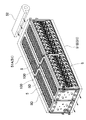
- a power supply device includes a plurality of battery cells 91 having a rectangular outer shape, a plurality of separators 92, a pair of bind bars 95, a pair of end plates 94, It has.
- Each separator 92 is interposed between adjacent battery cells 91.
- a battery stack 99 is formed by alternately stacking a plurality of battery cells 91 and a plurality of separators 92. Both end faces of the battery stack 99 in the stacking direction of the battery cells 91 are covered with respective end plates 94.
- Each bind bar 95 extends in the stacking direction of the battery cells 91 and is fixed to end plates 94 positioned at both ends of the battery stack 99.
- a typical battery cell includes a conductive outer can, positive and negative electrode plates, and an electrolytic solution. Since the positive and negative electrode plates and the electrolytic solution are enclosed in the conductive outer can, the outer can has an electric potential. For this reason, it is necessary to insulate the surface of the outer can in order to prevent unintentional conduction through condensation with the adjacent secondary battery or corrosion of the outer can. For example, since the bottom surface side of the battery cell is a portion into which condensed water droplets flow, it is necessary to insulate the bottom surfaces of the outer cans.
- a fastening member like the bind bar which bent the metal plate may be used, but when a fastening member is metal, There has been a demand for a structure that does not allow the outer cans to conduct through the fastening member.
- an insulating structure for example, a structure in which the surface of an outer can is covered with an insulating sheet made of resin such as PET (for example, see Patent Documents 1 and 2).
- an insulating sheet made of resin such as PET
- a shrink tube that can be coated in close contact with the surface of the outer can by heat shrinkage is employed as such an insulating sheet.
- the insulating sheet must be coated on each battery cell in advance. Therefore, such a configuration has problems such as reduced workability and increased manufacturing costs.
- An object of the present invention is to provide a power supply device capable of insulating the surface of a battery cell at low cost, a power supply system including the power supply device, and a separator for the battery cell. Furthermore, another object of the present invention is to provide a power supply device capable of effectively preventing a short circuit through dew condensation water while maintaining the insulation state between the battery cell and the fastening member while simplifying the insulation structure between the battery cells. It is providing the power supply system provided with this power supply device, and the separator for battery cells.
- Still another object of the present invention is to provide a power supply device that can be produced efficiently by simplifying assembly when a plurality of battery cells are stacked in a manufacturing process of the power supply device, a power supply system including the power supply device, and a battery.
- the object is to provide a separator for cells.
- a battery is connected to each of the plurality of battery cells 1 having a rectangular outer shape with a thickness smaller than the width of the main surface 1X, and the plurality of battery cells 1.
- a battery laminate 9 formed by laminating a plurality of separators 2 and 62 that at least partially cover the surface of the cell 1 and battery cells 1 that are covered with the separators 2 and 62 with the principal surfaces 1X facing each other.
- the fastening member 3 to be fastened is provided.
- the separators 2 and 62 are made of an insulating member that is elastically deformed, and further, a main body plate portion 20 that covers the main surface 1X of the battery cell 1 that is disposed to face the first surface of the main body plate portion 20.
- the battery cell is provided at the bottom part on the 20A side, and is provided at the top part on the first surface 20A side of the main body plate part 20 and the box-shaped covering part 21 for inserting and covering the bottom surface part 1T of the battery cell 1.
- a corner covering portion 22 covering the corner portion 1S of the top surface portion.
- the bottom surface of the battery cell is covered with the box-shaped covering portion of the spacer, so that even if moisture such as condensation has accumulated on the bottom surface, The advantage that a short circuit can be effectively prevented is obtained.
- the battery cell can be easily and easily fixed by inserting the bottom surface portion of the battery cell into the box-shaped covering portion of the separator and covering and holding the corner portion of the top surface portion of the battery cell with the corner covering portion.
- the battery cell surface can be insulated by covering it with a separator.
- the bottom surface portion 1T of the battery cell 1 is inserted into the box-shaped covering portion 21 of the separators 2 and 62, and the corner portion 1S of the top surface portion of the battery cell 1 is covered with the corner covering portion 22.
- the battery cell unit 10 can be formed by stacking a plurality of the battery cell units 10 and 60 by forming the battery cell units 10 and 60 with the separators 2 and 62 mounted at fixed positions of the battery cell 1.
- the battery cell can be easily and reliably attached.
- a battery cell unit having a separator mounted at a fixed position can be formed.
- it can be stored, transported, and assembled in units of battery cell units in which separators are attached to the battery cells, and work can be performed safely and securely while using the shrinkless battery cells.
- assembly work can be simplified and productivity can be improved.
- the separator 2 further includes a side wall 23 that forms the side surfaces of the box-shaped covering portion 21 and the corner covering portion 22 on the side surface on the first surface 20A side of the main body plate portion 20.
- a notch 24 can be formed in the middle.
- the side surface of the battery cell to which the separator is connected is covered with the side wall and insulated, and a notch is formed in the middle portion of the side wall.
- the main body plate part of the separator can be easily bent, and the battery cell can be easily set on the separator.
- the separator is inserted into the box-shaped cover portion with the bottom surface portion of the battery cell in a state where the main body plate portion is bent to the opposite side to the first surface at the side wall notch, and then the main body plate portion is returned to the original posture.
- the battery cell can be easily and easily set at the fixed position of the separator by guiding the corner of the top surface of the battery cell to the corner covering portion while being restored.
- the separator 2 has a first air blowing groove 30 ⁇ / b> A for forming an air passage 8 between the battery cell 1 stacked on the first surface 20 ⁇ / b> A side of the main body plate portion 20 and the main body plate portion 20. Can be formed on the first surface 20 ⁇ / b> A of the main body plate portion 20, and both end openings of the first air blowing groove 30 ⁇ / b> A can be communicated with the notch 24.
- the separator 2 has an air passage between the battery cell 1 and the main body plate portion 20 stacked on the second surface 20B side which is the surface opposite to the first surface 20A of the main body plate portion 20. 8 can be formed on the second surface 20B of the main body plate portion 20, and both end openings of the second air blowing groove 30B can be opened along the side wall 23.
- an air passage for cooling the battery cells stacked on the second surface side of the main body plate portion is provided on the second surface side of the main body plate portion along the side wall, thereby cooling the battery cells.
- the air path of the cooling gas to be efficiently secured.
- the main body plate portion 20 includes a reverse extension side wall 25 extending toward the second surface 20B along the notch 24, and the separator is disposed adjacent to the reverse extension side wall 25. It can be formed into a shape that fits into the two notches 24.
- the separators can be mechanically connected to each other by fitting the separators connected to the battery cells with the reversely extended side walls and the notches in a stacked state. Thereby, almost the entire side surface of the battery cell can be covered.
- the side wall 23 can include the vertical wall 31 along the vertical direction
- the reverse extension side wall 25 can include the vertical wall 32 along the vertical direction.
- the fastening member 3 includes a pair of end plates 4 disposed on both end surfaces of the battery stack 9 and a bind bar 5 coupled to both ends of the pair of end plates 4.
- 5 includes a side plate portion 5X that covers the side surface of the battery stack 9, and a side surface plate portion 5X is provided with a blower opening 5D that faces the opening of the air passage 8, and is formed in the side wall 23 and the reverse extension side wall 25.
- the vertical walls 31 and 32 can be disposed in the blower opening 5D.
- the creeping distance between the battery cell and the bind bar is extended by arranging the vertical wall provided on the side wall and the reversely extended side wall in the blower opening opened on the bind bar arranged on the side surface of the battery stack.
- an unintended short circuit between the battery cell and the bind bar due to condensation or the like can be effectively prevented.
- the cooling gas can flow into the opening of the air passage along the vertical wall, and the air passage to the air passage can be secured. .
- the side wall 23 and the reverse extension side wall 25 are provided with two rows of vertical walls 31 and 32 at positions facing each other, and the two vertical walls 31 and 32 facing each other are continuous vertically.
- a groove 34 can be formed.
- the bind bar 5 includes a connecting bar 5F that reinforces the side plate portion 5X in which the blower opening 5D is opened, and a plurality of blower openings 5D are formed in the side plate portion 5X via the connecting bar 5F. It can be inserted into the longitudinal groove 34.
- connection bar is inserted into the vertical groove formed by the vertical wall formed on the side wall and the reversely extended side wall, thereby causing condensation. It is possible to effectively prevent an unintended short circuit between the battery cell and the connection bar due to the above. Further, by arranging the connecting bar in the vertical groove, the cooling gas forcedly blown is prevented from being affected by the connecting bar, and effective cooling can be realized.
- the power supply apparatus further includes an insulating cover film 63 that partially covers the battery cell 1, and the cover film 63 is formed by at least the box-shaped covering portion 21 in the battery cell 1 covered with the separator 62. It can extend from the surface of the battery cell 1 covered to the surface of the battery cell 1 covered by the corner covering portion 22.
- the battery cell is covered with the box-shaped covering portion of the spacer, the corner of the top surface portion of the battery cell is covered with the corner-covering portion, and further, the battery cell covered with the box-shaped covering portion Since the battery cell is covered with the insulating cover film from the surface of the battery cell to the surface of the battery cell covered with the corner covering portion, the region from the bottom surface portion to the top surface portion of the battery cell can be covered in an insulating state. It is possible to prevent unintentional energization reliably by preventing a person or metal from directly contacting the surface.
- the power supply device of the present invention can be arranged in a sideways posture in which both side surfaces of the battery stack 9 are directed in the vertical direction.
- the battery cell is covered with the box-shaped covering portion of the spacer, and the corners of the top surface portion of the battery cell are covered with the corner covering portion, so that both side surfaces of the battery stack are directed vertically. Even in a state of being placed in a lying position, moisture caused by condensation or the like can flow down along the inner surfaces of the box-shaped covering portion and the corner covering portion, thereby effectively preventing a short circuit due to condensed water.
- the main body plate portion of the separator is provided with a side wall and a reverse extension side wall, and a vertical wall is provided on the side wall and the reverse extension side wall, the vertical disposed on the lower surface side of the power supply device disposed in a lying position.
- the power supply system of the present invention can include a plurality of any of the power supply devices 100 described above, and includes at least a pair of power supply devices 100.
- Each power supply device 100 has both side surfaces of the battery stack 9 in the vertical direction. It is possible to arrange the pair of power supply devices 100 in such a manner that the bottom surfaces of the battery stacks 9 face each other, and the top surfaces of the battery cells 1 can be arranged in the left and right opposite directions. .
- the pair of power supply devices are arranged in such a posture that the bottom surfaces of the battery stack are opposed to each other while the both sides of the battery stack are arranged in a lying position with the vertical direction facing each other. While arranging in a space-saving manner, the top surfaces of the battery cells can be arranged in opposite directions to the left and right so that the electrode terminals of each battery cell can be efficiently wired.
- the separator of the present invention is a separator for insulating the surface of each battery cell 1 used in a power supply device in which a plurality of battery cells 1 having a rectangular outer shape with a thickness smaller than the width of the main surface 1X are stacked.
- the main body plate portion 20 that covers the main surface 1X of the battery cell 1 that is disposed to face the bottom surface portion 1T of the battery cell 1 is provided on the bottom portion of the main body plate portion 20 on the first surface 20A side.
- a box-shaped covering portion 21 that covers and covers the corner portion 1S of the top surface portion of the battery cell 1 that is provided on the top portion of the main body plate portion 20 on the first surface 20A side.
- And can be made of an insulating member that is elastically deformed.
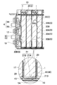
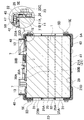
- FIG. 3 is a partially enlarged III-III cross-sectional view of the power supply device shown in FIG. 1.
- FIG. 4 is a partially enlarged IV-IV cross-sectional view of the power supply device shown in FIG. 1.
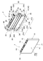
- FIG. 7 is a rear perspective view of the battery cell unit shown in FIG. 6.
- FIG. 6 is an exploded sectional view showing a state in which the battery cell units shown in FIG. 5 are stacked.
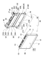
- FIG. 1 is a perspective view of a power supply system according to an embodiment of the present invention. It is a cross-sectional perspective view of the power supply system shown in FIG. It is a disassembled perspective view of the conventional power supply device.
- 1 to 4 show a power supply device 100 according to an embodiment of the present invention.
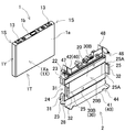
- 1 to 4 includes a plurality of battery cells 1 having a rectangular outer shape, and a separator 2 connected to each of the plurality of battery cells 1 to at least partially cover the surface of the battery cell 1.
- the power supply apparatus shown in FIGS. 1 to 4 has a battery cell unit 10 in which a separator 2 is mounted on a battery cell 1, and a plurality of battery cell units 10 are stacked to form a battery stack.
- a body 9 is formed.
- the battery cell 1 is a prismatic battery in which the outer shape of the main surface 1X, which is a wide surface, is a quadrangle, and is thinner than the width of the main surface 1X. Furthermore, the battery cell 1 is a secondary battery that can be charged and discharged, and is a lithium ion secondary battery.
- the power supply device of the present invention does not specify a battery cell as a lithium ion secondary battery, but can be charged / discharged, for example, a nonaqueous electrolyte secondary battery other than a lithium ion secondary battery or a nickel water battery cell. Etc. can also be used.
- the battery cell 1 is one in which an electrode body in which positive and negative electrode plates are laminated is housed in an outer can 1a, filled with an electrolyte, and hermetically sealed.
- the outer can 1 a is formed in a square cylindrical shape that closes the bottom, and the upper opening is airtightly closed with a metal plate sealing plate 1 b.
- the outer can 1a is manufactured by deep drawing a metal plate such as aluminum or aluminum alloy.
- the sealing plate 1b is made of a metal plate such as aluminum or aluminum alloy in the same manner as the outer can 1a.
- the sealing plate 1b is inserted into the opening of the outer can 1a, irradiates a laser beam to the boundary between the outer periphery of the sealing plate 1b and the inner periphery of the outer can 1a, and laser-welds the sealing plate 1b to the outer can 1a. Airtightly fixed.
- the battery cell 1 has positive and negative electrode terminals 13 protruding and fixed at both ends of the sealing plate 1b.
- the positive and negative electrode terminals 13 are connected to built-in positive and negative electrode plates (not shown), respectively.
- the position of the electrode terminal 13 fixed to the top surface of the battery cell 1 is a position where the positive electrode and the negative electrode are symmetrical.
- the battery cells 1 can be reversed and stacked, and the positive and negative electrode terminals 13 that are adjacent to each other can be connected by the bus bar 17 made of a metal plate and connected in series.
- the power supply device that connects the battery cells 1 in series can increase the output voltage to increase the output.
- the power supply device can also connect battery cells in parallel and in series.
- the battery cell 1 which is a square battery, is configured with a battery cell unit 10 with a separator 2 mounted thereon. Further, a plurality of battery cell units 10 are stacked in the thickness direction of the battery cell 1 to form a battery stack 9.
- the vertical direction of the battery cell 1 is specified in FIG.
- the side surface 1Y of the battery cell 1 is a state in which a plurality of battery cell units 10 are stacked to form a battery stack 9 in a posture in which the main surface 1X that is a wide surface is opposed to each other. It means a narrow surface to be arranged.
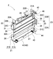
- the separator 2 is made of an insulating member, and is connected to each battery cell 1 as shown in FIGS. 3 to 9 to partially cover and insulate the surface of the battery cell 1. Further, the separator 2 holds adjacent battery cells 1 at a constant interval while insulating the battery cells 1 stacked on each other.
- a separator 2 is manufactured by molding an insulating material such as plastic.
- the separator 2 is a soft material having elasticity, and is made of a plastic material such as PP or silicon.
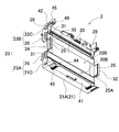
- the separator 2 is formed on the main body plate portion 20 that covers the main surface 1X of the battery cells 1 that are arranged to face each other, and on the bottom portion of the main body plate portion 20 on the first surface 20A side.
- a box-shaped covering portion 21 provided to insert and cover the bottom surface portion 1T of the battery cell 1 and a top portion of the main body plate portion 20 on the first surface 20A side.
- a corner covering portion 22 that covers the portion 1S.
- the separator 2 covers one main surface 1X of the battery cell 1 constituting one battery cell unit 10 with the main body plate portion 20, and the box-shaped covering portion 21 covers the bottom surface portion 1T of the battery cell 1 with a corner angle.
- the covering portion 22 holds the corner portion 1S of the top surface portion of the battery cell 1 to hold the battery cell 1 in a fixed position.
- the main body plate portion 20 has a plate shape having a size and shape substantially equal to the main surface 1 ⁇ / b> X of the battery cell 1.
- the main body plate portion 20 has the side on which the battery cells 1 constituting the battery cell unit 10 are disposed as the first surface 20A, and the box-shaped covering portion 21 is provided on the bottom portion on the first surface 20A side, and both corners of the top portion.
- the corner covering portion 22 is provided in the portion.
- the main body plate portion 20 has the surface opposite to the first surface 20A as the second surface 20B, and the second surface 20B is formed on the main surface 1X of the battery cell 1 constituting the battery cell unit 10 laminated adjacently. It is in contact.
- the main body plate portion 20 is set on the separator 2 to cover the first main surface 1Xa of the battery cell 1 constituting the battery cell unit 10 in contact with the first surface 20A, and is laminated adjacently.
- the second main surface 1Xb of the battery cell 1 constituting the battery cell unit 10 is covered with the second surface 20B.
- the box-shaped covering portion 21 is formed in a box shape into which the bottom surface portion of the battery cell 1 can be inserted.
- the box-shaped covering portion 21 shown in FIGS. 6 to 9 has a box shape with an upper opening so that the bottom surface of the rectangular battery cell 1 can be inserted and covered over the entire bottom surface.
- the box-shaped covering portion 21 is formed along the lower end edge of the main body plate portion 20, and is raised upward from the bottom surface covering portion 21A protruding toward the first surface 20A and the front end edge of the bottom surface covering portion 21A.
- a front surface covering portion 21B, a main body plate portion 20, a bottom surface covering portion 21A, and a side surface covering portion 21C formed by connecting both side edges of the front surface covering portion 21B.
- the box-shaped covering portion 21 is provided integrally with the main body plate portion 20.
- the box-shaped covering portion 21 covers the bottom surface of the battery cell 1 inserted along the first surface 20A of the main body plate portion 20 with the bottom surface covering portion 21A, and the bottom portion of the second main surface 1Xb of the battery cell 1 Is covered with the front surface covering portion 21B, and the bottom portions of both side surfaces 1Y are covered with the side surface covering portion 21C.
- the box-shaped covering portion 21 having this structure covers the entire bottom surface portion 1T of the battery cell 1 inserted therein without a gap. Therefore, even if water droplets such as condensed water flow into the bottom surface side of the battery cell 1, the entire bottom surface portion 1 ⁇ / b> T of the battery cell 1 is covered with the box-shaped covering portion 21, so that a short circuit caused by the water droplets can be prevented. It can be surely prevented.
- the box-shaped covering portion 21 shown in FIG. 3 and FIG. 6 is formed with step protrusions 21D protruding toward the inner surface at both ends of the inner surface of the bottom surface covering portion 21A.
- a gap 29 is formed between the bottom surface of the battery cell 1 and the inner surface of the bottom surface covering portion 21 ⁇ / b> A in a state in which the bottom surface of 1 is brought into contact. This structure prevents water flowing into the box-shaped covering portion 21 from flowing out into the gap 29 and temporarily storing it, thereby preventing it from flowing out.
- the corner covering portion 22 has a structure capable of guiding the corner portion 1S of the top surface portion of the rectangular battery cell 1 and locking the corner portion 1S.
- the corner covering portion 22 shown in FIGS. 6 to 9 has a concave shape in which one side surface is removed from the box-shaped opening so that the corner 1S of the rectangular battery cell 1 can be fitted.
- the corner covering portion 22 is formed on both side edges of the upper end edge of the main body plate portion 20, and projects from the top surface covering portion 22 ⁇ / b> A protruding toward the first surface 20 ⁇ / b> A and from the leading edge of the top surface covering portion 22 ⁇ / b> A.
- a side surface covering portion 22C formed by connecting side edges of the main body plate portion 20, the top surface covering portion 22A, and the front surface covering portion 22B.
- the corner covering portion 22 is provided integrally with the main body plate portion 20.
- the corner covering portion 22 covers both ends of the top surface (sealing plate 1b) of the battery cell 1 in which the bottom surface portion 1T is inserted into the box-shaped covering portion 21 with the top surface covering portion 22A. Both sides of the top portion of the second main surface 1Xb are covered with the front surface covering portion 22B, and the top portions of the both side surfaces 1Y are covered with the side surface covering portion 22C.
- the corner covering portion 22 having this structure is formed by turning up the front covering portion 22B that is elastically deformed when guiding the corner portion 1S of the battery cell 1 (see arrow C in FIG. 10). To facilitate the insertion of the corner 1S of the battery cell 1.
- the inner surfaces of the top surface covering portion 22A, the front surface covering portion 22B, and the side surface covering portion 22C are on the surface of the corner portion 1S of the battery cell 1.
- the corner portion 1S of the battery cell 1 can be positioned by contacting.
- the corner covering portion 22 shown in FIGS. 4 and 8 protrudes from the inner surface of the top surface covering portion 22A and is provided with a positioning protrusion 22D.
- the separator 2 is configured such that the positioning protrusions 22 ⁇ / b> D are brought into contact with both side portions of the top surface of the battery cell 1 so that the battery cell 1 can be disposed at a fixed position of the separator 2.
- the separator 2 includes a side wall 23 that forms side surfaces of the box-shaped covering portion 21 and the corner covering portion 22 on the side surface of the main body plate portion 20 on the first surface 20A side.
- the side wall 23 shown in FIGS. 5 to 9 includes a lower side wall 23 A including the side surface of the box-shaped covering portion 21 and an upper side wall 23 B including the side surface of the corner covering portion 22.
- the side wall 23 in the figure has a notch 24 formed in the middle, and the notch 24 divides the lower side wall 23A and the upper side wall 23B vertically.
- the lower side wall 23 ⁇ / b> A includes a side surface covering portion 21 ⁇ / b> C of the box-shaped covering portion 21 and a vertical side wall 26 extending upward from the side surface covering portion 21 ⁇ / b> C, and the battery facing the side surface covering portion 21 ⁇ / b> C and the vertical side wall 26.
- the bottom of the side surface 1Y of the cell 1 is covered.
- the upper side wall 23B includes a side surface covering portion 22C of the corner covering portion 22 and a vertical side wall 26 extending downward from the side surface covering portion 22C.
- the battery facing the side surface covering portion 22C and the vertical side wall 26 is opposed to the upper side wall 23B.
- the top of the side surface 1Y of the cell 1 is covered.
- the central portion of the side surface 1Y of the battery cell 1 is not covered with the side wall 23 and is exposed to the outside when the separator 2 is mounted as shown in FIG.
- the vertical side walls 26 of the lower side wall 23A and the upper side wall 23B have one side edge connected to the main body plate portion 20 and the other side edge positioned in front of the second main surface 1Xb of the battery cell 1.
- the lateral width is made smaller than the thickness of the battery cell 1. That is, in the lower side wall 23A and the upper side wall 23B shown in the drawing, the width of the vertical side wall 26 is narrower than the width of the side surface covering portions 21C and 22C, and the side wall of the vertical side wall 26 on the second main surface 1Xb side is formed.
- An exposed cut portion 27 is provided, and the corner portion of the outer can 1a of the battery cell 1 is exposed at this portion.
- the exposed cut portion 27 of the vertical side wall 26 is provided with openings at both ends of the air passage 8 formed between the separator 2 and the main body plate portion 20 of the separator 2 that face each other.
- the side wall 23 secures a blowing path to the air path 8 by exposing the corner portion of the outer can 1 a along the exposed cut portion 27 of the vertical side wall 26.
- the separator 2 is provided with a side wall 23 on the side surface of the main body plate portion 20 on the first surface 20A side so that the side surface 1Y of the battery cell 1 to which the separator 2 is mounted is covered with the side wall 23 and insulated.
- the notch 24 in the middle portion of the main body plate 20, the main body plate portion 20 is easily bent at the portion of the notch 24 and is easily set in the battery cell 1.
- the separator 2 is formed by bending the upper portion of the main body plate portion 20 toward the second surface 20 ⁇ / b> B (see arrow A) at the notch 24 of the side wall 23.
- the battery cell 1 can be set at a fixed position of the separator 2 by guiding the corner 1 ⁇ / b> S of 1.
- the front cover 22B that is elastically deformed is turned outward (see arrow C) to widen the opening of the recess, thereby The corner 1S of the cell 1 can be easily inserted.
- the side wall 23 shown in the figure forms a convex portion 28 protruding outward on the surface of the side surface covering portions 21C and 22C.
- the convex portion 28 has a flat front end surface, and can be positioned by contacting the inner side surface of the bind bar 5 arranged on the side surface of the battery stack 9.
- the separator 2 is configured so that the inner surface of the bind bar 5 is brought into contact with the front end surface of the convex portion 28 so that the distance from the bind bar 5 can be maintained at a predetermined distance.
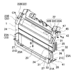
- the separator 2 includes a reverse extension side wall 25 that extends along the notch 24 of the side wall 23 toward the second surface 20 ⁇ / b> B side of the main body plate portion 20.
- the reverse extension side wall 25 is a plate-like shape that protrudes toward the second surface 20B of the main body plate portion 20, and is formed in a shape that fits with the notch 24 of the separator 2 that is disposed adjacently as shown in FIG. ing.
- the reverse extension side wall 25 shown in FIGS. 7 and 9 forms a step recess 25A along both the upper and lower ends on the side facing the side surface 1Y of the battery cell 1, and the vertical side wall 26 of the facing separator 2 is formed.
- the leading edges are guided to the step recess 25A so that they can be fitted to each other.
- the reverse extension side wall 25 has a wrap structure in which the leading edge of the vertical side wall 26 and the stepped recess 25A are stacked on each other, thereby effectively preventing condensed water and the like from passing through this portion.
- the inner surface of the side wall 23 and the inner surface of the reverse extension side wall 25 are arranged on the same plane so that they can be arranged along the side surface 1Y of the battery cell 1.
- the separator 2 including the reverse extension side wall 25 is mechanically formed by fitting the opposing separators with the reverse extension side wall 25 and the notch 24 in a state where the battery cell units 10 adjacent to each other are stacked. Can be linked. Therefore, in the process of laminating the plurality of battery cell units 10, the battery cell units 10 can be quickly laminated in the correct posture without making the wrong orientation. Further, since the exposed portion of the battery cell 1 generated in the notch 24 portion of the separator 2 is covered with the reversely extended side wall 25 of the separator 2 of the adjacent battery cell unit 10, almost the entire side surface 1Y of the battery cell 1 is covered. be able to. Accordingly, both side surfaces of the battery stack 9 are almost entirely covered with the side wall 23 and the reverse extension side wall 25 of the separator 2 to prevent the surface of the outer can 1a having potential from being exposed to the outside. Can be improved.
- the separator 2 is provided with a groove-like recess on the surface of the main body plate portion 20 in order to blow the cooling gas along the surface of the battery cell 1 in close contact with the surface of the battery cell 1.
- An air passage 8 is formed between the battery cell surfaces.
- the separator 2 shown in FIGS. 3 to 5, 7, and 8 is provided with air blowing grooves 30 that extend to both side edges on the surface facing the battery cell 1, and the air blowing grooves 30 and the main surface of the battery cell 1.
- a gap formed between 1X is defined as an air passage 8.
- the air passage 8 is provided in the horizontal direction so as to open on the left and right side surfaces of the battery stack 9 as shown in FIGS. 1 and 6 to 9.
- a plurality of rows of air blowing grooves 30 are provided on both surfaces of the main body plate portion 20, and air paths 8 are formed on both surfaces of the main body plate portion 20.
- the air path 8 formed on both surfaces of the main body plate portion 20 is linear, and a plurality of rows are provided in parallel to each other. This structure has an advantage that the battery cell 1 arranged facing both surfaces can be effectively cooled by the air passages 8 formed on both surfaces of the main body plate portion 20.
- the separator can be provided with a ventilation groove only on one side, and an air path can be provided between the battery cell and the main body plate portion.
- this separator can be provided with an air passage only in a central portion facing the central portion of the battery cell.
- the separator 2 shown in FIGS. 6, 8, and 11 has a first air groove 30 ⁇ / b> A formed on the first surface 20 ⁇ / b> A of the main body plate portion 20, and the first air groove 30 ⁇ / b> A causes the first air groove 30 ⁇ / b> A to
- An air path 8 is formed between the battery cell 1 and the main body plate portion 20 stacked on the one surface 20A side.
- two rows of first air blowing grooves 30 ⁇ / b> A are formed in the central portion of the first surface 20 ⁇ / b> A of the main body plate portion 20, and both end openings of the first air blowing grooves 30 ⁇ / b> A communicate with the notches 24. .
- an air passage 8 for cooling the battery cell 1 stacked on the first surface 20A side of the main body plate portion 20 is provided in communication with the notch 24 of the side wall 23 so that a cooling gas passage is provided in the battery. It can be secured on the left and right side surfaces of the laminate 9.
- positioned by fitting to the notch 24 has adjusted the protrusion amount to the 2nd surface 20B side so that the both-ends opening of 30 A of 1st ventilation grooves may not be obstruct
- the separator 2 shown in FIG.7, FIG.9 and FIG.11 has formed the 2nd ventilation groove 30B in the 2nd surface 20B of the main body plate part 20, and the main body plate part 20 by this 2nd ventilation groove 30B.
- An air passage 8 is formed between the battery cell 1 and the main body plate portion 20 stacked on the second surface 20B side.
- the separator 2 in the figure forms a second air blowing groove 30 ⁇ / b> B in one row above and below the second surface 20 ⁇ / b> B of the main body plate portion 20.
- the separator 2 is the back surface of the first air blowing groove 30A formed on the first surface 20A, and forms the second air blowing groove 30B along the top and bottom of the ridge protruding to the second surface 20B side.
- Openings at both ends of the two air blowing grooves 30 ⁇ / b> B are opened along the side wall 23. Further, in the separator 2 shown in the drawing, both end openings of the second air blowing groove 30B are arranged along the exposed cut portion 27 provided on the side wall 23 of the separator 2 stacked facing each other. Thereby, both ends opening of the 2nd ventilation groove
- the air passages 8 formed on both surfaces of the main body plate part 20 blow the cooling gas, and as shown in FIG. 4, the air blowing openings 5 ⁇ / b> D opened on the bind bar 5 arranged on the side surface of the battery stack 9. It is arrange
- the cooling gas forcedly blown to the battery cell 1 flows into the air passage 8 from the air blowing opening 5D opened in one bind bar 5, cools the battery cell, passes through the air passage 8, and then the other bind bar.
- the separator 2 includes vertical walls 31 and 32 along the longitudinal direction of the side wall 23 and the reversely extended side wall 25 disposed on the side surface 1Y of the battery cell 1.
- the side wall 23 shown in FIGS. 5 to 9 is provided with two rows of vertical walls 31 projecting outward along both side edges of the vertical side wall 26 extended from the side surface covering portions 21C and 22C.
- the side wall 23 forms two rows of vertical walls 31 parallel to each other.
- the vertical wall 31 formed along the exposed cut portion 27 is provided with a curved portion 31 ⁇ / b> A along the boundary portion with the side surface covering portions 21 ⁇ / b> C and 22 ⁇ / b> C.
- the creepage distance between the inner surface side and the outer surface side of the side wall 23 is increased over the entire region 27.
- the curved portion 31A shown in the figure is reinforced by providing ribs 33 parallel to the side walls 23 along the inner surface.
- the vertical wall 31 formed along the exposed cut portion 27 of the side wall 23 is erected along both end openings of the second air blowing groove 30 ⁇ / b> B formed between the battery cell 1 and the battery cell 1 disposed to face each other. Therefore, the cooling gas blown from the outside can efficiently flow into the air path 8 along the vertical wall 31.
- the reverse extension side wall 25 shown in FIGS. 5 to 9 is provided with two rows of vertical walls 32 in parallel along the vertical direction. As shown in FIG. 5, two rows of vertical walls 32 formed on the reverse extension side wall 25 are formed by stacking adjacent battery cell units 10 and fitting one reverse extension side wall 25 into the other notch 24. In such a state, it is formed so as to be positioned on the extension line of the two vertical walls 32 formed on the side wall 23. Since the vertical wall 32 formed along the front end edge of the reverse extension side wall 25 is erected along the both end openings of the first air blowing groove 30A, the cooling gas blown from the outside is sent along the vertical wall 32. Can flow into the air passage 8 efficiently.
- the vertical walls 31 and 32 formed on the side wall 23 and the reversely extended side wall 25 are blower openings 5 ⁇ / b> D opened on the side plate portion 5 ⁇ / b> X of the bind bar 5 arranged on the side surface of the battery stack 9. Placed in. Thereby, the creeping distance between the battery cell 1 and the bind bar 5 is extended to prevent a short circuit between the battery cell 1 and the bind bar 5 due to condensation or the like.
- the vertical walls 31 and 32 shown in the figure adjust the protruding amount so that the front end edges thereof are located on substantially the same plane as the outer surface of the bind bar 5. However, the vertical wall can also have its tip edge protruding beyond the outer surface of the bind bar. Further, the structure in which the vertical walls 31 and 32 are arranged in the air blowing opening 5 ⁇ / b> D of the bind bar 5 can smoothly flow the cooling gas into the air passage 8 opened along the vertical walls 31 and 32.
- the side wall 23 and the reversely extended side wall 25 shown in FIG. 12 are formed by two rows of vertical walls 31 and 32 arranged at positions facing each other to form a continuous vertical groove 34.
- the bind bar 5 disposed on the side surface of the battery stack 9 includes a connection bar 5F in the air blowing opening 5D, and the connection bar 5F is inserted into the vertical groove 34.
- the connection bar 5F of the bind bar 5 is inserted into the vertical groove 34 formed by the vertical walls 31 and 32 provided on the side wall 23 and the reverse extension side wall 25, whereby the battery cell 1 and the connection bar due to condensation or the like are inserted. A short circuit with 5F can be effectively prevented.
- the separator 2 shown in the figure is a positioning connection portion that protrudes in the stacking direction of the battery cells 1 along the outer periphery of the main body plate portion 20 so that the battery cell units 10 stacked adjacent to each other can be connected to a fixed position. 40 is provided.
- the positioning connecting portion 40 shown in the figure includes a bottom surface connecting portion 41 that positions both corner portions on the bottom surface side of the separator 2 and a corner connecting portion 42 that positions both corner portions on the top surface side of the separator 2.
- the bottom surface connecting portion 41 is formed to protrude toward the second surface 20 ⁇ / b> B along the lower end edge of the main body plate portion 20.
- the bottom surface connection portion 41 is a plate extending in the stacking direction of the battery cells 1, and is provided over the entire bottom surface of the box-shaped covering portion 21.
- the bottom surface connecting portion 41 is stacked on the bottom surface of the box-shaped covering portion 21 of the battery cell unit 10 stacked adjacent to each other, and is connected to the outside of the box-shaped covering portion 21 of the opposing separator 2.
- the bottom surface connecting part 41 shown in the figure has a structure in which both side parts are raised along both corners of the box-shaped covering part 21 and are connected while positioning the left and right directions of the box-shaped covering part 21 by this rising part. It is said.
- the bottom surface portion of the box-shaped covering portion 21 into a double wall structure with the bottom surface connecting portion 41, either the box-shaped covering portion 21 or the bottom surface connecting portion 41 is deteriorated due to deterioration over time or vibration. Even if it breaks, conduction to the bind bar 5 due to condensed water or the like can be effectively prevented.
- the bottom surface connecting portion may be configured to cover only both sides of the bottom surface.
- the bottom surface connecting portion is formed to face a portion that comes into contact with the lower end bent portion of the bind bar.
- the bottom surface connecting portion 41 shown in FIGS. 3 to 7 includes a ridge 43 that contacts and positions the lower end bent portion 5 A of the bind bar 5.
- the bottom surface connecting portion 41 shown in the figure is provided with a ridge 43 extending in the stacking direction of the battery cells 1 at a portion facing the lower end bent portion 5 ⁇ / b> A of the bind bar 5.
- the protrusion 43 connects the protrusions 43 of the separators 2 adjacent to each other in a straight line and extends in the extending direction of the lower end bent portion 5A of the bind bar 5.
- a row of connecting ridges is formed.
- the protrusion 43 can be positioned by bringing the inner surface of the lower end bent portion 5 ⁇ / b> A into contact with the tip surface of the protrusion 43 in a state where the bind bar 5 is disposed on the side surface of the battery stack 9.
- the bottom surface connecting portion 41 shown in FIGS. 8 and 9 is provided with a notch 44 at the tip portion facing the ridge 43, and the ridge 43 of the opposing separator 2 is fitted into the notch 44 for positioning. It has a structure that can be done.
- the ridges 43 shown in FIGS. 8 and 9 are provided so as to extend from the bottom surface connecting portion 41 to a part of the box-shaped covering portion 21, and the bottom surface connecting portion 41 is notched at the bottom surface of the box-shaped covering portion 21. It is connected to the portion 44 with a fitting structure.
- the corner connecting portion 42 is formed so as to protrude toward the second surface 20B along both top corners of the main body plate portion 20.
- the corner connecting portion 42 is extended in the stacking direction of the battery cells 1 as a plate shape having a substantially L-shaped vertical cross section.
- the corner connecting portion 42 is stacked along the top surface covering portion 22 ⁇ / b> A of the corner covering portion 22 and the upper end portion of the side covering portion 22 ⁇ / b> C and connected to the outside of the corner covering portion 22.
- the corner connecting portion 42 having a substantially L-shaped vertical cross section is connected to the corner covering portion 22 while positioning the vertical direction in the horizontal portion and positioning the left and right direction in the vertical portion.
- corner connecting portion 42 shown in FIGS. 8 and 9 has a fitting notch 46 at the tip of the horizontal portion, and the fitting protrusion formed on the surface of the top cover portion 22A of the opposing separator 2.
- the portion 47 is inserted to be positioned with respect to each other.
- the corner connecting portion 42 shown in FIGS. 3 to 7 is provided with a ridge 45 that contacts and positions the upper end bent portion 5B of the bind bar 5.
- the corner connecting portion 42 shown in the figure is a portion facing the upper end bent portion 5B of the bind bar 5, and a protrusion 45 extending in the stacking direction of the battery cells 1 is provided on the upper surface of the horizontal portion.
- the protrusion 45 connects the protrusions 45 of the separators 2 adjacent to each other in a straight line and extends in the extending direction of the upper end bent portion 5B of the bind bar 5.
- a row of connecting ridges is formed.
- the separator 2 can be positioned by bringing the inner surface of the upper end bent portion 5B of the bind bar 5 into contact with the tip surface of the protrusion 45 in a state where the bind bar 5 is disposed on the side surface of the battery stack 9.
- the separator 2 shown in FIGS. 4 to 9 is provided with standing walls 48 protruding upward along the side edges of the corner covering portion 22 and the corner connecting portion 42 on both sides of the top surface.
- the standing wall 48 partitions and insulates the electrode terminal 13 provided on the top surface of the battery cell 1 and the tip edge of the upper end bent portion 5B of the bind bar 5.
- the structure which provides the standing wall 48 between the front-end edge of the bind bar 5 and the upper surface of the battery cell 1 can effectively prevent an unintended short circuit by increasing the creepage distance in this portion.
- the positioning connecting portion 40 is connected along the bottom surface of the box-shaped covering portion 21 in the state where the battery cell units 10 adjacent to each other are stacked and connected.
- the corner connecting portion 42 is connected along the outer periphery of the corner covering portion 22 and connects the separators 2 stacked adjacent to each other while positioning them vertically and horizontally.
- the bottom surface connection part 41 connected along the bottom surface of the box-shaped covering part 21 is positioned by inserting the protruding strips 43 of the opposing separator 2 into the notch part 44 formed at the tip part.
- the fitting convex portion 47 of the opposing separator 2 is inserted into the fitting notch portion 46 formed at the tip portion of the horizontal portion. Is positioned.
- Battery cell unit 10 As shown in FIG. 5, the separator 2 described above is attached to the battery cell 1 to form a battery cell unit 10.
- the surface of the battery cell 1 is partially covered with the separator 2, and the battery cell unit 10 is stacked in a state in which a plurality of battery cell units 10 are stacked to form the battery stack 9.
- the structure is such that a part of the surface, for example, almost the entire region excluding the electrode terminal 13 can be covered.
- This structure can surely prevent a person or metal from directly contacting the surface of the battery cell 1 having a potential, and can prevent unintended energization. Further, by covering almost the entire surface of the battery cell 1, even when condensed water is generated, it is possible to effectively prevent the surface of the battery cell 1 from being in contact with the exterior member, for example, the bind bar 5, and being energized.
- the battery cell unit 10 is composed of the battery cell 1 and the separator 2, it can be handled in units of the battery cell unit 10 in the manufacturing process, so that the workability can be improved.
- a conventional power supply device a plurality of battery cells and separators interposed between them are alternately stacked to form a battery stack, and the battery stack is fastened in a state of being pressed from both ends.
- the cell and the separator had to be laminated with each other, and this process was troublesome.
- the separator 2 is mounted on the battery cell 1 to form the battery cell unit 10, and the plurality of battery cell units 10 are stacked on each other to form the battery stack 9. Can be improved.
- operations such as storage, transport, and assembly can be performed, and safety can be improved.
- the separator may have a structure shown in FIG.
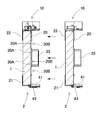
- the separator 62 of the embodiment shown in FIG. 13 omits the side wall 23 and the reverse extension side wall 25 that cover the side surface 1Y of the battery cell 1 with respect to the separator 2 shown in FIG. That is, the separator 62 can have the same configuration as that of the separator 2 described above with reference to FIG. Therefore, in FIG. 13, the same components as those in the embodiment of FIG. 6 are denoted by the same reference numerals, and detailed description thereof is omitted.
- the separator 62 shown in FIG. 13 is formed by inserting the bottom surface portion 1T of the battery cell 1 into the bottom portion on the first surface 20A side of the main body plate portion 20 that covers the main surface 1X of the battery cell 1 disposed to face the separator 62.
- a box-shaped covering portion 21 for covering is provided, and a corner covering portion 22 for covering the corner portion 1S of the top surface portion of the battery cell 1 is provided on the top portion of the main body plate portion 20 on the first surface 20A side.
- the separator 62 has a structure in which a side surface side of the battery cell 1 is exposed without providing a side wall and a reverse extension side wall at a portion facing the intermediate portion of the side surface 1Y of the battery cell 1.
- the separator 62 shown in the figure has both side edges of the main body plate portion 20 as cutting edges.
- this separator 62 does not form a side wall or a reverse extension side wall on the side surface of the main body plate portion 20, it has a feature that a mold for manufacturing the separator 62 can be simplified and mass-produced at low cost. Further, the separator 62 not provided with the side wall can flex the body plate portion 20 freely in the intermediate portion, and can be easily and easily set in the battery cell 1. Similarly to the separator 2 shown in FIG. 10, the separator 62 is also bent or bent on the side opposite to the first surface 20 ⁇ / b> A so that the battery cell 1 is placed inside the box-shaped covering portion 21.
- the bottom surface portion 1T can be easily inserted, and the corner portion 1S of the battery cell 1 is guided inside the corner angle covering portion 22 while the upper portion of the bent or bent main body plate portion 20 is restored to the original posture.
- the battery cell 1 can be set at a fixed position of the separator 62.
- the main body plate part 20 shown in FIG. 13 is provided with an air blowing groove 30 that forms an air passage between the battery cell surfaces facing each other.
- the separator 62 shown in FIG. 13 forms two rows of first air blowing grooves 30A in the central portion of the first surface 20A of the main body plate portion 20, and 1 on the opposite side of the first air blowing groove 30A.
- a second air blowing groove 30B is formed for each row.
- this separator can also form a 1st ventilation groove and a 2nd ventilation groove alternately on both surfaces by making a main-body-part plate part into uneven
- the separator 62 in FIG. 13 has an open side surface, but the outer peripheral surface of the battery cell 1 set here is covered with an insulating cover film 63 so that this portion is exposed from the side surface of the separator 62 to the outside. Preventing exposure.
- the battery cell 1 shown in FIG. 13 has a cover film 63 attached to the upper and lower intermediate portions of a rectangular tube-shaped outer can 1A.
- the cover film 63 is a silicon film, for example, and is formed in a cylindrical shape along the outer peripheral surface of the outer can 1a as shown in FIG.
- the cover film 63 is coated on the surface of the outer can 1a of the battery cell 1 in a close contact state, and an intermediate portion of the outer peripheral surface of the battery cell 1 is coated in an insulated state.
- the cover film 63 prevents the outer can 1a of the battery cell 1 from being exposed to the outside from the side surface of the separator 62. Accordingly, the cover film 63 shown in FIG. 13 has a length that can cover a portion of the side surface 1Y of the battery cell 1 that is not covered by the side surface covering portion 21C of the box-shaped covering portion 21 and the side surface covering portion 22C of the corner covering portion 22. It is said. In other words, in the battery cell 1 covered with the separator 62, the cover film 63 covers at least the surface of the battery cell 1 covered with the box-like covering portion 21 from the surface of the battery cell 1 covered with the corner covering portion 22. It extends over the surface. Thus, by providing the cover film 63 on the battery cell 1, it is possible to reliably insulate the portion exposed from the surface of the separator 62 while simplifying the structure of the separator 62 and manufacturing it at low cost.
- the structure in which the surface of the battery cell 1 is covered with the cover film 63 is higher in manufacturing cost than the structure in which the surface of the battery cell 1 is not covered with a film or the like.
- the cover film 63 shown in the figure does not cover almost the entire battery including the bottom of the outer can of the battery cell, unlike the conventional shrink tube, and covers only the intermediate portion of the outer can 1a.
- the shrink tube it is not necessary to adhere to the surface of the battery cell in a complicated manufacturing process in which the whole is thermally contracted.
- the process of coating the battery cell 1 with a film is simplified, and the bottom surface of the battery cell 1 is separated by the separator 62. By covering the part, it can be reliably insulated.
- the cover film 63 that covers only the intermediate portion of the outer can 1a is formed by, for example, winding a belt-shaped film along the outer peripheral surface of the battery cell 1 without forming it into a cylindrical shape and closely contacting it by heat shrinkage or the like. It can be coated in close contact.
- the cover film 63 can be manufactured easily by covering only the middle part of the outer can without covering the bottom part of the battery cell, which has been difficult to cover with the conventional shrink tube. Cost can be reduced.
- the above separator 62 is also attached to the battery cell 1 covered with the cover film 63 to constitute the battery cell unit 60.
- one main surface 1X of the battery cell 1 is covered with the main body plate portion 20 of the separator 62, and the bottom surface portion 1T of the battery cell 1 is covered with the box-shaped covering portion 21, so that the top surface portion The corner 1 ⁇ / b> S is covered with the corner cover 22.
- a cover film 63 is coated on the surface of the battery cell 1 not covered with the separator 62 and on the other main surface 1X and side surface 1Y of the battery cell 1. For this reason, since almost the entire surface of the battery cell unit 60 excluding the top surface portion of the battery cell 1 is coated in an insulating state, the safety at the time of operations such as storage, transportation, and assembly can be improved.
- the body plate portion 20 is interposed between the adjacent battery cells 1 to insulate the battery, and in the portion exposed from the side surface, the battery
- the outer can 1a of the cell 1 is covered with a cover film 63. Therefore, the structure is such that almost all regions except the electrode terminal 13 can be covered. For this reason, it can prevent reliably that a person and a metal contact the surface of the battery cell 1 which has an electric potential directly, and can prevent unintended electricity supply.
- the cover film 63 and the separator 62 by covering almost the entire surface of the battery cell 1 via the cover film 63 and the separator 62, even if condensed water is generated, the surface of the battery cell 1 comes into contact with an exterior member, for example, the bind bar 5, and is energized. Can be effectively prevented.
- the battery laminate 9 is formed by laminating a plurality of battery cell units 10 formed by covering the surface of the battery cell 1 with the separator 2 with the main surface 1X of the battery cell 1 facing each other. is doing. Further, the battery stack 9 shown in FIG. 2 has an intermediate bracket 6 interposed therebetween.
- This structure has an advantage that rigidity can be maintained even when the number of stacked battery cells 1 is increased by reinforcing the intermediate portion of the battery stack 9 with the intermediate bracket 6. However, it is not always necessary to interpose the intermediate bracket in the middle of the battery stack, and the intermediate bracket can be omitted.
- a battery stack 9 formed by stacking a plurality of battery cell units 10 is fastened in the stacking direction via a fastening member 3 as shown in FIGS.
- the fastening member 3 is formed by fixing the end plate 4 disposed on both end surfaces of the battery stack 9 in the stacking direction, and fixing both end portions to the end plate 4 to fix the stacked battery cell 1 in a pressurized state.
- a bind bar 5 is provided.
- the battery stack 9 has a pair of end plates 4 arranged on both end faces thereof connected to both ends of the bind bar 5 and an intermediate bracket 6 fixed to an intermediate portion of the bind bar 5 so that the battery cells are in a stacked state. 1 is pressed and fixed in a direction orthogonal to the main surface 1X.
- the fastening member is not specified for the end plate and the bind bar.
- any other structure that can fasten the battery stack in the stacking direction can be used.
- End plate 3 A pair of end plates 4 are disposed on both end faces of the battery stack 9, and the battery stack 9 is fastened by the pair of end plates 4.
- the outer shape of the end plate 4 is substantially the same as or slightly larger than the outer shape of the battery cell 1 to form a rectangular plate that does not deform when the battery stack 9 is fixed in a pressurized state.
- the end plate 4 is made of a material that exhibits sufficient strength, for example, metal. However, the end plate can be made of a resin material, or the resin end plate can be reinforced with a member made of a metal material.
- the end plate 4 is a laminate of two metal plates 4A and 4B. The metal end plate 4 is stacked on the battery stack 9 via an end separator 12 that is an insulating material.
- the bind bar 5 is disposed on the side surface side of the battery stack 9 in which the end plates 4 are stacked at both ends, and both ends are fixed to the pair of end plates 4. 9 is concluded.
- the bind bar 5 is manufactured by pressing a metal plate.
- the bind bar 5 may be a metal plate such as iron, preferably a steel plate.
- the bind bar 5 shown in the figure includes a side plate portion 5X disposed on the side surface of the battery stack 9, and a fixing portion 5C disposed on both ends of the side plate portion 5X and disposed on the outer end surface of the end plate 4. ing.
- the outer shape of the side plate portion 5X is substantially the same as the outer shape of the side surface of the battery stack 9, and is precisely slightly larger.
- the fixing portion 5 ⁇ / b> C is fixed to the outer end surface of the end plate 4 via a set screw 19.
- the bind bar 5 in FIGS. 1 to 3 is fixed to the end plate 4 with a set screw 19, but the end of the bind bar is bent inward to be connected to the end plate, or alternatively, the end is It can also be connected to the end plate.
- the bind bar 5 includes an upper end bent portion 5 ⁇ / b> B disposed at a side edge on the top surface side of the battery stack 9 and a bottom surface of the battery stack 9. And a lower end bent portion 5A disposed on the side edge portion on the side.
- the battery stack 9 is disposed between the upper end bent portion 5B and the lower end bent portion 5A.
- the bind bar 5 shown in the figure is provided with an upper edge bent portion 5B by bending the upper edge of the side plate portion 5X inward at a right angle, and a lower edge bent at a right angle inward to form a lower end bent portion 5A.
- This bind bar 5 can be made rigid by bending the upper and lower end edges of the side plate portion 5X so that the cross-sectional shape intersecting the longitudinal direction is a U-shape.
- the bind bar 5 is provided with an air blowing opening 5D inside the side plate portion 5X excluding the outer peripheral edge portion, and has a shape that allows the cooling gas to be blown through the side plate portion 5X.
- the illustrated bind bar 5 is provided with an air blowing opening 5D in almost the entire side plate portion 5X.
- This bind bar 5 is provided with a rectangular peripheral plate portion 5E at the outer peripheral edge portion of the side plate portion 5X, and with a ventilation opening 5D inside the peripheral plate portion 5E.
- the side plate portion 5X in FIG. 2 has a rectangular peripheral plate portion 5E connected up and down with a plurality of rows of connecting bars 5F, and the peripheral plate portion 5E is reinforced with these connecting bars 5F.
- the bind bar 5 shown in the figure has a plurality of rows of connecting bars 5F that connect the peripheral plate portion 5E up and down to provide a blower opening 5D partitioned into a plurality of regions inside the peripheral plate portion 5E.
- the plurality of rows of connection bars 5F are arranged in parallel with each other and spaced apart in the stacking direction of the battery stack 9. Further, the power supply device shown in FIG. 11 guides the connecting bar 5F of the bind bar 5 into the vertical groove 34 formed by the vertical walls 31 and 32 of the separator 2. Thereby, the short circuit with the connection bar 5F of the bind bar 5 and the battery cell 1 is prevented effectively.
- the peripheral plate portion 5E is disposed outside the side wall 23 of the separator 2 with the side plate portion 5X disposed on the side surface of the battery stack 9, and the lower end bent portion 5A is disposed on the separator 2 side.
- the upper end bent portion 5 ⁇ / b> B is disposed on the upper surface of the corner connecting portion 42 of the separator 2.
- the bind bar 5 is positioned with the inner surface of the peripheral plate portion 5E in contact with the convex portion formed on the side wall 23, and the inner surface of the lower end bent portion 5A is in contact with the convex strip formed on the bottom surface connecting portion 41.
- the inner surface of the upper end bent portion 5B is positioned in contact with the ridge formed on the corner connecting portion 42.
- packing 11 is disposed between the bind bar 5 and the battery stack 9.
- the packing 11 is in the form of a sheet, and is produced by, for example, vacuum-molding a single resin sheet and then cutting, or molding a thermoplastic resin into a predetermined three-dimensional sheet by a method such as injection molding. Can be produced.
- the sheet-like packing 11 has the flat surface portion 11 ⁇ / b> A in close contact with the inner surface of the bind bar 5, and the elastic protrusion 11 ⁇ / b> B is elastically in close contact with the surface of the battery stack 9, Prevent leakage of cooling gas in between.
- the sheet-like packing 11 has a flat surface portion 11A disposed on the inner surfaces of the peripheral plate portion 5E, the lower end bent portion 5A, and the upper end bent portion 5B, and an elastic protruding portion that is disposed to face the peripheral plate portion 5E.
- 11B is elastically pressed against the surface of the battery stack 9 to close the gap between the bind bar 5 and the battery stack 9, that is, the gap between the peripheral plate portion 5E and the separator 2, and cool the battery. Prevent gas leakage.
- the sheet-like packing 11 is elastically deformed into a shape formed by connecting flat portions 11A to both sides of an elastic protrusion portion 11B having a U-shaped cross-sectional shape in cross section. A resin sheet is molded.
- the power supply device 100 shown in the figure is provided between the end plate 4 and the battery cell 1 disposed on the inner side, and between the intermediate bracket 6 and the battery cell 1 disposed on both sides, at both ends and in the middle of the battery stack 9. Insulating end separators 12 are disposed between them.
- the battery cell 1 in which the outer can 1a is made of metal and the metal end plate 4 can be laminated while being insulated by the end separator 12.
- the end separator 12 is disposed between the battery stack 9 and the end plate 4 to insulate the metal end plate 4 from the battery cells 1.
- the end separator 12 disposed on the second main surface 1Xb side of the battery cell 1 has the reverse extension side wall 25 so as to be fitted into the notch 24 of the opposing separator 2 in the same manner as the separator 2 described above. Protrusively provided. Thereby, it can coat
- the end separator 12 disposed on the second main surface 1Xb side of the battery cell 1 is also provided with a second air blowing groove 30B in order to form the air passage 8 between the end separator 12 and the opposite battery cell 1.
- Bus bar 7 In the plurality of battery cells 1 constituting the battery stack 9, positive and negative electrode terminals 13 are connected in series via the bus bar 7.
- a power supply device that connects a plurality of battery cells 1 in series can increase the output voltage. However, the power supply device can also increase the current capacity by connecting battery cells in parallel.
- the power supply device 100 is provided with a pair of air ducts 51 on both sides in order to forcibly blow the cooling gas into the air passage 8 provided between the battery cell 1 and the separator 2.
- a forced air blowing mechanism 52 is connected to the air blowing duct 51.
- the power supply device 100 cools the battery cell 1 by forcibly blowing a cooling gas from the blower duct 51 to the air passage 8.
- the power supply apparatus 100 can also heat the battery cell 1 by forcibly blowing the heated gas from the blower duct 51 to the air passage 8.
- the blower duct 51 includes an inflow duct 51A and an exhaust duct 51B.
- the inflow duct 51 ⁇ / b> A and the exhaust duct 51 ⁇ / b> B are provided on opposite sides, and cool the battery cell 1 by blowing cooling gas from the inflow duct 51 ⁇ / b> A to the air path 8 and from the air path 8 to the exhaust duct 51 ⁇ / b> B.
- a plurality of air passages 8 are connected in parallel to the inflow duct 51A and the exhaust duct 51B. Therefore, the cooling gas blown to the inflow duct 51A branches into the plurality of air passages 8 and is sent to the discharge duct 51B from the inflow duct 51A. Since the power supply device 100 of FIG.
- the air passage 8 is provided to extend in the horizontal direction.
- the cooling gas is blown horizontally in the air passage 8 to cool the battery cell 1.
- the shape of the air duct is not limited to the shape illustrated in FIG. 1, and the air duct can be provided along a direction parallel to the air path 8.
- the forced air blowing mechanism 52 includes a fan that is rotated by a motor, and connects the fan to the air blowing duct 51.
- the power supply device 100 connects the forced air blowing mechanism 52 to the inflow duct 51 ⁇ / b> A and forcibly blows the cooling gas from the forced air blowing mechanism 52 to the inflow duct 51 ⁇ / b> A.
- This power supply apparatus 100 cools the battery cell 1 by blowing cooling gas to the forced air blowing mechanism 52 ⁇ the inflow duct 51 ⁇ / b> A ⁇ the air passage 8 ⁇ the exhaust duct 51 ⁇ / b> B.
- the forced blower can also be connected to the discharge duct. The forced blower forcibly sucks and exhausts the cooling gas from the discharge duct. Therefore, this power supply device blows the cooling gas to the inflow duct ⁇ the air passage ⁇ the exhaust duct ⁇ the forced blower to cool the battery cell.
- FIG. 15 shows an example in which the power supply device 100 shown in FIG. 1 is arranged in a sideways posture in which both side surfaces of the battery stack 9 are directed in the vertical direction.
- FIG. 15 shows a power supply system including a pair of power supply devices 100.
- each power supply device 100 is arranged in a sideways posture from the posture shown in FIG. 1 so that the top surface provided with the positive and negative electrode terminals 13 of the battery cell 1 faces the left-right direction.
- the power supply system arrange
- the power supply device 100 Since the power supply system in which the power supply device 100 is arranged in this posture is arranged in a posture in which both side surfaces of the battery stack 9 are directed in the vertical direction, the lower surface of the power supply device 100 shown in FIG.
- the side walls 23 of the separators 2 disposed to face the side surfaces 1Y of the battery cells 1 are disposed.
- the side wall 23 includes vertical walls 31 extending in the vertical direction, and these vertical walls 31 are arranged in a state of being exposed downward from the air blowing openings 5 ⁇ / b> D of the bind bar 5.
- the power supply device 100 has a structure in which the dew condensation water generated on the surface of the battery cell 1 flows down toward the side surface 1Y of the battery cell 1 located on the lower surface side.
- the side surface 1Y of the battery cell 1 positioned on the lower surface side is covered with the box-shaped covering portion 21 at the bottom surface side of the outer can 1a, and the corner portion 1S at the sealing plate 1b side is the corner covering portion 22. Since it is covered, the flow of water droplets from these portions is prevented and direct contact with the bind bar 5 is prevented. Furthermore, since the side walls 23 provided on the side surfaces of the box-shaped covering portion 21 and the corner covering portion 22 are extended toward the middle portion of the battery cell 1, the dew condensation water is formed on the side walls as shown by arrows in FIG. It flows down along a vertical wall 31 formed continuously at 23. For this reason, an edge surface distance can be lengthened and insulation can be improved. Further, the side wall 23 shown in the figure has a rib 33 formed in the middle of the upper and lower sides of the curved portion 31A provided at the boundary between the side surface covering portions 21C and 22C and the vertical side wall 26. Is extended.
- the condensed water generated by the dew condensation or the like can be drained by quickly flowing down along the air passage 8. That is, in the power supply system with this structure, the discharge duct 51B disposed below can also be used as a drainage duct such as condensed water. However, in the power supply system, an inflow duct can be connected to the lower side of the power supply device and an exhaust duct can be arranged on the upper side.
- the power supply device 100 is set to a posture in which the power supply device 100 is laid down from the posture shown in FIG. 1, and the top surface of the battery cell 1 is directed in the left-right direction.
- a power supply system including a plurality of power supply devices is not shown, but the power supply devices in the posture shown in FIG. It can also be arranged side by side in a posture parallel to the stage.
- the power supply device and power supply system described above is a power supply that is mounted on an electric vehicle such as a hybrid car or an electric vehicle and supplies electric power to a traveling motor, a power supply that stores generated power of natural energy such as solar power generation or wind power generation, or It is used in various applications such as a power source for storing midnight power, and is particularly suitable as a power source suitable for high power and large current applications.
- each element constituting the present invention may be configured such that a plurality of elements are constituted by the same member and the plurality of elements are shared by one member, and conversely, the function of one member is constituted by a plurality of members. It can also be realized by sharing.
- the battery system of the present invention is optimally used for a power supply device that supplies power to a motor of a vehicle that requires a large amount of power, or a power storage device that stores natural energy or midnight power.
- DESCRIPTION OF SYMBOLS 100 Power supply device, 1 ... Battery cell, 1X ... Main surface, 1Xa ... First main surface, 1Xb ... Second main surface, 1Y ... Side surface, 1S ... Corner, 1T ... Bottom surface, 1a ... Exterior can, DESCRIPTION OF SYMBOLS 1b ... Sealing plate, 2 ... Separator, 3 ... Fastening member, 4 ... End plate, 4A ... Metal plate, 4B ... Metal plate, 5 ... Bind bar, 5X ... Side plate part, 5A ... Lower end bending part, 5B ... Upper end Bending part, 5C ... fixing part, 5D ... blower opening, 5E ... peripheral plate part, 5F ...
- inflow ducts 51B ... discharge ducts, 52 ... Forced air blowing mechanism, 60 ... Battery cell unit, 62 ... Separator, 63 Cover film 91 ... cell, 92 ... separator, 94 ... end plate, 95 ... bind bar, 99 ... battery stack
Landscapes
- Chemical & Material Sciences (AREA)
- Chemical Kinetics & Catalysis (AREA)
- Electrochemistry (AREA)
- General Chemical & Material Sciences (AREA)
- Engineering & Computer Science (AREA)
- Manufacturing & Machinery (AREA)
- Inorganic Chemistry (AREA)
- Battery Mounting, Suspending (AREA)
- Secondary Cells (AREA)
Abstract
Description
さらに、本発明の他の目的は、電池セル同士の絶縁構造を簡素化しながら、電池セルと締結部材との絶縁状態を保持して結露水等を介したショートを効果的に防止できる電源装置とこの電源装置を備える電源システム、及び電池セル用のセパレータを提供することにある。
さらにまた、本発明の他の目的は、電源装置の製造工程において、複数の電池セルを積層する際に、組み立てを簡素化して効率よく生産できる電源装置とこの電源装置を備える電源システム、及び電池セル用のセパレータを提供することにある。
電池セル1は、幅広面である主面1Xの外形を四角形とする角形電池であって、主面1Xの幅よりも厚さを薄くしている。さらに、電池セル1は、充放電できる二次電池であって、リチウムイオン二次電池としている。ただし、本発明の電源装置は、電池セルをリチウムイオン二次電池には特定せず、充放電できる全ての電池、たとえばリチウムイオン二次電池以外の非水系電解液二次電池やニッケル水電池セルなども使用できる。
セパレータ2は、絶縁部材で構成されており、図3~図9に示すように、各々の電池セル1に連結されて、電池セル1の表面を部分的に被覆して絶縁する。さらに、セパレータ2は、互いに積層される電池セル1同士を絶縁しながら、隣接する電池セル1を一定の間隔に保持する。このようなセパレータ2は、プラスチック等の絶縁材を成形して製作される。とくに、セパレータ2は、弾性を有する軟質素材であって、例えばPP等のプラスチック材料、あるいはシリコン等で製造される。
本体プレート部20は、図6と図7に示すように、電池セル1の主面1Xとほぼ等しい大きさと形状の板状としている。本体プレート部20は、電池セルユニット10を構成する電池セル1が配置される側を第一面20Aとして、この第一面20A側の底部分に箱状被覆部21を、天部分の両隅部に隅角被覆部22を設けている。さらに、本体プレート部20は、第一面20Aと反対側の面を第二面20Bとして、隣接して積層される電池セルユニット10を構成する電池セル1の主面1Xに第二面20Bを当接させている。すなわち、本体プレート部20は、このセパレータ2にセットされて電池セルユニット10を構成する電池セル1の第1の主面1Xaを第一面20Aに当接させて被覆し、隣接して積層される電池セルユニット10を構成する電池セル1の第2の主面1Xbを第二面20Bに当接させて被覆している。
箱状被覆部21は、電池セル1の底面部を挿入できる箱状に形成されている。図6~図9に示す箱状被覆部21は、角形の電池セル1の底面部を、底面全体にわたって挿入して被覆できるように、上方開口の箱状としている。この箱状被覆部21は、本体プレート部20の下端縁に沿って形成されて、第一面20A側に突出する底面被覆部21Aと、この底面被覆部21Aの先端縁から上方に立ち上げられた前面被覆部21Bと、本体プレート部20、底面被覆部21A、及び前面被覆部21Bの両側縁を連結してなる側面被覆部21Cとを備えている。箱状被覆部21は、本体プレート部20に一体成形して設けられている。
隅角被覆部22は、角形の電池セル1の天面部の隅部1Sを案内して、この隅部1Sを係止できる構造としている。図6~図9に示す隅角被覆部22は、角形の電池セル1の隅部1Sを嵌着できるように、箱形状の開口部からひとつの側面を除去した凹部形状としている。この隅角被覆部22は、本体プレート部20の上端縁の両側縁部に形成されて、第一面20A側に突出する天面被覆部22Aと、この天面被覆部22Aの先端縁から下方に延長された前面被覆部22Bと、本体プレート部20、天面被覆部22A、及び前面被覆部22Bの側縁を連結してなる側面被覆部22Cとを備えている。隅角被覆部22は、本体プレート部20に一体成形して設けられている。
さらに、セパレータ2は、本体プレート部20の第一面20A側の側面に、箱状被覆部21と隅角被覆部22の側面を形成する側壁23を備えている。図5~図9に示す側壁23は、箱状被覆部21の側面を含む下部側壁23Aと、隅角被覆部22の側面を含む上部側壁23Bとを備えている。図の側壁23は、中間に切り欠き24を形成しており、この切り欠き24によって、下部側壁23Aと上部側壁23Bとを上下に分割している。下部側壁23Aは、箱状被覆部21の側面被覆部21Cと、この側面被覆部21Cから上方に延長された縦側壁26とを備えており、側面被覆部21Cと縦側壁26とで対向する電池セル1の側面1Yの底部を被覆している。上部側壁23Bは、隅角被覆部22の側面被覆部22Cと、この側面被覆部22Cから下方に延長された縦側壁26とを備えており、側面被覆部22Cと縦側壁26とで対向する電池セル1の側面1Yの天部を被覆している。電池セル1の側面1Yの中央部は、側壁23で被覆されることなく、図5に示すように、セパレータ2が装着された状態では外部に露出している。
さらに、セパレータ2は、側壁23の切り欠き24に沿って、本体プレート部20の第二面20B側に延長された逆延長側壁25を備えている。逆延長側壁25は、本体プレート部20の第二面20B側に突出する板状で、図5に示すように、隣接して配置されるセパレータ2の切り欠き24と嵌合する形状に形成されている。さらに、図7と図9に示す逆延長側壁25は、電池セル1の側面1Yとの対向面側の上下の両端に沿って段差凹部25Aを形成しており、対向するセパレータ2の縦側壁26の先端縁をこの段差凹部25Aに案内して互いに嵌合できる構造としている。この逆延長側壁25は、縦側壁26の先端縁と段差凹部25Aとが互いに積層されるラップ構造とすることで、結露水等がこの部分を通過するのを有効に防止している。また、側壁23の内面と逆延長側壁25の内面とを同一平面上に配置して、電池セル1の側面1Yに沿って配置できるようにしている。
さらに、セパレータ2は、電池セル1の表面に密着された状態で電池セル1の表面に沿って冷却気体を送風するために、本体プレート部20の表面に溝状の凹部を設けて、対向する電池セル表面との間に風路8を形成している。図3~図5、図7、及び図8に示すセパレータ2は、電池セル1との対向面に、両側縁まで延びる送風溝30を設けており、この送風溝30と電池セル1の主面1Xとの間にできる隙間を風路8としている。風路8は、図1及び図6~図9に示すように、電池積層体9の左右の側面に開口するように水平方向に設けられている。
さらに、セパレータ2は、電池セル1の側面1Yに配置される側壁23と逆延長側壁25の縦方向に沿って垂直壁31、32を備えている。図5~図9に示す側壁23は、側面被覆部21C、22Cから延長された縦側壁26の両側縁に沿って、外側に突出する2列の垂直壁31を設けている。側壁23は、2列の垂直壁31を互いに平行に形成している。2列の垂直壁31のうち、表出カット部27に沿って形成される垂直壁31は、側面被覆部21C、22Cとの境界部分に沿って湾曲部31Aを設けており、表出カット部27の全ての領域にわたって側壁23の内面側と外面側との沿面距離を長くしている。図の湾曲部31Aは、内面に沿って、側壁23と平行なリブ33を設けて補強している。さらに、側壁23の表出カット部27に沿って形成される垂直壁31は、対向して配置される電池セル1との間に形成される第二送風溝30Bの両端開口に沿って立設されるので、外部から送風される冷却気体を、この垂直壁31に沿って効率よく風路8に流入できる。
さらに、図のセパレータ2は、互いに隣接して積層される電池セルユニット10を定位置に連結できるように、本体プレート部20の外周に沿って、電池セル1の積層方向に突出する位置決め連結部40を設けている。図に示す位置決め連結部40は、セパレータ2の底面側の両隅部を位置決めする底面連結部41と、セパレータ2の天面側の両隅部を位置決めするコーナー連結部42とを備えている。
底面連結部41は、本体プレート部20の下端縁に沿って第二面20B側に突出して形成されている。底面連結部41は、電池セル1の積層方向に延長された板状であって、箱状被覆部21の底面の全体にわたって設けられている。底面連結部41は、隣接して積層される電池セルユニット10の箱状被覆部21の底面に積層されて、対向するセパレータ2の箱状被覆部21の外側に連結される。図に示す底面連結部41は、両側部を箱状被覆部21の両隅部に沿って立ち上げており、この立ち上げ部により、箱状被覆部21の左右方向を位置決めしながら連結する構造としている。
コーナー連結部42は、本体プレート部20の天面側の両隅部に沿って第二面20B側に突出して形成されている。コーナー連結部42は、垂直断面を略L字状とする板状として電池セル1の積層方向に延長されている。このコーナー連結部42は、隅角被覆部22の天面被覆部22Aと側面被覆部22Cの上端部に沿って積層されて、隅角被覆部22の外側に連結される。垂直断面を略L字状とするコーナー連結部42は、水平部で上下方向を位置決めし、垂直部で左右方向を位置決めしながら隅角被覆部22に連結される。
以上のセパレータ2は、図5に示すように、電池セル1に装着されて電池セルユニット10を構成する。電池セルユニット10は、電池セル1の表面がセパレータ2で部分的に被覆されており、さらに、複数の電池セルユニット10を積層して電池積層体9を構成する状態では、電池セル1の天面の一部、例えば電極端子13の部分を除くほぼ全ての領域を被覆できる構造としている。この構造は、電位を持つ電池セル1の表面に人や金属が直接接触するのを確実に防止して、意図しない通電を防止できる。さらに、電池セル1のほぼ全面を被覆することで、結露水が発生しても、電池セル1の表面が外装部材、例えばバインドバー5に接触して通電されるのを有効に防止できる。
さらに、セパレータは、図13に示す構造とすることもできる。ここで、図13に示す実施例のセパレータ62は、図6に示す前述のセパレータ2に対して電池セル1の側面1Yを被覆する側壁23及び逆延長側壁25を省略している。すなわち、このセパレータ62は、側壁23及び逆延長側壁25以外の構成要素については、図6に示す前述のセパレータ2と同じ構成とすることができる。したがって、図13において、図6の実施例と同じ構成要素については、同符号を付してその詳細な説明を省略する。
電池積層体9は、図2~図5に示すように、電池セル1の表面をセパレータ2で被覆してなる複数の電池セルユニット10を、電池セル1の主面1Xが対向する姿勢で積層している。さらに、図2に示す電池積層体9は、中間に中間ブラケット6を介在させている。この構造は、電池積層体9の中間部分を中間ブラケット6で補強することで、電池セル1の積層数が増えた場合でも剛性を維持できる利点が得られる。ただ、電池積層体は、必ずしも中間に中間ブラケットを介在させる必要はなく、中間ブラケットを省略することもできる。
複数の電池セルユニット10を積層してなる電池積層体9は、図1と図2に示すように、締結部材3を介して積層方向に締結される。締結部材3は、電池積層体9の積層方向の両端面に配置されるエンドプレート4と、このエンドプレート4に両端部を固定して積層状態の電池セル1を加圧状態に固定してなるバインドバー5とを備えている。電池積層体9は、その両端面に配置される一対のエンドプレート4がバインドバー5の両端に連結されると共に、中間ブラケット6がバインドバー5の中間部に固定されて、積層状態の電池セル1を主面1Xと直交する方向に加圧して固定される。ただ、締結部材は、エンドプレートとバインドバーとに特定しない。締結部材は、電池積層体を積層方向に締結できる他の全ての構造が使用できる。
電池積層体9の両端面には一対のエンドプレート4を配置して、一対のエンドプレート4で電池積層体9を締結している。エンドプレート4の外形は、電池セル1の外形にほぼ等しく、あるいはこれよりもわずかに大きくして、電池積層体9を加圧状態に固定して変形しない四角形の板状としている。エンドプレート4は、十分な強度を発揮する材質、例えば金属製とする。ただ、エンドプレートは、材質を樹脂製とすることや、さらに、この樹脂製のエンドプレートを金属製の材質からなる部材で補強して構成することもできる。図1~図3に示す電源装置は、エンドプレート4を、2枚の金属板4A、4Bの積層体としている。金属製のエンドプレート4は、絶縁材であるエンドセパレータ12を介して電池積層体9に積層される。
バインドバー5は、図1と図2に示すように、両端にエンドプレート4が積層された電池積層体9の側面側に配置され、両端部が一対のエンドプレート4に固定されて電池積層体9を締結する。バインドバー5は金属板をプレス加工して製作される。このバインドバー5には、鉄などの金属板、好ましくは、鋼板が使用できる。図のバインドバー5は、電池積層体9の側面に配置される側面プレート部5Xと、この側面プレート部5Xの両端部にあってエンドプレート4の外側端面に配置される固定部5Cとを備えている。側面プレート部5Xの外形は、電池積層体9の側面の外形にほぼ等しく、正確にはわずかに大きくしている。固定部5Cは、止ネジ19を介してエンドプレート4の外側端面に固定されている。図1~図3のバインドバー5は、止ネジ19でエンドプレート4に固定しているが、バインドバーの端部を内側に折曲してエンドプレートに連結し、あるいはまた、端部をかしめてエンドプレートに連結することもできる。
さらに、電源装置は、図2と図4に示すように、バインドバー5と電池積層体9との間にパッキン11を配置している。パッキン11は、シート状であって、一枚の樹脂シートを、たとえば真空成型した後、裁断して製作され、あるいは熱可塑性樹脂を射出成形などの方法で、所定の立体形状のシート状に成形して製作することができる。図2と図4示すシート状のパッキン11は、バインドバー5の内面に面接触状態で密着する平面部11Aと、この平面部11Aから電池積層体9の表面に向かって突出すると共に、バインドバー5の送風開口5Dの全体を囲うように延在する中空状の弾性突出部11Bとを有する形状に成形している。シート状のパッキン11は、平面部11Aをバインドバー5の内面に密着させると共に、弾性突出部11Bを弾性的に電池積層体9の表面に密着させて、バインドバー5と電池積層体9との間の冷却気体の漏れを防止する。
さらに、図の電源装置100は、電池積層体9の両端及び中間において、エンドプレート4と内側に配置される電池セル1との間、及び中間ブラケット6と両面に配置される電池セル1との間に、それぞれ絶縁性を有するエンドセパレータ12を配置している。この構造は、外装缶1aを金属製とする電池セル1と金属製のエンドプレート4とをエンドセパレータ12で絶縁しながら積層できる。エンドセパレータ12は、図2と図3に示すように、電池積層体9とエンドプレート4との間に配置されて、金属製のエンドプレート4を電池セル1から絶縁している。
電池積層体9を構成する複数の電池セル1は、正負の電極端子13がバスバー7を介して互いに直列に接続される。複数の電池セル1を直列に接続する電源装置は、出力電圧を高くできる。ただし、電源装置は、電池セルを並列に接続して電流容量を大きくすることもできる。
電源装置100は、電池セル1とセパレータ2との間に設けた風路8に冷却気体を強制送風するために、図1に示すように、両側に一対の送風ダクト51が設けられて、これらの送風ダクト51に強制送風機構52が連結される。この電源装置100は、送風ダクト51から風路8に冷却気体を強制送風して、電池セル1を冷却する。ただ、電源装置100は、送風ダクト51から風路8に加温気体を強制送風して、電池セル1を加温することもできる。
強制送風機構52は、モータで回転されるファンを備え、このファンを送風ダクト51に連結している。電源装置100は、たとえば、流入ダクト51Aに強制送風機構52を連結して、強制送風機構52から流入ダクト51Aに冷却気体を強制送風する。この電源装置100は、強制送風機構52→流入ダクト51A→風路8→排出ダクト51Bに冷却気体を送風して、電池セル1を冷却する。ただし、強制送風機は、排出ダクトに連結することもできる。この強制送風機は、排出ダクトから冷却気体を強制的に吸入して排気する。したがって、この電源装置は、冷却気体を、流入ダクト→風路→排出ダクト→強制送風機に送風して、電池セルを冷却する。
さらに、図15は、図1に示す電源装置100を、電池積層体9の両側面が上下方向を向く横倒しの姿勢で配置する例を示している。図15は、一対の電源装置100を備える電源システムを示している。図15に示す電源システムは、各々の電源装置100を、図1に示す姿勢から横倒しの姿勢として、電池セル1の正負の電極端子13を設けた天面が左右方向を向くように配置している。さらに、電源システムは、一対の電源装置100の底面を対向する姿勢で配置して、各電池積層体9の天面が左右逆方向に向く姿勢で連結している。
Claims (13)
- 主面の幅よりも厚さを薄くした外形を角形とする複数の電池セルと、
前記複数の電池セルの各々に連結されて、該電池セルの表面を少なくとも部分的に被覆するセパレータと、
前記セパレータで被覆された前記電池セルを、前記主面同士が対向する姿勢で複数個積層してなる電池積層体を締結する締結部材とを備え、
前記セパレータは、弾性変形する絶縁性の部材で構成され、さらに、
前記セパレータは、
対向して配置される前記電池セルの前記主面を被覆する本体プレート部と、
前記本体プレート部の第一面側の底部分に設けられて、前記電池セルの底面部を挿入して被覆する箱状被覆部と、
前記本体プレート部の第一面側の天部分に設けられて、前記電池セルの天面部の隅部を被覆する隅角被覆部とを備える電源装置。 - 請求項1に記載の電源装置であって
前記セパレータの前記箱状被覆部に前記電池セルの底面部を挿入すると共に、該電池セルの天面部の隅部を前記隅角被覆部で被覆して、該電池セルの定位置に該セパレータが装着された電池セルユニットを形成しており、
前記電池セルユニットを複数個積層して前記電池積層体を形成してなることを特徴とする電源装置。 - 請求項1または2に記載の電源装置であって、
前記セパレータは、さらに前記本体プレート部の第一面側の側面に、前記箱状被覆部と前記隅角被覆部の側面を形成する側壁を備えており、
前記側壁は、中間に切り欠きを形成してなる電源装置。 - 請求項3に記載の電源装置であって、
前記セパレータは、前記本体プレート部の第一面側に積層される前記電池セルと該本体プレート部との間に風路を形成するための第一送風溝を該本体プレート部の第一面に形成しており、前記第一送風溝の両端開口を、前記切り欠きに連通してなる電源装置。 - 請求項3または4に記載の電源装置であって、
前記セパレータは、前記本体プレート部の第一面と反対側の面である第二面側に積層される電池セルと該本体プレート部との間に風路を形成するための第二送風溝を該本体プレート部の第二面に形成しており、前記第二送風溝の両端開口を、前記側壁に沿って開口してなる電源装置。 - 請求項3ないし5のいずれか一項に記載の電源装置であって、
前記本体プレート部が、前記切り欠きに沿って、第二面側に延長された逆延長側壁を設けており、
前記逆延長側壁は、隣接して配置されるセパレータの前記切り欠きと嵌合する形状に形成されてなる電源装置。 - 請求項6に記載の電源装置であって、
前記側壁が、縦方向に沿って垂直壁を備えると共に、
前記逆延長側壁が、縦方向に沿って垂直壁を備える電源装置。 - 請求項7に記載の電源装置であって、
前記締結部材が、前記電池積層体の両端面に配置される一対のエンドプレートと、前記一対のエンドプレートに両端が連結されるバインドバーとを備えており、
前記バインドバーが、前記電池積層体の側面を被覆する側面プレート部を備えると共に、前記側面プレート部に、前記風路の開口部を臨む送風開口を設けており、
前記側壁及び前記逆延長側壁に形成された前記垂直壁を前記送風開口に配置してなる電源装置。 - 請求項8に記載の電源装置であって、
前記側壁及び前記逆延長側壁が、互いに対向する位置に2列の垂直壁を備えており、互いに対向する前記2列の垂直壁で、連続する縦溝を形成しており、
前記バインドバーは、前記送風開口が開口された前記側面プレート部を補強する連結バーを備えると共に、前記連結バーを介して前記側面プレート部に複数の前記送風開口を形成しており、
前記連結バーを前記縦溝に挿入してなる電源装置。 - 請求項1または2に記載の電源装置であって、
さらに、前記電池セルを部分的に被覆する絶縁性のカバーフィルムを備え、前記カバーフィルムは、前記セパレータで被覆された前記電池セルにおいて、少なくとも前記箱状被覆部によって被覆されている前記電池セルの表面から前記隅角被覆部によって被覆されている前記電池セルの表面にかけて延在していることを特徴とする電源装置。 - 請求項1ないし10のいずれか一項に記載される電源装置であって、
当該電源装置を、前記電池積層体の両側面が上下方向を向く横倒しの姿勢で配置してなる電源装置。 - 請求項1ないし11のいずれか一項に記載される電源装置を複数備える電源システムであって、
少なくとも一対の前記電源装置を備えており、各々の電源装置は、前記電池積層体の両側面が上下方向を向く横倒しの姿勢で配置されると共に、前記一対の電源装置は、該電池積層体の底面が互いに対向する姿勢で配置されて、前記電池セルの天面が互いに左右の逆方向に配置されてなる電源システム。 - 主面の幅よりも厚さを薄くした外形を角形とする複数の電池セルを積層してなる電源装置に用いる、各電池セルの表面を絶縁するためのセパレータであって、
対向して配置される前記電池セルの前記主面を被覆する本体プレート部と、
前記本体プレート部の第一面側の底部分に設けられて、前記電池セルの底面部を挿入して被覆する箱状被覆部と、
前記本体プレート部の第一面側の天部分に設けられて、前記電池セルの天面部の隅部を被覆する隅角被覆部とを備え、
弾性変形する絶縁性の部材で構成されてなるセパレータ。
Priority Applications (3)
| Application Number | Priority Date | Filing Date | Title |
|---|---|---|---|
| JP2017531001A JP6752790B2 (ja) | 2015-07-30 | 2016-07-11 | 電源装置とこの電源装置を備える電源システム及び電池セル用のセパレータ |
| US15/573,587 US10418671B2 (en) | 2015-07-30 | 2016-07-11 | Power supply device, power supply system provided with said power supply device, and separator for battery cells |
| CN201680044330.8A CN107851757B (zh) | 2015-07-30 | 2016-07-11 | 电源装置与包括该电源装置的电源系统及电池单元用分隔件 |
Applications Claiming Priority (2)
| Application Number | Priority Date | Filing Date | Title |
|---|---|---|---|
| JP2015-150282 | 2015-07-30 | ||
| JP2015150282 | 2015-07-30 |
Publications (1)
| Publication Number | Publication Date |
|---|---|
| WO2017017914A1 true WO2017017914A1 (ja) | 2017-02-02 |
Family
ID=57884332
Family Applications (1)
| Application Number | Title | Priority Date | Filing Date |
|---|---|---|---|
| PCT/JP2016/003270 Ceased WO2017017914A1 (ja) | 2015-07-30 | 2016-07-11 | 電源装置とこの電源装置を備える電源システム及び電池セル用のセパレータ |
Country Status (4)
| Country | Link |
|---|---|
| US (1) | US10418671B2 (ja) |
| JP (1) | JP6752790B2 (ja) |
| CN (1) | CN107851757B (ja) |
| WO (1) | WO2017017914A1 (ja) |
Cited By (10)
| Publication number | Priority date | Publication date | Assignee | Title |
|---|---|---|---|---|
| WO2019021779A1 (ja) * | 2017-07-24 | 2019-01-31 | 三洋電機株式会社 | バッテリシステム及びこのバッテリシステムを備える車両 |
| WO2019123930A1 (ja) * | 2017-12-18 | 2019-06-27 | 日立オートモティブシステムズ株式会社 | 電池モジュール |
| JP2019106318A (ja) * | 2017-12-13 | 2019-06-27 | パナソニックIpマネジメント株式会社 | 組電池 |
| CN111033796A (zh) * | 2017-09-07 | 2020-04-17 | 松下知识产权经营株式会社 | 电池模块 |
| WO2020110449A1 (ja) * | 2018-11-28 | 2020-06-04 | 三洋電機株式会社 | 電池モジュール |
| JP2020177935A (ja) * | 2020-08-06 | 2020-10-29 | パナソニックIpマネジメント株式会社 | 組電池 |
| EP3731300A4 (en) * | 2017-12-19 | 2021-03-10 | SANYO Electric Co., Ltd. | POWER SUPPLY DEVICE AND SEPARATOR FOR THE POWER SUPPLY DEVICE |
| JPWO2021199591A1 (ja) * | 2020-03-31 | 2021-10-07 | ||
| JPWO2023181508A1 (ja) * | 2022-03-25 | 2023-09-28 | ||
| WO2024180980A1 (ja) * | 2023-02-28 | 2024-09-06 | パナソニックエナジー株式会社 | 電池モジュール及び複数の電池モジュールを備える電源装置 |
Families Citing this family (20)
| Publication number | Priority date | Publication date | Assignee | Title |
|---|---|---|---|---|
| JP6817129B2 (ja) * | 2017-03-30 | 2021-01-20 | ビークルエナジージャパン株式会社 | 電池パック |
| DE102017207188A1 (de) * | 2017-04-28 | 2018-10-31 | Robert Bosch Gmbh | Batterie mit einer Mehrzahl an Batteriezellen |
| CN110945680B (zh) * | 2017-07-27 | 2022-07-15 | 三洋电机株式会社 | 电池模块和配备有该电池模块的车辆 |
| WO2019182139A1 (ja) | 2018-03-23 | 2019-09-26 | 株式会社Gsユアサ | 蓄電装置 |
| DE112019003146T5 (de) | 2018-06-22 | 2021-03-18 | Gs Yuasa International Ltd. | Energiespeichervorrichtung |
| KR102646853B1 (ko) | 2018-10-19 | 2024-03-11 | 삼성에스디아이 주식회사 | 배터리 모듈 |
| KR102646854B1 (ko) | 2018-10-19 | 2024-03-11 | 삼성에스디아이 주식회사 | 배터리 모듈 |
| KR102640329B1 (ko) | 2018-10-19 | 2024-02-22 | 삼성에스디아이 주식회사 | 배터리 모듈 |
| KR102717207B1 (ko) | 2018-10-19 | 2024-10-11 | 삼성에스디아이 주식회사 | 배터리 모듈 |
| KR102640328B1 (ko) | 2018-10-19 | 2024-02-22 | 삼성에스디아이 주식회사 | 배터리의 대형 모듈 |
| KR102640327B1 (ko) | 2018-10-19 | 2024-02-22 | 삼성에스디아이 주식회사 | 배터리의 대형 모듈 |
| JP7062603B2 (ja) * | 2019-02-05 | 2022-05-06 | 本田技研工業株式会社 | 蓄電装置 |
| KR20220007662A (ko) * | 2019-10-04 | 2022-01-18 | 미쯔이가가꾸가부시끼가이샤 | 발열체 수용 케이스 및 구조체 |
| JP7616825B2 (ja) * | 2020-02-26 | 2025-01-17 | マツダ株式会社 | バッテリモジュール |
| EP4131561A4 (en) * | 2020-03-31 | 2024-01-24 | SANYO Electric Co., Ltd. | POWER SUPPLY DEVICE, VEHICLE INCLUDING SAME, AND ENERGY STORAGE DEVICE |
| KR102874380B1 (ko) * | 2021-01-08 | 2025-10-20 | 주식회사 엘지에너지솔루션 | 배터리 모듈, 이를 포함하는 배터리 팩 및 자동차 |
| KR102941327B1 (ko) * | 2021-02-19 | 2026-03-20 | 에스케이온 주식회사 | 배터리 팩 |
| CN115084761B (zh) * | 2022-07-19 | 2022-11-29 | 广东首航智慧新能源科技有限公司 | 一种电芯支架及电池模组 |
| CN217903212U (zh) | 2022-09-19 | 2022-11-25 | 宁德时代新能源科技股份有限公司 | 拘束装置和拘束设备 |
| CN120728119A (zh) * | 2025-09-01 | 2025-09-30 | 孚能科技(赣州)股份有限公司 | 电池系统及车辆 |
Citations (2)
| Publication number | Priority date | Publication date | Assignee | Title |
|---|---|---|---|---|
| JP2005285516A (ja) * | 2004-03-29 | 2005-10-13 | Toyoda Gosei Co Ltd | 連結部材およびバッテリーパック |
| JP2012119156A (ja) * | 2010-11-30 | 2012-06-21 | Sanyo Electric Co Ltd | 組電池及びこれを装備する電動車両 |
Family Cites Families (10)
| Publication number | Priority date | Publication date | Assignee | Title |
|---|---|---|---|---|
| JP2008166191A (ja) | 2006-12-28 | 2008-07-17 | Sanyo Electric Co Ltd | 電池パック |
| KR101084933B1 (ko) * | 2009-12-04 | 2011-11-17 | 삼성에스디아이 주식회사 | 이차 전지 모듈 및 이차 전지 모듈의 전지 스페이서 |
| JP5743791B2 (ja) | 2011-08-02 | 2015-07-01 | 三洋電機株式会社 | 電源装置及び電源装置を備える車両 |
| US9240580B2 (en) * | 2012-05-24 | 2016-01-19 | Samsung Sdi Co., Ltd. | Battery module |
| JP5621859B2 (ja) * | 2013-01-25 | 2014-11-12 | 株式会社豊田自動織機 | 電池モジュール |
| DE102013210585A1 (de) * | 2013-06-07 | 2014-12-11 | Robert Bosch Gmbh | Gehäusevorrichtung für zumindest eine Energiespeicherzelle und Verfahren zum Herstellen einer Gehäusevorrichtung für zumindest eine Energiespeicherzelle |
| US9484607B2 (en) * | 2013-08-05 | 2016-11-01 | Samsung Sdi Co., Ltd. | Battery module |
| JP6252776B2 (ja) * | 2014-05-07 | 2017-12-27 | 株式会社豊田自動織機 | 電池モジュール |
| CN105322214B (zh) * | 2014-07-30 | 2019-08-09 | 株式会社杰士汤浅国际 | 蓄电装置 |
| JP6562297B2 (ja) * | 2015-07-07 | 2019-08-21 | 株式会社Gsユアサ | 蓄電装置、及びスペーサ |
-
2016
- 2016-07-11 JP JP2017531001A patent/JP6752790B2/ja active Active
- 2016-07-11 US US15/573,587 patent/US10418671B2/en active Active
- 2016-07-11 WO PCT/JP2016/003270 patent/WO2017017914A1/ja not_active Ceased
- 2016-07-11 CN CN201680044330.8A patent/CN107851757B/zh active Active
Patent Citations (2)
| Publication number | Priority date | Publication date | Assignee | Title |
|---|---|---|---|---|
| JP2005285516A (ja) * | 2004-03-29 | 2005-10-13 | Toyoda Gosei Co Ltd | 連結部材およびバッテリーパック |
| JP2012119156A (ja) * | 2010-11-30 | 2012-06-21 | Sanyo Electric Co Ltd | 組電池及びこれを装備する電動車両 |
Cited By (29)
| Publication number | Priority date | Publication date | Assignee | Title |
|---|---|---|---|---|
| WO2019021779A1 (ja) * | 2017-07-24 | 2019-01-31 | 三洋電機株式会社 | バッテリシステム及びこのバッテリシステムを備える車両 |
| US11394073B2 (en) | 2017-07-24 | 2022-07-19 | Sanyo Electric Co., Ltd. | Battery system and vehicle equipped with battery system |
| JPWO2019021779A1 (ja) * | 2017-07-24 | 2020-05-28 | 三洋電機株式会社 | バッテリシステム及びこのバッテリシステムを備える車両 |
| JP7051862B2 (ja) | 2017-07-24 | 2022-04-11 | 三洋電機株式会社 | バッテリシステム及びこのバッテリシステムを備える車両 |
| CN111033796A (zh) * | 2017-09-07 | 2020-04-17 | 松下知识产权经营株式会社 | 电池模块 |
| CN111033796B (zh) * | 2017-09-07 | 2022-11-01 | 松下知识产权经营株式会社 | 电池模块 |
| JP2019106318A (ja) * | 2017-12-13 | 2019-06-27 | パナソニックIpマネジメント株式会社 | 組電池 |
| CN111712940A (zh) * | 2017-12-18 | 2020-09-25 | 日本汽车能源株式会社 | 电池模块 |
| JPWO2019123930A1 (ja) * | 2017-12-18 | 2020-12-03 | ビークルエナジージャパン株式会社 | 電池モジュール |
| US11563251B2 (en) | 2017-12-18 | 2023-01-24 | Vehicle Energy Japan Inc. | Battery module |
| CN111712940B (zh) * | 2017-12-18 | 2023-07-18 | 日本汽车能源株式会社 | 电池模块 |
| WO2019123930A1 (ja) * | 2017-12-18 | 2019-06-27 | 日立オートモティブシステムズ株式会社 | 電池モジュール |
| JP6995882B2 (ja) | 2017-12-18 | 2022-01-17 | ビークルエナジージャパン株式会社 | 電池モジュール |
| EP3731300A4 (en) * | 2017-12-19 | 2021-03-10 | SANYO Electric Co., Ltd. | POWER SUPPLY DEVICE AND SEPARATOR FOR THE POWER SUPPLY DEVICE |
| US11563255B2 (en) | 2017-12-19 | 2023-01-24 | Sanyo Electric Co., Ltd. | Power supply device, and separator for power supply device |
| JP7276896B2 (ja) | 2018-11-28 | 2023-05-18 | 三洋電機株式会社 | 電池モジュール |
| JPWO2020110449A1 (ja) * | 2018-11-28 | 2021-10-07 | 三洋電機株式会社 | 電池モジュール |
| WO2020110449A1 (ja) * | 2018-11-28 | 2020-06-04 | 三洋電機株式会社 | 電池モジュール |
| JPWO2021199591A1 (ja) * | 2020-03-31 | 2021-10-07 | ||
| WO2021199591A1 (ja) * | 2020-03-31 | 2021-10-07 | 三洋電機株式会社 | 電池モジュール |
| CN114930625A (zh) * | 2020-03-31 | 2022-08-19 | 三洋电机株式会社 | 电池组件 |
| JP7654638B2 (ja) | 2020-03-31 | 2025-04-01 | 三洋電機株式会社 | 電池モジュール |
| US12489168B2 (en) | 2020-03-31 | 2025-12-02 | Sanyo Electric Co., Ltd. | Battery module |
| JP6994677B2 (ja) | 2020-08-06 | 2022-01-14 | パナソニックIpマネジメント株式会社 | 組電池 |
| JP2020177935A (ja) * | 2020-08-06 | 2020-10-29 | パナソニックIpマネジメント株式会社 | 組電池 |
| JPWO2023181508A1 (ja) * | 2022-03-25 | 2023-09-28 | ||
| WO2023181508A1 (ja) * | 2022-03-25 | 2023-09-28 | ビークルエナジージャパン株式会社 | 電池パック及び組電池 |
| JP7764579B2 (ja) | 2022-03-25 | 2025-11-05 | ビークルエナジージャパン株式会社 | 電池パック及び組電池 |
| WO2024180980A1 (ja) * | 2023-02-28 | 2024-09-06 | パナソニックエナジー株式会社 | 電池モジュール及び複数の電池モジュールを備える電源装置 |
Also Published As
| Publication number | Publication date |
|---|---|
| CN107851757A (zh) | 2018-03-27 |
| CN107851757B (zh) | 2020-11-13 |
| JPWO2017017914A1 (ja) | 2018-05-17 |
| US10418671B2 (en) | 2019-09-17 |
| JP6752790B2 (ja) | 2020-09-09 |
| US20180138560A1 (en) | 2018-05-17 |
Similar Documents
| Publication | Publication Date | Title |
|---|---|---|
| JPWO2017017914A1 (ja) | 電源装置とこの電源装置を備える電源システム及び電池セル用のセパレータ | |
| US11616261B2 (en) | Power supply device | |
| CN107210397B (zh) | 电源装置及具有电源装置的车辆 | |
| JP6744435B2 (ja) | 電池サブモジュールキャリア、電池サブモジュール、電池システムおよび自動車 | |
| US11302988B2 (en) | Battery, battery module and method for producing separator | |
| JP5535794B2 (ja) | 組電池 | |
| JP6392323B2 (ja) | バッテリシステム | |
| JP7051862B2 (ja) | バッテリシステム及びこのバッテリシステムを備える車両 | |
| JP4993935B2 (ja) | 組電池 | |
| US9660230B2 (en) | Battery pack having end plates | |
| EP3151307B1 (en) | Battery module and battery pack comprising same | |
| US20110111273A1 (en) | Vehicle power supply device and method for producing vehicle power supply device | |
| WO2012057322A1 (ja) | 組電池及びこれを用いた車両 | |
| JPWO2012133708A1 (ja) | 電源装置及び電源装置を備える車両 | |
| CN103890997A (zh) | 中大型电池组组件 | |
| US20180108959A1 (en) | Electricity storage pack | |
| KR20120074425A (ko) | 전지모듈 및 이를 포함하는 전지팩 | |
| WO2020031736A1 (ja) | バッテリシステムとバッテリシステムを備える車両及び蓄電装置 | |
| KR20220049724A (ko) | 냉각성능이 향상된 전지 팩 및 이를 포함하는 디바이스 | |
| US20230275297A1 (en) | Power supply device, electric vehicle using same, and power storage device | |
| KR100717751B1 (ko) | 이차 전지 모듈 | |
| JP6065823B2 (ja) | 蓄電装置の温度調節構造 | |
| JP7513644B2 (ja) | 電池パック | |
| US20230187758A1 (en) | Electric power storage module | |
| WO2016132405A1 (ja) | 電源装置 |
Legal Events
| Date | Code | Title | Description |
|---|---|---|---|
| 121 | Ep: the epo has been informed by wipo that ep was designated in this application |
Ref document number: 16830022 Country of ref document: EP Kind code of ref document: A1 |
|
| ENP | Entry into the national phase |
Ref document number: 2017531001 Country of ref document: JP Kind code of ref document: A |
|
| WWE | Wipo information: entry into national phase |
Ref document number: 15573587 Country of ref document: US |
|
| NENP | Non-entry into the national phase |
Ref country code: DE |
|
| 122 | Ep: pct application non-entry in european phase |
Ref document number: 16830022 Country of ref document: EP Kind code of ref document: A1 |