WO2017014318A1 - 命令セットシミュレータおよびそのシミュレータ生成方法 - Google Patents
命令セットシミュレータおよびそのシミュレータ生成方法 Download PDFInfo
- Publication number
- WO2017014318A1 WO2017014318A1 PCT/JP2016/071632 JP2016071632W WO2017014318A1 WO 2017014318 A1 WO2017014318 A1 WO 2017014318A1 JP 2016071632 W JP2016071632 W JP 2016071632W WO 2017014318 A1 WO2017014318 A1 WO 2017014318A1
- Authority
- WO
- WIPO (PCT)
- Prior art keywords
- instruction
- subroutine
- address
- program
- machine language
- Prior art date
- Legal status (The legal status is an assumption and is not a legal conclusion. Google has not performed a legal analysis and makes no representation as to the accuracy of the status listed.)
- Ceased
Links
Images


Classifications
-
- G—PHYSICS
- G06—COMPUTING OR CALCULATING; COUNTING
- G06F—ELECTRIC DIGITAL DATA PROCESSING
- G06F8/00—Arrangements for software engineering
- G06F8/40—Transformation of program code
- G06F8/53—Decompilation; Disassembly
-
- G—PHYSICS
- G06—COMPUTING OR CALCULATING; COUNTING
- G06F—ELECTRIC DIGITAL DATA PROCESSING
- G06F8/00—Arrangements for software engineering
- G06F8/30—Creation or generation of source code
- G06F8/31—Programming languages or programming paradigms
Definitions
- the present invention relates to an instruction set simulator generated by converting a machine language into a program source code or by converting a program source code into a machine language, and a simulator generation method thereof.
- the decompiler is a technique for converting an execution binary (machine language) directly executed by a computer into a program source code created by a programmer or the like. That is, the reverse compiler performs reverse conversion of a compiler that converts program source code into execution binary.
- decompiler technology began in the 1960s and was initially used as an aid to porting programs for one platform to another platform. After that, the decompiler technology is applied to assist in restoring the source code that was lost by mistake, debug the program, discover and analyze the virus program, analyze and understand the program content, and extract the high-level processing structure of the entire program. Yes.
- the instruction set simulator is a tool for executing an execution binary by simulating the operation of a processor, and has a purpose different from “highly readable source program restoration” which is the purpose of the decompiler technology.
- instruction set simulators There are three types of instruction set simulators: the following translation method, static compilation method, and dynamic compilation method.
- host CPU refers to a CPU that executes an instruction set simulator.
- Interpreter method (Non-Patent Document 3): Simulates CPU operation by decoding (interpreting) machine language instructions one by one from the execution binary. The decoding process is overhead and the simulation speed is slow.
- Static compile method (Non-patent Documents 4, 5, 8, 9, 10): All execution binaries are decoded together and converted into machine language instructions of the host CPU. Also, in the process of converting into machine language instructions of the host CPU, it may be converted into source code such as C language.
- Non-Patent Documents 6 and 7 As an improvement of the translation system, the machine instruction sequence of the host CPU once decoded is saved in memory and executed to execute the same instruction. Reduce the overhead of decoding every time you do. Since this method is binary conversion that performs conversion from the target CPU instruction set to the host CPU instruction set, it is necessary to implement all instruction set conversion mechanisms, and the tool implementation becomes very complicated.
- the first issue is the need for manual editing (REC). Many existing decompilers cannot be made compilable without manual editing. Specifically, since emphasis is placed on the readability of the output source code, there are very few decompilers that guarantee compilable formats.
- the second issue is the limit of program complexity (dcc). Specifically, even when the compilable format of the generated source code is guaranteed, the programs that can be handled are limited due to the limitation of the program complexity.
- Non-Patent Document 1 As a problem solved with the technique of Non-Patent Document 1, the SSA (static single assignment) format is adopted as the intermediate language of the decompiler, and highly readable source output is performed by performing advanced data dependency analysis. In addition, it is possible to output “expression” that concatenates multiple individual machine language instructions to source code in highly readable notation format, accurate extraction of function arguments / return values, variables / function arguments / return value data High-precision estimation of molds and accurate analysis of indirect branch program control flow. However, there is no particular mention of the effect of eliminating or reducing the “need for manual editing”, and the effect on the completeness of the decompiler is considered to be limited.
- Non-Patent Document 1 In order to overcome the above-described technical problems (some of which are solved by Non-Patent Document 1), it is necessary to construct a technology equivalent to a compiler environment, and a lot of very complicated processing steps are required.
- compilers are overwhelmingly demanded compared to inverse compilers, and their development resources (researchers and engineers engaged in compiler development, technical forums, etc.) are also overwhelmingly large. Therefore, the major issue is that the technology maturity level of the decompiler is considerably inferior to that of the compiler technology.
- Non-Patent Documents 4, 8, and 9 a method that converts the decoding result of machine language instructions into C source code
- Non-patent Document 8 14 times to 54 times compared to executing the original program directly on the host CPU (native execution)
- Non-patent document 8 reports that the simulation time is twice as long.
- Non-Patent Documents 5 and 10 by directly outputting the conversion result as a machine language instruction of the host CPU, various code optimizations are possible, and a simulation time almost comparable to the native execution time can be realized. It is said.
- a method capable of generating a source program that operates equivalent to an execution binary is a method of outputting a source program before converting it into a machine language instruction of a host CPU among static compilation methods (Non-Patent Document 4, 8, 9) only.
- Non-Patent Documents 5 and 10 the method of outputting the conversion result directly as a machine language instruction of the host CPU is that the one platform cannot be ported to another platform, the conversion target program cannot be analyzed, the virus detection, There are difficulties such as inability to decode and analyze. For this reason, only the method (Non-patent Documents 4, 8, and 9) that converts the decoding result of the machine language instruction into the C source code is used for actual use.
- Non-Patent Documents 4, 8, and 9 the method of converting machine language instruction decode results into C source code (Non-Patent Documents 4, 8, and 9) takes 14 to 54 times the simulation time compared to native execution, as described above. There is a problem that is long. Further, the methods of Non-Patent Documents 4, 8, and 9 have a problem that it is difficult to analyze the converted C source code, as will be described later. Therefore, it is difficult to find, decode and analyze viruses.
- Non-Patent Documents 4, 8, and 9 are techniques for outputting the execution binary conversion results in a description in a high-level programming language such as C language in the Static-compile method instruction set simulator. These C code output approaches also adopt the method proposed in the first non-patent document 4 in the subsequent non-patent documents 8 and 9.
- FIG. 53 and 54 show the C code output format described in Non-Patent Document 4.
- FIG. 53 is a C macro definition for machine language instructions in Non-Patent Document 4
- FIG. 54 is a C code output that operates equivalent to the execution binary of Non-Patent Document 4.
- S is a stack pointer
- F is a frame pointer
- A is an accumulator
- P is a local variable inside a function corresponding to a PC (program counter), and it is a very simple CPU model with only four registers.
- Each machine language instruction C macro has an address value as a case label and includes a C description of the machine language instruction operation at that address.
- the C macro of the branch instruction (CBLS: conditional branch, JSR: subroutine call, UNLK: return) includes program counter update processing and a break statement. After the machine language instruction processing, control is returned to the switch statement. , Branching to the next instruction address.
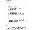
- FIG. 55A and 55B show the C code structure in Non-Patent Document 8 that cites the technique of Non-Patent Document 4.
- FIG. “Region3 ()” on the first line in FIG. 55A is a description of the execution operation of the machine language instruction in the specific address range. Each command will be described below.
- the “switch statement” on the third line in FIG. 55A branches to the case statement of the corresponding instruction address depending on the value of PC (program counter: ac_pc in the figure).
- Non-Patent Document 8 The C code optimization technique of Non-Patent Document 8 (see 5. Optimization Techniques of Non-Patent Document 8) is applied to the C code description by applying the following two optimization techniques. Note that these optimization methods have already been realized in the C code shown in Non-Patent Document 4.
- Optimization 1 optimization 1: In a normal instruction where the PC does not change discontinuously (branch, call, etc.), the next instruction becomes the immediately following case statement, so the useless break statement is deleted.
- Optimization 2 Updates the PC only when the PC changes discontinuously (branches, calls, etc.).
- Non-Patent Document 8 is said to be the fastest than the existing technology at that time, and yet it is reported that the simulation execution time is 14 to 54 times that of native execution.
- instruction set simulator source code problems relating to the C code of the instruction set simulator (hereinafter referred to as “instruction set simulator source code”) obtained by the methods of Non-Patent Documents 4, 8, and 9 will be described.
- Non-Patent Document 7 Page 3, right column, first paragraph:
- Each instruction of the decoded application corresponds to respective behavior function call in the generated simulator. These functions must be accessed randomly, as all of them can be a potential target of a jump instruction. ... The switch is based on the Program Counter.) Missing label information. Therefore, there is no information for determining which instruction can be a branch destination address. For this reason, based on the premise that “all” instructions can be branch destination addresses, a structure is required in which execution can transition directly from the switch statement to the instruction operation code of each case statement.
- simulation execution time is 14 to 54 times longer than native execution, so it is not practical to use the instruction set simulator source code for porting to another CPU because it involves a large overhead.
- the cause of the increase in simulation execution time comes from the switch statement related to the PC and the structure of the case statement corresponding to the address of each machine language instruction.
- a sixth problem is a lack of program control flow analysis.
- the instruction set simulation technology is focused on the part that implements the simulation function of the processor, and has a history of developing without sufficient cooperation with the compiler / decompiler technology. Therefore, there is no instruction set simulator that incorporates a program control flow analysis mechanism of compiler technology.
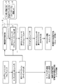
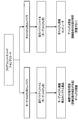
- FIG. 56 shows the programs of the conventional embedded system software development environment, and explain the merits and demerits of each case.
- FIG. 56 shows a software development environment for an embedded system that does not use a conventional instruction set simulator.
- software development environments for embedded systems that do not use an instruction set simulator include a target CPU embedded system product (actual machine) and a host CPU installed computer.
- the software development environment is a target CPU embedded system product (actual machine)
- the target CPU program source code or assembly code is converted into a machine language executable binary file by the target CPU compiler.
- the executable binary file is stored in the memory of the embedded system product with the target CPU.
- the software development environment is a computer with a host CPU
- the program source code or assembly code for the target CPU is converted into a machine language executable binary file by the host CPU compiler.
- the executable binary file is stored in a computer with a host CPU.
- the developed program source code or assembly code is incorporated into the host CPU-equipped computer and is not a real machine, so detailed operation cannot be reproduced.
- the host CPU-equipped computer since it is a computer with a host CPU, test cases for various conditions can be set, and debugging work for error correction is easy.
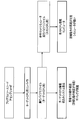
- FIG. 57 shows a software development environment for an embedded system using a conventional instruction set simulator.
- the program source code or assembly code for the target CPU is converted into a machine language executable binary file by the target CPU compiler.
- the execution binary file is converted into an execution binary file for the host CPU by an instruction set simulator.
- the execution binary file for the host CPU is executed on the computer with the host CPU. Since the execution binary file for the target CPU is converted to the execution binary file for the host CPU by the instruction set simulator, the detailed operation can be reproduced on the host CPU-equipped computer.
- the decompiler technology has the following problems. First, it is difficult to restore the data type. Second, it is difficult to analyze the program control flow of “indirect branching”. Third, it is difficult to restore function arguments and return values. Fourth, the source code output by the decompiler in terms of completeness has the following two problems. First, many existing decompilers cannot be made compilable without manual editing. As a second problem, programs that can be handled are limited due to the limitation of program complexity.
- Non-Patent Document 1 solves the problem that it is difficult to restore the first data type with a highly readable source output, and it is difficult to analyze the program control flow of the second “indirect branch”. Solves problems such as difficulty in restoring return values. However, the fourth integrity problem is unresolved.
- the instruction set simulator is satisfied with the fourth completeness that has not been solved by the decompiler technology.
- the instruction set simulator has a problem that it takes 14 to 54 times as much simulation time as the original program is directly executed by the host CPU (native execution).
- Non-patent documents 5 and 10 that output the machine language instructions of the target CPU directly as machine language instructions of the host CPU can realize a simulation time almost comparable to the native execution time.
- Non-Patent Documents 5 and 10 that output machine language instructions as other machine language instructions one platform cannot be ported to another platform, the program to be converted cannot be analyzed, virus detection, decoding, and analysis are not possible. There are problems such as being unable to do so.
- Non-Patent Documents 5 and 10 are problems that convert the decoding result of the machine language instruction into the C source code.
- the instruction set simulators of Non-Patent Documents 4, 8, and 9 have the following problems to be solved.
- the present invention was devised in view of the above circumstances, and can reliably restore a source program description file (instruction set simulator source code: C language description) from an execution binary and output a source program description file that can be easily analyzed.
- An object of the present invention is to provide an instruction set simulator that can construct a high-speed instruction set simulation environment and a simulator generation method thereof.
- An instruction set simulator is an instruction set simulator generated by converting a machine language program into a program source code, and includes a subroutine detection means for detecting a subroutine included in the machine language program, and the machine Branch instruction detecting means for detecting a branch instruction having a branch destination address among instruction words included in the word program, and subroutine calling for detecting a subroutine calling instruction having a subroutine call destination address among the instruction words included in the machine language program Instruction detection means, subroutine source code output means for outputting the program source code of each subroutine unit in which the machine language program is detected by the subroutine detection means, and an identifier indicating the branch destination address as the branch destination of the program source code Identifier adding means for adding to an instruction; unconditional branch instruction output means for outputting the branch instruction of the machine language program as an unconditional branch instruction to the instruction having the identifie
- the simulator generation method for the instruction set simulator of the ninth aspect of the present invention is a method for realizing the instruction set simulator of the first aspect of the present invention.
- the subroutine detecting means, the branch instruction detecting means, the subroutine calling instruction detecting means, and the identifier adding means are included, it is determined which instruction can be a branch destination address. It has information (solution of the first problem).
- a branch instruction of the machine language program is output as an unconditional branch instruction in the program source code, and a subroutine included in the machine language program is generated as a subroutine of the program source code.
- the hierarchical structure of the machine language program can be restored (solution of the fourth problem). Therefore, the compiler can be effectively optimized (solution of the third problem) and the processing speed is high (solution of the second problem). Also, the completeness of the instruction set simulator can be realized.
- the instruction set simulator is the simple branch instruction according to the first aspect, wherein the branch instruction detecting means detects a simple branch instruction that can specify a branch destination address among instruction words included in the machine language program. Instruction detecting means and data dependent branch instruction detecting means for detecting a data dependent branch instruction in which a branch destination address included in the machine language program is determined by a register value or a memory value.
- a simple branch instruction can be detected by the simple branch instruction detection means, and a data dependent branch instruction can be detected by the data dependent branch instruction detection means. It can be easily performed (solution of the first and sixth problems).
- an instruction set simulator for the second aspect of the present invention, the jump table recording means for recording a branch destination address of the data dependent branch instruction of the machine language program in a jump table information storage unit, and the jump Based on the branch destination address of the data-dependent branch instruction from the table information storage unit, the corresponding jump table information is retrieved, and the unconditional branch instruction of the program source code is retrieved using the retrieved jump table information.
- Data-dependent branch instruction generation means for generating.
- the simulator generation method for the instruction set simulator of the tenth aspect of the present invention is a method for realizing the instruction set simulator of the third aspect of the present invention.
- the unconditional branch instruction of the program source code can be generated smoothly and easily from the branch instruction of the machine language program using the jump table information (the first and sixth aspects). Solution of the problem).
- the subroutine call instruction detecting means detects a simple subroutine call instruction that can specify a call destination address among instruction words included in the machine language program.
- Simple subroutine call instruction detecting means and data dependent subroutine call instruction detecting means for detecting a data dependent subroutine call instruction in which a call destination address included in the machine language program is determined by a register value or a memory value.
- the simple subroutine call instruction can be detected by the simple subroutine call instruction detecting means
- the data dependent subroutine call instruction can be detected by the data dependent subroutine call instruction detecting means
- the subroutine call instruction in the program source code can be detected. It can be generated smoothly and easily (solution of the first and sixth problems).
- the instruction set simulator according to the fourth aspect, wherein the subroutine call instruction output means generates a subroutine machine language address table relating to information in which a subroutine name and a subroutine machine language address are paired.
- Address table generation means subroutine address search processing instruction generation means for generating a subroutine address search processing program for searching a subroutine on the program source code from a subroutine machine language address and obtaining a subroutine address on the program source code;
- the data dependence for performing the process of specifying the subroutine called the data dependent subroutine calling instruction of the program source code by the subroutine address search processing instruction and calling the subroutine And a subroutines call instruction generation unit.
- the eleventh instruction set simulator generating method of the present invention is a method for realizing the fifth instruction set simulator of the present invention.
- An instruction set simulator is the instruction set simulator according to any one of the first to fifth aspects, wherein the register value of the machine language program is described as a subroutine argument variable or a local variable on the program source code. Register variable expansion means.
- the simulator generation method for the instruction set simulator of the twelfth aspect of the present invention is a method for realizing the instruction set simulator of the sixth aspect of the present invention.
- the register variable expansion means describes the register value of the machine language program as a subroutine argument variable or a local variable on the program source code (the third and fourth variables). Therefore, the processing speed of the instruction set simulator can be increased (solution of the second problem).
- an instruction set simulator according to any one of the first to fifth aspects of the present invention, wherein the program source code is a C language program and relates to a switch statement relating to a program counter and each instruction address.
- An unconditional branch instruction and a subroutine call instruction to an instruction having an identifier on the program source code are used without using the code structure of the case statement, and the subroutine of the machine language program and the subroutine of the program source code are The subroutine hierarchy in the machine language program is restored to the subroutine hierarchy in the program source code.
- the program source code is a C language program, and does not use the code structure of the switch statement relating to the program counter and the case statement relating to each instruction address. Since an unconditional branch instruction to an instruction having an identifier and a subroutine call instruction are used, optimization can be performed effectively. Also, the subroutine of the machine language program and the subroutine of the program source code correspond to each other, and the subroutine hierarchy in the machine language program is restored to the subroutine hierarchy in the program source code (solution of the fourth problem). Can be effectively implemented (solution of the sixth problem), and the processing speed of the instruction set simulator is high (solution of the second problem). In addition, the program source code is highly readable and easy to analyze. Therefore, it is possible to easily analyze malware, viruses, etc. (solution of the fifth problem).
- the instruction set simulator of the eighth aspect of the present invention is the same as any one of the first to fifth aspects of the present invention, since the symbol information is missing in the machine language program.
- a machine language address that is not registered in the subroutine machine language address table is called by a data dependent subroutine instruction
- the instruction set is recorded after the unregistered machine language address is recorded.
- the thirteenth instruction set simulator generation method of the present invention is a method for realizing the eighth instruction set simulator of the present invention.
- an instruction set simulator capable of reliably restoring a source program description file from an execution binary, outputting a source program description file that can be easily analyzed, and constructing a high-speed instruction set simulation environment, and a method for generating the simulator. Can be provided.
- the figure which shows the sample of C source code The figure which shows the assembly instruction disassembled with the hexadecimal display of the address of each machine language instruction, and a 32-bit machine language instruction.
- the functional block diagram of a data dependence branch information extraction part The figure which shows the machine language instruction and assembly instruction of the ARMv5 instruction set of the jump_test function of FIG.
- the figure which shows 4 instructions of ARMv5 instruction set machine language and assembly description of the "jump_test" function of FIG. The figure which shows the macro call description with respect to the four ARMv5 instruction set machine language instructions of FIG.
- generation macro calls of FIG. The functional block diagram of a subroutine program source production
- the figure which shows the program description of a subroutine call instruction The figure which shows a conditional data dependence branch instruction and the unconditional branch instruction immediately after.
- the figure which shows the program description of a data dependence subroutine call instruction The figure which shows the output of the program description corresponding to the machine language instruction description of the "jump_test" function of FIG.
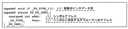
- the figure which shows the _FP_INFO_ structure which stores symbol address information.
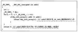
- the figure which shows the definition of _GET_FPI_ function which returns the pointer of _FP_INFO_ structure.
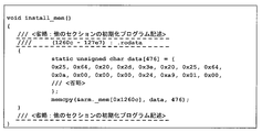
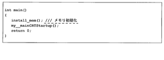
- the figure which shows the example of a memory initialization program description The figure which shows the example 1 of a program description of the highest function of an instruction set simulator.
- the figure which shows the program description which writes the argument information of the main function in CPU memory The figure which shows the functional block diagram of the machine language instruction analysis part of 2nd Embodiment.
- the figure which shows the input / output register of the ARMv5 machine language instruction of the "jump_test” function of FIG. The functional block diagram of a subroutine argument extraction part.
- the figure which shows the subroutine definition description output of a "jump_test” function The figure which shows the program description of a subroutine call instruction.
- the figure which shows the program description of a data dependence subroutine call instruction The figure which shows the software development environment for embedded systems using the instruction set simulator of 3rd Embodiment.
- the figure which shows the C code structure in the nonpatent literature 8 which quoted the method of the nonpatent literature 4.
- the figure which shows the software development environment for embedded systems which does not use the conventional instruction set simulator.
- the instruction set simulator of the present invention is an application of a program flow control analysis function and a data dependency analysis function, which have been constructed by a decompilation technique, to a Static compile method.
- the “completeness” of the instruction set simulator technology is secured, and the simulation speed can be improved to the same level as native execution.
- certain readability of the restored source code is ensured.
- “completeness” means that an executable binary can be “reliably” executed such that any program can be reliably simulated.
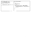
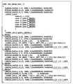
- Figure 1 shows a sample C source code.
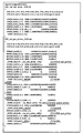
- Fig. 2 shows the C source code sample shown in Fig. 1 converted into machine language instructions in the ARMv5 instruction set of an embedded processor using C Compiler (gcc: GNU Compiler Collection).
- FIG. 2 shows the assembly instruction disassembled with the address of each machine language instruction and the hexadecimal representation of the 32-bit machine language instruction.
- the left four alphanumeric characters are the instruction address
- the middle eight alphanumeric characters are the hexadecimal machine language instructions
- the right is the assembly instruction.
- the features of the ARMv5 instruction set shown in Figure 2 are as follows: • 16 registers (r0, ..., r9, sl, fp, ip, sp, lr, pc): The program counter (pc) can be rewritten with normal instructions. Various program control can be realized by various instructions for updating pc.
- Execution condition All instructions include a 5-bit execution condition flag, and if the execution condition is not met, execution is skipped.
- popgt, beq suffix ble instruction (gt, eq, le) is execution condition (g reater t han, eq ual , l ess or e qual) is, execution conditions suffix no instruction is always executed (Al: al ways).
- a “constant pool” embedded in the program area is used as a mechanism for loading 32-bit immediate values (constants) into registers.
- the data (0x1b308, 0x1b404, 0x1b308) at each address of 0x8234, 0x8238, and 0x8428 corresponds to the constant pool.
- These constants are loaded by load instructions (0x8218, 0x8220, 0x83c4) with pc as the base address.
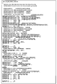
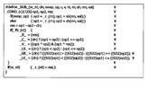
- FIG. 3 shows a C source description output by this embodiment. The characteristics of the C source description output by the instruction set simulator of this embodiment will be described below.
- one machine language instruction has one-to-one correspondence with one C macro call instruction (LDR, ADD, CMP, etc.). That is, there is basically a feature that sequential processing is performed in the order of description of machine language source code. The actual instruction behavior is defined inside each C macro description. (Non-Patent Document 4 also uses the same C macro description: see FIGS. 53 and 54)
- the second feature is that the function of the original C source code (FIG. 1) and the function of the C description generated from the execution binary by the instruction set simulator of this embodiment have a one-to-one correspondence. That is, the function hierarchy of the original C source code is restored as it is to the C source description output by the instruction set simulator S of the present embodiment.
- a function argument for example, r0
- a parameter name corresponding to the CPU register.
- Other CPU registers that do not appear in function arguments are declared as function local variables. 3, r0, r1,..., R9, sl, fp,..., Pc are CPU general-purpose register variables (local variables), and cv, cc, ..., cle are CPU status register variables (described later).
- the stack pointer (sp) is passed as a function argument.
- the function return value is passed through the register (r0 in the above example) specified by the function call rules (compiler dependent) (line 12 in FIG. 3). Even if the original C function is a void type (a function with no return value), a description that passes r0 is output, but there is no problem in program operation. This is because the compiler assumes that the value of r0 is rewritten before and after the function call, so there is no problem even if a return value of “empty” (undefined value) is assigned to r0.
- the third feature is that a C label (L_083f0, L_083fc, L08400, etc.) (identifier) (identifier) is placed before the branch destination instruction, and the branch instruction is described by a goto statement of an unconditional branch instruction.
- the program control flow of the executable binary can be expressed as it is in the C language description.
- ⁇ Instruction set simulator execution time The characteristics of the C source code structure according to the present embodiment (the present invention) can be confirmed by actually compiling and executing the C source code by the instruction set simulator of the present embodiment.
- the internal structure of the C macro that appears in the C source code in Fig. 3 is composed of fairly complex code in order to faithfully express complex CPU operations with C language descriptions.
- This section describes how the C source code output by this instruction set simulator generates efficient execution code (execution binary of the host CPU) despite the C description of complex CPU operations.
- the host CPU refers to a processor (such as a processor mounted on a desktop notebook PC) that executes a software tool such as an instruction set simulator.
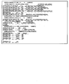
- FIGS. 4A and 4B show the C description output of the execution binary according to the present invention and the machine language instruction of the recompiled host PC (X86 instruction set) superimposed on each other.
- the part enclosed by the ruled lines in FIGS. 4A and 4B is the machine language instruction of the recompiled host PC (X86 instruction set).
- a prime number calculation program including the code shown in Fig. 2 of the test program Host CPU: Intel Xeon 3.4GHz (Quad core), 3.25GB memory
- native execution time was 0.7580 seconds.
- the simulation execution time of the prime number calculation program including the code of FIG. 2 of the test program by the instruction set simulator S of the present embodiment (the present invention) is 0.7699 seconds, and the ratio of the native execution time: 0.7580 seconds It was 1.016 times.
- FIG. 5 shows a software development environment for an embedded system using the instruction set simulator of the first embodiment.
- the target CPU refers to a processor (such as a processor installed in an embedded system) that executes an execution binary machine language instruction.
- the host CPU refers to a processor that executes a software tool such as an instruction set simulator. For example, it refers to a processor mounted on a desktop notebook PC.
- the program source code or assembly code for the target CPU is converted into an execution binary file for the target CPU by the target CPU compiler.
- the execution binary file is stored and executed in the memory of the embedded system product with the target CPU.
- the machine language instruction analysis unit 1 of the instruction set simulator S When simulating with the instruction set simulator S, the machine language instruction analysis unit 1 of the instruction set simulator S reads the execution binary file for the target CPU, executes the machine language instruction analysis process, and executes the symbol information list r1, branch destination address list Outputs r2 and jump table information list r3.
- the program source code output unit 2 of the instruction set simulator S reads the execution binary file for the target CPU, the symbol information list r1, the branch destination address list r2, and the jump table information list r3. Then, the program source code output unit 2 outputs an instruction set simulator program source code (program set code of the instruction set simulator S).
- the instruction set simulator program source code corresponds to the C language source code described above.
- the instruction set simulator program source code is converted into an execution binary file for the host CPU by the host CPU compiler.
- the execution binary file for the host CPU is loaded into the memory of the computer with the host CPU and executed.
- the instruction set simulator S is realized using software. Note that at least a part of the instruction set simulator S may be configured by hardware.
- program execution binary data machine language data
- OS compiler language data
- storage position refers to an offset value from the beginning of the ELF file
- position stored in the ELF file is designated by the number of bytes.
- ELF header Located at the beginning of the ELF file, it contains all the information necessary to obtain various data stored in the ELF.
- the main items are as follows.
- the file type is an executable file, a linkable file, a shared library, or the like.
- CPU model / version entry point (first address when executing a program), storage location of the program header table, ELF header size of the storage location of the section header table, size and number of entries of one entry in the program header table, section There are a size and the number of entries of one entry of the header, a section header table index storing a section name character string table, and the like.
- the program header table includes information necessary for the OS and the like to prepare for memory area reservation and memory initialization when the ELF file is executed by the CPU.
- An entry contains as a main item the following information about one segment (consisting of one or more sections):
- the segment type includes a readable segment and a dynamic link segment.
- there are a storage location of the segment a virtual address and a physical address at which the segment is arranged on the memory, a file size and a memory size of the segment, a segment access right (combination of executable, readable, and writable).
- the binary data part stores machine language instruction data (program memory data) and initial value data of the data memory.
- Section header table A section exists as a constituent unit of a memory area (program memory / data memory) and as a storage unit of supplementary information.
- One entry in the section header table contains the following information about one section as the main items.
- As the section name string information there is an index to the section name string table section in the section header.
- the section type includes program definition information (memory area constituent unit, debug information, etc.), symbol table (program address information, variable address information), character string table, relocation information, dynamic link information, and the like.
- the section attributes include memory area occupation (readable), writable, executable, and the like.
- Symbol table A symbol mainly includes program address information and variable information stored in a memory, and belongs to any section.
- the symbol table is stored as one entry in the section header table.
- the symbol contains the following information as main items.
- symbol name character string information there is an index to the “symbol name character string table” in the section header.
- symbol name character string table There is the memory address of the symbol and the size of the symbol.
- type attribute an attribute of a symbol associated with a function or another executable instruction is referred to as “FUNC type”.
- section index there is an index of a section to which the symbol belongs.
- ELF header item Address where the first instruction to be executed after program startup is stored
- the address area of the segment with “executable” access right is defined in the program header table.
- the address area of the section with the “executable” attribute is defined in the section header table.
- the memory address of the symbol included in the address area of the section having the “executable” attribute is defined in the symbol table defined in the section header table.
- the information that is guaranteed to be defined in the executable file is the address area of the entry point and executable segment, and the section header table can be omitted, so section information and symbol information may be missing. possible.
- symbol information list has a “symbol information” list structure. “Symbol information” stores information items of symbol addresses and instruction address lists regarding executable symbols. (A) Symbol address (B) Instruction address list: It has a list structure of addresses of all instructions reachable from the symbol address.
- Instruction address temporary list Instruction addresses that store the machine language instructions to be processed and are updated as the processing of the machine language instruction analyzer 1 proceeds (the instruction addresses to be processed are read and deleted) It has a list structure of
- Branch Destination Address List has a list structure of branch destination addresses of conditional branch instructions and unconditional branch instructions.
- next instruction information temporary list has a list structure of “next instruction information”. “Next instruction information” is information regarding an instruction (hereinafter referred to as “next instruction”) that can be executed after a certain instruction is executed, and includes the following data items.
- next instruction address B) The next instruction type is one of the following three types.
- “Jump table information list r3” a list structure of “jump table information”.
- the “jump table information” is information generated by “processing of the data dependent branch information extraction unit 2” described later, and includes the following data items.
- C) Branch destination address table (one entry stores a branch destination address. “Number of entries” “jump table size”)
- FIG. 7 shows a functional block diagram of the machine language instruction analysis unit of the first embodiment.
- the machine language instruction analysis unit 1 of the first embodiment has a role of analyzing a machine language in order to convert a machine language to be analyzed executed by the target CPU into a C code.
- the machine language instruction analysis unit 1 includes a symbol address preprocessing unit 1a, a symbol address acquisition unit 1b, an instruction address acquisition unit 1c, a next instruction information extraction unit 1d, an address list update unit 1e, and a data dependent branch extraction unit 2. ing.
- the machine language instruction analysis unit 1 outputs a symbol information list r1, a branch destination address list r2, and a jump table information list r3 in order to create a C code from the machine language to be analyzed.
- a process of the machine language instruction analysis unit 1 of the first embodiment a process flow when a premise that a section header table exists and a symbol table is defined therein will be described.
- the symbol address preprocessing unit 1a creates a “symbol address temporary list”.
- the symbol address preprocessing unit 1a is a symbol included in an address area of a section having an executable attribute in a symbol table defined in the section header table, and is associated with a function or another executable instruction. Symbols with attributes (see “FUNC type symbol type attributes” above) are considered “executable symbols”.
- the symbol address preprocessing unit 1a creates a “symbol address temporary list” by “adding” all addresses of “executable symbols” to the “symbol address temporary list”. Thereafter, the process proceeds to the symbol address acquisition unit 1b.
- the “symbol information” regarding the current symbol does not exist in the “symbol information list”
- the “symbol information” of the extracted current symbol is generated as follows. This symbol information is hereinafter referred to as “current symbol information”. 1) Set the “current symbol” address in “symbol address” of “symbol information”. 2) Generate “symbol name string”. When the symbol is registered in the “symbol table”, the “symbol name character string information” in the “symbol table” is acquired and generated.
- next instruction information extraction unit 1d reads binary data stored in the “binary data part” of the “execution binary file” based on the “current instruction address”, and regards this binary data as a machine language instruction. Then, the next instruction information extraction unit 1d decodes (interprets) the machine language instruction, executes the following processes (1) to (4) corresponding to the instruction type, and generates “next instruction information”. “Add” to the “next command information temporary list”.
- next instruction information extraction unit 1d In the case of a “simple branch instruction” (a branch instruction whose branch destination address can be specified only by an instruction word), the next instruction information extraction unit 1d generates “branch type” next instruction information from the branch destination address.
- a “data dependent branch instruction” a branch instruction whose branch destination address is determined by a register value / memory value
- the branch destination cannot be specified directly by the instruction word alone, so the following processing is executed.
- “data dependent branch information extraction unit 2” described later is executed to extract “jump table information” from the jump table information list r3.
- the next instruction information extraction unit 1d generates “branch type” next instruction information for all branch destination addresses stored in the “branch destination address list r2” of the extracted “jump table information”.
- next instruction information extraction unit 1d In the case of a “simple subroutine call instruction” (subroutine call instruction whose call destination address can be specified only by an instruction word), the next instruction information extraction unit 1d generates “call type” next instruction information from the call destination address. (4) In the case of “data dependent subroutine call instruction” (subroutine call instruction whose call destination address is determined by the register value / memory value), the next instruction information extraction unit 1d selects “data dependent subroutine instruction” of “current symbol information”. “Flag” is set to “1”. The call destination address of the “data dependent subroutine call instruction” is resolved by another means described later.
- Instructions that may execute “immediate instruction” are all instructions except for the following cases.
- ⁇ Address list update unit 1e> Various address lists are updated from the “next instruction information temporary list” generated by the next instruction information extraction unit 1d as follows. (1) Updating by “next type” next instruction information “takes out” all “next type” next instruction information from “next instruction information temporary list” and adds them to the instruction address temporary list. (2) “Branch type” next instruction information is updated by “fetching” all the “branch type” next instruction information from the “next instruction information temporary list”, into the branch destination address list r2 and the instruction address temporary list. "to add.
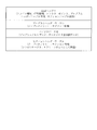
- FIG. 8 shows a sample C program of the function jump_test including the switch statement.
- the switch statement switch (n) [case 3:... case 8:... default:...]
- the jump_test function is implemented as a data-dependent branch instruction regarding the value of the variable n.
- the data dependent branch instruction operates by preparing the following instruction elements and data elements in advance.
- Jump table An address table that stores the head instruction address corresponding to each case statement in the switch statement.
- the first instruction address corresponding to case min_case_value: is stored in the first entry of the jump table.
- the last entry stores the first instruction address corresponding to case max_case_value :.
- the head instruction address corresponding to the default statement is stored if the default statement exists, and the default statement does not exist The head instruction address immediately after the switch statement is stored.
- Conditional branch instruction based on jump table offset value range determination A conditional branch instruction that branches when the range determination result is “false”.
- the branch destination address at this time is the first instruction address corresponding to the default statement when the default statement exists, and the first instruction address immediately after the switch statement when the default statement does not exist.
- Jump table storage memory read instruction and data-dependent branch instruction When the jump table offset value range judgment result is “true”, the memory address jt_addr where the jump table is stored is (jt_addr + jt_offset * a_size The data-dependent branch destination address stored in the memory address calculated in step) is read.
- a_size is the word length (byte length of the word size) of the address value, and is 4 (bytes) for a 32-bit instruction set and 8 (bytes) for a 64-bit instruction set.
- PC program counter
- the jump table storage memory read instruction and the data dependent branch instruction may be implemented as a single machine language instruction (ARMv5 instruction set, x86 instruction set, etc.).
- Jump table offset value range determination instruction (2) Conditional branch instruction by jump table offset value range determination (3)
- Jump table storage memory read instruction (4)
- Data dependent branch instruction (3), (4 ) May be one machine language instruction (described above). (2) may come immediately after (4).
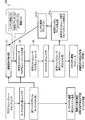
- FIG. 9 shows a functional block diagram of the data dependent branch information extraction unit.
- the data dependent branch information extraction unit 2 performs the following series of processes. Assume that the address of the data dependent branch instruction has already been given by the next instruction information extraction unit 1d (FIG. 7).
- (1) “Jump table storage memory read command” extractor 2a When the data dependent branch instruction itself performs a memory read, this instruction is a “jump table storage memory read instruction”. In the case of a data-dependent branch instruction that assigns a register value to a PC, an instruction that loads a memory into a register before the data-dependent branch instruction is executed is a “jump table storage memory read instruction”.
- Jump table storage memory address analysis unit 2b and jump table offset register extraction unit 2c In the jump table storage memory read instruction, when the memory address is calculated in the format of “base address value (fixed address) + offset value”, the “base address value” is specified as “jump table storage memory address value”, The register for storing the offset value is specified as “jump table offset register”.
- base address value is given as an “absolute address” (information of the address value itself is specified by a machine language instruction) and a “PC relative address” (an offset value added to the current instruction address is a machine language). May be calculated as specified by the instruction).
- Branch destination address information reading part 2f All the branch destination addresses stored in the jump table are read from the information of the “jump table storage memory address value” and “jump table size” specified above, and stored in the branch destination address table (machine language address table).
- Jump table information generator 2g Generates “data dependent branch jump table information” consisting of “data dependent branch instruction” given in advance and “jump table size” and “branch destination address table” obtained in steps (1) to (4) above. And “add” to the “data dependent branch information list”. The information of the generated data dependent branch jump table is used in the next instruction information extraction unit 1d.
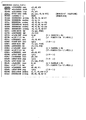
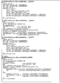
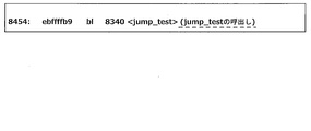
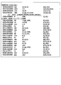
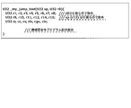
- FIG. 10 shows machine language instructions and assembly instructions of the ARMv5 instruction set of the jump_test function of FIG. Each line is written in the order of "instruction address" (hexadecimal notation), "machine language instruction data” (hexadecimal notation), and "assembly instruction description". For instructions that affect the PC (program counter), The instruction type is also shown. In the following description, the subsequent machine language instruction analysis processing will be described on the assumption that the address “0x8340” of “jump_test” is acquired from the “symbol address temporary list”.
- Table 1 shows the machine language instruction analysis processing from 0x8340 to 0x834c.
- next instruction information is sequentially extracted based on the instruction of the symbol address 0x8340. Since each instruction of 0x8340, 0x8344, and 0x8348 is a “normal instruction” that does not affect the PC, only the “immediate instruction” is the next instruction. These next instruction addresses are “added” to the “instruction address temporary list” by the address list update unit 1e, and then immediately fetched by the instruction address acquisition unit 1c. B) Since the instruction of 0x834c is a “data-dependent branch instruction”, the next instruction information extraction process of this part is performed in the data-dependent branch information extraction unit 2.
- Table 2 shows the processing of the data dependent branch information extraction unit 2 at 0x834c.
- the data dependent branch information extraction unit 2 firstly specifies that the “jump table storage memory read instruction” at 0x834c is the same as the data dependent branch instruction, from which the jump table storage memory address is 0x8354, and the jump table size is 6 is identified. Finally, six branch destination addresses [0x8384, 0x839c, 0x836c, 0x83a4, 0x836c, 0x8384] are read from address 0x8354 to generate “jump table information”.
- Table 3 shows the process of the 0x834c next instruction information extraction unit 1d and the process of the 0x8350 machine language instruction analysis unit 1.
- next instruction information temporary list is also generated as the next instruction for the immediately following instruction (0x8350).
- the six branch destination addresses include duplicate addresses, duplicate next instruction information is not added to the next instruction information temporary list.
- the address list update unit 1e four (non-overlapping) branch destination addresses are “added” to the “branch destination address list”, and five next instruction addresses (branch type / immediate type) are added to the “instruction address temporary list”. Added. "
- the instruction address acquisition unit 1c “takes out” the last address 0x8350 of the instruction address temporary list. Since this instruction is an “unconditional branch instruction”, the next instruction information extraction unit 1d extracts the branch destination address 0x839c as the next instruction address. Then, the address list updating unit 1e adds the branch destination address 0x839c to the “branch destination address list” and the “instruction address temporary list”. Here, since 0x839c exists in any list, these lists are not updated.
- Table 4 shows the machine language instruction analysis processing from 0x83a4 to 0x83b4.
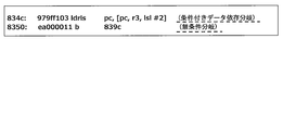
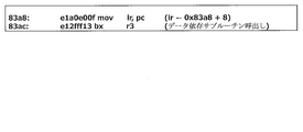
- Table 5 shows 0x83ac, 0x83a8 machine language instructions and C language instructions.
- 0x83ac is a “data-dependent branch instruction” that jumps to the value of register r3, but an instruction that assigns pc (actual value is the current instruction address 0x83a8 + 8) to link register lr immediately before 0x83a8 Therefore, it can be determined that the instruction of 0x83ac is actually a “data dependent subroutine call instruction”.
- variable f is a function pointer (variable)
- f (n) is a subroutine call via the function pointer is there.
- jump table information in “data dependent branch instruction” is fixed data in memory and can be extracted
- call destination address in “data dependent subroutine call instruction” is program execution In general, it is difficult to extract a callee address.
- next instruction information of the data dependent subroutine call instruction is only “immediate instruction”, and the resolution of the data dependent subroutine call destination address is handled by another means described later. That is, the next instruction information extraction process of the “data dependent subroutine call instruction” is handled in the same manner as the “normal instruction”.
- Table 6 shows the machine language instruction analysis processing of other parts.
- the end address 0x8384 of the temporary instruction address list is taken and the next instruction (immediate instruction) address is continuously analyzed from the instruction at address 0x8384.
- a return instruction of 0x8398 (no next instruction) is reached.
- the instruction address acquisition unit 1c detects that the "instruction address temporary list” is “empty” (all instruction analysis within the symbol has been analyzed), and the “instruction address list” in the "current symbol information” "Is sorted in ascending order.
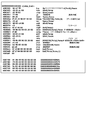
- FIG. 11 shows machine language instructions and assembly instructions of the x86 (64-bit) instruction set of the jump_test function. From the left, each line is "instruction address" (6-digit hexadecimal notation), “machine language instruction data” (separated by 2 hexadecimal digits in order from left to right), “assembly instruction description” It is written in order. In addition, about the instruction
- Table 7 shows the processing of the machine language instruction analysis processing unit 1 up to 0x400560-0x40056e of the jump_test function of FIG.
- next instruction information is extracted sequentially based on the instruction at symbol address 0x400560, and each instruction at 0x400560, 0x400563, 0x400567 is a "normal instruction” that does not affect the PC, so "immediate instruction” Only becomes the next instruction.
- the instruction at 0x40056a is a “conditional branch instruction”
- the branch destination address 0x400575 and the immediately following instruction address 0x40056c are the next instruction addresses.
- the instruction at 0x40056e is a “data dependent branch instruction”
- the processing of the next instruction information extracting unit 1d in this part is performed by the data dependent branch information extracting unit 2.
- Table 8 shows the data-dependent branch information extraction process at 0x40056e in FIG.
- the “jump table storage memory read instruction” is the same as the data-dependent branch instruction, from which it is specified that the jump table storage memory address is 0x400738 and the jump table size is 6. .
- six branch destination addresses [0x400591, 0x400575, 0x400580, 0x40059a, 0x400580, 0x400591] are read from the address 0x400738, and “jump table information” is generated.
- Table 9 shows the next instruction information extraction process of 0x40056e.
- Six branch destination addresses are acquired from the jump table information generated by the data dependent branch information extraction unit 2 for the instruction of 0x40056e, and a next instruction information temporary list is generated.
- the six branch destination addresses include duplicate addresses, duplicate next instruction information is not added to the next instruction information temporary list.
- the address update unit four (non-overlapping) branch destination addresses are “added” to the “branch destination address list r2” and “instruction address temporary list”, but the next instruction address 0x400575 exists in both lists. Actually, three addresses are added.
- Table 10 shows the process of the machine language instruction analysis unit 1 in other parts. Immediately before 0x40059a, the instruction address list and the instruction address temporary list are as shown in the upper column of Table 10.
- Instruction address to be analyzed in column D of Table 10 (0x400575, 0x400577, 0x40057b): The last address 0x400575 of the instruction address temporary list is taken, the next instruction address (immediate type) is continuously analyzed, and the return instruction (0x40057b) No next command is reached.
- the “Instruction Address Acquisition Unit 1c” detects that the “Instruction Address Temporary List” is “Empty” (all instructions in the symbol are analyzed), and the “Instruction Address List” in “Current Symbol Information” "Is sorted in ascending order.
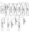
- FIG. 12 shows the configuration of the instruction set simulator together with the execution binary file to be analyzed and the instruction set simulator program source code output from the instruction set simulator.
- the instruction set simulator S includes a machine language instruction analysis unit 1 and an instruction set simulator program source code output unit 3.
- the instruction set simulator program source code output unit 3 outputs the instruction set simulator program source code from the symbol information list r1, the branch destination address list r2, and the jump table information list r3 having the information extracted by the machine language instruction analysis unit 2. To generate.
- the instruction set simulator program source code output unit 3 includes a subroutine program source generation unit 3a, a symbol address information table source generation unit 3b, a memory initialization program description generation unit 3c, and a main function program description generation unit 3d. ing.
- the instruction set simulator program source code 4 includes a subroutine program source 4a, a symbol address information table source 4b, a main function source 4c, a memory initialization processing source 4d, and a machine language instruction program generation macro definition source 4e prepared in advance. Have.
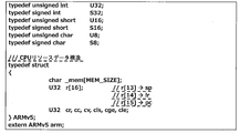
- CPU resource refers to memory and CPU registers (general-purpose registers, internal status registers, etc.), and the state of these “CPU resources” is true to the CPU operation as actual hardware on the instruction set simulator program. Must be reproduced on the simulator program.
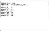
- FIG. 13 shows an example of the data structure description of the CPU resource in the ARMv5 instruction set simulator program
- FIG. 14 shows the CPU resource reference macro definition and the instruction execution condition determination macro definition.
- Memory Declared as an array of char type (8 bits).
- MEM_SIZE memory size specifies a necessary memory size (reserving a necessary stack area) from information obtained from a “program header table” included in the execution binary file.
- Status register Declared as six 32-bit variables (unsigned) consisting of cr, cc, cv, cls, cge, and cle. These are used as information indicating the state of the CPU for determining the “instruction execution condition” in the ARMv5 instruction.
- a mechanism that usually determines 14 execution conditions based on a combination of four internal register bits (Z: zero, N: negative, V: overflow, C: carry) Is implemented. It is also possible to realize the same 4-bit status register as a resource description, but here, by declaring it as six 32-bit variables, it is possible to determine the "instruction execution condition" on the software. It is intended to reduce the amount of calculation (described later).
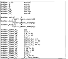
- Instruction execution condition determination by the above six status register variable reference macros is performed on the program description. There are 15 types of instruction execution conditions as follows. (The following is a comparison between the condition determination condition of the normal Z / N / V / C 4-bit status register and the condition determination expression based on the six status register variable reference macros in FIG. 14)
- the “machine language instruction program generation macro” is a programming description technique having a function of partially generating an execution program description based on several arguments (variables, constants, character strings).
- machine language instruction program macro is defined for each type of machine language instruction used (the macro definition is, of course, a description specific to the instruction set of the target CPU).
- the machine language instruction program generation macro definition source 4e is prepared in advance because it is information that does not depend on the “execution binary file” to be analyzed.
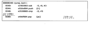
- FIG. 16 shows a “machine language instruction program macro” call description corresponding to the four machine language instructions shown in FIG. Hereinafter, each machine language instruction program macro will be described.
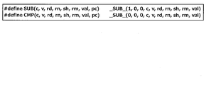
- FIG. 17 shows the SUB macro definition and the CMP macro definition.
- the SUB macro is called in response to the sub instruction, and the CMP macro is called in response to the cmp instruction.
- (2) _SUB_ macro shown in FIG. 18 Internal macro further called by the SUB macro and the CMP macro.
- the meanings of the arguments used in the SUB macro and CMP macro are as follows.
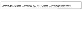
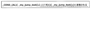
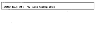
- _COND_ macro An internal macro further called by the _SUB_ macro, which is defined in FIG. “_COND_ (c)” is macro-defined as “if _COND _ ## c ## _”. Since “##” is a “character string concatenation preprocessor”, for example, _COND_ (AL) is converted to “if _COND_AL_”, and “_COND_AL_” is further converted to “(1)” by the macro definition.
- FIG. 19 shows another macro called inside the _SUB_ macro.
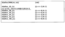
- IMM (rm, val) In the SUB macro call and the CMP macro call in FIG. 16, “IMM” is given as the macro argument sh.
- sh The description of “sh (rm, val)” in FIG. 18 is converted into “IMM (rm, val)”, and finally converted into “(val)” in this IMM macro definition.
- -_FS_ (v) converted to ((v >> 2) & 1).
- this is equivalent to an operation for extracting the lower 2 bits of v (counting from the 0th bit).
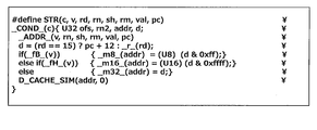
- FIG. 20 shows the STR macro definition called in FIG. 16, and FIG. 21 shows the _ADDR_, _D_CACHE_SIM macro definition called inside the macro.
- FIG. 21 shows the _ADDR_, _D_CACHE_SIM macro definition called inside the macro.
- push [lr] in the assembly instruction description in the original machine language, this means that the stack pointer sp (arm.r [13]) is decremented (1 data (This is implemented as a str instruction in ARMv5, which writes the link register lr (arm.r [14]) to the memory using the value obtained by subtracting the address of the word) as the memory address.
- _ADDR_ macro This is called inside the STR macro and generates the following program that calculates the memory write address. Macros _fU_ (v), _fP_ (v), and _fW_ (v) called from _ADDR_ are instruction attributes that specify an address offset calculation method, whether or not the base address register _r_ (rn) is updated, and the like.
- D_CACHE_SIM macro provides a mechanism to call the data cache simulation function D_Cache_Sim (defined separately) (see Figure 21) when cache simulation is enabled (when ENABLE_CACHE_MODEL is defined separately). . If the cache simulation is not valid, the description of D_CACHE_SIM (addr, isRead) (see FIG. 21) is converted to “empty character string”.
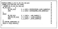
- FIG. 22 shows the LDR macro definition called in FIG. (Supplement: Although it is “pop [pc]” in the assembly instruction description of the original machine language, this is recorded in the above push [lr] with the stack pointer sp (arm.r [13]) as the memory address. The read “return instruction address value” is read from the memory, and the stack pointer is "incremented” (adds an address for one data word), and is implemented as an ldr instruction in ARMv5.)
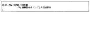
- Subroutine naming rules in program description The “subroutine naming rules” in the program description of the subroutine program source 4a shown in FIG. 12 will be described.
- the points to be noted in the subroutine naming rules are that, for example, in the C language, a subroutine name having a special meaning is reserved, such as the main function and the exit function, so it is necessary not to duplicate the reserved subroutine name. .
- a predetermined “prefix character string” (for example, “_my_”, etc.) is concatenated to the head of the “symbol name character string” included in the “symbol information” to be a “subroutine name character string”.
- the “subroutine name character string” corresponding to the symbol name “jump_test” is “_my_jump_test” when the “prefix character string” is “_my_”.
- the symbol name generation rule is generated as described above.
- the same “prefix character string” may be used.
- the subroutine name character string may be “_my_func_1234”.
- Subroutine program source generation unit 3a (FIG. 24) that generates a subroutine program source including a machine language instruction program generation macro call description as shown in FIG. 16 will be described.
- ⁇ Subroutine information acquisition unit 3a1> One symbol information is extracted from the symbol information list r1 generated by the machine language instruction analysis unit 1.
- the symbol information extracted here is referred to as “current symbol information”.
- ⁇ Subroutine definition description generator 3a2> Based on the “subroutine name character string” included in the “current symbol information”, a “subroutine definition description” as shown in FIG. 25 is generated. In the “first embodiment”, a description of a subroutine definition that has no return value (void type) and takes no arguments is generated.
- the instruction address acquisition unit 3a3 sequentially reads out “instruction addresses” from the head of the “instruction address list” of “current symbol information”.
- the read “instruction address” is hereinafter referred to as “current instruction address”.
- the “branch destination address list” obtained by the machine language instruction analysis processing of the jump_test function of the ARMv5 instruction set is [0x8384, 0x839c, 0x836c, 0x83a4] (see Table 3).
- the C language label descriptions corresponding to these branch destination addresses may be generated as, for example, “L_08384:”, “L_0839c:”, “L_0836c:”, “L_083a4:”.
- the machine language instruction type determination unit 3a5 reads binary data stored in the “binary data part” of the “execution binary file” based on the “current instruction address”.
- the binary data is regarded as a machine language instruction, and the machine language instruction is decoded (interpreted) (the same procedure as the machine language instruction decoding process of the next instruction information extraction unit 1d) to determine the following instruction types.
- -Instruction type Specifies a machine language instruction program generation macro name. This is information for generating macro names such as SUB, STR, CMP, LDR in FIG.
- Action register number Specify the operand register number and operation result storage register number.
- the following corresponds to the action register number: SUB (AL, 0x020, 3, 0, IMM, -1, 7) (action register number: 3, 0 STR (AL, 0x009,14,13, IMM, -1, ...) (Operation register number: 14, 13 CMP (AL, 0x024, 0, 3, IMM, -1, %) (Action register number: 0, 3 LDR (AL, 0x012,15,13, IMM, -1, %) (Action register number: 15, 13
- the argument “ ⁇ 1” also corresponds to the “rm” (second operand register ID: register number storing the second operand) argument of each macro (SUB / CMP: second operand register ID, STR / LDR: Offset register ID) corresponds to the fact that there is no corresponding register because the second operand or the offset operand is a constant.
- STR (AL, 0x009,14,13, IMM, -1,0x00000004, 0x08344)
- AL Execution condition (always: Unconditionally executed)
- 0x009 Corresponds to instruction bit field argument v (including address offset calculation method, presence / absence of address register update, data width information, etc.)
- IMM Supports shift attribute argument sh (address offset is immediate)
- 0x00000004 immediate data
- LDR (AL, 0x012,15,13, IMM, -1,0x00000004, 0x08380)
- AL Execution condition (always: Unconditionally executed)
- 0x012 Corresponds to instruction bit field argument
- v IMM Corresponds to shift attribute argument sh (address offset is immediate)
- 0x00000004 Immediate data
- a “machine language instruction program generation macro call description” is generated.
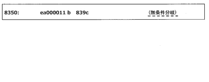
- the branch destination address is 0x839c and the label statement L_0839c: is inserted before the instruction program description (25th line in FIG. 10) of 0x839c by the program label description generation unit 3a4, the branch is made to this label.
- the program description of FIG. 27 is generated. Even in the case of conditional branching, it can be realized simply by inserting the character string (EQ, NE, etc.) of the corresponding execution condition instead of AL (always: execute unconditionally).
- the “subroutine name character string” of the call destination is searched for the corresponding symbol information from the “symbol information list” based on the call destination address, and the above described “symbol name character string” contained in the symbol information is described above.
- the “subroutine naming rule” is applied to generate the “subroutine name character string”, the program description of FIG. 29 that calls it is generated. Even in the case of a conditional execution subroutine call instruction, it can be realized simply by inserting a character string (EQ, NE, etc.) of the corresponding execution condition instead of AL (always: execute unconditionally).
- Jump table size 6 -Branch destination address table: [0x8384, 0x839c, 0x836c, 0x83a4, 0x836c, 0x8384]
- the execution condition (ls: less or same condition) of this “data dependent branch instruction”
- a program description as shown in FIG. 31 is generated.
- the label of the goto statement that appears after each case statement corresponds to the label of each branch destination address in the “branch destination address table” of the “jump table information”.
- the conditional branch corresponding to case 0: and case 5: corresponds to the default label.
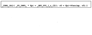
- a data dependent subroutine call instruction in which the call destination address is determined by the register value / memory value
- a data dependent subroutine is used by using “symbol address information” generated by the symbol address information table source generation unit 3b described later. The call is realized on the program description.
- 0x83ac is a “data-dependent branch instruction” that jumps to the value of register r3.
- pc actual value is the current instruction address 0x83a8 + 8
- link register lr immediately before 0x83a8. Since there is an instruction to be assigned to, it can be determined that the instruction at 0x83ac is actually a “data dependent subroutine call instruction”.
- the program description corresponding to the two instructions 0x83a8 and 0x83ac is as shown in FIG.
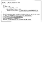
- FIG. 34 shows an output example of the subroutine program description corresponding to the machine language instruction description of the ARMv5 instruction set of the “jump_test” function in FIG.
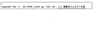
- _FP_INFO_ in FIG. 33 is a data structure storing symbol address information defined in advance as shown in FIG.
- _GET_FPI _ (_ r_ (3)) in FIG. 33 is the data of the corresponding “symbol address information” from the “symbol address information table” described later, based on the “symbol address” indicated by the value of _r_ (3). This is a function call that returns a pointer to a structure (described later).
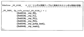
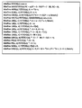
- FIG. 36 shows a program description for enabling the information in the “symbol information list” to be referred to on the program as the initial value setting of the array variable of the aforementioned _FP_INFO_ structure.
- 0x8218 is the initial value of the member variable addr of the _FP_INFO_ structure shown in FIG. 35
- _my_f0 is the initial value of the member variable func.
- _my_f0 is a subroutine name character string having the “prefix character string” “_my_” in the symbol name “f0”, and actually indicates the address value of the target subroutine. In this way, the initial value of the data structure for associating the “symbol address” in the executable binary file with the “subroutine address” in the program description can be set.
- the _GET_FPI_ function shown in FIG. 33 (a function that searches the corresponding _FP_INFO_ structure based on the “symbol address” and returns its pointer) is a simple program as shown in FIG. Can be realized. Also, if the number of symbols included in the symbol address information table is very large, there is a concern that the processing time of the _GET_FPI_ function will be long. In this case, the “binary tree search method”, “hash search method”, etc. And a high-speed search process based on the symbol address may be applied.
- the memory initialization program description generation unit 3c (instruction set simulator program source code output unit 3) generates a program description for initializing the memory area of the CPU in the program description of the instruction set simulator S.
- the initialization target of the memory area may include initial value data in the program area in addition to the data area in which the initial value is defined. Therefore, the program area is also subject to initialization.
- Memory initialization data exists in the binary data part of the execution binary file 5, and information on the positional relationship between each memory area and the “binary data part” is stored in the “segment” included in the “program header table”. They are defined in units or in units of “sections” included in the “section header table”.
- FIG. 38 shows an example of “memory initialization program description”.
- section unit memory initialization processing is described.
- the “.rodata” section with initialization data is defined in the address area of 0x1260c260- 0x127e7, and the specific initialization data is defined as the initialization data of unsignedsignchar data [476]. It is a program description that copies this array data to the address of & arm._mem [0x1260c] by memcpy function.
- FIG. 39 shows a program description example 1 of the highest function of the instruction set simulator.
- FIG. 40 shows a program description example 2 of the top-level function of the instruction set simulator.
- FIG. 41 shows a program description for writing the argument information of the main function to the CPU memory.
- the instruction set simulator program description structure generated as described above has the following characteristics.
- the subroutine in the “execution binary file” directly corresponds to the subroutine on the “program description”, and the “function hierarchy” of the “execution binary file” is the instruction set simulator S. Is directly reflected in the program description output.
- goto statements and label statements clearly correspond to simple branch instructions
- switch statements and case statements correspond to data-dependent branch instructions, making it easy to understand the flow of program control. Therefore, the readability of the program description is high, and code modification work such as program debugging work and program function expansion can be performed efficiently.
- a high-speed instruction set simulation environment By outputting a source program description file (instruction set simulator source code: C language description) having an equivalent function to the execution binary, and compiling and executing it, a high-speed instruction set simulation environment can be constructed as described above.
- a high-speed instruction set simulator having a simulation execution time almost equivalent to the native execution time for example, the time for compiling the program source for the target CPU into machine language and executing it in the CPU
- Equivalent function C description can be output from the execution binary for one target CPU, and the program can be ported to another CPU.
- Malware analysis is possible. Since analysis of the program source is easy, it is possible to easily analyze malware such as viruses, and to contribute to early development of virus removal software and firewalls.
- An instruction set simulator S with a simple tool framework structure that can realize high speed and completeness can be obtained.
- Non-Patent Documents 4, 8, and 9 used for actual use have the following problems to be solved.
- As a first problem there is no information for determining which instruction can be a branch destination address.
- simulation execution time is 14 to 54 times longer than native execution.
- code optimization in the compiler is very difficult.
- As a fourth problem a hierarchical structure is lacking.
- As a fifth problem a program control flow analysis mechanism is lacking as a sixth problem that the readability is extremely low as a source program.
- the branch destination address is added as a label (identification information) to the branch destination instruction, or there is a jump table or the like.
- the instruction set simulator 2S (see FIG. 43) of the second embodiment is obtained by adding a “subroutine argument extraction function” to the instruction set simulator S of the first embodiment. Since the other configuration is the same as that of the instruction set simulator S of the first embodiment, the same components are denoted by the same reference numerals and detailed description thereof is omitted.
- the instruction set simulator 2S of the second embodiment adds a “subroutine argument extraction function” to the instruction set simulator S of the first embodiment, and replaces the CPU registers with local variables and argument variables in the subroutine, thereby This is to further speed up the set simulation.
- FIG. 42 shows a functional block diagram of the machine language instruction analysis unit of the second embodiment.
- Machine language instruction analysis unit 21 of the second embodiment symbol address preprocessing unit 1a of the first embodiment, symbol address acquisition unit 1b, instruction address acquisition unit 1c, next instruction information extraction unit 1d, address list update unit 1e,
- a subroutine argument extraction unit 1f is newly added to the data dependence branch extraction unit 2.
- FIG. 43 shows the configuration of the instruction set simulator 2S of the second embodiment together with the execution binary file 5 to be analyzed and the instruction set simulator program source code 4 output from the instruction set simulator 2S.
- the instruction set simulator 2S of the second embodiment includes a machine language instruction analysis unit 21 and an instruction set simulator program source code output unit 23.
- the instruction set simulator 2S receives the execution binary file 5 and outputs a high-level instruction set simulator program source code 4.
- the instruction set simulator program source code output unit 23 shares subroutine arguments with the subroutine program source generation unit 3a, symbol address information table source generation unit 3b, memory initialization program description generation unit 3c, and main function program description generation unit 3d.
- the processing unit 3e is newly added.
- symbol address information table source generation unit 3b and the subroutine argument common processing unit 3e are used only when the execution binary file 5 of the machine language program includes a data dependent subroutine call instruction.
- Subroutine argument extraction unit 1f The processing by the subroutine argument extraction unit 1f is executed before the instruction address acquisition unit 1c “adds” the “current symbol information” to the “symbol information list” (see FIGS. 42 and 7).
- FIG. 44 shows the information of the “input / output register” of the ARMv5 machine language instruction in FIG.
- the “input / output register” refers to a register (input register) used as an operand by a machine language instruction and a register (output register) whose value is updated by the machine language instruction.
- the targets of the input / output registers include “status register” except for pc (program counter) (since pc has nothing to do with argument extraction processing).
- a plurality of “status registers” are regarded as one register “CC” for convenience, and the register ID is represented as “16”.
- the register ID of sp is expressed as “13”
- the register ID of lr is expressed as “14” as described above.
- Input register ID list (indicated as I (..) in Figure 44): List of register IDs used as operands by machine language instructions
- Output register ID list (indicated as O (..) in Figure 44): List of register IDs used as operands by machine language instructions
- I / O registers A) sub r3, r0, _3: Since the first operand is r0, it becomes I (0), and since the result storage register is r3, it becomes O (3). B) push [lr]: Since the base address is the stack pointer (sp: r [13]) and the write data is the link register (lr: r [14]), it becomes I (13, 14) and the base address register is updated. Therefore, it becomes O (13).
- the “surviving input register ID list” is updated by tracing all “return instructions” in the subroutine in the reverse order of instruction execution.
- the “surviving input register” refers to a register that is referred to in a subroutine after execution of the instruction and that is not updated in the subroutine before the instruction is executed.
- the “surviving input register analysis” process executes the following procedure with each instruction.
- Table 12 shows an analysis example of the input / output register (analysis starts from a 0x8380 return instruction).
- Table 12 shows the “survival input register ID list” when tracing back from the 0x8380 return instruction to the symbol start instruction (0x8340) in the reverse order.
- the “input register ID list” is (0, 13, 14), and it can be seen that the “surviving input register” is r0, sp, lr. The same analysis processing is performed from all other return instructions, so that ⁇ (0, 13, 14) is finally obtained as the “surviving input register ID list”.
- a “subroutine argument” is determined from the “surviving input register ID list” obtained by the above analysis process according to the following rules.
- Stack pointer (sp: r [13]): Considered as “subroutine argument”. Normally, the stack pointer is updated before and after subroutine call processing and subroutine return processing, and is managed by CPU resources. In the second embodiment, all CPU registers including the stack pointer are stored in local variables or subroutine arguments. It is for handling as.
- Instruction information list An instruction information list for analyzing the “surviving input register”. “Instruction information” consists of the following data items. A) Instruction information ID: ID number unique to each instruction information B) Instruction address C) Input register ID list
- next instruction information list the same information as the above “next instruction information temporary list”
- forward instruction information ID list a list (instructions) including instruction information IDs of all instructions that “next instruction” the instruction (Necessary when tracing in reverse order of execution)
- Instruction information ID temporary list A temporary list of instruction information IDs for the reverse execution analysis process of instruction execution.
- FIG. 45 shows a functional block diagram of the subroutine argument extraction unit 1f.
- Subroutine argument extraction unit 1f includes input / output register analysis unit 1f1, forward instruction analysis unit 1f2, subroutine argument extraction preprocessing unit 1f3, instruction information acquisition unit 1f4, survival input register ID list update unit 1f5, and subroutine argument register determination unit 1f6.
- each unit of the subroutine argument extraction unit 1f will be described.
- ⁇ I / O register analysis unit 1f1> The “instruction address” is sequentially obtained one by one from the “instruction address list” of the “current symbol information”, and “instruction information” corresponding to the instruction address is generated. Then, set the “instruction information ID” in the “instruction information” as appropriate (so as not to overlap), set the “instruction address” of the instruction, and enter the “input register ID list”, “output register ID list”, “next” Create an instruction information list. The next instruction information extraction unit 1d is used to create the “next instruction information list”. At this time, the “surviving input register ID list” and “forward instruction information ID list” of each “instruction information” are set to “empty”. After the process for all “instruction addresses” is completed, the process proceeds to the process of the forward instruction analysis unit 1f2.
- ⁇ Forward command analysis unit 1f2> In each “instruction information” in the “instruction information list” (hereinafter, “instruction information” is referred to as “current instruction information”), “immediate type next instruction” and “branch” included in the “next instruction information list” Based on each “next instruction address” of “type next instruction”, the corresponding “instruction information” is searched. Search for an instruction whose instruction address matches the next instruction address. The “command information” searched for hereinafter is referred to as “next command information”. “Instruction information ID” of “current instruction information” is “added” (non-overlappingly) to “forward instruction information ID list” of “next instruction information”. After the processing for all “instruction information” is completed, the process proceeds to the subroutine argument extraction preprocessing unit 1f3.
- ⁇ Instruction information acquisition unit 1f4> The “command information ID” is “taken out” from the “command information ID temporary list”, the corresponding “command information” is acquired, and the process proceeds to the survival input register ID list update unit 1f5. Hereinafter, this is referred to as “current command information”. When the “command information ID temporary list” is “empty”, the process proceeds to the subroutine argument register determination unit 1f6.
- ⁇ Surviving input register ID list update unit 1f5> The following process is executed, and the process returns to the process of the instruction information acquisition unit 1f4. (1) If each “output register ID” in the “output register ID list” of “current instruction information” is included in the “subroutine survival input register ID temporary list”, the register ID is set to “subroutine survival input register ID temporary”. Delete from list. (2) “Add” (non-overlappingly) each “input register ID” in the “input register ID list” of the “current instruction information” to the “subroutine survival input register ID temporary list”.
- the subroutine argument sharing processing unit 3e executes the process of the subroutine argument extraction unit 1f after executing all the “symbol information” included in the “symbol information list” (see FIG. 42). This processing is necessary only when the “symbol information list” includes “symbol information” whose “data dependent subroutine call instruction flag” is “1”. The reason why this processing is necessary is that, when a data-dependent subroutine is realized by a program description, a “common” function pointer data type (the number of arguments is also shared) is required for all subroutines.
- CPU resource reference macro definition The CPU resource reference macro definition in FIG. 14 is based on the premise that the CPU register variable is defined in the CPU resource data structure (see FIG. 13). The CPU register variable is defined as a subroutine argument variable or a local variable. Therefore, the CPU resource reference macro is changed as shown in FIG.
- Subroutine definition description generator In the second embodiment, the function type of the subroutine is different from that in the first embodiment.
- the data type of each argument is the same as the data type of the CPU register as well as the “return value”.
- the argument name is generated based on the register number and the register alias name (such as the alias name sp of r [13]).
- FIG. 47 shows the subroutine definition description output of the “jump_test” function.
- FIG. 48 shows a subroutine definition description example of the second embodiment. Here, it is assumed that the number of subroutine arguments does not change even after execution of “subroutine argument sharing processing unit 3e”.
- Subroutine return value A description for storing the subroutine return value in a register variable is generated. (Even if there is no actual subroutine return value, there is no inconvenience in program execution)
- FIG. 50 shows a subroutine call program description of the second embodiment.
- FIG. 50 shows a data dependent subroutine call instruction program description of the second embodiment. As described above, it is assumed that the “common subroutine argument register ID list” is the same as the “subroutine argument register ID list” of the subroutine “my_jump_test”.
- FIG. 51 shows a software development environment for an embedded system using the instruction set simulator of the third embodiment.
- the instruction set simulator 3S of the third embodiment includes a machine language instruction analysis unit 31 when there is no symbol table in the first embodiment and the second embodiment.
- the execution binary file includes a “symbol table”.
- a third embodiment for dealing with a case where a “symbol table” does not exist will be described.
- the machine language instruction analysis unit 1 (21) and the instruction set simulator program source code output unit 3 of the first and second embodiments include a machine language instruction analysis unit 31, an instruction set simulator program source code output Changed to part 33.
- the machine language instruction analyzing unit 31 has an unanalyzed symbol address detecting unit 31a.
- the only information specifying the position of the machine language instruction is the “entry point” (the instruction address executed first after the program is started). Therefore, first, the unanalyzed symbol address detector 31a adds only the “entry point” to the “symbol address temporary list”.
- the machine language instruction analyzing unit 31 has a symbol candidate address list 31a1.
- the “symbol candidate address list” is an address list of “symbol candidates”.
- the initial state of the symbol candidate address list 31a1 is “empty”, and when an “unanalyzed” symbol address is found, the unanalyzed symbol address detector 31a adds it to the symbol candidate address (described later).
- Each address of the “symbol candidate address list” is added to the “symbol address temporary list”.
- the instruction set simulator 3S can cope with a case where there is no symbol table in the execution binary file.
- the same operational effects as in the first embodiment can be obtained, the detailed operation can be reproduced, and the processing speed of the simulator is fast.
- the C language is exemplified as the high-level programming language that is reverse-compiled from the execution binary.
- the high-level programming language other than the C language can of course be substituted for the language to be reverse-compiled.
- the program source code in the claims refers to C language or the like converted from machine language by the instruction set simulator S, 2S, 3S described in the embodiment, and the program source code may be a programming language other than C language. Of course it is good.
- 1c Instruction address acquisition unit (subroutine detection means, subroutine call instruction detection means) 1d Next instruction information extraction unit (subroutine detection means, subroutine call instruction detection means, branch instruction detection means, simple branch instruction detection means, simple subroutine call instruction detection means, data dependent branch instruction detection means, data dependent subroutine call instruction detection means) 1e Address list update unit (subroutine detection means, simple subroutine call instruction detection means, data dependent subroutine call instruction detection means) 1f Subroutine argument extraction unit (subroutine detection means, register variable expansion means) 2 Data dependent branch information extraction unit (subroutine detection means, branch instruction detection means, data dependent branch instruction detection means, data dependent subroutine call instruction detection means, branch destination address information reading section) 2f (Subroutine machine language address table generation means) 2g Jump table information generation unit (jump table recording means, subroutine machine language address table generation means) 3 Instruction set simulator program source code output section (data dependent branch instruction generation means) 3a Subroutine program source generator (subroutine source code output means, subroutine call instruction output means)
Landscapes
- Engineering & Computer Science (AREA)
- General Engineering & Computer Science (AREA)
- Theoretical Computer Science (AREA)
- Software Systems (AREA)
- Physics & Mathematics (AREA)
- General Physics & Mathematics (AREA)
- Computing Systems (AREA)
- Debugging And Monitoring (AREA)
Priority Applications (2)
| Application Number | Priority Date | Filing Date | Title |
|---|---|---|---|
| CN201680055109.2A CN108027748B (zh) | 2015-07-23 | 2016-07-22 | 指令集模拟器及其模拟器生成方法 |
| US15/877,397 US10459707B2 (en) | 2015-07-23 | 2018-01-23 | Instruction-set simulator and its simulator generation method |
Applications Claiming Priority (2)
| Application Number | Priority Date | Filing Date | Title |
|---|---|---|---|
| JP2015145452A JP6418696B2 (ja) | 2015-07-23 | 2015-07-23 | 命令セットシミュレータおよびそのシミュレータ生成方法 |
| JP2015-145452 | 2015-07-23 |
Related Child Applications (1)
| Application Number | Title | Priority Date | Filing Date |
|---|---|---|---|
| US15/877,397 Continuation-In-Part US10459707B2 (en) | 2015-07-23 | 2018-01-23 | Instruction-set simulator and its simulator generation method |
Publications (1)
| Publication Number | Publication Date |
|---|---|
| WO2017014318A1 true WO2017014318A1 (ja) | 2017-01-26 |
Family
ID=57834504
Family Applications (1)
| Application Number | Title | Priority Date | Filing Date |
|---|---|---|---|
| PCT/JP2016/071632 Ceased WO2017014318A1 (ja) | 2015-07-23 | 2016-07-22 | 命令セットシミュレータおよびそのシミュレータ生成方法 |
Country Status (4)
| Country | Link |
|---|---|
| US (1) | US10459707B2 (enExample) |
| JP (1) | JP6418696B2 (enExample) |
| CN (1) | CN108027748B (enExample) |
| WO (1) | WO2017014318A1 (enExample) |
Cited By (1)
| Publication number | Priority date | Publication date | Assignee | Title |
|---|---|---|---|---|
| US20240338186A1 (en) * | 2023-04-06 | 2024-10-10 | Oracle International Corporation | Compile-Time Checking For Exhaustive Switch Statements And Expressions |
Families Citing this family (11)
| Publication number | Priority date | Publication date | Assignee | Title |
|---|---|---|---|---|
| JP2013242700A (ja) * | 2012-05-21 | 2013-12-05 | Internatl Business Mach Corp <Ibm> | コード最適化方法、プログラム及びシステム |
| US10884720B2 (en) | 2018-10-04 | 2021-01-05 | Microsoft Technology Licensing, Llc | Memory ordering annotations for binary emulation |
| US10684835B1 (en) * | 2018-12-11 | 2020-06-16 | Microsoft Technology Licensing, Llc | Improving emulation and tracing performance using compiler-generated emulation optimization metadata |
| US20200183661A1 (en) * | 2018-12-11 | 2020-06-11 | GM Global Technology Operations LLC | Method and apparatus for cross-execution of binary embedded software |
| CN110309655B (zh) * | 2019-07-05 | 2021-08-17 | 武汉绿色网络信息服务有限责任公司 | 一种检测app更新过程中安全性的方法以及检测装置 |
| CN110659032B (zh) * | 2019-09-24 | 2023-08-22 | 网易(杭州)网络有限公司 | 游戏应用的指令执行方法、装置、终端设备和存储介质 |
| CN112148370B (zh) * | 2020-09-21 | 2025-09-19 | 深圳前海微众银行股份有限公司 | 机器代码生成方法、装置、设备及计算机可读存储介质 |
| US11900136B2 (en) * | 2021-07-28 | 2024-02-13 | Sony Interactive Entertainment LLC | AoT compiler for a legacy game |
| CN117407267B (zh) * | 2022-07-07 | 2025-08-15 | 格兰菲智能科技股份有限公司 | 条件分支覆盖率计算方法、装置、计算机设备、存储介质 |
| US12487828B2 (en) * | 2023-05-23 | 2025-12-02 | Microchip Technology Inc. | Processor having switch instruction circuit |
| CN119883372B (zh) * | 2025-03-24 | 2025-06-27 | 北京开源芯片研究院 | 指令流的重建方法、装置、电子设备及可读存储介质 |
Citations (4)
| Publication number | Priority date | Publication date | Assignee | Title |
|---|---|---|---|---|
| JPH096646A (ja) * | 1995-06-14 | 1997-01-10 | Oki Electric Ind Co Ltd | プログラムシミュレーション装置 |
| JPH1083311A (ja) * | 1996-09-06 | 1998-03-31 | Mitsubishi Electric Corp | シミュレータ |
| JPH1124940A (ja) * | 1997-06-30 | 1999-01-29 | Nec Ic Microcomput Syst Ltd | エミュレーション処理方式 |
| JP2001515240A (ja) * | 1997-09-01 | 2001-09-18 | フジツウ シーメンス コンピューターズ ゲゼルシャフト ミット ベシュレンクテル ハフツング | オブジェクトコードからプログラムコードへの変換方法 |
Family Cites Families (12)
| Publication number | Priority date | Publication date | Assignee | Title |
|---|---|---|---|---|
| WO1999030229A1 (en) * | 1997-12-11 | 1999-06-17 | Digits Corp. | Object code analysis and remediation system and method |
| JP3956131B2 (ja) * | 2002-12-26 | 2007-08-08 | インターナショナル・ビジネス・マシーンズ・コーポレーション | プログラム変換装置、プログラム変換方法及びプログラム |
| US7356672B2 (en) * | 2004-05-28 | 2008-04-08 | The Regents Of The University Of California | Warp processor for dynamic hardware/software partitioning |
| WO2005119439A2 (en) * | 2004-06-01 | 2005-12-15 | The Regents Of The University Of California | Retargetable instruction set simulators |
| US8056138B2 (en) * | 2005-02-26 | 2011-11-08 | International Business Machines Corporation | System, method, and service for detecting improper manipulation of an application |
| CN101216775A (zh) * | 2008-01-03 | 2008-07-09 | 北京深思洛克数据保护中心 | 一种软件程序的保护方法、装置及系统 |
| US20100274755A1 (en) * | 2009-04-28 | 2010-10-28 | Stewart Richard Alan | Binary software binary image analysis |
| US8510723B2 (en) * | 2009-05-29 | 2013-08-13 | University Of Maryland | Binary rewriting without relocation information |
| JP5542643B2 (ja) * | 2010-12-10 | 2014-07-09 | 三菱電機株式会社 | シミュレーション装置及びシミュレーションプログラム |
| US8726255B2 (en) * | 2012-05-01 | 2014-05-13 | Concurix Corporation | Recompiling with generic to specific replacement |
| KR102147355B1 (ko) * | 2013-09-27 | 2020-08-24 | 삼성전자 주식회사 | 프로그램 변환 방법 및 장치 |
| US20180211046A1 (en) * | 2017-01-26 | 2018-07-26 | Intel Corporation | Analysis and control of code flow and data flow |
-
2015
- 2015-07-23 JP JP2015145452A patent/JP6418696B2/ja active Active
-
2016
- 2016-07-22 CN CN201680055109.2A patent/CN108027748B/zh active Active
- 2016-07-22 WO PCT/JP2016/071632 patent/WO2017014318A1/ja not_active Ceased
-
2018
- 2018-01-23 US US15/877,397 patent/US10459707B2/en active Active
Patent Citations (4)
| Publication number | Priority date | Publication date | Assignee | Title |
|---|---|---|---|---|
| JPH096646A (ja) * | 1995-06-14 | 1997-01-10 | Oki Electric Ind Co Ltd | プログラムシミュレーション装置 |
| JPH1083311A (ja) * | 1996-09-06 | 1998-03-31 | Mitsubishi Electric Corp | シミュレータ |
| JPH1124940A (ja) * | 1997-06-30 | 1999-01-29 | Nec Ic Microcomput Syst Ltd | エミュレーション処理方式 |
| JP2001515240A (ja) * | 1997-09-01 | 2001-09-18 | フジツウ シーメンス コンピューターズ ゲゼルシャフト ミット ベシュレンクテル ハフツング | オブジェクトコードからプログラムコードへの変換方法 |
Cited By (1)
| Publication number | Priority date | Publication date | Assignee | Title |
|---|---|---|---|---|
| US20240338186A1 (en) * | 2023-04-06 | 2024-10-10 | Oracle International Corporation | Compile-Time Checking For Exhaustive Switch Statements And Expressions |
Also Published As
| Publication number | Publication date |
|---|---|
| JP6418696B2 (ja) | 2018-11-07 |
| CN108027748B (zh) | 2019-09-10 |
| US20180165079A1 (en) | 2018-06-14 |
| US10459707B2 (en) | 2019-10-29 |
| CN108027748A (zh) | 2018-05-11 |
| JP2017027375A (ja) | 2017-02-02 |
Similar Documents
| Publication | Publication Date | Title |
|---|---|---|
| JP6418696B2 (ja) | 命令セットシミュレータおよびそのシミュレータ生成方法 | |
| US7712092B2 (en) | Binary translation using peephole translation rules | |
| Wang et al. | Uroboros: Instrumenting stripped binaries with static reassembling | |
| CN110245467B (zh) | 基于Dex2C与LLVM的Android应用程序保护方法 | |
| WO2004095264A2 (en) | Method and apparatus for performing interpreter optimizations during program code conversion | |
| CN106529224A (zh) | 基于rop攻击特点的二进制混淆方法 | |
| CN105446704A (zh) | 一种着色器的解析方法和装置 | |
| Liu | Android native development kit cookbook | |
| US20230113783A1 (en) | Cross-platform code conversion method and device | |
| WO2004095265A2 (en) | Method and apparatus for performing lazy byteswapping optimizations during program code conversion | |
| CN114610364A (zh) | 应用程序更新、应用程序开发方法、装置及计算机设备 | |
| CN115480871B (zh) | 一种通用的tms320c3x处理器指令集虚拟化仿真方法 | |
| CN119938046B (zh) | 基本块链接方法、翻译器、电子设备及可读存储介质 | |
| CN101208690B (zh) | 计算环境中翻译表达式 | |
| US7120905B2 (en) | System and method for transformation of assembly code for conditional execution | |
| CN113760236A (zh) | 重定位方法、装置、链接器及编译系统 | |
| Markstedter | Blue Fox: Arm Assembly Internals and Reverse Engineering | |
| JP3266097B2 (ja) | 非リエントラントプログラムの自動リエントラント化方法及びシステム | |
| CN102866893B (zh) | 基于中间语言il的遗产软件结构析取方法 | |
| Ramsey et al. | A transformational approach to binary translation of delayed branches | |
| US20040045018A1 (en) | Using address space bridge in postoptimizer to route indirect calls at runtime | |
| CN119149115B (zh) | 一种基于自反射机制的动态指令转换调试方法 | |
| CN118246377B (zh) | 一种张量处理器的模拟器架构、模拟方法、设备及介质 | |
| CN120610908B (zh) | 一种用于gpu编译器的内存访问安全性检查方法 | |
| Strygin et al. | Computer Research and Modeling |
Legal Events
| Date | Code | Title | Description |
|---|---|---|---|
| 121 | Ep: the epo has been informed by wipo that ep was designated in this application |
Ref document number: 16827878 Country of ref document: EP Kind code of ref document: A1 |
|
| NENP | Non-entry into the national phase |
Ref country code: DE |
|
| 122 | Ep: pct application non-entry in european phase |
Ref document number: 16827878 Country of ref document: EP Kind code of ref document: A1 |