WO2017014318A1 - 命令セットシミュレータおよびそのシミュレータ生成方法 - Google Patents
命令セットシミュレータおよびそのシミュレータ生成方法 Download PDFInfo
- Publication number
- WO2017014318A1 WO2017014318A1 PCT/JP2016/071632 JP2016071632W WO2017014318A1 WO 2017014318 A1 WO2017014318 A1 WO 2017014318A1 JP 2016071632 W JP2016071632 W JP 2016071632W WO 2017014318 A1 WO2017014318 A1 WO 2017014318A1
- Authority
- WO
- WIPO (PCT)
- Prior art keywords
- instruction
- subroutine
- address
- program
- machine language
- Prior art date
Links
Images


Classifications
-
- G—PHYSICS
- G06—COMPUTING; CALCULATING OR COUNTING
- G06F—ELECTRIC DIGITAL DATA PROCESSING
- G06F8/00—Arrangements for software engineering
- G06F8/40—Transformation of program code
- G06F8/53—Decompilation; Disassembly
-
- G—PHYSICS
- G06—COMPUTING; CALCULATING OR COUNTING
- G06F—ELECTRIC DIGITAL DATA PROCESSING
- G06F8/00—Arrangements for software engineering
- G06F8/30—Creation or generation of source code
- G06F8/31—Programming languages or programming paradigms
Definitions
- the present invention relates to an instruction set simulator generated by converting a machine language into a program source code or by converting a program source code into a machine language, and a simulator generation method thereof.
- the decompiler is a technique for converting an execution binary (machine language) directly executed by a computer into a program source code created by a programmer or the like. That is, the reverse compiler performs reverse conversion of a compiler that converts program source code into execution binary.
- decompiler technology began in the 1960s and was initially used as an aid to porting programs for one platform to another platform. After that, the decompiler technology is applied to assist in restoring the source code that was lost by mistake, debug the program, discover and analyze the virus program, analyze and understand the program content, and extract the high-level processing structure of the entire program. Yes.
- the instruction set simulator is a tool for executing an execution binary by simulating the operation of a processor, and has a purpose different from “highly readable source program restoration” which is the purpose of the decompiler technology.
- instruction set simulators There are three types of instruction set simulators: the following translation method, static compilation method, and dynamic compilation method.
- host CPU refers to a CPU that executes an instruction set simulator.
- Interpreter method (Non-Patent Document 3): Simulates CPU operation by decoding (interpreting) machine language instructions one by one from the execution binary. The decoding process is overhead and the simulation speed is slow.
- Static compile method (Non-patent Documents 4, 5, 8, 9, 10): All execution binaries are decoded together and converted into machine language instructions of the host CPU. Also, in the process of converting into machine language instructions of the host CPU, it may be converted into source code such as C language.
- Non-Patent Documents 6 and 7 As an improvement of the translation system, the machine instruction sequence of the host CPU once decoded is saved in memory and executed to execute the same instruction. Reduce the overhead of decoding every time you do. Since this method is binary conversion that performs conversion from the target CPU instruction set to the host CPU instruction set, it is necessary to implement all instruction set conversion mechanisms, and the tool implementation becomes very complicated.
- the first issue is the need for manual editing (REC). Many existing decompilers cannot be made compilable without manual editing. Specifically, since emphasis is placed on the readability of the output source code, there are very few decompilers that guarantee compilable formats.
- the second issue is the limit of program complexity (dcc). Specifically, even when the compilable format of the generated source code is guaranteed, the programs that can be handled are limited due to the limitation of the program complexity.
- Non-Patent Document 1 As a problem solved with the technique of Non-Patent Document 1, the SSA (static single assignment) format is adopted as the intermediate language of the decompiler, and highly readable source output is performed by performing advanced data dependency analysis. In addition, it is possible to output “expression” that concatenates multiple individual machine language instructions to source code in highly readable notation format, accurate extraction of function arguments / return values, variables / function arguments / return value data High-precision estimation of molds and accurate analysis of indirect branch program control flow. However, there is no particular mention of the effect of eliminating or reducing the “need for manual editing”, and the effect on the completeness of the decompiler is considered to be limited.
- Non-Patent Document 1 In order to overcome the above-described technical problems (some of which are solved by Non-Patent Document 1), it is necessary to construct a technology equivalent to a compiler environment, and a lot of very complicated processing steps are required.
- compilers are overwhelmingly demanded compared to inverse compilers, and their development resources (researchers and engineers engaged in compiler development, technical forums, etc.) are also overwhelmingly large. Therefore, the major issue is that the technology maturity level of the decompiler is considerably inferior to that of the compiler technology.
- Non-Patent Documents 4, 8, and 9 a method that converts the decoding result of machine language instructions into C source code
- Non-patent Document 8 14 times to 54 times compared to executing the original program directly on the host CPU (native execution)
- Non-patent document 8 reports that the simulation time is twice as long.
- Non-Patent Documents 5 and 10 by directly outputting the conversion result as a machine language instruction of the host CPU, various code optimizations are possible, and a simulation time almost comparable to the native execution time can be realized. It is said.
- a method capable of generating a source program that operates equivalent to an execution binary is a method of outputting a source program before converting it into a machine language instruction of a host CPU among static compilation methods (Non-Patent Document 4, 8, 9) only.
- Non-Patent Documents 5 and 10 the method of outputting the conversion result directly as a machine language instruction of the host CPU is that the one platform cannot be ported to another platform, the conversion target program cannot be analyzed, the virus detection, There are difficulties such as inability to decode and analyze. For this reason, only the method (Non-patent Documents 4, 8, and 9) that converts the decoding result of the machine language instruction into the C source code is used for actual use.
- Non-Patent Documents 4, 8, and 9 the method of converting machine language instruction decode results into C source code (Non-Patent Documents 4, 8, and 9) takes 14 to 54 times the simulation time compared to native execution, as described above. There is a problem that is long. Further, the methods of Non-Patent Documents 4, 8, and 9 have a problem that it is difficult to analyze the converted C source code, as will be described later. Therefore, it is difficult to find, decode and analyze viruses.
- Non-Patent Documents 4, 8, and 9 are techniques for outputting the execution binary conversion results in a description in a high-level programming language such as C language in the Static-compile method instruction set simulator. These C code output approaches also adopt the method proposed in the first non-patent document 4 in the subsequent non-patent documents 8 and 9.
- FIG. 53 and 54 show the C code output format described in Non-Patent Document 4.
- FIG. 53 is a C macro definition for machine language instructions in Non-Patent Document 4
- FIG. 54 is a C code output that operates equivalent to the execution binary of Non-Patent Document 4.
- S is a stack pointer
- F is a frame pointer
- A is an accumulator
- P is a local variable inside a function corresponding to a PC (program counter), and it is a very simple CPU model with only four registers.
- Each machine language instruction C macro has an address value as a case label and includes a C description of the machine language instruction operation at that address.
- the C macro of the branch instruction (CBLS: conditional branch, JSR: subroutine call, UNLK: return) includes program counter update processing and a break statement. After the machine language instruction processing, control is returned to the switch statement. , Branching to the next instruction address.
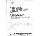
- FIG. 55A and 55B show the C code structure in Non-Patent Document 8 that cites the technique of Non-Patent Document 4.
- FIG. “Region3 ()” on the first line in FIG. 55A is a description of the execution operation of the machine language instruction in the specific address range. Each command will be described below.
- the “switch statement” on the third line in FIG. 55A branches to the case statement of the corresponding instruction address depending on the value of PC (program counter: ac_pc in the figure).
- Non-Patent Document 8 The C code optimization technique of Non-Patent Document 8 (see 5. Optimization Techniques of Non-Patent Document 8) is applied to the C code description by applying the following two optimization techniques. Note that these optimization methods have already been realized in the C code shown in Non-Patent Document 4.
- Optimization 1 optimization 1: In a normal instruction where the PC does not change discontinuously (branch, call, etc.), the next instruction becomes the immediately following case statement, so the useless break statement is deleted.
- Optimization 2 Updates the PC only when the PC changes discontinuously (branches, calls, etc.).
- Non-Patent Document 8 is said to be the fastest than the existing technology at that time, and yet it is reported that the simulation execution time is 14 to 54 times that of native execution.
- instruction set simulator source code problems relating to the C code of the instruction set simulator (hereinafter referred to as “instruction set simulator source code”) obtained by the methods of Non-Patent Documents 4, 8, and 9 will be described.
- Non-Patent Document 7 Page 3, right column, first paragraph:
- Each instruction of the decoded application corresponds to respective behavior function call in the generated simulator. These functions must be accessed randomly, as all of them can be a potential target of a jump instruction. ... The switch is based on the Program Counter.) Missing label information. Therefore, there is no information for determining which instruction can be a branch destination address. For this reason, based on the premise that “all” instructions can be branch destination addresses, a structure is required in which execution can transition directly from the switch statement to the instruction operation code of each case statement.
- simulation execution time is 14 to 54 times longer than native execution, so it is not practical to use the instruction set simulator source code for porting to another CPU because it involves a large overhead.
- the cause of the increase in simulation execution time comes from the switch statement related to the PC and the structure of the case statement corresponding to the address of each machine language instruction.
- a sixth problem is a lack of program control flow analysis.
- the instruction set simulation technology is focused on the part that implements the simulation function of the processor, and has a history of developing without sufficient cooperation with the compiler / decompiler technology. Therefore, there is no instruction set simulator that incorporates a program control flow analysis mechanism of compiler technology.
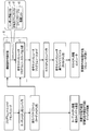
- FIG. 56 shows the programs of the conventional embedded system software development environment, and explain the merits and demerits of each case.
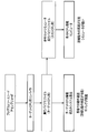
- FIG. 56 shows a software development environment for an embedded system that does not use a conventional instruction set simulator.
- software development environments for embedded systems that do not use an instruction set simulator include a target CPU embedded system product (actual machine) and a host CPU installed computer.
- the software development environment is a target CPU embedded system product (actual machine)
- the target CPU program source code or assembly code is converted into a machine language executable binary file by the target CPU compiler.
- the executable binary file is stored in the memory of the embedded system product with the target CPU.
- the software development environment is a computer with a host CPU
- the program source code or assembly code for the target CPU is converted into a machine language executable binary file by the host CPU compiler.
- the executable binary file is stored in a computer with a host CPU.
- the developed program source code or assembly code is incorporated into the host CPU-equipped computer and is not a real machine, so detailed operation cannot be reproduced.
- the host CPU-equipped computer since it is a computer with a host CPU, test cases for various conditions can be set, and debugging work for error correction is easy.
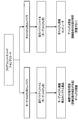
- FIG. 57 shows a software development environment for an embedded system using a conventional instruction set simulator.
- the program source code or assembly code for the target CPU is converted into a machine language executable binary file by the target CPU compiler.
- the execution binary file is converted into an execution binary file for the host CPU by an instruction set simulator.
- the execution binary file for the host CPU is executed on the computer with the host CPU. Since the execution binary file for the target CPU is converted to the execution binary file for the host CPU by the instruction set simulator, the detailed operation can be reproduced on the host CPU-equipped computer.
- the decompiler technology has the following problems. First, it is difficult to restore the data type. Second, it is difficult to analyze the program control flow of “indirect branching”. Third, it is difficult to restore function arguments and return values. Fourth, the source code output by the decompiler in terms of completeness has the following two problems. First, many existing decompilers cannot be made compilable without manual editing. As a second problem, programs that can be handled are limited due to the limitation of program complexity.
- Non-Patent Document 1 solves the problem that it is difficult to restore the first data type with a highly readable source output, and it is difficult to analyze the program control flow of the second “indirect branch”. Solves problems such as difficulty in restoring return values. However, the fourth integrity problem is unresolved.
- the instruction set simulator is satisfied with the fourth completeness that has not been solved by the decompiler technology.
- the instruction set simulator has a problem that it takes 14 to 54 times as much simulation time as the original program is directly executed by the host CPU (native execution).
- Non-patent documents 5 and 10 that output the machine language instructions of the target CPU directly as machine language instructions of the host CPU can realize a simulation time almost comparable to the native execution time.
- Non-Patent Documents 5 and 10 that output machine language instructions as other machine language instructions one platform cannot be ported to another platform, the program to be converted cannot be analyzed, virus detection, decoding, and analysis are not possible. There are problems such as being unable to do so.
- Non-Patent Documents 5 and 10 are problems that convert the decoding result of the machine language instruction into the C source code.
- the instruction set simulators of Non-Patent Documents 4, 8, and 9 have the following problems to be solved.
- the present invention was devised in view of the above circumstances, and can reliably restore a source program description file (instruction set simulator source code: C language description) from an execution binary and output a source program description file that can be easily analyzed.
- An object of the present invention is to provide an instruction set simulator that can construct a high-speed instruction set simulation environment and a simulator generation method thereof.
- An instruction set simulator is an instruction set simulator generated by converting a machine language program into a program source code, and includes a subroutine detection means for detecting a subroutine included in the machine language program, and the machine Branch instruction detecting means for detecting a branch instruction having a branch destination address among instruction words included in the word program, and subroutine calling for detecting a subroutine calling instruction having a subroutine call destination address among the instruction words included in the machine language program Instruction detection means, subroutine source code output means for outputting the program source code of each subroutine unit in which the machine language program is detected by the subroutine detection means, and an identifier indicating the branch destination address as the branch destination of the program source code Identifier adding means for adding to an instruction; unconditional branch instruction output means for outputting the branch instruction of the machine language program as an unconditional branch instruction to the instruction having the identifie
- the simulator generation method for the instruction set simulator of the ninth aspect of the present invention is a method for realizing the instruction set simulator of the first aspect of the present invention.
- the subroutine detecting means, the branch instruction detecting means, the subroutine calling instruction detecting means, and the identifier adding means are included, it is determined which instruction can be a branch destination address. It has information (solution of the first problem).
- a branch instruction of the machine language program is output as an unconditional branch instruction in the program source code, and a subroutine included in the machine language program is generated as a subroutine of the program source code.
- the hierarchical structure of the machine language program can be restored (solution of the fourth problem). Therefore, the compiler can be effectively optimized (solution of the third problem) and the processing speed is high (solution of the second problem). Also, the completeness of the instruction set simulator can be realized.
- the instruction set simulator is the simple branch instruction according to the first aspect, wherein the branch instruction detecting means detects a simple branch instruction that can specify a branch destination address among instruction words included in the machine language program. Instruction detecting means and data dependent branch instruction detecting means for detecting a data dependent branch instruction in which a branch destination address included in the machine language program is determined by a register value or a memory value.
- a simple branch instruction can be detected by the simple branch instruction detection means, and a data dependent branch instruction can be detected by the data dependent branch instruction detection means. It can be easily performed (solution of the first and sixth problems).
- an instruction set simulator for the second aspect of the present invention, the jump table recording means for recording a branch destination address of the data dependent branch instruction of the machine language program in a jump table information storage unit, and the jump Based on the branch destination address of the data-dependent branch instruction from the table information storage unit, the corresponding jump table information is retrieved, and the unconditional branch instruction of the program source code is retrieved using the retrieved jump table information.
- Data-dependent branch instruction generation means for generating.
- the simulator generation method for the instruction set simulator of the tenth aspect of the present invention is a method for realizing the instruction set simulator of the third aspect of the present invention.
- the unconditional branch instruction of the program source code can be generated smoothly and easily from the branch instruction of the machine language program using the jump table information (the first and sixth aspects). Solution of the problem).
- the subroutine call instruction detecting means detects a simple subroutine call instruction that can specify a call destination address among instruction words included in the machine language program.
- Simple subroutine call instruction detecting means and data dependent subroutine call instruction detecting means for detecting a data dependent subroutine call instruction in which a call destination address included in the machine language program is determined by a register value or a memory value.
- the simple subroutine call instruction can be detected by the simple subroutine call instruction detecting means
- the data dependent subroutine call instruction can be detected by the data dependent subroutine call instruction detecting means
- the subroutine call instruction in the program source code can be detected. It can be generated smoothly and easily (solution of the first and sixth problems).
- the instruction set simulator according to the fourth aspect, wherein the subroutine call instruction output means generates a subroutine machine language address table relating to information in which a subroutine name and a subroutine machine language address are paired.
- Address table generation means subroutine address search processing instruction generation means for generating a subroutine address search processing program for searching a subroutine on the program source code from a subroutine machine language address and obtaining a subroutine address on the program source code;
- the data dependence for performing the process of specifying the subroutine called the data dependent subroutine calling instruction of the program source code by the subroutine address search processing instruction and calling the subroutine And a subroutines call instruction generation unit.
- the eleventh instruction set simulator generating method of the present invention is a method for realizing the fifth instruction set simulator of the present invention.
- An instruction set simulator is the instruction set simulator according to any one of the first to fifth aspects, wherein the register value of the machine language program is described as a subroutine argument variable or a local variable on the program source code. Register variable expansion means.
- the simulator generation method for the instruction set simulator of the twelfth aspect of the present invention is a method for realizing the instruction set simulator of the sixth aspect of the present invention.
- the register variable expansion means describes the register value of the machine language program as a subroutine argument variable or a local variable on the program source code (the third and fourth variables). Therefore, the processing speed of the instruction set simulator can be increased (solution of the second problem).
- an instruction set simulator according to any one of the first to fifth aspects of the present invention, wherein the program source code is a C language program and relates to a switch statement relating to a program counter and each instruction address.
- An unconditional branch instruction and a subroutine call instruction to an instruction having an identifier on the program source code are used without using the code structure of the case statement, and the subroutine of the machine language program and the subroutine of the program source code are The subroutine hierarchy in the machine language program is restored to the subroutine hierarchy in the program source code.
- the program source code is a C language program, and does not use the code structure of the switch statement relating to the program counter and the case statement relating to each instruction address. Since an unconditional branch instruction to an instruction having an identifier and a subroutine call instruction are used, optimization can be performed effectively. Also, the subroutine of the machine language program and the subroutine of the program source code correspond to each other, and the subroutine hierarchy in the machine language program is restored to the subroutine hierarchy in the program source code (solution of the fourth problem). Can be effectively implemented (solution of the sixth problem), and the processing speed of the instruction set simulator is high (solution of the second problem). In addition, the program source code is highly readable and easy to analyze. Therefore, it is possible to easily analyze malware, viruses, etc. (solution of the fifth problem).
- the instruction set simulator of the eighth aspect of the present invention is the same as any one of the first to fifth aspects of the present invention, since the symbol information is missing in the machine language program.
- a machine language address that is not registered in the subroutine machine language address table is called by a data dependent subroutine instruction
- the instruction set is recorded after the unregistered machine language address is recorded.
- the thirteenth instruction set simulator generation method of the present invention is a method for realizing the eighth instruction set simulator of the present invention.
- an instruction set simulator capable of reliably restoring a source program description file from an execution binary, outputting a source program description file that can be easily analyzed, and constructing a high-speed instruction set simulation environment, and a method for generating the simulator. Can be provided.
- the figure which shows the sample of C source code The figure which shows the assembly instruction disassembled with the hexadecimal display of the address of each machine language instruction, and a 32-bit machine language instruction.
- the functional block diagram of a data dependence branch information extraction part The figure which shows the machine language instruction and assembly instruction of the ARMv5 instruction set of the jump_test function of FIG.
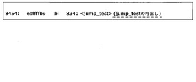
- the figure which shows 4 instructions of ARMv5 instruction set machine language and assembly description of the "jump_test" function of FIG. The figure which shows the macro call description with respect to the four ARMv5 instruction set machine language instructions of FIG.
- generation macro calls of FIG. The functional block diagram of a subroutine program source production
- the figure which shows the program description of a subroutine call instruction The figure which shows a conditional data dependence branch instruction and the unconditional branch instruction immediately after.
- the figure which shows the program description of a data dependence subroutine call instruction The figure which shows the output of the program description corresponding to the machine language instruction description of the "jump_test" function of FIG.
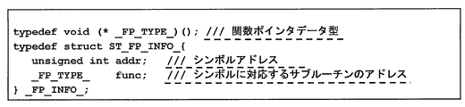
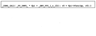
- the figure which shows the _FP_INFO_ structure which stores symbol address information.
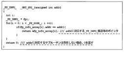
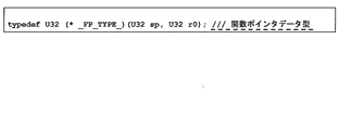
- the figure which shows the definition of _GET_FPI_ function which returns the pointer of _FP_INFO_ structure.
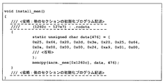
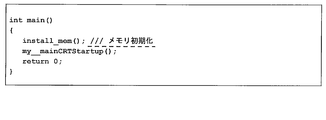
- the figure which shows the example of a memory initialization program description The figure which shows the example 1 of a program description of the highest function of an instruction set simulator.
- the figure which shows the program description which writes the argument information of the main function in CPU memory The figure which shows the functional block diagram of the machine language instruction analysis part of 2nd Embodiment.
- the figure which shows the input / output register of the ARMv5 machine language instruction of the "jump_test” function of FIG. The functional block diagram of a subroutine argument extraction part.
- the figure which shows the subroutine definition description output of a "jump_test” function The figure which shows the program description of a subroutine call instruction.
- the figure which shows the program description of a data dependence subroutine call instruction The figure which shows the software development environment for embedded systems using the instruction set simulator of 3rd Embodiment.
- the figure which shows the C code structure in the nonpatent literature 8 which quoted the method of the nonpatent literature 4.
- the figure which shows the software development environment for embedded systems which does not use the conventional instruction set simulator.
- the instruction set simulator of the present invention is an application of a program flow control analysis function and a data dependency analysis function, which have been constructed by a decompilation technique, to a Static compile method.
- the “completeness” of the instruction set simulator technology is secured, and the simulation speed can be improved to the same level as native execution.
- certain readability of the restored source code is ensured.
- “completeness” means that an executable binary can be “reliably” executed such that any program can be reliably simulated.
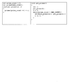
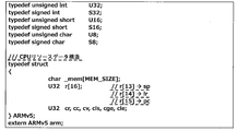
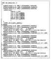
- Figure 1 shows a sample C source code.
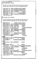
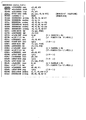
- Fig. 2 shows the C source code sample shown in Fig. 1 converted into machine language instructions in the ARMv5 instruction set of an embedded processor using C Compiler (gcc: GNU Compiler Collection).
- FIG. 2 shows the assembly instruction disassembled with the address of each machine language instruction and the hexadecimal representation of the 32-bit machine language instruction.
- the left four alphanumeric characters are the instruction address
- the middle eight alphanumeric characters are the hexadecimal machine language instructions
- the right is the assembly instruction.
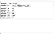
- the features of the ARMv5 instruction set shown in Figure 2 are as follows: • 16 registers (r0, ..., r9, sl, fp, ip, sp, lr, pc): The program counter (pc) can be rewritten with normal instructions. Various program control can be realized by various instructions for updating pc.
- Execution condition All instructions include a 5-bit execution condition flag, and if the execution condition is not met, execution is skipped.
- popgt, beq suffix ble instruction (gt, eq, le) is execution condition (g reater t han, eq ual , l ess or e qual) is, execution conditions suffix no instruction is always executed (Al: al ways).
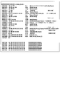
- a “constant pool” embedded in the program area is used as a mechanism for loading 32-bit immediate values (constants) into registers.
- the data (0x1b308, 0x1b404, 0x1b308) at each address of 0x8234, 0x8238, and 0x8428 corresponds to the constant pool.
- These constants are loaded by load instructions (0x8218, 0x8220, 0x83c4) with pc as the base address.
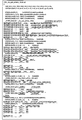
- FIG. 3 shows a C source description output by this embodiment. The characteristics of the C source description output by the instruction set simulator of this embodiment will be described below.
- one machine language instruction has one-to-one correspondence with one C macro call instruction (LDR, ADD, CMP, etc.). That is, there is basically a feature that sequential processing is performed in the order of description of machine language source code. The actual instruction behavior is defined inside each C macro description. (Non-Patent Document 4 also uses the same C macro description: see FIGS. 53 and 54)
- the second feature is that the function of the original C source code (FIG. 1) and the function of the C description generated from the execution binary by the instruction set simulator of this embodiment have a one-to-one correspondence. That is, the function hierarchy of the original C source code is restored as it is to the C source description output by the instruction set simulator S of the present embodiment.
- a function argument for example, r0
- a parameter name corresponding to the CPU register.
- Other CPU registers that do not appear in function arguments are declared as function local variables. 3, r0, r1,..., R9, sl, fp,..., Pc are CPU general-purpose register variables (local variables), and cv, cc, ..., cle are CPU status register variables (described later).
- the stack pointer (sp) is passed as a function argument.
- the function return value is passed through the register (r0 in the above example) specified by the function call rules (compiler dependent) (line 12 in FIG. 3). Even if the original C function is a void type (a function with no return value), a description that passes r0 is output, but there is no problem in program operation. This is because the compiler assumes that the value of r0 is rewritten before and after the function call, so there is no problem even if a return value of “empty” (undefined value) is assigned to r0.
- the third feature is that a C label (L_083f0, L_083fc, L08400, etc.) (identifier) (identifier) is placed before the branch destination instruction, and the branch instruction is described by a goto statement of an unconditional branch instruction.
- the program control flow of the executable binary can be expressed as it is in the C language description.
- ⁇ Instruction set simulator execution time The characteristics of the C source code structure according to the present embodiment (the present invention) can be confirmed by actually compiling and executing the C source code by the instruction set simulator of the present embodiment.
- the internal structure of the C macro that appears in the C source code in Fig. 3 is composed of fairly complex code in order to faithfully express complex CPU operations with C language descriptions.
- This section describes how the C source code output by this instruction set simulator generates efficient execution code (execution binary of the host CPU) despite the C description of complex CPU operations.
- the host CPU refers to a processor (such as a processor mounted on a desktop notebook PC) that executes a software tool such as an instruction set simulator.
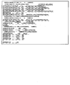
- FIGS. 4A and 4B show the C description output of the execution binary according to the present invention and the machine language instruction of the recompiled host PC (X86 instruction set) superimposed on each other.
- the part enclosed by the ruled lines in FIGS. 4A and 4B is the machine language instruction of the recompiled host PC (X86 instruction set).
- a prime number calculation program including the code shown in Fig. 2 of the test program Host CPU: Intel Xeon 3.4GHz (Quad core), 3.25GB memory
- native execution time was 0.7580 seconds.
- the simulation execution time of the prime number calculation program including the code of FIG. 2 of the test program by the instruction set simulator S of the present embodiment (the present invention) is 0.7699 seconds, and the ratio of the native execution time: 0.7580 seconds It was 1.016 times.
- FIG. 5 shows a software development environment for an embedded system using the instruction set simulator of the first embodiment.
- the target CPU refers to a processor (such as a processor installed in an embedded system) that executes an execution binary machine language instruction.
- the host CPU refers to a processor that executes a software tool such as an instruction set simulator. For example, it refers to a processor mounted on a desktop notebook PC.
- the program source code or assembly code for the target CPU is converted into an execution binary file for the target CPU by the target CPU compiler.
- the execution binary file is stored and executed in the memory of the embedded system product with the target CPU.
- the machine language instruction analysis unit 1 of the instruction set simulator S When simulating with the instruction set simulator S, the machine language instruction analysis unit 1 of the instruction set simulator S reads the execution binary file for the target CPU, executes the machine language instruction analysis process, and executes the symbol information list r1, branch destination address list Outputs r2 and jump table information list r3.
- the program source code output unit 2 of the instruction set simulator S reads the execution binary file for the target CPU, the symbol information list r1, the branch destination address list r2, and the jump table information list r3. Then, the program source code output unit 2 outputs an instruction set simulator program source code (program set code of the instruction set simulator S).
- the instruction set simulator program source code corresponds to the C language source code described above.
- the instruction set simulator program source code is converted into an execution binary file for the host CPU by the host CPU compiler.
- the execution binary file for the host CPU is loaded into the memory of the computer with the host CPU and executed.
- the instruction set simulator S is realized using software. Note that at least a part of the instruction set simulator S may be configured by hardware.
- program execution binary data machine language data
- OS compiler language data
- storage position refers to an offset value from the beginning of the ELF file
- position stored in the ELF file is designated by the number of bytes.
- ELF header Located at the beginning of the ELF file, it contains all the information necessary to obtain various data stored in the ELF.
- the main items are as follows.
- the file type is an executable file, a linkable file, a shared library, or the like.
- CPU model / version entry point (first address when executing a program), storage location of the program header table, ELF header size of the storage location of the section header table, size and number of entries of one entry in the program header table, section There are a size and the number of entries of one entry of the header, a section header table index storing a section name character string table, and the like.
- the program header table includes information necessary for the OS and the like to prepare for memory area reservation and memory initialization when the ELF file is executed by the CPU.
- An entry contains as a main item the following information about one segment (consisting of one or more sections):
- the segment type includes a readable segment and a dynamic link segment.
- there are a storage location of the segment a virtual address and a physical address at which the segment is arranged on the memory, a file size and a memory size of the segment, a segment access right (combination of executable, readable, and writable).
- the binary data part stores machine language instruction data (program memory data) and initial value data of the data memory.
- Section header table A section exists as a constituent unit of a memory area (program memory / data memory) and as a storage unit of supplementary information.
- One entry in the section header table contains the following information about one section as the main items.
- As the section name string information there is an index to the section name string table section in the section header.
- the section type includes program definition information (memory area constituent unit, debug information, etc.), symbol table (program address information, variable address information), character string table, relocation information, dynamic link information, and the like.
- the section attributes include memory area occupation (readable), writable, executable, and the like.
- Symbol table A symbol mainly includes program address information and variable information stored in a memory, and belongs to any section.
- the symbol table is stored as one entry in the section header table.
- the symbol contains the following information as main items.
- symbol name character string information there is an index to the “symbol name character string table” in the section header.
- symbol name character string table There is the memory address of the symbol and the size of the symbol.
- type attribute an attribute of a symbol associated with a function or another executable instruction is referred to as “FUNC type”.
- section index there is an index of a section to which the symbol belongs.
- ELF header item Address where the first instruction to be executed after program startup is stored
- the address area of the segment with “executable” access right is defined in the program header table.
- the address area of the section with the “executable” attribute is defined in the section header table.
- the memory address of the symbol included in the address area of the section having the “executable” attribute is defined in the symbol table defined in the section header table.
- the information that is guaranteed to be defined in the executable file is the address area of the entry point and executable segment, and the section header table can be omitted, so section information and symbol information may be missing. possible.
- symbol information list has a “symbol information” list structure. “Symbol information” stores information items of symbol addresses and instruction address lists regarding executable symbols. (A) Symbol address (B) Instruction address list: It has a list structure of addresses of all instructions reachable from the symbol address.
- Instruction address temporary list Instruction addresses that store the machine language instructions to be processed and are updated as the processing of the machine language instruction analyzer 1 proceeds (the instruction addresses to be processed are read and deleted) It has a list structure of
- Branch Destination Address List has a list structure of branch destination addresses of conditional branch instructions and unconditional branch instructions.
- next instruction information temporary list has a list structure of “next instruction information”. “Next instruction information” is information regarding an instruction (hereinafter referred to as “next instruction”) that can be executed after a certain instruction is executed, and includes the following data items.
- next instruction address B) The next instruction type is one of the following three types.
- “Jump table information list r3” a list structure of “jump table information”.
- the “jump table information” is information generated by “processing of the data dependent branch information extraction unit 2” described later, and includes the following data items.
- C) Branch destination address table (one entry stores a branch destination address. “Number of entries” “jump table size”)
- FIG. 7 shows a functional block diagram of the machine language instruction analysis unit of the first embodiment.
- the machine language instruction analysis unit 1 of the first embodiment has a role of analyzing a machine language in order to convert a machine language to be analyzed executed by the target CPU into a C code.
- the machine language instruction analysis unit 1 includes a symbol address preprocessing unit 1a, a symbol address acquisition unit 1b, an instruction address acquisition unit 1c, a next instruction information extraction unit 1d, an address list update unit 1e, and a data dependent branch extraction unit 2. ing.
- the machine language instruction analysis unit 1 outputs a symbol information list r1, a branch destination address list r2, and a jump table information list r3 in order to create a C code from the machine language to be analyzed.
- a process of the machine language instruction analysis unit 1 of the first embodiment a process flow when a premise that a section header table exists and a symbol table is defined therein will be described.
- the symbol address preprocessing unit 1a creates a “symbol address temporary list”.
- the symbol address preprocessing unit 1a is a symbol included in an address area of a section having an executable attribute in a symbol table defined in the section header table, and is associated with a function or another executable instruction. Symbols with attributes (see “FUNC type symbol type attributes” above) are considered “executable symbols”.
- the symbol address preprocessing unit 1a creates a “symbol address temporary list” by “adding” all addresses of “executable symbols” to the “symbol address temporary list”. Thereafter, the process proceeds to the symbol address acquisition unit 1b.
- the “symbol information” regarding the current symbol does not exist in the “symbol information list”
- the “symbol information” of the extracted current symbol is generated as follows. This symbol information is hereinafter referred to as “current symbol information”. 1) Set the “current symbol” address in “symbol address” of “symbol information”. 2) Generate “symbol name string”. When the symbol is registered in the “symbol table”, the “symbol name character string information” in the “symbol table” is acquired and generated.
- next instruction information extraction unit 1d reads binary data stored in the “binary data part” of the “execution binary file” based on the “current instruction address”, and regards this binary data as a machine language instruction. Then, the next instruction information extraction unit 1d decodes (interprets) the machine language instruction, executes the following processes (1) to (4) corresponding to the instruction type, and generates “next instruction information”. “Add” to the “next command information temporary list”.
- next instruction information extraction unit 1d In the case of a “simple branch instruction” (a branch instruction whose branch destination address can be specified only by an instruction word), the next instruction information extraction unit 1d generates “branch type” next instruction information from the branch destination address.
- a “data dependent branch instruction” a branch instruction whose branch destination address is determined by a register value / memory value
- the branch destination cannot be specified directly by the instruction word alone, so the following processing is executed.
- “data dependent branch information extraction unit 2” described later is executed to extract “jump table information” from the jump table information list r3.
- the next instruction information extraction unit 1d generates “branch type” next instruction information for all branch destination addresses stored in the “branch destination address list r2” of the extracted “jump table information”.
- next instruction information extraction unit 1d In the case of a “simple subroutine call instruction” (subroutine call instruction whose call destination address can be specified only by an instruction word), the next instruction information extraction unit 1d generates “call type” next instruction information from the call destination address. (4) In the case of “data dependent subroutine call instruction” (subroutine call instruction whose call destination address is determined by the register value / memory value), the next instruction information extraction unit 1d selects “data dependent subroutine instruction” of “current symbol information”. “Flag” is set to “1”. The call destination address of the “data dependent subroutine call instruction” is resolved by another means described later.
- Instructions that may execute “immediate instruction” are all instructions except for the following cases.
- ⁇ Address list update unit 1e> Various address lists are updated from the “next instruction information temporary list” generated by the next instruction information extraction unit 1d as follows. (1) Updating by “next type” next instruction information “takes out” all “next type” next instruction information from “next instruction information temporary list” and adds them to the instruction address temporary list. (2) “Branch type” next instruction information is updated by “fetching” all the “branch type” next instruction information from the “next instruction information temporary list”, into the branch destination address list r2 and the instruction address temporary list. "to add.
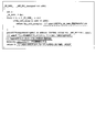
- FIG. 8 shows a sample C program of the function jump_test including the switch statement.
- the switch statement switch (n) [case 3:... case 8:... default:...]
- the jump_test function is implemented as a data-dependent branch instruction regarding the value of the variable n.
- the data dependent branch instruction operates by preparing the following instruction elements and data elements in advance.
- Jump table An address table that stores the head instruction address corresponding to each case statement in the switch statement.
- the first instruction address corresponding to case min_case_value: is stored in the first entry of the jump table.
- the last entry stores the first instruction address corresponding to case max_case_value :.
- the head instruction address corresponding to the default statement is stored if the default statement exists, and the default statement does not exist The head instruction address immediately after the switch statement is stored.
- Conditional branch instruction based on jump table offset value range determination A conditional branch instruction that branches when the range determination result is “false”.
- the branch destination address at this time is the first instruction address corresponding to the default statement when the default statement exists, and the first instruction address immediately after the switch statement when the default statement does not exist.
- Jump table storage memory read instruction and data-dependent branch instruction When the jump table offset value range judgment result is “true”, the memory address jt_addr where the jump table is stored is (jt_addr + jt_offset * a_size The data-dependent branch destination address stored in the memory address calculated in step) is read.
- a_size is the word length (byte length of the word size) of the address value, and is 4 (bytes) for a 32-bit instruction set and 8 (bytes) for a 64-bit instruction set.
- PC program counter
- the jump table storage memory read instruction and the data dependent branch instruction may be implemented as a single machine language instruction (ARMv5 instruction set, x86 instruction set, etc.).
- Jump table offset value range determination instruction (2) Conditional branch instruction by jump table offset value range determination (3)
- Jump table storage memory read instruction (4)
- Data dependent branch instruction (3), (4 ) May be one machine language instruction (described above). (2) may come immediately after (4).
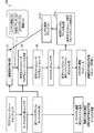
- FIG. 9 shows a functional block diagram of the data dependent branch information extraction unit.
- the data dependent branch information extraction unit 2 performs the following series of processes. Assume that the address of the data dependent branch instruction has already been given by the next instruction information extraction unit 1d (FIG. 7).
- (1) “Jump table storage memory read command” extractor 2a When the data dependent branch instruction itself performs a memory read, this instruction is a “jump table storage memory read instruction”. In the case of a data-dependent branch instruction that assigns a register value to a PC, an instruction that loads a memory into a register before the data-dependent branch instruction is executed is a “jump table storage memory read instruction”.
- Jump table storage memory address analysis unit 2b and jump table offset register extraction unit 2c In the jump table storage memory read instruction, when the memory address is calculated in the format of “base address value (fixed address) + offset value”, the “base address value” is specified as “jump table storage memory address value”, The register for storing the offset value is specified as “jump table offset register”.
- base address value is given as an “absolute address” (information of the address value itself is specified by a machine language instruction) and a “PC relative address” (an offset value added to the current instruction address is a machine language). May be calculated as specified by the instruction).
- Branch destination address information reading part 2f All the branch destination addresses stored in the jump table are read from the information of the “jump table storage memory address value” and “jump table size” specified above, and stored in the branch destination address table (machine language address table).
- Jump table information generator 2g Generates “data dependent branch jump table information” consisting of “data dependent branch instruction” given in advance and “jump table size” and “branch destination address table” obtained in steps (1) to (4) above. And “add” to the “data dependent branch information list”. The information of the generated data dependent branch jump table is used in the next instruction information extraction unit 1d.
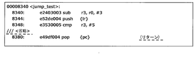
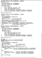
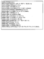
- FIG. 10 shows machine language instructions and assembly instructions of the ARMv5 instruction set of the jump_test function of FIG. Each line is written in the order of "instruction address" (hexadecimal notation), "machine language instruction data” (hexadecimal notation), and "assembly instruction description". For instructions that affect the PC (program counter), The instruction type is also shown. In the following description, the subsequent machine language instruction analysis processing will be described on the assumption that the address “0x8340” of “jump_test” is acquired from the “symbol address temporary list”.
- Table 1 shows the machine language instruction analysis processing from 0x8340 to 0x834c.
- next instruction information is sequentially extracted based on the instruction of the symbol address 0x8340. Since each instruction of 0x8340, 0x8344, and 0x8348 is a “normal instruction” that does not affect the PC, only the “immediate instruction” is the next instruction. These next instruction addresses are “added” to the “instruction address temporary list” by the address list update unit 1e, and then immediately fetched by the instruction address acquisition unit 1c. B) Since the instruction of 0x834c is a “data-dependent branch instruction”, the next instruction information extraction process of this part is performed in the data-dependent branch information extraction unit 2.
- Table 2 shows the processing of the data dependent branch information extraction unit 2 at 0x834c.
- the data dependent branch information extraction unit 2 firstly specifies that the “jump table storage memory read instruction” at 0x834c is the same as the data dependent branch instruction, from which the jump table storage memory address is 0x8354, and the jump table size is 6 is identified. Finally, six branch destination addresses [0x8384, 0x839c, 0x836c, 0x83a4, 0x836c, 0x8384] are read from address 0x8354 to generate “jump table information”.
- Table 3 shows the process of the 0x834c next instruction information extraction unit 1d and the process of the 0x8350 machine language instruction analysis unit 1.
- next instruction information temporary list is also generated as the next instruction for the immediately following instruction (0x8350).
- the six branch destination addresses include duplicate addresses, duplicate next instruction information is not added to the next instruction information temporary list.
- the address list update unit 1e four (non-overlapping) branch destination addresses are “added” to the “branch destination address list”, and five next instruction addresses (branch type / immediate type) are added to the “instruction address temporary list”. Added. "
- the instruction address acquisition unit 1c “takes out” the last address 0x8350 of the instruction address temporary list. Since this instruction is an “unconditional branch instruction”, the next instruction information extraction unit 1d extracts the branch destination address 0x839c as the next instruction address. Then, the address list updating unit 1e adds the branch destination address 0x839c to the “branch destination address list” and the “instruction address temporary list”. Here, since 0x839c exists in any list, these lists are not updated.
- Table 4 shows the machine language instruction analysis processing from 0x83a4 to 0x83b4.
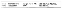
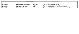
- Table 5 shows 0x83ac, 0x83a8 machine language instructions and C language instructions.
- 0x83ac is a “data-dependent branch instruction” that jumps to the value of register r3, but an instruction that assigns pc (actual value is the current instruction address 0x83a8 + 8) to link register lr immediately before 0x83a8 Therefore, it can be determined that the instruction of 0x83ac is actually a “data dependent subroutine call instruction”.
- variable f is a function pointer (variable)
- f (n) is a subroutine call via the function pointer is there.
- jump table information in “data dependent branch instruction” is fixed data in memory and can be extracted
- call destination address in “data dependent subroutine call instruction” is program execution In general, it is difficult to extract a callee address.
- next instruction information of the data dependent subroutine call instruction is only “immediate instruction”, and the resolution of the data dependent subroutine call destination address is handled by another means described later. That is, the next instruction information extraction process of the “data dependent subroutine call instruction” is handled in the same manner as the “normal instruction”.
- Table 6 shows the machine language instruction analysis processing of other parts.
- the end address 0x8384 of the temporary instruction address list is taken and the next instruction (immediate instruction) address is continuously analyzed from the instruction at address 0x8384.
- a return instruction of 0x8398 (no next instruction) is reached.
- the instruction address acquisition unit 1c detects that the "instruction address temporary list” is “empty” (all instruction analysis within the symbol has been analyzed), and the “instruction address list” in the "current symbol information” "Is sorted in ascending order.
- FIG. 11 shows machine language instructions and assembly instructions of the x86 (64-bit) instruction set of the jump_test function. From the left, each line is "instruction address" (6-digit hexadecimal notation), “machine language instruction data” (separated by 2 hexadecimal digits in order from left to right), “assembly instruction description” It is written in order. In addition, about the instruction
- Table 7 shows the processing of the machine language instruction analysis processing unit 1 up to 0x400560-0x40056e of the jump_test function of FIG.
- next instruction information is extracted sequentially based on the instruction at symbol address 0x400560, and each instruction at 0x400560, 0x400563, 0x400567 is a "normal instruction” that does not affect the PC, so "immediate instruction” Only becomes the next instruction.
- the instruction at 0x40056a is a “conditional branch instruction”
- the branch destination address 0x400575 and the immediately following instruction address 0x40056c are the next instruction addresses.
- the instruction at 0x40056e is a “data dependent branch instruction”
- the processing of the next instruction information extracting unit 1d in this part is performed by the data dependent branch information extracting unit 2.
- Table 8 shows the data-dependent branch information extraction process at 0x40056e in FIG.
- the “jump table storage memory read instruction” is the same as the data-dependent branch instruction, from which it is specified that the jump table storage memory address is 0x400738 and the jump table size is 6. .
- six branch destination addresses [0x400591, 0x400575, 0x400580, 0x40059a, 0x400580, 0x400591] are read from the address 0x400738, and “jump table information” is generated.
- Table 9 shows the next instruction information extraction process of 0x40056e.
- Six branch destination addresses are acquired from the jump table information generated by the data dependent branch information extraction unit 2 for the instruction of 0x40056e, and a next instruction information temporary list is generated.
- the six branch destination addresses include duplicate addresses, duplicate next instruction information is not added to the next instruction information temporary list.
- the address update unit four (non-overlapping) branch destination addresses are “added” to the “branch destination address list r2” and “instruction address temporary list”, but the next instruction address 0x400575 exists in both lists. Actually, three addresses are added.
- Table 10 shows the process of the machine language instruction analysis unit 1 in other parts. Immediately before 0x40059a, the instruction address list and the instruction address temporary list are as shown in the upper column of Table 10.
- Instruction address to be analyzed in column D of Table 10 (0x400575, 0x400577, 0x40057b): The last address 0x400575 of the instruction address temporary list is taken, the next instruction address (immediate type) is continuously analyzed, and the return instruction (0x40057b) No next command is reached.
- the “Instruction Address Acquisition Unit 1c” detects that the “Instruction Address Temporary List” is “Empty” (all instructions in the symbol are analyzed), and the “Instruction Address List” in “Current Symbol Information” "Is sorted in ascending order.
- FIG. 12 shows the configuration of the instruction set simulator together with the execution binary file to be analyzed and the instruction set simulator program source code output from the instruction set simulator.
- the instruction set simulator S includes a machine language instruction analysis unit 1 and an instruction set simulator program source code output unit 3.
- the instruction set simulator program source code output unit 3 outputs the instruction set simulator program source code from the symbol information list r1, the branch destination address list r2, and the jump table information list r3 having the information extracted by the machine language instruction analysis unit 2. To generate.
- the instruction set simulator program source code output unit 3 includes a subroutine program source generation unit 3a, a symbol address information table source generation unit 3b, a memory initialization program description generation unit 3c, and a main function program description generation unit 3d. ing.
- the instruction set simulator program source code 4 includes a subroutine program source 4a, a symbol address information table source 4b, a main function source 4c, a memory initialization processing source 4d, and a machine language instruction program generation macro definition source 4e prepared in advance. Have.
- CPU resource refers to memory and CPU registers (general-purpose registers, internal status registers, etc.), and the state of these “CPU resources” is true to the CPU operation as actual hardware on the instruction set simulator program. Must be reproduced on the simulator program.
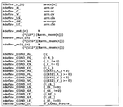
- FIG. 13 shows an example of the data structure description of the CPU resource in the ARMv5 instruction set simulator program
- FIG. 14 shows the CPU resource reference macro definition and the instruction execution condition determination macro definition.
- Memory Declared as an array of char type (8 bits).
- MEM_SIZE memory size specifies a necessary memory size (reserving a necessary stack area) from information obtained from a “program header table” included in the execution binary file.
- Status register Declared as six 32-bit variables (unsigned) consisting of cr, cc, cv, cls, cge, and cle. These are used as information indicating the state of the CPU for determining the “instruction execution condition” in the ARMv5 instruction.
- a mechanism that usually determines 14 execution conditions based on a combination of four internal register bits (Z: zero, N: negative, V: overflow, C: carry) Is implemented. It is also possible to realize the same 4-bit status register as a resource description, but here, by declaring it as six 32-bit variables, it is possible to determine the "instruction execution condition" on the software. It is intended to reduce the amount of calculation (described later).
- Instruction execution condition determination by the above six status register variable reference macros is performed on the program description. There are 15 types of instruction execution conditions as follows. (The following is a comparison between the condition determination condition of the normal Z / N / V / C 4-bit status register and the condition determination expression based on the six status register variable reference macros in FIG. 14)
- the “machine language instruction program generation macro” is a programming description technique having a function of partially generating an execution program description based on several arguments (variables, constants, character strings).
- machine language instruction program macro is defined for each type of machine language instruction used (the macro definition is, of course, a description specific to the instruction set of the target CPU).
- the machine language instruction program generation macro definition source 4e is prepared in advance because it is information that does not depend on the “execution binary file” to be analyzed.
- FIG. 16 shows a “machine language instruction program macro” call description corresponding to the four machine language instructions shown in FIG. Hereinafter, each machine language instruction program macro will be described.
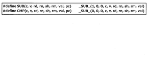
- FIG. 17 shows the SUB macro definition and the CMP macro definition.
- the SUB macro is called in response to the sub instruction, and the CMP macro is called in response to the cmp instruction.
- (2) _SUB_ macro shown in FIG. 18 Internal macro further called by the SUB macro and the CMP macro.
- the meanings of the arguments used in the SUB macro and CMP macro are as follows.
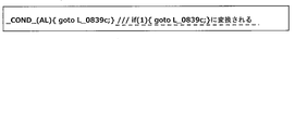
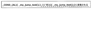
- _COND_ macro An internal macro further called by the _SUB_ macro, which is defined in FIG. “_COND_ (c)” is macro-defined as “if _COND _ ## c ## _”. Since “##” is a “character string concatenation preprocessor”, for example, _COND_ (AL) is converted to “if _COND_AL_”, and “_COND_AL_” is further converted to “(1)” by the macro definition.
- FIG. 19 shows another macro called inside the _SUB_ macro.
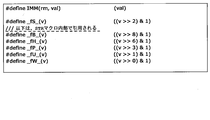
- IMM (rm, val) In the SUB macro call and the CMP macro call in FIG. 16, “IMM” is given as the macro argument sh.
- sh The description of “sh (rm, val)” in FIG. 18 is converted into “IMM (rm, val)”, and finally converted into “(val)” in this IMM macro definition.
- -_FS_ (v) converted to ((v >> 2) & 1).
- this is equivalent to an operation for extracting the lower 2 bits of v (counting from the 0th bit).
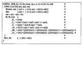
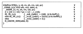
- FIG. 20 shows the STR macro definition called in FIG. 16, and FIG. 21 shows the _ADDR_, _D_CACHE_SIM macro definition called inside the macro.
- FIG. 21 shows the _ADDR_, _D_CACHE_SIM macro definition called inside the macro.
- push [lr] in the assembly instruction description in the original machine language, this means that the stack pointer sp (arm.r [13]) is decremented (1 data (This is implemented as a str instruction in ARMv5, which writes the link register lr (arm.r [14]) to the memory using the value obtained by subtracting the address of the word) as the memory address.
- _ADDR_ macro This is called inside the STR macro and generates the following program that calculates the memory write address. Macros _fU_ (v), _fP_ (v), and _fW_ (v) called from _ADDR_ are instruction attributes that specify an address offset calculation method, whether or not the base address register _r_ (rn) is updated, and the like.
- D_CACHE_SIM macro provides a mechanism to call the data cache simulation function D_Cache_Sim (defined separately) (see Figure 21) when cache simulation is enabled (when ENABLE_CACHE_MODEL is defined separately). . If the cache simulation is not valid, the description of D_CACHE_SIM (addr, isRead) (see FIG. 21) is converted to “empty character string”.
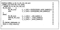
- FIG. 22 shows the LDR macro definition called in FIG. (Supplement: Although it is “pop [pc]” in the assembly instruction description of the original machine language, this is recorded in the above push [lr] with the stack pointer sp (arm.r [13]) as the memory address. The read “return instruction address value” is read from the memory, and the stack pointer is "incremented” (adds an address for one data word), and is implemented as an ldr instruction in ARMv5.)
- Subroutine naming rules in program description The “subroutine naming rules” in the program description of the subroutine program source 4a shown in FIG. 12 will be described.
- the points to be noted in the subroutine naming rules are that, for example, in the C language, a subroutine name having a special meaning is reserved, such as the main function and the exit function, so it is necessary not to duplicate the reserved subroutine name. .
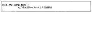
- a predetermined “prefix character string” (for example, “_my_”, etc.) is concatenated to the head of the “symbol name character string” included in the “symbol information” to be a “subroutine name character string”.
- the “subroutine name character string” corresponding to the symbol name “jump_test” is “_my_jump_test” when the “prefix character string” is “_my_”.
- the symbol name generation rule is generated as described above.
- the same “prefix character string” may be used.
- the subroutine name character string may be “_my_func_1234”.
- Subroutine program source generation unit 3a (FIG. 24) that generates a subroutine program source including a machine language instruction program generation macro call description as shown in FIG. 16 will be described.
- ⁇ Subroutine information acquisition unit 3a1> One symbol information is extracted from the symbol information list r1 generated by the machine language instruction analysis unit 1.
- the symbol information extracted here is referred to as “current symbol information”.
- ⁇ Subroutine definition description generator 3a2> Based on the “subroutine name character string” included in the “current symbol information”, a “subroutine definition description” as shown in FIG. 25 is generated. In the “first embodiment”, a description of a subroutine definition that has no return value (void type) and takes no arguments is generated.
- the instruction address acquisition unit 3a3 sequentially reads out “instruction addresses” from the head of the “instruction address list” of “current symbol information”.
- the read “instruction address” is hereinafter referred to as “current instruction address”.
- the “branch destination address list” obtained by the machine language instruction analysis processing of the jump_test function of the ARMv5 instruction set is [0x8384, 0x839c, 0x836c, 0x83a4] (see Table 3).
- the C language label descriptions corresponding to these branch destination addresses may be generated as, for example, “L_08384:”, “L_0839c:”, “L_0836c:”, “L_083a4:”.
- the machine language instruction type determination unit 3a5 reads binary data stored in the “binary data part” of the “execution binary file” based on the “current instruction address”.
- the binary data is regarded as a machine language instruction, and the machine language instruction is decoded (interpreted) (the same procedure as the machine language instruction decoding process of the next instruction information extraction unit 1d) to determine the following instruction types.
- -Instruction type Specifies a machine language instruction program generation macro name. This is information for generating macro names such as SUB, STR, CMP, LDR in FIG.
- Action register number Specify the operand register number and operation result storage register number.
- the following corresponds to the action register number: SUB (AL, 0x020, 3, 0, IMM, -1, 7) (action register number: 3, 0 STR (AL, 0x009,14,13, IMM, -1, ...) (Operation register number: 14, 13 CMP (AL, 0x024, 0, 3, IMM, -1, %) (Action register number: 0, 3 LDR (AL, 0x012,15,13, IMM, -1, %) (Action register number: 15, 13
- the argument “ ⁇ 1” also corresponds to the “rm” (second operand register ID: register number storing the second operand) argument of each macro (SUB / CMP: second operand register ID, STR / LDR: Offset register ID) corresponds to the fact that there is no corresponding register because the second operand or the offset operand is a constant.
- STR (AL, 0x009,14,13, IMM, -1,0x00000004, 0x08344)
- AL Execution condition (always: Unconditionally executed)
- 0x009 Corresponds to instruction bit field argument v (including address offset calculation method, presence / absence of address register update, data width information, etc.)
- IMM Supports shift attribute argument sh (address offset is immediate)
- 0x00000004 immediate data
- LDR (AL, 0x012,15,13, IMM, -1,0x00000004, 0x08380)
- AL Execution condition (always: Unconditionally executed)
- 0x012 Corresponds to instruction bit field argument
- v IMM Corresponds to shift attribute argument sh (address offset is immediate)
- 0x00000004 Immediate data
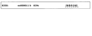
- a “machine language instruction program generation macro call description” is generated.
- the branch destination address is 0x839c and the label statement L_0839c: is inserted before the instruction program description (25th line in FIG. 10) of 0x839c by the program label description generation unit 3a4, the branch is made to this label.
- the program description of FIG. 27 is generated. Even in the case of conditional branching, it can be realized simply by inserting the character string (EQ, NE, etc.) of the corresponding execution condition instead of AL (always: execute unconditionally).
- the “subroutine name character string” of the call destination is searched for the corresponding symbol information from the “symbol information list” based on the call destination address, and the above described “symbol name character string” contained in the symbol information is described above.
- the “subroutine naming rule” is applied to generate the “subroutine name character string”, the program description of FIG. 29 that calls it is generated. Even in the case of a conditional execution subroutine call instruction, it can be realized simply by inserting a character string (EQ, NE, etc.) of the corresponding execution condition instead of AL (always: execute unconditionally).
- Jump table size 6 -Branch destination address table: [0x8384, 0x839c, 0x836c, 0x83a4, 0x836c, 0x8384]
- the execution condition (ls: less or same condition) of this “data dependent branch instruction”
- a program description as shown in FIG. 31 is generated.
- the label of the goto statement that appears after each case statement corresponds to the label of each branch destination address in the “branch destination address table” of the “jump table information”.
- the conditional branch corresponding to case 0: and case 5: corresponds to the default label.
- a data dependent subroutine call instruction in which the call destination address is determined by the register value / memory value
- a data dependent subroutine is used by using “symbol address information” generated by the symbol address information table source generation unit 3b described later. The call is realized on the program description.
- 0x83ac is a “data-dependent branch instruction” that jumps to the value of register r3.
- pc actual value is the current instruction address 0x83a8 + 8
- link register lr immediately before 0x83a8. Since there is an instruction to be assigned to, it can be determined that the instruction at 0x83ac is actually a “data dependent subroutine call instruction”.
- the program description corresponding to the two instructions 0x83a8 and 0x83ac is as shown in FIG.
- FIG. 34 shows an output example of the subroutine program description corresponding to the machine language instruction description of the ARMv5 instruction set of the “jump_test” function in FIG.
- _FP_INFO_ in FIG. 33 is a data structure storing symbol address information defined in advance as shown in FIG.
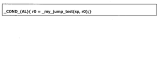
- _GET_FPI _ (_ r_ (3)) in FIG. 33 is the data of the corresponding “symbol address information” from the “symbol address information table” described later, based on the “symbol address” indicated by the value of _r_ (3). This is a function call that returns a pointer to a structure (described later).
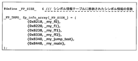
- FIG. 36 shows a program description for enabling the information in the “symbol information list” to be referred to on the program as the initial value setting of the array variable of the aforementioned _FP_INFO_ structure.
- 0x8218 is the initial value of the member variable addr of the _FP_INFO_ structure shown in FIG. 35
- _my_f0 is the initial value of the member variable func.
- _my_f0 is a subroutine name character string having the “prefix character string” “_my_” in the symbol name “f0”, and actually indicates the address value of the target subroutine. In this way, the initial value of the data structure for associating the “symbol address” in the executable binary file with the “subroutine address” in the program description can be set.
- the _GET_FPI_ function shown in FIG. 33 (a function that searches the corresponding _FP_INFO_ structure based on the “symbol address” and returns its pointer) is a simple program as shown in FIG. Can be realized. Also, if the number of symbols included in the symbol address information table is very large, there is a concern that the processing time of the _GET_FPI_ function will be long. In this case, the “binary tree search method”, “hash search method”, etc. And a high-speed search process based on the symbol address may be applied.
- the memory initialization program description generation unit 3c (instruction set simulator program source code output unit 3) generates a program description for initializing the memory area of the CPU in the program description of the instruction set simulator S.
- the initialization target of the memory area may include initial value data in the program area in addition to the data area in which the initial value is defined. Therefore, the program area is also subject to initialization.
- Memory initialization data exists in the binary data part of the execution binary file 5, and information on the positional relationship between each memory area and the “binary data part” is stored in the “segment” included in the “program header table”. They are defined in units or in units of “sections” included in the “section header table”.
- FIG. 38 shows an example of “memory initialization program description”.
- section unit memory initialization processing is described.
- the “.rodata” section with initialization data is defined in the address area of 0x1260c260- 0x127e7, and the specific initialization data is defined as the initialization data of unsignedsignchar data [476]. It is a program description that copies this array data to the address of & arm._mem [0x1260c] by memcpy function.
- FIG. 39 shows a program description example 1 of the highest function of the instruction set simulator.
- FIG. 40 shows a program description example 2 of the top-level function of the instruction set simulator.
- FIG. 41 shows a program description for writing the argument information of the main function to the CPU memory.
- the instruction set simulator program description structure generated as described above has the following characteristics.
- the subroutine in the “execution binary file” directly corresponds to the subroutine on the “program description”, and the “function hierarchy” of the “execution binary file” is the instruction set simulator S. Is directly reflected in the program description output.
- goto statements and label statements clearly correspond to simple branch instructions
- switch statements and case statements correspond to data-dependent branch instructions, making it easy to understand the flow of program control. Therefore, the readability of the program description is high, and code modification work such as program debugging work and program function expansion can be performed efficiently.
- a high-speed instruction set simulation environment By outputting a source program description file (instruction set simulator source code: C language description) having an equivalent function to the execution binary, and compiling and executing it, a high-speed instruction set simulation environment can be constructed as described above.
- a high-speed instruction set simulator having a simulation execution time almost equivalent to the native execution time for example, the time for compiling the program source for the target CPU into machine language and executing it in the CPU
- Equivalent function C description can be output from the execution binary for one target CPU, and the program can be ported to another CPU.
- Malware analysis is possible. Since analysis of the program source is easy, it is possible to easily analyze malware such as viruses, and to contribute to early development of virus removal software and firewalls.
- An instruction set simulator S with a simple tool framework structure that can realize high speed and completeness can be obtained.
- Non-Patent Documents 4, 8, and 9 used for actual use have the following problems to be solved.
- As a first problem there is no information for determining which instruction can be a branch destination address.
- simulation execution time is 14 to 54 times longer than native execution.
- code optimization in the compiler is very difficult.
- As a fourth problem a hierarchical structure is lacking.
- As a fifth problem a program control flow analysis mechanism is lacking as a sixth problem that the readability is extremely low as a source program.
- the branch destination address is added as a label (identification information) to the branch destination instruction, or there is a jump table or the like.
- the instruction set simulator 2S (see FIG. 43) of the second embodiment is obtained by adding a “subroutine argument extraction function” to the instruction set simulator S of the first embodiment. Since the other configuration is the same as that of the instruction set simulator S of the first embodiment, the same components are denoted by the same reference numerals and detailed description thereof is omitted.
- the instruction set simulator 2S of the second embodiment adds a “subroutine argument extraction function” to the instruction set simulator S of the first embodiment, and replaces the CPU registers with local variables and argument variables in the subroutine, thereby This is to further speed up the set simulation.
- FIG. 42 shows a functional block diagram of the machine language instruction analysis unit of the second embodiment.
- Machine language instruction analysis unit 21 of the second embodiment symbol address preprocessing unit 1a of the first embodiment, symbol address acquisition unit 1b, instruction address acquisition unit 1c, next instruction information extraction unit 1d, address list update unit 1e,
- a subroutine argument extraction unit 1f is newly added to the data dependence branch extraction unit 2.
- FIG. 43 shows the configuration of the instruction set simulator 2S of the second embodiment together with the execution binary file 5 to be analyzed and the instruction set simulator program source code 4 output from the instruction set simulator 2S.
- the instruction set simulator 2S of the second embodiment includes a machine language instruction analysis unit 21 and an instruction set simulator program source code output unit 23.
- the instruction set simulator 2S receives the execution binary file 5 and outputs a high-level instruction set simulator program source code 4.
- the instruction set simulator program source code output unit 23 shares subroutine arguments with the subroutine program source generation unit 3a, symbol address information table source generation unit 3b, memory initialization program description generation unit 3c, and main function program description generation unit 3d.
- the processing unit 3e is newly added.
- symbol address information table source generation unit 3b and the subroutine argument common processing unit 3e are used only when the execution binary file 5 of the machine language program includes a data dependent subroutine call instruction.
- Subroutine argument extraction unit 1f The processing by the subroutine argument extraction unit 1f is executed before the instruction address acquisition unit 1c “adds” the “current symbol information” to the “symbol information list” (see FIGS. 42 and 7).
- FIG. 44 shows the information of the “input / output register” of the ARMv5 machine language instruction in FIG.
- the “input / output register” refers to a register (input register) used as an operand by a machine language instruction and a register (output register) whose value is updated by the machine language instruction.
- the targets of the input / output registers include “status register” except for pc (program counter) (since pc has nothing to do with argument extraction processing).
- a plurality of “status registers” are regarded as one register “CC” for convenience, and the register ID is represented as “16”.
- the register ID of sp is expressed as “13”
- the register ID of lr is expressed as “14” as described above.
- Input register ID list (indicated as I (..) in Figure 44): List of register IDs used as operands by machine language instructions
- Output register ID list (indicated as O (..) in Figure 44): List of register IDs used as operands by machine language instructions
- I / O registers A) sub r3, r0, _3: Since the first operand is r0, it becomes I (0), and since the result storage register is r3, it becomes O (3). B) push [lr]: Since the base address is the stack pointer (sp: r [13]) and the write data is the link register (lr: r [14]), it becomes I (13, 14) and the base address register is updated. Therefore, it becomes O (13).
- the “surviving input register ID list” is updated by tracing all “return instructions” in the subroutine in the reverse order of instruction execution.
- the “surviving input register” refers to a register that is referred to in a subroutine after execution of the instruction and that is not updated in the subroutine before the instruction is executed.
- the “surviving input register analysis” process executes the following procedure with each instruction.
- Table 12 shows an analysis example of the input / output register (analysis starts from a 0x8380 return instruction).
- Table 12 shows the “survival input register ID list” when tracing back from the 0x8380 return instruction to the symbol start instruction (0x8340) in the reverse order.
- the “input register ID list” is (0, 13, 14), and it can be seen that the “surviving input register” is r0, sp, lr. The same analysis processing is performed from all other return instructions, so that ⁇ (0, 13, 14) is finally obtained as the “surviving input register ID list”.
- a “subroutine argument” is determined from the “surviving input register ID list” obtained by the above analysis process according to the following rules.
- Stack pointer (sp: r [13]): Considered as “subroutine argument”. Normally, the stack pointer is updated before and after subroutine call processing and subroutine return processing, and is managed by CPU resources. In the second embodiment, all CPU registers including the stack pointer are stored in local variables or subroutine arguments. It is for handling as.
- Instruction information list An instruction information list for analyzing the “surviving input register”. “Instruction information” consists of the following data items. A) Instruction information ID: ID number unique to each instruction information B) Instruction address C) Input register ID list
- next instruction information list the same information as the above “next instruction information temporary list”
- forward instruction information ID list a list (instructions) including instruction information IDs of all instructions that “next instruction” the instruction (Necessary when tracing in reverse order of execution)
- Instruction information ID temporary list A temporary list of instruction information IDs for the reverse execution analysis process of instruction execution.
- FIG. 45 shows a functional block diagram of the subroutine argument extraction unit 1f.
- Subroutine argument extraction unit 1f includes input / output register analysis unit 1f1, forward instruction analysis unit 1f2, subroutine argument extraction preprocessing unit 1f3, instruction information acquisition unit 1f4, survival input register ID list update unit 1f5, and subroutine argument register determination unit 1f6.
- each unit of the subroutine argument extraction unit 1f will be described.
- ⁇ I / O register analysis unit 1f1> The “instruction address” is sequentially obtained one by one from the “instruction address list” of the “current symbol information”, and “instruction information” corresponding to the instruction address is generated. Then, set the “instruction information ID” in the “instruction information” as appropriate (so as not to overlap), set the “instruction address” of the instruction, and enter the “input register ID list”, “output register ID list”, “next” Create an instruction information list. The next instruction information extraction unit 1d is used to create the “next instruction information list”. At this time, the “surviving input register ID list” and “forward instruction information ID list” of each “instruction information” are set to “empty”. After the process for all “instruction addresses” is completed, the process proceeds to the process of the forward instruction analysis unit 1f2.
- ⁇ Forward command analysis unit 1f2> In each “instruction information” in the “instruction information list” (hereinafter, “instruction information” is referred to as “current instruction information”), “immediate type next instruction” and “branch” included in the “next instruction information list” Based on each “next instruction address” of “type next instruction”, the corresponding “instruction information” is searched. Search for an instruction whose instruction address matches the next instruction address. The “command information” searched for hereinafter is referred to as “next command information”. “Instruction information ID” of “current instruction information” is “added” (non-overlappingly) to “forward instruction information ID list” of “next instruction information”. After the processing for all “instruction information” is completed, the process proceeds to the subroutine argument extraction preprocessing unit 1f3.
- ⁇ Instruction information acquisition unit 1f4> The “command information ID” is “taken out” from the “command information ID temporary list”, the corresponding “command information” is acquired, and the process proceeds to the survival input register ID list update unit 1f5. Hereinafter, this is referred to as “current command information”. When the “command information ID temporary list” is “empty”, the process proceeds to the subroutine argument register determination unit 1f6.
- ⁇ Surviving input register ID list update unit 1f5> The following process is executed, and the process returns to the process of the instruction information acquisition unit 1f4. (1) If each “output register ID” in the “output register ID list” of “current instruction information” is included in the “subroutine survival input register ID temporary list”, the register ID is set to “subroutine survival input register ID temporary”. Delete from list. (2) “Add” (non-overlappingly) each “input register ID” in the “input register ID list” of the “current instruction information” to the “subroutine survival input register ID temporary list”.
- the subroutine argument sharing processing unit 3e executes the process of the subroutine argument extraction unit 1f after executing all the “symbol information” included in the “symbol information list” (see FIG. 42). This processing is necessary only when the “symbol information list” includes “symbol information” whose “data dependent subroutine call instruction flag” is “1”. The reason why this processing is necessary is that, when a data-dependent subroutine is realized by a program description, a “common” function pointer data type (the number of arguments is also shared) is required for all subroutines.
- CPU resource reference macro definition The CPU resource reference macro definition in FIG. 14 is based on the premise that the CPU register variable is defined in the CPU resource data structure (see FIG. 13). The CPU register variable is defined as a subroutine argument variable or a local variable. Therefore, the CPU resource reference macro is changed as shown in FIG.
- Subroutine definition description generator In the second embodiment, the function type of the subroutine is different from that in the first embodiment.
- the data type of each argument is the same as the data type of the CPU register as well as the “return value”.
- the argument name is generated based on the register number and the register alias name (such as the alias name sp of r [13]).
- FIG. 47 shows the subroutine definition description output of the “jump_test” function.
- FIG. 48 shows a subroutine definition description example of the second embodiment. Here, it is assumed that the number of subroutine arguments does not change even after execution of “subroutine argument sharing processing unit 3e”.
- Subroutine return value A description for storing the subroutine return value in a register variable is generated. (Even if there is no actual subroutine return value, there is no inconvenience in program execution)
- FIG. 50 shows a subroutine call program description of the second embodiment.
- FIG. 50 shows a data dependent subroutine call instruction program description of the second embodiment. As described above, it is assumed that the “common subroutine argument register ID list” is the same as the “subroutine argument register ID list” of the subroutine “my_jump_test”.
- FIG. 51 shows a software development environment for an embedded system using the instruction set simulator of the third embodiment.
- the instruction set simulator 3S of the third embodiment includes a machine language instruction analysis unit 31 when there is no symbol table in the first embodiment and the second embodiment.
- the execution binary file includes a “symbol table”.
- a third embodiment for dealing with a case where a “symbol table” does not exist will be described.
- the machine language instruction analysis unit 1 (21) and the instruction set simulator program source code output unit 3 of the first and second embodiments include a machine language instruction analysis unit 31, an instruction set simulator program source code output Changed to part 33.
- the machine language instruction analyzing unit 31 has an unanalyzed symbol address detecting unit 31a.
- the only information specifying the position of the machine language instruction is the “entry point” (the instruction address executed first after the program is started). Therefore, first, the unanalyzed symbol address detector 31a adds only the “entry point” to the “symbol address temporary list”.
- the machine language instruction analyzing unit 31 has a symbol candidate address list 31a1.
- the “symbol candidate address list” is an address list of “symbol candidates”.
- the initial state of the symbol candidate address list 31a1 is “empty”, and when an “unanalyzed” symbol address is found, the unanalyzed symbol address detector 31a adds it to the symbol candidate address (described later).
- Each address of the “symbol candidate address list” is added to the “symbol address temporary list”.
- the instruction set simulator 3S can cope with a case where there is no symbol table in the execution binary file.
- the same operational effects as in the first embodiment can be obtained, the detailed operation can be reproduced, and the processing speed of the simulator is fast.
- the C language is exemplified as the high-level programming language that is reverse-compiled from the execution binary.
- the high-level programming language other than the C language can of course be substituted for the language to be reverse-compiled.
- the program source code in the claims refers to C language or the like converted from machine language by the instruction set simulator S, 2S, 3S described in the embodiment, and the program source code may be a programming language other than C language. Of course it is good.
- 1c Instruction address acquisition unit (subroutine detection means, subroutine call instruction detection means) 1d Next instruction information extraction unit (subroutine detection means, subroutine call instruction detection means, branch instruction detection means, simple branch instruction detection means, simple subroutine call instruction detection means, data dependent branch instruction detection means, data dependent subroutine call instruction detection means) 1e Address list update unit (subroutine detection means, simple subroutine call instruction detection means, data dependent subroutine call instruction detection means) 1f Subroutine argument extraction unit (subroutine detection means, register variable expansion means) 2 Data dependent branch information extraction unit (subroutine detection means, branch instruction detection means, data dependent branch instruction detection means, data dependent subroutine call instruction detection means, branch destination address information reading section) 2f (Subroutine machine language address table generation means) 2g Jump table information generation unit (jump table recording means, subroutine machine language address table generation means) 3 Instruction set simulator program source code output section (data dependent branch instruction generation means) 3a Subroutine program source generator (subroutine source code output means, subroutine call instruction output means)
Landscapes
- Engineering & Computer Science (AREA)
- General Engineering & Computer Science (AREA)
- Theoretical Computer Science (AREA)
- Software Systems (AREA)
- Physics & Mathematics (AREA)
- General Physics & Mathematics (AREA)
- Computing Systems (AREA)
- Debugging And Monitoring (AREA)
Abstract
本発明の命令セットシミュレータ(S)は、サブルーチン検出手段(1d、1e、1f、2)と、分岐命令検出手段(1d、2)と、サブルーチン呼出し命令検出手段(1c、1d)と、サブルーチンソースコード出力手段(3a、3e)と、識別子付加手段(3a4)と、無条件分岐命令出力手段(3a5、3a6、3a8)と、サブルーチン呼出し命令出力手段(3a8、3a9)とを備える。
Description
本発明は、機械語からプログラムソースコードに変換したり、プログラムソースコードから機械語に変換することで生成される命令セットシミュレータおよびそのシミュレータ生成方法に関する。
従来、本発明に係る技術に関連する既存技術として逆コンパイラと命令セットシミュレータがある。
逆コンパイラとは、コンピュータが直接実行する実行バイナリ(機械語)からプログラマ等が作成するプログラムソースコードに変換する技術である。つまり、逆コンパイラとは、プログラムソースコードから実行バイナリに変換するコンパイラの逆変換を行うものである。
逆コンパイラとは、コンピュータが直接実行する実行バイナリ(機械語)からプログラマ等が作成するプログラムソースコードに変換する技術である。つまり、逆コンパイラとは、プログラムソースコードから実行バイナリに変換するコンパイラの逆変換を行うものである。
逆コンパイラ技術の開発は、1960年代から始まり、当初は、あるプラットフォーム用のプログラムを別のプラットフォームに移植する作業の補助として使用されていた。その後、逆コンパイラ技術は、誤って失われたソースコードの復元の補助、プログラムのデバッグ、ウィルスプログラムの発見・解析、プログラム内容の解析・理解、プログラム全体の高位処理構造の抽出等に応用されている。
一方、命令セットシミュレータは、プロセッサの動作を模擬して実行バイナリを実行するツールであり、逆コンパイラ技術が目的とする「可読性の高いソースプログラム復元」と異なる目的を持つ。命令セットシミュレータには、下記の翻訳方式、静的コンパイル方式、動的コンパイル方式の3種類の方式がある。
以下、3種類の命令セットシミュレータ方式を説明する。なお、以下で「ホストCPU」とは、命令セットシミュレータを実行するCPUを指す。
翻訳(Interpreter)方式(非特許文献3):実行バイナリから機械語命令を一つずつデコード(解釈)しながらCPU動作を模擬する。デコード処理がオーバーヘッドとなりシミュレーション速度が遅い。
翻訳(Interpreter)方式(非特許文献3):実行バイナリから機械語命令を一つずつデコード(解釈)しながらCPU動作を模擬する。デコード処理がオーバーヘッドとなりシミュレーション速度が遅い。
静的コンパイル(Static compile)方式(非特許文献4、5、8、9、10):実行バイナリすべてをまとめてデコードし、ホストCPUの機械語命令に変換した後に実行する。また、ホストCPUの機械語命令に変換する過程で、C言語等のソースコードに変換する場合もある。
動的コンパイル(Dynamic compile)方式(非特許文献6、7):翻訳方式の改良として、一度デコードしたホストCPUの機械語命令系列をメモリに保存してこれを実行することにより、同じ命令を実行するたびに毎回デコードするオーバーヘッドを軽減する。この方式は、ターゲットCPU命令セットからホストCPU命令セットへの変換を行うバイナリ変換(Binary translation)のため、命令セット変換機構をすべて実装する必要があり、ツール実装は非常に複雑になる。
Michael Van Emmerik, "Static Single Assignment for Decompilation", PhD Thesis, The University of Queensland, (2007 http://www.backerstreet.com/decompiler/vanEmmerik_ssa.pdf)
http://www.program-transformation.org/Transform/DeCompilation
D. Burger, T. M. Austin, "The simplescalar tool set, version 2.0", Computer Architecture News, pp.13-25, 1997
C. Mills, S. Ahalt, J. Fowler, "Compiled instruction set simulation", Software - Practice and Exprerience, 21(8), pp.877 - 889, 1991
Jianwen Zhu, and Daniel D. Gajski, "An Ultra-Fast Instruction Set Simulator", IEEE Trans. VLSI Systems, Vol.10, No.3, pp.363 - 373, 2002
A. Nohl, G. Braun, O/ Schliebusch, R. Leupers, H. Meyr, A. Hoffmann, "A universal technique for fast and flexible instruction-set architecture simulation", Proceedings of DATE 2002
M. Reshadi, P. Mishra, N. Dutt, "Instruction Set Compiled Simulation: A Technique for Fast and Flexible Instruction Set Simulation", Proceeding of DAC 2003, pp. 758 ‐ 763, 2003
M. Bartholomeu, R. Azevedo, S. Rigo, G. Araujo, "Optimizations for compiled simulation using instruction type information", Proceedings of the 16th Symposium on Computer Architecture and High Performance Computing (SBAC-PAD'04), pp.74 ‐ 81, 2004
Joseph D'Errico, Wei Qin, "Constructing Portable Compiled Instruction-set Simulators ‐ An ADL-driven Approach", Proceeding of DATE 2006, pp.112 ‐ 117, 2006
S. Bansal, A, Aiken, "Binary translation using peephole superoptimizers", Proceedings of OSDI'08, pp.177 - 192, 2008
Wikipedia: Instruction Set Simulator http://ja.wikipedia.org/wiki/命令セットシミュレータ http://en.wikipedia.org/wiki/Instruction_set_simulator
Wikipedia: Binary Translation http://en.wikipedia.org/wiki/Binary_translation
ところで、上述の既存の逆コンパイラの課題として、以下の技術的課題がある(非特許文献1のP15~P28参照)。
第1に、データ型の復元が困難である。つまり、実行バイナリから元のソースコードのデータ型を推定することが技術的に非常に難しい。
第1に、データ型の復元が困難である。つまり、実行バイナリから元のソースコードのデータ型を推定することが技術的に非常に難しい。
第2に、「間接分岐」のプログラム制御フローの解析が困難である。具体的には、レジスタ値をPC(プログラムカウンタ)に代入する命令は、C言語でのswitch文(分岐命令)、case文のコード実装で見られる他、関数ポインタを使った関数呼出しでも、レジスタ値をPCに代入する。このようにプログラム制御フローがデータ依存(レジスタの値でプログラム実行遷移が変わる)となる場合の解析が非常に難しい。
第3に、関数引数・戻り値の復元が困難である。つまり、関数の引数形式や戻り値形式は、ターゲットプロセッサの命令セットに依存するだけでなく、Calling Convention(関数呼出しにおける引数形式や戻り値形式の取り決め)に依存する。そのため、このような予備情報無しに関数の引数や戻り値を復元することが難しい。
第4に、完全性という点で逆コンパイラによって出力されたソースコードは以下の2つの課題がある。なお、非特許文献1のP26~P27では、2002年当時で何らかの成果を挙げているのは、dcc decompilerとREC(Reverse Engineering Compiler)のたった2つだけである、としている。
一つ目の課題として、手動編集の必要性(REC)がある。多くの既存の逆コンパイラは手動編集なしにコンパイル可能形式にすることが出来ない。具体的には、出力ソースコードの可読性に重きをおいているため、コンパイル可能形式を保証する逆コンパイラは非常に少ない。
二つ目の課題として、プログラム複雑度の限界(dcc)がある。具体的には、生成ソースコードのコンパイル可能形式を保証する場合でも、プログラム複雑度の制限により扱えるプログラムが限定される。
非特許文献1の手法と解決した課題として、逆コンパイラの中間言語にSSA(static single assignment)形式を採用し、高度なデータ依存性解析を行うことで可読性の高いソース出力を行っている。その他、複数の個別の機械語命令を連結した「式」(expression)を可読性の高い表記形式でソースコードに出力できる、関数引数・戻り値の正確な抽出、変数・関数引数・戻り値のデータ型の高精度な推測、間接分岐のプログラム制御フローの正確な解析が挙げられる。
ただし、「手動編集の必要性」を排除または削減する効果についての言及は特になく、逆コンパイラの完全性に関する効果は限定的であると考えられる。
ただし、「手動編集の必要性」を排除または削減する効果についての言及は特になく、逆コンパイラの完全性に関する効果は限定的であると考えられる。
そこで、逆コンパイラの完成度を上げるための技術構築が望まれる。前記した技術課題(一部は非特許文献1で解決)を克服するためには、 コンパイラ環境と同程度の技術構築が必要となり、非常に複雑な処理工程が数多く必要となる。一方、コンパイラは逆コンパイラと比べて圧倒的に需要が大きく、その開発リソース(コンパイラ開発に従事する研究者・技術者、技術フォーラム等)も圧倒的に多い。そのため、逆コンパイラの技術成熟度はコンパイラ技術に比べかなり劣ることが大きな課題である。
一方、前記した命令セットシミュレータは、逆コンパイラ技術の課題である「完全性」(どのようなプログラムでも確実にシミュレーション可能であるということ)については満足できている。
通常は、静的コンパイル方式が実行バイナリすべてをまとめてデコードすることから、最も高速なシミュレーションが可能とされている。しかし、機械語命令のデコード結果をCソースコードに変換する方式の場合(非特許文献4、8、9)、元のプログラムを直接ホストCPUで実行する(ネイティブ実行)と比べ、14倍~54倍のシミュレーション時間がかかるというデータが非特許文献8で報告されている。
通常は、静的コンパイル方式が実行バイナリすべてをまとめてデコードすることから、最も高速なシミュレーションが可能とされている。しかし、機械語命令のデコード結果をCソースコードに変換する方式の場合(非特許文献4、8、9)、元のプログラムを直接ホストCPUで実行する(ネイティブ実行)と比べ、14倍~54倍のシミュレーション時間がかかるというデータが非特許文献8で報告されている。
これに対して、非特許文献5、10では、変換結果を直接ホストCPUの機械語命令として出力することで、様々なコード最適化が可能となり、ネイティブ実行時間とほぼ匹敵するシミュレーション時間が実現できるとしている。一方、実行バイナリと等価動作をするソースプログラムの生成を行うことができる方式は、静的コンパイル方式の中でもホストCPUの機械語命令に変換する前にソースプログラムを出力する方式(非特許文献4、8、9)だけである。
なお、非特許文献5、10では、変換結果を直接ホストCPUの機械語命令として出力する方式は、一のプラットフォームを他のプラットフォームに移植できない、変換対象のプログラムの解析ができない、ウイルスの発見、解読、解析ができない等の難点がある。
そのため、実際の使用に供されるのは、機械語命令のデコード結果をCソースコードに変換する方式(非特許文献4、8、9)のみである。
そのため、実際の使用に供されるのは、機械語命令のデコード結果をCソースコードに変換する方式(非特許文献4、8、9)のみである。
しかし、機械語命令のデコード結果をCソースコードに変換する方式(非特許文献4、8、9)は、前記したように、シミュレーション時間がネイティブ実行と比べ、14倍~54倍かかり、シミュレーション時間が長いという問題がある。
また、非特許文献4、8、9の方式は、後記するように、変換したCソースコードの解析が困難であるという問題がある。そのため、ウイルスの発見、解読、解析が困難である。
また、非特許文献4、8、9の方式は、後記するように、変換したCソースコードの解析が困難であるという問題がある。そのため、ウイルスの発見、解読、解析が困難である。
ここで、本発明の構成を明らかにするために、本発明に最もアプローチが類似している非特許文献4、8、9が有する課題(本発明が解決すべき課題)について、Cコード出力形式を示して具体的に説明する。
非特許文献4、8、9は、前記のStatic compile方式命令セットシミュレータの中で、実行バイナリの変換結果をC言語等の高級プログラミング言語による記述で出力する技術である。これらのCコード出力のアプローチは、最初の非特許文献4で提案された方式を後続の非特許文献8、9でも採用している。
図53、図54に、非特許文献4で説明されているCコード出力形式を示す。図53は、非特許文献4の機械語命令用Cマクロ定義であり、図54は、非特許文献4の実行バイナリと等価動作するCコード出力である。
図54の4行目の「register UL * S = M, *F = H, A = 0, P = START;」は、以下を意味する。
図54の4行目の「register UL * S = M, *F = H, A = 0, P = START;」は、以下を意味する。
Sはスタックポインタ、Fはフレームポインタ、Aはアキュムレータ、PはPC(プログラムカウンタ)にそれぞれ対応した関数内部のローカル変数であり、4つのレジスタだけを持つ極めて単純なCPUモデルである。execute関数からリターンする(図54の下から3行目)ときは、SAVESTATEマクロ(図54の下から4行目)によって、これらCPUレジスタ値をグローバル変数に保存する。
図54の6行目以降の「for(;;) switch(P)[ … ]」は、以下を意味する。
命令セットシミュレーションのメインループであり、HALT命令(cpu停止命令)かdefaultラベル(未定義命令アドレスに分岐、エラー処理)に到達するまで実行を繰返す。
switch(P)は、機械語命令アドレスに対応する各case文(Cマクロ内部に埋込まれている)に分岐する構造を持っている。
命令セットシミュレーションのメインループであり、HALT命令(cpu停止命令)かdefaultラベル(未定義命令アドレスに分岐、エラー処理)に到達するまで実行を繰返す。
switch(P)は、機械語命令アドレスに対応する各case文(Cマクロ内部に埋込まれている)に分岐する構造を持っている。
各機械語命令用Cマクロは、アドレス値をcaseラベルとして持ち、そのアドレスの機械語命令動作のC記述を含む。
分岐命令(CBLS:条件分岐,JSR:サブルーチン呼出し,UNLK:リターン)のCマクロには、プログラムカウンタの更新処理とbreak文を含んでおり、その機械語命令処理の後、switch文に制御が戻り、次命令アドレスに分岐する構造である。
分岐命令(CBLS:条件分岐,JSR:サブルーチン呼出し,UNLK:リターン)のCマクロには、プログラムカウンタの更新処理とbreak文を含んでおり、その機械語命令処理の後、switch文に制御が戻り、次命令アドレスに分岐する構造である。
一つのswitch文に含まれるcase文の数には上限があるため、大きなプログラムに対応するためには、プログラムを分割して複数のswitch文を使用して実現する必要がある。(後記の非特許文献8でもプログラム分割を行っている)
図55A、図55Bには、非特許文献4の手法を引用した非特許文献8におけるCコード構造を示す。
図55Aの1行目の「Region3()」は、特定アドレス範囲の機械語命令の実行動作の記述である。以下、各命令を説明する。
図55Aの3行目の「switch文」は、PC(プログラムカウンタ:図中ac_pc)の値によって、該当する命令アドレスのcase文に分岐する。
図55Aの1行目の「Region3()」は、特定アドレス範囲の機械語命令の実行動作の記述である。以下、各命令を説明する。
図55Aの3行目の「switch文」は、PC(プログラムカウンタ:図中ac_pc)の値によって、該当する命令アドレスのcase文に分岐する。
図55Aの5、11行目の「case文」は、caseのラベル値が命令アドレスに対応しており、そのアドレスの命令の動作がCコードで記述されている。次命令へのプログラム制御(PCの更新)も行い、末尾の各break文によってswitch文に戻る。
図55Aの18行目の「default文」は、Region3()の範囲外の命令アドレスの場合は関数を終了する。
図55Bの1行目の「Execute()」は、シミュレータのメイン関数で、プログラムカウンタの上位ビットによって、該当するプログラム領域に対応するRegionXX()関数を呼ぶ。
図55Aの18行目の「default文」は、Region3()の範囲外の命令アドレスの場合は関数を終了する。
図55Bの1行目の「Execute()」は、シミュレータのメイン関数で、プログラムカウンタの上位ビットによって、該当するプログラム領域に対応するRegionXX()関数を呼ぶ。
非特許文献8のCコードの最適化手法(非特許文献8の5. Optimization Techniques参照)は、以下2つの最適化手法を適用してCコード記述に反映させる。なお、これらの最適化手法は、非特許文献4で示されたCコードでは既に実現されている。
Optimization 1(最適化1):PCが不連続な変化(分岐,コール等)をしない通常の命令では、次命令は直後のcase文になるので、無駄なbreak文を削除する。
Optimization 2(最適化2):PCが不連続な変化(分岐,コール等)をするときのみ、PCの更新を行う。
Optimization 1(最適化1):PCが不連続な変化(分岐,コール等)をしない通常の命令では、次命令は直後のcase文になるので、無駄なbreak文を削除する。
Optimization 2(最適化2):PCが不連続な変化(分岐,コール等)をするときのみ、PCの更新を行う。
上述の非特許文献8の命令セットシミュレータは、当時の既存技術よりも最も速いとしており、それでもネイティブ実行と比べ14倍~54倍のシミュレーション実行時間がかかると報告されている。
以下に、上記非特許文献4、8、9の手法で得られる命令セットシミュレータのCコード(以降「命令セットシミュレータソースコード」と呼ぶ)に関する課題を説明する。
以下に、上記非特許文献4、8、9の手法で得られる命令セットシミュレータのCコード(以降「命令セットシミュレータソースコード」と呼ぶ)に関する課題を説明する。
第1の課題として、各命令アドレスに対応したcase文が必要となる理由(非特許文献7:3ページ目、右欄第1パラグラフ:Each instruction of the decoded application corresponds to respective behavior function call in the generated simulator. These functions must be accessed randomly, as all of them can be a potential target of a jump instruction. ... The switch is based on the Program Counter.)として、実行バイナリは、アセンブリプログラムと異なり、分岐先命令ラベルの情報が欠如している。従って、どの命令が分岐先アドレスとなり得るかを判断する情報がない。このため、「すべての」命令が分岐先アドレスとなり得る、という前提に基づき、switch文から各case文の命令動作コードに直接実行が遷移できるような構造が必要となる。
第2の課題として、シミュレーション実行時間がネイティブ実行に比べ14倍~54倍かかるため、命令セットシミュレータソースコードを別CPUへポーティングする目的で使うことは大きなオーバーヘッドを伴うため実用的でない。シミュレーション実行時間が大きくなる要因は、PCに関するswitch文と各機械語命令のアドレスに対応するcase文の構造から来ている。
第3の課題として、最適化の問題がある。
switch文から任意のcase文へ分岐するコード構造では、分岐先情報が欠如していることからcompilerにおけるコード最適化が非常に掛かりにくくなる。 特に、ここで重要となるコード最適化は、後に使用されない命令を除去する「デッドコード除去」(dead code elimination)であり、シミュレーション実行時間に大きく影響を与える。命令セットシミュレータの動作記述では、 PCや状態フラグ(ゼロフラグ,符号フラグ,オーバーフローフラグ)が最も頻繁に更新され、これらの更新処理の記述が全体の動作記述の大きな部分を占めており、これらが最適化されないため、ネイティブ実行に比べて大きな処理オーバーヘッドとなる原因となっている。
switch文から任意のcase文へ分岐するコード構造では、分岐先情報が欠如していることからcompilerにおけるコード最適化が非常に掛かりにくくなる。 特に、ここで重要となるコード最適化は、後に使用されない命令を除去する「デッドコード除去」(dead code elimination)であり、シミュレーション実行時間に大きく影響を与える。命令セットシミュレータの動作記述では、 PCや状態フラグ(ゼロフラグ,符号フラグ,オーバーフローフラグ)が最も頻繁に更新され、これらの更新処理の記述が全体の動作記述の大きな部分を占めており、これらが最適化されないため、ネイティブ実行に比べて大きな処理オーバーヘッドとなる原因となっている。
第4の課題として、階層構造の欠如の問題がある。
分岐命令では、PC更新処理の後、break文によってプログラム制御がswitch文に戻った後にcase文に分岐する一連の処理も、ジャンプテーブル(メモリ)へのアクセスが発生するため、この部分も処理オーバーヘッドの原因となる。つまり、実行バイナリの関数階層構造が出力Cソースコードに反映されていないため、処理が長く時間がかかる原因となっている。
分岐命令では、PC更新処理の後、break文によってプログラム制御がswitch文に戻った後にcase文に分岐する一連の処理も、ジャンプテーブル(メモリ)へのアクセスが発生するため、この部分も処理オーバーヘッドの原因となる。つまり、実行バイナリの関数階層構造が出力Cソースコードに反映されていないため、処理が長く時間がかかる原因となっている。
第5の課題として、可読性が低いという問題がある。
また、switch文に含むcase文の数の上限からプログラムを機械的に分割したCコード構造は、ソースプログラムとしては著しく可読性が低い。そのため、プログラムのプログラムのエラーを修正するデバッグ作業や、プログラムの機能拡張などのコード改変作業などが著しく困難になっている。
また、switch文に含むcase文の数の上限からプログラムを機械的に分割したCコード構造は、ソースプログラムとしては著しく可読性が低い。そのため、プログラムのプログラムのエラーを修正するデバッグ作業や、プログラムの機能拡張などのコード改変作業などが著しく困難になっている。
第6の課題として、プログラム制御フロー解析の欠如という問題がある。
命令セットシミュレーション技術は、プロセッサのシミュレーション機能を実装する部分に対して焦点が当てられ、コンパイラ・逆コンパイラ技術と十分な連携を取らないまま発展してきた経緯がある。そのため、コンパイラ技術のプログラム制御フロー解析の仕組みを取り入れた命令セットシミュレータは存在しない。
命令セットシミュレーション技術は、プロセッサのシミュレーション機能を実装する部分に対して焦点が当てられ、コンパイラ・逆コンパイラ技術と十分な連携を取らないまま発展してきた経緯がある。そのため、コンパイラ技術のプログラム制御フロー解析の仕組みを取り入れた命令セットシミュレータは存在しない。
図56、図57に、従来の組込みシステム用ソフトウエア開発環境のプログラムを示し、各ケースのメリット、デメリットについて説明する。
図56に、従来の命令セットシミュレータを用いない組込みシステム用ソフトウエア開発環境を示す。
図56に、従来の命令セットシミュレータを用いない組込みシステム用ソフトウエア開発環境を示す。
従来、命令セットシミュレータを用いない組込みシステム用ソフトウエア開発環境は、ターゲットCPU搭載組み込みシステム製品(実機)の場合と、ホストCPU搭載コンピュータの場合とがある。
ソフトウエア開発環境がターゲットCPU搭載組み込みシステム製品(実機)の場合、ターゲットCPU用のプログラムソースコードまたはアセンブリコードは、ターゲットCPU用コンパイラで機械語の実行バイナリファイルに変換される。実行バイナリファイルは、ターゲットCPU搭載組み込みシステム製品のメモリに格納される。
ソフトウエア開発環境がターゲットCPU搭載組み込みシステム製品(実機)の場合、ターゲットCPU用のプログラムソースコードまたはアセンブリコードは、ターゲットCPU用コンパイラで機械語の実行バイナリファイルに変換される。実行バイナリファイルは、ターゲットCPU搭載組み込みシステム製品のメモリに格納される。
このケースでは、開発されたプログラムソースコードまたはアセンブリコードが最終製品のターゲットCPU搭載組み込みシステム製品(実機)に組み込まれるので、詳細な動作が可能である。しかし、実機であるので、各種条件のテストケースを設定するのが困難であり、エラー修正のためのデバッグ作業が困難である。
一方、ソフトウエア開発環境がホストCPU搭載コンピュータの場合、ターゲットCPU用のプログラムソースコードまたはアセンブリコードは、ホストCPU用コンパイラで機械語の実行バイナリファイルに変換される。実行バイナリファイルは、ホストCPU搭載コンピュータに格納される。
このケースでは、開発されたプログラムソースコードまたはアセンブリコードがホストCPU搭載コンピュータに組み込まれ実機ではないので、詳細な動作の再現が無理となる。しかし、ホストCPU搭載コンピュータであるので、各種条件のテストケースを設定することが可能で、エラー修正のためのデバッグ作業が容易である。
図57に、従来の命令セットシミュレータを用いた組込みシステム用ソフトウエア開発環境を示す。
ターゲットCPU用のプログラムソースコードまたはアセンブリコードは、ターゲットCPU用コンパイラで機械語の実行バイナリファイルに変換される。実行バイナリファイルは、命令セットシミュレータで、ホストCPU用の実行バイナリファイルに変換される。ホストCPU用の実行バイナリファイルは、ホストCPU搭載コンピュータで実行される。ターゲットCPU用の実行バイナリファイルから命令セットシミュレータで、ホストCPU用の実行バイナリファイルに変換されるので、ホストCPU搭載コンピュータでの詳細動作の再現が可能である。
ターゲットCPU用のプログラムソースコードまたはアセンブリコードは、ターゲットCPU用コンパイラで機械語の実行バイナリファイルに変換される。実行バイナリファイルは、命令セットシミュレータで、ホストCPU用の実行バイナリファイルに変換される。ホストCPU用の実行バイナリファイルは、ホストCPU搭載コンピュータで実行される。ターゲットCPU用の実行バイナリファイルから命令セットシミュレータで、ホストCPU用の実行バイナリファイルに変換されるので、ホストCPU搭載コンピュータでの詳細動作の再現が可能である。
ターゲットCPU用の実行バイナリファイルがホストCPU用の実行バイナリファイルに変換されるので機械語の文法が異なり、シミュレーション時間が長い。
以上のことから、従来技術の解決すべき課題をまとめると、従来技術として、プログラムソースコードを機械語に変換する逆コンパイラ技術と、プロセッサの動作を模擬して実行バイナリを実行する命令セットシミュレータとがある。
逆コンパイラ技術は以下の課題がある。
第1に、データ型の復元が困難である。
第2に、「間接分岐」のプログラム制御フローの解析が困難である。
第3に、関数引数・戻り値の復元が困難である。
第4に、完全性という点で逆コンパイラによって出力されたソースコードは以下の2つの課題がある。一つ目の課題として、多くの既存の逆コンパイラは手動編集なしにコンパイル可能形式にすることが出来ない。二つ目の課題として、プログラム複雑度の制限により扱えるプログラムが限定される。
第1に、データ型の復元が困難である。
第2に、「間接分岐」のプログラム制御フローの解析が困難である。
第3に、関数引数・戻り値の復元が困難である。
第4に、完全性という点で逆コンパイラによって出力されたソースコードは以下の2つの課題がある。一つ目の課題として、多くの既存の逆コンパイラは手動編集なしにコンパイル可能形式にすることが出来ない。二つ目の課題として、プログラム複雑度の制限により扱えるプログラムが限定される。
非特許文献1は、可読性の高いソース出力で上記第1のデータ型の復元が困難な問題を解決し、第2の「間接分岐」のプログラム制御フローの解析が困難、第3の関数引数・戻り値の復元が困難等の問題を解決している。しかし、第4の完全性の問題は未解決である。
一方、命令セットシミュレータでは、逆コンパイラ技術で未解決な第4の完全性については満足できている。しかし、命令セットシミュレータは、元のプログラムを直接ホストCPUで実行する(ネイティブ実行)と比べ、14倍~54倍のシミュレーション時間がかかるという問題がある。
ターゲットCPUの機械語命令を直接ホストCPUの機械語命令として出力する非特許文献5、10では、ネイティブ実行時間とほぼ匹敵するシミュレーション時間が実現できる。しかし、機械語命令を他の機械語命令として出力する非特許文献5、10では、一のプラットフォームを他のプラットフォームに移植できない、変換対象のプログムの解析ができない、ウイルスの発見、解読、解析ができない等の問題がある。
そのため、結果的に実際の使用に供されるのは、非特許文献5、10の問題である一のプラットフォームを他のプラットフォームに移植できない、変換対象のプログムの解析ができない、ウイルスの発見、解読、解析ができない等を解消できる、機械語命令のデコード結果をCソースコードに変換する方式(非特許文献4、8、9)のみである。
しかし、前述したように、非特許文献4、8、9の命令セットシミュレータでは、次の解決すべき課題がある。
しかし、前述したように、非特許文献4、8、9の命令セットシミュレータでは、次の解決すべき課題がある。
第1の課題として、どの命令が分岐先アドレスとなり得るかを判断する情報がない。
第2の課題として、シミュレーション実行時間がネイティブ実行に比べ14倍~54倍かかる。
第3の課題として、compilerにおけるコード最適化が非常に掛かりにくい。
第2の課題として、シミュレーション実行時間がネイティブ実行に比べ14倍~54倍かかる。
第3の課題として、compilerにおけるコード最適化が非常に掛かりにくい。
第4の課題として、階層構造が欠如している。
第5の課題として、復元されるソースプログラムがサブルーチンの構造さえ実現していないので、ソースプログラムとしては著しく可読性が低い。
第6の課題として、プログラム制御フロー解析の仕組みが欠如している。
そこで、本願は実際の使用に供される非特許文献4、8、9の上述の第1~第6の課題を解決するものである。
第5の課題として、復元されるソースプログラムがサブルーチンの構造さえ実現していないので、ソースプログラムとしては著しく可読性が低い。
第6の課題として、プログラム制御フロー解析の仕組みが欠如している。
そこで、本願は実際の使用に供される非特許文献4、8、9の上述の第1~第6の課題を解決するものである。
本発明は上記実状に鑑み創案されたものであり、実行バイナリからソースプログラム記述ファイル(命令セットシミュレータソースコード:C言語記述)の復元を確実に行え、解析が容易なソースプログラム記述ファイルを出力でき、高速な命令セットシミュレーション環境を構築できる命令セットシミュレータおよびそのシミュレータ生成方法の提供を目的とする。
前記課題を解決するため、従来考慮されていなかった以下に詳述する新しい8つの処理技術を導入した。
第1の本発明の命令セットシミュレータは、機械語プログラムをプログラムソースコードに変換して生成される命令セットシミュレータであって、前記機械語プログラムに含まれるサブルーチンを検出するサブルーチン検出手段と、前記機械語プログラムに含まれる命令語のうち分岐先アドレスを有する分岐命令を検出する分岐命令検出手段と、前記機械語プログラムに含まれる命令語のうちサブルーチン呼出し先アドレスを有するサブルーチン呼出し命令を検出するサブルーチン呼出し命令検出手段と、前記機械語プログラムを前記サブルーチン検出手段で検出した各サブルーチン単位のプログラムソースコードを出力するサブルーチンソースコード出力手段と、前記分岐先アドレスを示す識別子を前記プログラムソースコードの分岐先の命令に付加する識別子付加手段と、前記機械語プログラムの前記分岐命令を、前記プログラムソースコードの前記識別子をもつ命令への無条件分岐命令にして出力する無条件分岐命令出力手段と、前記機械語プログラムのサブルーチン呼出し命令を、前記プログラムソースコードのサブルーチン呼出し命令にして出力するサブルーチン呼出し命令出力手段とを備えている。
第1の本発明の命令セットシミュレータは、機械語プログラムをプログラムソースコードに変換して生成される命令セットシミュレータであって、前記機械語プログラムに含まれるサブルーチンを検出するサブルーチン検出手段と、前記機械語プログラムに含まれる命令語のうち分岐先アドレスを有する分岐命令を検出する分岐命令検出手段と、前記機械語プログラムに含まれる命令語のうちサブルーチン呼出し先アドレスを有するサブルーチン呼出し命令を検出するサブルーチン呼出し命令検出手段と、前記機械語プログラムを前記サブルーチン検出手段で検出した各サブルーチン単位のプログラムソースコードを出力するサブルーチンソースコード出力手段と、前記分岐先アドレスを示す識別子を前記プログラムソースコードの分岐先の命令に付加する識別子付加手段と、前記機械語プログラムの前記分岐命令を、前記プログラムソースコードの前記識別子をもつ命令への無条件分岐命令にして出力する無条件分岐命令出力手段と、前記機械語プログラムのサブルーチン呼出し命令を、前記プログラムソースコードのサブルーチン呼出し命令にして出力するサブルーチン呼出し命令出力手段とを備えている。
第9の本発明の命令セットシミュレータのシミュレータ生成方法は、第1の本発明の命令セットシミュレータを実現する方法である。
第1の本発明または第9の本発明によれば、サブルーチン検出手段と分岐命令検出手段とサブルーチン呼出し命令検出手段と識別子付加手段とを有するので、どの命令が分岐先アドレスとなり得るかを判断する情報を有している(前記第1の課題の解決)。
機械語プログラムの分岐命令がプログラムソースコードで無条件分岐命令にして出力されるとともに機械語プログラムに含まれるサブルーチンがプログラムソースコードのサブルーチンとして生成される。機械語プログラムの階層構造を復元できる(前記第4の課題の解決)。
そのため、コンパイラの最適化が効果的に行え(前記第3の課題の解決)、処理速度が速い(前記第2の課題の解決)。また、命令セットシミュレータの完全性を実現できる。
機械語プログラムの分岐命令がプログラムソースコードで無条件分岐命令にして出力されるとともに機械語プログラムに含まれるサブルーチンがプログラムソースコードのサブルーチンとして生成される。機械語プログラムの階層構造を復元できる(前記第4の課題の解決)。
そのため、コンパイラの最適化が効果的に行え(前記第3の課題の解決)、処理速度が速い(前記第2の課題の解決)。また、命令セットシミュレータの完全性を実現できる。
第2の本発明の命令セットシミュレータは、第1の本発明において、前記分岐命令検出手段は、前記機械語プログラムに含まれる命令語のうち分岐先アドレスが特定できる単純分岐命令を検出する単純分岐命令検出手段と、前記機械語プログラムに含まれる分岐先アドレスがレジスタ値またはメモリ値で決定されるデータ依存分岐命令を検出するデータ依存分岐命令検出手段とを有している。
第2の本発明によれば、単純分岐命令を単純分岐命令検出手段で検出し、データ依存分岐命令をデータ依存分岐命令検出手段で検出でき、プログラムソースコードでの無条件分岐命令化を円滑かつ容易に行える(前記第1、前記第6の課題の解決)。
第3の本発明の命令セットシミュレータは、第2の本発明において、前記機械語プログラムの前記データ依存分岐命令の分岐先アドレスを、ジャンプテーブル情報記憶部に記録するジャンプテーブル記録手段と、前記ジャンプテーブル情報記憶部から、前記データ依存分岐命令の前記分岐先アドレスを基に、該当するジャンプテーブル情報を検索し、検索されたジャンプテーブル情報を用いて、前記プログラムソースコードの前記無条件分岐命令を生成するデータ依存分岐命令生成手段とを備えている。
第10の本発明の命令セットシミュレータのシミュレータ生成方法は、第3の本発明の命令セットシミュレータを実現する方法である。
第3の本発明または第10の本発明によれば、機械語プログラムの分岐命令からジャンプテーブル情報を用いてプログラムソースコードの無条件分岐命令を円滑かつ容易に生成できる(前記第1、第6の課題の解決)。
第4の本発明の命令セットシミュレータは、第1の本発明において、前記サブルーチン呼出し命令検出手段は、前記機械語プログラムに含まれる命令語のうち呼出し先アドレスが特定できる単純サブルーチン呼出し命令を検出する単純サブルーチン呼出し命令検出手段と、前記機械語プログラムに含まれる呼出し先アドレスがレジスタ値またはメモリ値で決定されるデータ依存サブルーチン呼出し命令を検出するデータ依存サブルーチン呼出し命令検出手段とを有している。
第4の本発明によれば、単純サブルーチン呼出し命令を単純サブルーチン呼出し命令検出手段で検出し、データ依存サブルーチン呼出し命令をデータ依存サブルーチン呼出し命令検出手段で検出でき、プログラムソースコードでのサブルーチン呼出し命令を円滑かつ容易に生成できる(前記第1、第6の課題の解決)。
第5の本発明の命令セットシミュレータは、第4の本発明において、前記サブルーチン呼出し命令出力手段は、サブルーチン名とサブルーチン機械語アドレスを対とした情報に関するサブルーチン機械語アドレステーブルを生成するサブルーチン機械語アドレステーブル生成手段と、サブルーチン機械語アドレスから前記プログラムソースコード上のサブルーチンを検索して前記プログラムソースコード上のサブルーチンアドレスを取得するサブルーチンアドレス検索処理のプログラムを生成するサブルーチンアドレス検索処理命令生成手段と、前記サブルーチンアドレス検索処理の命令によって前記プログラムソースコードのデータ依存サブルーチン呼出し命令の呼出し先サブルーチンを特定して、これを呼び出す処理を行うデータ依存サブルーチン呼出し命令生成手段とを備えている。
第11の本発明の命令セットシミュレータのシミュレータ生成方法は、第5の本発明の命令セットシミュレータを実現する方法である。
第5の本発明または第11の本発明によれば、プログラムソースコード上でデータ依存サブルーチン呼出し先のサブルーチンを特定して、これを呼び出すことが記述できる(前記第4の課題の解決)。
第6の本発明の命令セットシミュレータは、第1の本発明から第5の何れかの本発明において、前記機械語プログラムのレジスタ値を、前記プログラムソースコード上のサブルーチン引数変数またはローカル変数として記述するレジスタ変数展開手段を備えている。
第12の本発明の命令セットシミュレータのシミュレータ生成方法は、第6の本発明の命令セットシミュレータを実現する方法である。
第6の本発明または第12の本発明によれば、レジスタ変数展開手段により機械語プログラムのレジスタ値を前記プログラムソースコード上のサブルーチン引数変数またはローカル変数として記述する(前記第3、第4の課題の解決)ので、命令セットシミュレータの処理速度を速くすることができる(前記第2の課題の解決)。
第7の本発明の命令セットシミュレータは、第1の本発明から第5の何れかの本発明において、前記プログラムソースコードは、C言語のプログラムであり、プログラムカウンタに関するswitch文と各命令アドレスに関するcase文のコード構造を用いずに、プログラムソースコード上の識別子を持つ命令への無条件分岐命令とサブルーチン呼出し命令が用いられていて、前記機械語プログラムのサブルーチンと前記プログラムソースコードのサブルーチンとが対応しており、前記機械語プログラムにおけるサブルーチンの階層が前記プログラムソースコードにおけるサブルーチンの階層に復元されている。
第7の本発明の命令セットシミュレータによれば、プログラムソースコードは、C言語のプログラムであり、プログラムカウンタに関するswitch文と各命令アドレスに関するcase文のコード構造を用いずに、プログラムソースコード上の識別子を持つ命令への無条件分岐命令とサブルーチン呼出し命令が用いられていられるので、最適化を効果的に行うことができる。また、機械語プログラムのサブルーチンとプログラムソースコードのサブルーチンとが対応しており、機械語プログラムにおけるサブルーチンの階層がプログラムソースコードにおけるサブルーチンの階層に復元される(前記第4の課題の解決)ので最適化が効果的に行え(前記第6の課題の解決)、命令セットシミュレータの処理速度が速い(前記第2の課題の解決)。また、プログラムソースコードの可読性が高く解析が容易である。そのため、マルウェア、ウィルス等の解析が容易に行える(前記第5の課題の解決)。
第8の本発明の命令セットシミュレータは、第1の本発明から第5の何れかの本発明において、機械語プログラムにシンボル情報が欠如しているがために、前記サブルーチン検出手段においてすべてのサブルーチンを検出できない場合に対処する手段として、前記サブルーチン機械語アドレステーブルに登録されていない機械語アドレスがデータ依存サブルーチン命令によって呼び出された場合には、当該未登録機械語アドレスを記録した後に、命令セットシミュレータを強制終了させる未登録機械語アドレス検出手段と、未登録機械語アドレスのサブルーチンについて、前記手段によりプログラムソースコードを追加生成する未登録サブルーチンプログラムソースコード生成手段とを、備えている。
第13の本発明の命令セットシミュレータのシミュレータ生成方法は、第8の本発明の命令セットシミュレータを実現する方法である。
第8の本発明または第13の本発明によれば、機械語プログラムにシンボル情報が欠如しているがために、サブルーチン検出手段においてすべてのサブルーチンを検出できない場合に対処できる(前記第6の課題の解決)。
本発明によれば、実行バイナリからソースプログラム記述ファイルの復元を確実に行え、解析が容易なソースプログラム記述ファイルを出力でき、高速な命令セットシミュレーション環境を構築できる命令セットシミュレータおよびそのシミュレータ生成方法を提供することができる。
以下、本発明の実施形態について、適宜図面を参照しながら詳細に説明する。
<本発明の概要>
本発明の命令セットシミュレータは、逆コンパイル技術で構築されてきたプログラムフロー制御解析機能やデータ依存性解析機能をStatic compile(静的コンパイル)方式に適用したものである。これにより、命令セットシミュレータ技術の持つ「完全性」を担保し、シミュレーション速度をネイティブ実行同等まで向上させられる。また、復元ソースコードの一定の可読性を担保する。
なお、「完全性」とは、どのようなプログラムでも確実にシミュレーション可能など実行バイナリを「確実」に実行できることである。
<本発明の概要>
本発明の命令セットシミュレータは、逆コンパイル技術で構築されてきたプログラムフロー制御解析機能やデータ依存性解析機能をStatic compile(静的コンパイル)方式に適用したものである。これにより、命令セットシミュレータ技術の持つ「完全性」を担保し、シミュレーション速度をネイティブ実行同等まで向上させられる。また、復元ソースコードの一定の可読性を担保する。
なお、「完全性」とは、どのようなプログラムでも確実にシミュレーション可能など実行バイナリを「確実」に実行できることである。
<<第1実施形態>>
本発明の具体的内容を明らかにするため、第1実施形態の命令セットシミュレータのCソースコード出力について説明する。
本発明の具体的内容を明らかにするため、第1実施形態の命令セットシミュレータのCソースコード出力について説明する。
<本発明による実行バイナリと等価動作するCソースコード出力>
図1に、Cソースコードのサンプルを示す。
図1に示すCソースコードサンプルを、C Compiler(gcc:GNU Compiler Collection)で組み込みプロセッサのARMv5命令セットの機械語命令に変換したものを図2に示す。図2には、各機械語命令のアドレスと32ビット機械語命令の16進表示と逆アセンブルしたアセンブリ命令を示している。図2において、左側4桁の英数字が命令アドレスであり、中央8桁の英数字が16進表示機械語命令であり、右側がアセンブリ命令である。
図1に、Cソースコードのサンプルを示す。
図1に示すCソースコードサンプルを、C Compiler(gcc:GNU Compiler Collection)で組み込みプロセッサのARMv5命令セットの機械語命令に変換したものを図2に示す。図2には、各機械語命令のアドレスと32ビット機械語命令の16進表示と逆アセンブルしたアセンブリ命令を示している。図2において、左側4桁の英数字が命令アドレスであり、中央8桁の英数字が16進表示機械語命令であり、右側がアセンブリ命令である。
図2に示すARMv5命令セットの特徴を以下に示す。
・16個のレジスタ(r0, …, r9, sl, fp, ip, sp, lr, pc):プログラムカウンタ(pc)も通常の命令で書き換えることができるようになっている。また、pcを更新する各種命令によって様々なプログラム制御が実現できる。
・16個のレジスタ(r0, …, r9, sl, fp, ip, sp, lr, pc):プログラムカウンタ(pc)も通常の命令で書き換えることができるようになっている。また、pcを更新する各種命令によって様々なプログラム制御が実現できる。
・実行条件:すべての命令は5ビットの実行条件フラグを含んでおり、実行条件が成立しない場合は実行をスキップする。図2において、popgt、 beq、 ble命令のサフィックス(gt, eq, le)が実行条件(greater than, equal, less or equal)であり、実行条件サフィックスがない命令は常に実行される(al:always)。
・定数プール:32ビット即値(定数)をレジスタにロードする仕組みとしてプログラム領域に埋込む「定数プール」を採用している.0x8234, 0x8238, 0x8428の各アドレスのデータ(0x1b308, 0x1b404, 0x1b308)が定数プールに該当する。これら定数をロードするときは、pcをベースアドレスにしたロード命令(0x8218, 0x8220, 0x83c4)で実現する。
図3に、本実施形態によって出力されるCソース記述を示す。
以下に本実施形態の命令セットシミュレータによって出力されるCソース記述の特徴を説明する。
以下に本実施形態の命令セットシミュレータによって出力されるCソース記述の特徴を説明する。
一つ目の特徴として、一つの機械語命令が一つのCマクロ呼出し命令(LDR, ADD, CMP等)と一対一に対応している。つまり、基本的に、機械語のソースコードの記述の順番に処理する逐次処理を遂行するという特徴がある。実際の命令動作は各Cマクロ記述の内部で定義されている。(非特許文献4も同様のCマクロ記述を利用している:図53、図54参照)
二つ目の特徴は、元のCソースコード(図1)の関数と、実行バイナリから本実施形態の命令セットシミュレータで生成されるC記述の関数が一対一に対応している。つまり、元のCソースコードの関数階層が、本実施形態の命令セットシミュレータSで出力されるCソース記述にそのまま復元される。
C記述の関数呼出し構造の特徴は以下の通りである。
第1に、関数の引数(例えばr0)は、CPUレジスタに対応したパラメータ名で引き渡される。関数引数に現れないその他のCPUレジスタは関数のローカル変数として宣言される。図3において、r0, r1, …, r9, sl, fp, …, pcまでがCPU汎用レジスタ変数(ローカル変数)であり、cv, cc, …, cleがCPU状態レジスタ変数(後記)である。
第1に、関数の引数(例えばr0)は、CPUレジスタに対応したパラメータ名で引き渡される。関数引数に現れないその他のCPUレジスタは関数のローカル変数として宣言される。図3において、r0, r1, …, r9, sl, fp, …, pcまでがCPU汎用レジスタ変数(ローカル変数)であり、cv, cc, …, cleがCPU状態レジスタ変数(後記)である。
第2に、C記述の関数呼出し機構を使うため、CPU動作として関数呼出しの際に必要となるPC(プログラムカウンタ)とリンクレジスタ(lr:リターンアドレスを格納するレジスタ)の更新処理は必要ない。そのため、ネイティブ実行と同程度の関数呼出しの処理オーバーヘッドに抑えることができる。
第3に、呼出し関数側でスタックフレーム確保が必要な場合は、スタックポインタ(sp)を関数引数として引き渡している。
第4に、関数戻り値は、関数呼出し規則(コンパイラ依存)で規定されるレジスタ(上記例ではr0)を介して引き渡す(図3の12行目)。元のC関数がvoid型(戻り値がない関数)であっても、r0を引き渡すような記述を出力しているが、プログラム動作上の不具合は発生しない。何故なら、r0は関数呼出しの前後で値が書き換えられることをコンパイラは前提とするため、r0に「空」(値不定の)戻り値が代入されても参照されないので問題ない。
三つ目の特徴は、分岐先命令の前にCラベル(L_083f0, L_083fc, L08400等)(識別子)を配置し、分岐命令は無条件分岐命令のgoto文で記述する。
これにより、従来の静的コンパイル方式命令セットシミュレータ(非特許文献4、8、9)が生成していたPC(プログラムカウンタ)に関するswitch文と各命令アドレスに関するcase文のコード構造を用いずに済む。そして、実行バイナリのプログラム制御フローをそのままC言語の記述で表現できる。
これにより、従来の静的コンパイル方式命令セットシミュレータ(非特許文献4、8、9)が生成していたPC(プログラムカウンタ)に関するswitch文と各命令アドレスに関するcase文のコード構造を用いずに済む。そして、実行バイナリのプログラム制御フローをそのままC言語の記述で表現できる。
このような本来のプログラム制御フローと同等の構造をC言語の記述で表現することにより、コンパイラの最適化処理が最大限に効果を発揮できる。そのため、シミュレーション実行時間を大幅に短縮できる。
<本実施形態による命令セットシミュレータ実行時間>
本実施形態(本発明)によるCソースコード構造の特質は、実際に本実施形態の命令セットシミュレータによるCソースコードをコンパイルして実行することで確認できる。図3のCソースコードに出現するCマクロの内部構造は、複雑なCPU動作を忠実にC言語の記述で表現するためにかなり複雑なコードで構成されている。ここでは、複雑なCPU動作のC記述にも関わらず、本命令セットシミュレータが出力するCソースコードが如何に効率的な実行コード(ホストCPUの実行バイナリ)を生成するかについて説明する。ホストCPUとは、命令セットシミュレータ等のソフトウエアツールを実行するプロセッサ(デスクトップ・ノートブックPCに搭載されているプロセッサ等)をいう。
本実施形態(本発明)によるCソースコード構造の特質は、実際に本実施形態の命令セットシミュレータによるCソースコードをコンパイルして実行することで確認できる。図3のCソースコードに出現するCマクロの内部構造は、複雑なCPU動作を忠実にC言語の記述で表現するためにかなり複雑なコードで構成されている。ここでは、複雑なCPU動作のC記述にも関わらず、本命令セットシミュレータが出力するCソースコードが如何に効率的な実行コード(ホストCPUの実行バイナリ)を生成するかについて説明する。ホストCPUとは、命令セットシミュレータ等のソフトウエアツールを実行するプロセッサ(デスクトップ・ノートブックPCに搭載されているプロセッサ等)をいう。
図4A、図4Bに、本発明による実行バイナリのC記述出力と、その再コンパイル後のホストPC(X86命令セット)の機械語命令を重ね合わせて表示したものを示す。図4A、図4B中の罫線で囲った部分が再コンパイル後のホストPC(X86命令セット)の機械語命令である。
・_my_put_prime_の関数呼出し(2ヶ所)は,インライン展開されている.
・ARMv5コードサイズ:26 + 7 * 2 = 40命令
get_primes関数:26命令
put_prime関数:7命令(インライン展開2ヶ所)
・X86コードサイズ:42命令
・ARMv5コードサイズ:26 + 7 * 2 = 40命令
get_primes関数:26命令
put_prime関数:7命令(インライン展開2ヶ所)
・X86コードサイズ:42命令
図2のARMv5と、図4A、図4BのX86の異なる命令セットを直接比較はできないが、少なくとも、図4A、図4Bに示す複雑なCマクロで構成されているにも関わらず、数の上で一つのARMv5命令と一つのX86命令がほぼ対応している。結果、本命令セットシミュレータによるCソースコードのコンパイラ最適化が最大限に効いていることが分かる。ホストPC(X86命令セット)の機械語命令が少ないほど実行時間が短くなり、シミュレーション時間が短くなるので、本実施形態の命令セットシミュレータを用いた場合のシミュレーション時間が短かくできることが分る。
また、実際にネイティブ実行時間(元のCソースコードを直接コンパイル・実行)と、本命令セットシミュレータSによるシミュレーション実行時間(実行バイナリから命令セットシミュレータSでCソースコード出力し、これをホストCPUでコンパイルして実行)を比べると以下の結果が得られている。
テストプログラムの図2のコードを含む素数計算プログラムを、
ホストCPU:Intel Xeon 3.4GHz (Quad core), 3.25GB memory
で実行すると、ネイティブ実行時間:0.7580秒であった。
これに対して、本実施形態(本発明)の命令セットシミュレータSによるテストプログラムの図2のコードを含む素数計算プログラムのシミュレーション実行時間は、0.7699秒であり、対ネイティブ実行時間:0.7580秒の比で1.016倍であった。
ホストCPU:Intel Xeon 3.4GHz (Quad core), 3.25GB memory
で実行すると、ネイティブ実行時間:0.7580秒であった。
これに対して、本実施形態(本発明)の命令セットシミュレータSによるテストプログラムの図2のコードを含む素数計算プログラムのシミュレーション実行時間は、0.7699秒であり、対ネイティブ実行時間:0.7580秒の比で1.016倍であった。
これより、従来のシミュレーション実行時間がネイティブ実行に比べ14倍~54倍であったものが、本実施形態の命令セットシミュレータSによれば、1.016倍と大幅に短縮できることが明らかである。
<命令セットシミュレータを用いた組込みシステム用ソフトウエア開発環境>
次に、命令セットシミュレータSを用いた組込みシステム用ソフトウエア開発環境について説明する。
図5に、第1実施形態の命令セットシミュレータを用いた組込みシステム用ソフトウエア開発環境を示す。
次に、命令セットシミュレータSを用いた組込みシステム用ソフトウエア開発環境について説明する。
図5に、第1実施形態の命令セットシミュレータを用いた組込みシステム用ソフトウエア開発環境を示す。
ターゲットCPUとは、実行バイナリの機械語命令を実行するプロセッサ(組込みシステムに搭載されているプロセッサ等)をいう。
ホストCPUとは、命令セットシミュレータ等のソフトウエアツールを実行するプロセッサをいう。例えば、デスクトップ・ノートブックPCに搭載されているプロセッサ等をいう。
ホストCPUとは、命令セットシミュレータ等のソフトウエアツールを実行するプロセッサをいう。例えば、デスクトップ・ノートブックPCに搭載されているプロセッサ等をいう。
ターゲットCPU用のプログラムソースコードまたはアセンブリコードは、ターゲットCPU用コンパイラでターゲットCPU用の実行バイナリファイルに変換される。実行バイナリファイルは、ターゲットCPU搭載組み込みシステム製品のメモリに格納され実行される。
命令セットシミュレータSでのシミュレーションに際しては、命令セットシミュレータSの機械語命令解析部1がターゲットCPU用の実行バイナリファイルを読み込み、機械語命令解析処理を実行し、シンボル情報リストr1、分岐先アドレスリストr2、ジャンプテーブル情報リストr3を出力する。
命令セットシミュレータSのプログラムソースコード出力部2は、ターゲットCPU用の実行バイナリファイルと、シンボル情報リストr1、分岐先アドレスリストr2、ジャンプテーブル情報リストr3とを読み込む。そして、プログラムソースコード出力部2は、命令セットシミュレータプログラムソースコード(命令セットシミュレータSのプログラムソースコード)を出力する。なお、本実施形態において、命令セットシミュレータプログラムソースコードは、前記したC言語ソースコードが相当する。
命令セットシミュレータプログラムソースコードは、ホストCPU用コンパイラにより、ホストCPU用の実行バイナリファイルに変換される。ホストCPU用の実行バイナリファイルは、ホストCPU搭載コンピュータのメモリにロードされ、実行される。
命令セットシミュレータSは、ソフトウェアを用いて実現される。なお、命令セットシミュレータSのうちの少なくとも一部をハードウェアで構成してもよい。
命令セットシミュレータSは、ソフトウェアを用いて実現される。なお、命令セットシミュレータSのうちの少なくとも一部をハードウェアで構成してもよい。
次に、第1実施形態の命令セットシミュレータSの構成について詳細に説明する。
<実行バイナリデータ構造>
最初に、実行バイナリ(機械語)のデータ構造について説明する。
図6に、ELFファイルの全体構造の概要を示す。
<実行バイナリデータ構造>
最初に、実行バイナリ(機械語)のデータ構造について説明する。
図6に、ELFファイルの全体構造の概要を示す。
プログラムの実行バイナリデータ(機械語データ)のフォーマットは、コンパイラやOSによって数種類存在するが、ここではELF(Executable and Linkable Format)ファイルを例に、その内部構造を説明する。なお、下記で「格納位置」とは、ELFファイルの先頭からのオフセット値を指し、ELFファイル中に格納されている位置をバイト数で指定する。
(1)ELFヘッダー:ELFファイルの先頭に位置し、ELF内部に保存されている各種データを取得するために必要な情報をすべて含んでいる。主な項目は以下の通りである。
ファイル種類は、実行可能ファイル、リンク可能ファイル、共有ライブラリ等である。
CPU機種・バージョン、エントリーポイント(プログラム実行時の最初のアドレス)、プログラムヘッダーテーブルの格納位置、セクションヘッダーテーブルの格納位置のELFヘッダーのサイズ、プログラムヘッダーテーブルの1つのエントリーのサイズとエントリー数、セクションヘッダーの1つのエントリーのサイズとエントリー数、セクション名文字列テーブルが格納されているセクションヘッダーテーブルインデックス等がある。
ファイル種類は、実行可能ファイル、リンク可能ファイル、共有ライブラリ等である。
CPU機種・バージョン、エントリーポイント(プログラム実行時の最初のアドレス)、プログラムヘッダーテーブルの格納位置、セクションヘッダーテーブルの格納位置のELFヘッダーのサイズ、プログラムヘッダーテーブルの1つのエントリーのサイズとエントリー数、セクションヘッダーの1つのエントリーのサイズとエントリー数、セクション名文字列テーブルが格納されているセクションヘッダーテーブルインデックス等がある。
(2)プログラムヘッダーテーブルは、ELFファイルをCPUで実行するときに、OS等がメモリ領域確保・メモリ初期化等の準備をするために必要となる情報を含む。1つのエントリーは1つのセグメント(1つ以上のセクションからなる)に関する以下の情報を主要項目として含む。
セグメント型として読込み可能セグメント、動的リンクセグメント等がある。その他、セグメントの格納位置、セグメントがメモリ上に配置される仮想アドレスと物理アドレス、セグメントのファイルサイズとメモリサイズ、セグメントのアクセス権(実行可、読出し可、書込み可の組合せ)等がある。
セグメント型として読込み可能セグメント、動的リンクセグメント等がある。その他、セグメントの格納位置、セグメントがメモリ上に配置される仮想アドレスと物理アドレス、セグメントのファイルサイズとメモリサイズ、セグメントのアクセス権(実行可、読出し可、書込み可の組合せ)等がある。
(3)バイナリデータ部は、機械語命令データ(プログラムメモリデータ)やデータメモリの初期値データが格納されている。
(4)セクションヘッダーテーブル
セクションとは、メモリ領域(プログラムメモリ・データメモリ)の構成単位として、また補足情報の格納単位として存在している。セクションヘッダーテーブルの1つのエントリーが1つのセクションに関する以下の情報を主要項目として含む。
セクション名文字列情報としてセクションヘッダー内のセクション名文字列テーブルセクションへのインデックスがある。
セクション型としてプログラム定義情報(メモリ領域の構成単位、デバッグ情報他)、シンボルテーブル(プログラムアドレス情報、変数アドレス情報)、文字列デーブル、再配置情報、動的リンク情報等がある。
セクション属性としてメモリ領域占有(読出し可能)、書込み可能、実行可能等がある。
その他、セクションのメモリアドレス、セクションの格納位置、セクションのサイズがある。
(5)シンボルテーブル
シンボルとは、主にメモリに格納されるプログラムアドレス情報と変数情報を含み、いずれかのセクションに属する。
シンボルテーブルは、セクションヘッダーテーブルの1つのエントリーとして格納される。シンボルは以下の情報を主要項目として含む。
シンボルとは、主にメモリに格納されるプログラムアドレス情報と変数情報を含み、いずれかのセクションに属する。
シンボルテーブルは、セクションヘッダーテーブルの1つのエントリーとして格納される。シンボルは以下の情報を主要項目として含む。
シンボル名文字列情報として、セクションヘッダー内の「シンボル名文字列テーブル」へのインデックスがある。
シンボルのメモリアドレス、シンボルのサイズがある。
シンボル属性として、バインド属性、タイプ属性、可視性属性がある。特に、タイプ属性では、関数や他の実行可能命令に関連付けられるシンボルの属性を「FUNC型」と呼ぶことにする。
セクションインデックスとして、シンボルが属するセクションのインデックスがある。
シンボルのメモリアドレス、シンボルのサイズがある。
シンボル属性として、バインド属性、タイプ属性、可視性属性がある。特に、タイプ属性では、関数や他の実行可能命令に関連付けられるシンボルの属性を「FUNC型」と呼ぶことにする。
セクションインデックスとして、シンボルが属するセクションのインデックスがある。
(6)特殊なシンボル:「シンボルテーブル」で定義されたシンボルの中で、後述の「機械語命令解析処理」において、特別な扱いが必要なものが含まれる。
「エントリーシンボル」:ELFヘッダーで定義された「エントリーポイント」(プログラム実行時の最初のアドレス)を「シンボルメモリアドレス」として持つ「シンボル」のことを指す。この「エントリーシンボル」の実行を終了することで、プログラム実行が終了するが、通常の終了手段としては、CPU動作を停止する「停止命令」もしくは、次の「プログラム終了処理シンボル」へのサブルーチン呼出し命令を実行する。
「プログラム終了処理シンボル」:プログラム実行を終了する処理を行うシンボルを指す。例えば、C言語ではexit()関数が「プログラム終了処理シンボル」である。
「エントリーシンボル」:ELFヘッダーで定義された「エントリーポイント」(プログラム実行時の最初のアドレス)を「シンボルメモリアドレス」として持つ「シンボル」のことを指す。この「エントリーシンボル」の実行を終了することで、プログラム実行が終了するが、通常の終了手段としては、CPU動作を停止する「停止命令」もしくは、次の「プログラム終了処理シンボル」へのサブルーチン呼出し命令を実行する。
「プログラム終了処理シンボル」:プログラム実行を終了する処理を行うシンボルを指す。例えば、C言語ではexit()関数が「プログラム終了処理シンボル」である。
<実行プログラムのメモリ領域の情報>
前記ELF構造において、実行プログラムが格納されているメモリ領域に関する情報は、幾つかの階層で定義されている。
・エントリーポイント(ELFヘッダー項目):プログラム起動後に最初に実行される命令が格納されたアドレス
前記ELF構造において、実行プログラムが格納されているメモリ領域に関する情報は、幾つかの階層で定義されている。
・エントリーポイント(ELFヘッダー項目):プログラム起動後に最初に実行される命令が格納されたアドレス
・「実行可能」アクセス権を持つセグメントのアドレス領域がプログラムヘッダーテーブルで定義される。
・「実行可能」属性を持つセクションのアドレス領域がセクションヘッダーテーブルで定義される。
・「実行可能」属性を持つセクションのアドレス領域がセクションヘッダーテーブルで定義される。
・「実行可能」属性を持つセクションのアドレス領域に含まれるシンボルのメモリアドレスがセクションヘッダーテーブル内で定義されたシンボルテーブルで定義される。
ここで、実行ファイルで定義されていることが保証されている情報はエントリーポイントと実行可能セグメントのアドレス領域であり、セクションヘッダーテーブルは省略可能であるため、セクション情報やシンボル情報が欠如する場合もあり得る。
ここで、実行ファイルで定義されていることが保証されている情報はエントリーポイントと実行可能セグメントのアドレス領域であり、セクションヘッダーテーブルは省略可能であるため、セクション情報やシンボル情報が欠如する場合もあり得る。
<機械語命令解析処理のためのデータ構造>
まず、機械語命令解析処理で必要となるデータ構造を説明する。
(1)「シンボルアドレス一時リスト」:実行可能属性を持ち、関数等に関連付けられた実行可能シンボルのアドレスのリスト構造をもつ。機械語命令解釈処理が進行するに従って更新される。
まず、機械語命令解析処理で必要となるデータ構造を説明する。
(1)「シンボルアドレス一時リスト」:実行可能属性を持ち、関数等に関連付けられた実行可能シンボルのアドレスのリスト構造をもつ。機械語命令解釈処理が進行するに従って更新される。
(2)「シンボル情報リスト」:「シンボル情報」のリスト構造をもつ。
「シンボル情報」とは、実行可能シンボルに関するシンボルアドレスと命令アドレスリストとの情報項目を格納する。
(A)シンボルアドレス
(B)命令アドレスリスト:シンボルアドレスから到達可能な全命令のアドレスのリスト構造をもつ。
「シンボル情報」とは、実行可能シンボルに関するシンボルアドレスと命令アドレスリストとの情報項目を格納する。
(A)シンボルアドレス
(B)命令アドレスリスト:シンボルアドレスから到達可能な全命令のアドレスのリスト構造をもつ。
(C)シンボル名文字列:「シンボルテーブル」に含まれる「シンボル名文字列情報」から生成する。「シンボルテーブル」に存在しないシンボルや、「シンボルテーブル」自体が存在しない場合は、重複しない文字列を生成する任意の命名規則に従って「シンボル名文字列」を生成する。
(D)「データ依存サブルーチン命令フラグ」:シンボルアドレスから到達可能な全命令のなかで「データ依存サブルーチン命令」が含まれているか(1)否か(0)を示すフラグ。
(D)「データ依存サブルーチン命令フラグ」:シンボルアドレスから到達可能な全命令のなかで「データ依存サブルーチン命令」が含まれているか(1)否か(0)を示すフラグ。
(3)「命令アドレス一時リスト」:処理対象の機械語命令が格納され、機械語命令解析部1の処理が進行するに従い更新される(処理対象の命令アドレスが読み込まれ削除される)命令アドレスのリスト構造をもつ。
(4)「分岐先アドレスリスト」:条件付き分岐命令や無条件分岐命令の分岐先アドレスのリスト構造をもつ。
(5)「次命令情報一時リスト」:「次命令情報」のリスト構造をもつ。
「次命令情報」とは、ある命令が実行されてから次に実行し得る命令(以降「次命令」と呼ぶ)に関する情報で、以下のデータ項目からなる。
A)次命令アドレス
B)次命令タイプは、以下の3タイプのいずれかである。
「次命令情報」とは、ある命令が実行されてから次に実行し得る命令(以降「次命令」と呼ぶ)に関する情報で、以下のデータ項目からなる。
A)次命令アドレス
B)次命令タイプは、以下の3タイプのいずれかである。
1)「直後」型:その命令語が格納されているメモリ上の直後のアドレスに格納されている命令を「直後命令」と呼ぶことにする。PC(プログラムカウンタ)に作用をしない演算命令(ADD、SUB等)・ロード命令(LDR)・ストア命令(STR)等は「直後命令」が次命令となる。
2)「分岐」型:分岐命令における分岐先アドレス
3)「呼出し」型:サブルーチン呼出し命令における呼出し先アドレス
また、上記3つの「次命令タイプ」に対応して、「直後型次命令」、「分岐型次命令」、「呼出し型次命令」とそれぞれを呼ぶことにする。
2)「分岐」型:分岐命令における分岐先アドレス
3)「呼出し」型:サブルーチン呼出し命令における呼出し先アドレス
また、上記3つの「次命令タイプ」に対応して、「直後型次命令」、「分岐型次命令」、「呼出し型次命令」とそれぞれを呼ぶことにする。
(6)「ジャンプテーブル情報リストr3」:「ジャンプテーブル情報」のリスト構造である。
「ジャンプテーブル情報」とは、後記の「データ依存分岐情報抽出部2の処理」によって生成される情報で、以下のデータ項目からなる。
A)データ依存分岐命令アドレス
B)ジャンプテーブルサイズ(データ依存分岐情報抽出部2の処理が成功しなかった場合は、ジャンプテーブルサイズは「0」となる)ジャンプテーブル情報リストに情報がないことを意味する。
C)分岐先アドレステーブル(1つのエントリーは、分岐先アドレスを格納する。「エントリー数」=「ジャンプテーブルサイズ」である。)
「ジャンプテーブル情報」とは、後記の「データ依存分岐情報抽出部2の処理」によって生成される情報で、以下のデータ項目からなる。
A)データ依存分岐命令アドレス
B)ジャンプテーブルサイズ(データ依存分岐情報抽出部2の処理が成功しなかった場合は、ジャンプテーブルサイズは「0」となる)ジャンプテーブル情報リストに情報がないことを意味する。
C)分岐先アドレステーブル(1つのエントリーは、分岐先アドレスを格納する。「エントリー数」=「ジャンプテーブルサイズ」である。)
<リスト構造に対する操作用語説明>
(1)リストへの「(非重複)追加」:追加するデータと同一データがリストに存在していない時のみ、リストの最後尾にデータを追加することをいう。以降では、基本的にすべてのリストが保持するデータは「非重複的」であるので、リストへの「追加」という表現は、特別な断りがない限り「非重複的追加」を意味する。
(2)リストからの「取出し」:リストの最後尾のデータを取出し、この最後尾データを削除することをいう。
(1)リストへの「(非重複)追加」:追加するデータと同一データがリストに存在していない時のみ、リストの最後尾にデータを追加することをいう。以降では、基本的にすべてのリストが保持するデータは「非重複的」であるので、リストへの「追加」という表現は、特別な断りがない限り「非重複的追加」を意味する。
(2)リストからの「取出し」:リストの最後尾のデータを取出し、この最後尾データを削除することをいう。
<<第1実施形態>>
次に、第1実施形態の命令セットシミュレータSの機械語命令解析部1について説明する。
図7に、第1実施形態の機械語命令解析部の機能ブロック図を示す。
次に、第1実施形態の命令セットシミュレータSの機械語命令解析部1について説明する。
図7に、第1実施形態の機械語命令解析部の機能ブロック図を示す。
第1実施形態の機械語命令解析部1は、対象CPUで実行される分析対象の機械語をCコードに変換するために、機械語を解析する役割をもつ。
機械語命令解析部1は、シンボルアドレス前処理部1a、シンボルアドレス取得部1b、命令アドレス取得部1c、次命令情報抽出部1d、アドレスリスト更新部1e、およびデータ依存分岐抽出部2を有している。
機械語命令解析部1は、シンボルアドレス前処理部1a、シンボルアドレス取得部1b、命令アドレス取得部1c、次命令情報抽出部1d、アドレスリスト更新部1e、およびデータ依存分岐抽出部2を有している。
機械語命令解析部1は、解析対象の機械語からCコードを作成するために、シンボル情報リストr1と分岐先アドレスリストr2とジャンプテーブル情報リストr3とを出力する。
ここでは、実施形態1の機械語命令解析部1の処理として、セクションヘッダーテーブルが存在し、さらにその中にシンボルテーブルも定義されているという前提が成立する場合での処理の流れを説明する。
ここでは、実施形態1の機械語命令解析部1の処理として、セクションヘッダーテーブルが存在し、さらにその中にシンボルテーブルも定義されているという前提が成立する場合での処理の流れを説明する。
<シンボルアドレス前処理部1a>
シンボルアドレス前処理部1aは、「シンボルアドレス一時リスト」を作成する。
シンボルアドレス前処理部1aは、セクションヘッダーテーブル内で定義されたシンボルテーブルにおいて、実行可能属性を持つセクションのアドレス領域に含まれたシンボルであって、関数や他の実行可能命令に関連付けられたタイプ属性を持つシンボル(前記の「FUNC型シンボルタイプ属性」参照)を「実行可能シンボル」と見なす。シンボルアドレス前処理部1aは、「実行可能シンボル」のアドレスをすべて「シンボルアドレス一時リスト」に「追加」することで「シンボルアドレス一時リスト」を作成する。
その後、シンボルアドレス取得部1bへ進む。
シンボルアドレス前処理部1aは、「シンボルアドレス一時リスト」を作成する。
シンボルアドレス前処理部1aは、セクションヘッダーテーブル内で定義されたシンボルテーブルにおいて、実行可能属性を持つセクションのアドレス領域に含まれたシンボルであって、関数や他の実行可能命令に関連付けられたタイプ属性を持つシンボル(前記の「FUNC型シンボルタイプ属性」参照)を「実行可能シンボル」と見なす。シンボルアドレス前処理部1aは、「実行可能シンボル」のアドレスをすべて「シンボルアドレス一時リスト」に「追加」することで「シンボルアドレス一時リスト」を作成する。
その後、シンボルアドレス取得部1bへ進む。
<シンボルアドレス取得部1b>
(1)「シンボルアドレス一時リスト」が空でない場合
A)シンボルアドレス取得部1bは、「シンボルアドレス一時リスト」から、シンボルアドレスを一つ「取出す」(以降、このシンボルを「現シンボル」と呼ぶ)。
B)現シンボルに関する「シンボル情報」が既に「シンボル情報リスト」に存在する場合(現シンボルは処理済み)は、以降の処理すべてをスキップし、直ちにシンボルアドレス取得部1bの処理のスタートに戻る。
(1)「シンボルアドレス一時リスト」が空でない場合
A)シンボルアドレス取得部1bは、「シンボルアドレス一時リスト」から、シンボルアドレスを一つ「取出す」(以降、このシンボルを「現シンボル」と呼ぶ)。
B)現シンボルに関する「シンボル情報」が既に「シンボル情報リスト」に存在する場合(現シンボルは処理済み)は、以降の処理すべてをスキップし、直ちにシンボルアドレス取得部1bの処理のスタートに戻る。
C)現シンボルに関する「シンボル情報」が「シンボル情報リスト」に存在しない場合、取出した現シンボルの「シンボル情報」を以下のようにして生成する。なお、このシンボル情報を、以降「現シンボル情報」という。
1)「シンボル情報」の「シンボルアドレス」に「現シンボル」アドレスを設定する。
2)「シンボル名文字列」を生成する。シンボルが「シンボルテーブル」に登録されている場合は、「シンボルテーブル」内の「シンボル名文字列情報」を取得して生成する。一方、シンボルが「シンボルテーブル」に登録されていない場合は、任意の命名規則によりシンボル名として重複しない文字列を生成する(一例としては、「シンボルアドレス」を基にシンボル名を生成する:シンボルアドレスが0x1234の場合に、「func_1234」とする、など)。
3)「データ依存サブルーチン命令フラグ」を「0」に設定する。
1)「シンボル情報」の「シンボルアドレス」に「現シンボル」アドレスを設定する。
2)「シンボル名文字列」を生成する。シンボルが「シンボルテーブル」に登録されている場合は、「シンボルテーブル」内の「シンボル名文字列情報」を取得して生成する。一方、シンボルが「シンボルテーブル」に登録されていない場合は、任意の命名規則によりシンボル名として重複しない文字列を生成する(一例としては、「シンボルアドレス」を基にシンボル名を生成する:シンボルアドレスが0x1234の場合に、「func_1234」とする、など)。
3)「データ依存サブルーチン命令フラグ」を「0」に設定する。
D)現シンボルのアドレスを「命令アドレス一時リスト」に「追加」する。そして、下記の命令アドレス取得部1cに進む。
(2) 一方、「シンボルアドレス一時リスト」が空の場合、シンボルアドレス取得部1bは、「機械語命令解析部1の処理」を終了する。
<命令アドレス取得部1c>
(1)「命令アドレス一時リスト」が空でない場合、命令アドレス取得部1cは「命令アドレス一時リスト」から命令アドレスを一つ「取出す」。以降、これを「現命令アドレス」と呼ぶ。
「現命令アドレス」が、「現シンボル情報」の「命令アドレスリスト」に既に存在する場合(現命令アドレスは処理済み)は、以降の処理すべてをスキップし、直ちに命令アドレス取得部1cの処理のスタートに戻る。
一方、「現命令アドレス」が、「現シンボル情報」の「命令アドレスリスト」に存在しない場合、「現命令アドレス」を「現シンボル情報」の「命令アドレスリスト」へ「追加」し、下記の次命令情報抽出部1dの処理へ進む。
(1)「命令アドレス一時リスト」が空でない場合、命令アドレス取得部1cは「命令アドレス一時リスト」から命令アドレスを一つ「取出す」。以降、これを「現命令アドレス」と呼ぶ。
「現命令アドレス」が、「現シンボル情報」の「命令アドレスリスト」に既に存在する場合(現命令アドレスは処理済み)は、以降の処理すべてをスキップし、直ちに命令アドレス取得部1cの処理のスタートに戻る。
一方、「現命令アドレス」が、「現シンボル情報」の「命令アドレスリスト」に存在しない場合、「現命令アドレス」を「現シンボル情報」の「命令アドレスリスト」へ「追加」し、下記の次命令情報抽出部1dの処理へ進む。
(2)一方、「命令アドレス一時リスト」が空の場合、「現シンボル情報」の「命令アドレスリスト」を昇順にソートする。「現シンボル情報」を「シンボル情報リストr1」に「追加」する。
そして、シンボルアドレス取得部1bの処理に戻る。
そして、シンボルアドレス取得部1bの処理に戻る。
<次命令情報抽出部1d>
次命令情報抽出部1dは、「現命令アドレス」を基に、「実行バイナリファイル」の「バイナリデータ部」に格納されているバイナリデータを読出し、このバイナリデータを機械語命令と見なす。そして、次命令情報抽出部1dは、この機械語命令をデコード(解釈)して、命令種別に対応した以下(1)~(4)の処理を実行し「次命令情報」を生成し、「次命令情報一時リスト」に「追加」する。
次命令情報抽出部1dは、「現命令アドレス」を基に、「実行バイナリファイル」の「バイナリデータ部」に格納されているバイナリデータを読出し、このバイナリデータを機械語命令と見なす。そして、次命令情報抽出部1dは、この機械語命令をデコード(解釈)して、命令種別に対応した以下(1)~(4)の処理を実行し「次命令情報」を生成し、「次命令情報一時リスト」に「追加」する。
(1)「単純分岐命令」(命令語のみで分岐先アドレスが特定できる分岐命令)の場合、次命令情報抽出部1dは分岐先アドレスから「分岐型」次命令情報を生成する。
(2)「データ依存分岐命令」(分岐先アドレスがレジスタ値・メモリ値で決定される分岐命令)の場合、命令語のみでは分岐先を直接特定できないので、以下の処理を実行する。
まず、後記の「データ依存分岐情報抽出部2」を実行して、ジャンプテーブル情報リストr3の「ジャンプテーブル情報」を抽出する。そして、次命令情報抽出部1dは、抽出された「ジャンプテーブル情報」の「分岐先アドレスリストr2」に格納されたすべての分岐先アドレスについて、「分岐型」次命令情報を生成する。
(2)「データ依存分岐命令」(分岐先アドレスがレジスタ値・メモリ値で決定される分岐命令)の場合、命令語のみでは分岐先を直接特定できないので、以下の処理を実行する。
まず、後記の「データ依存分岐情報抽出部2」を実行して、ジャンプテーブル情報リストr3の「ジャンプテーブル情報」を抽出する。そして、次命令情報抽出部1dは、抽出された「ジャンプテーブル情報」の「分岐先アドレスリストr2」に格納されたすべての分岐先アドレスについて、「分岐型」次命令情報を生成する。
(3)「単純サブルーチン呼出し命令」(命令語のみで呼出し先アドレスが特定できるサブルーチン呼出し命令)の場合、次命令情報抽出部1dは、呼出し先アドレスから「呼出し型」次命令情報を生成する。
(4)「データ依存サブルーチン呼出し命令」(呼出し先アドレスがレジスタ値・メモリ値で決定されるサブルーチン呼出し命令)の場合、次命令情報抽出部1dは、「現シンボル情報」の「データ依存サブルーチン命令フラグ」を「1」に設定する。なお、「データ依存サブルーチン呼出し命令」の呼出し先アドレスの解決は、後述の別手段で行う。
(4)「データ依存サブルーチン呼出し命令」(呼出し先アドレスがレジスタ値・メモリ値で決定されるサブルーチン呼出し命令)の場合、次命令情報抽出部1dは、「現シンボル情報」の「データ依存サブルーチン命令フラグ」を「1」に設定する。なお、「データ依存サブルーチン呼出し命令」の呼出し先アドレスの解決は、後述の別手段で行う。
(5)「直後命令」を実行する可能性のあるすべての命令について:「直後命令」を実行する可能性のある命令は、以下の場合を除いたすべての命令である。
A)無条件に実行される「単純分岐命令」または「データ依存分岐命令」:いずれかの分岐先アドレスが次命令アドレスになるため。
B)リターン命令:サブルーチンから復帰するときの「リターン命令」は、復帰先アドレスが一意に定まらないため。
C)CPU停止命令:CPUの実行動作を停止する命令。
A)無条件に実行される「単純分岐命令」または「データ依存分岐命令」:いずれかの分岐先アドレスが次命令アドレスになるため。
B)リターン命令:サブルーチンから復帰するときの「リターン命令」は、復帰先アドレスが一意に定まらないため。
C)CPU停止命令:CPUの実行動作を停止する命令。
D)「現シンボル」が「エントリーシンボル」であって、「プログラム終了処理シンボル」(前記のプログラム実行を終了する処理を行うシンボル)への「サブルーチン呼出し命令」の場合:「エントリーシンボル」から 「プログラム終了処理シンボル」を呼出した場合、その「サブルーチン呼出し命令」が「エントリーシンボル」の最後の命令となるため。
E)非機械語命令:命令セットで規定されたいずれの命令にも当てはまらない場合。
上記以外のすべての命令(条件付き分岐命令、条件付きデータ依存分岐命令、サブルーチン呼出し命令を含むことに注意)は、すべて「直後命令」を実行する可能性があるので、「直後命令アドレス」から「直後型」次命令情報を生成する。
その後、アドレスリスト更新部1eに進む。
E)非機械語命令:命令セットで規定されたいずれの命令にも当てはまらない場合。
上記以外のすべての命令(条件付き分岐命令、条件付きデータ依存分岐命令、サブルーチン呼出し命令を含むことに注意)は、すべて「直後命令」を実行する可能性があるので、「直後命令アドレス」から「直後型」次命令情報を生成する。
その後、アドレスリスト更新部1eに進む。
<アドレスリスト更新部1e>
次命令情報抽出部1dで生成された「次命令情報一時リスト」から、以下のように、各種アドレスリストの更新処理を行う。
(1)「直後型」次命令情報による更新は、「次命令情報一時リスト」から、「直後型」次命令情報をすべて「取出し」、これらを命令アドレス一時リストに追加する。
(2)「分岐型」次命令情報による更新は、「次命令情報一時リスト」から、「分岐型」次命令情報をすべて「取出し」、これらを分岐先アドレスリストr2と命令アドレス一時リストとに「追加」する。
次命令情報抽出部1dで生成された「次命令情報一時リスト」から、以下のように、各種アドレスリストの更新処理を行う。
(1)「直後型」次命令情報による更新は、「次命令情報一時リスト」から、「直後型」次命令情報をすべて「取出し」、これらを命令アドレス一時リストに追加する。
(2)「分岐型」次命令情報による更新は、「次命令情報一時リスト」から、「分岐型」次命令情報をすべて「取出し」、これらを分岐先アドレスリストr2と命令アドレス一時リストとに「追加」する。
(3)「呼出し型」次命令情報による更新は、「次命令情報一時リスト」から、「呼出し型」次命令情報をすべて「取出し」、これらをシンボルアドレス一時リストに追加する。シンボルアドレス前処理部1aに説明の方法で抽出した「実行可能シンボル」以外のアドレスをサブルーチン呼出し先アドレスとするサブルーチン呼出し命令が、稀に存在することがあり、この場合に対応するための処理である。呼び出されるすべてのサブルーチンを漏れなく解析することを目的とする。
その後、命令アドレス取得部1cに戻る。
その後、命令アドレス取得部1cに戻る。
<データ依存分岐情報抽出部2の処理の原理>
データ依存分岐情報を生成するためのデータ依存分岐情報抽出部2の処理原理について説明する。
図8に、switch文を含んだ関数jump_testのサンプルCプログラムを示す。
図8のサンプルCプログラムにおいて、jump_test関数内のswitch文(switch(n)[ case 3: … case 8: … default: …])が変数nの値に関するデータ依存分岐命令として実装される。
データ依存分岐情報を生成するためのデータ依存分岐情報抽出部2の処理原理について説明する。
図8に、switch文を含んだ関数jump_testのサンプルCプログラムを示す。
図8のサンプルCプログラムにおいて、jump_test関数内のswitch文(switch(n)[ case 3: … case 8: … default: …])が変数nの値に関するデータ依存分岐命令として実装される。
<データ依存分岐命令の動作原理>
データ依存分岐命令は、以下の命令要素とデータ要素を予め準備して動作する。
(1)case文の整数定数の最小値と最大値:図8の場合は、最小値3、最大値8である。以後、min_case_value = 3, max_case_value = 8と表記する。
データ依存分岐命令は、以下の命令要素とデータ要素を予め準備して動作する。
(1)case文の整数定数の最小値と最大値:図8の場合は、最小値3、最大値8である。以後、min_case_value = 3, max_case_value = 8と表記する。
(2)ジャンプテーブル:switch文内の各case文に対応する先頭命令アドレスを格納したアドレステーブルである。ジャンプテーブルのサイズは、通常max_case_value - min_case_value + 1(図8の場合8 - 3 + 1 = 6)で与えられる。ジャンプテーブルの最初のエントリーには、case min_case_value: に対応する先頭命令アドレスが格納される。最後のエントリーには、case max_case_value: に対応する先頭命令アドレスが格納されている。
また、min_case_value <= idx <= max_case_valueの範囲の定数idxでcase文に出現しない値については、default文が存在する場合はdefault文に対応する先頭命令アドレスが格納され、default文が存在しない場合はswitch文直後の先頭命令アドレスが格納されている。
また、min_case_value <= idx <= max_case_valueの範囲の定数idxでcase文に出現しない値については、default文が存在する場合はdefault文に対応する先頭命令アドレスが格納され、default文が存在しない場合はswitch文直後の先頭命令アドレスが格納されている。
(3)ジャンプテーブルオフセット値:通常、switch(n)の処理において、jt_offset = n - min_case_valueがジャンプテーブルオフセット値として計算される。
(4)ジャンプテーブルオフセット値の範囲判定命令:前記ジャンプテーブルオフセット値jt_offsetについて、jt_offset >= 0かつjt_offset <= max_jt_index = max_case_value - min_case_valueであるかの範囲判定を行う。もし、前記範囲判定が「真」の場合、データ依存分岐先アドレスはジャンプテーブル内に存在し、範囲判定が「偽」の場合は、データ依存分岐先アドレスはジャンプテーブル内に存在しない。
(4)ジャンプテーブルオフセット値の範囲判定命令:前記ジャンプテーブルオフセット値jt_offsetについて、jt_offset >= 0かつjt_offset <= max_jt_index = max_case_value - min_case_valueであるかの範囲判定を行う。もし、前記範囲判定が「真」の場合、データ依存分岐先アドレスはジャンプテーブル内に存在し、範囲判定が「偽」の場合は、データ依存分岐先アドレスはジャンプテーブル内に存在しない。
(5)ジャンプテーブルオフセット値の範囲判定による条件付き分岐命令:前記範囲判定結果が「偽」の時に分岐する条件付き分岐命令である。この時の分岐先アドレスは、default文が存在する場合はdefault文に対応する先頭命令アドレスであり、default文が存在しない場合はswitch文直後の先頭命令アドレスとなる。
(6)ジャンプテーブル格納メモリ読出し命令とデータ依存分岐命令:ジャンプテーブルオフセット値の範囲判定結果が「真」の場合、ジャンプテーブルが格納されているメモリアドレスjt_addrに対して、(jt_addr + jt_offset * a_size)で計算されるメモリのアドレスに格納されているデータ依存分岐先アドレスを読出す。ここで、a_sizeはアドレス値の語長(ワードサイズのバイト長)であり、32-bit命令セットであれば4(バイト)、64-bit命令セットであれば8(バイト)である。このようにして取得した分岐先アドレス値をPC(プログラムカウンタ)に代入することで、データ依存分岐が実現する。命令セットによっては、ジャンプテーブル格納メモリ読出し命令とデータ依存分岐命令が一つの機械語命令で実装されている場合もある(ARMv5命令セット、x86命令セットなど)。
<データ依存分岐命令における関連命令の配置>
(1)ジャンプテーブルオフセット値の範囲判定命令
(2)ジャンプテーブルオフセット値の範囲判定による条件付き分岐命令
(3)ジャンプテーブル格納メモリ読出し命令
(4)データ依存分岐命令
なお、(3)、(4)が一つの機械語命令となる場合もある(前記)。(2)は(4)の直後に来る場合もある。
(1)ジャンプテーブルオフセット値の範囲判定命令
(2)ジャンプテーブルオフセット値の範囲判定による条件付き分岐命令
(3)ジャンプテーブル格納メモリ読出し命令
(4)データ依存分岐命令
なお、(3)、(4)が一つの機械語命令となる場合もある(前記)。(2)は(4)の直後に来る場合もある。
<データ依存分岐情報抽出部2>
図9に、データ依存分岐情報抽出部の機能ブロック図を示す。
データ依存分岐情報抽出部2は、以下の一連の処理を行う。データ依存分岐命令のアドレスは既に前記の次命令情報抽出部1d(図7)で与えられているとする。
(1)「ジャンプテーブル格納メモリ読出し命令」抽出部2a
データ依存分岐命令そのものがメモリ読出しを行う場合は、この命令が「ジャンプテーブル格納メモリ読出し命令」である。また、レジスタ値をPCに代入するデータ依存分岐命令の場合は、このデータ依存分岐命令が実行される前のレジスタにメモリロードする命令が「ジャンプテーブル格納メモリ読出し命令」となる。
図9に、データ依存分岐情報抽出部の機能ブロック図を示す。
データ依存分岐情報抽出部2は、以下の一連の処理を行う。データ依存分岐命令のアドレスは既に前記の次命令情報抽出部1d(図7)で与えられているとする。
(1)「ジャンプテーブル格納メモリ読出し命令」抽出部2a
データ依存分岐命令そのものがメモリ読出しを行う場合は、この命令が「ジャンプテーブル格納メモリ読出し命令」である。また、レジスタ値をPCに代入するデータ依存分岐命令の場合は、このデータ依存分岐命令が実行される前のレジスタにメモリロードする命令が「ジャンプテーブル格納メモリ読出し命令」となる。
(2)ジャンプテーブル格納メモリアドレス解析部2bとジャンプテーブルオフセットレジスタ抽出部2c
ジャンプテーブル格納メモリ読出し命令において、メモリアドレスが「ベースアドレス値(固定アドレス)+オフセット値」の形式で計算されている場合、「ベースアドレス値」を「ジャンプテーブル格納メモリアドレス値」と特定し、オフセット値を格納するレジスタを「ジャンプテーブルオフセットレジスタ」と特定する。
ジャンプテーブル格納メモリ読出し命令において、メモリアドレスが「ベースアドレス値(固定アドレス)+オフセット値」の形式で計算されている場合、「ベースアドレス値」を「ジャンプテーブル格納メモリアドレス値」と特定し、オフセット値を格納するレジスタを「ジャンプテーブルオフセットレジスタ」と特定する。
なお、「ベースアドレス値」は、「絶対アドレス」(アドレス値そのものの情報を機械語命令が指定する)として与えられる場合と、「PC相対アドレス」(現命令アドレスに加算するオフセット値を機械語命令が指定する)として計算される場合がある。
なお、「ジャンプテーブル格納メモリアドレス値」と「ジャンプテーブルオフセットレジスタ」のいずれかの特定ができない場合は、データ依存分岐情報抽出が不可能であると判断し、「データ依存分岐情報抽出部2の処理」を終了する。
(3)ジャンプテーブルオフセット範囲判定命令抽出部2dとジャンプテーブルサイズ抽出部2e
「ジャンプテーブル格納メモリ読出し命令」が実行される前に位置する「ジャンプテーブルオフセットレジスタに対する範囲判定命令」を特定する。この範囲判定命令の比較対象定数値が前述のmax_jt_indexであり、max_jt_index + 1 = max_case_value - min_case_value + 1がジャンプテーブルサイズであることが特定できる。「ジャンプテーブルオフセットレジスタに対する範囲判定命令」が特定できない場合や、範囲判定命令の比較対象が定数値でない場合は、データ依存分岐情報抽出部2の処理が不可能であると判断し、「データ依存分岐情報抽出部2の処理」を終了する。
「ジャンプテーブル格納メモリ読出し命令」が実行される前に位置する「ジャンプテーブルオフセットレジスタに対する範囲判定命令」を特定する。この範囲判定命令の比較対象定数値が前述のmax_jt_indexであり、max_jt_index + 1 = max_case_value - min_case_value + 1がジャンプテーブルサイズであることが特定できる。「ジャンプテーブルオフセットレジスタに対する範囲判定命令」が特定できない場合や、範囲判定命令の比較対象が定数値でない場合は、データ依存分岐情報抽出部2の処理が不可能であると判断し、「データ依存分岐情報抽出部2の処理」を終了する。
(4)分岐先アドレス情報読出し部2f
前記で特定した「ジャンプテーブル格納メモリアドレス値」と「ジャンプテーブルサイズ」の情報から、ジャンプテーブルに格納される分岐先アドレスをすべて読み出し、分岐先アドレステーブル(機械語アドレステーブル)に格納する。
前記で特定した「ジャンプテーブル格納メモリアドレス値」と「ジャンプテーブルサイズ」の情報から、ジャンプテーブルに格納される分岐先アドレスをすべて読み出し、分岐先アドレステーブル(機械語アドレステーブル)に格納する。
(5)ジャンプテーブル情報生成部2g
予め与えられた「データ依存分岐命令」と、上記(1)~(4)の工程で得られた「ジャンプテーブルサイズ」と「分岐先アドレステーブル」からなる「データ依存分岐ジャンプテーブル情報」を生成し、「データ依存分岐情報リスト」に「追加」する。生成したデータ依存分岐ジャンプテーブルの情報は、前記した次命令情報抽出部1dで使用される。
予め与えられた「データ依存分岐命令」と、上記(1)~(4)の工程で得られた「ジャンプテーブルサイズ」と「分岐先アドレステーブル」からなる「データ依存分岐ジャンプテーブル情報」を生成し、「データ依存分岐情報リスト」に「追加」する。生成したデータ依存分岐ジャンプテーブルの情報は、前記した次命令情報抽出部1dで使用される。
<<機械語命令解析処理の実施例1(ARMv5命令セットの場合)>>
図10に、図8のjump_test関数のARMv5命令セットの機械語命令とアセンブリ命令を示す。各行は、「命令アドレス」(16進表記)、「機械語命令データ」(16進表記)、「アセンブリ命令記述」の順で表記されており、PC(プログラムカウンタ)に作用する命令については、その命令種別も表記している。
以下の説明では、「シンボルアドレス一時リスト」から“jump_test”のアドレス0x8340を取得したことを前提に、その後の機械語命令解析処理について説明する。
図10に、図8のjump_test関数のARMv5命令セットの機械語命令とアセンブリ命令を示す。各行は、「命令アドレス」(16進表記)、「機械語命令データ」(16進表記)、「アセンブリ命令記述」の順で表記されており、PC(プログラムカウンタ)に作用する命令については、その命令種別も表記している。
以下の説明では、「シンボルアドレス一時リスト」から“jump_test”のアドレス0x8340を取得したことを前提に、その後の機械語命令解析処理について説明する。
表1に、0x8340 ‐ 0x834cまでの機械語命令解析処理を示す。

A)最初の部分の機械語命令解析処理では、シンボルアドレス0x8340の命令を基に、次命令情報抽出を逐次的に行っている。0x8340, 0x8344, 0x8348の各命令はPCに作用しない「通常命令」のため、「直後命令」のみが次命令となる。これら次命令アドレスは、アドレスリスト更新部1eで「命令アドレス一時リスト」に「追加」されたあと、命令アドレス取得部1cで直ちに取出される。
B)0x834cの命令は「データ依存分岐命令」のため、この部分の次命令情報抽出処理は、データ依存分岐情報抽出部2において行われる。
B)0x834cの命令は「データ依存分岐命令」のため、この部分の次命令情報抽出処理は、データ依存分岐情報抽出部2において行われる。
表2に、0x834cにおけるデータ依存分岐情報抽出部2の処理を示す。

データ依存分岐情報抽出部2は、まず0x834cにおける「ジャンプテーブル格納メモリ読出し命令」がデータ依存分岐命令と同一であることが特定され、そこからジャンプテーブル格納メモリアドレスが0x8354であり、ジャンプテーブルサイズが6であることが特定される。最終的に、アドレス0x8354から6つの分岐先アドレス[0x8384, 0x839c, 0x836c, 0x83a4, 0x836c, 0x8384]を読出し、「ジャンプテーブル情報」を生成する。
表3に、0x834cの次命令情報抽出部1dの処理と0x8350の機械語命令解析部1の処理を示す。

A)0x834cの命令に対してデータ依存分岐情報抽出部2で生成されたジャンプテーブル情報から6つの分岐先アドレスを取得し、さらに0x834cのデータ依存分岐命令が条件付き実行命令(ldrls)であるため、直後命令(0x8350)も次命令として次命令情報一時リストを生成する。ここで、6つの分岐先アドレスには重複するアドレスも含まれるが、次命令情報一時リストには、重複する次命令情報は追加されないことに注意する。アドレスリスト更新部1eでは、4つの(重複しない)分岐先アドレスが「分岐先アドレスリスト」に「追加」され、5つの次命令アドレス(分岐型・直後型)が「命令アドレス一時リスト」に「追加」される。
B)次に、命令アドレス取得部1cは、命令アドレス一時リストの最後尾アドレス0x8350を「取出」す。この命令が「無条件分岐命令」であることから、次命令情報抽出部1dは、分岐先アドレス0x839cを次命令アドレスとして抽出する。そして、アドレスリスト更新部1eが分岐先アドレス0x839cを「分岐先アドレスリスト」と「命令アドレス一時リスト」に追加する。ここでは、0x839cはいずれのリストにも存在するため、これらリストは更新されない。
表4に、0x83a4 ‐ 0x83b4までの機械語命令解析処理を示す。

これらのアドレスの命令は「直後命令」のみを次命令とする「通常命令」が続く。最後のアドレス0x83b4はリターン命令であり、次命令が存在しないので、命令アドレス一時リストは更新されない。なお、途中のアドレス0x83a8, 0x83acで以下の2つの命令が出現する。
表5に、0x83ac、0x83a8の機械語命令とC言語命令を示す。

ここで、0x83acはレジスタr3の値にジャンプする「データ依存分岐命令」であるが、その直前の0x83a8に、pc(実際の値は現命令アドレス0x83a8 + 8)をリンクレジスタlrに代入する命令があるため、0x83acの命令は実際には「データ依存サブルーチン呼出し命令」であることが判別できる。
図8のサンプルCプログラムで、func_pointer f; ... f(n)の部分に対応しており、変数fは関数ポインタ(変数)であり、f(n)は関数ポインタを介したサブルーチン呼出しである。「データ依存分岐命令」における「ジャンプテーブル情報」は、メモリ上の固定化されたデータであるため抽出可能であるのに比べ、「データ依存サブルーチン呼出し命令」における「呼出し先アドレス」は、プログラム実行中に設定されることもあり、呼出し先アドレスの抽出は一般的には困難である。
従って、ここでは、データ依存サブルーチン呼出し命令の次命令情報は「直後命令」のみとし、データ依存サブルーチン呼出し先アドレスの解決は、後述の別手段で対応する。つまり、「データ依存サブルーチン呼出し命令」の次命令情報抽出処理は、「通常命令」と同じ扱いとなる。
表6に、その他の部分の機械語命令解析処理を示す。

解析対象命令アドレス0x836以降の機械語命令解析処理では、表4と同様の命令系列(複数の「通常命令」と「リターン命令」)に対する命令解析処理が続く。
解析対象命令アドレス0x836直前の命令アドレスリストと命令アドレス一時リストとは、表6の上欄に示す如くである。
解析対象命令アドレス0x836直前の命令アドレスリストと命令アドレス一時リストとは、表6の上欄に示す如くである。
表6のA欄の解析対象命令アドレス(0x836c - 0x8380)では、命令アドレス一時リストの末尾アドレス0x836cを取出し、アドレス0x836cの命令から、次命令(直後命令)アドレスを連続的に解析していき、0x8380のリターン命令(次命令なし)に到達する。
表6のB欄の解析対象命令アドレス(0x839c - 0x83a0)では、命令アドレス一時リストの末尾アドレス0x839cを取出し、アドレス0x839cの命令から、次命令(直後命令)アドレスを解析し、0x83a0のリターン命令(次命令なし)に到達する。
表6のC欄の解析対象命令アドレス(0x8384 - 0x8398)では、命令アドレス一時リストの末尾アドレス0x8384を取出し、アドレス0x8384の命令から、次命令(直後命令)アドレスを連続的に解析していき、0x8398のリターン命令(次命令なし)に到達する。
表6のC欄の最後で、命令アドレス取得部1cで、「命令アドレス一時リスト」が「空」の状態(シンボル内全命令解析終了)を検知し、「現シンボル情報」の「命令アドレスリスト」を昇順にソートする。
<<機械語命令解析処理の実施例2(x86(64-bit)命令セットの場合)>>
図11に、jump_test関数のx86(64-bit)命令セットの機械語命令とアセンブリ命令を示す。各行は、左から、「命令アドレス」(6桁の16進表記)、「機械語命令データ」(左から右への順番で16進数2桁ごとに区切られている)、「アセンブリ命令記述」の順で表記されている。なお、PC(プログラムカウンタ)に作用する命令については、その命令種別も表記している。
図11に、jump_test関数のx86(64-bit)命令セットの機械語命令とアセンブリ命令を示す。各行は、左から、「命令アドレス」(6桁の16進表記)、「機械語命令データ」(左から右への順番で16進数2桁ごとに区切られている)、「アセンブリ命令記述」の順で表記されている。なお、PC(プログラムカウンタ)に作用する命令については、その命令種別も表記している。
以下の説明では、シンボルアドレス取得部1bが「シンボルアドレス一時リスト」からjump_testのアドレス0x400560を取得したことを前提に、その後の機械語命令解析処理について説明する。
表7に、図11のjump_test関数の0x400560 ‐ 0x40056eまでの機械語命令解析処理部1の処理を示す。

A)最初は、シンボルアドレス0x400560の命令を基に、次命令情報抽出を逐次的に行っており、0x400560, 0x400563, 0x400567の各命令はPCに作用しない「通常命令」のため、「直後命令」のみが次命令となる。
B)0x40056aの命令は「条件付き分岐命令」のため、分岐先アドレス0x400575と直後命令アドレス0x40056cが次命令アドレスとなる。
C)0x40056eの命令は「データ依存分岐命令」のため、この部分の次命令情報抽出部1dの処理は、データ依存分岐情報抽出部2において行われる。
B)0x40056aの命令は「条件付き分岐命令」のため、分岐先アドレス0x400575と直後命令アドレス0x40056cが次命令アドレスとなる。
C)0x40056eの命令は「データ依存分岐命令」のため、この部分の次命令情報抽出部1dの処理は、データ依存分岐情報抽出部2において行われる。
表8に、図11の0x40056eにおけるデータ依存分岐情報抽出処理を示す。

ここでは、まず「ジャンプテーブル格納メモリ読出し命令」がデータ依存分岐命令と同一であることが特定され、そこからジャンプテーブル格納メモリアドレスが0x400738であり、ジャンプテーブルサイズが6であることが特定される。最終的に、アドレス0x400738から6つの分岐先アドレス[0x400591, 0x400575, 0x400580, 0x40059a, 0x400580, 0x400591]を読出し、「ジャンプテーブル情報」を生成する。
表9に、0x40056eの次命令情報抽出処理を示す。

0x40056eの命令に対してデータ依存分岐情報抽出部2で生成されたジャンプテーブル情報から6つの分岐先アドレスを取得し、次命令情報一時リストを生成する。ここで、6つの分岐先アドレスには重複するアドレスも含まれるのが、次命令情報一時リストには、重複する次命令情報は追加されないことに注意する。アドレス更新部では、4つの(重複しない)分岐先アドレスが「分岐先アドレスリストr2」と「命令アドレス一時リスト」に「追加」されるが、次命令アドレス0x400575は、両リストに存在するので、実際には3つのアドレスが追加される。
表10に、その他の部分の機械語命令解析部1の処理を示す。

0x40059aの直前には、命令アドレスリスト、命令アドレス一時リストとは、表10の上欄に示す如くである。
0x40059aの以降の機械語命令解析処理では、一つの次命令を伴う「通常命令」、「無条件分岐命令」、「データ依存サブルーチン呼出し命令」のいずれかが続いた後に、「リターン命令」または「処理済み命令」に到達する命令系列に対する命令解析処理が続く。なお、「データ依存サブルーチン呼出し命令」の呼出し先アドレスの解決については、別手段で行う。
表10のA欄の解析対象命令アドレス(0x40059a, 0x40059f, 0x400587, 0x400589, 0x40058d, 0x400590)では、命令アドレス一時リストの末尾アドレス0x40059aを取出し、次命令アドレス(直後型、分岐型)を連続的に解析していき、0x400590のリターン命令(次命令なし)に到達する。
表10のB欄の解析対象命令アドレス(0x400580, 0x400587)では、命令アドレス一時リストの末尾アドレス0x400580を取出し、次命令アドレスを解析し、直後の0x400587が「処理済み」(現シンボルの命令アドレスリストに存在する)と判定される。
表10のC欄の解析対象命令アドレス(0x400591, 0x400598, 0x400587):命令アドレス一時リストの末尾アドレス0x400591を取出し、次命令アドレス(直後型、分岐型)を連続的に解析していき、0x400587が「処理済み」(現シンボルの命令アドレスリストに存在する)と判定される。
表10のD欄の解析対象命令アドレス(0x400575, 0x400577, 0x40057b):命令アドレス一時リストの末尾アドレス0x400575を取出し、次命令アドレス(直後型)を連続的に解析していき、0x40057bのリターン命令(次命令なし)に到達する。
表10のD欄の最後で「命令アドレス取得部1c」で「命令アドレス一時リスト」が「空」の状態(シンボル内全命令解析終了)を検知し、「現シンボル情報」の「命令アドレスリスト」を昇順にソートする。
<命令セットシミュレータプログラムソースコード出力部3>
図12に、命令セットシミュレータの構成を、解析対象の実行バイナリファイル、命令セットシミュレータが出力する命令セットシミュレータプログラムソースコードとともに示す。
命令セットシミュレータSは、機械語命令解析部1と命令セットシミュレータプログラムソースコード出力部3とを備えている。
図12に、命令セットシミュレータの構成を、解析対象の実行バイナリファイル、命令セットシミュレータが出力する命令セットシミュレータプログラムソースコードとともに示す。
命令セットシミュレータSは、機械語命令解析部1と命令セットシミュレータプログラムソースコード出力部3とを備えている。
命令セットシミュレータプログラムソースコード出力部3は、機械語命令解析部2で抽出された情報をもつシンボル情報リストr1、分岐先アドレスリストr2、ジャンプテーブル情報リストr3から命令セットシミュレータプログラムソースコードを出力して生成する。
命令セットシミュレータプログラムソースコード出力部3は、サブルーチンプログラムソース生成部3aと、シンボルアドレス情報テーブルソース生成部3bと、メモリ初期化プログラム記述生成部3cと、メイン関数プログラム記述生成部3dとを有している。
命令セットシミュレータプログラムソースコード出力部3は、サブルーチンプログラムソース生成部3aと、シンボルアドレス情報テーブルソース生成部3bと、メモリ初期化プログラム記述生成部3cと、メイン関数プログラム記述生成部3dとを有している。
命令セットシミュレータプログラムソースコード4は、サブルーチンプログラムソース4a、シンボルアドレス情報テーブルソース4b、メイン関数ソース4c、メモリ初期化処理ソース4dと、さらに予め準備された機械語命令プログラム生成マクロ定義ソース4eとを有している。
<命令セットシミュレータプログラムにおけるCPUリソースのデータ構造記述>
ここでは、「命令セットシミュレータプログラムソースコード4」を生成するための準備として必要となるCPUリソースのデータ構造記述について説明する。
ここでは、「命令セットシミュレータプログラムソースコード4」を生成するための準備として必要となるCPUリソースのデータ構造記述について説明する。
ここで、「CPUリソース」とは、メモリとCPUレジスタ(汎用レジスタ、内部状態レジスタ等)を指し、これら「CPUリソース」の状態が命令セットシミュレータプログラム上で、実際のハードウエアとしてCPU動作を忠実にシミュレータプログラム上で再現させる必要がある。図13には、ARMv5用命令セットシミュレータプログラムにおけるCPUリソースのデータ構造記述の一例を示し、図14には、CPUリソース参照用マクロ定義と命令実行条件判定用マクロ定義を示す。
(1)メモリ:char型(8ビット)の配列として宣言している。MEM_SIZE(メモリサイズ)は、実行バイナリファイルに含まれる「プログラムヘッダーテーブル」等から得られる情報から必要なメモリサイズ(必要なスタック領域も確保する)を特定する。
(2)汎用レジスタ:16個の32ビット配列(符号なし)として宣言している。その中で、r[13]はスタックポインタ(sp)として、r[14]はリンクレジスタ(lr:サブルーチンの復帰アドレスを格納)として、r[15]はプログラムカウンタ(pc)として使用される。
(3)状態レジスタ:cr, cc, cv, cls, cge, cleからなる6つの32ビット変数(符号なし)として宣言している。これらは、ARMv5命令における「命令実行条件」を判定するためのCPUの状態を示す情報に使われる。実際のARMv5命令セットを実行するCPUでは、通常4つの内部レジスタビット(Z:zero, N:negative, V:overflow, C:carry(けた上がり))の組合せによって14種類の実行条件を判断する機構が実装される。リソース記述として、同様の4ビットによる状態レジスタを実現することも可能であるが、ここでは、6つの32ビット変数として宣言することによって、「命令実行条件」の判定のためのソフトウエア上での演算量を削減することを意図している(後述)。
(4)CPUリソース参照用マクロ定義:
A)_r_(n): n番目の汎用レジスタを参照するためのマクロ
B)_R_,_C_,_V_,_LS_,_LE_,_GE_:6つの状態レジスタ変数(cr, cc, cv, cls, cge, cle)を参照するためのマクロ
C)_m8_, _m16_, _m32_:メモリから8ビットデータ、16ビットデータ、32ビットデータをそれぞれ「読出し」・「書込み」するためのマクロ
A)_r_(n): n番目の汎用レジスタを参照するためのマクロ
B)_R_,_C_,_V_,_LS_,_LE_,_GE_:6つの状態レジスタ変数(cr, cc, cv, cls, cge, cle)を参照するためのマクロ
C)_m8_, _m16_, _m32_:メモリから8ビットデータ、16ビットデータ、32ビットデータをそれぞれ「読出し」・「書込み」するためのマクロ
(5)命令実行条件判定用マクロ定義:前記の6つの状態レジスタ変数参照マクロによる命令実行条件判定をプログラム記述上で行う。命令実行条件は以下の15種類である。(下記は、通常のZ/N/V/Cの4ビットによる状態レジスタの条件判定式と図14の6つの状態レジスタ変数参照マクロによる条件判定式を比較して記載している。)
A)AL(無条件):常に命令を実行する。
B)EQ(equal条件)、NE(not equal条件)
1)Z/N/V/C判定式:EQ(Z==1), NE(Z==0)
2)6状態変数判定式:EQ(_R_==0), NE(_R_!=0)
A)AL(無条件):常に命令を実行する。
B)EQ(equal条件)、NE(not equal条件)
1)Z/N/V/C判定式:EQ(Z==1), NE(Z==0)
2)6状態変数判定式:EQ(_R_==0), NE(_R_!=0)
C)CS(carry set条件)、CC(carry clear条件)
1)Z/N/V/C判定式:CS(C==1), CC(C==0)
2)6状態変数判定式:CS(_C_!=0), CC(_C_==0)
D)MI(minus条件)、PL(plus条件)
1)Z/N/V/C判定式:MI(N==1), PL(N==0)
2)6状態変数判定式:MI(((S32)_R_)<0), PL(((S32)_R_)>=0)
1)Z/N/V/C判定式:CS(C==1), CC(C==0)
2)6状態変数判定式:CS(_C_!=0), CC(_C_==0)
D)MI(minus条件)、PL(plus条件)
1)Z/N/V/C判定式:MI(N==1), PL(N==0)
2)6状態変数判定式:MI(((S32)_R_)<0), PL(((S32)_R_)>=0)
E)VS(overflow条件)、VC(no overflow条件)
1)Z/N/V/C判定式:VS(V==1), VC(V==0)
2)6状態変数判定式:VS(((S32)_V_)<0), VC(((S32)_V_)>=0)
F)HI(higher条件)、LS(lower or same条件):符号なし
1)Z/N/V/C判定式:HI(C==1 && Z==0), LS(C==0 || Z==1)
2)6状態変数判定式:HI(_LS_==0), LS(_LS_!=0)
1)Z/N/V/C判定式:VS(V==1), VC(V==0)
2)6状態変数判定式:VS(((S32)_V_)<0), VC(((S32)_V_)>=0)
F)HI(higher条件)、LS(lower or same条件):符号なし
1)Z/N/V/C判定式:HI(C==1 && Z==0), LS(C==0 || Z==1)
2)6状態変数判定式:HI(_LS_==0), LS(_LS_!=0)
G)GE(greater or equal条件)、LT(less than条件):符号付き
1)Z/N/V/C判定式:GE(N==V), LT(N!=V)
2)6状態変数判定式:GE(_GE_!=0), LT(_GE_==0)
H)GT(greater than条件)、LE(less or equal条件):符号付き
1)Z/N/V/C判定式:GT(Z==0 && N==V), LE(Z==1 && N!=V)
2)6状態変数判定式:GT(_LE_==0), LE(_LE_!=0)
1)Z/N/V/C判定式:GE(N==V), LT(N!=V)
2)6状態変数判定式:GE(_GE_!=0), LT(_GE_==0)
H)GT(greater than条件)、LE(less or equal条件):符号付き
1)Z/N/V/C判定式:GT(Z==0 && N==V), LE(Z==1 && N!=V)
2)6状態変数判定式:GT(_LE_==0), LE(_LE_!=0)
通常のZ/N/V/Cの4ビットによる状態レジスタの場合、ALを除く14種類の命令実行条件判定には、1~3ビットからなる判定式であるのに対し、6状態変数判定式では、それぞれ1つの状態変数による判定式であり、プログラム実行時により少ない演算数で判定できる利点がある。
<機械語命令プログラム生成マクロ定義ソース4e>
「機械語命令プログラム生成マクロ」とは、幾つかの引数(変数、定数、文字列)に基づいて、実行プログラム記述を部分的に生成する機能を持つプログラミング記述手法のことである。
「機械語命令プログラム生成マクロ」とは、幾つかの引数(変数、定数、文字列)に基づいて、実行プログラム記述を部分的に生成する機能を持つプログラミング記述手法のことである。
この「機械語命令プログラムマクロ」は使用されるすべての機械語命令種別それぞれについて定義する(このマクロ定義は、当然のことながら、ターゲットCPUの命令セットに特化した記述となる)。 なお、機械語命令プログラム生成マクロ定義ソース4eは、解析対象の「実行バイナリファイル」には依存しない情報であるため、事前に準備しておく。
図15に示す4つの機械語命令に対応する「機械語命令プログラムマクロ」呼出し記述を図16に示す。以降、各機械語命令プログラムマクロについて説明する。
図15に示す4つの機械語命令に対応する「機械語命令プログラムマクロ」呼出し記述を図16に示す。以降、各機械語命令プログラムマクロについて説明する。
<SUBマクロ記述(sub命令)とCMPマクロ記述(cmp命令)>
図17に、SUBマクロ定義とCMPマクロ定義を示す。
sub命令に対応してSUBマクロを呼び、cmp命令に対応してCMPマクロを呼んでいる。
図17に、SUBマクロ定義とCMPマクロ定義を示す。
sub命令に対応してSUBマクロを呼び、cmp命令に対応してCMPマクロを呼んでいる。
(1)SUBマクロとCMPマクロで使われる引数:
・c(実行条件を表す文字列):Z/N/V/Cの4ビットによる状態レジスタ
・v(命令ビットフィールド):主に内部レジスタの更新条件を示す命令属性
・rd(出力レジスタID):計算結果を格納するレジスタ番号
・rn(第1オペランドレジスタID):第1オペランドを格納するレジスタ番号
・sh(シフト属性):第2オペランドに対するシフト処理属性
・rm(第2オペランドレジスタID):第2オペランドを格納するレジスタ番号
・val(即値データ):第2オペランドが即値(定数)の場合の即値データ
・pc(命令アドレス):ここでは命令動作プログラムには関係ない
・c(実行条件を表す文字列):Z/N/V/Cの4ビットによる状態レジスタ
・v(命令ビットフィールド):主に内部レジスタの更新条件を示す命令属性
・rd(出力レジスタID):計算結果を格納するレジスタ番号
・rn(第1オペランドレジスタID):第1オペランドを格納するレジスタ番号
・sh(シフト属性):第2オペランドに対するシフト処理属性
・rm(第2オペランドレジスタID):第2オペランドを格納するレジスタ番号
・val(即値データ):第2オペランドが即値(定数)の場合の即値データ
・pc(命令アドレス):ここでは命令動作プログラムには関係ない
(2)図18に示す_SUB_マクロ:SUBマクロとCMPマクロがさらに呼出す内部マクロである。
ここで、SUBマクロとCMPマクロで使われる引数の意味は以下の通りである。
・w_rd(出力属性):1の場合出力レジスタに格納し、0の場合格納しない。
・cin(キャリー入力):減算のキャリー入力
・swap_op(オペランド入れ替え属性):1の場合第1・第2オペランドを入れ替え、0の場合はそのまま。
・c, v, rd, rn, sh, rm, val:SUB/CMPマクロ引数と同じ意味
ここで、SUBマクロとCMPマクロで使われる引数の意味は以下の通りである。
・w_rd(出力属性):1の場合出力レジスタに格納し、0の場合格納しない。
・cin(キャリー入力):減算のキャリー入力
・swap_op(オペランド入れ替え属性):1の場合第1・第2オペランドを入れ替え、0の場合はそのまま。
・c, v, rd, rn, sh, rm, val:SUB/CMPマクロ引数と同じ意味
(3)_COND_マクロ:_SUB_マクロがさらに呼出す内部マクロであり、図14に定義されている。「_COND_(c)」は「if _COND_##c##_」としてマクロ定義されている。「##」は「文字列連結プリプロセッサ」であるため、例えば_COND_(AL)は「if _COND_AL_」に変換され、さらに「_COND_AL_」はそのマクロ定義により「(1)」に変換される。
(4)状態レジスタ変数更新記述:_fS_(v)が1の場合、6つの状態レジスタ変数が更新される。
(5)_SUB_マクロ内部で呼ばれるその他のマクロを図19に示す。
・IMM(rm, val):図16のSUBマクロ呼出しとCMPマクロ呼出しでは、これらのマクロ引数shとして「IMM」が与えられている。図18における「sh(rm, val)」の記述は、「IMM(rm, val)」に変換され、このIMMマクロ定義では、最終的に「(val)」に変換される。
・IMM(rm, val):図16のSUBマクロ呼出しとCMPマクロ呼出しでは、これらのマクロ引数shとして「IMM」が与えられている。図18における「sh(rm, val)」の記述は、「IMM(rm, val)」に変換され、このIMMマクロ定義では、最終的に「(val)」に変換される。
・_fS_(v):((v >> 2) & 1)に変換される。ここでは、vの下位2ビット目(0ビット目から数えて)を取り出す演算と等価である。
・__fB_(v), _fH_(v), _fP_(v), _fU_(v), _fW_(v):_fS_(v)と同様に、vの特定ビットを取り出す演算を定義する。後述のSTRマクロで呼び出される。
・__fB_(v), _fH_(v), _fP_(v), _fU_(v), _fW_(v):_fS_(v)と同様に、vの特定ビットを取り出す演算を定義する。後述のSTRマクロで呼び出される。
<STRマクロ記述(push命令)>
図16で呼ばれるSTRマクロ定義を図20に示し、そのマクロ内部で呼び出される_ADDR_, _D_CACHE_SIMマクロ定義を図21に示す。(補足:元の機械語のアセンブリ命令記述では「push [lr]」(図15参照)となっているが、これは、スタックポインタsp(arm.r[13])を「デクリメント」(1データワード分のアドレスを減算)した値をメモリアドレスとして、リンクレジスタlr(arm.r[14])をメモリに書込む動作をし、ARMv5におけるstr命令として実装される。)
図16で呼ばれるSTRマクロ定義を図20に示し、そのマクロ内部で呼び出される_ADDR_, _D_CACHE_SIMマクロ定義を図21に示す。(補足:元の機械語のアセンブリ命令記述では「push [lr]」(図15参照)となっているが、これは、スタックポインタsp(arm.r[13])を「デクリメント」(1データワード分のアドレスを減算)した値をメモリアドレスとして、リンクレジスタlr(arm.r[14])をメモリに書込む動作をし、ARMv5におけるstr命令として実装される。)
(1)STRマクロで使われる引数:
・c(実行条件を表す文字列):SUBマクロやCMPマクロと同様
・v(命令ビットフィールド):アドレスオフセット計算方法、アドレスレジスタの更新の有無、データ型情報等の命令属性
・rd(書込みデータレジスタID):書込みデータを格納するレジスタ番号
・rn(ベースアドレスレジスタID):ベースアドレスを格納するレジスタ番号
・sh(シフト属性):オフセットオペランドに対するシフト処理属性
・rm(オフセットレジスタID):オフセット値を格納するレジスタ番号
・val(即値データ):オフセット値が即値(定数)の場合の即値データ
・pc(命令アドレス):現命令アドレス(ベースアドレスレジスタがPC(プログラムカウンタ)の場合、現命令アドレスがアドレス計算で使われる)
(2)_ADDR_マクロ:STRマクロ内部で呼ばれ、メモリ書込みアドレスの計算を行う以下のプログラムを生成する。_ADDR_から呼び出されるマクロ_fU_(v), _fP_(v), _fW_(v)は、アドレスのオフセット計算方法やベースアドレスレジスタ_r_(rn)の更新の有無などを指定する命令属性である。
(3)プログラムカウンタの作用:ARMv5命令セット仕様より、プログラムカウンタ(pc)がベースアドレスとして使われるときは、「現命令アドレス + 8」がベースアドレスとなる(_ADDR_マクロで定義)。また、書込みデータレジスタとして使われるときは、「現命令アドレス + 12」が書込みデータになる(STRマクロの変数dへの代入文で定義)。
(4)書込みデータ型: _fB_(v), _fH_(v)(図20参照)で与えられる命令属性ビットに従い、8ビット整数型(U8)、16ビット整数型(U16)、32ビット整数型(U32)のそれぞれのメモリ書込み動作(図14の_m8_, _m16_, _m32_の各マクロで定義)を記述している。
(5)キャッシュモデル: D_CACHE_SIMマクロは、キャッシュシミュレーションが有効の時(ENABLE_CACHE_MODELが別途定義されている場合)に、データキャッシュシミュレーション関数D_Cache_Sim(別途定義される)(図21参照)を呼び出す仕組みを提供する。なお、キャッシュシミュレーションが有効でない場合は、D_CACHE_SIM(addr, isRead)の記述(図21参照)は「空文字列」に変換される。
<LDRマクロ記述(pop命令)>
図16で呼ばれるLDRマクロ定義を図22に示す。(補足:元の機械語のアセンブリ命令記述では「pop [pc]」となっているが、これは、スタックポインタsp(arm.r[13])をメモリアドレスとして、前記push [lr]で記録された「戻り命令アドレス値」をメモリから読出し、スタックポインタを「インクリメント」(1データワード分のアドレスを加算)する動作をし、ARMv5におけるldr命令として実装される。)
図16で呼ばれるLDRマクロ定義を図22に示す。(補足:元の機械語のアセンブリ命令記述では「pop [pc]」となっているが、これは、スタックポインタsp(arm.r[13])をメモリアドレスとして、前記push [lr]で記録された「戻り命令アドレス値」をメモリから読出し、スタックポインタを「インクリメント」(1データワード分のアドレスを加算)する動作をし、ARMv5におけるldr命令として実装される。)
ここで、LDRマクロ(メモリ読込み)の引数や、内部で呼び出されるマクロは、STRマクロ(メモリ書込み)とほぼ共通している。一方、メモリ読出し固有の動作は以下の通りである。
(1)読出しデータの上位ビット拡張:_fS_(v) == 1の場合「符号付き」データを表し、_fS_(v) == 0の場合「符号なし」データを表す。8ビット型データや16ビット型データにおいて、「符号付き」データは上位ビットを「符号拡張」(符号ビットで埋める)し、「符号なし」データは上位ビットを「0挿入」する。
(2)プログラムカウンタ(pc)へのロード動作:LDRマクロでは、プログラムカウンタへのロード命令は、「リターン命令」であると見なし、「return文」を実行するプログラム記述を生成する。前記した「データ依存分岐命令」もldr命令によるpcへのロードを実行するが、後述の「データ依存分岐命令プログラム記述生成部3a8」によって、LDRマクロを使用しないプログラム記述で「データ依存分岐命令」を実装する。
<マクロ呼出し記述のマクロ展開後のプログラム記述>
前述の4つの命令プログラム生成マクロ(SUB, STR, CMP, LDR)の呼出しは、最終的に、図23に示すプログラム記述を生成する。
前述の4つの命令プログラム生成マクロ(SUB, STR, CMP, LDR)の呼出しは、最終的に、図23に示すプログラム記述を生成する。
<プログラム記述上のサブルーチン命名規則>
図12に示すサブルーチンプログラムソース4aのプログラム記述上における「サブルーチン命名規則」について説明する。
サブルーチン命名規則で注意すべき点は、例えば、C言語では、main関数やexit関数のように特別な意味を持つサブルーチン名が予約されているため、予約サブルーチン名と重複しないようにする必要がある。
図12に示すサブルーチンプログラムソース4aのプログラム記述上における「サブルーチン命名規則」について説明する。
サブルーチン命名規則で注意すべき点は、例えば、C言語では、main関数やexit関数のように特別な意味を持つサブルーチン名が予約されているため、予約サブルーチン名と重複しないようにする必要がある。
そこで、予め定めた「プリフィックス文字列」(例えば"_my_"など)を、「シンボル情報」に含まれる「シンボル名文字列」の先頭に連結して「サブルーチン名文字列」とする。例えば、シンボル名"jump_test"に対応する「サブルーチン名文字列」は、「プリフィックス文字列」"_my_"とした場合、"_my_jump_test"となる。
また、実行バイナリファイル中の「シンボルテーブル」に登録されていないシンボルや、「シンボルテーブル」自体が存在しない場合は、前記したようなシンボル名生成規則で生成される。この場合も同じ「プリフィックス文字列」で構わない。例えば、シンボルアドレスが0x1234である「未登録シンボル」名がfunc_1234と生成された場合、そのサブルーチン名文字列を"_my_func_1234"としてよい。
<サブルーチンプログラムソース生成部3a>
ここでは、図16に示すような機械語命令プログラム生成マクロ呼出し記述を含み、サブルーチンプログラムソースを生成する「サブルーチンプログラムソース生成部3a」(図24)について説明する。
ここでは、図16に示すような機械語命令プログラム生成マクロ呼出し記述を含み、サブルーチンプログラムソースを生成する「サブルーチンプログラムソース生成部3a」(図24)について説明する。
<サブルーチン情報取得部3a1>
前記の機械語命令解析部1で生成したシンボル情報リストr1からシンボル情報を一つ取り出す。以後、ここで取り出したシンボル情報を「現シンボル情報」と呼ぶ。
前記の機械語命令解析部1で生成したシンボル情報リストr1からシンボル情報を一つ取り出す。以後、ここで取り出したシンボル情報を「現シンボル情報」と呼ぶ。
<サブルーチン定義記述生成部3a2>
「現シンボル情報」に含まれる「サブルーチン名文字列」を基に、図25に示すような「サブルーチン定義記述」を生成する。「第1実施形態」では、戻り値がなく(void型)、引数を取らないサブルーチンの定義の記述を生成する。
「現シンボル情報」に含まれる「サブルーチン名文字列」を基に、図25に示すような「サブルーチン定義記述」を生成する。「第1実施形態」では、戻り値がなく(void型)、引数を取らないサブルーチンの定義の記述を生成する。
<命令アドレス取得部3a3>
命令アドレス取得部3a3は、「現シンボル情報」の「命令アドレスリスト」の先頭から「命令アドレス」を順次読み出す。読み出した「命令アドレス」を、以後「現命令アドレス」と呼ぶ。
命令アドレス取得部3a3は、「現シンボル情報」の「命令アドレスリスト」の先頭から「命令アドレス」を順次読み出す。読み出した「命令アドレス」を、以後「現命令アドレス」と呼ぶ。
<プログラムラベル記述生成部3a4>
「現命令アドレスが分岐先アドレスリストr2(機械語命令解析部1で生成)に存在する場合、プログラム分岐記述(goto文等)を可能とするために、命令(コマンド)を識別するための「プログラムラベル記述」を生成する。前記したARMv5命令セットのjump_test関数の機械語命令解析処理で得られた「分岐先アドレスリスト」は、[ 0x8384, 0x839c, 0x836c, 0x83a4]である(表3参照)。これらの分岐先アドレスに対応するC言語のラベル記述は、例えば、"L_08384:", "L_0839c:", "L_0836c:", "L_083a4:"と生成すればよい。
「現命令アドレスが分岐先アドレスリストr2(機械語命令解析部1で生成)に存在する場合、プログラム分岐記述(goto文等)を可能とするために、命令(コマンド)を識別するための「プログラムラベル記述」を生成する。前記したARMv5命令セットのjump_test関数の機械語命令解析処理で得られた「分岐先アドレスリスト」は、[ 0x8384, 0x839c, 0x836c, 0x83a4]である(表3参照)。これらの分岐先アドレスに対応するC言語のラベル記述は、例えば、"L_08384:", "L_0839c:", "L_0836c:", "L_083a4:"と生成すればよい。
<機械語命令種別判定部3a5>
機械語命令種別判定部3a5では、「現命令アドレス」を基に、「実行バイナリファイル」の「バイナリデータ部」に格納されているバイナリデータを読出す。このバイナリデータを機械語命令と見なし、この機械語命令をデコード(解釈)して(前記の次命令情報抽出部1dの機械語命令デコード処理と同じ手順)、以下の命令種別を判定する。
機械語命令種別判定部3a5では、「現命令アドレス」を基に、「実行バイナリファイル」の「バイナリデータ部」に格納されているバイナリデータを読出す。このバイナリデータを機械語命令と見なし、この機械語命令をデコード(解釈)して(前記の次命令情報抽出部1dの機械語命令デコード処理と同じ手順)、以下の命令種別を判定する。
・「単純分岐命令」(命令語のみで分岐先アドレスが特定できる分岐命令)の場合:単純分岐命令プログラム記述生成部3a6に進む。
・「単純サブルーチン呼出し命令」(命令語のみで呼出し先アドレスが特定できるサブルーチン呼出し命令)の場合:単純サブルーチン呼出し命令プログラム記述生成部3a7に進む。
・「単純サブルーチン呼出し命令」(命令語のみで呼出し先アドレスが特定できるサブルーチン呼出し命令)の場合:単純サブルーチン呼出し命令プログラム記述生成部3a7に進む。
・「データ依存分岐命令」(分岐先アドレスがレジスタ値・メモリ値で決定される分岐命令)の場合:データ依存分岐命令プログラム記述生成部3a8に進む。
・「データ依存サブルーチン呼出し命令」(呼出し先アドレスがレジスタ値・メモリ値で決定されるサブルーチン呼出し命令)の場合:データ依存サブルーチン呼出し命令プログラム記述生成部3a9に進む。
・上記以外の場合:機械語命令プログラム生成マクロ呼出し記述生成部3a10に進む。
・「データ依存サブルーチン呼出し命令」(呼出し先アドレスがレジスタ値・メモリ値で決定されるサブルーチン呼出し命令)の場合:データ依存サブルーチン呼出し命令プログラム記述生成部3a9に進む。
・上記以外の場合:機械語命令プログラム生成マクロ呼出し記述生成部3a10に進む。
<機械語命令プログラム生成マクロ呼出し記述生成部3a10>
ここでは、機械語命令の動作に関する以下の詳細情報を取得する。
・命令種別:機械語命令プログラム生成マクロ名を特定する。図16におけるSUB, STR, CMP, LDRなどの マクロ名を生成するための情報となる。
ここでは、機械語命令の動作に関する以下の詳細情報を取得する。
・命令種別:機械語命令プログラム生成マクロ名を特定する。図16におけるSUB, STR, CMP, LDRなどの マクロ名を生成するための情報となる。
・作用レジスタ番号:オペランドレジスタ番号や演算結果格納レジスタ番号を特定する。図16の例では 、以下が作用レジスタ番号に対応する
SUB(AL,0x020, 3, 0, IMM,-1, ...) ( 作用レジスタ番号:3, 0
STR(AL,0x009,14,13, IMM,-1, ...) (作用レジスタ番号:14, 13
CMP(AL,0x024, 0, 3, IMM,-1, ...) (作用レジスタ番号:0, 3
LDR(AL,0x012,15,13, IMM,-1, ...) (作用レジスタ番号:15, 13
SUB(AL,0x020, 3, 0, IMM,-1, ...) ( 作用レジスタ番号:3, 0
STR(AL,0x009,14,13, IMM,-1, ...) (作用レジスタ番号:14, 13
CMP(AL,0x024, 0, 3, IMM,-1, ...) (作用レジスタ番号:0, 3
LDR(AL,0x012,15,13, IMM,-1, ...) (作用レジスタ番号:15, 13
なお、上記で「-1」の引数も各マクロの「rm」(第2オペランドレジスタID:第2オペランドを格納するレジスタ番号)引数に対応する(SUB/CMP:第2オペランドレジスタID、STR/LDR:オフセットレジスタID)が、第2オペランドまたはオフセットオペランドが定数のため、対応するレジスタが無いことに対応している。
・ なお、上記で「-1」の命令属性情報:命令動作の詳細を規定する様々な属性情報を抽出する。図16 の例では、以下のデータがこれら命令属性情報に対応する。
SUB(AL,0x020, 3, 0, IMM,-1,0x00000003, 0x08340)
AL:実行条件(always:無条件で実行)
0x020:命令ビットフィールド引数vに対応(内部レジスタ更新なし)
IMM:シフト属性引数shに対応(第2オペランドが即値)
0x00000003:即値データ
AL:実行条件(always:無条件で実行)
0x020:命令ビットフィールド引数vに対応(内部レジスタ更新なし)
IMM:シフト属性引数shに対応(第2オペランドが即値)
0x00000003:即値データ
STR(AL,0x009,14,13, IMM,-1,0x00000004, 0x08344)
AL:実行条件(always:無条件で実行)
0x009:命令ビットフィールド引数vに対応(アドレスオフセット計算方法、アドレスレジスタ更新の有無、データ幅情報等を含む)
IMM:シフト属性引数shに対応(アドレスオフセットが即値)
0x00000004:即値データ
AL:実行条件(always:無条件で実行)
0x009:命令ビットフィールド引数vに対応(アドレスオフセット計算方法、アドレスレジスタ更新の有無、データ幅情報等を含む)
IMM:シフト属性引数shに対応(アドレスオフセットが即値)
0x00000004:即値データ
CMP(AL,0x024, 0, 3, IMM,-1,0x00000005, 0x08348)
AL:実行条件(always:無条件で実行)
0x024:命令ビットフィールド引数v(図17)に対応
IMM:シフト属性引数shに対応(第2オペランドが即値)
0x00000005:即値データ
AL:実行条件(always:無条件で実行)
0x024:命令ビットフィールド引数v(図17)に対応
IMM:シフト属性引数shに対応(第2オペランドが即値)
0x00000005:即値データ
LDR(AL,0x012,15,13, IMM,-1,0x00000004, 0x08380)
AL:実行条件(always:無条件で実行)
0x012:命令ビットフィールド引数vに対応
IMM:シフト属性引数shに対応(アドレスオフセットが即値)
0x00000004:即値データ
これらの機械語命令に関する詳細情報に基づき、「機械語命令プログラム生成マクロ呼出し記述」を生成する。
AL:実行条件(always:無条件で実行)
0x012:命令ビットフィールド引数vに対応
IMM:シフト属性引数shに対応(アドレスオフセットが即値)
0x00000004:即値データ
これらの機械語命令に関する詳細情報に基づき、「機械語命令プログラム生成マクロ呼出し記述」を生成する。
<単純分岐命令プログラム記述生成部3a6>
命令語のみで分岐先アドレスが特定できるような「単純分岐命令」については、goto文(無条件分岐命令)などを使ったプログラム分岐の記述を生成する。
以下では、図10の機械語命令記述における図26の無条件分岐命令(図10の6行目)について説明する。
命令語のみで分岐先アドレスが特定できるような「単純分岐命令」については、goto文(無条件分岐命令)などを使ったプログラム分岐の記述を生成する。
以下では、図10の機械語命令記述における図26の無条件分岐命令(図10の6行目)について説明する。
ここで、分岐先アドレスが0x839cであり、前記のプログラムラベル記述生成部3a4によってラベル文L_0839c:が0x839cの命令プログラム記述(図10の25行目)の前に挿入されるので、このラベルに分岐する図27のプログラム記述が生成される。
また、条件付き分岐の場合でも、AL(always:無条件で実行)の代わりに、対応する実行条件の文字列(EQ, NEなど)を挿入するだけで実現できる。
また、条件付き分岐の場合でも、AL(always:無条件で実行)の代わりに、対応する実行条件の文字列(EQ, NEなど)を挿入するだけで実現できる。
<単純サブルーチン呼出し命令プログラム記述生成部3a7>
命令語のみで呼出し先アドレスが特定できるような「単純サブルーチン呼出し命令」については、図28に示すサブルーチン呼出しを行うプログラム記述を生成する。
以下では、jump_test関数を呼び出す図29の機械語命令記述について説明する。
命令語のみで呼出し先アドレスが特定できるような「単純サブルーチン呼出し命令」については、図28に示すサブルーチン呼出しを行うプログラム記述を生成する。
以下では、jump_test関数を呼び出す図29の機械語命令記述について説明する。
ここで、呼出し先の「サブルーチン名文字列」を、呼出し先アドレスを基に「シンボル情報リスト」から該当するシンボル情報を検索し、そのシンボル情報に含まれる「シンボル名文字列」から、前記した「サブルーチン命名規則」を適用して「サブルーチン名文字列」を生成した後、これを呼び出す図29のプログラム記述が生成される。
また、条件付き実行のサブルーチン呼出し命令の場合でも、AL(always:無条件で実行)の代わりに、対応する実行条件の文字列(EQ, NEなど)を挿入するだけで実現できる。
また、条件付き実行のサブルーチン呼出し命令の場合でも、AL(always:無条件で実行)の代わりに、対応する実行条件の文字列(EQ, NEなど)を挿入するだけで実現できる。
<データ依存分岐命令プログラム記述生成部3a8>
分岐先アドレスがレジスタ値・メモリ値で決定されるような「データ依存分岐命令」については、機械語命令解析部1で生成した「ジャンプテーブル情報リスト」から、「データ依存分岐命令」のアドレスを基に、該当する「ジャンプテーブル情報」を検索し、その中に格納されている「分岐先アドレステーブル」を用いて、「データ依存分岐命令プログラム記述」を生成する。
分岐先アドレスがレジスタ値・メモリ値で決定されるような「データ依存分岐命令」については、機械語命令解析部1で生成した「ジャンプテーブル情報リスト」から、「データ依存分岐命令」のアドレスを基に、該当する「ジャンプテーブル情報」を検索し、その中に格納されている「分岐先アドレステーブル」を用いて、「データ依存分岐命令プログラム記述」を生成する。
以下では、図10の機械語命令記述における図30のデータ依存分岐命令(図10の5、6行目)について説明する。
ここで、「データ依存分岐命令」のアドレス0x834c対応する「ジャンプテーブル情報」は以下の通りである。
ここで、「データ依存分岐命令」のアドレス0x834c対応する「ジャンプテーブル情報」は以下の通りである。
・ ジャンプテーブルサイズ:6
・ 分岐先アドレステーブル:[ 0x8384, 0x839c, 0x836c, 0x83a4, 0x836c, 0x8384 ]
このジャンプテーブル情報と、この「データ依存分岐命令」の実行条件(ls: less or same条件)を用いて、図31のようなプログラム記述が生成される。
ここで、各case文後に出てくるgoto文のラベルは、「ジャンプテーブル情報」の「分岐先アドレステーブル」の各分岐先アドレスのラベルに対応している。なお、case 0:とcase 5:に対応する条件分岐は、defaultラベルに対応している。
・ 分岐先アドレステーブル:[ 0x8384, 0x839c, 0x836c, 0x83a4, 0x836c, 0x8384 ]
このジャンプテーブル情報と、この「データ依存分岐命令」の実行条件(ls: less or same条件)を用いて、図31のようなプログラム記述が生成される。
ここで、各case文後に出てくるgoto文のラベルは、「ジャンプテーブル情報」の「分岐先アドレステーブル」の各分岐先アドレスのラベルに対応している。なお、case 0:とcase 5:に対応する条件分岐は、defaultラベルに対応している。
<データ依存サブルーチン呼出し命令プログラム記述生成部3a9>
呼出し先アドレスがレジスタ値・メモリ値で決定されるような「データ依存サブルーチン呼出し命令」については、後記のシンボルアドレス情報テーブルソース生成部3bで生成する「シンボルアドレス情報」を使って、データ依存サブルーチン呼出しをプログラム記述上で実現する。
呼出し先アドレスがレジスタ値・メモリ値で決定されるような「データ依存サブルーチン呼出し命令」については、後記のシンボルアドレス情報テーブルソース生成部3bで生成する「シンボルアドレス情報」を使って、データ依存サブルーチン呼出しをプログラム記述上で実現する。
以下では、図10の機械語命令記述における図32のデータ依存サブルーチン呼出し命令について説明する。
ここでは、前記したように、0x83acはレジスタr3の値にジャンプする「データ依存分岐命令」であるが、その直前の0x83a8に、pc(実際の値は現命令アドレス0x83a8 + 8)をリンクレジスタlrに代入する命令があるため、0x83acの命令は実際には「データ依存サブルーチン呼出し命令」であることが判別できる。0x83a8と0x83acの2命令に対応するプログラム記述は図33のようになる。
ここでは、前記したように、0x83acはレジスタr3の値にジャンプする「データ依存分岐命令」であるが、その直前の0x83a8に、pc(実際の値は現命令アドレス0x83a8 + 8)をリンクレジスタlrに代入する命令があるため、0x83acの命令は実際には「データ依存サブルーチン呼出し命令」であることが判別できる。0x83a8と0x83acの2命令に対応するプログラム記述は図33のようになる。
また、条件付き実行のデータ依存サブルーチン呼出し命令の場合でも、AL(always:無条件で実行)の代わりに、対応する実行条件の文字列(EQ, NEなど)を挿入するだけで実現できる。
なお、ここで生成された図33のプログラム記述の内容については、後記するシンボルアドレス情報テーブルソース生成部3bで説明する。
なお、ここで生成された図33のプログラム記述の内容については、後記するシンボルアドレス情報テーブルソース生成部3bで説明する。
<サブルーチンプログラムソース出力例>
図10の"jump_test"関数のARMv5命令セットの機械語命令記述に対応するサブルーチンプログラム記述の出力例を図34に示す。
図10の"jump_test"関数のARMv5命令セットの機械語命令記述に対応するサブルーチンプログラム記述の出力例を図34に示す。
<シンボルアドレス情報テーブルソース生成部3b>
ここでは、前記したデータ依存サブルーチン呼出し命令プログラム記述生成部3a9によって生成されるプログラム記述を実行するための情報を生成し、プログラムソースに出力する処理について説明する。この処理は、「シンボル情報」の「データ依存サブルーチン呼出し命令フラグ」が「1」であるものが「シンボル情報リスト」に含まれる場合にのみ必要となる。
ここでは、前記したデータ依存サブルーチン呼出し命令プログラム記述生成部3a9によって生成されるプログラム記述を実行するための情報を生成し、プログラムソースに出力する処理について説明する。この処理は、「シンボル情報」の「データ依存サブルーチン呼出し命令フラグ」が「1」であるものが「シンボル情報リスト」に含まれる場合にのみ必要となる。
まず、図33にある_FP_INFO_は、図35に示すように、予め定義されたシンボルアドレス情報を格納するデータ構造体である。
また、図33にある_GET_FPI_(_r_(3))は、_r_(3)の値が示す「シンボルアドレス」を基に、後記の「シンボルアドレス情報テーブル」から該当する「シンボルアドレス情報」のデータ構造体へのポインタを返す関数の呼出しである(後述)。つまり、fpiが指す「シンボルアドレス情報」のデータ構造体へのポインタを使い、このデータ構造体に格納されているサブルーチンのアドレス(func)を使うことで、fpi->func()というデータ依存サブルーチン呼出しをプログラム上で実現している。
また、図33にある_GET_FPI_(_r_(3))は、_r_(3)の値が示す「シンボルアドレス」を基に、後記の「シンボルアドレス情報テーブル」から該当する「シンボルアドレス情報」のデータ構造体へのポインタを返す関数の呼出しである(後述)。つまり、fpiが指す「シンボルアドレス情報」のデータ構造体へのポインタを使い、このデータ構造体に格納されているサブルーチンのアドレス(func)を使うことで、fpi->func()というデータ依存サブルーチン呼出しをプログラム上で実現している。
次に、「シンボルアドレス情報」をテーブル形式で格納した「シンボルアドレス情報テーブル」のプログラムソース出力方法を説明する。例えば、表11のような「シンボル情報リスト」(「命令アドレスリスト」は省略)が生成されているとする。

この「シンボル情報リスト」の情報を、前述の_FP_INFO_構造体の配列変数の初期値設定として、プログラム上で参照可能にするためのプログラム記述を図36に示す。
図36において、例えば[0x8218, my_f0]の記述では、0x8218が図35に示す_FP_INFO_構造体のメンバー変数addrの初期値であり、_my_f0がメンバー変数funcの初期値である。_my_f0はシンボル名"f0"に「プリフィックス文字列」"_my_"を持つサブルーチン名文字列であり、実際は、対象サブルーチンのアドレス値を指している。このようにして、実行バイナリファイルにおける「シンボルアドレス」と、プログラム記述上の「サブルーチンアドレス」を対応付けるためのデータ構造体の初期値を設定することができる。
次に、図33にある_GET_FPI_関数(「シンボルアドレス」を基に、これに該当する_FP_INFO_構造体を探索してそのポインタを返す関数)は、図37に示すような簡単なプログラムで実現できる。
また、シンボルアドレス情報テーブルに含まれるシンボル数が非常に多いと、_GET_FPI_関数の処理時間が長くなる懸念はあるが、その場合は、「2分木探索法」や「ハッシュ探索法」などを使って、シンボルアドレスを基とした探索処理の高速化手法を適用すればよい。
また、シンボルアドレス情報テーブルに含まれるシンボル数が非常に多いと、_GET_FPI_関数の処理時間が長くなる懸念はあるが、その場合は、「2分木探索法」や「ハッシュ探索法」などを使って、シンボルアドレスを基とした探索処理の高速化手法を適用すればよい。
<メモリ初期化プログラム記述生成部3c>
メモリ初期化プログラム記述生成部3c(命令セットシミュレータプログラムソースコード出力部3)では、命令セットシミュレータSのプログラム記述におけるCPUのメモリ領域の初期化を行うためのプログラム記述を生成する。
メモリ領域の初期化の対象は、初期値が定義されているデータ領域の他にも、プログラム領域にも初期値データが含まれる場合がある。そこで、プログラム領域も初期化の対象とする。
メモリ初期化プログラム記述生成部3c(命令セットシミュレータプログラムソースコード出力部3)では、命令セットシミュレータSのプログラム記述におけるCPUのメモリ領域の初期化を行うためのプログラム記述を生成する。
メモリ領域の初期化の対象は、初期値が定義されているデータ領域の他にも、プログラム領域にも初期値データが含まれる場合がある。そこで、プログラム領域も初期化の対象とする。
メモリ初期化データは、実行バイナリファイル5の前記のバイナリデータ部に存在し、各メモリ領域と「バイナリデータ部」の位置関係の情報は、「プログラムヘッダーテーブル」に含まれる前記の「セグメント」の単位で、または、前記の「セクションヘッダーテーブル」に含まれる「セクション」の単位で、それぞれ定義されている。
メモリ初期化プログラム記述生成部3bのメモリ初期化処理のプログラム記述は、これらいずれかの単位での処理を定義する。図38に「メモリ初期化プログラム記述」の一例を示す。ここでは、「セクション単位」のメモリ初期化処理を記述している。
初期化データを持つ「.rodata」セクションが、0x1260c ‐ 0x127e7のアドレス領域で定義されており、その具体的初期化データはunsigned char data[476]の初期化データとして定義されている。この配列データをmemcpy関数によって&arm._mem[0x1260c]のアドレスにコピーするプログラム記述となっている。
<メイン関数プログラム記述生成部3d>
ここでは、最終的に生成する命令セットシミュレータSのプログラム記述の最上位関数(main関数)のプログラム記述について説明する。最上位関数(main関数)のプログラムはメイン関数プログラム記述生成部3dが作成する。
前記したように、実行バイナリファイルで定義されている「エントリーポイント」(プログラム実行時の最初のアドレス)を「シンボルアドレス」として持つ「エントリーシンボル」が最初に実行するサブルーチンに対応している。そこで、「命令セットシミュレータ」のプログラム記述の最上位関数から、「エントリーシンボル」に対応するサブルーチンを呼び出すプログラム記述を生成する。
ここでは、最終的に生成する命令セットシミュレータSのプログラム記述の最上位関数(main関数)のプログラム記述について説明する。最上位関数(main関数)のプログラムはメイン関数プログラム記述生成部3dが作成する。
前記したように、実行バイナリファイルで定義されている「エントリーポイント」(プログラム実行時の最初のアドレス)を「シンボルアドレス」として持つ「エントリーシンボル」が最初に実行するサブルーチンに対応している。そこで、「命令セットシミュレータ」のプログラム記述の最上位関数から、「エントリーシンボル」に対応するサブルーチンを呼び出すプログラム記述を生成する。
例えば、エントリーシンボルに対応するサブルーチン名が"my_ _mainCRTStartup"の場合、命令セットシミュレータSの最上位関数のプログラム記述は、図39のようになる。図39に、命令セットシミュレータの最上位関数のプログラム記述例1を示す。
また、別の方法として、実行バイナリファイルの中のmain関数を直接呼び出すことも可能である。この場合、スタックポインタをメモリのサイズに設定し、必要ならば、main関数の引数int argc, char* argv[]をCPUのメモリ上に書込んだ上でmain関数を呼び出す(図40)。 図40に、命令セットシミュレータの最上位関数のプログラム記述例2を示す。図41に、main関数の引数情報をCPUメモリに書き込むプログラム記述を示す。
<命令セットシミュレータSによるプログラム記述構造の特徴>
以上により生成される命令セットシミュレータプログラム記述構造は以下の特徴を持つ。
以上により生成される命令セットシミュレータプログラム記述構造は以下の特徴を持つ。
(1)図34に示すように、「実行バイナリファイル」中のサブルーチンがそのまま「プログラム記述」上のサブルーチンに対応しており、「実行バイナリファイル」が持つ「関数階層構造」が命令セットシミュレータSが出力するプログラム記述にそのまま反映されている。
また、単純分岐命令においてgoto文とラベル文が明確に対応し、データ依存分岐命令においてswitch文とcase文が明確に対応しており、プログラム制御の流れも理解しやすい。
従って、プログラム記述の可読性が高く、プログラムのデバッグ作業やプログラムの機能拡張などのコード改変作業を効率的に行うことができる。
また、単純分岐命令においてgoto文とラベル文が明確に対応し、データ依存分岐命令においてswitch文とcase文が明確に対応しており、プログラム制御の流れも理解しやすい。
従って、プログラム記述の可読性が高く、プログラムのデバッグ作業やプログラムの機能拡張などのコード改変作業を効率的に行うことができる。
(2)プログラム制御は、goto文、call文、return文により明示的に実現されており、プログラムカウンタ(PC)の更新処理が存在しない。従来の静的コンパイル方式命令セットシミュレータでは必須であった「PCに関するswitch文と各命令アドレスに関するcase文のコード構造」を使わない。
そのため、プログラム制御の処理オーバーヘッドが従来よりも大幅に少ない。また、プログラム制御構造が、従来技術のものよりも極めて単純になるため、コンパイラの最適化処理(冗長命令削除等)が非常に効きやすくなる。
これらのことから、命令セットシミュレータSの処理速度が大幅に向上する。
これらのことから、命令セットシミュレータSの処理速度が大幅に向上する。
以上のことから、第1実施形態の命令セットシミュレータSの構成によれば、下記の効果を奏する。
1.命令セットシミュレータSを用いた組込みシステム用ソフトウエア開発環境によれば、詳細動作の再現が可能である。
1.命令セットシミュレータSを用いた組込みシステム用ソフトウエア開発環境によれば、詳細動作の再現が可能である。
2.実行バイナリと等価機能をもつソースプログラム記述ファイル(命令セットシミュレータソースコード:C言語記述)を出力し、これをコンパイル・実行することで、上述したように、高速な命令セットシミュレーション環境を構築できる。ネイティブ実行時間(例えば、ターゲットCPU用のプログラムソースをコンパイルして機械語にしてCPUで実行する時間)にほぼ匹敵するシミュレーション実行時間をもつ高速な命令セットシミュレータが得られる。
3.アプリケーションソフトウエア開発検証環境での、ターゲットCPU用で動作させるプログラムのデバッグ・動作検証・性能検証が行える。
4.プロセッサアーキテクチャ開発検証環境での、CPU高性能化のためのアーキテクチャ変更等を反映した命令セットシミュレータを生成できる。
5.プラットフォーム変換(ポーティング)が可能である。あるターゲットCPU用の実行バイナリから等価機能C記述を出力し、別CPU用にプログラム移植できる。
6.マルウェア解析が可能である。プログラムソースの解析が容易であるので、ウィルス等のマルウェア解析が容易に行え、ウィルス駆除ソフト・ファイヤウォールの早期開発に資することができる。
7.ソフトウエア知財保護に役立つ。実行バイナリと等価機能をもつソースプログラム記述ファイルの解析が容易であるので、侵害の立証がスムーズに行え、著作権侵害・特許侵害の検証で有効に活用できる。
8.実行バイナリからソースプログラム復元を「確実に」行える完全性をもつ。
9.高速性と完全性とを実現できる簡便なツールフレームワーク構造の命令セットシミュレータSを得られる。
前記したように、実際の使用に供される非特許文献4、8、9は、下記の解決すべき課題があった。
第1の課題として、どの命令が分岐先アドレスとなり得るかを判断する情報がない。
第2の課題として、シミュレーション実行時間がネイティブ実行に比べ14倍~54倍かかる。
第3の課題として、compilerにおけるコード最適化が非常に掛かりにくい。
第4の課題として、階層構造が欠如している。
第5の課題として、ソースプログラムとしては著しく可読性が低いという
第6の課題として、プログラム制御フロー解析の仕組みが欠如している。
前述したように、第1実施形態の命令セットシミュレータSの構成によれば、分岐先アドレスが分岐先命令にラベル(識別情報)として付加されたり、ジャンプテーブル等があるので、どの命令が分岐先アドレスとなり得るかを判断する情報がある。
また、シミュレーション実行時間がネイティブ実行時間とほぼ同等である。
また、バイナリファイルの階層構造がプログラムソースコードに復元されるので、compilerにおけるコード最適化がかかり易い。
また、バイナリファイルから復元されるソースプログラムは、バイナリファイルの各サブルーチンが関数の構造を持ち、階層構造を有するので可読性が高い。
さらに、単純分岐命令、データ依存分岐命令、データ依存サブルーチン等を解析してジャンプテーブル等で分岐先を明示するので、プログラム制御フロー解析の仕組みを有している。
以上のことから、第1実施形態(本願発明)により、実際の使用に供される非特許文献4、8、9の問題を解決することができる。
<<第2実施形態>>
第2実施形態の命令セットシミュレータ2S(図43参照)は、第1実施形態の命令セットシミュレータSに「サブルーチン引数抽出機能」を追加したものである。
その他の構成は、第1実施形態の命令セットシミュレータSと同様であるから同様な構成要素には同一の符号を付して示し、詳細な説明は省略する。
第2実施形態の命令セットシミュレータ2S(図43参照)は、第1実施形態の命令セットシミュレータSに「サブルーチン引数抽出機能」を追加したものである。
その他の構成は、第1実施形態の命令セットシミュレータSと同様であるから同様な構成要素には同一の符号を付して示し、詳細な説明は省略する。
第2実施形態の命令セットシミュレータ2Sは、第1実施形態の命令セットシミュレータSに、「サブルーチン引数抽出機能」を追加し、CPUのレジスタをサブルーチン内のローカル変数及び引数変数に置き換えることにより、命令セットシミュレーションのさらなる高速化を図ったものである。
図42に、第2実施形態の機械語命令解析部の機能ブロック図を示す。
第2実施形態の機械語命令解析部21は、第1実施形態のシンボルアドレス前処理部1a、シンボルアドレス取得部1b、命令アドレス取得部1c、次命令情報抽出部1d、アドレスリスト更新部1e、およびデータ依存分岐抽出部2に、新たにサブルーチン引数抽出部1fを加えて構成したものである。
第2実施形態の機械語命令解析部21は、第1実施形態のシンボルアドレス前処理部1a、シンボルアドレス取得部1b、命令アドレス取得部1c、次命令情報抽出部1d、アドレスリスト更新部1e、およびデータ依存分岐抽出部2に、新たにサブルーチン引数抽出部1fを加えて構成したものである。
サブルーチン引数抽出部1fは、出力するソースコードにCPUのレジスタ内のデータをローカル変数及び引数変数として記述する働きをする。
図43に、第2実施形態の命令セットシミュレータ2Sの構成を、解析対象の実行バイナリファイル5、命令セットシミュレータ2Sが出力する命令セットシミュレータプログラムソースコード4とともに示す。
図43に、第2実施形態の命令セットシミュレータ2Sの構成を、解析対象の実行バイナリファイル5、命令セットシミュレータ2Sが出力する命令セットシミュレータプログラムソースコード4とともに示す。
第2実施形態の命令セットシミュレータ2Sは、機械語命令解析部21と命令セットシミュレータプログラムソースコード出力部23とを備えている。
命令セットシミュレータ2Sは、実行バイナリファイル5を入力として、高級言語の命令セットシミュレータプログラムソースコード4を出力する。
命令セットシミュレータ2Sは、実行バイナリファイル5を入力として、高級言語の命令セットシミュレータプログラムソースコード4を出力する。
命令セットシミュレータプログラムソースコード出力部23は、サブルーチンプログラムソース生成部3a、シンボルアドレス情報テーブルソース生成部3b、メモリ初期化プログラム記述生成部3c、およびメイン関数プログラム記述生成部3dに、サブルーチン引数共通化処理部3eが新たに加わった構成である。
なお、機械語プログラムの実行バイナリファイル5に、データ依存サブルーチン呼出し命令がある場合のみ、シンボルアドレス情報テーブルソース生成部3bとサブルーチン引数共通化処理部3eとが用いられる。
以下、新たに加わったサブルーチン引数抽出部1f(図42参照)について説明する。
<サブルーチン引数抽出部1f>
サブルーチン引数抽出部1fによる処理は、命令アドレス取得部1cが「現シンボル情報」を「シンボル情報リスト」に「追加」する前に、実行する(図42、図7参照)。
<サブルーチン引数抽出部1f>
サブルーチン引数抽出部1fによる処理は、命令アドレス取得部1cが「現シンボル情報」を「シンボル情報リスト」に「追加」する前に、実行する(図42、図7参照)。
<サブルーチン引数抽出部1fの処理の原理>
サブルーチンの「引数」は、サブルーチン呼出し前にCPUレジスタに設定されたデータであり、プログラムの命令実行がサブルーチンに入った後に参照される(引数がスタックメモリに格納される場合はここでは考慮しない)。どのレジスタが「サブルーチン引数」であるかを解析するためには、命令実行がサブルーチンに入った後にいかなる命令によっても更新されずに参照されるレジスタを見つければよい。この解析のためには、各命令がどのレジスタを参照し、どのレジスタを更新するかを予め解析(把握)しておき、命令実行順序を「逆順」に辿ることで、「サブルーチン引数」を特定することができる。
サブルーチンの「引数」は、サブルーチン呼出し前にCPUレジスタに設定されたデータであり、プログラムの命令実行がサブルーチンに入った後に参照される(引数がスタックメモリに格納される場合はここでは考慮しない)。どのレジスタが「サブルーチン引数」であるかを解析するためには、命令実行がサブルーチンに入った後にいかなる命令によっても更新されずに参照されるレジスタを見つければよい。この解析のためには、各命令がどのレジスタを参照し、どのレジスタを更新するかを予め解析(把握)しておき、命令実行順序を「逆順」に辿ることで、「サブルーチン引数」を特定することができる。
図10のARMv5機械語命令の「入出力レジスタ」の情報を図44に示す。ここで、「入出力レジスタ」とは、機械語命令がオペランドとして使用するレジスタ(入力レジスタ)と、機械語命令によって値が更新されるレジスタ(出力レジスタ)を指す。入力・出力レジスタの対象は、pc(プログラムカウンタ)を除き(pcは引数抽出処理には関係がないので)、「状態レジスタ」を含むとする。また、複数の「状態レジスタ」を便宜上1つのレジスタ「CC」と見なし、レジスタIDを「16」と表記することにする。 また、spのレジスタIDを「13」, lrのレジスタIDを、前記したように「14」と表記している。
(1)入力レジスタIDリスト(図44でI(..)と表記):機械語命令がオペランドとして使用するレジスタIDのリスト
(2)出力レジスタIDリスト(図44でO(..)と表記):機械語命令がオペランドとして使用するレジスタIDのリスト
(2)出力レジスタIDリスト(図44でO(..)と表記):機械語命令がオペランドとして使用するレジスタIDのリスト
(3)入出力レジスタの例:
A)sub r3, r0, _3:第1オペランド がr0なのでI(0)となり、結果格納レジスタがr3なのでO(3)となる。
B)push [lr]:ベースアドレスがスタックポインタ(sp: r[13])であり、書込みデータがリンクレジスタ(lr: r[14])なのでI(13,14)となり、ベースアドレスレジスタが更新されるのでO(13)となる。
A)sub r3, r0, _3:第1オペランド がr0なのでI(0)となり、結果格納レジスタがr3なのでO(3)となる。
B)push [lr]:ベースアドレスがスタックポインタ(sp: r[13])であり、書込みデータがリンクレジスタ(lr: r[14])なのでI(13,14)となり、ベースアドレスレジスタが更新されるのでO(13)となる。
C)cmp r3, #5:第1オペランドがr3であるのでI(3)となり、状態レジスタ(CC)が更新されるのでO(16)となる。
D)ldrls pc, [pc, r3, lsl _2]:ベースアドレスがpc(入力とみなさない)でオフセットがr3であり、条件付き実行命令であるので状態レジスタ(CC)を参照するのでI(3,16)となる。出力レジスタpcは除かれるのでO()となる(出力レジスタはない)。
D)ldrls pc, [pc, r3, lsl _2]:ベースアドレスがpc(入力とみなさない)でオフセットがr3であり、条件付き実行命令であるので状態レジスタ(CC)を参照するのでI(3,16)となる。出力レジスタpcは除かれるのでO()となる(出力レジスタはない)。
(4)「生存入力レジスタ解析」:サブルーチン内のすべての「リターン命令」から命令実行の逆順に辿り、「生存入力レジスタIDリスト」を更新する。「生存入力レジスタ」とは、ここでは、ある命令に着目し、その命令実行後にサブルーチン内で参照されるレジスタであって、その命令実行前にサブルーチン内で更新されないレジスタのことを指す。「生存入力レジスタ解析」処理は、以下の手順を各命令で実行する。
A)「出力レジスタIDリスト」に含まれる各レジスタIDについて、「生存入力レジスタIDリスト」にそのレジスタIDが存在する場合、そのレジスタIDを「生存入力レジスタIDリスト」から削除する。
B)「入力レジスタIDリスト」のすべてのレジスタIDを「生存入力レジスタIDリスト」に(非重複的に)「追加」する。
B)「入力レジスタIDリスト」のすべてのレジスタIDを「生存入力レジスタIDリスト」に(非重複的に)「追加」する。
表12に、入出力レジスタの解析例(0x8380のリターン命令から解析開始)を示す。

表12は、0x8380のリターン命令からシンボルの開始命令(0x8340)まで逆順に辿って行った時の「生存入力レジスタIDリスト」を示しており、これらの解析の結果、シンボルの開始命令における「生存入力レジスタIDリスト」は(0, 13, 14)となり、「生存入力レジスタ」がr0, sp, lrであることがわかる。同様の解析処理を他のすべてのリターン命令から行うことで、最終的に「生存入力レジスタIDリスト」として (0, 13, 14)を得る。
(5)サブルーチン引数レジスタの決定:前記の解析処理で得られる「生存入力レジスタIDリスト」から、以下の規則に従って「サブルーチン引数」を決定する。
A)リンクレジスタ(lr:r[14]):「サブルーチン引数」と見なさない。なぜなら、CPU動作上で「サブルーチン呼出し処理」と「サブルーチン復帰処理」を実現するためのレジスタの情報は、プログラム記述上でこれらサブルーチンに関する制御を直接行う「当発明技術」には不要であるからである。
A)リンクレジスタ(lr:r[14]):「サブルーチン引数」と見なさない。なぜなら、CPU動作上で「サブルーチン呼出し処理」と「サブルーチン復帰処理」を実現するためのレジスタの情報は、プログラム記述上でこれらサブルーチンに関する制御を直接行う「当発明技術」には不要であるからである。
B)スタックポインタ(sp:r[13]):「サブルーチン引数」と見なす。通常スタックポインタの更新はサブルーチン呼出し処理とサブルーチン復帰処理の前後で実行され、CPUリソースで管理されているが、本第2実施形態では、スタックポインタを含めたすべてのCPUレジスタをローカル変数またはサブルーチン引数として扱うためである。
C)その他のレジスタ:「サブルーチン引数」と見なす。
C)その他のレジスタ:「サブルーチン引数」と見なす。
<サブルーチン引数抽出部1fの処理で使用するデータ構造>
サブルーチンの引数抽出部1fの処理では、以下のデータ構造を使用する。
(1)命令情報リスト:「生存入力レジスタ」を解析するための命令情報リスト。
「命令情報」は以下のデータ項目からなる。
A)命令情報ID:各命令情報に固有のID番号
B)命令アドレス
C)入力レジスタIDリスト
サブルーチンの引数抽出部1fの処理では、以下のデータ構造を使用する。
(1)命令情報リスト:「生存入力レジスタ」を解析するための命令情報リスト。
「命令情報」は以下のデータ項目からなる。
A)命令情報ID:各命令情報に固有のID番号
B)命令アドレス
C)入力レジスタIDリスト
D)出力レジスタIDリスト
E)生存入力レジスタIDリスト(命令毎の「生存入力レジスタ」)
F)次命令情報リスト:前記の「次命令情報一時リスト」と同じ情報
G)「前方向命令情報IDリスト」:その命令を「次命令」するすべての命令の命令情報IDからなるリスト(命令実行の逆順に辿る時に必要となる)
E)生存入力レジスタIDリスト(命令毎の「生存入力レジスタ」)
F)次命令情報リスト:前記の「次命令情報一時リスト」と同じ情報
G)「前方向命令情報IDリスト」:その命令を「次命令」するすべての命令の命令情報IDからなるリスト(命令実行の逆順に辿る時に必要となる)
(2)「命令情報ID一時リスト」:命令実行の逆順解析処理のための命令情報IDの一時リスト。
(3)「サブルーチン生存入力レジスタID一時リスト」:「生存入力レジスタ」のIDからなる一時リスト。
(4)「サブルーチン引数レジスタIDリスト」:最終的に、サブルーチン引数に対応するレジスタIDを格納するリスト
また、前記した「シンボル情報」に「サブルーチン引数レジスタIDリスト」を追加する。
「第2実施形態のシンボル情報」のデータ項目:
A)シンボルアドレス
B)命令アドレスリスト
C)シンボル名文字列
D)データ依存サブルーチン命令フラグ
E)サブルーチン引数レジスタIDリスト(第2実施形態で新たに加わったもの)
また、前記した「シンボル情報」に「サブルーチン引数レジスタIDリスト」を追加する。
「第2実施形態のシンボル情報」のデータ項目:
A)シンボルアドレス
B)命令アドレスリスト
C)シンボル名文字列
D)データ依存サブルーチン命令フラグ
E)サブルーチン引数レジスタIDリスト(第2実施形態で新たに加わったもの)
<サブルーチン引数抽出部1fの構成>
図45に、サブルーチン引数抽出部1fの機能ブロック図を示す。
サブルーチン引数抽出部1fは、入出力レジスタ解析部1f1、前方向命令解析部1f2、サブルーチン引数抽出前処理部1f3、命令情報取得部1f4、生存入力レジスタIDリスト更新部1f5、およびサブルーチン引数レジスタ決定部1f6を有している。以下、サブルーチン引数抽出部1fの各部について説明する。
図45に、サブルーチン引数抽出部1fの機能ブロック図を示す。
サブルーチン引数抽出部1fは、入出力レジスタ解析部1f1、前方向命令解析部1f2、サブルーチン引数抽出前処理部1f3、命令情報取得部1f4、生存入力レジスタIDリスト更新部1f5、およびサブルーチン引数レジスタ決定部1f6を有している。以下、サブルーチン引数抽出部1fの各部について説明する。
<入出力レジスタ解析部1f1>
「現シンボル情報」の「命令アドレスリスト」から「命令アドレス」を一つずつ順次取得し、その命令アドレスに対応する「命令情報」を生成する。そして、「命令情報」に「命令情報ID」を適宜(重複しないように)設定し、その命令の「命令アドレス」を設定し、「入力レジスタIDリスト」、「出力レジスタIDリスト」、「次命令情報リスト」を作成する。なお、「次命令情報リスト」の作成には前記の次命令情報抽出部1dを使う。この時点では、各「命令情報」の「生存入力レジスタIDリスト」と「前方向命令情報IDリスト」は「空」にする。すべての「命令アドレス」に対する処理が終了後、前方向命令解析部1f2の処理へ進む。
「現シンボル情報」の「命令アドレスリスト」から「命令アドレス」を一つずつ順次取得し、その命令アドレスに対応する「命令情報」を生成する。そして、「命令情報」に「命令情報ID」を適宜(重複しないように)設定し、その命令の「命令アドレス」を設定し、「入力レジスタIDリスト」、「出力レジスタIDリスト」、「次命令情報リスト」を作成する。なお、「次命令情報リスト」の作成には前記の次命令情報抽出部1dを使う。この時点では、各「命令情報」の「生存入力レジスタIDリスト」と「前方向命令情報IDリスト」は「空」にする。すべての「命令アドレス」に対する処理が終了後、前方向命令解析部1f2の処理へ進む。
<前方向命令解析部1f2>
「命令情報リスト」の各「命令情報」において(以降この「命令情報」を「現命令情報」と呼ぶことにする)、「次命令情報リスト」に含まれる「直後型次命令」と「分岐型次命令」の各「次命令アドレス」を基に、該当する「命令情報」を探索する。命令情報の命令アドレスが次命令アドレスと一致するものを探索する。以降探索した「命令情報」を「次命令情報」と呼ぶ。この「次命令情報」の「前方向命令情報IDリスト」に「現命令情報」の「命令情報ID」を(非重複的に)「追加」する。すべての「命令情報」に対する処理が終了後、サブルーチン引数抽出前処理部1f3へ進む。
「命令情報リスト」の各「命令情報」において(以降この「命令情報」を「現命令情報」と呼ぶことにする)、「次命令情報リスト」に含まれる「直後型次命令」と「分岐型次命令」の各「次命令アドレス」を基に、該当する「命令情報」を探索する。命令情報の命令アドレスが次命令アドレスと一致するものを探索する。以降探索した「命令情報」を「次命令情報」と呼ぶ。この「次命令情報」の「前方向命令情報IDリスト」に「現命令情報」の「命令情報ID」を(非重複的に)「追加」する。すべての「命令情報」に対する処理が終了後、サブルーチン引数抽出前処理部1f3へ進む。
<サブルーチン引数抽出前処理部1f3>
サブルーチン引数抽出処理前処理部1f3の前処理として、以下を実行する。
「命令情報リスト」に含まれる命令情報のうち、「リターン命令」に該当する「命令情報」の「命令情報ID」をすべて「命令情報ID一時リスト」に(非重複的に)「追加」する。「サブルーチン生存入力レジスタID一時リスト」を「空」にする。
その後、命令情報取得部1f4へ進む。
サブルーチン引数抽出処理前処理部1f3の前処理として、以下を実行する。
「命令情報リスト」に含まれる命令情報のうち、「リターン命令」に該当する「命令情報」の「命令情報ID」をすべて「命令情報ID一時リスト」に(非重複的に)「追加」する。「サブルーチン生存入力レジスタID一時リスト」を「空」にする。
その後、命令情報取得部1f4へ進む。
<命令情報取得部1f4>
「命令情報ID一時リスト」から「命令情報ID」を「取り出し」、該当する「命令情報」を取得し、生存入力レジスタIDリスト更新部1f5へ進む。以降、これを「現命令情報」と呼ぶ。「命令情報ID一時リスト」が「空」の場合、サブルーチン引数レジスタ決定部1f6へ進む。
「命令情報ID一時リスト」から「命令情報ID」を「取り出し」、該当する「命令情報」を取得し、生存入力レジスタIDリスト更新部1f5へ進む。以降、これを「現命令情報」と呼ぶ。「命令情報ID一時リスト」が「空」の場合、サブルーチン引数レジスタ決定部1f6へ進む。
<生存入力レジスタIDリスト更新部1f5>
以下の処理を実行し、命令情報取得部1f4の処理へ戻る。
(1)「現命令情報」の「出力レジスタIDリスト」の各「出力レジスタID」について、「サブルーチン生存入力レジスタID一時リスト」に含まれる場合は、そのレジスタIDを「サブルーチン生存入力レジスタID一時リスト」から削除する。
(2)「現命令情報」の「入力レジスタIDリスト」の各「入力レジスタID」を「サブルーチン生存入力レジスタID一時リスト」に(非重複的に)「追加」する。
以下の処理を実行し、命令情報取得部1f4の処理へ戻る。
(1)「現命令情報」の「出力レジスタIDリスト」の各「出力レジスタID」について、「サブルーチン生存入力レジスタID一時リスト」に含まれる場合は、そのレジスタIDを「サブルーチン生存入力レジスタID一時リスト」から削除する。
(2)「現命令情報」の「入力レジスタIDリスト」の各「入力レジスタID」を「サブルーチン生存入力レジスタID一時リスト」に(非重複的に)「追加」する。
(3)「サブルーチン生存入力レジスタID一時リスト」のすべてのレジスタIDが「現命令情報」の「生存入力レジスタIDリスト」に含まれる場合、以降の処理をスキップし、直ちに命令情報取得部1f4の処理に戻る。
(4)「サブルーチン生存入力レジスタID一時リスト」のあるレジスタIDが「現命令情報」の「生存入力レジスタIDリスト」に含まれない場合、以降の処理を実行する。
A)「サブルーチン生存入力レジスタID一時リスト」の各レジスタIDを「現命令情報」の「生存入力レジスタIDリスト」に非重複的に「追加」する。つまり、重複する場合、レジスタIDは「生存入力レジスタIDリスト」に追加しない。
B)「現命令情報」の「前方向命令情報IDリスト」の各「命令情報ID」を「命令情報ID一時リスト」に非重複的に「追加」する。つまり、重複する場合、命令情報IDは「命令情報ID一時リスト」に追加しない。
A)「サブルーチン生存入力レジスタID一時リスト」の各レジスタIDを「現命令情報」の「生存入力レジスタIDリスト」に非重複的に「追加」する。つまり、重複する場合、レジスタIDは「生存入力レジスタIDリスト」に追加しない。
B)「現命令情報」の「前方向命令情報IDリスト」の各「命令情報ID」を「命令情報ID一時リスト」に非重複的に「追加」する。つまり、重複する場合、命令情報IDは「命令情報ID一時リスト」に追加しない。
<サブルーチン引数レジスタ決定部1f6>
「サブルーチン生存入力レジスタID一時リスト」で、「サブルーチン復帰アドレス」を格納する「リンクレジスタ」のレジスタID以外を「サブルーチン引数レジスタIDリスト」に書き込む。
「サブルーチン生存入力レジスタID一時リスト」で、「サブルーチン復帰アドレス」を格納する「リンクレジスタ」のレジスタID以外を「サブルーチン引数レジスタIDリスト」に書き込む。
<サブルーチン引数共通化処理部3e>
次に、命令セットシミュレータプログラムソースコード出力部23におけるサブルーチン引数共通化処理部3eについて説明する。
サブルーチン引数共通化処理部3eは、サブルーチン引数抽出部1fの処理を、「シンボル情報リスト」に含まれるすべての「シンボル情報」について実行したのちに実行する(図42参照)。この処理は、「シンボル情報」の「データ依存サブルーチン呼出し命令フラグ」が「1」であるものが「シンボル情報リスト」に含まれる場合にのみ必要となる。この処理が必要な理由は、データ依存サブルーチンをプログラム記述で実現する場合に、全サブルーチンに「共通」の関数ポインタデータ型(引数の個数も共通化)が必要となるからである。
「空」の「共通サブルーチン引数レジスタIDリスト」を作成する。
「シンボル情報リスト」に含まれるすべての「シンボル情報」について、その「サブルーチン引数レジスタIDリスト」に含まれるすべてのレジスタIDを「共通サブルーチン引数レジスタIDリスト」に非重複的に「追加」する。つまり、共通サブルーチン引数レジスタIDリストには、レジスタIDは重複して存在しない。
「シンボル情報リスト」に含まれるすべての「シンボル情報」について、その「サブルーチン引数レジスタIDリスト」に含まれるすべてのレジスタIDを「共通サブルーチン引数レジスタIDリスト」に非重複的に「追加」する。つまり、共通サブルーチン引数レジスタIDリストには、レジスタIDは重複して存在しない。
「シンボル情報リスト」に含まれるすべての「シンボル情報」について、「共通サブルーチン引数レジスタIDリスト」をその「シンボル情報」の「サブルーチン引数レジスタIDリスト」に置き換える。
<第2実施形態のその他の処理の変更点>
(1)CPUリソース参照マクロ定義:図14のCPUリソース参照マクロ定義は、CPUレジスタ変数がCPUリソースデータ構造体(図13参照)で定義されていることを前提としているが、「第2実施形態」では、CPUレジスタ変数はサブルーチン引数変数またはローカル変数として定義する。そこで、CPUリソース参照マクロを図46のように変更する。
(1)CPUリソース参照マクロ定義:図14のCPUリソース参照マクロ定義は、CPUレジスタ変数がCPUリソースデータ構造体(図13参照)で定義されていることを前提としているが、「第2実施形態」では、CPUレジスタ変数はサブルーチン引数変数またはローカル変数として定義する。そこで、CPUリソース参照マクロを図46のように変更する。
(2)「サブルーチン定義記述生成部」:第2実施形態では、サブルーチンの関数型が第1実施形態の場合と異なる。
A)サブルーチン「戻り値」:第1実施形態では戻り値のない(void型)関数であったが、第2実施形態ではCPUレジスタのデータ型の戻り値をとる関数にする。(32ビットCPUの場合U32型、64ビットCPUの場合U64型となる)
B)サブルーチン引数:「サブルーチン引数抽出部」及び(必要に応じて実行される)「サブルーチン引数共通化処理部3e(図43参照)で生成した「サブルーチン引数レジスタIDリスト」によりサブルーチン引数の個数を決定する。それぞれの引数のデータ型は「戻り値」と同様にCPUレジスタのデータ型と同じにする。また、引数名は、レジスタ番号やレジスタ別名(r[13]の別名sp等)を基に生成する。
C)CPUレジスタのローカル変数定義記述:「サブルーチン引数」に出現しないその他のCPUレジスタをローカル変数として、サブルーチンの最初の部分に定義する(図47参照)。図47に、"jump_test"関数のサブルーチン定義記述出力を示す。
図48に、第2実施形態のサブルーチン定義記述例を示す。ここでは、「サブルーチン引数共通化処理部3e」実行後もサブルーチン引数の個数が変化しないことを想定している。
図48に、第2実施形態のサブルーチン定義記述例を示す。ここでは、「サブルーチン引数共通化処理部3e」実行後もサブルーチン引数の個数が変化しないことを想定している。
(3)単純サブルーチン呼出し命令プログラム記述生成部3a7(図24参照):第2実施形態では、サブルーチンの関数型が異なるため、サブルーチン呼出し記述が変わる。
A)サブルーチン引数引き渡し記述:「呼出し先シンボル情報」の「サブルーチン引数レジスタIDリスト」を取得し、引数変数またばローカル変数のレジスタを使って呼出しサブルーチンの引数引き渡し記述を生成する。
A)サブルーチン引数引き渡し記述:「呼出し先シンボル情報」の「サブルーチン引数レジスタIDリスト」を取得し、引数変数またばローカル変数のレジスタを使って呼出しサブルーチンの引数引き渡し記述を生成する。
B)サブルーチン戻り値:サブルーチン戻り値をレジスタ変数に格納する記述を生成する。(実際のサブルーチンの戻り値がない場合でもプログラム実行上の不都合は発生しない)
図50に第2実施形態のサブルーチン呼出しプログラム記述を示す。
図50に第2実施形態のサブルーチン呼出しプログラム記述を示す。
(4)「シンボルアドレス情報テーブル」における「関数ポインタデータ型」の変更:「第1実施形態」では、戻り値のなく、引数もない関数ポインタデータ型をシンボルアドレス情報の_FP_INFO_構造体(図34~図36参照)で使用していたが、第2実施形態で図49示す定義に変更する。なお、「共通サブルーチン引数レジスタIDリスト」が、サブルーチン「my_jump_test」の「サブルーチン引数レジスタIDリスト」と同一であると想定している。
(5)データ依存サブルーチン呼出し命令プログラム記述生成部3a9(図24参照):第2実施形態では、サブルーチン呼出し記述が変わるため、「データ依存サブルーチン呼出しプログラム記述」も変更される。この場合、「共通サブルーチン引数レジスタIDリスト」により、引数変数またばローカル変数のレジスタを使って呼出しサブルーチンの引数引き渡し記述を生成する。図50に、第2実施形態のデータ依存サブルーチン呼出し命令プログラム記述を示す。前記同様、「共通サブルーチン引数レジスタIDリスト」が、サブルーチン「my_jump_test」の「サブルーチン引数レジスタIDリスト」と同一であると想定している。
<<第3実施形態>>
図51に、第3実施形態の命令セットシミュレータを用いた組込みシステム用ソフトウエア開発環境を示す。
第3実施形態の命令セットシミュレータ3Sは、第1実施形態と第2実施形態とにおいて、シンボルテーブルがない場合の機械語命令解析部31を含むものである。
第1実施形態および第2実施形態では、実行バイナリファイルに「シンボルテーブル」が含まれていることを前提にしている。ここでは、「シンボルテーブル」が存在しない場合に対応するための第3実施形態について説明する。
図51に、第3実施形態の命令セットシミュレータを用いた組込みシステム用ソフトウエア開発環境を示す。
第3実施形態の命令セットシミュレータ3Sは、第1実施形態と第2実施形態とにおいて、シンボルテーブルがない場合の機械語命令解析部31を含むものである。
第1実施形態および第2実施形態では、実行バイナリファイルに「シンボルテーブル」が含まれていることを前提にしている。ここでは、「シンボルテーブル」が存在しない場合に対応するための第3実施形態について説明する。
<シンボルテーブル」が存在しない場合の対処法の概要>
第3実施形態では、第1・第2実施形態の機械語命令解析部1(21)と命令セットシミュレータプログラムソースコード出力部3とが、機械語命令解析部31、命令セットシミュレータプログラムソースコード出力部33に変更される。
第3実施形態では、第1・第2実施形態の機械語命令解析部1(21)と命令セットシミュレータプログラムソースコード出力部3とが、機械語命令解析部31、命令セットシミュレータプログラムソースコード出力部33に変更される。
(1)機械語命令解析部31の変更点は下記である。
(ア)機械語命令解析部31は、未解析シンボルアドレス検出部31aをもつ。
「シンボルテーブル」が存在しない場合、機械語命令の位置を特定する唯一の情報は「エントリーポイント」(プログラム起動後に最初に実行される命令アドレス)である。従って、まず、未解析シンボルアドレス検出部31aが「エントリーポイント」のみを「シンボルアドレス一時リスト」に追加する。
(ア)機械語命令解析部31は、未解析シンボルアドレス検出部31aをもつ。
「シンボルテーブル」が存在しない場合、機械語命令の位置を特定する唯一の情報は「エントリーポイント」(プログラム起動後に最初に実行される命令アドレス)である。従って、まず、未解析シンボルアドレス検出部31aが「エントリーポイント」のみを「シンボルアドレス一時リスト」に追加する。
(イ)機械語命令解析部31は、シンボル候補アドレスリスト31a1をもつ。「シンボル候補アドレスリスト」とは、「シンボル候補」のアドレスリストである。
シンボル候補アドレスリスト31a1の初期状態は「空」であり、「未解析」のシンボルアドレスが見つかった場合に未解析シンボルアドレス検出部31aは、シンボル候補アドレスに追加する(後述)。この「シンボル候補アドレスリスト」の各アドレスを「シンボルアドレス一時リスト」に追加する。
シンボル候補アドレスリスト31a1の初期状態は「空」であり、「未解析」のシンボルアドレスが見つかった場合に未解析シンボルアドレス検出部31aは、シンボル候補アドレスに追加する(後述)。この「シンボル候補アドレスリスト」の各アドレスを「シンボルアドレス一時リスト」に追加する。
(2)命令セットシミュレータプログラムソースコード出力部33の変更点:「データ依存サブルーチン呼出し命令」のプログラム記述で呼び出される_GET_FPI_関数の定義を図52のように変更する。図52は、_FP_INFO_構造体のポインタを返す_GET_FPI_関数の定義を示す。
変更ポイントとしては、
「データ依存サブルーチン呼出し命令」による呼出し先アドレスに該当する「シンボル情報」がない(そのアドレスのシンボルが「未解析」であるということ)場合に、命令セットシミュレータを「強制終了」させる仕組みがある。
この特徴により、「未解析」シンボルが呼び出された時に、命令セットシミュレータを「異常終了」させる(exit(-1)。そして、更新された「シンボル候補アドレスリスト」を使って機械語命令解析部31、命令セットシミュレータプログラムソースコード出力部33を再度実行し、生成された命令セットシミュレータプログラムソースコード34を再度コンパイル・実行する。
「データ依存サブルーチン呼出し命令」による呼出し先アドレスに該当する「シンボル情報」がない(そのアドレスのシンボルが「未解析」であるということ)場合に、命令セットシミュレータを「強制終了」させる仕組みがある。
この特徴により、「未解析」シンボルが呼び出された時に、命令セットシミュレータを「異常終了」させる(exit(-1)。そして、更新された「シンボル候補アドレスリスト」を使って機械語命令解析部31、命令セットシミュレータプログラムソースコード出力部33を再度実行し、生成された命令セットシミュレータプログラムソースコード34を再度コンパイル・実行する。
上記構成によれば、実行バイナリファイルにシンボルテーブルがない場合も、命令セットシミュレータ3Sが対応できる。
また、第1実施形態と同様な作用効果を奏し、詳細動作の再現が可能で、シミュレータの処理速度が速い。
また、第1実施形態と同様な作用効果を奏し、詳細動作の再現が可能で、シミュレータの処理速度が速い。
<<その他の実施形態>>
1.なお、前記した実施形態1~3では、実行バイナリから逆コンパイルさせる高級プログラム言語としてC言語を例示したが、逆コンパイルさせる言語をC言語以外の高級プログラム言語に代替できるのは勿論である。
1.なお、前記した実施形態1~3では、実行バイナリから逆コンパイルさせる高級プログラム言語としてC言語を例示したが、逆コンパイルさせる言語をC言語以外の高級プログラム言語に代替できるのは勿論である。
2.なお、特許請求の範囲のプログラムソースコードとは、実施形態で説明した命令セットシミュレータS、2S、3Sによって機械語から変換されるC言語等を指し、プログラムソースコードはC言語以外のプログラミング言語でもよいのは勿論である。
1c 命令アドレス取得部(サブルーチン検出手段、サブルーチン呼出し命令検出手段)
1d 次命令情報抽出部(サブルーチン検出手段、サブルーチン呼出し命令検出手段、分岐命令検出手段、単純分岐命令検出手段、単純サブルーチン呼出し命令検出手段、データ依存分岐命令検出手段、データ依存サブルーチン呼出し命令検出手段)
1e アドレスリスト更新部(サブルーチン検出手段、単純サブルーチン呼出し命令検出手段、データ依存サブルーチン呼出し命令検出手段)
1f サブルーチン引数抽出部(サブルーチン検出手段、レジスタ変数展開手段)
2 データ依存分岐情報抽出部(サブルーチン検出手段、分岐命令検出手段、データ依存分岐命令検出手段、データ依存サブルーチン呼出し命令検出手段、分岐先アドレス情報読出し部)
2f (サブルーチン機械語アドレステーブル生成手段、)
2g ジャンプテーブル情報生成部(ジャンプテーブル記録手段、サブルーチン機械語アドレステーブル生成手段)
3 命令セットシミュレータプログラムソースコード出力部(データ依存分岐命令生成手段)
3a サブルーチンプログラムソース生成部(サブルーチンソースコード出力手段、サブルーチン呼出し命令出力手段)
3a4 プログラムラベル記述生成部(識別子付加手段)
3a5 機械語命令種別判定部(無条件分岐命令出力手段)
3a6 単純分岐命令プログラム記述生成部(無条件分岐命令出力手段、サブルーチン呼出し命令出力手段)
3a7 単純サブルーチン呼出し命令プログラム記述生成部(サブルーチンソースコード出力手段、サブルーチン呼出し命令出力手段)
3a8 データ依存分岐命令プログラム記述生成部(無条件分岐命令出力手段、データ依存分岐命令生成手段、サブルーチン呼出し命令出力手段、データ依存サブルーチン呼出し命令生成手段)
3a9 データ依存サブルーチン呼出し命令プログラム記述生成部(サブルーチンソースコード出力手段、サブルーチン呼出し命令出力手段、サブルーチンアドレス検索処理命令生成手段)
3e サブルーチン引数共通化処理部(サブルーチンソースコード出力手段、レジスタ変数展開手段)
23 命令セットシミュレータプログラムソースコード出力部(データ依存分岐命令生成手段、レジスタ変数展開手段)
33 命令セットシミュレータプログラムソースコード出力部(サブルーチンソースコード出力手段)
r3 ジャンプテーブル情報リスト(ジャンプテーブル情報記憶部、機械語アドレステーブル)
S、2S、3S 命令セットシミュレータ
Claims (13)
- 機械語プログラムをプログラムソースコードに変換して生成される命令セットシミュレータであって、
前記機械語プログラムに含まれるサブルーチンを検出するサブルーチン検出手段と、
前記機械語プログラムに含まれる命令語のうち分岐先アドレスを有する分岐命令を検出する分岐命令検出手段と、
前記機械語プログラムに含まれる命令語のうちサブルーチン呼出し先アドレスを有するサブルーチン呼出し命令を検出するサブルーチン呼出し命令検出手段と、
前記機械語プログラムを前記サブルーチン検出手段で検出した各サブルーチン単位のプログラムソースコードを出力するサブルーチンソースコード出力手段と、
前記分岐先アドレスを示す識別子を前記プログラムソースコードの分岐先の命令に付加する識別子付加手段と、
前記機械語プログラムの前記分岐命令を、前記プログラムソースコードの前記識別子をもつ命令への無条件分岐命令にして出力する無条件分岐命令出力手段と、
前記機械語プログラムのサブルーチン呼出し命令を、前記プログラムソースコードのサブルーチン呼出し命令にして出力するサブルーチン呼出し命令出力手段とを
備えることを特徴とする命令セットシミュレータ。 - 請求項1に記載の命令セットシミュレータにおいて、
前記分岐命令検出手段は、
前記機械語プログラムに含まれる命令語のうち分岐先アドレスが特定できる単純分岐命令を検出する単純分岐命令検出手段と、
前記機械語プログラムに含まれる分岐先アドレスがレジスタ値またはメモリ値で決定されるデータ依存分岐命令を検出するデータ依存分岐命令検出手段とを有する
ことを特徴とする命令セットシミュレータ。 - 請求項2に記載の命令セットシミュレータにおいて、
前記機械語プログラムの前記データ依存分岐命令の分岐先アドレスを、ジャンプテーブル情報記憶部に記録するジャンプテーブル記録手段と、
前記ジャンプテーブル情報記憶部から、前記データ依存分岐命令の前記分岐先アドレスを基に、該当するジャンプテーブル情報を検索し、検索されたジャンプテーブル情報を用いて、前記プログラムソースコードの前記無条件分岐命令を生成するデータ依存分岐命令生成手段とを
備えることを特徴とする命令セットシミュレータ。 - 請求項1に記載の命令セットシミュレータにおいて、
前記サブルーチン呼出し命令検出手段は、
前記機械語プログラムに含まれる命令語のうち呼出し先アドレスが特定できる単純サブルーチン呼出し命令を検出する単純サブルーチン呼出し命令検出手段と、
前記機械語プログラムに含まれる呼出し先アドレスがレジスタ値またはメモリ値で決定されるデータ依存サブルーチン呼出し命令を検出するデータ依存サブルーチン呼出し命令検出手段とを有する
ことを特徴とする命令セットシミュレータ。 - 請求項4に記載の命令セットシミュレータにおいて、
前記サブルーチン呼出し命令出力手段は、
サブルーチン名とサブルーチン機械語アドレスを対とした情報に関するサブルーチン機械語アドレステーブルを生成するサブルーチン機械語アドレステーブル生成手段と、
サブルーチン機械語アドレスから前記プログラムソースコード上のサブルーチンを検索して前記プログラムソースコード上のサブルーチンアドレスを取得するサブルーチンアドレス検索処理のプログラムを生成するサブルーチンアドレス検索処理命令生成手段と、
前記サブルーチンアドレス検索処理の命令によって前記プログラムソースコードのデータ依存サブルーチン呼出し命令の呼出し先サブルーチンを特定して、これを呼び出す処理を行うデータ依存サブルーチン呼出し命令生成手段とを
備えることを特徴とする命令セットシミュレータ。 - 請求項1から請求項5のちの何れか一項に記載の命令セットシミュレータにおいて、
前記機械語プログラムのレジスタ値を、前記プログラムソースコード上のサブルーチン引数変数またはローカル変数として記述するレジスタ変数展開手段を備える
ことを特徴とする命令セットシミュレータ。 - 請求項1から請求項5のうちの何れか一項に記載の命令セットシミュレータにおいて、
前記プログラムソースコードは、C言語のプログラムであり、プログラムカウンタに関するswitch文と各命令アドレスに関するcase文のコード構造を用いずに、プログラムソースコード上の識別子を持つ命令への無条件分岐命令とサブルーチン呼出し命令が用いられていて、前記機械語プログラムのサブルーチンと前記プログラムソースコードのサブルーチンとが対応しており、前記機械語プログラムにおけるサブルーチンの階層が前記プログラムソースコードにおけるサブルーチンの階層に復元される
ことを特徴とする命令セットシミュレータ。 - 請求項1から請求項5のうち何れか一項に記載の命令セットシミュレータにおいて、機械語プログラムにシンボル情報が欠如しているがために、前記サブルーチン検出手段においてすべてのサブルーチンを検出できない場合に対処する手段として、
前記サブルーチン機械語アドレステーブルに登録されていない機械語アドレスがデータ依存サブルーチン命令によって呼び出された場合には、当該未登録機械語アドレスを記録した後に、命令セットシミュレータを強制終了させる未登録機械語アドレス検出手段と、
未登録機械語アドレスのサブルーチンについて、前記手段によりプログラムソースコードを追加生成する未登録サブルーチンプログラムソースコード生成手段とを、
備えることを特徴とする命令セットシミュレータ。 - 機械語プログラムをプログラムソースコードに変換して生成される命令セットシミュレータのシミュレータ生成方法であって、
前記命令セットシミュレータは、サブルーチン検出手段と分岐命令検出手段とサブルーチン呼出し命令検出手段とサブルーチンソースコード出力手段と識別子付加手段と無条件分岐命令出力手段とサブルーチン呼出し命令出力手段とを備え、
前記サブルーチン検出手段は、前記機械語プログラムに含まれるサブルーチンを検出し、
前記分岐命令検出手段は、前記機械語プログラムに含まれる命令語のうち分岐先アドレスを有する分岐命令を検出し、
前記サブルーチン呼出し命令検出手段は、前記機械語プログラムに含まれる命令語のうちサブルーチン呼出し先アドレスを有するサブルーチン呼出し命令を検出し、
前記サブルーチンソースコード出力手段は、前記機械語プログラムを前記サブルーチン検出手段で検出した各サブルーチン単位のプログラムソースコードを出力し、
前記識別子付加手段は、前記分岐先アドレスを示す識別子を前記プログラムソースコードの分岐先の命令に付加するとともに、前記無条件分岐命令出力手段は、前記機械語プログラムの前記分岐命令を、前記プログラムソースコードの前記識別子をもつ命令への無条件分岐命令にして出力し、
前記サブルーチン呼出し命令出力手段は、前記機械語プログラムのサブルーチン呼出し命令を、前記プログラムソースコードのサブルーチン呼出し命令にして出力する
ことを特徴とする命令セットシミュレータのシミュレータ生成方法。 - 請求項9に記載の命令セットシミュレータのシミュレータ生成方法において、
前記命令セットシミュレータは、ジャンプテーブル記録手段とデータ依存分岐命令生成手段とを備え、
前記ジャンプテーブル記録手段は、前記機械語プログラムに含まれる分岐先アドレスがレジスタ値またはメモリ値で決定されるデータ依存分岐命令の分岐先アドレスを、ジャンプテーブル情報記憶部に記録し、
前記データ依存分岐命令生成手段は、前記ジャンプテーブル情報記憶部から、前記データ依存分岐命令の前記分岐先アドレスを基に、該当するジャンプテーブル情報を検索し、検索されたジャンプテーブル情報を用いて、前記プログラムソースコードの前記無条件分岐命令を生成する
ことを特徴とする命令セットシミュレータのシミュレータ生成方法。 - 請求項9に記載の命令セットシミュレータのシミュレータ生成方法において、
前記命令セットシミュレータは、サブルーチン機械語アドレステーブル生成手段とサブルーチンアドレス検索処理命令生成手段とデータ依存サブルーチン呼出し命令生成手段とを備え、
前記サブルーチン機械語アドレステーブル生成手段は、サブルーチン名とサブルーチン機械語アドレスを対とした情報に関するサブルーチン機械語アドレステーブルを生成し、
前記サブルーチンアドレス検索処理命令生成手段は、サブルーチン機械語アドレスから前記プログラムソースコード上のサブルーチンを検索して前記プログラムソースコード上のサブルーチンアドレスを取得するサブルーチンアドレス検索処理のプログラムを生成し、
前記データ依存サブルーチン呼出し命令生成手段は、前記サブルーチンアドレス検索処理の命令によって前記プログラムソースコードのデータ依存サブルーチン呼出し命令の呼出し先サブルーチンを特定して、これを呼び出す処理を行う
ことを特徴とする命令セットシミュレータのシミュレータ生成方法。 - 請求項9から請求項11のうち何れか一項に記載の命令セットシミュレータのシミュレータ生成方法において、
前記命令セットシミュレータは、レジスタ変数展開手段を備え、
前記レジスタ変数展開手段は、前記機械語プログラムのレジスタ値を、前記プログラムソースコード上のサブルーチン引数変数またはローカル変数として記述する
ことを特徴とする命令セットシミュレータのシミュレータ生成方法。 - 請求項9から請求項11のうち何れか一項に記載の命令セットシミュレータのシミュレータ生成方法において、
前記命令セットシミュレータは、未登録機械語アドレス検出手段と未登録サブルーチンプログラムソースコード生成手段とを備え、
前記未登録機械語アドレス検出手段は、前記サブルーチン機械語アドレステーブルに登録されていない機械語アドレスがデータ依存サブルーチン命令によって呼び出された場合には、当該未登録機械語アドレスを記録した後に、命令セットシミュレータを強制終了させる機能を有し、
前記未登録サブルーチンプログラムソースコード生成手段は、未登録機械語アドレスのサブルーチンについて、前記手段によりプログラムソースコードを追加生成する
ことを特徴とする命令セットシミュレータのシミュレータ生成方法。
Priority Applications (2)
| Application Number | Priority Date | Filing Date | Title |
|---|---|---|---|
| CN201680055109.2A CN108027748B (zh) | 2015-07-23 | 2016-07-22 | 指令集模拟器及其模拟器生成方法 |
| US15/877,397 US10459707B2 (en) | 2015-07-23 | 2018-01-23 | Instruction-set simulator and its simulator generation method |
Applications Claiming Priority (2)
| Application Number | Priority Date | Filing Date | Title |
|---|---|---|---|
| JP2015-145452 | 2015-07-23 | ||
| JP2015145452A JP6418696B2 (ja) | 2015-07-23 | 2015-07-23 | 命令セットシミュレータおよびそのシミュレータ生成方法 |
Related Child Applications (1)
| Application Number | Title | Priority Date | Filing Date |
|---|---|---|---|
| US15/877,397 Continuation-In-Part US10459707B2 (en) | 2015-07-23 | 2018-01-23 | Instruction-set simulator and its simulator generation method |
Publications (1)
| Publication Number | Publication Date |
|---|---|
| WO2017014318A1 true WO2017014318A1 (ja) | 2017-01-26 |
Family
ID=57834504
Family Applications (1)
| Application Number | Title | Priority Date | Filing Date |
|---|---|---|---|
| PCT/JP2016/071632 WO2017014318A1 (ja) | 2015-07-23 | 2016-07-22 | 命令セットシミュレータおよびそのシミュレータ生成方法 |
Country Status (4)
| Country | Link |
|---|---|
| US (1) | US10459707B2 (ja) |
| JP (1) | JP6418696B2 (ja) |
| CN (1) | CN108027748B (ja) |
| WO (1) | WO2017014318A1 (ja) |
Families Citing this family (8)
| Publication number | Priority date | Publication date | Assignee | Title |
|---|---|---|---|---|
| JP2013242700A (ja) * | 2012-05-21 | 2013-12-05 | Internatl Business Mach Corp <Ibm> | コード最適化方法、プログラム及びシステム |
| US10884720B2 (en) | 2018-10-04 | 2021-01-05 | Microsoft Technology Licensing, Llc | Memory ordering annotations for binary emulation |
| US10684835B1 (en) * | 2018-12-11 | 2020-06-16 | Microsoft Technology Licensing, Llc | Improving emulation and tracing performance using compiler-generated emulation optimization metadata |
| US20200183661A1 (en) * | 2018-12-11 | 2020-06-11 | GM Global Technology Operations LLC | Method and apparatus for cross-execution of binary embedded software |
| CN110309655B (zh) * | 2019-07-05 | 2021-08-17 | 武汉绿色网络信息服务有限责任公司 | 一种检测app更新过程中安全性的方法以及检测装置 |
| CN110659032B (zh) * | 2019-09-24 | 2023-08-22 | 网易(杭州)网络有限公司 | 游戏应用的指令执行方法、装置、终端设备和存储介质 |
| US11900136B2 (en) * | 2021-07-28 | 2024-02-13 | Sony Interactive Entertainment LLC | AoT compiler for a legacy game |
| CN117407267A (zh) * | 2022-07-07 | 2024-01-16 | 格兰菲智能科技有限公司 | 条件分支覆盖率计算方法、装置、计算机设备、存储介质 |
Citations (4)
| Publication number | Priority date | Publication date | Assignee | Title |
|---|---|---|---|---|
| JPH096646A (ja) * | 1995-06-14 | 1997-01-10 | Oki Electric Ind Co Ltd | プログラムシミュレーション装置 |
| JPH1083311A (ja) * | 1996-09-06 | 1998-03-31 | Mitsubishi Electric Corp | シミュレータ |
| JPH1124940A (ja) * | 1997-06-30 | 1999-01-29 | Nec Ic Microcomput Syst Ltd | エミュレーション処理方式 |
| JP2001515240A (ja) * | 1997-09-01 | 2001-09-18 | フジツウ シーメンス コンピューターズ ゲゼルシャフト ミット ベシュレンクテル ハフツング | オブジェクトコードからプログラムコードへの変換方法 |
Family Cites Families (12)
| Publication number | Priority date | Publication date | Assignee | Title |
|---|---|---|---|---|
| WO1999030229A1 (en) * | 1997-12-11 | 1999-06-17 | Digits Corp. | Object code analysis and remediation system and method |
| JP3956131B2 (ja) * | 2002-12-26 | 2007-08-08 | インターナショナル・ビジネス・マシーンズ・コーポレーション | プログラム変換装置、プログラム変換方法及びプログラム |
| US7356672B2 (en) * | 2004-05-28 | 2008-04-08 | The Regents Of The University Of California | Warp processor for dynamic hardware/software partitioning |
| WO2005119439A2 (en) * | 2004-06-01 | 2005-12-15 | The Regents Of The University Of California | Retargetable instruction set simulators |
| US8056138B2 (en) * | 2005-02-26 | 2011-11-08 | International Business Machines Corporation | System, method, and service for detecting improper manipulation of an application |
| CN101216775A (zh) * | 2008-01-03 | 2008-07-09 | 北京深思洛克数据保护中心 | 一种软件程序的保护方法、装置及系统 |
| US20100274755A1 (en) * | 2009-04-28 | 2010-10-28 | Stewart Richard Alan | Binary software binary image analysis |
| US8510723B2 (en) * | 2009-05-29 | 2013-08-13 | University Of Maryland | Binary rewriting without relocation information |
| JP5542643B2 (ja) * | 2010-12-10 | 2014-07-09 | 三菱電機株式会社 | シミュレーション装置及びシミュレーションプログラム |
| US8726255B2 (en) * | 2012-05-01 | 2014-05-13 | Concurix Corporation | Recompiling with generic to specific replacement |
| KR102147355B1 (ko) * | 2013-09-27 | 2020-08-24 | 삼성전자 주식회사 | 프로그램 변환 방법 및 장치 |
| US20180211046A1 (en) * | 2017-01-26 | 2018-07-26 | Intel Corporation | Analysis and control of code flow and data flow |
-
2015
- 2015-07-23 JP JP2015145452A patent/JP6418696B2/ja active Active
-
2016
- 2016-07-22 CN CN201680055109.2A patent/CN108027748B/zh active Active
- 2016-07-22 WO PCT/JP2016/071632 patent/WO2017014318A1/ja active Application Filing
-
2018
- 2018-01-23 US US15/877,397 patent/US10459707B2/en active Active
Patent Citations (4)
| Publication number | Priority date | Publication date | Assignee | Title |
|---|---|---|---|---|
| JPH096646A (ja) * | 1995-06-14 | 1997-01-10 | Oki Electric Ind Co Ltd | プログラムシミュレーション装置 |
| JPH1083311A (ja) * | 1996-09-06 | 1998-03-31 | Mitsubishi Electric Corp | シミュレータ |
| JPH1124940A (ja) * | 1997-06-30 | 1999-01-29 | Nec Ic Microcomput Syst Ltd | エミュレーション処理方式 |
| JP2001515240A (ja) * | 1997-09-01 | 2001-09-18 | フジツウ シーメンス コンピューターズ ゲゼルシャフト ミット ベシュレンクテル ハフツング | オブジェクトコードからプログラムコードへの変換方法 |
Also Published As
| Publication number | Publication date |
|---|---|
| CN108027748A (zh) | 2018-05-11 |
| JP6418696B2 (ja) | 2018-11-07 |
| US10459707B2 (en) | 2019-10-29 |
| CN108027748B (zh) | 2019-09-10 |
| US20180165079A1 (en) | 2018-06-14 |
| JP2017027375A (ja) | 2017-02-02 |
Similar Documents
| Publication | Publication Date | Title |
|---|---|---|
| JP6418696B2 (ja) | 命令セットシミュレータおよびそのシミュレータ生成方法 | |
| US7712092B2 (en) | Binary translation using peephole translation rules | |
| Wang et al. | Uroboros: Instrumenting stripped binaries with static reassembling | |
| Bansal et al. | Binary Translation Using Peephole Superoptimizers. | |
| US7536682B2 (en) | Method and apparatus for performing interpreter optimizations during program code conversion | |
| CN110245467B (zh) | 基于Dex2C与LLVM的Android应用程序保护方法 | |
| Andriesse | Practical binary analysis: build your own Linux tools for binary instrumentation, analysis, and disassembly | |
| US20140136179A1 (en) | Page Mapped Spatially Aware Emulation of Computer Instruction Set | |
| IE920749A1 (en) | Automatic flowgraph generation for program analysis and¹translation | |
| WO2004095263A2 (en) | Partial dead code elimination optimizations for program code conversion | |
| CN105446704A (zh) | 一种着色器的解析方法和装置 | |
| US20230113783A1 (en) | Cross-platform code conversion method and device | |
| CN113535184A (zh) | 一种跨平台的代码转换方法及设备 | |
| US20040221279A1 (en) | Method and apparatus for performing lazy byteswapping optimizations during program code conversion | |
| Bouraqadi et al. | Test-driven development for generated portable Javascript apps | |
| CN114610364A (zh) | 应用程序更新、应用程序开发方法、装置及计算机设备 | |
| US11379195B2 (en) | Memory ordering annotations for binary emulation | |
| US20090235054A1 (en) | Disassembling an executable binary | |
| US7120905B2 (en) | System and method for transformation of assembly code for conditional execution | |
| CN115421861B (zh) | 一种通用的TMS320C55x处理器指令集虚拟化仿真方法 | |
| CN114816435A (zh) | 一种基于逆向技术的软件开发方法 | |
| JP3266097B2 (ja) | 非リエントラントプログラムの自動リエントラント化方法及びシステム | |
| Ramsey et al. | A transformational approach to binary translation of delayed branches | |
| US20040045018A1 (en) | Using address space bridge in postoptimizer to route indirect calls at runtime | |
| CN118246377B (zh) | 一种张量处理器的模拟器架构、模拟方法、设备及介质 |
Legal Events
| Date | Code | Title | Description |
|---|---|---|---|
| 121 | Ep: the epo has been informed by wipo that ep was designated in this application |
Ref document number: 16827878 Country of ref document: EP Kind code of ref document: A1 |
|
| NENP | Non-entry into the national phase |
Ref country code: DE |
|
| 122 | Ep: pct application non-entry in european phase |
Ref document number: 16827878 Country of ref document: EP Kind code of ref document: A1 |