WO2017014081A1 - 傷害判定装置 - Google Patents
傷害判定装置 Download PDFInfo
- Publication number
- WO2017014081A1 WO2017014081A1 PCT/JP2016/070340 JP2016070340W WO2017014081A1 WO 2017014081 A1 WO2017014081 A1 WO 2017014081A1 JP 2016070340 W JP2016070340 W JP 2016070340W WO 2017014081 A1 WO2017014081 A1 WO 2017014081A1
- Authority
- WO
- WIPO (PCT)
- Prior art keywords
- collision
- injury
- vehicle
- incidence rate
- speed difference
- Prior art date
- Legal status (The legal status is an assumption and is not a legal conclusion. Google has not performed a legal analysis and makes no representation as to the accuracy of the status listed.)
- Ceased
Links
Images




Classifications
-
- B—PERFORMING OPERATIONS; TRANSPORTING
- B60—VEHICLES IN GENERAL
- B60R—VEHICLES, VEHICLE FITTINGS, OR VEHICLE PARTS, NOT OTHERWISE PROVIDED FOR
- B60R21/00—Arrangements or fittings on vehicles for protecting or preventing injuries to occupants or pedestrians in case of accidents or other traffic risks
-
- G—PHYSICS
- G08—SIGNALLING
- G08B—SIGNALLING SYSTEMS, e.g. PERSONAL CALLING SYSTEMS; ORDER TELEGRAPHS; ALARM SYSTEMS
- G08B25/00—Alarm systems in which the location of the alarm condition is signalled to a central station, e.g. fire or police telegraphic systems
- G08B25/01—Alarm systems in which the location of the alarm condition is signalled to a central station, e.g. fire or police telegraphic systems characterised by the transmission medium
- G08B25/10—Alarm systems in which the location of the alarm condition is signalled to a central station, e.g. fire or police telegraphic systems characterised by the transmission medium using wireless transmission systems
Definitions
- the present invention relates to an injury determination apparatus capable of estimating the injury incidence rate of an occupant due to a vehicle collision and taking appropriate measures.
- the airbag device for protecting a passenger when a collision accident occurs. For example, when a collision of a vehicle occurs, the airbag device detects an acceleration (deceleration) of the vehicle with an acceleration sensor, and deploys the airbag at a predetermined timing based on the detection result.
- the injury incidence rate a device for estimating the probability that an occupant will be injured due to a collision of the vehicle (hereinafter referred to as the injury incidence rate) (see, for example, Patent Document 2).
- the rate of occurrence of injury is estimated based on the type of vehicle collision, for example, the type of collision such as a frontal collision, an offset collision, a pole collision, a side collision, or a rear collision.
- the injury occurrence rate is estimated not only based on the collision mode but also on the basis of the occupant information.
- the collision mode of the vehicle is determined and notified to the service center.
- the degree of injury is unknown, such as whether the occupant is seriously injured, and there is a problem that it is difficult to take appropriate measures according to the degree of injury.
- the present invention has been made in view of the above circumstances, and it is possible to estimate an injury incidence rate of an occupant due to a collision of a vehicle with high accuracy, and to enable an appropriate measure according to the injury incidence rate. Intended to be provided.
- the collision type judging means for judging the collision type of the vehicle, the speed difference detecting means for detecting the speed difference before and after the collision of the vehicle, and the collision type judging means
- Injury occurrence rate estimation means for estimating an injury incidence rate which is a probability that an occupant will be injured due to a collision of the vehicle based on the collision form of the vehicle and the speed difference detected by the speed difference detection means;
- Storage means for storing the action to be taken corresponding to the rate, action selection means for selecting the action corresponding to the injury incidence rate determined by the injury incidence rate estimation means from the storage means, and the action selection means
- a reporting means for reporting the selected action.
- the first aspect it is possible to estimate the injury incidence rate of the occupant due to the collision of the vehicle with higher accuracy, and to enable appropriate measures according to the injury incidence rate.
- an external service center or the like since the action to be taken in the event of a collision of a vehicle can be directly obtained, it is possible to take prompt and appropriate action.
- the memory means includes an injury incidence rate map representing a relationship between a speed difference before and after a collision of the vehicle and the injury incidence rate.
- the injury incidence rate estimation means stores an injury incidence rate map corresponding to the collision mode of the vehicle determined by the collision mode determination means from the storage means and stored from the storage means for each collision mode.
- an injury judging device characterized in that an injury incidence rate corresponding to the speed difference detected by the speed difference detecting means is determined.
- the injury incidence rate can be estimated quickly.
- the collision incidence rate map executes collision simulation for each of the collision types based on the speed difference between before and after the collision of the vehicle.
- the present invention is an injury determination device characterized by being created by totaling the probability that an injury will occur to a passenger.
- the storage means stores different measures for each injury incidence rate classified by a threshold.
- the action selecting means compares the injury occurrence rate determined by the injury occurrence rate estimating means with the threshold value and selects an action corresponding to the threshold value. .
- a fifth aspect of the present invention is the injury determination device according to any one of the first to fourth aspects, further comprising acceleration detection means for detecting an acceleration at the time of a collision of the vehicle, wherein the collision type determination means.
- an injury determination device that determines a collision type of a vehicle based on a collision waveform obtained from the detection result of the acceleration detection means.
- the collision type of the vehicle can be accurately determined.
- a collision angle with an object colliding with the vehicle is a driver of the vehicle.
- Collision mode on the driver's side or the passenger's side and the storage means includes a first injury incidence map for the occupant on the driver's side and a second injury incidence map for the occupant on the passenger's seat Is stored, and the injury occurrence rate estimation means detects an injury occurrence rate corresponding to the collision form when the collision form is detected where the collision angle is on the driver's side or the passenger's side, And a second injury occurrence rate map, wherein the injury determination device is characterized.
- the injury incidence rate can be estimated for each position of the occupant by separating the collision forms in consideration of the collision angle. And since measures are selected based on the injury incidence rate for each passenger, it is possible to take measures appropriate for each passenger.
- an injury determination device capable of estimating the injury incidence rate of an occupant due to a vehicle collision with high accuracy, and enabling appropriate measures according to the injury incidence rate.
- Embodiment 1 Hereinafter, modes for carrying out the present invention will be described.
- the description of the embodiment is an exemplification, and the present invention is not limited to the following description.
- the injury determination device 10 determines the degree of serious injury of the occupant, and selects a measure according to the degree of serious injury.
- the injury determination device 10 includes an acceleration sensor (acceleration detection means) 20 and a speed sensor (speed difference detection means) 25 mounted on the vehicle 1.
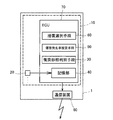
- the injury determination device 10 further includes an ECU 70 having a collision type determination unit 30, a storage unit (storage unit) 40, an injury occurrence rate estimation unit 50, and a measure selection unit 60.
- the injury determination device 10 includes a communication device 80 (which is an example of a notification unit in claims) which is mounted on the vehicle 1 and transmits predetermined information to an external service center or the like.
- the acceleration sensor 20 is mounted on the vehicle 1 and detects acceleration (deceleration) at the time of collision of the vehicle 1.
- the speed sensor 25 is mounted on the vehicle 1 to detect the speed of the vehicle 1.
- the acceleration sensor 20 and the velocity sensor 25 detect (sample) the acceleration and velocity of the vehicle 1 at predetermined intervals, and the detection results (acceleration information and velocity information) are appropriately recorded in the storage unit 40.
- four acceleration sensors 20 and one speed sensor 25 are provided in the vehicle 1.
- a right front sensor 20a and a left front sensor 20b are provided at the front end of the vehicle 1
- a right side sensor 20c and a left side sensor 20d are provided at the center of the vehicle 1 in the front-rear direction.
- the speed sensor 25 is provided in the vicinity of an axle (not shown).
- the number of acceleration sensors 20 mounted on the vehicle 1 is not particularly limited as long as at least one is mounted on the vehicle 1. Further, the position at which the acceleration sensor 20 is provided is not particularly limited, but it is preferable that the position is unlikely to be affected by the deformation of the vehicle 1 at the time of a collision.
- the collision type determination means 30 included in the ECU 70 determines the type of collision of the vehicle 1.
- Examples of the collision form include frontal collision, oblique collision, offset collision, pole collision, and the like.
- the collision type discrimination means 30 discriminates the collision type of the vehicle 1 classified in advance, based on the collision waveform obtained from the detection result of the acceleration sensor 20. That is, it is determined to which collision form the collision of the vehicle 1 belongs.
- the discrimination of the collision mode by the collision mode discriminating means 30 is, for example, for determining the collision mode of the vehicle 1 based on the similarity between the reference waveform corresponding to each collision mode and the collision waveform obtained from the detection result of the acceleration sensor 20. can do.
- the vehicle 1 is provided with a plurality of acceleration sensors 20, but the collision type determination means 30 is based on the detection result of one of the acceleration sensors 20 (20a to 20d).
- the collision mode of the vehicle 1 is determined.
- the collision mode of the vehicle 1 is determined based on the detection result of any one of the acceleration sensors 20a to 20d at which the output at the time of the collision of the vehicle 1 is maximum.
- the determination of the collision type may be based on the detection result of a specific acceleration sensor 20 or may be based on the detection results of a plurality of acceleration sensors 20.
- FIG. 3 is an example of the collision waveform.
- the collision type determination means 30 forms a collision waveform based on the detection result of the acceleration sensor 20 when the collision ends. For example, the acceleration detected by the acceleration sensor 20 is read from the storage unit 40, and the acceleration is integrated twice to obtain the displacement of the vehicle 1. From the acceleration (deceleration) of the vehicle 1 which is the detection result of the acceleration sensor 20 and the displacement of the vehicle 1, for example, a collision waveform as shown in FIG. 3 is formed.
- the collision type determination means 30 compares the obtained collision waveform with the reference waveform corresponding to each collision type to determine the degree of similarity (degree of similarity) of the two. Then, the collision mode of the vehicle 1 is determined from the degree of similarity between the two waveforms obtained for each collision mode. That is, the collision type determination means 30 determines that the collision type having the highest degree of similarity between the collision waveform and each reference waveform is the collision type of the vehicle 1.
- the reference waveform is defined in advance for each type of collision, and the characteristic of the waveform is different for each type of collision such as a frontal collision, an offset collision, and a pole collision. Therefore, by determining the collision form based on the similarity between the collision waveform obtained from the detection result of the acceleration sensor 20 and the plurality of reference waveforms, the collision form of the vehicle 1 can be accurately determined.
- a plurality of reference waveforms corresponding to each type of collision is stored in advance in the storage unit 40.
- the method of forming the reference waveform is not particularly limited, for example, it may be generated based on the result of finite element simulation of the corresponding vehicle.
- the method of determining the degree of similarity between the collision waveform and the reference waveform is not particularly limited.
- the collision type determination means 30 can, for example, compare the reference waveform corresponding to the collision type with the collision waveform, and obtain the similarity based on the residuals of the plurality of feature points of the reference waveform and the collision waveform.
- the residual of each feature point of the reference waveform of the frontal collision and each sampling point of the collision waveform is determined, and the average of the residual (the sum of the residual of each point is sampled Divided by the number of The average of such residuals is also applied to reference waveforms of other collision types. Then, it is determined that the collision form corresponding to the reference waveform that minimizes the average of the residual is the collision form of the vehicle 1.
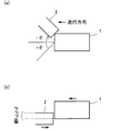
- FIG. 4 is a schematic view showing the positional relationship between a vehicle and an object colliding with the vehicle.
- the collision modes of the vehicle 1 include frontal collisions as described above, but these collision modes can be classified according to the collision angle and the wrap amount.
- the collision angle is an angle formed by a straight line connecting the vehicle 1 and the object 2 based on the traveling direction of the vehicle 1.
- the direct front of the traveling direction of the vehicle 1 is assumed to be zero, the left side of the traveling direction is represented by a positive angle (+ ⁇ ), and the right side is represented by a negative angle ( ⁇ ).
- the amount of lap refers to a range in which the vehicle 1 and the object 2 overlap in the vehicle width direction.
- the ratio of the overlapping range in the vehicle width direction to the vehicle width of the vehicle 1 is taken as the wrap amount. 100% wrap amount is called front full wrap, 40% wrap amount is called front 40% wrap, and 15% wrap amount is called front 15% wrap.
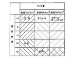
- the collision mode is classified by the combination of the collision angle and the wrap amount.
- a frontal collision (abbreviated as a frontal collision in the figure) is a full front lap, in which the vehicle 1 collides with the object 2 at a collision angle in the range of -15 degrees to +15 degrees.
- the oblique collision (abbreviated as oblique collision in the figure) is a full front lap, and the vehicle 1 collides with the object 2 in the range where the collision angle is +30 degrees or more (not shown in the figure but including -30 degrees or more) It is a form.
- the offset is a front 40% lap, in which the vehicle 1 collides with the object 2 at a collision angle ranging from -15 degrees to +15 degrees.
- Side impact (abbreviated as side impact in the figure) is in the range of front 40% lap to front 15% lap, and the collision angle is 45 degrees or more (not shown in the figure but including -45 degrees or more).
- This is a mode in which the vehicle 1 collides with 2.
- the small overlap has a collision angle in the range of -30 degrees to +30 degrees (-30 degrees omitted in the figure) and a 15% front face wrap, or a collision angle of +30 degrees (not shown in the figure)
- Reference waveforms are created by simulation or the like corresponding to such various types of collisions, and stored in the storage unit 40.
- the ECU 70 reads the speed before and after the detected timing from the storage unit 40, and calculates the speed difference.
- the calculated speed difference is used by the injury incidence rate estimation means 50.
- the injury occurrence rate estimation means 50 included in the ECU 70 estimates the injury occurrence rate of the occupant due to the vehicle collision based on the collision type of the vehicle determined by the collision type determination means 30 and the speed difference detected by the speed sensor 25. .
- the injury incidence rate is the probability that an occupant will be injured due to a collision of the vehicle 1, and is determined based on the type of collision and the speed difference. That is, if the type of collision and the speed difference are determined, the injury incidence rate is identified.
- the injury incidence also means that the higher the rate, the higher the degree of serious injury.
- the memory unit 40 is stored as an injury incidence rate map that represents the relationship between the speed difference before and after the collision of the vehicle and the injury incidence rate. And such an injury incidence rate map is memorized by storage part 40 for every collision form.
- FIG. 6 is a diagram showing an injury incidence rate map for each collision type.
- the horizontal axis represents the collision front / rear speed difference [km / h], and the vertical axis represents the injury incidence rate [%].
- Five injury incidence rate maps M1 to M5 are stored in the storage unit 40 corresponding to the front collision, the oblique collision, the offset, the side collision, and the small overlap, which are five collision modes shown in FIG. There is.
- Each of these injury incidence maps M1 to M5 is defined such that a unique injury incidence is determined for a specific speed difference.
- Such an injury incidence rate map can be obtained, for example, by setting various values to the speed difference ⁇ V for each collision type, executing collision simulation, and totaling the probability that an occupant will be injured.
- the injury incidence rate map is not limited to such a creation method, and a model equation in which the speed difference and the collision mode are used as explanatory variables and the injury incidence rate as a target variable may be used as the injury incidence rate map.
- the injury incidence rate estimation means 50 selects, from the storage unit 40, an injury incidence rate map corresponding to the collision mode when the collision mode is judged by the collision mode judging means 30. Then, an injury occurrence rate corresponding to the speed difference obtained based on the detection result of the speed sensor 25 is determined from the selected injury occurrence rate map.
- the injury occurrence rate estimation unit 50 selects the injury occurrence rate map M1 from the storage unit 40. Then, assuming that the speed difference is ⁇ V, the injury incidence rate estimation means 50 specifies the injury incidence rate p corresponding to ⁇ V from the injury incidence rate map M1. In this way, the occupant's injury incidence rate p is estimated based on the collision type and the speed difference.
- the injury incidence rate p of the occupant estimated by the injury incidence rate estimation means 50 in this manner is used by the action selection means 60.
- the action selection means 60 included in the ECU 70 selects the action corresponding to the injury incidence rate estimated by the injury incidence rate estimation means 50 from the storage unit 40.
- the measures referred to in the present embodiment are measures to be taken according to the condition of the occupant when there is a collision of the vehicle 1. Such measures include, for example, requesting road service (loading service request), reporting occurrence of an accident (accident report), requesting emergency services (emergency services request), doctor helicopter or doctor car Requesting (doctor helicopter request) etc. may be mentioned.
- the action selection means 60 selects an action corresponding to the injury incidence rate estimated by the injury incidence rate estimation means 50 from the storage unit 40.
- the selected action corresponding to the injury incidence rate by the action selection means 60 is an appropriate action to be taken depending on the condition of the occupant after the collision.
- the injury incidence rate is classified by a threshold value, and the measures are stored in the storage unit 40 in advance corresponding to each division. Then, the injury incidence rate estimated by the injury incidence rate estimation means 50 is compared with a threshold, and a measure corresponding to the threshold is selected.
- Table 1 illustrates threshold values and measures.
- the injury incidence also means that the higher the rate, the higher the degree of serious injury. Therefore, as shown in Table 1, the higher the incidence of injury, the more appropriate measures are taken according to the serious injury, and the lower the incidence of injury, the more appropriate is the case where the injury is not serious. ing.
- the action selection means 60 selects the road service request as the action. In addition, if the injury incidence rate is 5% or more and less than 30%, the action selection unit 60 selects an accident report as the action. Similarly, the action selecting means 60 selects an emergency response request as the action if the injury incidence rate is 50% or more and less than 80%, and selects the doctor copter request if the injury incidence rate is 80% or more.
- the measures thus selected are transmitted by the ECU 70 to an external service center or the like via the communication device 80.
- the service center that receives such a measure can respond promptly according to the measure. Not only the measures but also the above-described collision mode and injury incidence rate may be transmitted. Thus, the service center or the like can make the subsequent response more appropriate.
- FIG. 7 is a flowchart showing the processing procedure of the injury determination device 10.
- the collision type determination means 30 determines the type of collision of the vehicle based on the acceleration information from the acceleration sensor 20 (step S1).
- the ECU 70 calculates the speed difference before and after the collision based on the speed information from the speed sensor 25 (step S2).
- the injury incidence rate estimation means 50 estimates the incidence rate of injury based on the collision type determined in step S1 and the speed difference calculated in step S2 (step S3).
- the action selection means 60 selects an action corresponding to the injury incidence rate estimated in step S3 (step S4).
- the ECU 70 reports the action selected in step S4 to an external service center or the like via the communication device 80 (step S5).
- the injury determination device 10 estimates the injury incidence rate of the occupant based on the collision mode and the speed difference of the vehicle, and measures suitable for the occupant's state corresponding to the injury incidence rate. Select and report measures to the outside.
- the injury incidence rate is estimated based on the collision type and speed difference of the vehicle. Therefore, the injury occurrence with higher accuracy than in the prior art in which the collision incidence type is used to estimate the injury incidence rate The rate is obtained. And since appropriate measures are selected for this highly accurate estimated injury incidence rate, more appropriate measures can be taken in comparison with the prior art depending on the degree of actual occupant injury. .
- an injury determination device 10 it is possible to estimate with high accuracy the accident occurrence rate of the occupant due to the collision of the vehicle 1 and to enable appropriate measures according to the injury occurrence rate.
- an external service center or the like since the action to be taken in the event of a collision of a vehicle can be directly obtained, it is possible to take prompt and appropriate action.
- the necessary measures but the collision mode is notified to the outside, so the actual condition of the occupant is unknown, and it is necessary to take necessary measures from the collision mode. For this reason, there was a risk of taking measures that lacked speed and accuracy.
- the injury determination device 10 uses the acceleration sensor 20 and the speed sensor 25 as a configuration for obtaining the speed difference and the collision mode. These sensors are always mounted on a general vehicle 1. Therefore, no special equipment is required to determine the rate of injury occurrence based on the speed difference and the form of collision. As in the prior art, a device for reading information about the occupant is not necessary, and the cost can be reduced.
- the collision angle can be used to determine the collision type.
- the collision angle can be used to distinguish between the positive side and the negative side, that is, the driver side and the passenger side. That is, in the example of FIG. 5, the driver side and the front passenger seat side are grouped into one without having to distinguish between the driver side and the passenger side, but the collision mode may be divided.
- the injury incidence rate maps A1 to An (n is the number of collision types) for the driver side and the injury incidence rate maps B1 to Bn for the passenger side are prepared for each collision type and provided in the storage unit 40.
- the collision mode discrimination means 30 estimates the collision mode called driver side offset, the injury incidence rate map Ai corresponding to the driver side offset and the injury incidence rate map Bi are selected, and the injury incidence rate corresponding to the speed difference Are identified for each of the driver side and the passenger side.
- the injury incidence maps A1 to An correspond to a first injury incidence map in the claims
- the injury incidence maps B1 to Bn correspond to a second injury incidence map in the claims.
- a common injury incidence rate map may be used for all occupants without distinguishing between the driver side and the passenger side.
- the injury determination device 10 uses the injury incidence map in estimating the injury incidence. As a result, since the injury incidence rate can be obtained only by looking up the injury incidence rate corresponding to the speed difference from the storage unit 40, the injury incidence rate can be estimated quickly.
- the injury determination device 10 selects a measure by comparing the injury incidence rate with a threshold.
- a threshold value it is possible to change the action appropriate for the injury incidence rate. For example, even if the actual crew member is a relatively high degree of serious injury, if the appropriate measures are taken against the degree of serious injury, the appropriate action is selected according to the injury incidence rate. Change the value. In this way, the required measures can be flexibly changed.
- the injury determination device 10 forms a collision waveform based on the acceleration information detected by the acceleration sensor 20, and determines the type of collision of the vehicle 1 based on the collision waveform.
- the collision form of the vehicle 1 can be accurately determined by comparing the collision waveform with a reference waveform corresponding to each of the predetermined collision waveforms.
- the reference waveform is defined from the relationship between the displacement of the vehicle 1 and the acceleration at the time of a collision, the difference in waveform characteristics between the collision modes is remarkable, and it is easy to determine the collision mode of the vehicle 1 .
- a total of five collision types are determined, but the number is not limited.
- the collision form was classified and defined by the collision angle and the lap amount, it is not limited to such an aspect.
- the collision type determination means 30 forms a collision waveform based on the displacement and acceleration of the vehicle, and determines the collision type from the collision waveform and the reference waveform, but the collision waveform and the reference waveform are, for example, , And the acceleration of the vehicle. In this case, it is preferable to normalize and compare the collision waveform and the reference waveform.
- the maximum time may be set in consideration of the collision period, and the set maximum time may be normalized as 100%.
- the invention can be used in the automotive sector.
- injury determination device 20 acceleration sensor (acceleration detection means) 25 Speed sensor (speed difference detection means) 30 collision mode determination means 40 storage unit (storage means) 50 injury incidence rate estimating means 60 measure selecting means 80 communication device (reporting means)
Landscapes
- Engineering & Computer Science (AREA)
- Computer Networks & Wireless Communication (AREA)
- Business, Economics & Management (AREA)
- Emergency Management (AREA)
- Physics & Mathematics (AREA)
- General Physics & Mathematics (AREA)
- Mechanical Engineering (AREA)
- Alarm Systems (AREA)
- Traffic Control Systems (AREA)
Abstract
車両1の衝突形態を判別する衝突形態判別手段30と、車両の衝突前後の速度差を検出する速度センサ25と、衝突形態判別手段30により判別された車両の衝突形態、及び速度センサ25により検出した速度差に基づいて、車両の衝突により乗員に傷害が発生する確率である傷害発生率を推定する傷害発生率推定手段50と、傷害発生率に対応して取られるべき措置を記憶した記憶部40と、記憶部40から傷害発生率推定手段50により推定された傷害発生率に対応する措置を選択する措置選択手段60と、措置選択手段60により選択された措置を通報する通信装置80とを備える。
Description
本発明は、車両の衝突による乗員の傷害発生率を推定し、適切な措置を取ることができる傷害判定装置に関する。
従来、車両には、衝突事故が発生した際に、乗員を保護するためのエアバッグ装置が搭載されているものがある。エアバッグ装置は、例えば、車両の衝突が起きた際に、車両の加速度(減速度)を加速度センサで検出し、その検出結果に基づいて所定のタイミングでエアバッグを展開させる。
近年は、車両が衝突した場合に、上記のような加速度センサの検出結果に基づいて、車体の変形の程度や、損壊状況を推定し、その推定結果を外部のサービスセンタ等に知らせるシステム(装置)の開発が進んでいる(例えば、特許文献1、2参照)。
このような装置では、車両の損壊状況等の客観的な情報を外部のサービスセンタ等に迅速に送信することができるので、情報を受信したサービスセンタ等は、車両の損壊状況を正確に把握でき、損壊状況に応じた適切な対応をとることができるとされている。
また、車両の衝突により乗員に傷害が発生することが予測される。そこで、車両の衝突により乗員に傷害が発生する確率(以降、傷害発生率と称する。)を推定する装置が提案されている(例えば、特許文献2参照)。このような装置では、車両の衝突形態、例えば、正面衝突、オフセット衝突、ポール衝突、側面衝突、後方衝突などの衝突形態に基づいて傷害発生率を推定する。さらに、乗員の年齢や性別等の乗員情報が電子的に記録された免許証などのカードを用いて、衝突形態のみならず、乗員情報に基づいても傷害発生率を推定している。
特許文献1に係る装置では、車両の衝突形態が判別され、サービスセンタに通知される。しかしながら、サービスセンタでは乗員が重傷であるかなど傷害の程度が不明であるため、傷害の程度に応じた適切な措置を行いにくいという問題がある。
また、特許文献2に係る装置は、衝突形態に基づいて傷害発生率を推定した結果、高い確率で重傷を負ったと推定する場合がある。しかし、衝突前後の速度に大きな変化がない場合などは、重傷を負わない場合もある。このような場合に対応して、より的確に傷害発生率を推定することが望まれている。
さらに、特許文献2に係る装置では、乗員の情報が記録されたカードを用意することが若干煩雑であり、また、当該カードを読み取る装置が必要となってしまう。このため、そのような乗員情報に依存することなく、傷害発生率を推定することが望まれている。
本発明は上記事情に鑑みてなされたもので、車両の衝突による乗員の傷害発生率をより高精度に推定し、傷害発生率に応じた適切な措置を可能とすることができる傷害判定装置を提供することを目的とする。
上記課題を解決する本発明の第1の態様は、車両の衝突形態を判別する衝突形態判別手段と、車両の衝突前後の速度差を検出する速度差検出手段と、前記衝突形態判別手段により判別された車両の衝突形態、及び前記速度差検出手段により検出した速度差に基づいて、車両の衝突により乗員に傷害が発生する確率である傷害発生率を推定する傷害発生率推定手段と、傷害発生率に対応して取られるべき措置を記憶した記憶手段と、前記記憶手段から前記傷害発生率推定手段により判定された傷害発生率に対応する措置を選択する措置選択手段と、前記措置選択手段により選択された措置を通報する通報手段と、を備えることを特徴とする傷害判定装置にある。
かかる第1の態様では、車両の衝突による乗員の傷害発生率をより高精度に推定し、傷害発生率に応じた適切な措置を可能とすることができる。また、外部のサービスセンタ等では、車両の衝突に対して取るべき措置が直接的に得られるので、迅速かつ適切な措置をとることができる。
本発明の第2の態様は、第1の態様に記載する傷害判定装置において、前記記憶手段には、車両の衝突前後の速度差と前記傷害発生率との関係を表す傷害発生率マップが前記衝突形態ごとに記憶され、前記傷害発生率推定手段は、前記衝突形態判別手段により判別された車両の衝突形態に対応する傷害発生率マップを前記記憶手段から選択し、選択した傷害発生率マップから前記速度差検出手段により検出した速度差に対応する傷害発生率を求めることを特徴とする傷害判定装置にある。
かかる第2の態様では、傷害発生率の推定を速やかに行うことができる。
本発明の第3の態様は、第2の態様に記載する傷害判定装置において、前記傷害発生率マップは、前記車両の衝突前後の速度差に基づき前記衝突形態ごとに衝突シミュレーションを実行し、前記乗員に傷害が発生する確率を集計することにより作成されることを特徴とする傷害判定装置にある。
かかる第3の態様では、衝突形態ごとにより正確な傷害発生率マップを作成することが可能となる。
本発明の第4の態様は、第1から第3の何れか一つの態様に記載する傷害判定装置において、前記記憶手段は、しきい値で区分された傷害発生率ごとに異なる措置が記憶され、前記措置選択手段は、前記傷害発生率推定手段により判定された傷害発生率を前記しきい値と比較し、前記しきい値に対応する措置を選択することを特徴とする傷害判定装置にある。
かかる第4の態様では、しきい値を変更することで必要となる措置を柔軟に変更することができる。
本発明の第5の態様は、第1から第4の何れか一つの態様に記載する傷害判定装置において、車両の衝突時の加速度を検出する加速度検出手段を備え、前記衝突形態判別手段は、前記加速度検出手段の検出結果から得られる衝突波形に基づいて車両の衝突形態を判別することを特徴とする傷害判定装置にある。
かかる第5の態様では、車両の衝突形態を正確に判別することができる。
本発明の第6の態様は、第1から第5のいずれか1つの態様に記載する傷害判定装置において、前記衝突形態には、車両に衝突する対象物との成す衝突角度が車両の運転者側又は助手席側である衝突形態を含み、前記記憶手段には、運転者側に搭乗する乗員についての第1傷害発生率マップ、及び助手席側に搭乗する乗員についての第2傷害発生率マップが記憶され、前記傷害発生率推定手段は、衝突角度が運転者側又は助手席側である衝突形態が検出されたとき、当該衝突形態に対応した傷害発生率を、前記第1傷害発生率マップ、及び第2傷害発生率マップのそれぞれについて推定することを特徴とする傷害判定装置にある。
かかる第6の態様では、衝突角度を考慮して衝突形態を分けることで、乗員の位置ごとに傷害発生率を推定することができる。そして、乗員毎に傷害発生率に基づいて措置が選択されるので、各乗員に適した措置を取ることができる。
本発明によれば、車両の衝突による乗員の傷害発生率をより高精度に推定し、傷害発生率に応じた適切な措置を可能とすることができる傷害判定装置が提供される。
〈実施形態1〉
以下、本発明を実施するための形態について説明する。なお、実施形態の説明は例示であり、本発明は以下の説明に限定されない。
以下、本発明を実施するための形態について説明する。なお、実施形態の説明は例示であり、本発明は以下の説明に限定されない。
図1及び図2に示すように、本実施形態に係る傷害判定装置10は、車両1が衝突した際に、乗員の重傷度を判定し、重傷度に応じた措置を選択する装置である。具体的には、傷害判定装置10は、車両1に搭載された加速度センサ(加速度検出手段)20及び速度センサ(速度差検出手段)25を備えている。また、傷害判定装置10は、衝突形態判別手段30と、記憶部(記憶手段)40と、傷害発生率推定手段50と、措置選択手段60とを有するECU70を備えている。また、傷害判定装置10は、車両1に搭載され、外部のサービスセンタ等に所定の情報を送信する通信装置80(請求項の通報手段の一例である)を備えている。
加速度センサ20は、車両1に搭載されて車両1の衝突時の加速度(減速度)を検出する。また、速度センサ25は、車両1に搭載されて車両1の速度を検出する。加速度センサ20及び速度センサ25は、所定の間隔で車両1の加速度及び速度を検出(サンプリング)しており、各検出結果(加速度情報及び速度情報)は記憶部40に適宜記録される。
本実施形態では、4つの加速度センサ20と1つの速度センサ25とが車両1に設けられている。例えば、車両1の前端部に、右フロントセンサ20a及び左フロントセンサ20bが設けられ、車両1の前後方向中央部に、右サイドセンサ20c及び左サイドセンサ20dがそれぞれ設けられている。また、速度センサ25は図示しない車軸近傍に設けられている。
車両1に搭載する加速度センサ20の数は特に限定されず、車両1に少なくとも一つ搭載されていればよい。また加速度センサ20を設ける位置も特に限定されないが、衝突時に車両1の変形の影響を受けにくい位置であることが好ましい。
ECU70が備える衝突形態判別手段30は、車両1の衝突形態を判別する。衝突形態としては、例えば、正面衝突、斜め衝突、オフセット衝突、ポール衝突等が挙げられる。具体的には、衝突形態判別手段30は、車両1が衝突した際に、加速度センサ20の検出結果から得られる衝突波形に基づいて、予め類別した車両1の衝突形態を判別する。すなわち、車両1の衝突が何れの衝突形態に属するかを判別する。
衝突形態判別手段30による衝突形態の判別は、例えば、各衝突形態に対応する基準波形と、加速度センサ20の検出結果から得られた衝突波形との相似度に基づいて車両1の衝突形態を判別することができる。
なお、本実施形態では、車両1に複数の加速度センサ20が設けられているが、衝突形態判別手段30は、このうちの何れか一つの加速度センサ20(20a~20d)の検出結果に基づいて車両1の衝突形態を判別する。例えば、車両1の衝突時の出力が最大である加速度センサ20a~20dの何れかの検出結果に基づいて車両1の衝突形態を判別する。勿論、衝突形態の判別は、特定の加速度センサ20の検出結果に基づくものであってもよいし、複数の加速度センサ20の検出結果に基づくものであってもよい。
衝突形態判別手段30による衝突形態の判別手順について説明する。なお図3は衝突波形の一例である。
衝突形態判別手段30は、車両1の衝突が起こると、衝突が終了した時点で、加速度センサ20の検出結果に基づいて衝突波形を形成する。例えば、加速度センサ20が検出した加速度を記憶部40から読み出し、当該加速度を2回積分して車両1の変位を得る。このような加速度センサ20の検出結果である車両1の加速度(減速度)と、車両1の変位とから、例えば、図3に示すような衝突波形を形成する。
次に、衝突形態判別手段30は、得られた衝突波形を、各衝突形態に対応する基準波形と比較し、両者の相似度(相似の程度)を求める。そして、衝突形態毎に求められた両波形の相似度から車両1の衝突形態を判別する。すなわち、衝突形態判別手段30は、衝突波形と各基準波形との相似度が最も高い衝突形態を車両1の衝突形態であると判別する。
基準波形は、衝突形態毎に予め規定したものであり、正面衝突、オフセット衝突、ポール衝突等の各衝突形態で波形の特徴が異なる。このため、加速度センサ20の検出結果から得られた衝突波形と複数の各基準波形との相似度に基づいて衝突形態を判別することで、車両1の衝突形態を正確に判別することができる。
このような各衝突形態に対応する複数の基準波形は、記憶部40に予め記憶されている。なお基準波形の形成方法は、特に限定されないが、例えば、該当車両の有限要素シミュレーションの結果に基づいて作成すればよい。
衝突波形と基準波形との相似度の求め方は、特に限定されない。衝突形態判別手段30は、例えば、衝突形態に対応する基準波形と衝突波形とを比較し、基準波形の複数の特徴点と衝突波形との残差に基づいて相似度を求めることができる。
具体的には、図示するように、正面衝突の基準波形の各特徴点と、衝突波形の各サンプリング点との残差を求め、当該残差の平均(各点の残差の和をサンプリング点の数で割ったもの)を求める。このような残差の平均を他の衝突形態の基準波形についても実施する。そして、残差の平均が最小となる基準波形に対応する衝突形態が、車両1の衝突形態であると判別する。
本実施形態の衝突形態について説明する。図4は、車両と車両に衝突する対象物との位置関係を示す概略図である。
車両1の衝突形態としては、上述したように正面衝突等があるが、これらの衝突形態は、衝突角度及びラップ量で分別できる。衝突角度は、車両1の進行方向を基準として、車両1と対象物2とを結ぶ直線のなす角度である。車両1の進行方向の真正面をゼロ度とし、進行方向の左側を正の角度(+θ)、右側を負の角度(-θ)で表す。また、ラップ量は、車両1と対象物2とが車幅方向で重なる範囲をいう。ここでは、車両1の車幅に対して、車幅方向で重なる範囲の割合をラップ量とする。ラップ量が100%を前面フルラップ、ラップ量が40%を前面40%ラップ、ラップ量が15%を前面15%ラップと称する。
図5に示すように、衝突角度とラップ量との組み合わせにより衝突形態が分類される。例えば、正面衝突(図では正突と略記)は、前面フルラップであり、衝突角度が-15度~+15度の範囲で対象物2に車両1が衝突した形態である。斜め衝突(図では斜突と略記)は、前面フルラップであり、衝突角度が+30度以上(図では省略しているが-30度以上も含む)の範囲で対象物2に車両1が衝突した形態である。オフセットは、前面40%ラップであり、衝突角度が-15度~+15度の範囲で対象物2に車両1が衝突した形態である。側面衝突(図では側突と略記)は、前面40%ラップ~前面15%ラップの範囲であり、衝突角度が45度以上(図では省略しているが-45度以上も含む)で対象物2に車両1が衝突した形態である。スモールオーバーラップは、衝突角度が-30度~+30度の範囲(図では-30度は省略してある)かつ前面15%ラップであるか、衝突角度が+30度(図では省略しているが-30度も含む)かつ前面40%ラップで対象物2に車両1が衝突した形態である。
このような様々な衝突形態に対応して基準波形がシミュレーション等で作成されて、記憶部40に記憶されている。
このようにして衝突形態判別手段30により衝突形態が検出されたとき、ECU70は、その検出されたタイミングの前後における速度を記憶部40から読み取り、速度差を計算する。計算した速度差は、傷害発生率推定手段50で用いられる。
ECU70が備える傷害発生率推定手段50は、衝突形態判別手段30により判別された車両の衝突形態、及び速度センサ25により検出した速度差に基づいて、車両の衝突による乗員の傷害発生率を推定する。
傷害発生率とは、車両1の衝突により乗員に傷害が発生する確率であり、衝突形態及び速度差に基づいて定まる。すなわち、衝突形態及び速度差が定まれば傷害発生率が特定される。また、傷害発生率は、率が高いほど重傷である度合いが高いことも意味している。
本実施形態では、車両の衝突前後の速度差と傷害発生率との関係を表す傷害発生率マップとして記憶部40に記憶されている。そしてこのような傷害発生率マップは、衝突形態毎に記憶部40に記憶されている。
図6は、衝突形態ごとの傷害発生率マップを示す図である。横軸は、衝突前後速度差[km/h]を表し、縦軸は傷害発生率[%]を表している。図5に示した5つの衝突形態である、正面衝突、斜め衝突、オフセット、側面衝突、スモールオーバーラップのそれぞれに対応して、5つの傷害発生率マップM1~M5が記憶部40に記憶されている。これらの各傷害発生率マップM1~M5は、特定の速度差に対して一意の傷害発生率が定まるように定義されている。
このような傷害発生率マップは、例えば、衝突形態ごとに速度差ΔVに様々な値を設定して衝突シミュレーションを実行し、乗員に傷害が発生する確率を集計することにより得ることができる。もちろん、傷害発生率マップはこのような作成方法に限定されず、速度差及び衝突形態を説明変数とし、傷害発生率を目的変数とするようなモデル式を傷害発生率マップとしてもよい。
傷害発生率推定手段50は、衝突形態判別手段30により衝突形態が判別されたとき、当該衝突形態に対応する傷害発生率マップを記憶部40から選択する。そして、選択した傷害発生率マップから速度センサ25の検出結果に基づいて得られた速度差に対応する傷害発生率を求める。
例えば、衝突形態が正面衝突であると判別されたとき、傷害発生率推定手段50は、記憶部40から傷害発生率マップM1を選択する。そして、速度差がΔVであったとすると、傷害発生率推定手段50は、傷害発生率マップM1からΔVに対応する傷害発生率pを特定する。このようにして、衝突形態及び速度差に基づいて、乗員の傷害発生率pが推定される。
このように傷害発生率推定手段50により推定された乗員の傷害発生率pは、措置選択手段60により用いられる。
ECU70が備える措置選択手段60は、記憶部40から傷害発生率推定手段50により推定された傷害発生率に対応する措置を選択する。本実施形態でいう措置とは、車両1の衝突があった際に、乗員の状態に応じて取るべき措置である。このような措置は、例えば、ロードサービスを要請すること(ロードサービス要請)、事故の発生を通報すること(事故通報)、救急隊を要請すること(救急隊要請)、ドクターヘリ又はドクターカーを要請すること(ドクターヘリ要請)などが挙げられる。
このような各種の措置は、傷害発生率に対応して記憶部40に記憶されている。措置選択手段60は、傷害発生率推定手段50で推定された傷害発生率に対応する措置を記憶部40から選択する。
傷害発生率は、衝突時の乗員の状態、すなわち、どの程度の傷を負っているかを推定したものである。したがって、措置選択手段60が傷害発生率に対応した選択した措置は、衝突後の乗員の状態に応じて取るべき適切な措置となる。
傷害発生率から措置を選択する具体的な方法としては、しきい値で傷害発生率を区分し、その区分毎に措置を予め対応させて記憶部40に記憶させておく。そして、傷害発生率推定手段50により推定された傷害発生率としきい値とを比較し、そのしきい値に対応する措置を選択する。
表1にしきい値と措置とを例示する。

上述したように、傷害発生率は、率が高いほど重傷である度合いが高いことも意味している。したがって、表1に示すように、傷害発生率が高いほど、重傷に応じた適切な措置が対応づけられており、傷害発生率が低いほど、それほど重傷ではない場合に適切な措置が対応づけられている。
措置選択手段60は、傷害発生率が5%未満であれば、措置としてロードサービス要請を選択する。また、措置選択手段60は、傷害発生率が5%以上30%未満であれば、措置として事故通報を選択する。同様に、措置選択手段60は、傷害発生率が50%以上80%未満であれば、措置として救急隊要請を選択し、傷害発生率が80%以上であればドクターヘリ要請を選択する。
このように選択された措置は、ECU70により通信装置80を介して外部のサービスセンタ等に送信される。このような措置を受け取ったサービスセンタでは、当該措置にしたがって、迅速に対応することができる。なお、措置のみならず、上述した衝突形態や傷害発生率を含めて送信してもよい。これにより、サービスセンタ等では、その後の対応をさらに適切なものとすることができる。
以下、傷害判定装置10における処理手順について説明する。なお図7は、傷害判定装置10の処理手順を示すフローチャートである。
まず、衝突形態判別手段30は、車両1の衝突があったとき、加速度センサ20による加速度情報に基づいて車両の衝突形態を判別する(ステップS1)。次に、ECU70は、速度センサ25による速度情報に基づいて衝突前後の速度差を計算する(ステップS2)。次に、傷害発生率推定手段50は、ステップS1で判別した衝突形態及びステップS2で計算した速度差に基づいて、傷害発生率を推定する(ステップS3)。次に、措置選択手段60は、ステップS3で推定された傷害発生率に対応する措置を選択する(ステップS4)。最後に、ECU70は、ステップS4で選択された措置を通信装置80を介して外部のサービスセンタ等に通報する(ステップS5)。
以上に説明した本実施形態に係る傷害判定装置10は、車両の衝突形態及び速度差に基づいて乗員の傷害発生率を推定し、当該傷害発生率に対応して、乗員の状態に適した措置を選択し、外部に措置を通報する。
傷害判定装置10によれば、車両の衝突形態及び速度差に基づいて傷害発生率を推定するので、衝突形態を用いて傷害発生率を推定する従来技術と比較して、より高精度な傷害発生率が得られる。そして、この高精度に推定された傷害発生率に対して、適切な措置を選択するので、実際の乗員の傷害の程度に応じて、従来技術と比較してより適切な措置を取ることができる。
このような傷害判定装置10によれば、車両1の衝突による乗員の傷害発生率をより高精度に推定し、傷害発生率に応じた適切な措置を可能とすることができる。また、外部のサービスセンタ等では、車両の衝突に対して取るべき措置が直接的に得られるので、迅速かつ適切な措置をとることができる。なお、従来技術では、必要な措置ではなく、衝突形態が外部に通報されるので、実際の乗員の状態については不明であり、衝突形態から必要な措置を講じる必要があった。このため、迅速性や正確性に欠けた措置を取るおそれがあった。
上述したように、傷害発生率を推定するにあたり速度差を用いることで高精度な推定を実現した。これは、速度差を考慮することで、例えば、衝突前後の速度に大きな変化がない場合は傷害が発生する可能性が低い、という事態についても的確に推定できるからである。逆に衝突前後の速度に大きな変化がある場合は、傷害が発生する可能性が非常に高い、という事態についても的確に推定できるからである。
そして、このような傷害発生率を衝突形態ごとに推定した。これにより、同じ速度差であっても、衝突形態によっては傷害発生率が大きく異なる、という事態を的確に推定できる。
また、傷害判定装置10は、速度差及び衝突形態を得るための構成としては、加速度センサ20及び速度センサ25を用いた。これらのセンサは、一般的な車両1には必ず搭載されている。したがって、速度差及び衝突形態に基づいて傷害発生率を求めるにあたって、特別な装置を必要としない。従来技術のように乗員に関する情報を読み取るための装置が不要になり、コストを削減することができる。
さらに、図5に示したように、衝突形態の判別にあたっては衝突角度を用いることができることを説明した。衝突角度は、+側と-側、すなわち運転者側、助手席側を区別するために用いることができる。つまり、図5の例では、運転者側及び助手席側を区別せずにオフセットなど一つに纏めていたが、衝突形態を分けてもよい。
例えば、0度から-15度までを運転者側オフセット、0度から+15度までを助手席側オフセットという二つの衝突形態に分けてもよい。そして、運転者側に関する傷害発生率マップA1~An(nは衝突形態の数)、助手席側に関する傷害発生率マップB1~Bnを衝突形態ごとに作成して記憶部40に設けておく。衝突形態判別手段30により、運転者側オフセットという衝突形態が推定されたとき、運転者側オフセットに対応した傷害発生率マップAi、傷害発生率マップBiを選択し、速度差に対応した傷害発生率を運転者側及び助手席側のそれぞれについて特定する。
このように衝突角度を考慮して衝突形態を分けることで、乗員の位置ごとに傷害発生率を推定することができる。そして、乗員毎に傷害発生率に基づいて措置が選択されるので、各乗員に適した措置を取ることができる。
なお、傷害発生率マップA1~Anは請求項の第1傷害発生率マップに相当し、傷害発生率マップB1~Bnは請求項の第2傷害発生率マップに相当する。また、運転者側や助手席側を区別せずに、全ての乗員に対して共通の傷害発生率マップを用いてもよい。
傷害判定装置10は、傷害発生率を推定するに当たり、傷害発生率マップを用いた。これにより、記憶部40から速度差に対応する傷害発生率をルックアップするだけで傷害発生率を得ることができるので、傷害発生率の推定を速やかに行うことができる。
傷害判定装置10は、傷害発生率をしきい値と比較することで措置を選択した。これにより、しきい値を変更すれば、傷害発生率に適した措置を変更することができる。例えば、実際の乗員は比較的高度な重傷であるにも関わらず、その重傷の度合いに対して適切でない措置がなされた場合、傷害発生率に対応して適切な措置が選択されるようにしきい値を変更すればよい。このように、必要となる措置を柔軟に変更することができる。
傷害判定装置10は、加速度センサ20により検出された加速度情報に基づいて衝突波形を形成し、当該衝突波形に基づいて車両1の衝突形態を判別した。具体的には、この衝突波形を予め規定した各衝突波形に対応した基準波形と比較することで、車両1の衝突形態を正確に判別することができる。特に、基準波形が、衝突時の車両1の変位と加速度との関係から規定されたものである場合、衝突形態毎の波形の特徴の違いが顕著であり、車両1の衝突形態を判別し易い。
以上、本発明の一実施形態について説明したが、本発明は上述の実施形態に限定されるものではない。本発明は、その趣旨を逸脱しない範囲で適宜変更が可能なものである。
例えば、上述の実施形態では、衝突形態は合計5個定められていたが、数に限定はない。また、衝突形態は、衝突角度及びラップ量により分類されて定められていたが、このような態様に限定されない。
また、衝突形態判別手段30が、車両の変位と加速度とに基づいて衝突波形を形成し、この衝突波形と基準波形とから衝突形態を判別するようにしたが、衝突波形及び基準波形は、例えば、時間と車両の加速度とから形成されたものであってもよい。この場合には、衝突波形及び基準波形を正規化して比較することが好ましい。なお、時間に関しては、衝突期間を考慮して最大時間を設定し、設定した最大時間を100%として正規化すればよい。
本発明は、自動車の産業分野で利用することができる。
10 傷害判定装置
20 加速度センサ(加速度検出手段)
25 速度センサ(速度差検出手段)
30 衝突形態判別手段
40 記憶部(記憶手段)
50 傷害発生率推定手段
60 措置選択手段
80 通信装置(通報手段)
20 加速度センサ(加速度検出手段)
25 速度センサ(速度差検出手段)
30 衝突形態判別手段
40 記憶部(記憶手段)
50 傷害発生率推定手段
60 措置選択手段
80 通信装置(通報手段)
Claims (6)
- 車両の衝突形態を判別する衝突形態判別手段と、
車両の衝突前後の速度差を検出する速度差検出手段と、
前記衝突形態判別手段により判別された車両の衝突形態、及び前記速度差検出手段により検出した速度差に基づいて、車両の衝突により乗員に傷害が発生する確率である傷害発生率を推定する傷害発生率推定手段と、
傷害発生率に対応して取られるべき措置を記憶した記憶手段と、
前記記憶手段から前記傷害発生率推定手段により推定された傷害発生率に対応する措置を選択する措置選択手段と、
前記措置選択手段により選択された措置を通報する通報手段と、を備える
ことを特徴とする傷害判定装置。 - 請求項1に記載する傷害判定装置において、
前記記憶手段には、車両の衝突前後の速度差と前記傷害発生率との関係を表す傷害発生率マップが前記衝突形態ごとに記憶され、
前記傷害発生率推定手段は、前記衝突形態判別手段により判別された車両の衝突形態に対応する傷害発生率マップを前記記憶手段から選択し、選択した傷害発生率マップから前記速度差検出手段により検出した速度差に対応する傷害発生率を求める
ことを特徴とする傷害判定装置。 - 請求項2に記載する傷害判定装置において、
前記傷害発生率マップは、前記車両の衝突前後の速度差に基づき前記衝突形態ごとに衝突シミュレーションを実行し、前記乗員に傷害が発生する確率を集計することにより作成される
ことを特徴とする傷害判定装置。 - 請求項1から請求項3の何れか一項に記載する傷害判定装置において、
前記記憶手段は、しきい値で区分された傷害発生率ごとに異なる措置が記憶され、
前記措置選択手段は、前記傷害発生率推定手段により推定された傷害発生率を前記しきい値と比較し、前記しきい値に対応する措置を選択する
ことを特徴とする傷害判定装置。 - 請求項1から請求項4の何れか一項に記載する傷害判定装置において、
車両の衝突時の加速度を検出する加速度検出手段を備え、
前記衝突形態判別手段は、前記加速度検出手段の検出結果から得られる衝突波形に基づいて車両の衝突形態を判別する
ことを特徴とする傷害判定装置。 - 請求項1から請求項5の何れか一項に記載する傷害判定装置において、
前記衝突形態には、車両に衝突する対象物との成す衝突角度が車両の運転者側又は助手席側である衝突形態を含み、
前記記憶手段には、運転者側に搭乗する乗員についての第1傷害発生率マップ、及び助手席側に搭乗する乗員についての第2傷害発生率マップが記憶され、
前記傷害発生率推定手段は、衝突角度が運転者側又は助手席側である衝突形態が検出されたとき、当該衝突形態に対応した傷害発生率を、前記第1傷害発生率マップ、及び第2傷害発生率マップのそれぞれについて推定する
ことを特徴とする傷害判定装置。
Applications Claiming Priority (2)
| Application Number | Priority Date | Filing Date | Title |
|---|---|---|---|
| JP2015146150A JP6607347B2 (ja) | 2015-07-23 | 2015-07-23 | 傷害判定装置 |
| JP2015-146150 | 2015-07-23 |
Publications (1)
| Publication Number | Publication Date |
|---|---|
| WO2017014081A1 true WO2017014081A1 (ja) | 2017-01-26 |
Family
ID=57833935
Family Applications (1)
| Application Number | Title | Priority Date | Filing Date |
|---|---|---|---|
| PCT/JP2016/070340 Ceased WO2017014081A1 (ja) | 2015-07-23 | 2016-07-08 | 傷害判定装置 |
Country Status (2)
| Country | Link |
|---|---|
| JP (1) | JP6607347B2 (ja) |
| WO (1) | WO2017014081A1 (ja) |
Cited By (2)
| Publication number | Priority date | Publication date | Assignee | Title |
|---|---|---|---|---|
| CN111923859A (zh) * | 2020-07-28 | 2020-11-13 | 江苏大学 | 一种正面碰撞下后排乘员伤情预测及对外呼救方法及其系统 |
| CN112829742A (zh) * | 2020-12-30 | 2021-05-25 | 清华大学 | 乘员安全决策方法和装置 |
Families Citing this family (1)
| Publication number | Priority date | Publication date | Assignee | Title |
|---|---|---|---|---|
| WO2022195817A1 (ja) * | 2021-03-18 | 2022-09-22 | 本田技研工業株式会社 | 車両、車両診断システム及び車両診断方法 |
Citations (5)
| Publication number | Priority date | Publication date | Assignee | Title |
|---|---|---|---|---|
| JP2002031544A (ja) * | 2000-07-17 | 2002-01-31 | Omron Corp | 情報処理装置および方法、並びに記録媒体 |
| JP2003040061A (ja) * | 2001-07-30 | 2003-02-13 | Mazda Motor Corp | 車両事故解析装置 |
| JP2004078393A (ja) * | 2002-08-13 | 2004-03-11 | Nec Fielding Ltd | 交通事故緊急対応システムおよび交通事故緊急対応プログラム |
| JP2005263178A (ja) * | 2004-03-22 | 2005-09-29 | Denso Corp | 車両衝突解析システム |
| JP2013166515A (ja) * | 2012-02-16 | 2013-08-29 | Mitsubishi Motors Corp | 衝突判別装置 |
-
2015
- 2015-07-23 JP JP2015146150A patent/JP6607347B2/ja active Active
-
2016
- 2016-07-08 WO PCT/JP2016/070340 patent/WO2017014081A1/ja not_active Ceased
Patent Citations (5)
| Publication number | Priority date | Publication date | Assignee | Title |
|---|---|---|---|---|
| JP2002031544A (ja) * | 2000-07-17 | 2002-01-31 | Omron Corp | 情報処理装置および方法、並びに記録媒体 |
| JP2003040061A (ja) * | 2001-07-30 | 2003-02-13 | Mazda Motor Corp | 車両事故解析装置 |
| JP2004078393A (ja) * | 2002-08-13 | 2004-03-11 | Nec Fielding Ltd | 交通事故緊急対応システムおよび交通事故緊急対応プログラム |
| JP2005263178A (ja) * | 2004-03-22 | 2005-09-29 | Denso Corp | 車両衝突解析システム |
| JP2013166515A (ja) * | 2012-02-16 | 2013-08-29 | Mitsubishi Motors Corp | 衝突判別装置 |
Cited By (2)
| Publication number | Priority date | Publication date | Assignee | Title |
|---|---|---|---|---|
| CN111923859A (zh) * | 2020-07-28 | 2020-11-13 | 江苏大学 | 一种正面碰撞下后排乘员伤情预测及对外呼救方法及其系统 |
| CN112829742A (zh) * | 2020-12-30 | 2021-05-25 | 清华大学 | 乘员安全决策方法和装置 |
Also Published As
| Publication number | Publication date |
|---|---|
| JP2017024604A (ja) | 2017-02-02 |
| JP6607347B2 (ja) | 2019-11-20 |
Similar Documents
| Publication | Publication Date | Title |
|---|---|---|
| CN101612938B (zh) | 用于车辆安全系统的判断线计算 | |
| US6327527B1 (en) | Activation control apparatus of occupant safety system | |
| JP7645668B2 (ja) | 重み付きアクティブ-パッシブ衝突モード分類を実行する車両安全システムおよび方法 | |
| CN109050538B (zh) | 一种安全车距估算装置及方法 | |
| EP3098130B1 (en) | Vehicle speed control apparatus and vehicle speed limiting apparatus | |
| US20130158809A1 (en) | Method and system for estimating real-time vehicle crash parameters | |
| US11238731B2 (en) | Method and device for detecting the passage of a motor vehicle through a road sign gantry | |
| CN115123263B (zh) | 车辆行驶跑偏的控制方法、整车控制器及车辆 | |
| US7422087B2 (en) | Method and system for detecting vehicle rollover events | |
| CN107161144A (zh) | 车辆碰撞系统及其使用方法 | |
| JP4878370B2 (ja) | 乗員保護装置のためのロール角算出の方法および装置 | |
| WO2017014081A1 (ja) | 傷害判定装置 | |
| JP5854426B2 (ja) | 衝突判別装置 | |
| JPH10239334A (ja) | 初期補正係数演算装置 | |
| CN101945781A (zh) | 用于触发车辆的人员保护装置的方法和控制装置 | |
| CN105377636B (zh) | 用于控制车辆中的人员防护装置的设备 | |
| CN105523084A (zh) | 一种基于三轴加速度传感器检测车辆转弯角度的方法 | |
| CN107644475A (zh) | 一种车辆碰撞检测的方法和装置以及obd盒子 | |
| JP2001264132A (ja) | センサ異常検出方法及びセンサ異常検出装置及び車両制御装置 | |
| CN109963753B (zh) | 用于识别车辆碰撞的方法和设备 | |
| JP6150051B2 (ja) | 乗員状態判定装置 | |
| CN117508211A (zh) | 运行惯性测量单元的方法、惯性测量单元和车辆控制系统 | |
| US7376502B2 (en) | Device for triggering a restraining system in a vehicle | |
| CN109367507A (zh) | 一种安全系统管理装置和管理方法 | |
| JP2013033461A (ja) | 運転状態診断装置 |
Legal Events
| Date | Code | Title | Description |
|---|---|---|---|
| 121 | Ep: the epo has been informed by wipo that ep was designated in this application |
Ref document number: 16827643 Country of ref document: EP Kind code of ref document: A1 |
|
| NENP | Non-entry into the national phase |
Ref country code: DE |
|
| 122 | Ep: pct application non-entry in european phase |
Ref document number: 16827643 Country of ref document: EP Kind code of ref document: A1 |