WO2017010388A1 - Power conversion device - Google Patents
Power conversion device Download PDFInfo
- Publication number
- WO2017010388A1 WO2017010388A1 PCT/JP2016/070076 JP2016070076W WO2017010388A1 WO 2017010388 A1 WO2017010388 A1 WO 2017010388A1 JP 2016070076 W JP2016070076 W JP 2016070076W WO 2017010388 A1 WO2017010388 A1 WO 2017010388A1
- Authority
- WO
- WIPO (PCT)
- Prior art keywords
- voltage
- power converter
- converter
- power
- current
- Prior art date
Links
Images


Classifications
-
- H—ELECTRICITY
- H02—GENERATION; CONVERSION OR DISTRIBUTION OF ELECTRIC POWER
- H02M—APPARATUS FOR CONVERSION BETWEEN AC AND AC, BETWEEN AC AND DC, OR BETWEEN DC AND DC, AND FOR USE WITH MAINS OR SIMILAR POWER SUPPLY SYSTEMS; CONVERSION OF DC OR AC INPUT POWER INTO SURGE OUTPUT POWER; CONTROL OR REGULATION THEREOF
- H02M7/00—Conversion of ac power input into dc power output; Conversion of dc power input into ac power output
- H02M7/42—Conversion of dc power input into ac power output without possibility of reversal
- H02M7/44—Conversion of dc power input into ac power output without possibility of reversal by static converters
- H02M7/48—Conversion of dc power input into ac power output without possibility of reversal by static converters using discharge tubes with control electrode or semiconductor devices with control electrode
- H02M7/483—Converters with outputs that each can have more than two voltages levels
- H02M7/4835—Converters with outputs that each can have more than two voltages levels comprising two or more cells, each including a switchable capacitor, the capacitors having a nominal charge voltage which corresponds to a given fraction of the input voltage, and the capacitors being selectively connected in series to determine the instantaneous output voltage
-
- H—ELECTRICITY
- H02—GENERATION; CONVERSION OR DISTRIBUTION OF ELECTRIC POWER
- H02M—APPARATUS FOR CONVERSION BETWEEN AC AND AC, BETWEEN AC AND DC, OR BETWEEN DC AND DC, AND FOR USE WITH MAINS OR SIMILAR POWER SUPPLY SYSTEMS; CONVERSION OF DC OR AC INPUT POWER INTO SURGE OUTPUT POWER; CONTROL OR REGULATION THEREOF
- H02M1/00—Details of apparatus for conversion
- H02M1/08—Circuits specially adapted for the generation of control voltages for semiconductor devices incorporated in static converters
- H02M1/084—Circuits specially adapted for the generation of control voltages for semiconductor devices incorporated in static converters using a control circuit common to several phases of a multi-phase system
- H02M1/0845—Circuits specially adapted for the generation of control voltages for semiconductor devices incorporated in static converters using a control circuit common to several phases of a multi-phase system digitally controlled (or with digital control)
-
- H—ELECTRICITY
- H02—GENERATION; CONVERSION OR DISTRIBUTION OF ELECTRIC POWER
- H02M—APPARATUS FOR CONVERSION BETWEEN AC AND AC, BETWEEN AC AND DC, OR BETWEEN DC AND DC, AND FOR USE WITH MAINS OR SIMILAR POWER SUPPLY SYSTEMS; CONVERSION OF DC OR AC INPUT POWER INTO SURGE OUTPUT POWER; CONTROL OR REGULATION THEREOF
- H02M1/00—Details of apparatus for conversion
- H02M1/12—Arrangements for reducing harmonics from ac input or output
-
- H—ELECTRICITY
- H02—GENERATION; CONVERSION OR DISTRIBUTION OF ELECTRIC POWER
- H02M—APPARATUS FOR CONVERSION BETWEEN AC AND AC, BETWEEN AC AND DC, OR BETWEEN DC AND DC, AND FOR USE WITH MAINS OR SIMILAR POWER SUPPLY SYSTEMS; CONVERSION OF DC OR AC INPUT POWER INTO SURGE OUTPUT POWER; CONTROL OR REGULATION THEREOF
- H02M1/00—Details of apparatus for conversion
- H02M1/32—Means for protecting converters other than automatic disconnection
-
- H—ELECTRICITY
- H02—GENERATION; CONVERSION OR DISTRIBUTION OF ELECTRIC POWER
- H02M—APPARATUS FOR CONVERSION BETWEEN AC AND AC, BETWEEN AC AND DC, OR BETWEEN DC AND DC, AND FOR USE WITH MAINS OR SIMILAR POWER SUPPLY SYSTEMS; CONVERSION OF DC OR AC INPUT POWER INTO SURGE OUTPUT POWER; CONTROL OR REGULATION THEREOF
- H02M7/00—Conversion of ac power input into dc power output; Conversion of dc power input into ac power output
- H02M7/02—Conversion of ac power input into dc power output without possibility of reversal
- H02M7/04—Conversion of ac power input into dc power output without possibility of reversal by static converters
- H02M7/12—Conversion of ac power input into dc power output without possibility of reversal by static converters using discharge tubes with control electrode or semiconductor devices with control electrode
- H02M7/21—Conversion of ac power input into dc power output without possibility of reversal by static converters using discharge tubes with control electrode or semiconductor devices with control electrode using devices of a triode or transistor type requiring continuous application of a control signal
- H02M7/217—Conversion of ac power input into dc power output without possibility of reversal by static converters using discharge tubes with control electrode or semiconductor devices with control electrode using devices of a triode or transistor type requiring continuous application of a control signal using semiconductor devices only
- H02M7/219—Conversion of ac power input into dc power output without possibility of reversal by static converters using discharge tubes with control electrode or semiconductor devices with control electrode using devices of a triode or transistor type requiring continuous application of a control signal using semiconductor devices only in a bridge configuration
-
- H—ELECTRICITY
- H02—GENERATION; CONVERSION OR DISTRIBUTION OF ELECTRIC POWER
- H02M—APPARATUS FOR CONVERSION BETWEEN AC AND AC, BETWEEN AC AND DC, OR BETWEEN DC AND DC, AND FOR USE WITH MAINS OR SIMILAR POWER SUPPLY SYSTEMS; CONVERSION OF DC OR AC INPUT POWER INTO SURGE OUTPUT POWER; CONTROL OR REGULATION THEREOF
- H02M1/00—Details of apparatus for conversion
- H02M1/0067—Converter structures employing plural converter units, other than for parallel operation of the units on a single load
- H02M1/007—Plural converter units in cascade
-
- H—ELECTRICITY
- H02—GENERATION; CONVERSION OR DISTRIBUTION OF ELECTRIC POWER
- H02M—APPARATUS FOR CONVERSION BETWEEN AC AND AC, BETWEEN AC AND DC, OR BETWEEN DC AND DC, AND FOR USE WITH MAINS OR SIMILAR POWER SUPPLY SYSTEMS; CONVERSION OF DC OR AC INPUT POWER INTO SURGE OUTPUT POWER; CONTROL OR REGULATION THEREOF
- H02M1/00—Details of apparatus for conversion
- H02M1/0083—Converters characterised by their input or output configuration
- H02M1/0085—Partially controlled bridges
-
- H—ELECTRICITY
- H02—GENERATION; CONVERSION OR DISTRIBUTION OF ELECTRIC POWER
- H02M—APPARATUS FOR CONVERSION BETWEEN AC AND AC, BETWEEN AC AND DC, OR BETWEEN DC AND DC, AND FOR USE WITH MAINS OR SIMILAR POWER SUPPLY SYSTEMS; CONVERSION OF DC OR AC INPUT POWER INTO SURGE OUTPUT POWER; CONTROL OR REGULATION THEREOF
- H02M1/00—Details of apparatus for conversion
- H02M1/08—Circuits specially adapted for the generation of control voltages for semiconductor devices incorporated in static converters
- H02M1/084—Circuits specially adapted for the generation of control voltages for semiconductor devices incorporated in static converters using a control circuit common to several phases of a multi-phase system
-
- H—ELECTRICITY
- H02—GENERATION; CONVERSION OR DISTRIBUTION OF ELECTRIC POWER
- H02M—APPARATUS FOR CONVERSION BETWEEN AC AND AC, BETWEEN AC AND DC, OR BETWEEN DC AND DC, AND FOR USE WITH MAINS OR SIMILAR POWER SUPPLY SYSTEMS; CONVERSION OF DC OR AC INPUT POWER INTO SURGE OUTPUT POWER; CONTROL OR REGULATION THEREOF
- H02M1/00—Details of apparatus for conversion
- H02M1/32—Means for protecting converters other than automatic disconnection
- H02M1/325—Means for protecting converters other than automatic disconnection with means for allowing continuous operation despite a fault, i.e. fault tolerant converters
-
- H—ELECTRICITY
- H02—GENERATION; CONVERSION OR DISTRIBUTION OF ELECTRIC POWER
- H02M—APPARATUS FOR CONVERSION BETWEEN AC AND AC, BETWEEN AC AND DC, OR BETWEEN DC AND DC, AND FOR USE WITH MAINS OR SIMILAR POWER SUPPLY SYSTEMS; CONVERSION OF DC OR AC INPUT POWER INTO SURGE OUTPUT POWER; CONTROL OR REGULATION THEREOF
- H02M1/00—Details of apparatus for conversion
- H02M1/42—Circuits or arrangements for compensating for or adjusting power factor in converters or inverters
- H02M1/4208—Arrangements for improving power factor of AC input
- H02M1/4216—Arrangements for improving power factor of AC input operating from a three-phase input voltage
-
- H—ELECTRICITY
- H02—GENERATION; CONVERSION OR DISTRIBUTION OF ELECTRIC POWER
- H02M—APPARATUS FOR CONVERSION BETWEEN AC AND AC, BETWEEN AC AND DC, OR BETWEEN DC AND DC, AND FOR USE WITH MAINS OR SIMILAR POWER SUPPLY SYSTEMS; CONVERSION OF DC OR AC INPUT POWER INTO SURGE OUTPUT POWER; CONTROL OR REGULATION THEREOF
- H02M7/00—Conversion of ac power input into dc power output; Conversion of dc power input into ac power output
- H02M7/02—Conversion of ac power input into dc power output without possibility of reversal
- H02M7/04—Conversion of ac power input into dc power output without possibility of reversal by static converters
- H02M7/12—Conversion of ac power input into dc power output without possibility of reversal by static converters using discharge tubes with control electrode or semiconductor devices with control electrode
- H02M7/125—Avoiding or suppressing excessive transient voltages or currents
-
- Y—GENERAL TAGGING OF NEW TECHNOLOGICAL DEVELOPMENTS; GENERAL TAGGING OF CROSS-SECTIONAL TECHNOLOGIES SPANNING OVER SEVERAL SECTIONS OF THE IPC; TECHNICAL SUBJECTS COVERED BY FORMER USPC CROSS-REFERENCE ART COLLECTIONS [XRACs] AND DIGESTS
- Y02—TECHNOLOGIES OR APPLICATIONS FOR MITIGATION OR ADAPTATION AGAINST CLIMATE CHANGE
- Y02E—REDUCTION OF GREENHOUSE GAS [GHG] EMISSIONS, RELATED TO ENERGY GENERATION, TRANSMISSION OR DISTRIBUTION
- Y02E60/00—Enabling technologies; Technologies with a potential or indirect contribution to GHG emissions mitigation
- Y02E60/60—Arrangements for transfer of electric power between AC networks or generators via a high voltage DC link [HVCD]
Definitions
- the present invention relates to a power converter that includes a converter having a phase arm composed of a converter cell composed of a plurality of switching elements and a DC capacitor, and converts power between the AC circuit of a plurality of phases and the DC circuit.
- the present invention relates to a power converter capable of outputting a current level at which a converter can operate a protection relay in the event of a DC line fault.
- multiplexing converters There are various methods for multiplexing converters, including reactor multiplexing, transformer multiplexing, and direct multiplexing.
- the AC side is insulated by the transformer, so that there is an advantage that the DC of each converter can be shared.
- the configuration of the multiple transformer becomes complicated and the cost of the transformer increases. Therefore, as a power converter that does not require multiple transformers suitable for high-voltage applications, multi-level converters in which the outputs of a plurality of converters are cascade-connected have been proposed, one of which is a modular multi-level converter. There is.
- a modular multilevel converter (hereinafter referred to as MMC) is composed of an arm in which a plurality of unit converters (hereinafter referred to as converter cells) called cells are cascade-connected.
- the converter cell includes a plurality of semiconductor switches and a DC capacitor, and outputs a voltage across the DC capacitor and a zero voltage by turning on and off the semiconductor switch.
- each phase is individually configured with an arm, and the output terminals of the converter cells that are half of the total number of cascade-connected converter cells are connected to the AC terminal, and both ends of each phase arm are connected to each other.
- the terminal is a DC terminal
- each phase arm is composed of two arms, a positive arm and a negative arm. Since each converter cell output of the MMC converter is connected to both sides of the AC terminal and the DC terminal of the MMC converter, each converter cell has a feature of outputting both DC and AC.
- the MMC converter since the MMC converter is connected to both sides of the AC terminal and the DC terminal, it is necessary to deal with accidents occurring at each terminal. In particular, when an accident occurs at a DC terminal, power transmission stops until the accident is removed, so it is necessary to quickly remove the accident.
- the DC line accident includes a DC short-circuit accident in which the DC line is short-circuited.
- the converter cell is short-circuited using an MMC converter having a full-bridge configuration of semiconductor switching elements. There is disclosed a method for controlling the converter so that a voltage that is opposed to the arc voltage at the time of occurrence of this is output (see, for example, Patent Document 1).
- an accident current is suppressed by outputting a voltage opposite to the gate block or the arc voltage at the time of a high-voltage DC line fault using an MMC converter including a converter cell having a full-bridge configuration.
- the accident current is suppressed at high speed by controlling the semiconductor switching element in the converter cell, the output of the DC terminal becomes zero in a short time, and the accident can be eliminated.
- accidents on the DC line are detected and removed by a protective relay on the line, but there is a problem that the protective relay is slower than the operation of the semiconductor switching element. That is, when the fault current is suppressed by the converter, the DC current that is information for detecting the fault is interrupted before the protective relay operates, and there is a problem that the fault point cannot be detected and removed.
- the present invention has been made to solve the above-described problems.
- a small amount of voltage is applied to the DC terminal of the power converter during a DC short-circuit accident, and the power converter can detect the accident with a protection relay.
- An object of the present invention is to obtain a power converter capable of outputting a current level.
- the power conversion device is connected between a plurality of phases of AC lines and a DC line, a positive arm and a negative arm corresponding to each phase of the plurality of phases are connected in series, and the plurality of positive electrodes are connected.
- One end of the side arm is connected to one another and connected to the positive DC line, and one end of the plurality of negative side arms is connected to one another and connected to the negative DC line, and power is supplied between AC and DC.
- a power converter that includes a power converter that performs conversion and a control device that controls the power converter
- Each of the plurality of positive-side arms and the plurality of negative-side arms corresponding to the plurality of phases includes a series body of a plurality of switching elements connected in series to each other, and a converter including a DC capacitor connected in parallel to the series body
- the control device includes a voltage command generation unit that generates a first voltage command value for the positive arm and a second voltage command value for the negative arm, and includes a voltage command generator in the positive arm and the negative arm.
- a predetermined DC voltage capable of operating the protective relay in the DC line from the DC terminal of the power converter when the switching element of the converter cell is controlled and a DC short-circuit accident in the DC line is detected. Is output.
- the power conversion device of the present invention even when a DC short-circuit accident occurs, the AC voltage of the power converter is output to the AC terminal as in the normal state, and the protection relay has an accident at the DC terminal of the power converter.
- the protection relay on the DC line can be operated to detect and remove the fault point.
- FIG. 1 is a schematic configuration diagram of a two-terminal HVDC (High-Voltage DC Transmission) system using a power conversion device according to Embodiment 1 of the present invention.
- the power converters 1 ⁇ / b> A and 1 ⁇ / b> B connected to the AC systems 9 ⁇ / b> A and 9 ⁇ / b> B constitute a two-terminal HVDC system by connecting their DC terminals with DC lines 2 and 3.
- the DC lines 2 and 3 include sensor groups 91A and 91B, DC circuit breaker groups 92A and 92B, and protective relays 93A and 93B.
- a DC short-circuit accident 90 occurs in the DC lines 2 and 3
- the accident current flowing through the DC terminal is detected by the sensor groups 91A and 91B, the protection relays 93A and 93B determine the accident, and the DC breaker groups 92A and 92B are connected. Open.
- FIG. 2 is a schematic configuration diagram of the power conversion device according to Embodiment 1 of the present invention.
- the power conversion device includes a power converter 1 (corresponding to 1A and 1B in FIG. 1) that is a main circuit, and a control device 100 that controls the power converter 1.
- the power converter 1 performs power conversion between a three-phase alternating current and a direct current, and the alternating current side is connected to a three-phase alternating current power source 9 which is a system as a three-phase alternating current circuit via an interconnection transformer 8.
- the DC side is connected to the DC system of the DC lines 2 and 3.
- Each phase of the power converter 1 is such that the positive side arms 5U, 5V, 5W and the negative side arms 6U, 6V, 6W are connected in series, and the AC terminals 7U, 7V, 7W, which are the connection points, are connected to each phase AC line. Phase arms 4U, 4V, and 4W connected to each other. In FIG. 2, the AC terminals 7U, 7V, and 7W are directly connected to each phase AC line, but may be connected to each phase AC line via a three-winding transformer.
- one ends of the positive side arms 5U, 5V, and 5W are connected to each other to connect the positive DC line 2 to the negative side arm 6U.
- 6V, 6W are connected to each other and connected to the negative DC line 3
- the three phase arms 4U, 4V, 4W are connected in parallel between the positive and negative DC lines 2, 3. .
- Each of the positive side arms 5U, 5V, and 5W of the phase arms 4U, 4V, and 4W and the negative side arms 6U, 6V, and 6W includes a cell group in which one or a plurality of converter cells 10 are connected in series. 11U, 11V, and 11W are connected in series. Note that the positions where the arm reactors 11U, 11V, and 11W are inserted may be any positions in each arm, and may have a plurality of configurations divided into positive and negative. Further, the control device 100 includes a voltage command value generation unit and a PWM circuit to generate a gate signal, and each converter cell in the positive side arm 5U, 5V, 5W and the negative side arm 6U, 6V, 6W of each phase. 10 is controlled. Details of the configuration of the control device 100 will be described later with reference to FIG.
- Positive arm currents ipu, ipv, ipw and negative arm currents inu, inv, inw flowing in the positive side arms 5U, 5V, 5W and negative side arms 6U, 6V, 6W of the respective phases are current detectors not shown, respectively. Is input to the control device 100. Further, each phase voltage Vsu, Vsv, Vsw, DC bus voltage Vdc and DC capacitor voltage Vcap (see FIG. 3) of the AC power supply 9 are detected by a voltage detector (not shown) and input to the control device 100. The AC current Iac and DC current Idc (see FIG.
- each phase may be detected by a current detector (not shown), and the positive side arm 5U, 5V, 5W, the negative side arm 6U, 6V of each phase, You may calculate and use from the positive side arm current ipu, ipv, ipw, and the negative side arm current inu, inv, inw which flow in 6W, respectively.
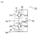
- FIG. 3 shows a transducer cell 20 employing a half-bridge configuration.
- the converter cell 20 of FIG. 3 includes a series body 23 in which a plurality (two in the illustrated case) of switches 21 and 22 are connected in series, and a DC capacitor that is connected in parallel to the series body 23 and smoothes a DC voltage. 29.
- Each of the switches 21 and 22 has a configuration in which semiconductor switching elements 21s and 22s (hereinafter simply referred to as switching elements) and diodes 21d and 22d are connected in antiparallel.
- switching elements 21 s and 22 s self-extinguishing type switching elements such as IGBTs (Insulated Gate Bipolar Transistors) and GCTs (Gate Commutated Turn-off Thyristors) are used.
- the converter cell 20 sets both terminals of the switching element 22s of the switch 22 to output terminals Po and No, and turns on and off the switching elements 21s and 22s to thereby output the output terminals Po and No. To output a positive voltage and a zero voltage of the DC capacitor 29.
- the converter cell 30 of FIG. 4 includes two series bodies 35 and 36 connected in parallel, and further includes a DC capacitor 39 that is connected in parallel to the series bodies 35 and 36 and smoothes a DC voltage.
- the series body 35 is configured by connecting in series a plurality (two in the illustrated example) of switching elements 31s and 32s to which diodes 31d and 32d are connected in antiparallel.
- the series body 36 is configured by connecting in series a switching element 34s in which either one is only the diode 33 and the other is a diode 34d connected in antiparallel.
- the switching elements 31 s, 32 s, and 34 s are composed of self-extinguishing switching elements such as IGBTs and GCTs, and switches 31, 32, and 34 configured by connecting diodes 31 d, 32 d, and 34 d in antiparallel, respectively. .
- the converter cell 30 includes an output terminal Po at the connection point between the switching elements 31 s and 32 s and the connection point between the diode 33 and the switching element 34 s as intermediate connection points between the series bodies 35 and 36. No, and switching elements 31s, 32s, and 34s are turned on and off, so that a positive voltage of the same polarity and a negative voltage of the opposite polarity are substantially equal to the magnitude of the voltage across the DC capacitor 39 from the output terminals Po and No. Is output. Moreover, the zero voltage of the state by which output terminal Po and No was short-circuited by the switching element is output.
- the converter cell 30 shown in FIG. 4 is referred to as a converter cell having a 1.5 bridge configuration.
- the converter cells 20, 30 are composed of a series body 23, 35, 36 of a plurality of switching elements or diodes and DC capacitors 29, 39 connected in parallel to the series body. , 39 is not limited to the configuration shown in FIGS. 3 and 4 as long as it selectively outputs the 39 voltages.
- converter cell 10 in phase arm 4U, 4V, 4W of power converter 1 will be further described.
- the converter cell 10 in the positive side arm 5U, 5V, 5W is shown in FIG. 4, the converter cell 20 capable of outputting the positive voltage and the zero voltage across the DC capacitor 29, as shown in FIG.
- the converter cell 30 that can output the positive voltage, the negative voltage, and the zero voltage across the DC capacitor 39 or both the converter cell 20 and the converter cell 30 is configured.
- the converter cell 10 in the negative side arm 6U, 6V, 6W is only the converter cell 30 that can output the positive voltage, the negative voltage, and the zero voltage across the DC capacitor 39 as shown in FIG. Consists of.
- all the converter cells 10 in the negative side arms 6U, 6V, 6W are constituted by the converter cells 30 capable of outputting a negative voltage, and the converter cells 10 in the positive side arms 5U, 5V, 5W are set to a positive voltage.
- a converter cell 20 capable of outputting zero voltage and a converter cell 30 capable of outputting negative voltage are combined.
- the converter cell 10 in the positive side arm 5U, 5V, 5W is configured by either the converter cell 20 or the converter cell 30.
- the converter cell 10 in the phase arms 4U, 4V, 4W is a converter cell 30 that can output a negative voltage only at least on one side arm (positive side arm 5U, 5V, 5W or negative side arm 6U, 6V, 6W). And all the converter cells 10 in the positive side arms 5U, 5V, 5W are constituted by the converter cells 30 capable of outputting a negative voltage, and the negative side arms 6U, 6V, 6W
- the converter cell 10 is configured by combining a converter cell 20 capable of outputting positive voltage and zero voltage and a converter cell 30 capable of outputting negative voltage.
- the converter cell 10 in the negative side arm 6U, 6V, 6W may be configured by either the converter cell 20 or the converter cell 30.
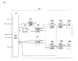
- FIG. 5 is a block diagram showing a configuration example of the control device 100 constituting the power conversion device according to Embodiment 1 of the present invention.
- the control device 100 includes a voltage command value generation unit and a PWM circuit that are configured by each control system.
- the voltage command value generation unit generates a DC voltage command value Kdc * based on the DC current Idc and DC voltage Vdc, and a normalization / calculation unit 110 that converts the detected current value / voltage value into a signal used for control.
- DC-AVR / DC-ACR control unit (DC constant voltage / DC constant current controller) 120 for controlling DC terminal voltage, and DC voltage command value Kdc * obtained by DC-AVR / DC-ACR control unit 120
- DC voltage command value calculation unit 140 for calculating DC voltage command values Vdc + * and Vdc ⁇ * of the positive side arm and the negative side arm based on the DC voltage adjustment amount ⁇ Vdc * and the DC short-circuit accident detection signal DCfault, and AC voltage AC voltage control unit 150 that controls AC voltage by calculating AC voltage command values Vac + * and Vac ⁇ * based on Vs, AC current Iac, and DC capacitor voltage Vcap; Based on the command values calculated by the DC voltage command value calculation unit 140 and the AC voltage control unit 150, the positive side and negative side arm voltage command value calculation units 160A and 160B that calculate the arm voltage command values V ++ and V ⁇ *.
- Vcell + * and Vcell- * of each converter cell based on the command values V ++ * and V ⁇ * calculated by the positive and negative arm voltage command value calculation units 160A and 160B.
- Cell individual control units 170A and 170B are provided.
- the voltage command generation unit is configured by 160A, the negative arm voltage command value calculation unit 160B, the positive cell individual control unit 170A, and the negative cell individual control unit 170B, and the voltage command value for the positive arm and the negative arm A voltage command value is generated.
- the PWM circuits 180A and 180B are configured so that, based on the positive side cell voltage command value Vcell + * and the negative side cell voltage command value Vcell- *, the positive side arm 5U, 5V, 5W, the negative side arm 6U, 6V, A gate signal for PWM control of the switching element of each converter cell 10 in 6 W is generated.
- the switching elements 21s, 22s, (31s, 32s, 34s) in each converter cell 10 are driven and controlled by the generated gate signal, and the output voltage of the power converter 1 is controlled to a desired value.
- a DC voltage command value calculation unit 140 that calculates DC voltage command values Vdc + * and Vdc ⁇ * of the positive side arm and the negative side arm at the time of a DC short-circuit accident, which is a main part of the present invention, will be described.
- the positive arm voltage command value V ++ output from the positive arm voltage command value calculation unit 160A and the negative arm voltage command value V- * output from the negative arm voltage command value calculation unit 160B will be described.
- the voltage command value V ++ for the positive arm is determined according to the DC voltage command value Vdc ++ output from the DC voltage command value calculation unit 140 and the AC voltage command value Vac ++ output from the AC voltage control unit 150, respectively.
- the negative arm voltage command value V- * is respectively applied to the DC voltage command value Vdc- * output from the DC voltage command value calculation unit 140 and the AC voltage command value Vac- * output from the AC voltage control unit 150. Will be decided accordingly. That is, the arm voltage command values V + * and V ⁇ * output from the positive and negative arm voltage command value calculation units 160A and 160B include two components, DC and AC.
- the converter cell 10 in the positive side arm 5U, 5V, 5W is composed of a converter cell 20 having a half bridge configuration capable of outputting a positive voltage and a zero voltage, and is supplied to the converter cell 10 of the positive side arm.
- the voltage command value is limited to a positive region. That is, the DC voltage command value Vdc ++ for the positive arm is limited to a positive value.
- the maximum amplitude of the AC voltage command value Vac ++ for the positive arm depends on the DC voltage command value Vdc ++.
- the converter cell 10 in the negative side arm 6U, 6V, 6W is composed of a converter cell 30 having a 1.5 bridge configuration capable of outputting positive voltage, negative voltage, and zero voltage.
- the voltage command value applied to the converter cell 10 of the negative arm can be in both positive and negative regions. That is, the DC voltage command value Vdc- * for the negative arm can be selected for both positive and negative.
- the negative arm AC voltage command value Vac- * is set to have a polarity opposite to that of the positive arm AC voltage command value Vac + *.
- the DC terminals P and N of the DC lines 2 and 3 have a configuration in which the positive side arm and the negative side arm are connected in series, the DC terminal P and N have the voltage command value V + * of the positive side arm and the negative side. A voltage substantially equal to the sum of the arm voltage command values V ⁇ * is output. Since the AC voltage command value Vac ++ for the positive arm and the AC voltage command value Vac- * for the negative arm are of opposite polarity, they cancel each other, and the DC terminals P and N have the DC voltage command value Vdc ++ for the positive arm A voltage substantially equal to the sum of the DC voltage command values Vdc- * of the negative arm is output.
- the DC voltage command value Kdc * obtained by the DC-AVR / DC-ACR control unit 120 is given to the DC voltage command value Vdc + * of the positive side arm, and the reverse of the DC voltage command value Vdc- * of the negative side arm.
- the DC voltage adjustment amount ⁇ Vdc * is output to the DC terminals P and N.
- the DC lines 2 and 3 are short-circuited, when the power converter 1 outputs the voltage of the above-mentioned DC voltage adjustment amount ⁇ Vdc * to the DC terminals P and N, the DC line is changed according to the DC line impedance. A direct current flows in 2 and 3.
- the DC voltage command value Kdc * When the DC voltage command value Kdc * is applied to the DC voltage command value Vdc + * of the positive arm and the DC voltage command value Kdc * of reverse polarity is applied to the DC voltage command value Vdc- * of the negative arm, the DC voltage command value If the magnitude of Kdc * is set to such a magnitude that the AC voltage command values Vac + * and Vac ⁇ * can be output, interconnection with the AC system is also possible.
- a current capable of detecting an accident can be caused to flow through the DC lines 2 and 3 while being connected to the AC system at the time of the accident. .
- an accident occurs, an arc voltage is generated at the DC terminals P and N. Therefore, a voltage opposite to the arc voltage is output, and after the DC terminal voltage is sufficiently low, the current that can detect the accident is applied to the DC lines 2 and 3. Shed.
- the DC voltage command value calculation unit 140 calculates the DC voltage command value Vdc + *, the DC voltage command value Kdc *, and the DC voltage of the positive arm from the DC voltage command value Kdc * obtained by the DC-AVR / DC-ACR control unit 120.
- the negative arm DC voltage command value Vdc- * is calculated from the adjustment amount ⁇ Vdc *.
- the DC voltage adjustment amount ⁇ Vdc * is equal to or higher than the voltage necessary for the current level at which the protection relay 93 operates to flow through the DC lines 2 and 3 and within the overcurrent level at which the power converter 1 stops. It is set to a preset value that is lower than the voltage.
- the DC voltage command value Vdc + * of the positive arm is configured to always give the DC voltage command value Kdc *.
- the DC voltage command value Vdc- * of the negative arm is DC short-circuited by switching the switch 142 based on a signal DCfault (normal time: 0, at time of accident: 1) given by a DC short-circuit fault detector (not shown).
- Different DC voltage command values are given depending on whether there is an accident.
- the DC voltage command value Vdc- * of the negative arm is given the DC voltage command value Kdc * when the steady state is “0”, and the DC voltage adjustment value and the DC voltage command value Kdc * are reversed when the accident is “1”.
- a value obtained by adding the amount ⁇ Vdc * to the adder 141 is given.
- the DC voltage command value Kdc * of the same component is added to the DC voltage command value Vdc + * of the positive arm and the DC voltage command value Vdc ⁇ * of the negative arm. Is given. That is, a command value that outputs a predetermined DC voltage to the DC terminals P and N is calculated.
- the DC short-circuit accident detection signal DCfault becomes “1”, the polarity of the DC voltage command value Kdc * is inverted, and the value of the DC voltage adjustment amount ⁇ Vdc * is added.
- the DC voltage adjustment amount ⁇ Vdc * is added to the DC voltage command value Kdc * and given as the DC voltage command value Vdc ⁇ * of the negative arm. If so, the DC voltage adjustment amount ⁇ Vdc * may be added to the DC voltage command value Kdc * and given as the DC voltage command value Vdc + * of the positive arm.
- all the converter cells 10 in the negative side arms 6U, 6V, 6W are constituted by the converter cells 30 capable of outputting a negative voltage, and the positive side arms 5U, 5V,
- the converter cell 10 within 5 W is composed of a converter cell 20 capable of outputting positive voltage and zero voltage.
- the DC voltage command value calculation unit 140 that calculates the DC voltage command values Vdc + * and Vdc ⁇ * of the positive side arm and the negative side arm is in a steady state at the AC end of the power converter 1 when a DC short circuit accident occurs.
- the same AC voltage is output, and a predetermined voltage at which a current level at which the protective relay 93 can detect an accident flows can be output to the DC terminal of the power converter 1.
- the protection relay 93 on the DC lines 2 and 3 can be operated to detect and remove the fault point. Become.
- the converter cell 10 is gate-blocked in the event of a DC short-circuit fault, so that the sum of the capacitor voltages of the converter cell 30 is output to the DC terminal of the power converter 1 and the fault current is suppressed.
- the ratio of the converter cells 30 in the phase arm the voltage output to the DC terminal of the power converter 1 increases, and the accident current suppression effect increases.
- the fault current suppression effect is increased, and the converter cell 10 in the positive arm is replaced by the converter cell 30 or both the converter cell 20 and the converter cell 30.
- the AC voltage of the power converter 1 is output to the AC terminal as in the normal state, It is possible to output a current at which the protective relay 93 can determine an accident to the DC terminal.
- FIG. 7 is a circuit diagram of converter cell 40 employing a full bridge configuration used as a converter cell of the power conversion device according to Embodiment 2 of the present invention.
- the converter cell 10 in the positive side arm 5U, 5V, 5W of the power converter 1 shown in FIG. 2 is used as the converter cell 20 having a half-bridge configuration, and the negative side arm 6U, 6V.
- the converter cell 10 in 6W is configured by a converter cell 40 of a full bridge cell, and the other configurations are the same as those of the first embodiment, and thus the description thereof is omitted.
- Each of the series bodies 45 and 46 is configured by connecting in series a plurality (two in the illustrated example) of switching elements 41s, 42s, 43s, and 44s to which diodes 41d, 42d, 43d, and 44d are connected in antiparallel.
- the switching elements 41 s, 42 s, 43 s, and 44 s are composed of self-extinguishing switching elements such as IGBTs and GCTs, and switches 41, 42, 43 and 44 are used.
- the converter cell 40 has terminals of the connection points of the switching elements 41 s and 42 s and the connection points of the switching elements 43 s and 44 s as intermediate connection points of the series bodies 45 and 46 at the output terminals.
- the converter cell 40 is composed of a series body of a plurality of switching elements or diodes and a DC capacitor connected in parallel to the series body, and is configured to selectively output the voltage of the DC capacitor by a switching operation.
- the configuration is not limited to that shown in FIG.
- the converter cell 10 in the positive side arm 5U, 5V, 5W is constituted by a converter cell 20 capable of outputting the positive voltage and zero voltage across the DC capacitor 29 as shown in FIG.
- the converter cell 10 in the negative side arm 6U, 6V, 6W is a converter cell 40 capable of outputting positive voltage, negative voltage and zero voltage across the DC capacitor 49 as shown in FIG. Constitute.
- the converter cell 10 in the positive arm operates so as to output a positive DC voltage and an AC voltage linked to the AC system in the event of a DC short-circuit accident, and the converter in the negative arm
- the cell 10 operates to output a negative DC voltage and an AC voltage having a polarity opposite to that of the positive arm.
- the power converter 1 when a DC short-circuit accident occurs, the power converter 1 operates to output an AC voltage similar to that in a steady state to the AC terminal, and the protection relay 93 can determine the accident at the DC terminal of the power converter 1. It is possible to output a voltage capable of flowing a large current.
- the converter cell 10 in the positive arm is configured to include the converter cell 40 or both the converter cell 20 and the converter cell 40 so that the fault current suppression effect is increased, and the converter in the negative arm is configured. Even in the main circuit configuration in which the cell 10 is composed only of the converter cell 40, the AC voltage of the power converter 1 is output to the AC terminal as in the normal state, and the protection relay 93 is provided at the DC terminal of the power converter 1. It is possible to output a voltage that can flow an accident-identifiable current.
- the converter cell 10 in the phase arm 4U, 4V, 4W is a converter cell 40 that can output a negative voltage only at least one arm (positive arm 5U, 5V, 5W or negative arm 6U, 6V, 6W).
- the converter cells 10 in the positive side arms 5U, 5V, and 5W are configured by the converter cells 40 that can output a negative voltage, and the negative side arms 6U, 6V, and 6W
- the converter cell 10 may be composed of a converter cell 20 capable of outputting positive voltage and zero voltage.
- FIG. 8 is a block diagram showing a configuration of control apparatus 100 in the power conversion apparatus according to Embodiment 3 of the present invention. 8 is the same as control device 100 in Embodiment 1 shown in FIG. 5 except that a DC voltage adjustment amount calculation unit 130 for calculating DC voltage adjustment amount ⁇ Vdc * based on DC current Idc is provided. Or, the same reference numerals are given to the corresponding parts, and the description is omitted.
- FIG. 9 shows the configuration of the DC voltage adjustment amount calculation unit 130 of the power conversion apparatus according to the third embodiment, which includes a subtracter 131 and a controller 132.
- the DC voltage adjustment amount calculation unit 130 causes a DC current command to flow a current within a current level at which the power converter 1 stops protection when the protection relay 93 on the DC lines 2 and 3 operates at a current level or higher.
- the controller 132 By controlling the controller 132 so that the difference between the value Idc * and the DC current Idc approaches zero, the DC voltage adjustment amount ⁇ Vdc * is given.
- the DC current command value Idc * is a DC component, an AC component, or an AC component if the current is equal to or higher than the current level at which the protection relay 93 on the DC lines 2 and 3 operates and within the current level at which the power converter 1 stops protection. Either one of two components of a direct current component and an alternating current component may be given. Further, a triangular wave or the like may be used instead of the AC component.
- the direct current voltage adjustment amount ⁇ Vdc * is a direct current component
- a current based on the impedance value of the resistance component of the direct current lines 2 and 3 can be passed through the direct current lines 2 and 3.
- a current based on the impedance values of the reactor components 2 and 3 can be passed through the DC lines 2 and 3, and the protection relay 93 can be operated.
- the power converter 1 outputs a voltage corresponding to the DC voltage adjustment amount ⁇ Vdc * to the DC terminal 2 and 3 at the time of a DC short-circuit accident, so that a DC current flows through the DC lines 2 and 3.
- the DC current Idc rises until an accident is detected by the protective relay 93 on the DC lines 2 and 3, and when an accident is detected, the DC circuit breaker 92 that sandwiches the accident point on the DC lines 2 and 3 opens, and the accident point is determined. Remove.
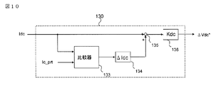
- FIG. 10 shows a configuration of DC voltage adjustment amount calculation unit 130 used in control device 100 in the power conversion device according to Embodiment 4 of the present invention.
- the configuration of the control device 100 in the power conversion device according to the fourth embodiment is the same as that in FIG. 8, and the DC voltage adjustment amount calculation unit 130 used therein has a comparator 133, a current adjustment, as shown in FIG. And a voltage command value converter 136.
- the voltage command value converter 136 calculates a DC voltage adjustment amount ⁇ Vdc * based on the magnitude of the DC current Idc, and a DC voltage that causes a current within a current level at which the power converter 1 stops protection to flow. An adjustment amount ⁇ Vdc * is given.
- the DC voltage adjustment amount calculation unit 130 shown in FIG. 10 first determines whether the magnitude of the DC current Idc is smaller than the value Ic_prt set to be equal to or lower than the protection current level of the power converter 1 by the comparator 133. If it is smaller, the comparator 133 outputs “1”, the current regulator 134 multiplies the current increase amount ⁇ Idc, and the adder 135 adds it to the DC current Idc. The voltage command value converter 136 multiplies the output of the adder 135 by the voltage command value conversion gain Kdc to calculate the DC voltage adjustment amount ⁇ Vdc *.
- the power converter 1 outputs a voltage corresponding to the DC voltage adjustment amount ⁇ Vdc * in the event of a DC short-circuit accident, thereby causing a DC component current Idc to flow through the DC lines 2 and 3.
- the DC current Idc rises until an accident is detected by the protective relay 93 on the DC lines 2 and 3, and when an accident is detected, the DC circuit breaker 92 that sandwiches the accident point on the DC lines 2 and 3 opens. Remove.
- FIG. 11 is a diagram showing a configuration of DC voltage adjustment amount calculation unit 130 used in control device 100 in the power conversion device according to Embodiment 5 of the present invention.
- the configuration of the control device 100 in the power conversion device according to the fifth embodiment is the same as that in FIG. 8, and the DC voltage adjustment amount calculation unit 130 used there is a comparator 133, a current adjustment, as shown in FIG. And a voltage command value converter 136, a maximum value holding circuit 137, a counter 138 and a multiplier 139.
- the DC voltage adjustment amount calculation unit 130 first holds the maximum value of the DC current Idc by the maximum value holding circuit 137.
- the comparator 133 determines whether the maximum value of the direct current is smaller than a value Ic_prt set to be equal to or lower than the protection current level of the power converter 1. When it is small, the comparator 133 outputs “1”, and when it is large, it outputs “0”.
- the counter 138 counts up every calculation cycle when “1” is input, and stops counting up when “0” is input.
- the output of the counter 138 is multiplied by the current amplification amount ⁇ Idc by the current regulator 134, and is multiplied by, for example, a sine wave having a frequency twice the frequency of the AC power supply 9 by the multiplier 139.
- the value to be multiplied may be a sine wave of another frequency component or a triangular wave.
- the voltage command value converter 136 multiplies the output of the multiplier 139 by the voltage command value conversion gain Kdc to calculate the DC voltage adjustment amount ⁇ Vdc *. That is, a DC voltage adjustment amount ⁇ Vdc * is applied to the DC lines 2 and 3 so that an AC component current that allows the protection relay 93 to operate is supplied.
- the power converter 1 outputs a voltage corresponding to the DC voltage adjustment amount ⁇ Vdc * in the event of a DC short-circuit accident, thereby causing a current such as an AC component to flow through the DC lines 2 and 3.
- the DC current Idc rises until an accident is detected by the protective relay 93 on the DC lines 2 and 3, and when an accident is detected, the DC circuit breaker 92 that sandwiches the accident point on the DC lines 2 and 3 opens, and the accident point is determined. Remove.
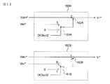
- FIG. 12 is a diagram showing a configuration of positive side and negative side arm voltage command value calculation units 160A and 160B used in control device 100 in the power conversion device according to Embodiment 6 of the present invention.
- the configuration of control device 100 in the power conversion device according to the sixth embodiment is the same as that in FIG. 5 or FIG.
- the positive arm voltage command value calculation unit 160A and the negative arm voltage command value calculation unit 160B include DC voltage command values Vdc + * and Vdc ⁇ *, an AC voltage command value Vac *, and presence / absence of AC interconnection. Based on the signal DCfault2, the positive arm voltage command value V + * and the negative arm voltage command value V- * are calculated.
- the AC output switches 161A and 161B are switched based on a signal DCfault2 (interconnection: 0, non-interconnection: 1) indicating whether or not AC interconnection is present.
- DCfault2 interconnection: 0, non-interconnection: 1
- the AC voltage command value Vac * is given to the arm DC voltage command values Vdc + * and Vdc ⁇ *
- the AC connection is “1”
- the arm DC voltage command values Vdc + * and Vdc ⁇ are supplied.
- the AC voltage command value Vac * is given as zero.
- a current is passed through the DC lines 2 and 3 using only energy stored in the DC capacitor 29 (39, 49) in the converter cell 10.
- the DC current Idc rises until an accident is detected by the protective relay 93 on the DC lines 2 and 3, and when an accident is detected, the DC circuit breaker 92 that sandwiches the accident point on the DC lines 2 and 3 opens, and the accident point is determined. Remove.
- the configuration of the converter cell 10 in the phase arm 4U, 4V, 4W of the power converter 1 includes a positive side arm 5U, 5V, 5W and a negative side arm 6U, 6V, 6W, a converter cell 20 and a converter cell.
- the configuration in which both 40 are connected in series, the configuration in any of Embodiments 1 and 2, may be used.
- FIG. 13 is a schematic configuration diagram of a three-terminal HVDC system using a power conversion device according to Embodiment 7 of the present invention.
- the power converters 1A, 1B, and 1C connected to the AC systems 9A, 9B, and 9C constitute a three-terminal HVDC system by connecting the DC terminals with DC lines 2 and 3, respectively. ing.
- FIG. 14 is a flowchart illustrating an accident point removal operation using the power conversion device and the protection relay according to the seventh embodiment of the present invention. With reference to FIG. 13 and FIG. 14, description will be given of DC accident removal when the DC lines 2 and 3 are short-circuited in the three-terminal HVDC system.
- each power converter 1A, 1B, 1C has a preset protection level (current value) of the power converter. Etc.) is detected (S2), and all the switching elements in the power converters 1A, 1B, 1C are turned off (S3). By turning off the switching element, it is possible to suppress the accident current flowing in each of the power conversion devices 1A, 1B, and 1C.
- each of the power conversion devices 1A, 1B, and 1C outputs a voltage that can be detected by a protective relay (not shown) at the DC end and that can be output by each of the power converters 1A, 1B, and 1C (S4).
- the impedances of the DC lines 2 and 3 increase, so that the power converters 1A, 1B, and 1C determine, for example, that the DC line accident is removed based on the fact that a predetermined current does not flow.
- the power converters 1A, 1B, and 1C cut off from the DC lines 2 and 3 can operate as STATCOM that supplies reactive power to the AC systems 9A, 9B, and 9C (S6).
- FIG. 15 is a schematic configuration diagram of a three-terminal HVDC system including a DC short-circuit fault point determination unit according to Embodiment 8 of the present invention.
- the open / close states of the circuit breaker groups 92A, 92A ′, 92B, 92B ′, 92C, 92C ′ on the DC line are given to the DC short-circuit fault point determination unit 200.
- the DC short-circuit fault point determination unit 200 determines a DC short-circuit fault point based on the switching state of the DC circuit breaker, and gives a command to operate each switch to remove the fault point.
- FIG. 16 is a flowchart illustrating an operation for removing the accident point using the power conversion device and the protection relay according to the eighth embodiment of the present invention.
- DC accident elimination and sound power transmission between two terminals when the DC lines 2 and 3 are short-circuited in the three-terminal HVDC system will be described.
- a DC short-circuit accident occurs at the closest end of the power converter 1A
- each power converter 1A, 1B, 1C detects that a preset protection level (such as a current value) of the power converter is exceeded (S12), and each power converter All switching elements in 1A, 1B and 1C are turned OFF (S13).
- a preset protection level such as a current value
- the power converter 1A outputs a voltage at which the protective relay (not shown) can detect an accident and can be output by the power converter 1A at the DC terminal (S14), so that the sensor 91A detects the accident and the circuit breaker 92A is opened (S15). Since the fault point is between the sensors 91A and 91A ′, when the converter 1A outputs a voltage to the DC terminal, a current flows through the sensor 91A, the circuit breaker 92A, and the fault point. This current is detected by the sensor 91A, and only the circuit breaker 92A is opened by operating the protective relay.
- each power converter 1A, 1B, 1C detects that a preset protection level (such as a current value) of the power converter is exceeded (S12), and each power converter All switching elements in 1A, 1B and 1C are turned OFF (S13). By turning off the switching element, it is possible to suppress the accident current flowing in each of the power conversion devices 1A, 1B, and 1C.
- a preset protection level such as a current value
- the power converter 1A outputs a voltage at which a protection relay (not shown) can detect an accident and can be output by the power converter 1A (S14), and sensors 91A, 91A ′, 91B ′ (91A) 91A ′, 91C ′) detects an accident and opens the circuit breakers 92A, 92A ′, 92B ′ (92A, 92A ′, 92C ′) (S15).
- the converter 1A Since the accident point is between the sensors 91B and 91B ′ (91C and 91C ′), the converter 1A outputs a voltage to the DC terminal, whereby the sensors 91A, 91A ′, 91B ′ (91A, 91A ′, 91C ′) are output. ), Current flows through the circuit breakers 92A, 92A ′, 92B ′ (92A, 92A ′, 92C ′) and the fault point.
- This current is detected by the sensors 91A, 91A ′, 91B ′ (91A, 91A ′, 91C ′), and the breaker 92A, 92A ′, 92B ′ (92A, 92A ′, 92C ′) is activated by the operation of the protective relay. Open. However, since the accident point is between the sensors 91B and 91B ′, power transmission between the sound terminals (power converters 1A and 1C (1B)) cannot be performed as it is.
- a signal indicating that the circuit breakers 92A, 92A ′, 92B ′ (92A, 92A ′, 92C ′) are opened is given to the DC short-circuit fault point determination unit 200 (S16), and there are a plurality of opened circuit breakers. (S17), among the opened circuit breakers, the circuit breaker 92B '(92C') farthest away from the converter and the circuit breaker 92B (93C) one distant from the converter are opened, and another circuit breaker 92A is opened. , 92A ′, 92C, 92C ′ (92A, 92A ′, 92B, 92B ′) are provided (S18 ′).
- the power converter 1A cut off from the DC lines 2 and 3 can also operate as STATCOM for supplying reactive power to the AC system 9A (S19).
- STATCOM reactive power to the AC system 9A
- the number of DC terminals may be four or more, and the number of DC line terminals and the connection method are not limited.
- the circuit breaker is opened and closed by the output of one power conversion device and the communication to the DC short-circuit fault point determination unit, but to the output of a plurality of power conversion devices and the DC short-circuit fault point determination unit The communication may not be used.
- 1, 1A, 1B, 1C power converter
- 2 positive DC line
- 3 negative DC line
- 4U, 4V, 4W phase arm
- 5U, 5V, 5W positive arm
- 6U, 6V, 6W Negative arm
- 7U, 7V, 7W AC connection point
- 8 Transformer
- 9 AC power supply
- 10, 20, 30, 40 Converter cell, 21, 22, 31, 32, 34, 41, 42 , 43, 44: switch, 21s, 22s, 31s, 32s, 34s, 41s, 42s, 43s, 44s: switching element, 21d, 22d, 31d, 32d, 34d, 41d, 42d, 43d, 44d: diode, 23, 35, 36, 45, 46: Series body, 29, 39, 49: DC capacitor
- 90 DC short-circuit accident
- 91 Sensor
- 92 DC circuit breaker
- 93 Protection relay 100: control device, 110 to 170: voltage command generation unit (110: standardization / calculation unit, 120: DC-AVR, DC-ACR
Abstract
Description
そこで、高圧用途に適した多重変圧器を必要としない電力変換装置として、複数の変換器の出力をカスケード接続したマルチレベル変換器が提案されており、その中の一つにモジュラーマルチレベル変換器がある。 There are various methods for multiplexing converters, including reactor multiplexing, transformer multiplexing, and direct multiplexing. When multiplexed by a transformer, the AC side is insulated by the transformer, so that there is an advantage that the DC of each converter can be shared. However, when the output voltage is high, the configuration of the multiple transformer becomes complicated and the cost of the transformer increases.
Therefore, as a power converter that does not require multiple transformers suitable for high-voltage applications, multi-level converters in which the outputs of a plurality of converters are cascade-connected have been proposed, one of which is a modular multi-level converter. There is.
三相MMCの場合は、各相個別にアームを構成し、カスケード接続されている変換器セル総数の半分の変換器セルの出力端を交流端子、各相アームの両端は互いに接続され、それぞれの端子を直流端子としており、各相アームは正側アーム、負側アームの2つのアームより構成される。MMC変換器の各変換器セル出力は、MMC変換器の交流端および直流端子の両側に接続されているため、各変換器セルは、直流および交流の両方を出力するという特徴を持つ。 A modular multilevel converter (hereinafter referred to as MMC) is composed of an arm in which a plurality of unit converters (hereinafter referred to as converter cells) called cells are cascade-connected. The converter cell includes a plurality of semiconductor switches and a DC capacitor, and outputs a voltage across the DC capacitor and a zero voltage by turning on and off the semiconductor switch.
In the case of a three-phase MMC, each phase is individually configured with an arm, and the output terminals of the converter cells that are half of the total number of cascade-connected converter cells are connected to the AC terminal, and both ends of each phase arm are connected to each other. The terminal is a DC terminal, and each phase arm is composed of two arms, a positive arm and a negative arm. Since each converter cell output of the MMC converter is connected to both sides of the AC terminal and the DC terminal of the MMC converter, each converter cell has a feature of outputting both DC and AC.
また、直流線路での事故は、線路上の保護リレーにより、事故の検知および除去を行っているが、上記保護リレーは半導体スイッチング素子の動作に比べ遅いという問題がある。つまり、変換器により事故電流の抑制を行った場合、保護リレーが動作する前に事故を検知する情報である直流電流が遮断され、事故点の検知および除去が行えないという問題が生じる。 Conventionally, an accident current is suppressed by outputting a voltage opposite to the gate block or the arc voltage at the time of a high-voltage DC line fault using an MMC converter including a converter cell having a full-bridge configuration. In the above method, since the accident current is suppressed at high speed by controlling the semiconductor switching element in the converter cell, the output of the DC terminal becomes zero in a short time, and the accident can be eliminated.
In addition, accidents on the DC line are detected and removed by a protective relay on the line, but there is a problem that the protective relay is slower than the operation of the semiconductor switching element. That is, when the fault current is suppressed by the converter, the DC current that is information for detecting the fault is interrupted before the protective relay operates, and there is a problem that the fault point cannot be detected and removed.
前記複数相に対応する複数の正側アームおよび前記複数の負側アームのそれぞれは、互いに直列接続された複数のスイッチング素子の直列体と、この直列体に並列接続された直流コンデンサから成る変換器セルを、1つあるいは複数直列接続して構成され、
前記制御装置は、前記正側アームに対する第1の電圧指令値と前記負側アームに対する第2の電圧指令値を生成する電圧指令生成部を有して、前記正側アームおよび負側アーム内の前記変換器セルのスイッチング素子を制御し、前記直流線路における直流短絡事故を検知した場合に、前記電力変換器の直流端子から前記直流線路内の保護リレーを動作させることが可能な所定の直流電圧を出力させるものである。 The power conversion device according to the present invention is connected between a plurality of phases of AC lines and a DC line, a positive arm and a negative arm corresponding to each phase of the plurality of phases are connected in series, and the plurality of positive electrodes are connected. One end of the side arm is connected to one another and connected to the positive DC line, and one end of the plurality of negative side arms is connected to one another and connected to the negative DC line, and power is supplied between AC and DC. In a power converter that includes a power converter that performs conversion and a control device that controls the power converter,
Each of the plurality of positive-side arms and the plurality of negative-side arms corresponding to the plurality of phases includes a series body of a plurality of switching elements connected in series to each other, and a converter including a DC capacitor connected in parallel to the series body One or more cells connected in series,
The control device includes a voltage command generation unit that generates a first voltage command value for the positive arm and a second voltage command value for the negative arm, and includes a voltage command generator in the positive arm and the negative arm. A predetermined DC voltage capable of operating the protective relay in the DC line from the DC terminal of the power converter when the switching element of the converter cell is controlled and a DC short-circuit accident in the DC line is detected. Is output.
以下、この発明の実施の形態1に係る電力変換装置を図1から図6に基づいて詳細に説明する。図1は、この発明の実施の形態1による電力変換装置を使用した2端子HVDC(High-Voltage DC Transmission)システムの概略構成図である。
図1に示すように、交流系統9A、9Bと接続された電力変換器1A、1Bは、それぞれの直流端子を直流線路2、3で接続することで2端子HVDCシステムを構成している。この構成において、直流線路2、3内は、センサ群91A、91B、直流遮断器群92A、92Bおよび保護リレー93A、93Bを備える。直流線路2、3において直流短絡事故90が発生した場合、直流端子に流れる事故電流をセンサ群91A、91Bにより検知し、保護リレー93A、93Bが事故判別を行い、直流遮断器群92A、92Bを開放する。
Hereinafter, a power converter according to
As shown in FIG. 1, the
電力変換器1の各相は、正側アーム5U、5V、5Wと負側アーム6U、6V、6Wのそれぞれが直列接続され、その接続点である交流端7U、7V、7Wが各相交流線に接続される相アーム4U、4V、4Wで構成されている。図2においては、交流端7U、7V、7Wは各相交流線に直接接続されているが、3巻線トランスを介して各相交流線に接続してもよい。
3つの相アーム4U、4V、4Wの内、正側アーム5U、5V、5Wの一端(交流端7U、7V、7Wの反対側)は互いに接続されて正の直流線路2に、負側アーム6U、6V、6Wの一端は互いに接続されて負の直流線路3に接続され、3つの相アーム4U、4V、4Wが正負の直流線路2、3間に並列接続されるような構成になっている。 FIG. 2 is a schematic configuration diagram of the power conversion device according to
Each phase of the
Of the three phase arms 4U, 4V, and 4W, one ends of the positive side arms 5U, 5V, and 5W (opposite sides of the AC ends 7U, 7V, and 7W) are connected to each other to connect the positive DC line 2 to the negative side arm 6U. , 6V, 6W are connected to each other and connected to the
なお、アームリアクトル11U、11V、11Wが挿入される位置は、各アーム内のいずれの位置でもよく、正負に分けて複数個の構成であってもよい。
また、制御装置100は、電圧指令値生成部とPWM回路を備えてゲート信号を生成し、各相の正側アーム5U、5V、5Wと負側アーム6U、6V、6W内の各変換器セル10を制御する。なお、制御装置100の構成の詳細は後述する図5で説明する。 Each of the positive side arms 5U, 5V, and 5W of the phase arms 4U, 4V, and 4W and the negative side arms 6U, 6V, and 6W includes a cell group in which one or a plurality of converter cells 10 are connected in series. 11U, 11V, and 11W are connected in series.
Note that the positions where the arm reactors 11U, 11V, and 11W are inserted may be any positions in each arm, and may have a plurality of configurations divided into positive and negative.
Further, the
なお、各相の交流電流Iacおよび直流電流Idc(図5参照)は、図示しない電流検出器により検出してもよく、各相の正側アーム5U、5V、5W、負側アーム6U、6V、6Wにそれぞれ流れる正側アーム電流ipu、ipv、ipw、負側アーム電流inu、inv、inwから演算して用いてもよい。 Positive arm currents ipu, ipv, ipw and negative arm currents inu, inv, inw flowing in the positive side arms 5U, 5V, 5W and negative side arms 6U, 6V, 6W of the respective phases are current detectors not shown, respectively. Is input to the
The AC current Iac and DC current Idc (see FIG. 5) of each phase may be detected by a current detector (not shown), and the positive side arm 5U, 5V, 5W, the negative side arm 6U, 6V of each phase, You may calculate and use from the positive side arm current ipu, ipv, ipw, and the negative side arm current inu, inv, inw which flow in 6W, respectively.
図3の変換器セル20は、複数(図示の場合は2個)のスイッチ21、22が直列に接続された直列体23と、この直列体23に並列接続され直流電圧を平滑化する直流コンデンサ29とから構成される。それぞれのスイッチ21、22は、半導体スイッチング素子21s、22s(以下、単にスイッチング素子と称す)とダイオード21d、22dが逆並列に接続された構成となっている。
スイッチング素子21s、22sは、IGBT(Insulated Gate Bipolar Transistor)やGCT(Gate Commutated Turn-off thyristor)等の自己消弧形のスイッチング素子が用いられる。 The configuration of the converter cells 10 provided in the positive side arms 5U, 5V, 5W and the negative side arms 6U, 6V, 6W will be described with reference to FIG. FIG. 3 shows a
The
As the
図4の変換器セル30は、2つの直列体35、36を並列接続し、さらに直列体35、36に並列接続され直流電圧を平滑化する直流コンデンサ39を備えて構成される。直列体35は、それぞれダイオード31d、32dが逆並列に接続された複数(図示の場合は2個)のスイッチング素子31s、32sを直列接続して構成される。また、直列体36は、どちらか一方はダイオード33のみで、他方はダイオード34dが逆並列に接続されたスイッチング素子34sを直列接続して構成される。スイッチング素子31s、32s、34sは、IGBTやGCT等の自己消弧形のスイッチング素子から成り、それぞれダイオード31d、32d、34dが逆並列に接続されて構成されるスイッチ31、32、34が用いられる。 A configuration of another example of the converter cell 10 will be described with reference to FIG.
The
正側アーム5U、5V、5W内の変換器セル10は、図3に示すように直流コンデンサ29両端の正電圧および零電圧を出力することが可能である変換器セル20、または図4に示すように直流コンデンサ39両端の正電圧、負電圧および零電圧を出力することが可能である変換器セル30、または変換器セル20と変換器セル30の両方を含むように構成する。
一方、負側アーム6U、6V、6W内の変換器セル10は、図4に示すように直流コンデンサ39両端の正電圧、負電圧および零電圧を出力することが可能である変換器セル30のみで構成する。 Next, the configuration of converter cell 10 in phase arm 4U, 4V, 4W of
The converter cell 10 in the positive side arm 5U, 5V, 5W is shown in FIG. 4, the
On the other hand, the converter cell 10 in the negative side arm 6U, 6V, 6W is only the
制御装置100は、上述したように各制御系から成る電圧指令値生成部とPWM回路とを備える。電圧指令値生成部は、検出した電流値・電圧値を制御で用いる信号に変換する規格化/演算部110と、直流電流Idcと直流電圧Vdcに基づいて直流電圧指令値Kdc*を生成して直流端子電圧を制御するDC-AVR・DC-ACR制御部(直流定電圧・直流定電流制御器)120と、DC-AVR・DC-ACR制御部120で得られた直流電圧指令値Kdc*と直流電圧調整量△Vdc*および直流短絡事故検出信号DCfaultに基づいて、正側アーム・負側アームの直流電圧指令値Vdc+*、Vdc-*を演算する直流電圧指令値演算部140と、交流電圧Vsと交流電流Iacおよび直流コンデンサ電圧Vcapに基づいて交流電圧指令値Vac+*、Vac-*を演算して交流電圧を制御する交流電圧制御部150と、直流電圧指令値演算部140と交流電圧制御部150より演算された指令値に基づいて、アーム電圧指令値V+*、V-*を演算する正側及び負側アーム電圧指令値演算部160A、160Bと、正側及び負側アーム電圧指令値演算部160A、160Bにより演算された指令値V+*、V-*に基づいて、各変換器セルの電圧指令値Vcell+*、Vcell-*を出力する各セル個別制御部170A、170Bを備えている。
なお、規格化/演算部110、 DC-AVR、DC-ACR制御部120、直流電圧調整量演算部130、直流電圧指令値演算部140、交流電圧制御部150、正側アーム電圧指令値演算部160A、負側アーム電圧指令値演算部160B、正側各セル個別制御部170A、負側各セル個別制御部170Bにより電圧指令生成部が構成され、正側アームに対する電圧指令値と負側アームに対する電圧指令値が生成される。 FIG. 5 is a block diagram showing a configuration example of the
As described above, the
Standardization /
はじめに、正側アーム電圧指令値演算部160Aから出力される正側アームの電圧指令値V+*と負側アーム電圧指令値演算部160Bから出力される負側アームの電圧指令値V-*について述べる。正側アームの電圧指令値V+*は、直流電圧指令値演算部140から出力される直流電圧指令値Vdc+*と交流電圧制御部150から出力される交流電圧指令値Vac+*それぞれに応じて決定され、負側アームの電圧指令値V-*は、直流電圧指令値演算部140から出力される直流電圧指令値Vdc-*と交流電圧制御部150から出力される交流電圧指令値Vac-*それぞれに応じて決定される。つまり、正側及び負側アーム電圧指令値演算部160A、160Bから出力されるアーム電圧指令値V+*、V-*は、直流と交流の2つの成分を含む。 Hereinafter, a DC voltage command
First, the positive arm voltage command value V ++ output from the positive arm voltage command
一方、負側アーム6U、6V、6W内の変換器セル10は、正電圧、負電圧および零電圧の出力が可能である1.5ブリッジ構成の変換器セル30で構成されており、変換器セル内を流れる電流に依存するが、負側アームの変換器セル10に与える電圧指令値は正負の領域ともに可能である。つまり、負側アームの直流電圧指令値Vdc-*は正負ともに選択可能である。また、負側アームの交流電圧指令値Vac-*は正側アームの交流電圧指令値Vac+*の逆極性となる様に設定する。 The converter cell 10 in the positive side arm 5U, 5V, 5W is composed of a
On the other hand, the converter cell 10 in the negative side arm 6U, 6V, 6W is composed of a
以上のように、負側アームの直流電圧指令値Vdc-*を操作することで、事故時において交流系統と連系した状態で、事故検知可能な電流を直流線路2、3に流すことが出来る。なお、事故発生時では直流端子P、Nにアーク電圧が発生するため、アーク電圧に対向する電圧を出力し、直流端子電圧が十分低くなってから、事故検知可能な電流を直流線路2、3に流す。 When the DC voltage command value Kdc * is applied to the DC voltage command value Vdc + * of the positive arm and the DC voltage command value Kdc * of reverse polarity is applied to the DC voltage command value Vdc- * of the negative arm, the DC voltage command value If the magnitude of Kdc * is set to such a magnitude that the AC voltage command values Vac + * and Vac− * can be output, interconnection with the AC system is also possible.
As described above, by operating the DC voltage command value Vdc- * of the negative arm, a current capable of detecting an accident can be caused to flow through the
一方、直流短絡事故時では、直流短絡事故検出信号DCfaultが「1」となり、直流電圧指令値Kdc*の極性が反転し、直流電圧調整量△Vdc*の値を加算するため、正側アームの直流電圧指令値Vdc+*と負側アームの直流電圧指令値Vdc-*で異なる直流電圧指令値が与えられる。つまり、直流端子P、Nに直流電圧調整量△Vdc*を出力するような指令値を演算する。 Since the DC short-circuit accident detection signal DCfault is “0” in the normal state, the DC voltage command value Kdc * of the same component is added to the DC voltage command value Vdc + * of the positive arm and the DC voltage command value Vdc− * of the negative arm. Is given. That is, a command value that outputs a predetermined DC voltage to the DC terminals P and N is calculated.
On the other hand, in the case of a DC short-circuit accident, the DC short-circuit accident detection signal DCfault becomes “1”, the polarity of the DC voltage command value Kdc * is inverted, and the value of the DC voltage adjustment amount ΔVdc * is added. Different DC voltage command values are given by the DC voltage command value Vdc + * and the negative arm DC voltage command value Vdc- *. That is, a command value that outputs the DC voltage adjustment amount ΔVdc * to the DC terminals P and N is calculated.
相アーム内の変換器セル30の割合を増やすことで事故電流抑制効果を増加させた、正側アーム内の変換器セル10を変換器セル30または変換器セル20と変換器セル30の両方を含むように構成し、負側アーム内の変換器セル10を変換器セル30のみで構成した主回路構成においても、電力変換器1の交流端には定常時と同様の交流電圧を出力し、直流端には保護リレー93が事故判別可能な電流を出力することが可能である。 In the case of the main circuit configuration described above, the converter cell 10 is gate-blocked in the event of a DC short-circuit fault, so that the sum of the capacitor voltages of the
By increasing the ratio of the
次に、この発明の実施の形態2に係る電力変換装置を図7に基づいて詳細に説明する。図7は、この発明の実施の形態2による電力変換装置の変換器セルとして使用するフルブリッジ構成を採用した変換器セル40の回路図である。
実施の形態2の電力変換装置は、図2に示す電力変換器1の正側アーム5U、5V、5W内の変換器セル10をハーフブリッジ構成の変換器セル20とし、負側アーム6U、6V、6W内の変換器セル10をフルブリッジセルの変換器セル40で構成したものであり、他の構成は、先の実施の形態1の場合と同一であるので、その説明は省略する。 Embodiment 2. FIG.
Next, a power converter according to Embodiment 2 of the present invention will be described in detail with reference to FIG. FIG. 7 is a circuit diagram of
In the power conversion device of the second embodiment, the converter cell 10 in the positive side arm 5U, 5V, 5W of the
なお、変換器セル40は、複数のスイッチング素子またはダイオードの直列体と、この直列体に並列に接続された直流コンデンサとから成り、スイッチング動作により直流コンデンサの電圧を選択的に出力する構成であれば、図7で示した構成に限定されるものではない。 Then, as shown in FIG. 7, the
The
なお、相アーム4U、4V、4W内の変換器セル10は、少なくとも片側アーム(正側アーム5U、5V、5Wまたは負側アーム6U、6V、6W)のみ負電圧出力可能である変換器セル40を備えた構成であればよく、正側アーム5U、5V、5W内の全ての変換器セル10を負電圧出力可能である変換器セル40で構成し、負側アーム6U、6V、6W内の変換器セル10を正電圧と零電圧の出力可能である変換器セル20で構成してもよい。 The converter cell 10 in the positive arm is configured to include the
The converter cell 10 in the phase arm 4U, 4V, 4W is a
次に、この発明の実施の形態3に係る電力変換装置を図8及び図9に基づいて詳細に説明する。図8はこの発明の実施の形態3による電力変換装置における制御装置100の構成を示すブロック図である。
図8において、直流電流Idcに基づき直流電圧調整量△Vdc*を演算する直流電圧調整量演算部130を設けた以外は、図5に示す実施の形態1における制御装置100と同じであり、同一または相当部分には同じ符号を付して説明を省略する。
Next, a power converter according to
8 is the same as
図9において、直流電圧調整量演算部130では、直流線路2、3上の保護リレー93が動作する電流レベル以上で電力変換器1が保護停止する電流レベル以内の電流を流すような直流電流指令値Idc*と直流電流Idcの差が零に近づくように制御器132で制御することにより、直流電圧調整量△Vdc*を与えている。
なお、直流電流指令値Idc*は、直流線路2、3上の保護リレー93が動作する電流レベル以上で電力変換器1が保護停止する電流レベル以内の電流であれば、直流成分、交流成分または直流成分と交流成分の2つの成分のいずれかを与えてもよい。また、交流成分の代わりに三角波等でもよい。
直流電圧調整量△Vdc*が直流成分の場合は、直流線路2、3の抵抗成分のインピーダンス値に基づいた電流を直流線路2、3に流すことができ、また交流成分の場合は、直流線路2、3のリアクトル成分のインピーダンス値に基づいた電流を直流線路2、3に流すことができ、これで保護リレー93を動作させることができる。 FIG. 9 shows the configuration of the DC voltage adjustment
In FIG. 9, the DC voltage adjustment
Note that the DC current command value Idc * is a DC component, an AC component, or an AC component if the current is equal to or higher than the current level at which the protection relay 93 on the
When the direct current voltage adjustment amount ΔVdc * is a direct current component, a current based on the impedance value of the resistance component of the direct
次に、この発明の実施の形態4に係る電力変換装置を図10に基づいて詳細に説明する。図10はこの発明の実施の形態4による電力変換装置における制御装置100に使用される直流電圧調整量演算部130の構成を示す図である。
この実施の形態4による電力変換装置における制御装置100の構成は、図8と同じであり、そこで使用される直流電圧調整量演算部130は、図10に示すように、比較器133、電流調整器134、加算器135および電圧指令値変換器136で構成されている。
この電圧指令値変換器136は、直流電流Idcの大きさに基づき、直流電圧調整量△Vdc*を演算しており、電力変換器1が保護停止する電流レベル以内の電流を流すような直流電圧調整量△Vdc*を与えている。 Embodiment 4 FIG.
Next, a power converter according to Embodiment 4 of the present invention will be described in detail with reference to FIG. FIG. 10 shows a configuration of DC voltage adjustment
The configuration of the
The voltage
また、比較器133の入力である直流電流Idc*がIc_prtよりも大きい場合、比較器133の出力は「0」となり、直流電圧調整量△Vdc*は前回値を出力する。つまり、直流線路2、3に保護リレー93が動作可能な直流成分の電流を流すような直流電圧調整量△Vdc*を与える。 The DC voltage adjustment
When the DC current Idc * that is the input of the
次に、この発明の実施の形態5に係る電力変換装置を図11に基づいて詳細に説明する。図11はこの発明の実施の形態5による電力変換装置における制御装置100に使用される直流電圧調整量演算部130の構成を示す図である。
この実施の形態5による電力変換装置における制御装置100の構成は、図8と同じであり、そこで使用される直流電圧調整量演算部130は、図11に示すように、比較器133、電流調整器134、電圧指令値変換器136、最大値保持回路137、カウンタ138および乗算器139で構成されている。 Embodiment 5 FIG.
Next, a power converter according to Embodiment 5 of the present invention will be described in detail with reference to FIG. FIG. 11 is a diagram showing a configuration of DC voltage adjustment
The configuration of the
カウンタ138は「1」が入力されると演算周期毎にカウントアップし、「0」が入力されるとカウントアップを停止する。カウンタ138の出力に電流調整器134で電流増幅量△Idcを乗算し、乗算器139により例えば交流電源9の周波数の2倍の周波数をもつ正弦波と乗算する。なお、乗算する値は他の周波数成分の正弦波または、三角波等でもよい。乗算器139の出力に電圧指令値変換器136により電圧指令値変換ゲインKdcを乗算し、直流電圧調整量△Vdc*を演算する。つまり、直流線路2、3に保護リレー93が動作可能な交流成分の電流を流すような直流電圧調整量△Vdc*を与える。 In FIG. 11, the DC voltage adjustment
The
次に、この発明の実施の形態6に係る電力変換装置を図12に基づいて詳細に説明する。図12はこの発明の実施の形態6による電力変換装置における制御装置100に使用される正側および負側アーム電圧指令値演算部160A、160Bの構成を示す図である。
この実施の形態6による電力変換装置における制御装置100の構成は、図5または図8と同じであるので、その説明は省略する。
図12において、正側アーム電圧指令値演算部160A、負側アーム電圧指令値演算部160Bは、直流電圧指令値Vdc+*、Vdc-*と、交流電圧指令値Vac*と、交流連系有無の信号DCfault2に基づいて、正側アーム電圧指令値V+*および負側アーム電圧指令値V-*を演算する。 Embodiment 6 FIG.
Next, a power converter according to Embodiment 6 of the present invention will be described in detail with reference to FIG. FIG. 12 is a diagram showing a configuration of positive side and negative side arm voltage command
The configuration of
In FIG. 12, the positive arm voltage command
なお、電力変換器1の相アーム4U、4V、4W内の変換器セル10の構成は正側アーム5U、5V、5Wと負側アーム6U、6V、6Wを、変換器セル20と変換器セル40の両方を直列接続した構成、実施の形態1、実施の形態2いずれの構成でもよい。 The
The configuration of the converter cell 10 in the phase arm 4U, 4V, 4W of the
次に、この発明の実施の形態7に係る電力変換装置を図13に基づいて詳細に説明する。図13は、この発明の実施の形態7による電力変換装置を使用した3端子HVDCシステムの概略構成図である。
図13に示すように、交流系統9A、9B、9Cと接続された電力変換器1A、1B、1Cは、それぞれの直流端子を直流線路2、3で接続することで3端子HVDCシステムを構成している。この構成において、直流線路2、3内は、センサ群91A、91A’、91B、91B’、91C、91C’、直流遮断器群92A、92A’、92B、92B’、92C、92C’を備える。
図14は、この発明の実施の形態7による電力変換装置と保護リレーを用いた事故点除去の動作を説明したフローチャート図である。
3端子構成のHVDCシステムにおいて、直流線路2、3が短絡した場合の、直流事故除去について図13、図14に基づいて説明する。
Next, a power converter according to
As shown in FIG. 13, the
FIG. 14 is a flowchart illustrating an accident point removal operation using the power conversion device and the protection relay according to the seventh embodiment of the present invention.
With reference to FIG. 13 and FIG. 14, description will be given of DC accident removal when the
次に、各電力変換装置1A、1B、1Cは直流端に図示しない保護リレーが事故判別可能で各電力変換器1A、1B、1Cが出力可能な電圧を出力することで(S4)、センサ群91A、91A’、91B、91B’、91C、91C’が事故を検知し、遮断器群92A、92A’、92B、92B’、92C、92C’を開放する(S5)。事故が除去されると直流線路2、3のインピーダンスが大きくなるため、電力変換器1A、1B、1Cは、例えば所定の電流が流れないことを持って直流線路事故の除去を判定する。
また、直流線路2、3から遮断された電力変換器1A、1B、1Cは交流系統9A、9B、9Cに無効電力を供給するSTATCOMとして、動作することも可能である(S6)。 When a DC
Next, each of the
Further, the
次に、この発明の実施の形態8に係る電力変換装置を図15に基づいて詳細に説明する。図15は、この発明の実施の形態8による直流短絡事故点判定部を備えた3端子HVDCシステムの概略構成図である。
図15に示すように、直流線路上の遮断器群92A、92A’、92B、92B’、92C、92C’の開閉状態は、直流短絡事故点判定部200に与えられる。また、直流短絡事故点判定部200では、直流遮断器の開閉状態を基に、直流短絡事故点を判定し、事故点を除去するように開閉器を操作する指令を各遮断器に与える。
Next, a power converter according to
As shown in FIG. 15, the open / close states of the
3端子構成のHVDCシステムにおいて、直流線路2、3が短絡した場合の、直流事故除去および健全な2端子間での送電について図15、図16に基づいて説明する。
はじめに、電力変換器1Aの至近端で直流短絡事故が発生した場合について説明する。直流短絡事故が発生すると(S11)、各電力変換器1A、1B、1Cは、あらかじめ設定した電力変換装置の保護レベル(電流値など)を超過したことを検知し(S12)、各電力変換装置1A、1B、1C内の全てのスイッチング素子をOFFする(S13)。スイッチング素子をOFFすることにより、各電力変換装置1A、1B、1C内に流れていた事故電流の抑制が可能となる。
次に、電力変換器1Aは、その直流端に図示しない保護リレーが事故判別可能で電力変換器1Aが出力可能な電圧を出力することで(S14)、センサ91Aが事故を検知し、遮断器92Aを開放する(S15)。
事故点はセンサ91Aと91A’の間にあるため、変換器1Aが直流端子に電圧を出力することで、センサ91A、遮断器92A、事故点を介して電流が流れる。この電流をセンサ91Aが検知し、保護リレーが動作することで遮断器92Aのみ開放する。しかし、事故点はセンサ91Aと91A’の間にあるため、このままでは健全端子(電力変換器1B、1C)間での送電を行うことが出来ない。
このとき、遮断器92Aが開放された信号を直流短絡事故点判定部200に与え(S16)、開放された遮断器が1つであることを判定すると(S17)、開放した遮断器92Aよりも変換器からみて1つ遠方にある遮断器92A’を開放する信号を与える(S18)。
以上の動作により、事故点を挟む遮断器92Aと92A’を開放したことで直流線路上の事故が除去される。つまり、健全端子(電力変換器1B、1C)は事故点の影響を受けないため、送電を開始することが可能となる(S19)。 FIG. 16 is a flowchart illustrating an operation for removing the accident point using the power conversion device and the protection relay according to the eighth embodiment of the present invention.
With reference to FIGS. 15 and 16, DC accident elimination and sound power transmission between two terminals when the
First, a case where a DC short-circuit accident occurs at the closest end of the
Next, the
Since the fault point is between the
At this time, a signal indicating that the
With the above operation, the
次に、電力変換器1Aは、その直流端子に図示しない保護リレーが事故判別可能で電力変換器1Aが出力可能な電圧を出力することで(S14)、センサ91A、91A’、91B’(91A、91A’、91C’)が事故を検知し、遮断器92A、92A’、92B’ (92A、92A’、92C’)を開放する(S15)。
事故点はセンサ91Bと91B’(91Cと91C’)の間にあるため、変換器1Aが直流端子に電圧を出力することで、センサ91A、91A’、91B’(91A、91A’、91C’)、遮断器92A、92A’、92B’ (92A、92A’、92C’)、事故点を介して電流が流れる。この電流をセンサ91A、91A’、91B’(91A、91A’、91C’)が検知し、保護リレーが動作することで遮断器92A、92A’、92B’ (92A、92A’、92C’)を開放する。しかし、事故点はセンサ91Bと91B’の間にあるため、このままでは健全端子(電力変換器1A、1C(1B))間での送電を行うことが出来ない。
このとき、遮断器92A、92A’、92B’ (92A、92A’、92C’)が開放された信号を直流短絡事故点判定部200に与え(S16)、開放された遮断器が複数であることを判定すると(S17)、開放した遮断器のうち変換器からみて1番遠方の遮断器92B’ (92C’)と1つ遠方にある遮断器92B(93C)を開放し、他の遮断器92A、92A’、92C、92C’(92A、92A’、92B、92B’)を閉路する信号を与える(S18’)。
以上の動作により、事故点を挟む遮断器92Bと92B’(92Cと92C’)を開放したことにより、健全端子(電力変換器1B、1C(1B))は事故点の影響を受けないため、送電を開始することが可能となる(S19)。 Next, a case where a DC short-circuit accident occurs at the closest end of the
Next, the
Since the accident point is between the
At this time, a signal indicating that the
By opening the
なお、多端子HVDCの構成例について、3端子HVDCシステムの構成例を図15に示したが、直流端子数は4端子以上でもよく、直流線路の端子数、接続方法は限定されない。
また、本実施の形態では1台の電力変換装置の出力と直流短絡事故点判定部への通信により遮断器の開閉を行ったが、複数の電力変換装置の出力および直流短絡事故点判定部への通信を用いない構成としても良い。 Further, the
Note that although a configuration example of a three-terminal HVDC system is shown in FIG. 15 as a configuration example of a multi-terminal HVDC, the number of DC terminals may be four or more, and the number of DC line terminals and the connection method are not limited.
In the present embodiment, the circuit breaker is opened and closed by the output of one power conversion device and the communication to the DC short-circuit fault point determination unit, but to the output of a plurality of power conversion devices and the DC short-circuit fault point determination unit The communication may not be used.
Claims (18)
- 複数相の交流線路と直流線路との間に接続され、前記複数相の各相に対応する正側アームと負側アームとが直列接続され、前記複数の正側アームの一端は互いに接続されて正側の前記直流線路に接続され、前記複数の負側アームの一端は互いに接続されて負側の直流線路に接続されて、交流と直流との間で電力変換を行う電力変換器と、この電力変換器を制御する制御装置を備えた電力変換装置において、
前記複数相に対応する複数の正側アームおよび前記複数の負側アームのそれぞれは、互いに直列接続された複数のスイッチング素子の直列体と、この直列体に並列接続された直流コンデンサから成る変換器セルを、1つあるいは複数直列接続して構成され、
前記制御装置は、前記正側アームに対する第1の電圧指令値と前記負側アームに対する第2の電圧指令値を生成する電圧指令生成部を有して、前記正側アームおよび負側アーム内の前記変換器セルのスイッチング素子を制御し、前記直流線路における直流短絡事故を検知した場合に、前記電力変換器の直流端子から前記直流線路内の保護リレーを動作させることが可能な直流電圧を出力させることを特徴とする電力変換装置。 Connected between a plurality of phase AC lines and a DC line, a positive arm and a negative arm corresponding to each phase of the plurality of phases are connected in series, and one ends of the plurality of positive arms are connected to each other A power converter connected to the positive DC line, one end of the plurality of negative arms connected to each other and connected to the negative DC line, and performing power conversion between AC and DC; and In a power conversion device including a control device for controlling a power converter,
Each of the plurality of positive-side arms and the plurality of negative-side arms corresponding to the plurality of phases includes a series body of a plurality of switching elements connected in series to each other, and a converter including a DC capacitor connected in parallel to the series body One or more cells connected in series,
The control device includes a voltage command generation unit that generates a first voltage command value for the positive arm and a second voltage command value for the negative arm, and includes a voltage command generator in the positive arm and the negative arm. When the switching element of the converter cell is controlled and a DC short-circuit accident in the DC line is detected, a DC voltage capable of operating the protective relay in the DC line is output from the DC terminal of the power converter. A power conversion device characterized in that - 前記制御装置は、前記直流線路における直流短絡事故を検知した場合に、前記電力変換器の交流端子から定常時と同様の交流電圧を出力することを特徴とする請求項1記載の電力変換装置。 The power converter according to claim 1, wherein the control device outputs an AC voltage similar to that in a steady state from an AC terminal of the power converter when detecting a DC short-circuit accident in the DC line.
- 前記正側アームまたは負側アームの少なくとも一方のアームは、負電圧を出力することが可能な変換器セルで構成したことを特徴とする請求項1に記載の電力変換装置。 2. The power conversion device according to claim 1, wherein at least one of the positive side arm and the negative side arm is configured by a converter cell capable of outputting a negative voltage.
- 前記負電圧を出力することが可能な変換器セルは、並列接続された2つの直列体とこれら直列体に並列接続され直流電圧を平滑化する直流コンデンサで構成され、前記直列体の一方は、それぞれダイオードが逆並列に接続された複数のスイッチング素子を直列接続して構成され、前記直列体の他方は、ダイオードが逆並列に接続されたスイッチング素子とダイオードを直列接続して構成されたことを特徴とする請求項3に記載の電力変換装置。 The converter cell capable of outputting the negative voltage is composed of two series bodies connected in parallel and a DC capacitor connected in parallel to these series bodies to smooth the DC voltage, and one of the series bodies is A plurality of switching elements each having a diode connected in antiparallel are connected in series, and the other of the series bodies is configured by connecting a switching element in which a diode is connected in antiparallel and a diode in series. The power converter according to claim 3, wherein
- 前記負電圧を出力することが可能な変換器セルは、並列接続された2つの直列体とこれら直列体に並列接続され直流電圧を平滑化する直流コンデンサで構成され、前記直列体はそれぞれダイオードが逆並列に接続された複数のスイッチング素子を直列接続して構成されたことを特徴とする請求項3に記載の電力変換装置。 The converter cell capable of outputting the negative voltage is composed of two series bodies connected in parallel and a DC capacitor connected in parallel to these series bodies to smooth the DC voltage, and each of the series bodies includes a diode. The power converter according to claim 3, wherein a plurality of switching elements connected in antiparallel are connected in series.
- 前記正側アームまたは前記負側アームのうち、一方のアームの変換器セルは、正電圧を出力することが可能な変換器セルであり、
前記正電圧が出力可能な変換器セルは、ダイオードが逆並列に接続された複数のスイッチング素子を直列接続して構成された直列体と、この直列体に並列接続され直流電圧を平滑化する直流コンデンサで構成されことを特徴とする請求項3に記載の電力変換装置。 Of the positive side arm or the negative side arm, the converter cell of one arm is a converter cell capable of outputting a positive voltage,
The converter cell capable of outputting the positive voltage includes a series body formed by connecting a plurality of switching elements having diodes connected in antiparallel in series, and a direct current that is connected in parallel to the series body and smoothes a DC voltage. The power conversion device according to claim 3, comprising a capacitor. - 前記正側アームまたは負側アームの少なくとも一方のアームは、正電圧と零電圧を出力することが可能な変換器セル、正電圧と負電圧および零電圧を出力することが可能な変換器セルのどちらか一方または両方を含むよう構成し、他方のアームの変換器セルは、正電圧と負電圧および零電圧が出力可能な変換器セルで構成したことを特徴とする請求項1または請求項3に記載の電力変換装置。 At least one of the positive side arm and the negative side arm is a converter cell capable of outputting a positive voltage and a zero voltage, and a converter cell capable of outputting a positive voltage, a negative voltage and a zero voltage. 4. The structure according to claim 1, wherein one or both of them is configured, and the converter cell of the other arm is formed of a converter cell capable of outputting a positive voltage, a negative voltage, and a zero voltage. The power converter device described in 1.
- 前記制御装置は、直流短絡事故を検知した場合に、前記保護リレーが動作する電流レベルが前記直流線路に流れるのに必要な電圧以上、かつ前記電力変換器が停止する過電流レベル以内の電流が流れる電圧以下となる直流電圧を出力させることを特徴とする請求項1から7のいずれか1項に記載の電力変換装置。 When the control device detects a DC short-circuit accident, the current level at which the protection relay operates is equal to or higher than a voltage necessary for flowing through the DC line, and a current within an overcurrent level at which the power converter is stopped. The power converter according to any one of claims 1 to 7, wherein a DC voltage that is equal to or lower than a flowing voltage is output.
- 前記制御装置は、所定の直流電流指令値と前記電力変換器の直流電流の差が零に近づくように、前記出力する直流電圧を制御することを特徴とする請求項8に記載の電力変換装置。 The power converter according to claim 8, wherein the control device controls the output DC voltage so that a difference between a predetermined DC current command value and a DC current of the power converter approaches zero. .
- 前記制御装置は、前記電力変換器の直流電流値に基づいて前記出力する直流電圧を制御することを特徴とする請求項8に記載の電力変換装置。 The power converter according to claim 8, wherein the controller controls the output DC voltage based on a DC current value of the power converter.
- 前記制御装置は、前記直流電圧に加え、前記電力変換器の直流電流値に基づいて交流電圧出力することを特徴とする請求項9または請求項10に記載の電力変換装置。 The power converter according to claim 9 or 10, wherein the controller outputs an AC voltage based on a DC current value of the power converter in addition to the DC voltage.
- 前記制御装置は、自身の属する電力変換装置が交流系統と連系していない場合には、前記変換器セルの前記直流コンデンサに蓄積されたエネルギーを用いて前記直流端子より直流電圧を出力させることを特徴とする請求項1から請求項11のいずれか1項に記載の電力変換装置。 When the power converter to which the controller belongs is not connected to an AC system, the control device causes the DC terminal to output a DC voltage using energy stored in the DC capacitor of the converter cell. The power conversion device according to any one of claims 1 to 11, wherein:
- 3台以上の電力変換装置が、それぞれの直流端子を直流線路により接続された多端子構成のHVDCシステムに適用する電力変換装置であって、
前記3台以上の電力変換装置の各電力変換器は、直流端子間の直流短絡事故を検知した場合、直流端子より前記直流線路内の全ての保護リレーを動作させることが可能な所定の直流電圧を出力することを特徴とする請求項1から請求項12のいずれか1項に記載の電力変換装置。 Three or more power converters are power converters applied to a multi-terminal HVDC system in which each DC terminal is connected by a DC line,
Each of the power converters of the three or more power converters has a predetermined DC voltage capable of operating all the protective relays in the DC line from the DC terminal when detecting a DC short-circuit accident between the DC terminals. Is output, The power converter device of any one of Claims 1-12 characterized by the above-mentioned. - 前記制御装置は、前記直流端子間における短絡事故を検知した場合、その事故点を除去した後、前記電力変換器から無効電力を出力させることを特徴とする請求項1から請求項13のいずれか1項に記載の電力変換装置。 The said control apparatus makes reactive power output from the said power converter, after removing the fault point, when the short circuit accident between the said DC terminals is detected, The any one of Claims 1-13 characterized by the above-mentioned. The power conversion device according to item 1.
- 前記多端子構成のHVDCシステムにおいて、前記電力変換器は、直流端子間の直流短絡事故を検知した場合、直流端子より前記直流線路内の保護リレーを動作させることで、その事故点を除去した後、事故点に影響のない健全端子間で送電をすることを特徴とする請求項13または請求項14に記載の電力変換装置。 In the multi-terminal HVDC system, when the power converter detects a DC short-circuit accident between the DC terminals, the power converter operates the protective relay in the DC line from the DC terminal and removes the accident point. The power converter according to claim 13 or 14, wherein power is transmitted between healthy terminals that do not affect the accident point.
- 前記制御装置は、前記直流端子間における短絡事故を検知した場合、その事故点を除去した後、事故点の至近端の前記電力変換器から無効電力を出力させることを特徴とする請求項15に記載の電力変換装置。 The said control apparatus, when detecting the short circuit accident between the said DC terminals, outputs the reactive power from the said power converter of the nearest end of an accident point, after removing the accident point. The power converter device described in 1.
- 交流から直流または直流から交流へ電力変換を行う電力変換器および前記電力変換器を制御する制御装置を有し、互いに直流端子が直流線路によって接続された複数の電力変換装置と、
前記直流線路上の電流を検知する電流センサと、
前記直流線路を開閉する遮断器と、
前記電流センサで検出した電流情報に基づいて、前記遮断器の開閉を制御する保護リレーと、を備える電力変換システムであって、
前記制御装置は、前記直流線路上の直流短絡事故を検出した場合、前記電力変換器の直流電圧の出力を抑制させるとともに、前記電力変換装置の直流端子より予め定められた直流電圧を出力し、
前記保護リレーは、前記電流センサにより検出した電流情報に基づいて、前記遮断器を開放動作させること、
を特徴とする電力変換システム。 A power converter that performs power conversion from alternating current to direct current or direct current to alternating current, and a control device that controls the power converter, and a plurality of power conversion devices in which direct current terminals are connected to each other by a direct current line;
A current sensor for detecting a current on the DC line;
A circuit breaker for opening and closing the DC line;
A protection relay that controls opening and closing of the circuit breaker based on current information detected by the current sensor, and a power conversion system comprising:
The control device, when detecting a DC short-circuit accident on the DC line, suppresses the output of the DC voltage of the power converter, and outputs a predetermined DC voltage from the DC terminal of the power converter,
The protective relay opens the circuit breaker based on current information detected by the current sensor;
Power conversion system characterized by - 交流から直流または直流から交流へ電力変換を行う電力変換器および前記電力変換器を制御する制御装置を有し、互いに直流端子が直流線路によって接続された複数の電力変換装置と、前記直流線路上の電流を検知する電流センサと、前記直流線路を開閉する遮断器と、前記電流センサで検出した電流情報に基づいて、前記遮断器の開閉を制御する保護リレーと、を備える電力変換システムの制御方法であって、
前記制御装置が、前記直流線路上の直流短絡事故を検知する事故検知ステップと、
前記制御装置が、前記複数の電力変換装置の直流電圧の出力を抑制させる出力抑制ステップと、
前記複数の電力変換装置が、自装置の直流端子より予め定められた直流電圧を出力する出力ステップと、
前記保護リレーが、前記電流センサにより検出した電流情報に基づいて、前記遮断器を開放動作させる開放ステップと、
を備えることを特徴とする電力変換システムの制御方法。 A power converter that performs power conversion from alternating current to direct current or direct current to alternating current, and a control device that controls the power converter, and a plurality of power conversion devices in which direct current terminals are connected to each other by a direct current line; Control of a power conversion system comprising: a current sensor for detecting a current of the circuit; a circuit breaker that opens and closes the DC line; and a protection relay that controls opening and closing of the circuit breaker based on current information detected by the current sensor. A method,
Accident detection step in which the control device detects a DC short-circuit accident on the DC line,
An output suppression step in which the control device suppresses the output of DC voltage of the plurality of power conversion devices;
The plurality of power conversion devices, an output step for outputting a predetermined DC voltage from a DC terminal of its own device,
An opening step in which the protection relay opens the circuit breaker based on current information detected by the current sensor;
A control method for a power conversion system, comprising:
Priority Applications (3)
| Application Number | Priority Date | Filing Date | Title |
|---|---|---|---|
| EP16824368.1A EP3324531B1 (en) | 2015-07-14 | 2016-07-07 | Power conversion device |
| JP2017528635A JP6305653B2 (en) | 2015-07-14 | 2016-07-07 | Power converter |
| US15/571,716 US10326355B2 (en) | 2015-07-14 | 2016-07-07 | Power conversion device |
Applications Claiming Priority (2)
| Application Number | Priority Date | Filing Date | Title |
|---|---|---|---|
| JP2015140186 | 2015-07-14 | ||
| JP2015-140186 | 2015-07-14 |
Publications (1)
| Publication Number | Publication Date |
|---|---|
| WO2017010388A1 true WO2017010388A1 (en) | 2017-01-19 |
Family
ID=57757314
Family Applications (1)
| Application Number | Title | Priority Date | Filing Date |
|---|---|---|---|
| PCT/JP2016/070076 WO2017010388A1 (en) | 2015-07-14 | 2016-07-07 | Power conversion device |
Country Status (4)
| Country | Link |
|---|---|
| US (1) | US10326355B2 (en) |
| EP (1) | EP3324531B1 (en) |
| JP (1) | JP6305653B2 (en) |
| WO (1) | WO2017010388A1 (en) |
Cited By (5)
| Publication number | Priority date | Publication date | Assignee | Title |
|---|---|---|---|---|
| WO2020110256A1 (en) * | 2018-11-29 | 2020-06-04 | 株式会社 東芝 | Power supply system, control device, and power supply method |
| CN111245222A (en) * | 2018-11-28 | 2020-06-05 | 株式会社电装 | Control device for power converter system |
| JP2020527010A (en) * | 2017-07-07 | 2020-08-31 | スーパーグリッド インスティテュート | A converter equipped with a module for managing power in the AC section |
| JP6765588B1 (en) * | 2020-03-04 | 2020-10-07 | 三菱電機株式会社 | Power conversion system |
| JP2021523672A (en) * | 2018-05-18 | 2021-09-02 | シーメンス アクチエンゲゼルシヤフトSiemens Aktiengesellschaft | Monitoring of high voltage direct current transmission |
Families Citing this family (13)
| Publication number | Priority date | Publication date | Assignee | Title |
|---|---|---|---|---|
| US10560036B2 (en) * | 2015-09-17 | 2020-02-11 | Mitsubishi Electric Corporation | Power conversion device for reliable control of circulating current while maintaining voltage of a cell |
| WO2017046909A1 (en) * | 2015-09-17 | 2017-03-23 | 三菱電機株式会社 | Power conversion device |
| JP6509352B2 (en) * | 2015-09-17 | 2019-05-08 | 三菱電機株式会社 | Power converter |
| EP3439162B1 (en) * | 2016-03-28 | 2021-11-17 | Mitsubishi Electric Corporation | Power conversion device |
| DE102017202204A1 (en) * | 2017-02-13 | 2018-08-16 | Siemens Aktiengesellschaft | Converter arrangement |
| EP3591830A4 (en) * | 2017-03-03 | 2020-03-04 | Mitsubishi Electric Corporation | Power conversion device and communication method |
| EP3621193A1 (en) * | 2018-09-06 | 2020-03-11 | ABB Schweiz AG | Artificial stable short circuit failure mode function by using parallel modules for each switching function |
| US11368103B2 (en) * | 2019-05-20 | 2022-06-21 | Virginia Tech Intellectual Properties, Inc. | Hybrid-current-mode switching-cycle control |
| EP3981063A4 (en) * | 2019-06-04 | 2023-01-18 | Transgrid Solutions Inc. | Modified half-bridge submodule for multi-level voltage sourced converter with dc fault suppression capability and related method |
| CN110311543B (en) * | 2019-07-26 | 2020-02-07 | 中国矿业大学(北京) | Topology reconstruction and power factor angle calculation method for cascade H-bridge converter during fault |
| JP6719692B1 (en) * | 2019-12-03 | 2020-07-08 | 三菱電機株式会社 | Power converter |
| EP4120543A4 (en) * | 2020-03-11 | 2023-04-19 | Mitsubishi Electric Corporation | Power conversion device |
| US11764665B2 (en) * | 2020-07-10 | 2023-09-19 | Hitachi Energy Switzerland Ag | Control of a modular multilevel converter of a full bridge or mixed arm type in case of a DC line disturbance |
Citations (3)
| Publication number | Priority date | Publication date | Assignee | Title |
|---|---|---|---|---|
| US4544978A (en) * | 1984-03-30 | 1985-10-01 | Consolidation Coal Company | Circuit for the arcless de-energization of a direct current load |
| JP2003259649A (en) * | 2002-03-04 | 2003-09-12 | Fuji Electric Co Ltd | Control method of self-excited dc power supply |
| JP5622978B1 (en) * | 2014-02-14 | 2014-11-12 | 三菱電機株式会社 | DC power transmission system protection system, AC / DC converter, and DC power transmission system disconnection method |
Family Cites Families (14)
| Publication number | Priority date | Publication date | Assignee | Title |
|---|---|---|---|---|
| US6956752B2 (en) * | 2001-06-05 | 2005-10-18 | Koninklijke Philips Electronics N.V. | Power supply architecture with controlled power-on and power-off sequence |
| US8792261B2 (en) * | 2009-03-30 | 2014-07-29 | Hitachi, Ltd. | Power conversion device |
| JP4969614B2 (en) * | 2009-07-21 | 2012-07-04 | 株式会社日立製作所 | Power converter |
| CN102484430B (en) * | 2009-09-11 | 2016-08-31 | Abb研究有限公司 | Fault current limitation in DC transmission system |
| EP2369725B1 (en) * | 2010-03-25 | 2012-09-26 | ABB Schweiz AG | Short circuiting unit |
| CN103339814B (en) | 2011-02-01 | 2015-11-25 | 西门子公司 | For eliminating the method for high-voltage dc transmission electric wire fault and the device by high-voltage dc transmission electric wire and converter |
| CN102170110B (en) * | 2011-03-16 | 2014-01-29 | 中国电力科学研究院 | Method for protecting modularized multi-level transverter valve |
| US20130088900A1 (en) * | 2011-10-10 | 2013-04-11 | Jong-Ho Park | Energy storage system and controlling method of the same |
| JP5894777B2 (en) * | 2011-12-07 | 2016-03-30 | 株式会社日立製作所 | Power converter |
| US20130193766A1 (en) * | 2012-01-31 | 2013-08-01 | Atlantic Grid Operations A., Llc | Control and protection of a dc power grid |
| EP2645552B1 (en) * | 2012-02-09 | 2020-04-22 | Hitachi, Ltd. | Switching element, power converter, direct current transmission system, current control device, method of controlling power converter, and method of controlling current in voltage source converter |
| JP5602176B2 (en) * | 2012-03-27 | 2014-10-08 | 株式会社日立製作所 | Distributed power control apparatus and distributed power control method |
| GB201209110D0 (en) * | 2012-05-24 | 2012-07-04 | Alstom Technology Ltd | Method of fault clearance |
| EP2768102B1 (en) * | 2013-02-13 | 2016-02-10 | General Electric Technology GmbH | Circuit interruption device |
-
2016
- 2016-07-07 EP EP16824368.1A patent/EP3324531B1/en active Active
- 2016-07-07 JP JP2017528635A patent/JP6305653B2/en active Active
- 2016-07-07 WO PCT/JP2016/070076 patent/WO2017010388A1/en active Application Filing
- 2016-07-07 US US15/571,716 patent/US10326355B2/en active Active
Patent Citations (3)
| Publication number | Priority date | Publication date | Assignee | Title |
|---|---|---|---|---|
| US4544978A (en) * | 1984-03-30 | 1985-10-01 | Consolidation Coal Company | Circuit for the arcless de-energization of a direct current load |
| JP2003259649A (en) * | 2002-03-04 | 2003-09-12 | Fuji Electric Co Ltd | Control method of self-excited dc power supply |
| JP5622978B1 (en) * | 2014-02-14 | 2014-11-12 | 三菱電機株式会社 | DC power transmission system protection system, AC / DC converter, and DC power transmission system disconnection method |
Non-Patent Citations (1)
| Title |
|---|
| See also references of EP3324531A4 * |
Cited By (9)
| Publication number | Priority date | Publication date | Assignee | Title |
|---|---|---|---|---|
| JP2020527010A (en) * | 2017-07-07 | 2020-08-31 | スーパーグリッド インスティテュート | A converter equipped with a module for managing power in the AC section |
| JP7168645B2 (en) | 2017-07-07 | 2022-11-09 | スーパーグリッド インスティテュート | Converter with a module for managing power in the AC part |
| JP2021523672A (en) * | 2018-05-18 | 2021-09-02 | シーメンス アクチエンゲゼルシヤフトSiemens Aktiengesellschaft | Monitoring of high voltage direct current transmission |
| JP7036520B2 (en) | 2018-05-18 | 2022-03-15 | シーメンス アクチエンゲゼルシヤフト | Monitoring of high voltage direct current transmission |
| CN111245222A (en) * | 2018-11-28 | 2020-06-05 | 株式会社电装 | Control device for power converter system |
| CN111245222B (en) * | 2018-11-28 | 2024-01-02 | 株式会社电装 | Control apparatus for power converter system |
| WO2020110256A1 (en) * | 2018-11-29 | 2020-06-04 | 株式会社 東芝 | Power supply system, control device, and power supply method |
| JP6765588B1 (en) * | 2020-03-04 | 2020-10-07 | 三菱電機株式会社 | Power conversion system |
| WO2021176615A1 (en) | 2020-03-04 | 2021-09-10 | 三菱電機株式会社 | Power conversion system |
Also Published As
| Publication number | Publication date |
|---|---|
| EP3324531A4 (en) | 2019-04-03 |
| US20180159422A1 (en) | 2018-06-07 |
| JPWO2017010388A1 (en) | 2017-11-24 |
| US10326355B2 (en) | 2019-06-18 |
| EP3324531B1 (en) | 2022-11-23 |
| EP3324531A1 (en) | 2018-05-23 |
| JP6305653B2 (en) | 2018-04-04 |
Similar Documents
| Publication | Publication Date | Title |
|---|---|---|
| JP6305653B2 (en) | Power converter | |
| JP6207730B2 (en) | DC transmission power conversion apparatus and DC transmission power conversion method | |
| JP6227192B2 (en) | Power converter | |
| JP6526344B2 (en) | Power converter and power system | |
| US8508957B2 (en) | Power conversion device for converting DC power to AC power | |
| Ounejjar et al. | A novel six-band hysteresis control for the packed U cells seven-level converter: Experimental validation | |
| JP5248611B2 (en) | Power converter | |
| US8400792B2 (en) | Power conversion apparatus | |
| WO2020136699A1 (en) | Power conversion device | |
| Ashraf et al. | A new hybrid dual active bridge modular multilevel based DC–DC converter for HVDC networks | |
| JP5645209B2 (en) | Power converter | |
| Yu et al. | DC fault current control of modular multilevel converter with SiC-based Power Electronics Building Blocks | |
| KR101542940B1 (en) | Structure for reducing fault current of multi level converter and apparatus using it | |
| WO2020136698A1 (en) | Power conversion device | |
| Chaffey et al. | DC fault ride through of multilevel converters | |
| WO2023032426A1 (en) | Power conversion device | |
| WO2022208759A1 (en) | Power conversion device | |
| JP2023067539A (en) | Power conversion device | |
| WO2020030245A1 (en) | A method of controlling an mmc | |
| CN115378018A (en) | Parallel voltage source type valve bank control method and control device | |
| CN111492569A (en) | Power conversion system |
Legal Events
| Date | Code | Title | Description |
|---|---|---|---|
| 121 | Ep: the epo has been informed by wipo that ep was designated in this application |
Ref document number: 16824368 Country of ref document: EP Kind code of ref document: A1 |
|
| ENP | Entry into the national phase |
Ref document number: 2017528635 Country of ref document: JP Kind code of ref document: A |
|
| WWE | Wipo information: entry into national phase |
Ref document number: 15571716 Country of ref document: US |
|
| NENP | Non-entry into the national phase |
Ref country code: DE |
|
| WWE | Wipo information: entry into national phase |
Ref document number: 2016824368 Country of ref document: EP |