WO2017002708A1 - Image display control device - Google Patents
Image display control device Download PDFInfo
- Publication number
- WO2017002708A1 WO2017002708A1 PCT/JP2016/068731 JP2016068731W WO2017002708A1 WO 2017002708 A1 WO2017002708 A1 WO 2017002708A1 JP 2016068731 W JP2016068731 W JP 2016068731W WO 2017002708 A1 WO2017002708 A1 WO 2017002708A1
- Authority
- WO
- WIPO (PCT)
- Prior art keywords
- image
- vehicle
- region
- displayed
- switching
- Prior art date
Links
- 238000003384 imaging method Methods 0.000 claims abstract description 60
- 230000007423 decrease Effects 0.000 claims description 5
- 238000012544 monitoring process Methods 0.000 description 72
- 238000010586 diagram Methods 0.000 description 43
- 238000000034 method Methods 0.000 description 37
- 238000012545 processing Methods 0.000 description 7
- 240000004050 Pentaglottis sempervirens Species 0.000 description 6
- 235000004522 Pentaglottis sempervirens Nutrition 0.000 description 6
- 230000001133 acceleration Effects 0.000 description 6
- 230000004397 blinking Effects 0.000 description 2
- 238000001514 detection method Methods 0.000 description 2
- 230000003287 optical effect Effects 0.000 description 2
- 238000006243 chemical reaction Methods 0.000 description 1
- 238000004891 communication Methods 0.000 description 1
- 125000004122 cyclic group Chemical group 0.000 description 1
- 230000000881 depressing effect Effects 0.000 description 1
- 238000005562 fading Methods 0.000 description 1
- 239000004973 liquid crystal related substance Substances 0.000 description 1
- 238000012986 modification Methods 0.000 description 1
- 230000004048 modification Effects 0.000 description 1
- 230000002093 peripheral effect Effects 0.000 description 1
- 230000004044 response Effects 0.000 description 1
- 239000007787 solid Substances 0.000 description 1
Images


Classifications
-
- H—ELECTRICITY
- H04—ELECTRIC COMMUNICATION TECHNIQUE
- H04N—PICTORIAL COMMUNICATION, e.g. TELEVISION
- H04N7/00—Television systems
- H04N7/18—Closed-circuit television [CCTV] systems, i.e. systems in which the video signal is not broadcast
- H04N7/181—Closed-circuit television [CCTV] systems, i.e. systems in which the video signal is not broadcast for receiving images from a plurality of remote sources
-
- B—PERFORMING OPERATIONS; TRANSPORTING
- B60—VEHICLES IN GENERAL
- B60R—VEHICLES, VEHICLE FITTINGS, OR VEHICLE PARTS, NOT OTHERWISE PROVIDED FOR
- B60R1/00—Optical viewing arrangements; Real-time viewing arrangements for drivers or passengers using optical image capturing systems, e.g. cameras or video systems specially adapted for use in or on vehicles
- B60R1/20—Real-time viewing arrangements for drivers or passengers using optical image capturing systems, e.g. cameras or video systems specially adapted for use in or on vehicles
- B60R1/22—Real-time viewing arrangements for drivers or passengers using optical image capturing systems, e.g. cameras or video systems specially adapted for use in or on vehicles for viewing an area outside the vehicle, e.g. the exterior of the vehicle
- B60R1/23—Real-time viewing arrangements for drivers or passengers using optical image capturing systems, e.g. cameras or video systems specially adapted for use in or on vehicles for viewing an area outside the vehicle, e.g. the exterior of the vehicle with a predetermined field of view
- B60R1/27—Real-time viewing arrangements for drivers or passengers using optical image capturing systems, e.g. cameras or video systems specially adapted for use in or on vehicles for viewing an area outside the vehicle, e.g. the exterior of the vehicle with a predetermined field of view providing all-round vision, e.g. using omnidirectional cameras
-
- B—PERFORMING OPERATIONS; TRANSPORTING
- B60—VEHICLES IN GENERAL
- B60R—VEHICLES, VEHICLE FITTINGS, OR VEHICLE PARTS, NOT OTHERWISE PROVIDED FOR
- B60R1/00—Optical viewing arrangements; Real-time viewing arrangements for drivers or passengers using optical image capturing systems, e.g. cameras or video systems specially adapted for use in or on vehicles
- B60R1/20—Real-time viewing arrangements for drivers or passengers using optical image capturing systems, e.g. cameras or video systems specially adapted for use in or on vehicles
- B60R1/22—Real-time viewing arrangements for drivers or passengers using optical image capturing systems, e.g. cameras or video systems specially adapted for use in or on vehicles for viewing an area outside the vehicle, e.g. the exterior of the vehicle
- B60R1/28—Real-time viewing arrangements for drivers or passengers using optical image capturing systems, e.g. cameras or video systems specially adapted for use in or on vehicles for viewing an area outside the vehicle, e.g. the exterior of the vehicle with an adjustable field of view
-
- G—PHYSICS
- G06—COMPUTING; CALCULATING OR COUNTING
- G06V—IMAGE OR VIDEO RECOGNITION OR UNDERSTANDING
- G06V20/00—Scenes; Scene-specific elements
- G06V20/50—Context or environment of the image
- G06V20/52—Surveillance or monitoring of activities, e.g. for recognising suspicious objects
-
- G—PHYSICS
- G06—COMPUTING; CALCULATING OR COUNTING
- G06V—IMAGE OR VIDEO RECOGNITION OR UNDERSTANDING
- G06V20/00—Scenes; Scene-specific elements
- G06V20/50—Context or environment of the image
- G06V20/56—Context or environment of the image exterior to a vehicle by using sensors mounted on the vehicle
-
- G—PHYSICS
- G09—EDUCATION; CRYPTOGRAPHY; DISPLAY; ADVERTISING; SEALS
- G09G—ARRANGEMENTS OR CIRCUITS FOR CONTROL OF INDICATING DEVICES USING STATIC MEANS TO PRESENT VARIABLE INFORMATION
- G09G5/00—Control arrangements or circuits for visual indicators common to cathode-ray tube indicators and other visual indicators
- G09G5/14—Display of multiple viewports
-
- G—PHYSICS
- G09—EDUCATION; CRYPTOGRAPHY; DISPLAY; ADVERTISING; SEALS
- G09G—ARRANGEMENTS OR CIRCUITS FOR CONTROL OF INDICATING DEVICES USING STATIC MEANS TO PRESENT VARIABLE INFORMATION
- G09G5/00—Control arrangements or circuits for visual indicators common to cathode-ray tube indicators and other visual indicators
- G09G5/36—Control arrangements or circuits for visual indicators common to cathode-ray tube indicators and other visual indicators characterised by the display of a graphic pattern, e.g. using an all-points-addressable [APA] memory
-
- H—ELECTRICITY
- H04—ELECTRIC COMMUNICATION TECHNIQUE
- H04N—PICTORIAL COMMUNICATION, e.g. TELEVISION
- H04N21/00—Selective content distribution, e.g. interactive television or video on demand [VOD]
- H04N21/40—Client devices specifically adapted for the reception of or interaction with content, e.g. set-top-box [STB]; Operations thereof
- H04N21/43—Processing of content or additional data, e.g. demultiplexing additional data from a digital video stream; Elementary client operations, e.g. monitoring of home network or synchronising decoder's clock; Client middleware
- H04N21/431—Generation of visual interfaces for content selection or interaction; Content or additional data rendering
- H04N21/4312—Generation of visual interfaces for content selection or interaction; Content or additional data rendering involving specific graphical features, e.g. screen layout, special fonts or colors, blinking icons, highlights or animations
- H04N21/4316—Generation of visual interfaces for content selection or interaction; Content or additional data rendering involving specific graphical features, e.g. screen layout, special fonts or colors, blinking icons, highlights or animations for displaying supplemental content in a region of the screen, e.g. an advertisement in a separate window
-
- H—ELECTRICITY
- H04—ELECTRIC COMMUNICATION TECHNIQUE
- H04N—PICTORIAL COMMUNICATION, e.g. TELEVISION
- H04N21/00—Selective content distribution, e.g. interactive television or video on demand [VOD]
- H04N21/40—Client devices specifically adapted for the reception of or interaction with content, e.g. set-top-box [STB]; Operations thereof
- H04N21/47—End-user applications
-
- H—ELECTRICITY
- H04—ELECTRIC COMMUNICATION TECHNIQUE
- H04N—PICTORIAL COMMUNICATION, e.g. TELEVISION
- H04N5/00—Details of television systems
- H04N5/44—Receiver circuitry for the reception of television signals according to analogue transmission standards
- H04N5/445—Receiver circuitry for the reception of television signals according to analogue transmission standards for displaying additional information
- H04N5/44504—Circuit details of the additional information generator, e.g. details of the character or graphics signal generator, overlay mixing circuits
-
- H—ELECTRICITY
- H04—ELECTRIC COMMUNICATION TECHNIQUE
- H04N—PICTORIAL COMMUNICATION, e.g. TELEVISION
- H04N7/00—Television systems
- H04N7/18—Closed-circuit television [CCTV] systems, i.e. systems in which the video signal is not broadcast
-
- B—PERFORMING OPERATIONS; TRANSPORTING
- B60—VEHICLES IN GENERAL
- B60R—VEHICLES, VEHICLE FITTINGS, OR VEHICLE PARTS, NOT OTHERWISE PROVIDED FOR
- B60R2300/00—Details of viewing arrangements using cameras and displays, specially adapted for use in a vehicle
- B60R2300/10—Details of viewing arrangements using cameras and displays, specially adapted for use in a vehicle characterised by the type of camera system used
- B60R2300/105—Details of viewing arrangements using cameras and displays, specially adapted for use in a vehicle characterised by the type of camera system used using multiple cameras
-
- B—PERFORMING OPERATIONS; TRANSPORTING
- B60—VEHICLES IN GENERAL
- B60R—VEHICLES, VEHICLE FITTINGS, OR VEHICLE PARTS, NOT OTHERWISE PROVIDED FOR
- B60R2300/00—Details of viewing arrangements using cameras and displays, specially adapted for use in a vehicle
- B60R2300/30—Details of viewing arrangements using cameras and displays, specially adapted for use in a vehicle characterised by the type of image processing
- B60R2300/303—Details of viewing arrangements using cameras and displays, specially adapted for use in a vehicle characterised by the type of image processing using joined images, e.g. multiple camera images
-
- B—PERFORMING OPERATIONS; TRANSPORTING
- B60—VEHICLES IN GENERAL
- B60R—VEHICLES, VEHICLE FITTINGS, OR VEHICLE PARTS, NOT OTHERWISE PROVIDED FOR
- B60R2300/00—Details of viewing arrangements using cameras and displays, specially adapted for use in a vehicle
- B60R2300/60—Details of viewing arrangements using cameras and displays, specially adapted for use in a vehicle characterised by monitoring and displaying vehicle exterior scenes from a transformed perspective
- B60R2300/607—Details of viewing arrangements using cameras and displays, specially adapted for use in a vehicle characterised by monitoring and displaying vehicle exterior scenes from a transformed perspective from a bird's eye viewpoint
-
- G—PHYSICS
- G09—EDUCATION; CRYPTOGRAPHY; DISPLAY; ADVERTISING; SEALS
- G09G—ARRANGEMENTS OR CIRCUITS FOR CONTROL OF INDICATING DEVICES USING STATIC MEANS TO PRESENT VARIABLE INFORMATION
- G09G2354/00—Aspects of interface with display user
-
- G—PHYSICS
- G09—EDUCATION; CRYPTOGRAPHY; DISPLAY; ADVERTISING; SEALS
- G09G—ARRANGEMENTS OR CIRCUITS FOR CONTROL OF INDICATING DEVICES USING STATIC MEANS TO PRESENT VARIABLE INFORMATION
- G09G2370/00—Aspects of data communication
- G09G2370/20—Details of the management of multiple sources of image data
-
- G—PHYSICS
- G09—EDUCATION; CRYPTOGRAPHY; DISPLAY; ADVERTISING; SEALS
- G09G—ARRANGEMENTS OR CIRCUITS FOR CONTROL OF INDICATING DEVICES USING STATIC MEANS TO PRESENT VARIABLE INFORMATION
- G09G2380/00—Specific applications
- G09G2380/10—Automotive applications
Landscapes
- Engineering & Computer Science (AREA)
- Multimedia (AREA)
- Signal Processing (AREA)
- General Physics & Mathematics (AREA)
- Theoretical Computer Science (AREA)
- Physics & Mathematics (AREA)
- Computer Hardware Design (AREA)
- Mechanical Engineering (AREA)
- Computer Graphics (AREA)
- Marketing (AREA)
- Business, Economics & Management (AREA)
- Closed-Circuit Television Systems (AREA)
- Controls And Circuits For Display Device (AREA)
Abstract
An image display control device of an embodiment has a display unit and a control unit. The control unit displays on the display unit a first screen including a first image of a vehicle as seen from above and a second image obtained by imaging a second region which is a section of a first region to be imaged around the vehicle, from the second image, switches to a third image obtained by imaging a third region that is selected as a section of the region included in the first region and is different from the second region and displays the third image on the display unit, and displays identification information for identifying the third region within the first image before the point in time at which the second image is switched to the third image.
Description
本発明の実施形態は、画像表示制御装置に関する。
Embodiments described herein relate generally to an image display control apparatus.
車両の周囲の複数の領域を撮像可能に設けられたカメラの撮像により得られた複数の画像(以下、カメラ画像と言う)のうち、ユーザにより選択された領域のカメラ画像と、車両を上から見た画像(以下、俯瞰画像と言う)と、を関連付けて表示することによって、いずれの領域のカメラ画像が表示されているかを直感的に把握できるようにする技術がある。
Of a plurality of images (hereinafter referred to as camera images) obtained by imaging of a camera provided so as to be capable of imaging a plurality of areas around the vehicle, the camera image of the area selected by the user and the vehicle from above There is a technique that enables an intuitive grasp of which region of a camera image is displayed by associating and displaying a viewed image (hereinafter referred to as a bird's-eye view image).
しかしながら、特許文献1に記載の技術では、手動または自動に問わず、切り替わる先のカメラ画像が、いずれの領域のカメラ画像かをユーザが把握していない場合、例えば、1つのボタンを押す毎に所定の順番でカメラ画像が切り替わる場合や車両の走行状態に応じてカメラ画像が切り替わる場合など、カメラ画像が切り替わった後に、俯瞰画像とカメラ画像とを確認して、どの領域のカメラ画像に切り替わったかを、ユーザが理解しなければならず、分かりづらかった。
However, in the technique described in Patent Document 1, regardless of whether manually or automatically, the user does not know which area the camera image to switch to is, for example, every time one button is pressed. After switching the camera image, such as when the camera image switches in a predetermined order or when the camera image switches according to the running state of the vehicle, check the bird's-eye view image and the camera image, and to which area the camera image switched It was difficult for users to understand.
実施形態の画像表示制御装置は、表示部と、制御部と、を有する。制御部は、車両を上から見た第1画像と、車両の周囲で撮像対象となる第1領域のうち一部の第2領域を撮像して得られた第2画像とを含む第1画面を表示部に表示し、第2画像から、第1領域に含まれる一部の領域として選択されかつ第2領域とは異なる第3領域を撮像して得られた第3画像へ切り替えて表示部に表示し、第2画像が第3画像に切り替えられる時点よりも前に、第1画像内に、第3領域を識別する識別情報を表示する。これにより、一例として、第2画像から第3画像に切り替るまでの間に、識別情報が表示されることにより、ユーザが、次に表示される画像がいずれの領域であるかを容易に認識することができる。
The image display control apparatus according to the embodiment includes a display unit and a control unit. The control unit includes a first screen including a first image of the vehicle as viewed from above and a second image obtained by imaging a part of the second region of the first region to be imaged around the vehicle. Is displayed on the display unit, and is switched from the second image to a third image obtained by imaging a third region selected as a partial region included in the first region and different from the second region. And before the time when the second image is switched to the third image, identification information for identifying the third region is displayed in the first image. Thus, as an example, the identification information is displayed until the user switches from the second image to the third image, so that the user can easily recognize which region the image to be displayed next is. can do.
また、実施形態の画像表示制御装置は、制御部が、第2画像から第3画像に切り替るまでの間に、第1画像を第1画面に表示したまま、第3画像に先立って、第2画像に代えて黒画像を表示する。これにより、一例として、第2画像が第3画像に切り替わる際に、第1画像が見えなくなって、第2画像が第3画像に切り替わったのか否かをユーザが把握できなくなることを防止できる。
Further, in the image display control device of the embodiment, the first image is displayed on the first screen while the control unit switches from the second image to the third image, and the first image is displayed prior to the third image. A black image is displayed instead of the two images. Thereby, as an example, when the second image is switched to the third image, it is possible to prevent the first image from being seen and the user from being able to grasp whether or not the second image has been switched to the third image.
また、実施形態の画像表示制御装置は、制御部が、黒画像が表示されるまで、第2画像の輝度を徐々に下げ、黒画像が表示された後、第3画像の輝度を徐々に上げる。これにより、一例として、第2画像が第3画像に切り替わる際に、第1画像が見えなくなって、第2画像が第3画像に切り替わったのか否かをユーザが把握できなくなることを防止でき、かつ第2画像が第3画像に切り替わったか否かをユーザが容易に把握することができる。
In the image display control device of the embodiment, the control unit gradually decreases the brightness of the second image until the black image is displayed, and after the black image is displayed, the brightness of the third image is gradually increased. . Thereby, as an example, when the second image is switched to the third image, it is possible to prevent the first image from being seen and the user from being able to grasp whether or not the second image has been switched to the third image, And a user can grasp | ascertain easily whether the 2nd image switched to the 3rd image.
また、実施形態の画像表示制御装置は、識別情報は、第3領域に対応する第1画像の領域に重畳表示される情報である。これにより、一例として、第1領域に含まれる領域のうち、次に表示される画像がいずれの領域であるかをユーザが容易に把握することができる。
Also, in the image display control device of the embodiment, the identification information is information that is superimposed and displayed on the area of the first image corresponding to the third area. Thereby, as an example, the user can easily grasp which region is the next image to be displayed among the regions included in the first region.
さらに、実施形態の画像表示制御装置は、制御部は、第2画像が第3画像に切り替えられたと同時に、または第2画像が第3画像に切り替わった後、所定時間経過後に識別情報を非表示に変更する。これにより、一例として、第2画像から第3画像への切り替えが完了したことをユーザが容易に把握することができる。
Furthermore, in the image display control device according to the embodiment, the control unit does not display the identification information after a predetermined time has elapsed after the second image is switched to the third image or after the second image is switched to the third image. Change to Thereby, as an example, the user can easily grasp that the switching from the second image to the third image has been completed.
以下、添付の図面を用いて、本実施形態にかかる画像表示制御装置を車両に搭載した例について説明する。
Hereinafter, an example in which the image display control device according to the present embodiment is mounted on a vehicle will be described with reference to the accompanying drawings.
(第1の実施形態)
まず、図1および図2を用いて、本実施形態にかかる画像表示制御装置を搭載した車両の概略構成について説明する。図1は、第1の実施形態にかかる車両の一部が透視された状態の一例が示された斜視図である。図2は、第1の実施形態にかかる車両の一例を示す平面図である。 (First embodiment)
First, a schematic configuration of a vehicle equipped with the image display control device according to the present embodiment will be described with reference to FIGS. 1 and 2. FIG. 1 is a perspective view illustrating an example of a state in which a part of the vehicle according to the first embodiment is seen through. FIG. 2 is a plan view illustrating an example of the vehicle according to the first embodiment.
図1に示すように、本実施形態にかかる車両1は、図示しないユーザが乗車する車室2aを有している。車室2a内には、ユーザとしての運転者が座席2bから操作可能な状態で、操舵部4、加速操作部5、制動操作部6、変速操作部7等が設けられている。
As shown in FIG. 1, the vehicle 1 according to the present embodiment has a passenger compartment 2a in which a user (not shown) gets. In the passenger compartment 2a, a steering section 4, an acceleration operation section 5, a braking operation section 6, a speed change operation section 7 and the like are provided in a state that a driver as a user can operate from the seat 2b.
操舵部4は、ダッシュボード(インストルメントパネル)から突出したステアリングホイールである。加速操作部5は、運転者の足下に設けられたアクセルペダルである。制動操作部6は、運転者の足下に設けられたブレーキペダルである。変速操作部7は、センターコンソールから突出したシフトレバーである。
Steering unit 4 is a steering wheel protruding from the dashboard (instrument panel). The acceleration operation unit 5 is an accelerator pedal provided under the driver's feet. The braking operation unit 6 is a brake pedal provided under the driver's feet. The speed change operation unit 7 is a shift lever protruding from the center console.
また、車室2a内には、表示装置8(表示部の一例)と、スピーカ等で構成され各種の音情報を出力可能な音声出力装置9と、を有するモニタ装置11が設けられている。モニタ装置11は、車室2a内のダッシュボードの車幅方向(左右方向)の中央部に設けられている。表示装置8は、LCD(Liquid Crystal Display)やOELD(Organic Electroluminescent Display)等で構成され、車両1の周囲を撮像して得られた画像および車両1を上から見た画像(所謂、俯瞰画像g1(図4A~図4D参照))を含む画面(以下、車両周辺監視用画面G1(図4A~図4D参照)と言う)等の各種情報を表示可能な表示部である。
Further, in the passenger compartment 2a, a monitor device 11 having a display device 8 (an example of a display unit) and a sound output device 9 configured by a speaker or the like and capable of outputting various sound information is provided. The monitor device 11 is provided at the center of the dashboard in the passenger compartment 2a in the vehicle width direction (left-right direction). The display device 8 includes an LCD (Liquid Crystal Display), an OELD (Organic Electroluminescent Display), and the like, and an image obtained by imaging the periphery of the vehicle 1 and an image of the vehicle 1 viewed from above (a so-called overhead view image g1). (Refer to FIG. 4A to FIG. 4D)) (hereinafter, referred to as a vehicle periphery monitoring screen G1 (refer to FIG. 4A to FIG. 4D)) and the like.
本実施形態では、表示装置8は、表示画面上に設けられかつ当該表示画面に対するタッチ操作を検出する透明な操作入力部10(所謂、タッチパネル)を有している。ユーザは、表示装置8の表示画面に表示される画像を視認することができる。また、ユーザは、表示装置8の表示画面に表示される画像の表示位置に指等で触れることによって、各種の操作情報を入力することができる。
In the present embodiment, the display device 8 includes a transparent operation input unit 10 (so-called touch panel) that is provided on the display screen and detects a touch operation on the display screen. The user can visually recognize an image displayed on the display screen of the display device 8. The user can input various types of operation information by touching the display position of the image displayed on the display screen of the display device 8 with a finger or the like.
また、モニタ装置11は、スイッチ、ダイヤル、ジョイスティック、押しボタン等の各種の操作部を有していても良い。また、車室2a内には、モニタ装置11が設けられた位置とは異なる位置に、他の音声出力装置が設けられていても良い。この場合、音声出力装置9および他の音声出力装置の両方から、各種の音情報を出力することができる。また、本実施形態では、モニタ装置11は、車両周辺監視用画面G1(図4A~図4D参照)に加えて、ナビゲーションシステムやオーディオシステム等の各種システムに関する情報も表示可能であるが、車両周辺監視用画面G1(図4A~図4D参照)を表示可能な表示部を、モニタ装置11とは別に設けることも可能である。
The monitor device 11 may have various operation units such as a switch, a dial, a joystick, and a push button. In the passenger compartment 2a, another audio output device may be provided at a position different from the position where the monitor device 11 is provided. In this case, various types of sound information can be output from both the sound output device 9 and other sound output devices. In the present embodiment, the monitor device 11 can display information on various systems such as a navigation system and an audio system in addition to the vehicle periphery monitoring screen G1 (see FIGS. 4A to 4D). A display unit capable of displaying the monitoring screen G1 (see FIGS. 4A to 4D) may be provided separately from the monitor device 11.
また、本実施形態では、車両1は、図1および図2に示すように、四輪車(四輪自動車)であり、左右2つの前輪3Fと、左右2つの後輪3Rとを有する。前輪3Fの横滑り角が操舵部4(ステアリングホイール)の操舵に応じて変化(転舵)する。操舵システム12(図3参照)は、電動パワーステアリングシステムやSBW(Steer By Wire)システム等であり、アクチュエータ12a(図3参照)によって操舵部4にトルク(アシストトルク)を付加して操舵力を補って、前輪3Fを操舵する。
Further, in the present embodiment, as shown in FIGS. 1 and 2, the vehicle 1 is a four-wheeled vehicle (four-wheeled vehicle), and has two right and left front wheels 3F and two right and left rear wheels 3R. The side slip angle of the front wheel 3F changes (turns) according to the steering of the steering unit 4 (steering wheel). The steering system 12 (see FIG. 3) is an electric power steering system, an SBW (Steer By Wire) system, or the like, and a torque (assist torque) is added to the steering unit 4 by an actuator 12a (see FIG. 3) to generate a steering force. In addition, the front wheel 3F is steered.
また、図2に示すように、車両1(車体2)は、当該車両1の周囲の複数の領域(本実施形態では、車両1の前方、車両1の後方、車両1の車幅方向の左側、車両1の車幅方向の右側、車両1の床下)を撮像可能に設けられた複数(本実施形態では、5つ)の撮像部16a,16b,16c,16d,16e(以下、撮像部16a,16b,16c,16d,16eを区別する必要が無い場合には、撮像部16と記載する)を有している。撮像部16は、CCD(Charge Coupled Device)やCIS(CMOS Image Sensor)等の撮像素子を有する所謂デジタルカメラである。
In addition, as shown in FIG. 2, the vehicle 1 (vehicle body 2) includes a plurality of regions around the vehicle 1 (in this embodiment, the front of the vehicle 1, the rear of the vehicle 1, and the left side in the vehicle width direction of the vehicle 1. , A plurality of (in this embodiment, five) imaging units 16a, 16b, 16c, 16d, and 16e (hereinafter referred to as imaging unit 16a) provided so as to be capable of imaging the vehicle 1 in the vehicle width direction and under the floor of the vehicle 1). , 16b, 16c, 16d, and 16e are described as the imaging unit 16). The imaging unit 16 is a so-called digital camera having an imaging element such as a CCD (Charge Coupled Device) or a CIS (CMOS Image Sensor).
本実施形態では、撮像部16は、所定のフレームレートで車両1の周囲の領域を撮像し、当該撮像により得られた画像(動画像を構成するフレーム画像)の画像データを出力する。また、本実施形態では、撮像部16は、広角レンズを有し、水平方向に140~220°の視野角の範囲を撮像可能である。また、撮像部16a,16b,16c,16dは、その光軸が車両1の下方に向けられて設けられている。したがって、撮像部16a,16b,16c,16dは、車両1が移動可能な路面と当該路面から上方の領域(外部の環境)を撮像可能である。一方、撮像部16eは、その光軸が車両1の下方に向けられて設けられ、車両1が移動可能な路面を撮像可能である。
In the present embodiment, the imaging unit 16 images a region around the vehicle 1 at a predetermined frame rate, and outputs image data of an image (a frame image constituting a moving image) obtained by the imaging. In the present embodiment, the imaging unit 16 includes a wide-angle lens and can capture a range of a viewing angle of 140 to 220 ° in the horizontal direction. The imaging units 16 a, 16 b, 16 c, and 16 d are provided with their optical axes directed downward of the vehicle 1. Therefore, the imaging units 16a, 16b, 16c, and 16d can image a road surface on which the vehicle 1 can move and a region above the road surface (external environment). On the other hand, the imaging unit 16e is provided with its optical axis directed downward of the vehicle 1 and can image a road surface on which the vehicle 1 can move.
具体的には、撮像部16aは、車体2の前側の端部2c(例えば、フロントグリル)に設けられ、車両1の前方の領域を撮像可能である。また、撮像部16bは、車体2の後側の端部2e(例えば、リアトランクのドア2h)に設けられ、車両2の後方の領域を撮像可能である。撮像部16cは、車体2の車幅方向の左側の端部2d(例えば、左側のドアミラー2g)に設けられ、車両2の左側の領域を撮像可能である。撮像部16dは、車体2の車幅方向の右側の端部2f(例えば、右側のドアミラー2g)に設けられ、車両1の右側の領域を撮像可能である。撮像部16eは、車両1の床下に設けられ、車両1が移動可能な路面を撮像可能である。
Specifically, the imaging unit 16 a is provided at the front end 2 c (for example, a front grill) of the vehicle body 2 and can capture an area in front of the vehicle 1. The imaging unit 16b is provided at the rear end 2e of the vehicle body 2 (for example, the rear trunk door 2h) and can capture an area behind the vehicle 2. The imaging unit 16c is provided at the left end 2d of the vehicle body 2 in the vehicle width direction (for example, the left door mirror 2g), and can image the left region of the vehicle 2. The imaging unit 16d is provided at the right end 2f of the vehicle body 2 in the vehicle width direction (for example, the right door mirror 2g), and can image the right region of the vehicle 1. The imaging unit 16e is provided under the floor of the vehicle 1 and can image a road surface on which the vehicle 1 can move.
次に、図3を用いて、本実施形態にかかる車両1の機能構成について説明する。図3は、第1の実施形態にかかる車両の機能構成の一例を示すブロック図である。
Next, the functional configuration of the vehicle 1 according to the present embodiment will be described with reference to FIG. FIG. 3 is a block diagram illustrating an example of a functional configuration of the vehicle according to the first embodiment.
図3に示すように、本実施形態にかかる車両1は、モニタ装置11と、操舵システム12と、アクチュエータ12a、トルクセンサ12b、ECU(Electronic Control Unit)14、障害物センサ17、ブレーキシステム18、ブレーキセンサ18b、舵角センサ19、アクセルセンサ20、シフトセンサ21および車輪速センサ22を有している。そして、モニタ装置11と、操舵システム12と、ECU14と、障害物センサ17と、ブレーキシステム18と、アクセルセンサ20と、シフトセンサ21と、車輪速センサ22とは、電気通信回線(以下、車内ネットワーク23と言う)を介して電気的に接続されている。車内ネットワーク23は、例えば、CAN(Controller Area Network)によって構成される。
As shown in FIG. 3, the vehicle 1 according to this embodiment includes a monitor device 11, a steering system 12, an actuator 12a, a torque sensor 12b, an ECU (Electronic Control Unit) 14, an obstacle sensor 17, a brake system 18, A brake sensor 18b, a steering angle sensor 19, an accelerator sensor 20, a shift sensor 21, and a wheel speed sensor 22 are provided. The monitor device 11, the steering system 12, the ECU 14, the obstacle sensor 17, the brake system 18, the accelerator sensor 20, the shift sensor 21, and the wheel speed sensor 22 are connected to an electric communication line (hereinafter referred to as a vehicle interior). It is electrically connected via a network 23). The in-vehicle network 23 is configured by, for example, a CAN (Controller Area Network).
本実施形態では、車両1は、2個の加速度センサ26(26a,26b)を有している。本実施形態では、車両1は、ESC(Electronic Stability Control)を搭載した車両であり、加速度センサ26a,26bによる車両1の前後左右方向の加速度の検出結果に基づいて、ESCを実行する。
In the present embodiment, the vehicle 1 has two acceleration sensors 26 (26a, 26b). In this embodiment, the vehicle 1 is a vehicle equipped with ESC (Electronic Stability Control), and executes ESC based on the detection results of acceleration in the front-rear and left-right directions of the vehicle 1 by the acceleration sensors 26a and 26b.
ECU14は、撮像部16の撮像により得られた画像データに対して画像処理を実行し、当該画像処理を実行した画像データを表示装置8に表示する。また、ECU14は、車内ネットワーク23を介して、車両1の各部へ制御信号を送信することで、操舵システム12、ブレーキシステム18等の各部を制御する。また、ECU14は、車内ネットワーク23を介して、トルクセンサ12b、障害物センサ17、ブレーキセンサ18b、舵角センサ19、アクセルセンサ20、シフトセンサ21、車輪速センサ22、加速度センサ26等の検出結果を取得する。また、ECU14は、操作入力部10を用いてユーザにより入力された操作情報を取得する。
ECU14 performs an image process with respect to the image data obtained by the imaging of the imaging part 16, and displays the image data which performed the said image process on the display apparatus 8. FIG. Further, the ECU 14 controls each part such as the steering system 12 and the brake system 18 by transmitting a control signal to each part of the vehicle 1 via the in-vehicle network 23. The ECU 14 also detects detection results of the torque sensor 12b, the obstacle sensor 17, the brake sensor 18b, the steering angle sensor 19, the accelerator sensor 20, the shift sensor 21, the wheel speed sensor 22, the acceleration sensor 26, and the like via the in-vehicle network 23. To get. In addition, the ECU 14 acquires operation information input by the user using the operation input unit 10.
具体的には、ECU14は、CPU(Central Processing Unit)14a、ROM(Read Only Memory)14b、RAM(Random Access Memory)14c、表示制御部14d、音声制御部14e、SSD(Solid State Drive)14f等を有している。CPU14aは、車両1全体を制御する制御部であって、車両1の移動経路の取得処理、物体との干渉の有無の判断処理等の各種処理を実行する。CPU14aは、ROM14bやSSD14f等の不揮発性の記憶装置に記憶されたプログラムを読み出し、当該プログラムに従って各種処理を実行する。RAM14cは、CPU14aがプログラムに従って各種処理を実行する際の作業領域として用いられ、CPU14aにより実行される各種処理に用いるデータを一時的に記憶する。
Specifically, the ECU 14 includes a CPU (Central Processing Unit) 14a, a ROM (Read Only Memory) 14b, a RAM (Random Access Memory) 14c, a display control unit 14d, a voice control unit 14e, an SSD (Solid State Drive) 14f, and the like. have. CPU14a is a control part which controls the vehicle 1 whole, Comprising: Various processes, such as the acquisition process of the movement path | route of the vehicle 1, and the determination process of the presence or absence of interference with an object, are performed. The CPU 14a reads a program stored in a nonvolatile storage device such as the ROM 14b or the SSD 14f, and executes various processes according to the program. The RAM 14c is used as a work area when the CPU 14a executes various processes according to a program, and temporarily stores data used for various processes executed by the CPU 14a.
表示制御部14dは、表示装置8に表示する画像データ(例えば、撮像部16の撮像により得られた画像データ)に対する画像処理、表示装置8に対する画像データの表示処理等を実行する。音声制御部14eは、音声出力装置9から音声等の音データを出力する処理等を実行する。SSD14fは、各種データを書き換え可能な不揮発性の記憶部であり、ECU14の電源がオフされた場合であっても当該各種データを保持する。
The display control unit 14d performs image processing on image data (for example, image data obtained by imaging by the imaging unit 16) displayed on the display device 8, display processing of image data on the display device 8, and the like. The voice control unit 14e executes processing for outputting sound data such as voice from the voice output device 9. The SSD 14f is a nonvolatile storage unit that can rewrite various data, and retains the various data even when the ECU 14 is turned off.
本実施形態では、CPU14a、ROM14bおよびRAM14cは、1つの集積回路に搭載されているものとする。また、ECU14は、車両1全体を制御する制御部としてCPU14aに替えて、DSP(Digital Signal Processor)等のプロセッサや論理回路を有していても良い。また、本実施形態では、CPU14aにより実行されるプログラム等を記憶する主記憶装置としてSSD14fを用いているが、これに限定するものではなく、例えばHDD(Hard Disk Drive)等を主記憶装置として用いても良い。また、本実施形態では、ECU14が主記憶装置としてのSSD14fまたはHDDを有しているが、これに限定するものではなく、ECU14の外部装置がSSD14fまたはHDDを有していても良い。
In this embodiment, it is assumed that the CPU 14a, the ROM 14b, and the RAM 14c are mounted on one integrated circuit. The ECU 14 may include a processor such as a DSP (Digital Signal Processor) and a logic circuit instead of the CPU 14a as a control unit that controls the entire vehicle 1. In this embodiment, the SSD 14f is used as a main storage device that stores a program executed by the CPU 14a. However, the present invention is not limited to this. For example, an HDD (Hard Disk Drive) or the like is used as the main storage device. May be. In the present embodiment, the ECU 14 includes the SSD 14f or HDD as the main storage device. However, the present invention is not limited to this, and the external device of the ECU 14 may include the SSD 14f or HDD.
次に、図4A~図4Dおよび図5A~図5Dを用いて、本実施形態にかかる車両1による車両周辺監視用画面G1の表示処理について説明する。図4A~図4Dおよび図5A~図5Dは、第1の実施形態にかかる車両において表示される車両周辺監視用画面内の撮像画像の切替処理の一例を説明するための図である。
Next, display processing of the vehicle periphery monitoring screen G1 by the vehicle 1 according to the present embodiment will be described with reference to FIGS. 4A to 4D and FIGS. 5A to 5D. 4A to 4D and FIGS. 5A to 5D are diagrams for explaining an example of a switching process of captured images in the vehicle periphery monitoring screen displayed in the vehicle according to the first embodiment.
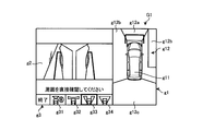
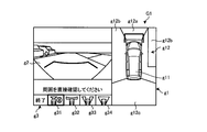
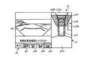
本実施形態では、CPU14a(制御部の一例)は、操作入力部10が操作されて、車両周辺監視用画面G1の表示を指示する操作情報が入力されると、図4Aに示す車両周辺監視用画面G1を表示装置8に表示する。車両周辺監視用画面G1(第1画面の一例)は、図4Aに示すように、車両1を上から見た俯瞰画像g1(第1画像の一例)と、車両1の周囲で撮像対象となる領域(第1領域の一例)のうち一部の領域(第2領域の一例、本実施形態では、車両1の前方の領域である前方領域、前方領域より広域の広角領域、車両1の車幅方向の左側および右側の領域であるサイド領域、または車両1の床下の領域である床下領域)を撮像部16により撮像して得られた撮像画像g2(第2画像の一例)と、車両1の周囲で撮像対象となる領域のうち撮像画像g2を表示する領域を選択するためのGUI(Graphic User Interface)である選択用画像g3と、を含む。
In the present embodiment, the CPU 14a (an example of the control unit) operates the vehicle periphery monitoring shown in FIG. 4A when the operation input unit 10 is operated and the operation information for instructing the display of the vehicle periphery monitoring screen G1 is input. The screen G1 is displayed on the display device 8. As shown in FIG. 4A, the vehicle periphery monitoring screen G1 (an example of the first screen) is an imaging target when the vehicle 1 is viewed from above and an overhead image g1 (an example of the first image). A part of the region (an example of the first region) (an example of the second region, in this embodiment, a front region that is a region in front of the vehicle 1, a wide-angle region wider than the front region, the vehicle width of the vehicle 1) A captured image g2 (an example of a second image) obtained by capturing an image of a side region that is the left and right regions of the direction or an underfloor region that is an underfloor region of the vehicle 1) And a selection image g3 that is a GUI (Graphic User Interface) for selecting a region for displaying the captured image g2 from among the regions to be imaged around.
本実施形態では、俯瞰画像g1は、図4Aに示すように、車両1を上から見た車両画像g11と、当該車両1の周囲の領域を上から見た周囲画像g12と、を含む。CPU14aは、撮像部16aの撮像により得られた画像を、前方領域を上から見た画像に変換(所謂、視点変換)した周囲画像g12aを生成する。また、CPU14aは、撮像部16c,16dの撮像により得られた2つの画像を、左側領域および右側領域を上から見た画像に変換した周囲画像g12bを生成する。また、CPU14aは、撮像部16bの撮像により得られた画像を、車両1の後方領域を上から見た画像に変換した周囲画像g12cを生成する。そして、CPU14aは、周囲画像g12aと、周囲画像g12bと、周囲画像g12cとを組み合わせた画像を、周囲画像g12とする。
In this embodiment, as shown in FIG. 4A, the bird's-eye view image g1 includes a vehicle image g11 when the vehicle 1 is viewed from above, and a surrounding image g12 when the region around the vehicle 1 is viewed from above. The CPU 14a generates a surrounding image g12a obtained by converting an image obtained by imaging by the imaging unit 16a into an image obtained by viewing the front area from above (so-called viewpoint conversion). Further, the CPU 14a generates a surrounding image g12b obtained by converting the two images obtained by the imaging of the imaging units 16c and 16d into images obtained by viewing the left area and the right area from above. In addition, the CPU 14a generates a surrounding image g12c obtained by converting an image obtained by imaging by the imaging unit 16b into an image obtained by viewing the rear region of the vehicle 1 from above. Then, the CPU 14a sets an image obtained by combining the surrounding image g12a, the surrounding image g12b, and the surrounding image g12c as the surrounding image g12.
本実施形態では、CPU14aは、車両周辺監視用画面G1の表示を指示する操作情報が入力された後、最初に、車両周辺監視用画面G1に含める撮像画像g2には、図4Aに示すように、撮像部16により前方領域を撮像して得られた画像を用いる。
In this embodiment, after the operation information instructing the display of the vehicle periphery monitoring screen G1 is input, the CPU 14a first displays the captured image g2 included in the vehicle periphery monitoring screen G1 as shown in FIG. 4A. The image obtained by imaging the front area by the imaging unit 16 is used.
また、本実施形態では、CPU14aは、図4Aに示すように、撮像画像g2を表示する領域として前方領域を選択するための選択用画像g31、撮像画像g2を表示する領域として広角領域を選択するための選択用画像g32、撮像画像g2を表示する領域としてサイド領域を選択するための選択用画像g33、および撮像画像g2を表示する領域として床下領域を選択するための選択用画像g34を、選択用画像g3として車両周辺監視用画面G1に含める。本実施形態では、CPU14aは、選択用画像g3を車両周辺監視用画面G1に含めているが、少なくとも俯瞰画像g1および撮像画像g2が車両周辺監視用画面G1に含まれていれば良い。
In the present embodiment, as shown in FIG. 4A, the CPU 14a selects a selection image g31 for selecting the front area as the area for displaying the captured image g2, and the wide-angle area as the area for displaying the captured image g2. A selection image g32 for selecting, a selection image g33 for selecting a side region as a region for displaying the captured image g2, and a selection image g34 for selecting an underfloor region as a region for displaying the captured image g2. The image g3 is included in the vehicle periphery monitoring screen G1. In the present embodiment, the CPU 14a includes the selection image g3 in the vehicle periphery monitoring screen G1, but it is sufficient that at least the overhead image g1 and the captured image g2 are included in the vehicle periphery monitoring screen G1.
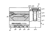
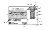
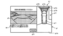
ここで、選択用画像g3を用いて撮像画像g2を切り替える動作について説明する。CPU14aは、操作入力部10により選択用画像g3に対するタッチ操作が検出されて、当該選択用画像g3を用いてユーザが選択した領域(以下、選択領域と言う。例えば、サイド領域)を示す操作情報が入力されると、車両1の周囲で撮像対象となる領域に含まれる一部でありかつユーザにより選択された選択領域(第3領域の一例、本実施形態では、入力された操作情報が示す領域)を特定する。そして、CPU14aは、図5Bに示すように、選択領域を撮像部16(例えば、撮像部16c,16d)により撮像して得られた画像である切替後画像(第3画像の一例)を、当該切替後画像の一つ前に表示されていた画像である切替前画像(第2画像の一例)に切り替えて撮像画像g2として表示装置8上に表示する。
Here, an operation of switching the captured image g2 using the selection image g3 will be described. The CPU 14a detects the touch operation on the selection image g3 by the operation input unit 10, and the operation information indicating an area (hereinafter referred to as a selection area, for example, a side area) selected by the user using the selection image g3. Is input, a selection area (an example of a third area, which is indicated by the input operation information in the present embodiment) is a part included in the area to be imaged around the vehicle 1 and selected by the user. Area). Then, as illustrated in FIG. 5B, the CPU 14a displays the post-switching image (an example of the third image) that is an image obtained by imaging the selection area by the imaging unit 16 (for example, the imaging units 16c and 16d). The image is switched to the pre-switching image (an example of the second image) that is the image displayed immediately before the post-switching image, and is displayed on the display device 8 as the captured image g2.
CPU14aは、切替前画像から切替後画像に切り替えられる時点より前に(本実施形態では、切替前画像から切替後画像に切り替わるまでの間)、俯瞰画像g1内に、識別画像g13(識別情報の一例)を表示する。ここで、識別画像g13は、ユーザが選択した選択領域を識別する画像である。これにより、切替前画像から切替後画像に切り替るまでの間に、識別画像g13が表示されることにより、ユーザが、次に表示される画像がいずれの領域であるかを容易に認識することができる。本実施形態では、識別画像g13は、選択領域に対応する俯瞰画像g1の領域に重畳表示される情報である。これにより、車両1の周囲で撮像対象となる領域のうち、次に表示される画像がいずれの領域であるかをユーザが容易に把握することができる。本実施形態の識別画像g13は、識別情報に相当する。
Prior to the time when the pre-switching image is switched to the post-switching image (in this embodiment, until the switching from the pre-switching image to the post-switching image), the CPU 14a includes the identification image g13 (the identification information of the identification information). Example) is displayed. Here, the identification image g13 is an image for identifying the selection region selected by the user. As a result, the identification image g13 is displayed before the switching from the pre-switching image to the post-switching image, so that the user can easily recognize which region the next displayed image is. Can do. In the present embodiment, the identification image g13 is information that is displayed in a superimposed manner on the area of the overhead image g1 that corresponds to the selected area. Accordingly, the user can easily grasp which region of the image to be imaged around the vehicle 1 is the next image to be displayed. The identification image g13 of the present embodiment corresponds to identification information.
本実施形態では、CPU14aは、切替前画像から切替後画像に切り替えられる時点より前に、俯瞰画像g1が含む周囲画像g12のうち選択領域に対応する領域を他の領域と異なる表示態様とする識別画像g13を、俯瞰画像g1に重畳表示する。ここで、他の領域と異なる表示態様とは、周囲画像g12のうち選択領域に対応する領域の色を、他の領域と異ならせたり、当該選択領域に対応する領域を点滅させたりすることである。例えば、図4Bに示すように、CPU14aは、選択用画像g33にタッチ操作が検出されて、サイド領域が選択領域として選択された場合、周囲画像g12bのサイド領域に対応する領域を、他の領域とは異なる表示態様とする識別画像g13を、俯瞰画像g1に重畳表示する。
In the present embodiment, the CPU 14a identifies the area corresponding to the selected area in the surrounding image g12 included in the overhead image g1 as a display mode different from the other areas before the time point when the pre-switching image is switched to the post-switching image. The image g13 is superimposed and displayed on the overhead image g1. Here, the display mode different from the other areas is that the color of the area corresponding to the selected area in the surrounding image g12 is different from that of the other area, or the area corresponding to the selected area is blinked. is there. For example, as illustrated in FIG. 4B, when the touch operation is detected in the selection image g33 and the side area is selected as the selection area, the CPU 14a sets the area corresponding to the side area of the surrounding image g12b to another area. An identification image g13 having a display mode different from the above is superimposed on the overhead image g1.
本実施形態では、CPU14aは、周囲画像g12のうち選択領域に対応する領域を他の領域と異なる表示態様とする識別画像g13を俯瞰画像g1に重畳表示させているが、切替前画像から切替後画像に切り替えられる時点よりも前に、俯瞰画像g1内に、識別画像g13を表示するものであれば、これに限定するものではない。例えば、CPU14aは、選択領域を表すテキスト(例えば、「前方領域が選択されました。」等)を識別画像g13として俯瞰画像g1内に表示させても良い。本実施形態では、CPU14aは、識別画像g13を俯瞰画像g1に重畳表示させているが、識別画像g13の表示によって俯瞰画像g1が視認できなくなる印象を与えないために、識別画像g13を通じて俯瞰画像g1が透けて見える態様で、識別画像g13を俯瞰画像g1に重畳表示させても良い。
In the present embodiment, the CPU 14a superimposes and displays the identification image g13 in which the region corresponding to the selected region in the surrounding image g12 is displayed differently from the other regions on the overhead image g1, but after switching from the pre-switching image. The present invention is not limited to this as long as the identification image g13 is displayed in the bird's-eye view image g1 before the time of switching to the image. For example, the CPU 14a may display text representing the selected area (for example, “the front area has been selected”) as the identification image g13 in the overhead image g1. In the present embodiment, the CPU 14a superimposes the identification image g13 on the overhead image g1, but in order not to give an impression that the overhead image g1 cannot be visually recognized due to the display of the identification image g13, the overhead image g1 is transmitted through the identification image g13. The identification image g13 may be superimposed and displayed on the overhead view image g1 in such a manner that can be seen through.
さらに、CPU14aは、図4Dに示すように、切替前画像から切替後画像に切り替るまでの間に、俯瞰画像g1を車両周辺監視用画面G1に表示したまま、切替後画像の表示に先立って、切替前画像に代えて黒画像g4を表示する。これにより、切替前画像から切替後画像に切り替わる際に、俯瞰画像g1を常に視認することができかつ撮像画像g2が切り替わったタイミングを視認することができるので、撮像画像g2が切り替わったのか否かをユーザが容易に把握できる。本実施形態では、CPU14aは、切替後画像の表示に先立って、予め設定された時間、黒画像g4を表示し続けるものとする。これにより、撮像画像g2が切り替わったことをユーザがより容易に把握することができる。
Further, as shown in FIG. 4D, the CPU 14a keeps displaying the overhead image g1 on the vehicle periphery monitoring screen G1 before switching from the pre-switching image to the post-switching image, prior to displaying the post-switching image. The black image g4 is displayed instead of the pre-switching image. Thereby, when switching from the pre-switching image to the post-switching image, the bird's-eye view image g1 can always be visually recognized, and the timing at which the captured image g2 is switched can be viewed, so whether or not the captured image g2 has been switched. Can be easily grasped by the user. In the present embodiment, it is assumed that the CPU 14a continues to display the black image g4 for a preset time before displaying the post-switching image. Thereby, the user can grasp | ascertain more easily that the captured image g2 switched.
また、CPU14aは、図4Cに示すように、切替前画像に代えて黒画像g4を表示するまでの間、切替前画像の輝度を徐々に下げても良い。すなわち、CPU14aは、切替前画像に代えて黒画像g4を表示するまでの間、切替前画像をフェードアウトさせた後に、黒画像g4を表示する。これにより、撮像画像g2が短い時間で切り替わることを防止できるので、撮像画像g2が切り替わったか否かをユーザが容易に把握することができる。
Further, as shown in FIG. 4C, the CPU 14a may gradually decrease the luminance of the pre-switching image until the black image g4 is displayed instead of the pre-switching image. That is, the CPU 14a displays the black image g4 after fading out the pre-switching image until the black image g4 is displayed instead of the pre-switching image. Thereby, since it can prevent that the captured image g2 switches in a short time, the user can grasp | ascertain easily whether the captured image g2 switched.
その後、CPU14aは、図5Bに示すように、黒画像g4の表示を開始してから予め設定された時間が経過すると、切替後画像を撮像画像g2として車両周辺監視用画面G1に含める。本実施形態では、CPU14aは、切替後画像を撮像画像g2として車両周辺監視用画面G1に含めた後(すなわち、切替前画像から切替後画像に切り替えた後)、所定時間、識別画像g13を表示し続ける。これにより、撮像画像g2が切り替えられた後、識別画像g13が直ちに非表示になることを防止できるので、撮像画像g2が切り替えられた後、ユーザが選択した領域を撮像して得られた撮像画像g2が表示されたか否かを確認することができる。
Thereafter, as shown in FIG. 5B, when a preset time has elapsed since the start of displaying the black image g4, the CPU 14a includes the post-switching image as the captured image g2 in the vehicle periphery monitoring screen G1. In the present embodiment, the CPU 14a displays the identification image g13 for a predetermined time after including the post-switching image as the captured image g2 in the vehicle periphery monitoring screen G1 (that is, after switching from the pre-switching image to the post-switching image). Keep doing. This prevents the identification image g13 from being immediately hidden after the captured image g2 is switched. Therefore, the captured image obtained by capturing the region selected by the user after the captured image g2 is switched. It can be confirmed whether or not g2 is displayed.
また、CPU14aは、図5Aに示すように、黒画像g4に代えて切替後画像を表示するまでの間、切替後画像の輝度を徐々に上げても良い。すなわち、CPU14aは、黒画像g4に代えて切替後画像を表示するまでの間、切替後画像をフェードインさせて、切替後画像を表示する。これにより、撮像画像g2が短い時間で切り替わることを防止できるので、撮像画像g2が切り替わったか否かをユーザが容易に把握することができる。
Further, as shown in FIG. 5A, the CPU 14a may gradually increase the brightness of the post-switching image until the post-switching image is displayed instead of the black image g4. That is, the CPU 14a fades in the post-switching image and displays the post-switching image until the post-switching image is displayed instead of the black image g4. Thereby, since it can prevent that the captured image g2 switches in a short time, the user can grasp | ascertain easily whether the captured image g2 switched.
そして、CPU14aは、図5Cに示すように、切替後画像の表示を開始してから所定時間経過後、識別画像g13を非表示とする。また、CPU14aは、識別画像g13を非表示とした後、操作入力部10によって撮像画像g2に対するタッチ操作が検出された場合に、現在、撮像画像g2を表示している選択領域を識別する画像を表示(すなわち、識別画像g13再表示)させても良い。これにより、識別画像g13が非表示となった後も、撮像画像g2にタッチ操作することによって、いずれの領域を撮像して得られた撮像画像g2が表示されているかを容易に特定することができる。さらに、CPU14aは、図5Dに示すように、俯瞰画像g1および選択用画像g3を非表示としかつ切替後画像を車両周辺監視用画面G1に全画面表示させることによって、切替後画像をより確認し易くすることも可能である。本実施形態では、CPU14aは、切替前画像が切替後画像に切り替わった後、所定時間経過後に識別画像g13を非表示に変更しているが、これに限定するものではなく、例えば、切替前画像が切替後画像に切り替えられたと同時に、識別画像g13を非表示に変更しても良い。
Then, as shown in FIG. 5C, the CPU 14a hides the identification image g13 after a predetermined time has elapsed since the display of the post-switching image was started. In addition, when the operation input unit 10 detects a touch operation on the captured image g2 after the identification image g13 is not displayed, the CPU 14a displays an image for identifying a selection region that currently displays the captured image g2. It may be displayed (that is, the identification image g13 is redisplayed). Thereby, even after the identification image g13 is not displayed, it is possible to easily identify which area the captured image g2 obtained by capturing an image is displayed by performing a touch operation on the captured image g2. it can. Further, as shown in FIG. 5D, the CPU 14a makes the bird's-eye view image g1 and the selection image g3 non-displayed and displays the post-switching image on the vehicle periphery monitoring screen G1, thereby further confirming the post-switching image. It can also be made easier. In the present embodiment, the CPU 14a changes the identification image g13 to non-display after a predetermined time has elapsed after the pre-switching image is switched to the post-switching image. However, the present invention is not limited to this. The identification image g13 may be changed to non-display at the same time that is switched to the post-switching image.
次に、図6A~図6Dおよび図7A~図7Dを用いて、車両周辺監視用画面G1に含める撮像画像g2を、前方領域を撮像して得られた画像(切替前画像)から、広角領域を撮像して得られた画像(切替後画像)に切り替えて表示する処理について説明する。図6A~図6Dおよび図7A~図7Dは、第1の実施形態にかかる車両において表示される車両周辺監視用画面内の撮像画像の切替処理の一例を説明するための図である。
Next, using FIG. 6A to FIG. 6D and FIG. 7A to FIG. 7D, the captured image g2 to be included in the vehicle periphery monitoring screen G1 is converted into a wide-angle region from the image (image before switching) obtained by capturing the front region. A process of switching and displaying an image obtained by imaging (image after switching) will be described. FIGS. 6A to 6D and FIGS. 7A to 7D are diagrams for explaining an example of switching processing of captured images in the vehicle periphery monitoring screen displayed in the vehicle according to the first embodiment.
まず、CPU14aは、図6Aに示すように、撮像部16aの撮像により得られた撮像画像g2を含む車両周辺監視用画面G1を表示装置8に表示しているものとする。その後、CPU14aは、図6Bに示すように、選択用画像g32に対するタッチ操作が検出されて、広角領域が選択領域として選択された場合、周囲画像g12のうち広角領域に対応する領域を、他の領域とは異なる表示態様とする識別画像g13を、車両周辺監視用画面G1に重畳表示する。
First, it is assumed that the CPU 14a displays a vehicle periphery monitoring screen G1 including a captured image g2 obtained by imaging by the imaging unit 16a on the display device 8, as shown in FIG. 6A. Thereafter, as shown in FIG. 6B, when a touch operation on the selection image g32 is detected and the wide-angle area is selected as the selection area, the CPU 14a selects an area corresponding to the wide-angle area in the surrounding image g12 as another area. An identification image g13 having a display mode different from that of the region is superimposed and displayed on the vehicle periphery monitoring screen G1.
その後、CPU14aは、図6Dに示すように、撮像画像g2が切り替わる前に、俯瞰画像g1を車両周辺監視用画面G1に表示したまま、予め設定された時間、切替前画像に替えて黒画像g4を表示する。また、CPU14aは、図6Cに示すように、切替前画像に代えて黒画像g4を表示するまでの間、切替前画像の輝度を徐々に下げても良い。
Thereafter, as shown in FIG. 6D, the CPU 14a changes the pre-switching image for the preset time and the black image g4 while the overhead image g1 is displayed on the vehicle periphery monitoring screen G1 before the captured image g2 is switched. Is displayed. Further, as illustrated in FIG. 6C, the CPU 14a may gradually decrease the luminance of the pre-switching image until the black image g4 is displayed instead of the pre-switching image.
次に、CPU14aは、図7Bに示すように、黒画像g4の表示を開始してから予め設定された時間が経過すると、広角領域を撮像部16aにより撮像して得られた画像(切替後画像)を撮像画像g2として車両周辺監視用画面G1に含める。また、CPU14aは、図7Aに示すように、黒画像g4に代えて切替後画像を表示するまでの間、切替後画像の輝度を徐々に上げても良い。
Next, as shown in FIG. 7B, when a preset time has elapsed since the display of the black image g4 is started, the CPU 14a captures an image (post-switching image) obtained by imaging the wide-angle region with the imaging unit 16a. ) As a captured image g2 in the vehicle periphery monitoring screen G1. Further, as illustrated in FIG. 7A, the CPU 14a may gradually increase the luminance of the post-switching image until the post-switching image is displayed instead of the black image g4.
そして、CPU14aは、図7Cに示すように、切替後画像の表示を開始してから所定時間経過後、識別画像g13を非表示とする。その際、CPU14aは、図7Dに示すように、俯瞰画像g1および選択用画像g3を非表示としかつ切替後画像を車両周辺監視用画面G1に全画面表示させることによって、切替後画像をより確認し易くすることも可能である。
Then, as shown in FIG. 7C, the CPU 14a hides the identification image g13 after a predetermined time has elapsed since the display of the post-switching image was started. At that time, as shown in FIG. 7D, the CPU 14a hides the overhead image g1 and the selection image g3 and displays the switched image on the vehicle periphery monitoring screen G1, thereby further confirming the switched image. It is also possible to make it easier.
次に、図8A~図8Dおよび図9A~図9Dを用いて、車両周辺監視用画面G1に含める撮像画像g2を、前方領域を撮像して得られた画像(切替前画像)から、床下領域を撮像して得られた画像(切替後画像)に切り替えて表示する処理について説明する。図8A~図8Dおよび図9A~図9Dは、第1の実施形態にかかる車両において表示される車両周辺監視用画面内の撮像画像の切替処理の一例を説明するための図である。
Next, using FIG. 8A to FIG. 8D and FIG. 9A to FIG. 9D, the captured image g2 to be included in the vehicle periphery monitoring screen G1 is converted into an underfloor region from an image (image before switching) obtained by capturing the front region. A process of switching and displaying an image obtained by imaging (image after switching) will be described. FIGS. 8A to 8D and FIGS. 9A to 9D are diagrams for explaining an example of switching processing of captured images in the vehicle periphery monitoring screen displayed in the vehicle according to the first embodiment.
まず、CPU14aは、図8Aに示すように、撮像部16aの撮像により得られた撮像画像g2を含む車両周辺監視用画面G1を表示装置8に表示しているものとする。その後、CPU14aは、図8Bに示すように、選択用画像g34に対するタッチ操作が検出されて、床下領域が選択領域として選択された場合、周囲画像g12のうち広角領域に対応する領域を、他の領域とは異なる表示態様とする識別画像g13を、車両周辺監視用画面G1に重畳表示する。
First, it is assumed that the CPU 14a displays a vehicle periphery monitoring screen G1 including a captured image g2 obtained by imaging by the imaging unit 16a on the display device 8, as shown in FIG. 8A. After that, as shown in FIG. 8B, when the touch operation on the selection image g34 is detected and the underfloor area is selected as the selection area, the CPU 14a changes the area corresponding to the wide-angle area in the surrounding image g12 to the other area. An identification image g13 having a display mode different from that of the region is superimposed and displayed on the vehicle periphery monitoring screen G1.
その後、CPU14aは、図8Dに示すように、撮像画像g2が切り替わる前に、俯瞰画像g1を車両周辺監視用画面G1に表示したまま、予め設定された時間、切替前画像に替えて黒画像g4を表示する。また、CPU14aは、図8Cに示すように、切替前画像に代えて黒画像g4を表示するまでの間、切替前画像の輝度を徐々に下げても良い。
Thereafter, as shown in FIG. 8D, the CPU 14a replaces the pre-switching image with the pre-switching image for a preset time while the overhead image g1 is displayed on the vehicle periphery monitoring screen G1 before the captured image g2 is switched. Is displayed. Further, as illustrated in FIG. 8C, the CPU 14a may gradually decrease the luminance of the pre-switching image until the black image g4 is displayed instead of the pre-switching image.
次に、CPU14aは、図9Bに示すように、黒画像g4の表示を開始してから予め設定された時間が経過すると、撮像部16eの撮像により得られた画像(切替後画像)を撮像画像g2として車両周辺監視用画面G1に含める。また、CPU14aは、図9Aに示すように、黒画像g4に代えて切替後画像を表示するまでの間、切替後画像の輝度を徐々に上げる。本実施形態では、撮像部16eの撮像により得られた画像を、床下領域を撮像して得られた画像として表示しているが、これに限定するものではなく、例えば、撮像部16aにより前方領域を撮像して得られた画像を記憶しておき、当該記憶された画像を、床下領域を上からリアルタイムで見た画像に視点変換して表示しても良い。これにより、床下を直接撮像して得られた画像に比べ、撮像部16aにより車両1の前方を撮像して得られた画像によれば、車両1のタイヤで隠されない広域な床下領域の路面状況を表示することができる。さらに、図9A~図9Dの撮像画像g2に示すように、車両1のタイヤおよび車両1の外部を示す指標g21を重畳表示することにより、ユーザは、車両1の床下領域のうちどの領域の画像が表示されたかを容易に把握することができる。
Next, as illustrated in FIG. 9B, when a preset time has elapsed since the display of the black image g4 is started, the CPU 14a captures an image (switched image) obtained by imaging by the imaging unit 16e. It is included in the vehicle periphery monitoring screen G1 as g2. Further, as shown in FIG. 9A, the CPU 14a gradually increases the luminance of the post-switching image until the post-switching image is displayed instead of the black image g4. In the present embodiment, the image obtained by imaging by the imaging unit 16e is displayed as an image obtained by imaging the underfloor region. However, the present invention is not limited to this, and for example, the front region is captured by the imaging unit 16a. It is also possible to store an image obtained by capturing an image of the image and convert the stored image into an image obtained by viewing the underfloor region in real time from above and display the image. Thereby, according to the image obtained by imaging the front of the vehicle 1 by the imaging unit 16a as compared with the image obtained by directly imaging the underfloor, the road surface condition of the wide underfloor region that is not hidden by the tire of the vehicle 1 Can be displayed. Further, as shown in the captured images g2 of FIGS. 9A to 9D, by displaying the tire g of the vehicle 1 and the index g21 indicating the outside of the vehicle 1 in an overlapping manner, the user can select which region of the vehicle 1 under the floor area. Can be easily grasped.
そして、CPU14aは、図9Cに示すように、切替後画像の表示を開始してから所定時間経過後、識別画像g13を非表示とする。その際、CPU14aは、図9Dに示すように、俯瞰画像g1および選択用画像g3を非表示としかつ切替後画像を車両周辺監視用画面G1に全画面表示させることによって、切替後画像をより確認し易くすることも可能である。
Then, as shown in FIG. 9C, the CPU 14a hides the identification image g13 after a predetermined time has elapsed since the display of the post-switching image was started. At that time, as shown in FIG. 9D, the CPU 14a hides the overhead view image g1 and the selection image g3 and displays the switched image on the vehicle periphery monitoring screen G1 so as to confirm the switched image. It is also possible to make it easier.
このように、第1の実施形態の車両1によれば、切替前画像から切替後画像に切り替るまでの間に、識別画像g13が表示されることにより、ユーザが、次に表示される画像がいずれの領域であるかを容易に認識することができる。
As described above, according to the vehicle 1 of the first embodiment, the identification image g13 is displayed before the switching from the pre-switching image to the post-switching image. Can be easily recognized.
(第2の実施形態)
本実施形態は、車両周辺監視用画面が含む車両画像を、選択領域を選択するための選択用画像として用いる例である。以下の説明では、第1の実施形態と同様の箇所については説明を省略する。 (Second Embodiment)
The present embodiment is an example in which a vehicle image included in a vehicle periphery monitoring screen is used as a selection image for selecting a selection region. In the following description, description of the same parts as those in the first embodiment is omitted.
図10A~図10E、図11A~図11E、および図12A~図12Cは、第2の実施形態にかかる車両において表示される車両周辺監視用画面の一例を説明するための図である。本実施形態では、CPU14aは、図10Aに示すように、俯瞰画像g1および撮像画像g2に加えて、当該車両画像g11を用いて選択領域を選択可能である旨のメッセージM1(例えば、「車両アイコンを押下すると、表示エリアを選択できます」)を含む車両周辺監視用画面G1を表示装置8に表示する。
FIG. 10A to FIG. 10E, FIG. 11A to FIG. 11E, and FIG. 12A to FIG. 12C are diagrams for explaining an example of the vehicle periphery monitoring screen displayed on the vehicle according to the second embodiment. In the present embodiment, as shown in FIG. 10A, the CPU 14a displays a message M1 indicating that a selection area can be selected using the vehicle image g11 in addition to the overhead image g1 and the captured image g2 (for example, “vehicle icon The display area can be selected by depressing “” to display the vehicle periphery monitoring screen G 1 including “) on the display device 8.
そして、CPU14aは、図10Bに示すように、操作入力部10によって車両画像g11に対するタッチ操作が検出されると、車両画像g11の表示態様を所定の表示態様(例えば、点滅状態、ハイライト表示)に変更する。さらに、CPU14aは、操作入力部10によって車両画像g11に対するタッチ操作が検出される度に、選択領域として選択可能な複数の候補領域(本実施形態では、前方領域、広角領域、サイド領域、および床下領域)それぞれに対応する複数の候補領域画像g16を、予め設定された順番で、切り替えて俯瞰画像g1に表示する。ここで、候補領域画像g16は、周辺画像g12のうち候補領域に対応する領域を他の領域と異なる表示態様(例えば、点滅状態、ハイライト表示)とする画像である。また、本実施形態では、CPU14aは、前方領域に対応する候補領域画像g16a、広角領域に対応する候補領域画像g16b、サイド領域に対応する候補領域画像g16c、および床下領域に対応する候補領域画像g16dを、複数の候補領域画像g16として切り替えて表示する。
Then, as shown in FIG. 10B, when the touch operation on the vehicle image g11 is detected by the operation input unit 10, the CPU 14a changes the display mode of the vehicle image g11 to a predetermined display mode (for example, blinking state, highlight display). Change to Further, the CPU 14a has a plurality of candidate areas (in this embodiment, a front area, a wide-angle area, a side area, and an underfloor area) that can be selected as a selection area each time a touch operation on the vehicle image g11 is detected by the operation input unit 10. A plurality of candidate region images g16 corresponding to each region) are switched and displayed in the overhead view image g1 in a preset order. Here, the candidate area image g16 is an image in which the area corresponding to the candidate area in the peripheral image g12 is displayed differently from the other areas (for example, blinking state, highlighted display). Further, in the present embodiment, the CPU 14a, the candidate area image g16a corresponding to the front area, the candidate area image g16b corresponding to the wide-angle area, the candidate area image g16c corresponding to the side area, and the candidate area image g16d corresponding to the underfloor area. Are switched and displayed as a plurality of candidate area images g16.
本実施形態では、CPU14aは、図10A~図10Eおよび図11A~図11Cに示すように、候補領域画像g16a、候補領域画像g16b、候補領域画像g16c、および候補領域画像g16dの順に、切り替えて表示する。本実施形態では、操作入力部10によって車両画像g11に対するタッチ操作が検出される度に、複数の候補領域画像g16を切り替えて表示しているが、これに限定するものではなく、例えば、撮像画像g2に対するタッチ操作が検出される度若しくは操作入力部10によってスワイプ操作が検出される度に、複数の候補領域画像g16を切り替えて表示しても良い。若しくは、CPU14aは、操作入力部10によって検出されたスワイプ操作の方向に応じて、複数の候補領域画像g16のうち表示する候補領域画像g16を切り替えても良い。また、本実施形態では、操作入力部10の一例であるタッチパネルにより検出されるタッチ操作に応じて、複数の候補領域画像g16を切り替えて表示しているが、例えば、ダッシュボードやインパネ付近やステアリング等に設置されたハードウェアスイッチのサイクリック操作に応じて、複数の候補領域画像g16を切り替えて表示しても良い。
In the present embodiment, as shown in FIGS. 10A to 10E and FIGS. 11A to 11C, the CPU 14a switches and displays the candidate area image g16a, the candidate area image g16b, the candidate area image g16c, and the candidate area image g16d in this order. To do. In this embodiment, every time a touch operation on the vehicle image g11 is detected by the operation input unit 10, the plurality of candidate region images g16 are switched and displayed. However, the present invention is not limited to this, and for example, a captured image Each time a touch operation on g2 is detected or a swipe operation is detected by the operation input unit 10, a plurality of candidate area images g16 may be switched and displayed. Alternatively, the CPU 14a may switch the candidate area image g16 to be displayed among the plurality of candidate area images g16 according to the direction of the swipe operation detected by the operation input unit 10. In the present embodiment, a plurality of candidate area images g16 are switched and displayed according to a touch operation detected by a touch panel that is an example of the operation input unit 10, but for example, near a dashboard, an instrument panel, or a steering wheel A plurality of candidate area images g16 may be switched and displayed in response to a cyclic operation of a hardware switch installed in the above.
その後、図11Dに示すように、操作入力部10によって候補領域画像g16(例えば、候補領域画像g16c)に対するタッチ操作が検出されると、CPU14aは、当該タッチ操作が検出された候補領域画像g16に対応する候補選択領域(例えば、サイド領域)が選択領域として選択されたと判断する。若しくは、操作入力部10によって車両画像g11に対する長押しが検出されると、CPU14aは、最後に表示された候補領域画像g16に対応する候補選択領域が選択領域として選択されたと判断しても良い。そして、CPU14aは、図11Eに示すように、第1の実施形態と同様にして、選択領域を撮像して得られた画像(切替後画像)を撮像画像g2として車両周辺監視用画面G1に含める。また、CPU14aは、図11Eに示すように、第1の実施形態と同様にして、切替前画像から切替後画像に切り替えられる時点より前に、俯瞰画像g1内に、識別画像g13を重畳表示する。
Thereafter, as illustrated in FIG. 11D, when a touch operation on the candidate area image g16 (for example, the candidate area image g16c) is detected by the operation input unit 10, the CPU 14a displays the candidate area image g16 in which the touch operation is detected. It is determined that the corresponding candidate selection area (for example, the side area) has been selected as the selection area. Alternatively, when a long press on the vehicle image g11 is detected by the operation input unit 10, the CPU 14a may determine that the candidate selection area corresponding to the last displayed candidate area image g16 has been selected as the selection area. Then, as shown in FIG. 11E, the CPU 14a includes an image (post-switching image) obtained by imaging the selected region as the captured image g2 in the vehicle periphery monitoring screen G1, as in the first embodiment. . Further, as shown in FIG. 11E, the CPU 14a superimposes and displays the identification image g13 in the overhead image g1 before the time point when the pre-switching image is switched to the post-switching image, as in the first embodiment. .
一方、図12Aおよび図12Bに示すように、複数の候補領域画像g16が切り替えて表示されている途中で、選択領域の選択の中止を指示するための中止ボタンg15に対するタッチ操作が操作入力部10によって検出されると、CPU14aは、図12Cに示すように、車両画像g11の表示態様を元の表示態様に戻し、選択領域を選択できない状態とする。
On the other hand, as shown in FIGS. 12A and 12B, while the plurality of candidate area images g16 are switched and displayed, a touch operation on the stop button g15 for instructing to cancel selection of the selected area is performed on the operation input unit 10. As shown in FIG. 12C, the CPU 14a returns the display mode of the vehicle image g11 to the original display mode so that the selection area cannot be selected.
このように、第2の実施形態にかかる車両1によれば、俯瞰画像g1が含む車両画像g11をタッチ操作することによって、複数の候補領域画像g16を切り替えて表示させ、かつ候補領域画像g16をタッチ操作することで選択領域を選択することができるので、選択領域を選択する際の操作を直感的に行うことができる。
Thus, according to the vehicle 1 according to the second embodiment, by touching the vehicle image g11 included in the overhead image g1, the plurality of candidate area images g16 are switched and displayed, and the candidate area image g16 is displayed. Since the selection area can be selected by performing a touch operation, an operation for selecting the selection area can be performed intuitively.
以上説明したとおり、第1,2の実施形態によれば、切替前画像から切替後画像に切り替るまでの間に、識別画像g13が表示されることにより、ユーザが、次に表示される画像がいずれの領域であるかを容易に認識することができる。
As described above, according to the first and second embodiments, the identification image g13 is displayed before the switching from the pre-switching image to the post-switching image, so that the user can display the next image. Can be easily recognized.
本発明のいくつかの実施形態を説明したが、これらの実施形態は、例として提示したものであり、発明の範囲を限定することは意図していない。これら新規な実施形態は、その他の様々な形態で実施されることが可能であり、発明の要旨を逸脱しない範囲で、種々の省略、置き換え、変更を行うことができる。これら実施形態やその変形は、発明の範囲や要旨に含まれるとともに、請求の範囲に記載された発明とその均等の範囲に含まれる。
Although several embodiments of the present invention have been described, these embodiments are presented as examples and are not intended to limit the scope of the invention. These novel embodiments can be implemented in various other forms, and various omissions, replacements, and changes can be made without departing from the scope of the invention. These embodiments and modifications thereof are included in the scope and gist of the invention, and are included in the invention described in the claims and the equivalents thereof.
Claims (5)
- 表示部と、
車両を上から見た第1画像と、車両の周囲で撮像対象となる第1領域のうち一部の第2領域を撮像して得られた第2画像とを含む第1画面を前記表示部に表示し、前記第2画像から、前記第1領域に含まれる一部の領域として選択されかつ前記第2領域とは異なる第3領域を撮像して得られた第3画像へ切り替えて前記表示部上に表示し、前記第2画像が前記第3画像に切り替えられる時点よりも前に、前記第1画像内に、前記第3領域を識別する識別情報を表示する制御部と、
を備えた画像表示制御装置。 A display unit;
The display unit includes a first screen including a first image of the vehicle as viewed from above and a second image obtained by imaging a part of a second region of the first region to be imaged around the vehicle. The display is switched from the second image to a third image selected by imaging a third region that is selected as a partial region included in the first region and is different from the second region. A control unit for displaying identification information for identifying the third region in the first image before the time point when the second image is switched to the third image.
An image display control device. - 前記制御部は、前記第2画像から前記第3画像に切り替るまでの間に、前記第1画像を前記第1画面に表示したまま、前記第3画像に先立って、前記第2画像に代えて黒画像を表示する請求項1に記載の画像表示制御装置。 The controller replaces the second image prior to the third image while the first image is displayed on the first screen during the period from the second image to the third image. The image display control device according to claim 1, wherein a black image is displayed.
- 前記制御部は、前記黒画像が表示されるまで、前記第2画像の輝度を徐々に下げ、前記黒画像が表示された後、前記第3画像の輝度を徐々に上げる請求項2に記載の画像表示制御装置。 The control unit according to claim 2, wherein the control unit gradually decreases the brightness of the second image until the black image is displayed, and gradually increases the brightness of the third image after the black image is displayed. Image display control device.
- 前記識別情報は、前記第3領域に対応する前記第1画像の領域に重畳表示される情報である請求項1から3のいずれか一に記載の画像表示制御装置。 The image display control apparatus according to any one of claims 1 to 3, wherein the identification information is information that is displayed in a superimposed manner on a region of the first image corresponding to the third region.
- 前記制御部は、前記第2画像が前記第3画像に切り替えられたと同時に、または前記第2画像が前記第3画像に切り替わった後、所定時間経過後に前記識別情報を非表示に変更する請求項1から4のいずれか一に記載の画像表示制御装置。 The control unit changes the identification information to non-display after a predetermined time elapses after the second image is switched to the third image or after the second image is switched to the third image. The image display control device according to any one of 1 to 4.
Priority Applications (4)
| Application Number | Priority Date | Filing Date | Title |
|---|---|---|---|
| US15/738,681 US10484651B2 (en) | 2015-06-29 | 2016-06-23 | Image display control device |
| CN201680037469.XA CN107852481B (en) | 2015-06-29 | 2016-06-23 | Image display control device |
| EP16817816.8A EP3316574A4 (en) | 2015-06-29 | 2016-06-23 | Image display control device |
| JP2017526314A JP6555348B2 (en) | 2015-06-29 | 2016-06-23 | Image display control device |
Applications Claiming Priority (2)
| Application Number | Priority Date | Filing Date | Title |
|---|---|---|---|
| JP2015-130276 | 2015-06-29 | ||
| JP2015130276 | 2015-06-29 |
Publications (1)
| Publication Number | Publication Date |
|---|---|
| WO2017002708A1 true WO2017002708A1 (en) | 2017-01-05 |
Family
ID=57608404
Family Applications (1)
| Application Number | Title | Priority Date | Filing Date |
|---|---|---|---|
| PCT/JP2016/068731 WO2017002708A1 (en) | 2015-06-29 | 2016-06-23 | Image display control device |
Country Status (5)
| Country | Link |
|---|---|
| US (1) | US10484651B2 (en) |
| EP (1) | EP3316574A4 (en) |
| JP (1) | JP6555348B2 (en) |
| CN (1) | CN107852481B (en) |
| WO (1) | WO2017002708A1 (en) |
Cited By (1)
| Publication number | Priority date | Publication date | Assignee | Title |
|---|---|---|---|---|
| JPWO2021106434A1 (en) * | 2019-11-25 | 2021-06-03 |
Families Citing this family (6)
| Publication number | Priority date | Publication date | Assignee | Title |
|---|---|---|---|---|
| EP3264250B1 (en) * | 2016-06-27 | 2020-12-09 | Volkswagen Aktiengesellschaft | Method and system for selecting a mode of operation for a vehicle |
| JP6607272B2 (en) * | 2018-03-02 | 2019-11-20 | 株式会社Jvcケンウッド | VEHICLE RECORDING DEVICE, VEHICLE RECORDING METHOD, AND PROGRAM |
| CN110248147B (en) | 2018-09-25 | 2022-08-23 | 浙江大华技术股份有限公司 | Image display method and device |
| JP2022082487A (en) * | 2020-11-23 | 2022-06-02 | 株式会社デンソー | Peripheral image generation apparatus and display control method |
| DE102021201014A1 (en) | 2021-02-04 | 2022-08-04 | Zf Friedrichshafen Ag | All-round view display with a vehicle view |
| JP2022125859A (en) | 2021-02-17 | 2022-08-29 | 株式会社デンソー | Peripheral image display device |
Citations (6)
| Publication number | Priority date | Publication date | Assignee | Title |
|---|---|---|---|---|
| JP2005150938A (en) * | 2003-11-12 | 2005-06-09 | Nissan Motor Co Ltd | System and method for monitoring periphery of vehicle |
| JP2005170285A (en) * | 2003-12-12 | 2005-06-30 | Ichikoh Ind Ltd | Image display device for vehicle |
| JP2007210451A (en) * | 2006-02-09 | 2007-08-23 | Nissan Motor Co Ltd | Display device for vehicle |
| JP2008021234A (en) * | 2006-07-14 | 2008-01-31 | Denso Corp | Driving support image display system and on-vehicle device |
| JP2008024138A (en) * | 2006-07-20 | 2008-02-07 | Denso Corp | Image display device and program |
| JP2010147516A (en) * | 2008-12-16 | 2010-07-01 | Mitsubishi Motors Corp | Vehicle periphery monitoring device |
Family Cites Families (11)
| Publication number | Priority date | Publication date | Assignee | Title |
|---|---|---|---|---|
| US20090273720A1 (en) * | 2005-09-21 | 2009-11-05 | Fujitsu Ten Limited. | Display Apparatus, and Methods for Inspecting and Manufacturing the Same, and Methods for Inspecting and Manufacturing Display Panel |
| JP2008017311A (en) | 2006-07-07 | 2008-01-24 | Nissan Motor Co Ltd | Display apparatus for vehicle and method for displaying circumference video image of vehicle |
| JP2009060404A (en) | 2007-08-31 | 2009-03-19 | Denso Corp | Video processing device |
| JP4962788B2 (en) | 2007-11-02 | 2012-06-27 | 株式会社デンソー | Vehicle periphery monitoring device |
| JP4973564B2 (en) * | 2008-03-27 | 2012-07-11 | 三菱自動車工業株式会社 | Vehicle periphery display device |
| EP2280547A4 (en) * | 2008-05-19 | 2013-02-13 | Panasonic Corp | Vehicle surroundings monitoring device and vehicle surroundings monitoring method |
| JP5523954B2 (en) * | 2010-06-30 | 2014-06-18 | 富士通テン株式会社 | Image display system |
| JP2012244600A (en) * | 2011-05-24 | 2012-12-10 | Fujitsu Ten Ltd | Image display system, image processing apparatus, and image display method |
| WO2014027489A1 (en) * | 2012-08-17 | 2014-02-20 | 本田技研工業株式会社 | Driving assistance device |
| US9956913B2 (en) * | 2013-03-28 | 2018-05-01 | Aisin Seiki Kabushiki Kaisha | Surroundings-monitoring device and computer program product |
| CN104512463B (en) * | 2013-10-04 | 2017-04-26 | 本田技研工业株式会社 | Parking assisting device |
-
2016
- 2016-06-23 JP JP2017526314A patent/JP6555348B2/en active Active
- 2016-06-23 CN CN201680037469.XA patent/CN107852481B/en active Active
- 2016-06-23 EP EP16817816.8A patent/EP3316574A4/en not_active Ceased
- 2016-06-23 WO PCT/JP2016/068731 patent/WO2017002708A1/en active Application Filing
- 2016-06-23 US US15/738,681 patent/US10484651B2/en active Active
Patent Citations (6)
| Publication number | Priority date | Publication date | Assignee | Title |
|---|---|---|---|---|
| JP2005150938A (en) * | 2003-11-12 | 2005-06-09 | Nissan Motor Co Ltd | System and method for monitoring periphery of vehicle |
| JP2005170285A (en) * | 2003-12-12 | 2005-06-30 | Ichikoh Ind Ltd | Image display device for vehicle |
| JP2007210451A (en) * | 2006-02-09 | 2007-08-23 | Nissan Motor Co Ltd | Display device for vehicle |
| JP2008021234A (en) * | 2006-07-14 | 2008-01-31 | Denso Corp | Driving support image display system and on-vehicle device |
| JP2008024138A (en) * | 2006-07-20 | 2008-02-07 | Denso Corp | Image display device and program |
| JP2010147516A (en) * | 2008-12-16 | 2010-07-01 | Mitsubishi Motors Corp | Vehicle periphery monitoring device |
Non-Patent Citations (1)
| Title |
|---|
| See also references of EP3316574A4 * |
Cited By (4)
| Publication number | Priority date | Publication date | Assignee | Title |
|---|---|---|---|---|
| JPWO2021106434A1 (en) * | 2019-11-25 | 2021-06-03 | ||
| WO2021106434A1 (en) * | 2019-11-25 | 2021-06-03 | 富士フイルム株式会社 | Video creation method |
| US11689687B2 (en) | 2019-11-25 | 2023-06-27 | Fujifilm Corporation | Video creation method |
| JP7345561B2 (en) | 2019-11-25 | 2023-09-15 | 富士フイルム株式会社 | Video creation method |
Also Published As
| Publication number | Publication date |
|---|---|
| US10484651B2 (en) | 2019-11-19 |
| JP6555348B2 (en) | 2019-08-07 |
| CN107852481B (en) | 2020-07-28 |
| JPWO2017002708A1 (en) | 2018-04-05 |
| US20180192005A1 (en) | 2018-07-05 |
| EP3316574A1 (en) | 2018-05-02 |
| CN107852481A (en) | 2018-03-27 |
| EP3316574A4 (en) | 2018-05-30 |
Similar Documents
| Publication | Publication Date | Title |
|---|---|---|
| JP6555348B2 (en) | Image display control device | |
| US9308863B2 (en) | Vehicle peripheral observation device | |
| JP5187179B2 (en) | Vehicle periphery monitoring device | |
| JP2014209713A (en) | Periphery monitoring device and program | |
| US20160152264A1 (en) | Vehicle circumference monitoring apparatus | |
| JP2018006921A (en) | Periphery monitoring device | |
| US11669230B2 (en) | Display control device | |
| JP4436392B2 (en) | Video processing device | |
| CN110895443A (en) | Display control device | |
| CN110877574A (en) | Display control device | |
| JP2008141622A (en) | Vehicle surrounding information display apparatus | |
| JP5709460B2 (en) | Driving support system, driving support method, and driving support program | |
| JP6855331B2 (en) | Image transfer device, diagnostic imaging device, and diagnostic imaging system | |
| JP2017069834A (en) | Display control device | |
| JP4840332B2 (en) | Remote control device | |
| JP2020121638A (en) | Display control device | |
| JP4467313B2 (en) | Vehicle periphery imaging device | |
| JP2017143482A (en) | Image display device for vehicle | |
| JP7159598B2 (en) | Perimeter monitoring device | |
| JP6610139B2 (en) | Perimeter monitoring device | |
| JP7159599B2 (en) | Perimeter monitoring device | |
| JP5284452B2 (en) | Vehicle display device | |
| JP7139664B2 (en) | Perimeter monitoring device | |
| JP2006137282A (en) | Remote control device, and display device for vehicle | |
| JP2020120337A (en) | Display control device |
Legal Events
| Date | Code | Title | Description |
|---|---|---|---|
| 121 | Ep: the epo has been informed by wipo that ep was designated in this application |
Ref document number: 16817816 Country of ref document: EP Kind code of ref document: A1 |
|
| ENP | Entry into the national phase |
Ref document number: 2017526314 Country of ref document: JP Kind code of ref document: A |
|
| NENP | Non-entry into the national phase |
Ref country code: DE |
|
| WWE | Wipo information: entry into national phase |
Ref document number: 2016817816 Country of ref document: EP |