JP6855331B2 - Image transfer device, diagnostic imaging device, and diagnostic imaging system - Google Patents
Image transfer device, diagnostic imaging device, and diagnostic imaging system Download PDFInfo
- Publication number
- JP6855331B2 JP6855331B2 JP2017114593A JP2017114593A JP6855331B2 JP 6855331 B2 JP6855331 B2 JP 6855331B2 JP 2017114593 A JP2017114593 A JP 2017114593A JP 2017114593 A JP2017114593 A JP 2017114593A JP 6855331 B2 JP6855331 B2 JP 6855331B2
- Authority
- JP
- Japan
- Prior art keywords
- image
- vehicle
- diagnostic
- unit
- transfer device
- Prior art date
- Legal status (The legal status is an assumption and is not a legal conclusion. Google has not performed a legal analysis and makes no representation as to the accuracy of the status listed.)
- Active
Links
- 238000012546 transfer Methods 0.000 title claims description 205
- 238000002059 diagnostic imaging Methods 0.000 title claims description 81
- 240000004050 Pentaglottis sempervirens Species 0.000 claims description 75
- 235000004522 Pentaglottis sempervirens Nutrition 0.000 claims description 75
- 239000003550 marker Substances 0.000 claims description 73
- 230000005856 abnormality Effects 0.000 claims description 46
- 230000000052 comparative effect Effects 0.000 claims description 40
- 238000012545 processing Methods 0.000 claims description 23
- 238000003860 storage Methods 0.000 claims description 23
- 238000003384 imaging method Methods 0.000 claims description 21
- 230000004044 response Effects 0.000 claims description 15
- 238000009434 installation Methods 0.000 claims description 6
- 238000003745 diagnosis Methods 0.000 description 101
- 238000010586 diagram Methods 0.000 description 28
- 238000000605 extraction Methods 0.000 description 17
- 238000002360 preparation method Methods 0.000 description 17
- 230000002159 abnormal effect Effects 0.000 description 9
- 230000005540 biological transmission Effects 0.000 description 9
- 238000000034 method Methods 0.000 description 9
- 230000008569 process Effects 0.000 description 7
- 238000012806 monitoring device Methods 0.000 description 6
- 238000007689 inspection Methods 0.000 description 5
- 238000012986 modification Methods 0.000 description 4
- 230000004048 modification Effects 0.000 description 4
- 238000005520 cutting process Methods 0.000 description 3
- 239000000284 extract Substances 0.000 description 3
- 230000003287 optical effect Effects 0.000 description 3
- 230000001133 acceleration Effects 0.000 description 2
- 238000012790 confirmation Methods 0.000 description 2
- 238000004519 manufacturing process Methods 0.000 description 2
- 230000001151 other effect Effects 0.000 description 2
- 241001422033 Thestylus Species 0.000 description 1
- 230000008859 change Effects 0.000 description 1
- 238000006243 chemical reaction Methods 0.000 description 1
- 238000004891 communication Methods 0.000 description 1
- 230000000295 complement effect Effects 0.000 description 1
- 238000004590 computer program Methods 0.000 description 1
- 238000013144 data compression Methods 0.000 description 1
- 238000001514 detection method Methods 0.000 description 1
- 230000000694 effects Effects 0.000 description 1
- 238000005401 electroluminescence Methods 0.000 description 1
- 238000005516 engineering process Methods 0.000 description 1
- 239000004973 liquid crystal related substance Substances 0.000 description 1
- 229910044991 metal oxide Inorganic materials 0.000 description 1
- 150000004706 metal oxides Chemical class 0.000 description 1
- 239000000203 mixture Substances 0.000 description 1
- 230000002093 peripheral effect Effects 0.000 description 1
- 239000004065 semiconductor Substances 0.000 description 1
- 239000007787 solid Substances 0.000 description 1
- 239000013589 supplement Substances 0.000 description 1
Images


Classifications
-
- H—ELECTRICITY
- H04—ELECTRIC COMMUNICATION TECHNIQUE
- H04N—PICTORIAL COMMUNICATION, e.g. TELEVISION
- H04N7/00—Television systems
- H04N7/18—Closed-circuit television [CCTV] systems, i.e. systems in which the video signal is not broadcast
- H04N7/181—Closed-circuit television [CCTV] systems, i.e. systems in which the video signal is not broadcast for receiving images from a plurality of remote sources
-
- G—PHYSICS
- G06—COMPUTING; CALCULATING OR COUNTING
- G06T—IMAGE DATA PROCESSING OR GENERATION, IN GENERAL
- G06T7/00—Image analysis
- G06T7/0002—Inspection of images, e.g. flaw detection
- G06T7/0004—Industrial image inspection
-
- H—ELECTRICITY
- H04—ELECTRIC COMMUNICATION TECHNIQUE
- H04N—PICTORIAL COMMUNICATION, e.g. TELEVISION
- H04N23/00—Cameras or camera modules comprising electronic image sensors; Control thereof
- H04N23/50—Constructional details
-
- H—ELECTRICITY
- H04—ELECTRIC COMMUNICATION TECHNIQUE
- H04N—PICTORIAL COMMUNICATION, e.g. TELEVISION
- H04N23/00—Cameras or camera modules comprising electronic image sensors; Control thereof
- H04N23/57—Mechanical or electrical details of cameras or camera modules specially adapted for being embedded in other devices
-
- H—ELECTRICITY
- H04—ELECTRIC COMMUNICATION TECHNIQUE
- H04N—PICTORIAL COMMUNICATION, e.g. TELEVISION
- H04N23/00—Cameras or camera modules comprising electronic image sensors; Control thereof
- H04N23/80—Camera processing pipelines; Components thereof
Description
本発明の実施形態は、画像転送装置、画像診断装置、および画像診断システムに関する。 Embodiments of the present invention relate to image transfer devices, diagnostic imaging devices, and diagnostic imaging systems.
従来、車載ネットワークを利用した技術が種々検討されている。車載ネットワークは、伝送速度が比較的遅いことが知られている。 Conventionally, various technologies using an in-vehicle network have been studied. In-vehicle networks are known to have relatively slow transmission speeds.
ところで、一般に、車両の製造工程においては、各種の部品の組付工程の後に、当該各種の部品の検査工程が行われる。検査工程では、たとえば、車載カメラの撮像画像などを用いた画像診断により、車載カメラが正常に動作しているか否かの検査が行われる。 By the way, in general, in a vehicle manufacturing process, an inspection process of various parts is performed after an assembly process of various parts. In the inspection process, for example, an image diagnosis using an image captured by the in-vehicle camera is used to inspect whether or not the in-vehicle camera is operating normally.
従来では、車載カメラの撮像画像などを車両の内部の表示装置に表示させることで画像診断を行うことが一般的であった。しかしながら、このような画像診断の手法は、表示装置が無い車両には適用不可能である。 Conventionally, it has been common to perform image diagnosis by displaying an image captured by an in-vehicle camera on a display device inside the vehicle. However, such a method of diagnostic imaging is not applicable to a vehicle without a display device.
そこで、画像を表示可能な外部機器を接続するための外部インターフェースを車載ネットワーク上に設け、画像診断に用いる画像を車両から外部機器に車載ネットワークを介して転送することで、外部機器を用いて画像診断を行うことが検討されている。 Therefore, an external interface for connecting an external device capable of displaying an image is provided on the in-vehicle network, and an image used for image diagnosis is transferred from the vehicle to the external device via the in-vehicle network to obtain an image using the external device. Diagnosis is being considered.
しかしながら、上述したように、車載ネットワークは、伝送速度が比較的遅いことが知られている。このため、たとえば画像診断に用いられる画像をそのままの形で転送すると、転送が完了するまでに時間がかかり、外部機器を用いた画像診断の効率性が低下するおそれがある。 However, as described above, the in-vehicle network is known to have a relatively slow transmission speed. Therefore, for example, if an image used for image diagnosis is transferred as it is, it takes time to complete the transfer, and the efficiency of image diagnosis using an external device may decrease.
そこで、実施形態の課題の一つは、外部機器を用いた画像診断の効率性が低下するのを抑制することである。 Therefore, one of the problems of the embodiment is to suppress a decrease in the efficiency of image diagnosis using an external device.
実施形態による画像転送装置は、車両の周辺を撮像する車載カメラの撮像結果に基づく所定の画像を取得する画像取得部と、車載カメラの異常を画像に基づいて診断する画像診断装置が、車載ネットワーク上に設けられる車両の外部インターフェースに接続された場合に、画像診断装置からの指示に応じて、所定の画像から部分的に抽出された診断画像を、車載ネットワークを介して画像診断装置に転送する画像転送部と、を備える。これにより、画像診断のために転送される診断画像のサイズが小さくなり、転送量が少なくなるので、伝送速度が比較的遅い車載ネットワークであっても、より迅速に診断画像を転送することができる。その結果、外部機器としての画像診断装置を用いた画像診断の効率性が低下するのを抑制することができる。 The image transfer device according to the embodiment includes an image acquisition unit that acquires a predetermined image based on the image pickup result of the vehicle-mounted camera that images the periphery of the vehicle, and an image diagnostic device that diagnoses an abnormality of the vehicle-mounted camera based on the image. When connected to the external interface of the vehicle provided above, the diagnostic image partially extracted from the predetermined image is transferred to the diagnostic imaging device via the in-vehicle network in response to the instruction from the diagnostic imaging device. It includes an image transfer unit. As a result, the size of the diagnostic image transferred for diagnostic imaging is reduced and the transfer amount is reduced, so that the diagnostic image can be transferred more quickly even in an in-vehicle network where the transmission speed is relatively slow. .. As a result, it is possible to suppress a decrease in the efficiency of image diagnosis using an image diagnosis device as an external device.
上述した画像転送装置において、画像取得部は、車載カメラが複数設けられている場合に当該複数の車載カメラの撮像結果に基づいて生成される、車両の周辺を上方から見た俯瞰画像を、所定の画像として取得し、画像転送部は、俯瞰画像のうち、複数の車載カメラによる複数の撮像領域の境界に対応した境界領域の画像を、診断画像として転送する。これにより、俯瞰画像のうち、画像診断を行う必要がある境界領域の画像のみを、診断画像として転送することができるので、画像診断装置を用いた画像診断の効率性を向上させることができる。 In the image transfer device described above, the image acquisition unit determines a bird's-eye view image of the periphery of the vehicle as viewed from above, which is generated based on the imaging results of the plurality of in-vehicle cameras when a plurality of in-vehicle cameras are provided. The image transfer unit transfers an image of the boundary region corresponding to the boundary of a plurality of imaging regions by a plurality of in-vehicle cameras from the bird's-eye view image as a diagnostic image. As a result, among the bird's-eye view images, only the image of the boundary region where the image diagnosis needs to be performed can be transferred as the diagnostic image, so that the efficiency of the image diagnosis using the image diagnosis device can be improved.
この場合、画像転送装置は、複数の車載カメラに異常がない状態での境界領域を表す比較画像を記憶する記憶部をさらに備え、画像転送部は、比較画像と一致しない診断画像を、車載ネットワークを介して画像診断装置に転送する。これにより、比較画像と一致しない診断画像、つまり画像診断を行う必要がある診断画像のみを画像診断装置に転送することができるので、画像診断装置を用いた画像診断の効率性を向上させることができる。 In this case, the image transfer device further includes a storage unit that stores a comparison image representing a boundary area in a state where there is no abnormality in the plurality of vehicle-mounted cameras, and the image transfer unit stores a diagnostic image that does not match the comparison image on the vehicle-mounted network. Transfer to the diagnostic imaging device via. As a result, only the diagnostic image that does not match the comparative image, that is, the diagnostic image that needs to be image-diagnosed can be transferred to the diagnostic imaging apparatus, so that the efficiency of diagnostic imaging using the diagnostic imaging apparatus can be improved. it can.
また、上述した画像転送装置において、画像取得部は、車載カメラが複数設けられている場合に当該複数の車載カメラにより撮像される、車両の周辺の所定の位置に設置されたマーカの撮像画像を、所定の画像として取得し、画像転送装置は、撮像画像からマーカが正常に検出されるか否かを判定する判定部をさらに備え、画像転送部は、判定部の判定結果に応じて、マーカが正常に検出されなかった撮像画像のうち、マーカの設置位置を含む所定の範囲に対応した所定の領域の画像を、診断画像として転送する。これにより、マーカの撮像画像のうち、画像診断を行う必要がある所定の領域の画像のみを、診断画像として転送することができる。 Further, in the image transfer device described above, the image acquisition unit captures an image of a marker installed at a predetermined position around the vehicle, which is captured by the plurality of in-vehicle cameras when a plurality of in-vehicle cameras are provided. , The image transfer device further includes a determination unit for determining whether or not the marker is normally detected from the captured image, and the image transfer unit uses the marker according to the determination result of the determination unit. Of the captured images in which is not normally detected, an image of a predetermined area corresponding to a predetermined range including the installation position of the marker is transferred as a diagnostic image. As a result, only the image of the predetermined region in which the image diagnosis needs to be performed can be transferred as the diagnostic image among the captured images of the marker.
また、上述した画像転送装置において、画像転送部は、画像診断装置からの指示に応じて、診断画像を転送するか、または所定の画像の全体を転送するか、を切り替える。これにより、診断画像を用いた画像診断と、所定の画像の全体を用いた画像診断と、を必要に応じて使い分けることができる。 Further, in the image transfer device described above, the image transfer unit switches between transferring the diagnostic image and transferring the entire predetermined image in response to an instruction from the image diagnostic device. Thereby, the image diagnosis using the diagnostic image and the image diagnosis using the entire predetermined image can be used properly as needed.
また、実施形態による画像診断装置は、車載ネットワーク上に設けられる車両の外部インターフェースに接続可能に構成され、車両の周辺を撮像する車載カメラの異常を画像に基づいて診断する画像診断装置であって、操作入力を受け付ける入力受付部と、画像診断装置が外部インターフェースに接続された状態で、車両の画像転送装置であって、車載カメラの撮像結果に基づく所定の画像を取得する画像取得部と、画像診断装置が外部インターフェースに接続された場合に、指示に応じて、所定の画像から部分的に抽出された診断画像を、車載ネットワークを介して画像診断装置に転送する画像転送部と、を備えた画像転送装置に、操作入力に対応した指示を出力する指示出力部と、画像診断装置からの指示に応じて画像転送装置から転送された診断画像を受信する画像受信部と、画像受信部により受信された診断画像を表示部に表示する表示処理部と、を備える。これにより、画像診断のために転送される診断画像のサイズが小さくなり、転送量が少なくなるので、伝送速度が比較的遅い車載ネットワークであっても、より迅速に診断画像を転送することができる。その結果、外部機器としての画像診断装置を用いた画像診断の効率性が低下するのを抑制することができる。 Further, the diagnostic imaging device according to the embodiment is a diagnostic imaging device that is configured to be connectable to an external interface of a vehicle provided on an in-vehicle network and diagnoses an abnormality of an in-vehicle camera that images the surroundings of the vehicle based on an image. , An input receiving unit that accepts operation input, an image acquisition unit that is an image transfer device for a vehicle and acquires a predetermined image based on the imaging result of an in-vehicle camera while the image diagnostic device is connected to an external interface. When the diagnostic imaging device is connected to an external interface, it is provided with an image transfer unit that transfers a diagnostic image partially extracted from a predetermined image to the diagnostic imaging device via an in-vehicle network in response to an instruction. An instruction output unit that outputs an instruction corresponding to an operation input to the image transfer device, an image receiving unit that receives a diagnostic image transferred from the image transfer device in response to an instruction from the diagnostic imaging device, and an image receiving unit. It includes a display processing unit that displays the received diagnostic image on the display unit. As a result, the size of the diagnostic image transferred for diagnostic imaging is reduced and the transfer amount is reduced, so that the diagnostic image can be transferred more quickly even in an in-vehicle network where the transmission speed is relatively slow. .. As a result, it is possible to suppress a decrease in the efficiency of image diagnosis using an image diagnosis device as an external device.
上述した画像診断装置において、所定の画像は、車載カメラが複数設けられている場合に当該複数の車載カメラの撮像結果に基づいて生成される、車両の周辺を上方から見た俯瞰画像であり、診断画像は、俯瞰画像のうち、複数の車載カメラによる複数の撮像領域の境界に対応した境界領域の画像であり、画像診断装置は、複数の車載カメラに異常がない状態での境界領域を表す比較画像を記憶する記憶部をさらに備え、表示処理部は、画像受信部が受信した診断画像のうち、比較画像と一致しない診断画像を表示部に表示する。これにより、比較画像と一致しない診断画像、つまり画像診断を行う必要がある診断画像のみを、表示部に表示することができるので、画像診断の効率性を向上させることができる。 In the above-mentioned diagnostic imaging apparatus, the predetermined image is a bird's-eye view image of the periphery of the vehicle viewed from above, which is generated based on the imaging results of the plurality of in-vehicle cameras when a plurality of in-vehicle cameras are provided. The diagnostic image is an image of a boundary region corresponding to the boundary of a plurality of imaging regions by a plurality of in-vehicle cameras among the bird's-eye view images, and the diagnostic imaging apparatus represents the boundary region in a state where there is no abnormality in the plurality of in-vehicle cameras. A storage unit for storing the comparison image is further provided, and the display processing unit displays on the display unit a diagnostic image that does not match the comparison image among the diagnostic images received by the image receiving unit. As a result, only the diagnostic image that does not match the comparative image, that is, the diagnostic image that needs to be image-diagnosed can be displayed on the display unit, so that the efficiency of image diagnosis can be improved.
また、実施形態による画像診断システムは、車両に設けられる画像転送装置と、車載ネットワーク上に設けられる車両の外部インターフェースに接続可能に構成され、車両の周辺を撮像する車載カメラの異常を画像に基づいて診断する画像診断装置と、を備え、画像転送装置は、車載カメラの撮像結果に基づく所定の画像を取得する画像取得部と、画像診断装置が外部インターフェースに接続された場合に、画像診断装置からの指示に応じて、所定の画像から部分的に抽出された診断画像を、車載ネットワークを介して画像診断装置に転送する画像転送部と、を含み、画像診断装置は、操作入力を受け付ける入力受付部と、画像診断装置が外部インターフェースに接続された状態で、操作入力に対応した指示を、画像転送装置に出力する指示出力部と、指示に応じて画像転送装置から転送された診断画像を表示部に表示する表示処理部と、を含む。これにより、画像診断のために転送される診断画像のサイズが小さくなり、転送量が少なくなるので、伝送速度が比較的遅い車載ネットワークであっても、より迅速に診断画像を転送することができる。その結果、外部機器としての画像診断装置を用いた画像診断の効率性が低下するのを抑制することができる。 Further, the diagnostic imaging system according to the embodiment is configured to be connectable to an image transfer device provided in the vehicle and an external interface of the vehicle provided on the vehicle-mounted network, and is based on an image of an abnormality of the vehicle-mounted camera that images the surroundings of the vehicle. The image transfer device includes an image acquisition unit that acquires a predetermined image based on the image pickup result of the in-vehicle camera, and an image diagnosis device when the image diagnosis device is connected to an external interface. The diagnostic imaging apparatus includes an image transfer unit that transfers a diagnostic image partially extracted from a predetermined image to the diagnostic imaging apparatus via an in-vehicle network in response to an instruction from the diagnostic imaging apparatus. With the reception unit and the image diagnostic device connected to the external interface, the instruction output unit that outputs the instruction corresponding to the operation input to the image transfer device, and the diagnostic image transferred from the image transfer device in response to the instruction. Includes a display processing unit to be displayed on the display unit. As a result, the size of the diagnostic image transferred for diagnostic imaging is reduced and the transfer amount is reduced, so that the diagnostic image can be transferred more quickly even in an in-vehicle network where the transmission speed is relatively slow. .. As a result, it is possible to suppress a decrease in the efficiency of image diagnosis using an image diagnosis device as an external device.
以下、実施形態を図面に基づいて説明する。以下に記載する実施形態の構成、ならびに当該構成によってもたらされる作用および結果(効果)は、あくまで一例であって、以下の記載内容に限られるものではない。 Hereinafter, embodiments will be described with reference to the drawings. The configurations of the embodiments described below, and the actions and results (effects) brought about by the configurations are merely examples, and are not limited to the contents described below.
<第1実施形態>
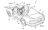
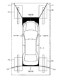
まず、図1および図2を用いて、第1実施形態による車両1の概略的な構成について説明する。図1は、第1実施形態による車両1の車室2aの一部が透視された状態を示した例示的な斜視図である。また、図2は、第1実施形態による車両1を示した例示的な平面図(鳥瞰図)である。
<First Embodiment>
First, a schematic configuration of the vehicle 1 according to the first embodiment will be described with reference to FIGS. 1 and 2. FIG. 1 is an exemplary perspective view showing a state in which a part of the
図1に示されるように、第1実施形態による車両1は、図示しない乗員(ユーザ)が乗車する車室2aを有している。車室2a内には、ユーザとしての運転者が座席2bから操作可能な状態で、操舵部4や、加速操作部5、制動操作部6、変速操作部7などが設けられている。
As shown in FIG. 1, the vehicle 1 according to the first embodiment has a
操舵部4は、ダッシュボード(インストルメントパネル)から突出したステアリングホイールである。加速操作部5は、運転者の足下に設けられたアクセルペダルである。制動操作部6は、運転者の足下に設けられたブレーキペダルである。変速操作部7は、センターコンソールから突出したシフトレバーである。 The steering unit 4 is a steering wheel protruding from the dashboard (instrument panel). The acceleration operation unit 5 is an accelerator pedal provided under the driver's feet. The braking operation unit 6 is a brake pedal provided under the driver's feet. The shifting operation unit 7 is a shift lever protruding from the center console.
車室2a内には、各種の画像を出力可能な表示装置(ディスプレイ)8と、各種の音を出力可能な音声出力装置9と、を有するモニタ装置11が設けられている。モニタ装置11は、車室2a内のダッシュボードの車幅方向(左右方向)の中央部に設けられている。表示装置8は、LCD(液晶ディスプレイ)やOELD(有機エレクトロルミネセンスディスプレイ)などで構成され、たとえば、車両1の周辺を撮像して得られた画像や、車両1を上から俯瞰で見たような画像などを表示可能に構成されている。車両1の周辺を撮像して得られた画像は、周辺画像などと称され、車両1を上から俯瞰で見たような画像は、俯瞰画像や鳥瞰画像などと称される。
In the
ここで、第1実施形態による表示装置8における画像が表示される領域、すなわち表示画面には、当該表示画面内において指やスタイラスなどの指示体が近接(接触を含む)した位置の座標を検出可能なタッチパネル10が設けられている。これにより、ユーザは、表示装置8の表示画面に表示される画像を視認することができるとともに、タッチパネル10上で指示体を用いた入力操作(たとえばタッチ操作)を行うことで、各種の操作を入力することができる。
Here, in the area where the image in the
なお、第1実施形態では、モニタ装置11が、スイッチや、ダイヤル、ジョイスティック、押しボタンなどといった、各種の物理的な操作入力部を有していてもよい。また、第1実施形態では、車室2a内におけるモニタ装置11の位置とは異なる位置に、他の音声出力装置が設けられていてもよい。この場合、音声出力装置9および他の音声出力装置の両方から、各種の音情報を出力することができる。また、第1実施形態では、モニタ装置11が、ナビゲーションシステムやオーディオシステムなどの各種システムに関する情報を表示可能に構成されていてもよい。
In the first embodiment, the monitoring device 11 may have various physical operation input units such as a switch, a dial, a joystick, and a push button. Further, in the first embodiment, another audio output device may be provided at a position different from the position of the monitoring device 11 in the
また、図1および図2に示されるように、第1実施形態による車両1は、左右2つの前輪3Fと、左右2つの後輪3Rと、を有した四輪の自動車である。前輪3Fの横滑り角は、操舵部4(ステアリングホイール)の操舵に応じて変化(転舵)する。なお、後述するように、第1実施形態による車両1には、前輪3Fの操舵を制御する操舵システム12(図3参照)が設けられている。操舵システム12は、電動パワーステアリングシステムや、SBW(ステアバイワイヤ)システムなどであり、不図示のアクチュエータによって操舵部4にトルク(アシストトルク)を付加して操舵力を補うことで、前輪3Fを操舵するシステムである。
Further, as shown in FIGS. 1 and 2, the vehicle 1 according to the first embodiment is a four-wheeled vehicle having two left and right
図2に示されるように、車両1(車体2)は、当該車両1の周囲の複数の領域を撮像可能に設けられた複数(図2の例では4つ)の車載カメラ16a、16b、16c、および16dを有している。車載カメラ16aは、車両1の前方の位置に設けられ、車載カメラ16bは、車両1の後方の位置に設けられ、車載カメラ16cは、車両1の車幅方向の左側の位置に設けられ、車載カメラ16dは、車両1の車幅方向の右側の位置に設けられている。これらの車載カメラ16a〜16dは、たとえば、CCD(電荷結合素子)やCIS(CMOS(相補性金属酸化膜半導体)イメージセンサ)などの撮像素子を有した、いわゆるデジタルカメラである。なお、以下では、簡単化のため、車載カメラ16a〜16dを総称して車載カメラ16と記載することがある。
As shown in FIG. 2, the vehicle 1 (vehicle body 2) has a plurality of (four in the example of FIG. 2) in-
車載カメラ16は、所定のフレームレートで車両1の周囲の領域を撮像し、当該撮像により得られた画像データを出力する。この画像データは、フレーム画像として動画像を構成することが可能である。また、車載カメラ16は、たとえば、水平方向に180〜220°の視野角の範囲を撮像可能な広角レンズを有する。
The in-
また、車載カメラ16a〜16dは、それぞれの光軸が車両1の下方に向くように設けられている。これにより、車載カメラ16a〜16dは、車両1が移動可能な路面と、当該路面から上方の領域(外部の環境)と、を撮像することが可能である。
Further, the in-
より具体的に、車載カメラ16aは、車体2の前側の端部2c(たとえばフロントグリル)に設けられ、車両1の前方の領域を撮像することが可能である。また、車載カメラ16bは、車体2の後側の端部2e(たとえばリアトランクのドア2h)に設けられ、車両1の後方の領域を撮像することが可能である。また、車載カメラ16cは、車体2の車幅方向の左側の端部2d(たとえば左側のドアミラー2g)に設けられ、車両1の左側の領域を撮像することが可能である。また、車載カメラ16dは、車体2の車幅方向の右側の端部2f(たとえば右側のドアミラー2g)に設けられ、車両1の右側の領域を撮像することが可能である。
More specifically, the in-
次に、図3を用いて、第1実施形態による車両1の内部の概略的なハードウェア構成について説明する。図3は、第1実施形態による車両1の内部の概略的なハードウェア構成を示した例示的なブロック図である。 Next, a schematic hardware configuration inside the vehicle 1 according to the first embodiment will be described with reference to FIG. FIG. 3 is an exemplary block diagram showing a schematic hardware configuration inside the vehicle 1 according to the first embodiment.
図3に示されるように、第1実施形態による車両1の内部には、モニタ装置11と、操舵システム12と、外部インターフェース(I/F)13と、ECU(エレクトロニックコントロールユニット)14と、ブレーキシステム18と、舵角センサ19と、アクセルセンサ20と、シフトセンサ21と、車輪速センサ22と、が設けられている。モニタ装置11と、操舵システム12と、外部インターフェース13と、ECU14と、ブレーキシステム18と、アクセルセンサ20と、シフトセンサ21と、車輪速センサ22とは、CAN(コントローラエリアネットワーク)などの電気通信回線(以下、車載ネットワーク23と記載する)を介して互いに通信可能に接続されている。
As shown in FIG. 3, inside the vehicle 1 according to the first embodiment, a monitoring device 11, a
ECU14は、車載カメラ16から得られた画像データに対して画像処理を実行し、当該画像処理によって得られた画像データを表示装置8に表示する。また、ECU14は、車載ネットワーク23を介して、車両1の各部へ制御信号を送信することで、操舵システム12やブレーキシステム18などの各部を制御する。この際、ECU14は、車載ネットワーク23を介して取得されるセンサデータ、すなわち、舵角センサ19、アクセルセンサ20、シフトセンサ21、車輪速センサ22などの検出結果(出力値)を、制御に利用することが可能である。また、ECU14は、車載ネットワーク23を介して取得される、タッチパネル10を用いた入力操作に関する情報も、制御に利用することが可能である。
The
ECU14は、CPU(中央演算処理装置)14aや、ROM(リードオンリーメモリ)14b、RAM(ランダムアクセスメモリ)14c、表示制御部14d、音声制御部14e、SSD(ソリッドステートドライブ)14fなどといったハードウェア構成を有している。
The
CPU14aは、車両1全体を制御する制御部である。CPU14aは、ROM14bやSSD14fなどの記憶装置に記憶されたプログラムを読み出し、当該プログラムに含まれる指令に従って動作することで、各種の処理を実行する。RAM14cは、たとえば、CPU14aが各種の処理を実行する際の作業領域として用いられる。
The
表示制御部14dは、表示装置8を介した画像出力を制御する。また、音声制御部14eは、音声出力装置9を介した音声出力を制御する。
The
なお、第1実施形態によるECU14において、CPU14a、ROM14bおよびRAM14cは、1つの集積回路に搭載されていてもよい。また、第1実施形態によるECU14では、車両1全体を制御する制御部として、CPU14aに替えて、DSP(デジタルシグナルプロセッサ)などのプロセッサや論理回路が設けられていてもよい。また、第1実施形態では、CPU14aにより実行されるプログラムなどを記憶する主記憶装置として、SSD14fに替えて(またはSSD14fに加えて)、HDD(ハードディスクドライブ)が設けられていてもよい。さらに、第1実施形態では、ECU14に接続される外部装置が、主記憶装置としてのSSD14fを有していてもよい。
In the
ところで、一般に、車両1の製造工程においては、各種の部品の組付工程の後に、当該各種の部品の検査工程が行われる。検査工程では、たとえば、車載カメラ16の撮像画像および当該撮像画像に基づいて生成される画像を用いた画像診断により、車載カメラ16が正常に動作しているか否かの検査が行われる。
By the way, in general, in the manufacturing process of the vehicle 1, the inspection process of the various parts is performed after the assembly process of the various parts. In the inspection step, for example, an image diagnosis using an image captured by the vehicle-mounted
上記のような画像診断には、たとえば、車載カメラ16a〜16dによる4枚の撮像画像に基づいて生成される、車両1を上方から見た俯瞰画像が用いられる。車載カメラ16a〜16dのうちの少なくとも1つに異常が存在する場合、俯瞰画像のうちの、車載カメラ16a〜16dによる4つの撮像領域の境界に対応した境界領域に写る対象物の表示ズレなどといった異常が表れる。このため、俯瞰画像を用いた画像診断では、検査員が俯瞰画像を目視で確認する必要がある。
For the above-mentioned image diagnosis, for example, a bird's-eye view image of the vehicle 1 viewed from above, which is generated based on four images captured by the in-
従来では、上記の俯瞰画像などを車両1の内部の表示装置8に表示させることで画像診断を行うことが一般的であった。しかしながら、このような画像診断の手法は、表示装置8が無い車両1には適用不可能である。
Conventionally, it has been common to perform image diagnosis by displaying the above-mentioned bird's-eye view image or the like on a
そこで、第1実施形態では、画像を表示可能な外部機器を接続するための外部インターフェース13を車載ネットワーク23上に設け、画像診断に用いる画像を車両から外部機器に車載ネットワーク23を介して転送することで、外部機器を用いて画像診断を行うことが可能な構成が適用される。
Therefore, in the first embodiment, an
以下、図4を参照して、画像診断に用いられる外部機器としての端末装置50についてより具体的に説明する。図4は、第1実施形態による画像診断に用いられる端末装置50の概略的なハードウェア構成を示した例示的なブロック図である。
Hereinafter, the
図4に示されるように、端末装置50は、ハードウェア構成として、接続インターフェース(I/F)51と、表示部52と、操作入力部53と、制御部54と、を有している。接続インターフェース51と、表示部52と、操作入力部53と、制御部54とは、バス55などを介して接続されている。
As shown in FIG. 4, the
接続インターフェース51は、車両1の外部インターフェース13に接続するためのインターフェースである。たとえば、接続インターフェース51と外部インターフェース13とは、通信ケーブルなどを介して接続される。表示部52は、画像を表示するためのデバイスである。表示部52は、車両1の表示装置8と同様に、LCDやOELDなどにより構成される。
The connection interface 51 is an interface for connecting to the
操作入力部53は、端末装置50に対する操作を入力するためのデバイスである。操作入力部53は、たとえば、表示部52に重ねて設けられるタッチパネルなどにより構成される。制御部54は、端末装置50の各部の動作を統括的に制御するデバイスである。制御部54は、プロセッサやメモリ(およびストレージ)などといった、通常のコンピュータと同様のハードウェア構成を有する。
The
ここで、端末装置50を用いた画像診断を行うためには、当該画像診断に用いられる画像、たとえば上述した俯瞰画像のような画像を、車両1(ECU14)から端末装置50に転送して表示部52に表示する必要がある。このような画像の転送は、車載ネットワーク23を介して行われる。
Here, in order to perform image diagnosis using the
しかしながら、車載ネットワーク23は、伝送速度が比較的遅いことが知られている。このため、たとえば画像診断に用いられる画像をそのままの形で転送すると、転送が完了するまでに時間がかかり、端末装置50を用いた画像診断の効率性が低下するおそれがある。
However, the in-
そこで、第1実施形態は、画像診断に用いる画像を転送するための車両1側の機能モジュール群である画像転送装置100と、画像診断に用いる画像を受信して表示するための端末装置50側の機能モジュール群である画像診断装置200と、を以下のように構成することで、画像診断の効率性が低下するのを抑制する。
Therefore, in the first embodiment, the
図5は、第1実施形態による画像転送装置100および画像診断装置200の機能的構成を示した例示的なブロック図である。第1実施形態では、図5に示された画像転送装置100および画像診断装置200により、車載カメラ16の異常を画像に基づいて診断する画像診断を行うための画像診断システムが構成される。以下では、車両1の外部インターフェース13と端末装置50の接続インターフェース51とが接続されることで、画像転送装置100と画像診断装置200とが互いに通信可能な状態になっているものとする。また、以下では、車両1を上方から見た俯瞰画像または当該俯瞰画像に基づく画像が、画像診断に用いられるものとする(詳細は後述する)。
FIG. 5 is an exemplary block diagram showing the functional configurations of the
図5に示されるように、画像転送装置100は、ECU14のCPU14aが所定のソフトウェア(コンピュータプログラム)を実行した結果としてECU14内に実現される機能モジュール群であり、画像診断装置200は、制御部54のプロセッサが所定のソフトウェアを実行した結果として制御部54内に実現される機能モジュール群である。なお、第1実施形態では、これらの機能モジュール群の一部または全部が専用のハードウェア(回路)によって実現されてもよい。
As shown in FIG. 5, the
より具体的に、画像転送装置100は、指示受信部101と、俯瞰画像取得部102と、診断画像抽出部103と、画像転送部104と、を有している。また、画像診断装置200は、入力受付部201と、指示出力部202と、画像受信部203と、表示処理部204と、を有している。
More specifically, the
画像診断装置200の入力受付部201は、操作入力部53を介して入力される検査員の操作入力を受け付ける。操作入力の例としては、画像診断に用いる画像の準備を画像転送装置100に指示する操作や、画像診断に用いる画像の転送を画像転送装置100に指示する操作などが挙げられる。画像診断装置200の指示出力部202は、入力受付部201が受け付けた操作入力に応じた指示を、車載ネットワーク23を介して画像転送装置100に出力する。
The
画像転送装置100の指示受信部101は、画像診断装置200の指示出力部202から出力された指示を受信する。画像転送装置100の俯瞰画像取得部102は、画像診断に用いる画像の準備を指示するために画像診断装置200から出力される画像準備指示が指示受信部101により受信されると、当該画像準備指示に従い、車載カメラ16a〜16dによる4枚の撮像画像に基づいて生成される俯瞰画像を取得する。このとき、俯瞰画像取得部102は、カラーの俯瞰画像をグレースケール化することで、データ量を削減してもよい。
The
ここで、第1実施形態において用いられる俯瞰画像について簡単に説明する。図6は、第1実施形態において用いられる俯瞰画像の一例を示した例示的な図である。 Here, the bird's-eye view image used in the first embodiment will be briefly described. FIG. 6 is an exemplary diagram showing an example of a bird's-eye view image used in the first embodiment.
図6に示されるように、俯瞰画像とは、車両1および当該車両1の周辺の領域を上方から見た画像である。俯瞰画像は、車両1の前後左右に設けられる車載カメラ16による4枚の撮像画像に視点変換や合成などといった種々の画像処理が施されることで生成される。
As shown in FIG. 6, the bird's-eye view image is an image of the vehicle 1 and the area around the vehicle 1 viewed from above. The bird's-eye view image is generated by performing various image processing such as viewpoint conversion and composition on four images captured by the in-
ここで、前述したように、車載カメラ16a〜16dのうちの少なくとも1つに異常が存在する場合、俯瞰画像のうちの、車載カメラ16a〜16dによる4つの撮像領域の境界に対応した境界領域に写る対象物の表示ズレなどといった異常が表れる。たとえば、図6の例では、車載カメラ16a〜16dのうちの少なくとも1つに異常が存在する場合、車両1の四隅から斜めに延びるラインL1〜L4を含む境界領域R1〜R4に写る対象物の表示ズレが発生する。
Here, as described above, when an abnormality is present in at least one of the in-
図6の例において、俯瞰画像の全体を目視で確認すれば、境界領域R1〜R4に写る対象物の表示ズレの有無を判定し、車載カメラ16a〜16dの異常の有無の診断ができることは言うまでもない。しかしながら、境界領域R1〜R4に写る対象物の表示ズレの有無は、俯瞰画像の全体を確認しなくても、境界領域R1〜R4のみを確認すれば、判定可能である。
Needless to say, in the example of FIG. 6, if the entire bird's-eye view image is visually confirmed, the presence or absence of display deviation of the object reflected in the boundary regions R1 to R4 can be determined, and the presence or absence of abnormality in the in-
そこで、図5に戻り、第1実施形態による画像転送装置100の診断画像抽出部103は、画像診断に用いる画像の転送を指示する画像転送指示が指示受信部101により受信されると、当該画像転送指示に応じて、俯瞰画像取得部102により取得された俯瞰画像の一部、つまり図6の例における境界領域R1〜R4の画像を、画像診断のための診断画像として抽出する(切り出す)。
Then, returning to FIG. 5, the diagnostic
そして、画像転送装置100の画像転送部104は、診断画像抽出部103により抽出された診断画像を、車載ネットワーク23を介して画像診断装置200に転送する。これにより、画像診断のために画像転送装置100から画像診断装置200に転送される画像のサイズが小さくなるので、転送が完了するまでにかかる時間を短縮し、画像診断の効率性を向上させることが可能になる。
Then, the
図7は、第1実施形態において俯瞰画像から部分的に抽出される診断画像の一例を示した例示的な図である。図7において、(a)の診断画像は、図6において車両1の左前方に位置する境界領域R1の画像であり、(b)の診断画像は、図6において車両1の右前方に位置する境界領域R2の画像である。また、図7において、(c)の診断画像は、図6において車両1の左後方に位置する境界領域R3の画像であり、(d)の診断画像は、図6において車両1の右後方に位置する境界領域R4の画像である。 FIG. 7 is an exemplary diagram showing an example of a diagnostic image partially extracted from the bird's-eye view image in the first embodiment. In FIG. 7, the diagnostic image of (a) is an image of the boundary region R1 located on the left front of the vehicle 1 in FIG. 6, and the diagnostic image of (b) is located on the right front of the vehicle 1 in FIG. It is an image of the boundary region R2. Further, in FIG. 7, the diagnostic image of (c) is an image of the boundary region R3 located at the left rear of the vehicle 1 in FIG. 6, and the diagnostic image of (d) is at the right rear of the vehicle 1 in FIG. It is an image of the boundary region R4 where it is located.
なお、第1実施形態は、画像転送装置100に転送させる画像を、俯瞰画像の一部の診断画像(図7参照)とするか、または全体の俯瞰画像(図6参照)とするかを、検査員が任意に選択可能な構成になっている。この選択は、たとえば、画像診断に用いる画像の転送を指示するために画像診断装置200から画像転送装置100に出力される画像転送指示に含められる。
In the first embodiment, it is determined whether the image to be transferred to the
したがって、図5に戻り、第1実施形態による画像転送装置100の画像転送部104は、画像転送指示が指示受信部101により受信されると、その画像転送指示に含まれる検査員の選択に応じて、俯瞰画像の一部の診断画像(図7参照)を転送するか、全体の俯瞰画像(図6参照)を転送するか、を切り替える。つまり、第1実施形態では、画像転送指示において、全体の俯瞰画像の転送が要求されている場合、画像転送装置100の診断画像抽出部103は、診断画像の抽出を実行せず、画像転送装置100の画像転送部104は、全体の俯瞰画像の転送を実行する。これにより、俯瞰画像の一部の診断画像を用いた画像診断と、全体の俯瞰画像を用いた画像診断と、を必要に応じて使い分けることができる。
Therefore, returning to FIG. 5, when the image transfer instruction is received by the
なお、画像診断装置200の画像受信部203は、画像転送装置100から転送された画像、つまり俯瞰画像の一部の診断画像(図7参照)または全体の俯瞰画像(図6参照)を受信する。また、画像診断装置200の表示処理部204は、画像受信部203により受信された画像を表示部52に表示する。これにより、検査員は、画像診断装置200の表示部52の表示画面を確認することで、境界領域R1〜R4に写る対象物の表示ズレの有無に基づいて、車載カメラ16の異常の有無を診断することができる。
The
以上の構成により、第1実施形態における画像診断時では、画像転送装置100および画像診断装置200が、以下のような流れで動作する。図8は、第1実施形態による画像転送装置100および画像診断装置200の画像診断時における動作の流れを示した例示的なシーケンス図である。
With the above configuration, at the time of image diagnosis in the first embodiment, the
図8に示されるように、第1実施形態における画像診断時では、まず、画像診断装置200が、画像診断に用いる画像の準備を画像転送装置100に指示する画像準備指示を、画像転送装置100に出力する(S1)。画像転送装置100は、画像準備指示を受信すると、当該画像準備指示に従い、俯瞰画像を取得する(S2)。そして、画像転送装置100は、俯瞰画像の取得が完了すると、準備完了の通知を画像診断装置200に出力する(S3)。
As shown in FIG. 8, at the time of image diagnosis in the first embodiment, first, the
画像診断装置200は、準備完了の通知を受信すると、画像診断に用いる画像の転送を画像転送装置100に指示する画像転送指示を、画像転送装置100に出力する(S4)。上述したように、画像転送指示には、転送対象の画像が俯瞰画像の一部の診断画像(図7参照)であるか、または全体の俯瞰画像(図6参照)であるかに関する検査員の選択が含まれる。
Upon receiving the notification of the completion of preparation, the image
画像転送装置100は、画像転送指示を受信すると、当該画像転送指示に含まれる検査員の選択に基づき、必要に応じて、全体の俯瞰画像(図6参照)から、当該俯瞰画像の一部の診断画像(図7参照)を抽出する(S5)。つまり、画像転送装置100は、画像転送指示で俯瞰画像の一部の診断画像の転送が要求されている場合は、診断画像の抽出を実行する一方、画像転送指示で全体の俯瞰画像の転送が要求されている場合は、診断画像の抽出を実行せずに、次の動作を実行する。
Upon receiving the image transfer instruction, the
画像転送装置100は、診断画像の抽出を実行した場合、抽出した診断画像を画像診断装置200に転送し、診断画像の抽出を実行しなかった場合、全体の俯瞰画像を画像診断装置200に転送する(S6)。そして、画像診断装置200は、俯瞰画像の一部の診断画像または全体の俯瞰画像を受信すると、受信した画像を表示部52に表示する(S7)。
When the diagnostic image is extracted, the
以上説明したように、第1実施形態による画像転送装置100は、車載カメラ16の撮像結果に基づく(画像診断のための)所定の画像としての俯瞰画像を取得する俯瞰画像取得部102と、車載ネットワーク23上に設けられる外部インターフェース13に画像診断装置200が接続された場合に、当該画像診断装置200からの指示に応じて、俯瞰画像から部分的に抽出された診断画像を画像診断装置200に車載ネットワーク23を介して転送する画像転送部104と、を有している。これにより、画像診断のために転送される診断画像のサイズが小さくなり、転送量が少なくなるので、伝送速度が比較的遅い車載ネットワークであっても、より迅速に診断画像を転送することができる。その結果、外部機器としての画像診断装置200を用いた画像診断の効率性が低下するのを抑制することができる。
As described above, the
また、第1実施形態による画像転送装置100において、画像転送部104は、俯瞰画像のうち、車載カメラ16a〜16dによる複数の撮像領域の境界に対応した境界領域の画像を、診断画像として転送する。これにより、俯瞰画像のうち、画像診断を行う必要がある境界領域の画像のみを、診断画像として転送することができるので、画像診断装置200を用いた画像診断の効率性を向上させることができる。
Further, in the
<第2実施形態>
上述した第1実施形態では、俯瞰画像から複数の診断画像が抽出された場合、抽出された全ての診断画像の転送が実行される。しかしながら、診断画像に異常が存在するか否かを転送前に判定し、異常が存在すると判定された診断画像のみを実際に転送するようにすれば、転送量をさらに削減することが可能になるとともに、検査員による確認の手間も低減することが可能になるので、画像診断の効率性が向上し、有意義である。
<Second Embodiment>
In the first embodiment described above, when a plurality of diagnostic images are extracted from the bird's-eye view image, all the extracted diagnostic images are transferred. However, if it is determined before transfer whether or not there is an abnormality in the diagnostic image and only the diagnostic image determined to have the abnormality is actually transferred, the transfer amount can be further reduced. At the same time, it is possible to reduce the time and effort required for confirmation by the inspector, which is meaningful because the efficiency of image diagnosis is improved.
そこで、以下では、第2実施形態として、診断画像が抽出された時点で当該診断画像に異常が存在するか否かを画像転送装置100a側で判定する画像診断システムについて説明する。
Therefore, in the following, as the second embodiment, an image diagnostic system for determining whether or not an abnormality exists in the diagnostic image at the time when the diagnostic image is extracted will be described on the
まず、第2実施形態による画像診断システムの構成について説明する。図9は、第2実施形態による画像転送装置100aおよび画像診断装置200の機能的構成を示した例示的なブロック図である。
First, the configuration of the diagnostic imaging system according to the second embodiment will be described. FIG. 9 is an exemplary block diagram showing the functional configurations of the
図9に示されるように、第2実施形態による画像転送装置100aは、指示受信部101と、俯瞰画像取得部102と、診断画像抽出部103と、画像転送部104aと、比較画像記憶部105aと、を有している。指示受信部101、俯瞰画像取得部102、および診断画像抽出部103については、上述した第1実施形態(図5参照)と同様であるため、以下では画像転送部104aおよび比較画像記憶部105aについてのみ説明する。また、画像診断装置200についても、上述した第1実施形態と同様であるため、以下では、画像診断装置200についての詳細な説明を省略する。
As shown in FIG. 9, the
第2実施形態による画像転送装置100aの画像転送部104aは、画像診断装置200からの画像転送指示に応じて俯瞰画像の一部の複数の診断画像(図7参照)を転送する場合、それら複数の診断画像のうち、比較画像記憶部105aに記憶された比較画像と一致しない診断画像のみを、画像診断装置200に転送する。なお、比較画像とは、車載カメラ16に異常がない状態での境界領域を表す画像、つまり対象物の表示ズレがない診断画像のことである。このような比較画像は、比較画像記憶部105aに予め記憶されているものとする。
When the image transfer unit 104a of the
より具体的に、第2実施形態による画像転送部104aは、診断画像抽出部103により複数の診断画像(図7参照)が抽出された場合、まず、それら複数の診断画像と比較画像とが一致するか否かを判定することで、比較画像と一致しない診断画像を特定する。
More specifically, in the image transfer unit 104a according to the second embodiment, when a plurality of diagnostic images (see FIG. 7) are extracted by the diagnostic
ここで、比較画像と一致しない診断画像は、異常な診断画像、つまり異常を含む車載カメラ16の撮像結果に基づいて生成された診断画像であると言えるため、画像診断の対象とする必要がある。一方、比較画像と一致する診断画像は、異常がない診断画像、つまり異常を含まない車載カメラ16の撮像結果に基づいて生成された診断画像であると言えるため、画像診断の対象とする必要はない。
Here, the diagnostic image that does not match the comparative image can be said to be an abnormal diagnostic image, that is, a diagnostic image generated based on the imaging result of the in-
したがって、第2実施形態による画像転送部104aは、上記の判定結果に基づいて、比較画像と一致しない診断画像のみを、画像診断装置200に転送する。これにより、第2実施形態によれば、転送量をさらに削減することが可能になるとともに、検査員による確認の手間も低減することが可能になるので、画像診断の効率性が向上する。
Therefore, the image transfer unit 104a according to the second embodiment transfers only the diagnostic image that does not match the comparative image to the
なお、第2実施形態のその他の構成は、上述した第1実施形態と同様であるため、ここでは説明を省略する。 Since the other configurations of the second embodiment are the same as those of the first embodiment described above, the description thereof will be omitted here.
次に、第2実施形態において実行される動作の流れについて説明する。図10は、第2実施形態による画像転送装置100aおよび画像診断装置200の画像診断時における動作の流れを示した例示的なシーケンス図である。
Next, the flow of the operation executed in the second embodiment will be described. FIG. 10 is an exemplary sequence diagram showing an operation flow at the time of image diagnosis of the
図10に示されるように、第2実施形態における画像診断時には、画像診断装置200による画像準備指示の出力(S11)と、画像転送装置100aによる俯瞰画像の取得(S12)と、画像転送装置100aによる準備完了の通知の出力(S13)と、画像診断装置200による画像転送指示の出力(S14)と、画像転送装置100aによる診断画像の抽出(S15)と、がこの順番で実行される。なお、S11〜S15までの動作の流れは、図8に示された第1実施形態におけるS1〜S5までの動作の流れと同様であるため、ここではこれ以上の説明を省略する。また、以下では、簡単化のため、S14の画像転送指示において、全体の俯瞰画像の転送が要求されていないものとする。
As shown in FIG. 10, at the time of image diagnosis in the second embodiment, the
画像転送装置100aは、診断画像の抽出を実行した場合、抽出した診断画像と、比較画像記憶部105aに記憶された比較画像と、を比較し、比較結果に基づいて、比較画像と一致しない診断画像を、異常な診断画像として特定する(S16)。そして、画像転送装置100aは、特定した異常な診断画像のみを、画像診断装置200に転送する(S17)。そして、画像診断装置200は、異常な画像を受信すると、受信した異常な画像を表示部52に表示する(S18)。
When the diagnostic image is extracted, the
以上説明したように、第2実施形態において、画像転送装置100aは、車載カメラ16a〜16dに異常がない状態での境界領域を表す比較画像を記憶する比較画像記憶部105aを有しており、画像転送部104aは、比較画像と一致しない診断画像を、車載ネットワーク23を介して画像診断装置200に転送する。これにより、比較画像と一致しない診断画像、つまり画像診断を行う必要がある診断画像のみを画像診断装置200に転送することができるので、画像診断装置200を用いた画像診断の効率性を向上させることができる。
As described above, in the second embodiment, the
なお、第2実施形態のその他の効果は、上述した第1実施形態と同様である。 The other effects of the second embodiment are the same as those of the first embodiment described above.
<第2実施形態の変形例>
上述した第2実施形態では、診断画像に異常が存在するか否かの判定を、画像の転送前に、画像を転送する側で実行する例について説明した。しかしながら、診断画像に異常が存在するか否かの判定は、診断画像の転送後に、診断画像を受信した側で実行することも可能である。
<Modified example of the second embodiment>
In the second embodiment described above, an example has been described in which the determination of whether or not an abnormality is present in the diagnostic image is executed on the side that transfers the image before the image is transferred. However, it is also possible to determine whether or not there is an abnormality in the diagnostic image on the side receiving the diagnostic image after the diagnostic image is transferred.
そこで、以下では、第2実施形態の変形例として、診断画像に異常が存在するか否かの判定を、診断画像の転送後に、診断画像を受信した画像診断装置200a側で実行する例について説明する。
Therefore, in the following, as a modified example of the second embodiment, an example in which determination of whether or not an abnormality exists in the diagnostic image is executed on the image
まず、第2実施形態の変形例による画像診断システムの構成について説明する。図11は、第2実施形態の変形例による画像転送装置100および画像診断装置200aの機能的構成を示した例示的なブロック図である。
First, the configuration of the diagnostic imaging system according to the modified example of the second embodiment will be described. FIG. 11 is an exemplary block diagram showing the functional configurations of the
図11に示されるように、第2実施形態の変形例による画像診断装置200aは、入力受付部201と、指示出力部202と、画像受信部203と、表示処理部204aと、比較画像記憶部205aと、を有している。入力受付部201、指示出力部202、および画像受信部203については、上述した第2実施形態(図9参照)と同様であるため、以下では表示処理部204aおよび比較画像記憶部205aについてのみ説明する。また、画像転送装置100については、上述した第1実施形態(図5参照)と同様であるため、以下では、画像転送装置100についての詳細な説明を省略する。
As shown in FIG. 11, the image
第2実施形態の変形例による画像診断装置200aの表示処理部204aは、画像受信部203により複数の診断画像(図7参照)が受信された場合、それら複数の診断画像のうち、比較画像記憶部205aに記憶された比較画像と一致しない診断画像のみを、表示部52(図4参照)に表示する。ここで言及している比較画像とは、上述した第2実施形態と同様の、車載カメラ16に異常がない状態での境界領域を表す画像、つまり対象物の表示ズレがない診断画像のことである。このような比較画像は、比較画像記憶部205aに予め記憶されているものとする。
When a plurality of diagnostic images (see FIG. 7) are received by the
より具体的に、第2実施形態の変形例による表示処理部204aは、画像受信部203により複数の診断画像(図7参照)が受信された場合、まず、それら複数の診断画像と比較画像とが一致するか否かを判定することで、比較画像と一致しない診断画像を特定する。
More specifically, when a plurality of diagnostic images (see FIG. 7) are received by the
上述した第2実施形態と同様に、比較画像と一致しない診断画像は、異常な診断画像、つまり異常を含む車載カメラ16の撮像結果に基づいて生成された診断画像であると言えるため、画像診断の対象とする必要がある。一方、比較画像と一致する診断画像は、異常がない診断画像、つまり異常を含まない車載カメラ16の撮像結果に基づいて生成された診断画像であると言えるため、画像診断の対象とする必要はない。
Similar to the second embodiment described above, the diagnostic image that does not match the comparative image can be said to be an abnormal diagnostic image, that is, a diagnostic image generated based on the imaging result of the in-
したがって、第2実施形態の変形例による表示処理部204aは、上述した判定結果に基づいて、比較画像と一致しない診断画像のみを、表示部52(図4参照)に表示する。これにより、第2実施形態の変形例によれば、検査員に異常な診断画像のみを確認させることができるので、画像診断の効率性を向上させることができる。
Therefore, the
なお、第2実施形態の変形例のその他の構成は、上述した第2実施形態と同様であるため、ここでは説明を省略する。 Since the other configurations of the modified examples of the second embodiment are the same as those of the second embodiment described above, the description thereof will be omitted here.
次に、第2実施形態の変形例において実行される動作の流れについて説明する。図12は、第2実施形態の変形例による画像転送装置100および画像診断装置200aの画像診断時における動作の流れを示した例示的なシーケンス図である。
Next, the flow of the operation executed in the modified example of the second embodiment will be described. FIG. 12 is an exemplary sequence diagram showing an operation flow at the time of image diagnosis of the
図12に示されるように、第2実施形態の変形例における画像診断時には、画像診断装置200aによる画像準備指示の出力(S21)と、画像転送装置100による俯瞰画像の取得(S22)と、画像転送装置100による準備完了の通知の出力(S23)と、画像診断装置200aによる画像転送指示の出力(S24)と、画像転送装置100による診断画像の抽出(S25)と、がこの順番で実行される。なお、S21〜S25までの動作の流れは、図10に示された第2実施形態におけるS11〜S15までの動作の流れと同様であるため、ここではこれ以上の説明を省略する。
As shown in FIG. 12, at the time of image diagnosis in the modified example of the second embodiment, the
画像転送装置100は、診断画像の抽出を実行した場合、抽出した全ての診断画像を、画像診断装置200aに転送する(S26)。そして、画像診断装置200aは、受信した診断画像と、比較画像記憶部205aに記憶された比較画像と、を比較し、比較結果に基づいて、比較画像と一致しない診断画像を、異常な診断画像として特定する(S27)。そして、画像診断装置200aは、特定した異常な診断画像のみを、表示部52に表示する(S28)。
When the diagnostic image is extracted, the
以上説明したように、第2実施形態の変形例において、画像診断装置200aは、車載カメラ16a〜16dに異常がない状態での境界領域を表す比較画像を記憶する比較画像記憶部205aを有しており、表示処理部204aは、画像受信部203が受信した診断画像のうち、比較画像と一致しない診断画像を表示部52に表示する。これにより、比較画像と一致しない診断画像、つまり画像診断を行う必要がある診断画像のみを、表示部52に表示することができるので、画像診断の効率性を向上させることができる。
As described above, in the modified example of the second embodiment, the
<第3実施形態>
上述した第1実施形態、第2実施形態およびその変形例では、車両1を上方から見た俯瞰画像から診断画像を抽出する例について説明した。しかしながら、診断画像は、俯瞰画像から抽出される画像に限られるものではない。
<Third Embodiment>
In the first embodiment, the second embodiment, and the modified examples described above, an example of extracting a diagnostic image from a bird's-eye view image of the vehicle 1 viewed from above has been described. However, the diagnostic image is not limited to the image extracted from the bird's-eye view image.
そこで、以下では、第3実施形態として、光軸調整などといった車載カメラ16の校正の指標として設けられるマーカM(後述の図14参照)の撮像画像であるマーカ画像から診断画像を抽出する画像診断システムについて説明する。
Therefore, in the following, as a third embodiment, image diagnosis is performed by extracting a diagnostic image from a marker image which is an image captured by a marker M (see FIG. 14 described later) provided as an index for calibration of the in-
まず、第3実施形態による画像診断システムの構成について説明する。図13は、第3実施形態による画像転送装置100bおよび画像診断装置200において実現される機能的構成を示した例示的なブロック図である。
First, the configuration of the diagnostic imaging system according to the third embodiment will be described. FIG. 13 is an exemplary block diagram showing a functional configuration realized in the
図13に示されるように、第3実施形態による画像転送装置100bは、指示受信部101と、マーカ画像取得部102bと、マーカ異常判定部106bと、診断画像抽出部103bと、画像転送部104bと、を有している。指示受信部101については、上述した第1実施形態(図5参照)と同様であるため、以下では、マーカ画像取得部102b、マーカ異常判定部106b、診断画像抽出部103b、および画像転送部104bについてのみ説明する。また、画像診断装置200については、上述した第1実施形態(図5参照)と同様であるため、以下では、画像診断装置200についての詳細な説明を省略する。
As shown in FIG. 13, the
マーカ画像取得部102bは、画像診断装置200からの画像準備指示が指示受信部101により受信された場合に、マーカ画像を取得する。このとき、マーカ画像取得部102bは、マーカ画像に2値化処理などを施すことで、マーカ画像のデータ量を削減してもよい。ここで、マーカ画像とは、検査のために停車中の車両1の周囲に設けられるマーカMを車載カメラ16で撮像した画像のことである。詳細は後述するが、第3実施形態では、マーカ画像に基づいて生成される画像が、画像診断の対象となる。
The marker
図14は、第3実施形態による画像診断で用いられるマーカMを示した模式的かつ例示的な図である。図14に示されるように、マーカMは、車両1の周囲に、各車載カメラ16に対して2つずつ対応するように設置される。図14の例において、マーカMは、複数の円形の印Sを含んでいる。なお、図14に示されたマーカMの個数および配置は、あくまで一例であって、マーカMの個数および配置は、図14に示された例に限られるものではない。
FIG. 14 is a schematic and exemplary diagram showing the marker M used in the diagnostic imaging according to the third embodiment. As shown in FIG. 14, two markers M are installed around the vehicle 1 so as to correspond to each in-
図13に戻り、マーカ異常判定部106bは、マーカ画像取得部102bにより取得されたマーカ画像から、マーカMが正常に検出されるか否かを判定する。たとえば、マーカ画像に写っているマーカM内の円形の印Sの個数が実際のものと異なる状態である場合、マーカ異常判定部106bは、当該マーカ画像からマーカMが正常に検出されない、つまりマーカ画像が何らかの異常を含んでいると判断する。このようなマーカ画像の異常は、車載カメラ16の光軸などに異常がある場合に発生しうる。
Returning to FIG. 13, the marker
ところで、上記のようなマーカ画像の異常は、画像処理などによって検出することが可能である。しかしながら、検出された異常が、具体的にどのような要因で発生したものなのかは、画像処理では分からない。たとえば、検出された異常が、マーカMの周辺の照度が原因で発生したものなのか、よごれが原因で発生したものなのか、障害物が原因で発生したものなのかなどは、マーカ画像における異常に該当する部分を検査員に目視で確認させる画像診断を行わなければ分からない。 By the way, the above-mentioned abnormality of the marker image can be detected by image processing or the like. However, it is not possible to know by image processing what kind of factor the detected abnormality was caused by. For example, whether the detected abnormality is caused by the illuminance around the marker M, is caused by dirt, or is caused by an obstacle, etc., is an abnormality in the marker image. It is not possible to know unless an image diagnosis is performed so that the inspector visually confirms the part corresponding to.
一方、前述したように、車載ネットワーク23は、伝送速度が比較的遅いことが知られている。このため、検査員による画像診断の効率性を考慮すると、マーカ画像の全体を画像転送装置100bから画像診断装置200に転送するのではなく、マーカ画像における異常に該当する部分のみを画像転送装置100bから画像診断装置200に転送することが望ましい。
On the other hand, as described above, the in-
そこで、第3実施形態による診断画像抽出部103bは、マーカ異常判定部106bの判定結果に応じて、マーカMが正常に検出されなかったマーカ画像から、画像診断のための診断画像を部分的に抽出する。より具体的に、診断画像抽出部103bは、マーカMが正常に検出されなかったマーカ画像のうち、マーカMの設置位置を含む所定の範囲に対応した所定の領域の画像を、診断画像として抽出する。
Therefore, the diagnostic
図15は、第3実施形態においてマーカ画像から部分的に抽出される診断画像の一例を示した例示的な図である。図15に示されるように、第3実施形態による診断画像は、車両1の周辺に設置されたマーカMを車載カメラ16で撮像することで得られたマーカ画像のうち、マーカMが写った部分を、その周辺の領域とともに切り出したものである。マーカMの設置位置は、予め決まっているため、マーカ画像を切り出す範囲は、マーカMの設置位置に応じて予め決まっている。したがって、第3実施形態では、マーカ画像を切り出す範囲が、ROI(Region Of Interest)として予め記憶されているものとする。
FIG. 15 is an exemplary diagram showing an example of a diagnostic image partially extracted from a marker image in the third embodiment. As shown in FIG. 15, the diagnostic image according to the third embodiment is a portion of the marker image obtained by capturing the marker M installed around the vehicle 1 with the in-
図13に戻り、画像転送部104bは、診断画像抽出部103bにより診断画像が抽出された場合、抽出された診断画像を、画像診断装置200に転送する。このとき、画像転送部104bは、診断画像にデータ圧縮を施してもよい。これにより、診断画像のデータ量が削減されるので、伝送速度が比較的遅い車載ネットワーク23であっても、より迅速に診断画像を転送することができ、画像診断の効率性が低下するのを抑制することができる。
Returning to FIG. 13, when the diagnostic image is extracted by the diagnostic
なお、第3実施形態のその他の構成は、上述した第1実施形態と同様であるため、ここでは説明を省略する。 Since the other configurations of the third embodiment are the same as those of the first embodiment described above, the description thereof will be omitted here.
次に、第3実施形態において実行される動作の流れについて説明する。図16は、第3実施形態による画像転送装置100bおよび画像診断装置200の画像診断時における動作の流れを示した例示的なシーケンス図である。
Next, the flow of the operation executed in the third embodiment will be described. FIG. 16 is an exemplary sequence diagram showing an operation flow at the time of image diagnosis of the
図16に示されるように、第3実施形態における画像診断時では、まず、画像診断装置200が、画像診断に用いる画像の準備を画像転送装置100bに指示する画像準備指示を、画像転送装置100bに出力する(S31)。画像転送装置100bは、画像準備指示を受信すると、当該画像準備指示に従い、マーカ画像を取得する(S32)。そして、画像転送装置100bは、マーカ画像からマーカMが正常に検出されるか否かを、画像処理などによって判定する(S33)。判定が終了すると、画像転送装置100bは、準備完了の通知を画像診断装置200に出力する(S34)。
As shown in FIG. 16, at the time of image diagnosis in the third embodiment, first, the
画像診断装置200は、準備完了の通知を受信すると、画像診断に用いる画像の転送を画像転送装置100bに要求する画像転送指示を、画像転送装置100bに出力する(S35)。そして、画像転送装置100bは、画像転送指示を受信すると、マーカ画像から、ROIとして予め設定された領域を切り出すことで、マーカ画像の一部の、マーカMが写った診断画像を抽出する(S36)。
Upon receiving the notification of the completion of preparation, the image
そして、画像転送装置100bは、抽出した診断画像を、車載ネットワーク23を介して画像診断装置200に転送する(S37)。そして、画像診断装置200は、診断画像を受信すると、受信した診断画像を、表示部52に表示する(S38)。
Then, the
以上説明したように、第3実施形態による画像転送装置100bにおいて、マーカ画像取得部102bは、車両1の周辺の所定の位置に設置されたマーカMの車載カメラ16による撮像画像であるマーカ画像を、画像診断を行うための所定の画像として取得する。そして、画像転送装置100bの画像転送部104bは、マーカ異常判定部106bの判定結果に応じて、マーカMが正常に検出されなかったマーカ画像のうち、マーカMの設置位置を含む所定の範囲に対応した所定の領域の画像を、診断画像として転送する。これにより、マーカ画像のうち、画像診断を行う必要がある所定の領域の画像のみを、診断画像として転送することができる。
As described above, in the
なお、第3実施形態のその他の効果は、上述した第1実施形態と同様である。 The other effects of the third embodiment are the same as those of the first embodiment described above.
以上、本発明のいくつかの実施形態および変形例を説明したが、上述した実施形態および変形例はあくまで一例であって、発明の範囲を限定することは意図していない。上述した新規な実施形態および変形例は、様々な形態で実施されることが可能であり、発明の要旨を逸脱しない範囲で、種々の省略、置き換え、変更を行うことができる。上述した実施形態および変形例は、発明の範囲や要旨に含まれるとともに、特許請求の範囲に記載された発明とその均等の範囲に含まれる。 Although some embodiments and modifications of the present invention have been described above, the above-described embodiments and modifications are merely examples, and the scope of the invention is not intended to be limited. The novel embodiments and modifications described above can be implemented in various forms, and various omissions, replacements, and changes can be made without departing from the gist of the invention. The above-described embodiments and modifications are included in the scope and gist of the invention, and are included in the scope of the invention described in the claims and the equivalent scope thereof.
1 車両
13 外部インターフェース
16、16a〜16d 車載カメラ
23 車載ネットワーク
100、100a、100b 画像転送装置
102 俯瞰画像取得部(画像取得部)
102b マーカ画像取得部(画像取得部)
104、104a、104b 画像転送部
105a 比較画像記憶部(記憶部)
106b マーカ異常判定部(判定部)
200、200a 画像診断装置
201 入力受付部
202 指示出力部
203 画像受信部
204、204a 表示処理部
205a 比較画像記憶部(記憶部)
1
102b Marker image acquisition unit (image acquisition unit)
104, 104a, 104b Image transfer unit 105a Comparative image storage unit (storage unit)
106b Marker abnormality judgment unit (judgment unit)
200, 200a Image
Claims (8)
前記車載カメラの異常を画像に基づいて診断する画像診断装置が、車載ネットワーク上に設けられる前記車両の外部インターフェースに接続された場合に、前記画像診断装置からの指示に応じて、前記所定の画像から部分的に抽出された診断画像を、前記車載ネットワークを介して前記画像診断装置に転送する画像転送部と、
を備える、画像転送装置。 An image acquisition unit that acquires a predetermined image based on the imaging result of an in-vehicle camera that images the surroundings of the vehicle,
When the diagnostic imaging device that diagnoses an abnormality of the vehicle-mounted camera based on an image is connected to the external interface of the vehicle provided on the vehicle-mounted network, the predetermined image is in response to an instruction from the diagnostic imaging device. An image transfer unit that transfers a diagnostic image partially extracted from the image to the diagnostic imaging apparatus via the vehicle-mounted network, and an image transfer unit.
An image transfer device.
前記画像転送部は、前記俯瞰画像のうち、前記複数の車載カメラによる複数の撮像領域の境界に対応した境界領域の画像を、前記診断画像として転送する、
請求項1に記載の画像転送装置。 The image acquisition unit uses a bird's-eye view image of the periphery of the vehicle as a predetermined image, which is generated based on the imaging results of the plurality of vehicle-mounted cameras when a plurality of the vehicle-mounted cameras are provided. Acquired,
The image transfer unit transfers an image of the boundary region corresponding to the boundary of a plurality of imaging regions by the plurality of vehicle-mounted cameras from the bird's-eye view image as the diagnostic image.
The image transfer device according to claim 1.
前記画像転送部は、前記比較画像と一致しない前記診断画像を、前記車載ネットワークを介して前記画像診断装置に転送する、
請求項2に記載の画像転送装置。 Further, a storage unit for storing a comparative image representing the boundary region in a state where the plurality of in-vehicle cameras are normal is provided.
The image transfer unit transfers the diagnostic image that does not match the comparative image to the diagnostic imaging device via the vehicle-mounted network.
The image transfer device according to claim 2.
前記撮像画像から前記マーカが正常に検出されるか否かを判定する判定部をさらに備え、
前記画像転送部は、前記判定部の判定結果に応じて、前記マーカが正常に検出されなかった前記撮像画像のうち、前記マーカの設置位置を含む所定の範囲に対応した所定の領域の画像を、前記診断画像として転送する、
請求項1に記載の画像転送装置。 The image acquisition unit uses a captured image of a marker installed at a predetermined position around the vehicle, which is captured by the plurality of vehicle-mounted cameras when a plurality of the vehicle-mounted cameras are provided, as the predetermined image. Acquired,
A determination unit for determining whether or not the marker is normally detected from the captured image is further provided.
The image transfer unit captures an image of a predetermined region corresponding to a predetermined range including the installation position of the marker among the captured images in which the marker is not normally detected according to the determination result of the determination unit. , Transfer as the diagnostic image,
The image transfer device according to claim 1.
請求項1〜4のいずれか1項に記載の画像転送装置。 The image transfer unit switches between transferring the diagnostic image or transferring the entire predetermined image in response to the instruction from the diagnostic imaging apparatus.
The image transfer device according to any one of claims 1 to 4.
操作入力を受け付ける入力受付部と、
前記画像診断装置が前記外部インターフェースに接続された状態で、前記車両の画像転送装置であって、前記車載カメラの撮像結果に基づく所定の画像を取得する画像取得部と、前記画像診断装置が前記外部インターフェースに接続された場合に、前記画像診断装置からの指示に応じて、前記所定の画像から部分的に抽出された診断画像を、前記車載ネットワークを介して前記画像診断装置に転送する画像転送部と、を備えた画像転送装置に、前記操作入力に対応した指示を出力する指示出力部と、
前記指示に応じて前記画像転送装置から転送された前記診断画像を受信する画像受信部と、
前記画像受信部により受信された前記診断画像を表示部に表示する表示処理部と、
を備える、画像診断装置。 An image diagnostic device that is configured to be connectable to an external interface of a vehicle provided on an in-vehicle network and diagnoses an abnormality of an in-vehicle camera that images the surroundings of the vehicle based on the image.
An input reception unit that accepts operation input and
With the image diagnostic device connected to the external interface, the image transfer device of the vehicle, the image acquisition unit that acquires a predetermined image based on the image pickup result of the vehicle-mounted camera, and the image diagnostic device are said to be the same. Image transfer that, when connected to an external interface, transfers a diagnostic image partially extracted from the predetermined image to the diagnostic imaging device via the vehicle-mounted network in response to an instruction from the diagnostic imaging device. An instruction output unit that outputs an instruction corresponding to the operation input to an image transfer device including the unit.
An image receiving unit that receives the diagnostic image transferred from the image transfer device in response to the instruction.
A display processing unit that displays the diagnostic image received by the image receiving unit on the display unit, and
A diagnostic imaging device.
前記診断画像は、前記俯瞰画像のうち、前記複数の車載カメラによる複数の撮像領域の境界に対応した境界領域の画像であり、
前記複数の車載カメラに異常がない状態での前記境界領域を表す比較画像を記憶する記憶部をさらに備え、
前記表示処理部は、前記画像受信部が受信した前記診断画像のうち、前記比較画像と一致しない前記診断画像を前記表示部に表示する、
請求項6に記載の画像診断装置。 The predetermined image is a bird's-eye view image of the periphery of the vehicle viewed from above, which is generated based on the imaging results of the plurality of vehicle-mounted cameras when a plurality of the vehicle-mounted cameras are provided.
The diagnostic image is an image of a boundary region corresponding to the boundary of a plurality of imaging regions by the plurality of vehicle-mounted cameras in the bird's-eye view image.
Further, a storage unit for storing a comparative image representing the boundary region in a state where the plurality of in-vehicle cameras are normal is provided.
Among the diagnostic images received by the image receiving unit, the display processing unit displays the diagnostic image that does not match the comparative image on the display unit.
The diagnostic imaging apparatus according to claim 6.
車載ネットワーク上に設けられる前記車両の外部インターフェースに接続可能に構成され、前記車両の周辺を撮像する車載カメラの異常を画像に基づいて診断する画像診断装置と、
を備え、
前記画像転送装置は、
前記車載カメラの撮像結果に基づく所定の画像を取得する画像取得部と、
前記画像診断装置が前記外部インターフェースに接続された場合に、前記画像診断装置からの指示に応じて、前記所定の画像から部分的に抽出された診断画像を、前記車載ネットワークを介して前記画像診断装置に転送する画像転送部と、
を含み、
前記画像診断装置は、
操作入力を受け付ける入力受付部と、
前記画像診断装置が前記外部インターフェースに接続された状態で、前記操作入力に対応した前記指示を、前記画像転送装置に出力する指示出力部と、
前記指示に応じて前記画像転送装置から転送された前記診断画像を表示部に表示する表示処理部と、
を含む、画像診断システム。 The image transfer device installed in the vehicle and
An image diagnostic device that is configured to be connectable to the external interface of the vehicle provided on the vehicle network and that diagnoses an abnormality of the vehicle camera that images the surroundings of the vehicle based on the image.
With
The image transfer device is
An image acquisition unit that acquires a predetermined image based on the image pickup result of the in-vehicle camera, and an image acquisition unit.
When the diagnostic imaging device is connected to the external interface, the diagnostic image partially extracted from the predetermined image is subjected to the diagnostic imaging via the vehicle-mounted network in response to an instruction from the diagnostic imaging device. The image transfer unit that transfers to the device and
Including
The diagnostic imaging device
An input reception unit that accepts operation input and
An instruction output unit that outputs the instruction corresponding to the operation input to the image transfer device while the image diagnostic device is connected to the external interface.
A display processing unit that displays the diagnostic image transferred from the image transfer device on the display unit in response to the instruction.
Diagnostic imaging system, including.
Priority Applications (2)
| Application Number | Priority Date | Filing Date | Title |
|---|---|---|---|
| JP2017114593A JP6855331B2 (en) | 2017-06-09 | 2017-06-09 | Image transfer device, diagnostic imaging device, and diagnostic imaging system |
| CN201810569394.0A CN109068091A (en) | 2017-06-09 | 2018-06-05 | Image transfer apparatus, image diagnosing system and image diagnostic system |
Applications Claiming Priority (1)
| Application Number | Priority Date | Filing Date | Title |
|---|---|---|---|
| JP2017114593A JP6855331B2 (en) | 2017-06-09 | 2017-06-09 | Image transfer device, diagnostic imaging device, and diagnostic imaging system |
Publications (2)
| Publication Number | Publication Date |
|---|---|
| JP2018207458A JP2018207458A (en) | 2018-12-27 |
| JP6855331B2 true JP6855331B2 (en) | 2021-04-07 |
Family
ID=64820371
Family Applications (1)
| Application Number | Title | Priority Date | Filing Date |
|---|---|---|---|
| JP2017114593A Active JP6855331B2 (en) | 2017-06-09 | 2017-06-09 | Image transfer device, diagnostic imaging device, and diagnostic imaging system |
Country Status (2)
| Country | Link |
|---|---|
| JP (1) | JP6855331B2 (en) |
| CN (1) | CN109068091A (en) |
Families Citing this family (2)
| Publication number | Priority date | Publication date | Assignee | Title |
|---|---|---|---|---|
| JP7202195B2 (en) * | 2019-01-23 | 2023-01-11 | 本田技研工業株式会社 | DISPLAY SYSTEM, RUNNING CONTROL DEVICE, DISPLAY CONTROL METHOD AND PROGRAM |
| US20220130185A1 (en) * | 2020-10-23 | 2022-04-28 | Argo AI, LLC | Enhanced sensor health and regression testing for vehicles |
Family Cites Families (10)
| Publication number | Priority date | Publication date | Assignee | Title |
|---|---|---|---|---|
| DE112008004272A5 (en) * | 2007-02-16 | 2013-10-24 | Sumitomo Wiring Systems, Ltd. | A VIDEO COMMUNICATION SYSTEM BUILT INTO A VEHICLE AND A PICTURE RECORDING SYSTEM INSTALLED IN A VEHICLE |
| JP5592138B2 (en) * | 2010-03-31 | 2014-09-17 | 富士通テン株式会社 | Image generation apparatus, image display system, and image generation method |
| DE102011077143A1 (en) * | 2011-06-07 | 2012-12-13 | Robert Bosch Gmbh | A vehicle camera system and method for providing a seamless image of the vehicle environment |
| US9013579B2 (en) * | 2011-06-16 | 2015-04-21 | Aisin Seiki Kabushiki Kaisha | Vehicle surrounding-area monitoring apparatus |
| CN102387349B (en) * | 2011-10-31 | 2014-12-10 | 深圳市长宇电器有限公司 | Method and device for displaying images acquired by on-vehicle cameras |
| US9387813B1 (en) * | 2012-03-21 | 2016-07-12 | Road-Iq, Llc | Device, system and method for aggregating networks and serving data from those networks to computers |
| JP2014011785A (en) * | 2012-07-03 | 2014-01-20 | Clarion Co Ltd | Diagnostic device and diagnostic method for on-vehicle camera contamination removal apparatus, and vehicle system |
| CN103676922B (en) * | 2012-09-07 | 2016-12-21 | 博世汽车服务技术(苏州)有限公司 | A kind of method of long-range diagnosis |
| JP6422077B2 (en) * | 2014-09-30 | 2018-11-14 | 株式会社日本総合研究所 | Overhead image display system, terminal device, and program thereof |
| JP6453645B2 (en) * | 2014-12-25 | 2019-01-16 | 京セラ株式会社 | Stereo camera device, moving object, stereo camera system, server device, and control method |
-
2017
- 2017-06-09 JP JP2017114593A patent/JP6855331B2/en active Active
-
2018
- 2018-06-05 CN CN201810569394.0A patent/CN109068091A/en active Pending
Also Published As
| Publication number | Publication date |
|---|---|
| JP2018207458A (en) | 2018-12-27 |
| CN109068091A (en) | 2018-12-21 |
Similar Documents
| Publication | Publication Date | Title |
|---|---|---|
| EP2990265B1 (en) | Vehicle control apparatus | |
| JP6555348B2 (en) | Image display control device | |
| CN110945558B (en) | Display control device | |
| JP7180144B2 (en) | Driving support device | |
| WO2018159017A1 (en) | Vehicle display control device, vehicle display system, vehicle display control method and program | |
| CN109070801B (en) | Trailer angle detection using a rear-mounted camera | |
| CN107791951B (en) | Display control device | |
| WO2018003193A1 (en) | Periphery monitoring device | |
| JP2018133712A (en) | Periphery monitoring device | |
| JP6855331B2 (en) | Image transfer device, diagnostic imaging device, and diagnostic imaging system | |
| JP2008195268A (en) | Vehicle periphery monitoring device | |
| US20200317267A1 (en) | Parking assistance device | |
| US8581984B2 (en) | Vehicle circumference monitor apparatus | |
| CN112118417A (en) | Vehicle side rear image display device and method | |
| JP6054738B2 (en) | Camera module, camera system, and image display method | |
| JP2019069718A (en) | Driver assistance device | |
| JP2018076019A (en) | Image processing device | |
| JP2017143482A (en) | Image display device for vehicle | |
| JP2001045470A (en) | Confirmation device for vehicle | |
| JP2020121638A (en) | Display control device | |
| JP7159598B2 (en) | Perimeter monitoring device | |
| US11833973B2 (en) | Vehicle display device, vehicle display method, and non-transitory computer-readable medium storing vehicle display program | |
| WO2024000333A1 (en) | Electronic rearview mirror system and vehicle | |
| JP6699462B2 (en) | Perimeter monitoring device | |
| JP2006325068A (en) | Electronic controller for image processing, image processing system, image pickup processing system, image display system and image pickup display system |
Legal Events
| Date | Code | Title | Description |
|---|---|---|---|
| RD01 | Notification of change of attorney |
Free format text: JAPANESE INTERMEDIATE CODE: A7426 Effective date: 20170629 |
|
| A521 | Request for written amendment filed |
Free format text: JAPANESE INTERMEDIATE CODE: A821 Effective date: 20170629 |
|
| A621 | Written request for application examination |
Free format text: JAPANESE INTERMEDIATE CODE: A621 Effective date: 20200306 |
|
| A977 | Report on retrieval |
Free format text: JAPANESE INTERMEDIATE CODE: A971007 Effective date: 20201105 |
|
| A131 | Notification of reasons for refusal |
Free format text: JAPANESE INTERMEDIATE CODE: A131 Effective date: 20201222 |
|
| A521 | Request for written amendment filed |
Free format text: JAPANESE INTERMEDIATE CODE: A523 Effective date: 20210215 |
|
| TRDD | Decision of grant or rejection written | ||
| A01 | Written decision to grant a patent or to grant a registration (utility model) |
Free format text: JAPANESE INTERMEDIATE CODE: A01 Effective date: 20210302 |
|
| A61 | First payment of annual fees (during grant procedure) |
Free format text: JAPANESE INTERMEDIATE CODE: A61 Effective date: 20210317 |
|
| R150 | Certificate of patent or registration of utility model |
Ref document number: 6855331 Country of ref document: JP Free format text: JAPANESE INTERMEDIATE CODE: R150 |
|
| R250 | Receipt of annual fees |
Free format text: JAPANESE INTERMEDIATE CODE: R250 |