WO2017002612A1 - 周辺環境認識システムおよびそれを搭載した車両制御システム - Google Patents
周辺環境認識システムおよびそれを搭載した車両制御システム Download PDFInfo
- Publication number
- WO2017002612A1 WO2017002612A1 PCT/JP2016/067715 JP2016067715W WO2017002612A1 WO 2017002612 A1 WO2017002612 A1 WO 2017002612A1 JP 2016067715 W JP2016067715 W JP 2016067715W WO 2017002612 A1 WO2017002612 A1 WO 2017002612A1
- Authority
- WO
- WIPO (PCT)
- Prior art keywords
- vehicle
- lane
- lane marker
- moving body
- host vehicle
- Prior art date
- Legal status (The legal status is an assumption and is not a legal conclusion. Google has not performed a legal analysis and makes no representation as to the accuracy of the status listed.)
- Ceased
Links
Images










Classifications
-
- G—PHYSICS
- G08—SIGNALLING
- G08G—TRAFFIC CONTROL SYSTEMS
- G08G1/00—Traffic control systems for road vehicles
- G08G1/16—Anti-collision systems
Definitions
- the present invention is important in an automatic driving system for driving on a preset driving route and a driving support system for supporting a driver's operation while avoiding a collision with a plurality of moving objects and obstacles around the host vehicle.
- This is related to recognition of moving objects around the host vehicle and the state of the driving environment.
- it recognizes and recognizes moving objects and obstacles around the host vehicle using an external recognition sensor mounted on the host vehicle.
- It is a surrounding environment recognition system that determines the lanes and lanes of the road around the host vehicle where the body and obstacles exist, and automatically changes the lane based on the environment information around the host vehicle determined by the surrounding environment recognition system.
- an automatic driving system for a vehicle and a driving support system that supports a driver's driving operation as the environmental information around the own vehicle, the vehicle recognizes a moving object such as a vehicle around the own vehicle and an obstacle, and the own vehicle It recognizes the lane / lane and road surface paint of the road on which it runs, and performs automatic driving and driving support for the vehicle based on the surrounding environment information.
- a moving object such as a vehicle around the own vehicle and an obstacle
- the own vehicle It recognizes the lane / lane and road surface paint of the road on which it runs, and performs automatic driving and driving support for the vehicle based on the surrounding environment information.
- there is a lane change function for changing from a driving lane / lane in which the host vehicle is driving to a lane on either side of the left or right.
- the driving lane / lane is automatically changed based on the lane change request from the driver or the lane change request determined by the system.
- the lane change function in the driving support when the driver performs the lane change operation, it is determined that safety is ensured by the lane change whether the host vehicle may collide with a surrounding moving body, etc. There are functions such as providing information to the driver. In such a lane change function, it is important to determine whether or not the vehicle has secured safety for changing lanes.
- One criterion for determining whether the vehicle is safe because the vehicle is changing lanes is that there are no moving objects such as vehicles or obstacles in the lane / lane where the vehicle will change lanes. .
- the vehicle that is the other moving body is When the vehicle's relative speed and relative distance, and the vehicle's speed, etc., determine the possibility of collision with a vehicle that is another moving body approaching from behind when the vehicle changes lanes, and there is a possibility of collision Performs control so as not to change the lane of the host vehicle, or warns that there is a possibility of collision.
- a camera that recognizes a lane marker in the vicinity of the rear of the vehicle is mounted, and the position point sequence data of the lane marker in the rear of the own vehicle is estimated from the track on which the host vehicle has traveled and the position of the lane marker in the vicinity of the rear of the vehicle.
- An example is described in US Pat.
- the trajectory traveled by the host vehicle is estimated based on the vehicle speed and the steering angle, which are the vehicle behavior of the host vehicle, and the position of the lane marker in the immediate vicinity detected by the rear camera and the estimation of the host vehicle traveling.
- the travel lane is estimated from the trajectory, and the back lane marker is estimated by accurately estimating the trajectory traveled by the host vehicle.
- Patent Document 1 The content described in Patent Document 1 described above is based on estimating the travel locus of the host vehicle by integrating the vehicle speed and the steering angle, which are the vehicle behavior of the host vehicle, and based on the estimated track, the rear lane marker of the host vehicle. Estimating the position. However, there are detection errors in the vehicle speed and the steering angle, which are vehicle behaviors, and they are detected only in a predetermined cycle. That is, in the calculation of the travel locus necessary for estimating the position of the rear lane marker, errors in the vehicle speed and the steering angle are also integrated together.
- the calculation result of the travel locus estimated by integrating the vehicle speed and the steering angle accumulates errors as the longer travel locus is estimated, and the position of the distant travel locus away from the host vehicle The error increases, and the estimated position of the distant lane marker may not be obtained accurately.
- the present invention provides a plurality of points of the rear lane marker estimated from the movement trajectory of the host vehicle calculated based on the position data of the lane marker far from the host vehicle and the vehicle behavior of the host vehicle.
- the estimated position data of the vehicle By correcting the estimated position data of the vehicle based on the position data of a plurality of lane markers in the vicinity of the own vehicle detected by the image recognition device mounted on the own vehicle, the lane marker to the far rear of the own vehicle with the estimated error suppressed. It is to provide a safe automatic driving system or driving support system by providing position data of a plurality of points.
- a surrounding environment recognition system of the present invention is a surrounding environment recognition system having vehicle periphery recognition means for detecting road information around the host vehicle and vehicle periphery moving body recognition means for detecting a moving body / obstacle around the host vehicle.
- a second lane marker detecting means for detecting the position of the lane marker which is road information in the vicinity of the own vehicle by the vehicle periphery recognizing means;
- the position of the lane marker behind the host vehicle acquired by the first lane marker estimating unit is corrected based on the position information of the lane marker in the vicinity of the host vehicle acquired by the first lane marker estimating unit that estimates the position and the second lane marker detecting unit.
- Lane marker estimated value correcting means and the vehicle rearward acquired by the lane marker estimated value correcting means The moving object / obstruction around the own vehicle is determined from the position of the lane marker and the position of the moving object / obstacle around the own vehicle obtained by the vehicle surrounding moving object recognition means, and the moving object / obstruction around the own vehicle is determined.
- the moving object / obstruction around the own vehicle is determined from the position of the lane marker and the position of the moving object / obstacle around the own vehicle obtained by the vehicle surrounding moving object recognition means, and the moving object / obstruction around the own vehicle is determined.
- the vehicle changes lanes and there are moving objects / obstacles around the vehicle in the lane where the vehicle changes lanes And determining whether or not there is a collision possibility by changing the lane, or determining whether to change the lane.
- the surrounding environment recognition system of the present invention includes a surrounding environment recognition system having vehicle surrounding image recognition means for detecting road information around the own vehicle and vehicle surrounding moving body recognition means for detecting a moving body / obstacle around the own vehicle.
- vehicle periphery image recognition means detects the position of the lane marker, which is road information in the vicinity of the host vehicle, and the road information acquired by the vehicle periphery image recognition means and the like.
- the first lane marker estimating means for estimating the position of the far rear lane marker and the rear of the host vehicle acquired by the first lane marker estimating means based on the position information of the lane marker in the vicinity of the host vehicle acquired by the second lane marker detecting means.
- the lane marker estimated value correcting means for correcting the lane marker position and the lane marker estimated value correcting means From the acquired position of the lane marker behind the own vehicle and the position of the moving object / obstacle around the own vehicle acquired by the vehicle surrounding moving body recognition means, the lane in which the moving object / obstacle around the own vehicle travels is determined, and the own vehicle Provide information on the location and lanes of nearby moving objects / obstacles, and if the vehicle changes lanes, and there are moving objects / obstacles around the vehicle in the lane where the vehicle changes lanes It is characterized in that the possibility of collision with a moving body / obstacle is determined and the presence or absence of the possibility of collision is notified by lane change, or execution of lane change is determined.
- the surrounding environment recognition system of the present invention includes a vehicle periphery image recognition unit that detects road information around the host vehicle, a vehicle periphery moving body recognition unit that detects a moving body and an obstacle around the host vehicle, and the behavior of the host vehicle.
- a surrounding environment recognition system having a vehicle behavior means to estimate, a second lane marker detection means for detecting a position of a lane marker as road information in the vicinity of the own vehicle by the vehicle periphery image recognition means, and a detection by the surrounding image recognition means
- the first lane marker estimation means for estimating the position of the lane marker far behind the host vehicle based on the movement amount of the host vehicle estimated by the vehicle behavior means for the lane marker far from the vehicle, and the self acquired by the second lane marker detection means.
- a lane marker behind the host vehicle acquired by the first lane marker estimating means based on the position information of the lane marker in the vicinity of the vehicle.
- the lane marker estimated value correcting means for correcting the position of the mosquito From the lane marker estimated value correcting means for correcting the position of the mosquito, the position of the lane marker behind the own vehicle acquired by the lane marker estimated value correcting means, and the position of the moving body / obstacle around the own vehicle acquired by the vehicle peripheral moving body recognizing means Determines the lane in which a moving object / obstacle around the host vehicle travels, provides information on the position of the moving object / obstacle around the host vehicle and the driving lane, and changes the lane of the host vehicle. If there is a moving object / obstacle in the lane where the host vehicle changes lanes, determine the possibility of collision with the moving object / obstacle and notify whether there is a collision possibility by changing lanes, or It is characterized by judging execution of a change.
- the surrounding environment recognition system of the present invention is a surrounding environment recognition system having vehicle surrounding image recognition means for detecting road information around the host vehicle and vehicle surrounding moving body recognition means for detecting a moving body / obstacle around the host vehicle. Based on the road information acquired by the second lane marker detecting means for detecting the position of the lane marker, which is road information in the vicinity of the own vehicle by the vehicle peripheral image recognizing means, and the road information acquired by the vehicle peripheral image recognizing means, etc.
- the first lane marker estimating means for estimating the position of the lane marker and the lane marker behind the own vehicle acquired by the first lane marker estimating means based on the position information of the lane marker in the vicinity of the own vehicle acquired by the second lane marker detecting means.
- the surrounding environment recognition system of the present invention includes a surrounding environment recognition system having vehicle surrounding image recognition means for detecting road information around the own vehicle and vehicle surrounding moving body recognition means for detecting moving objects and obstacles around the own vehicle.
- vehicle periphery image recognition means detects the position of the lane marker, which is road information in the vicinity of the host vehicle, and the road information acquired by the vehicle periphery image recognition means and the like.
- the first lane marker estimating means for estimating the position of the far rear lane marker and the rear of the host vehicle acquired by the first lane marker estimating means based on the position information of the lane marker in the vicinity of the host vehicle acquired by the second lane marker detecting means.
- Lane marker estimated value correcting means for correcting the position of the lane marker and lane marker estimated value correcting means In order to determine the lane on which the moving object / obstacle around the own vehicle travels, from the obtained position of the lane marker behind the own vehicle and the position of the moving object / obstacle around the own vehicle acquired by the vehicle surrounding moving body recognition means. There is an effect that the reliability of the information on the position of the moving object / obstacle around the vehicle and the information on the lane in which the vehicle is traveling is increased.
- the surrounding environment recognition system of the present invention includes a surrounding environment recognition system having vehicle surrounding image recognition means for detecting road information around the own vehicle and vehicle surrounding moving body recognition means for detecting moving objects and obstacles around the own vehicle.
- vehicle periphery image recognition means detects the position of the lane marker, which is road information in the vicinity of the host vehicle, and the road information acquired by the vehicle periphery image recognition means and the like.
- the first lane marker estimating means for estimating the position of the far rear lane marker and the rear of the host vehicle acquired by the first lane marker estimating means based on the position information of the lane marker in the vicinity of the host vehicle acquired by the second lane marker detecting means.
- Lane marker estimated value correcting means for correcting the position of the lane marker and lane marker estimated value correcting means From the obtained position of the lane marker behind the own vehicle and the position of the moving body / obstacle around the own vehicle obtained by the vehicle surrounding moving body recognition means, the lane on which the moving body / obstacle around the own vehicle travels is determined, and the own vehicle Since the information on the position of the surrounding moving body / obstacle and the driving lane is provided, the information determined by the surrounding environment recognition system can be displayed or notified to the driver, which gives the driver a sense of security.
- the surrounding environment recognition system of the present invention includes a surrounding environment recognition system having vehicle surrounding image recognition means for detecting road information around the own vehicle and vehicle surrounding moving body recognition means for detecting moving objects and obstacles around the own vehicle.
- the vehicle periphery image recognition means detects the position of the lane marker, which is road information in the vicinity of the host vehicle, and the road information acquired by the vehicle periphery image recognition means and the like.
- the first lane marker estimating means for estimating the position of the far rear lane marker and the rear of the host vehicle acquired by the first lane marker estimating means based on the position information of the lane marker in the vicinity of the host vehicle acquired by the second lane marker detecting means.
- Lane marker estimated value correcting means for correcting the position of the lane marker and lane marker estimated value correcting means From the obtained position of the lane marker behind the own vehicle and the position of the moving body / obstacle around the own vehicle obtained by the vehicle surrounding moving body recognition means, the lane on which the moving body / obstacle around the own vehicle travels is determined, and the own vehicle Provide information on the location and lanes of nearby moving objects / obstacles, and if the vehicle changes lanes, and there are moving objects / obstacles around the vehicle in the lane where the vehicle changes lanes To determine the possibility of collision with a moving body / obstacle and notify the presence or absence of collision possibility by changing the lane, or to determine the execution of the lane change, it is possible to collide with surrounding moving objects when changing the lane There is an effect that the reliability of the sex determination becomes high.
- the surrounding environment recognition system of the present invention includes a vehicle periphery image recognition unit that detects road information around the host vehicle, a vehicle periphery moving body recognition unit that detects a moving body and an obstacle around the host vehicle, and the behavior of the host vehicle.
- a surrounding environment recognition system having a vehicle behavior means to estimate, a second lane marker detection means for detecting a position of a lane marker as road information in the vicinity of the own vehicle by the vehicle periphery image recognition means, and a detection by the surrounding image recognition means
- the first lane marker estimation means for estimating the position of the lane marker far behind the host vehicle based on the movement amount of the host vehicle estimated by the vehicle behavior means for the lane marker far from the vehicle, and the self acquired by the second lane marker detection means.
- a lane marker behind the host vehicle acquired by the first lane marker estimating means based on the position information of the lane marker in the vicinity of the vehicle.
- the lane marker estimated value correcting means for correcting the position of the mosquito From the lane marker estimated value correcting means for correcting the position of the mosquito, the position of the lane marker behind the own vehicle acquired by the lane marker estimated value correcting means, and the position of the moving body / obstacle around the own vehicle acquired by the vehicle peripheral moving body recognizing means Determines the lane in which a moving object / obstacle around the host vehicle travels, provides information on the position of the moving object / obstacle around the host vehicle and the driving lane, and changes the lane of the host vehicle. If there is a moving object / obstacle in the lane where the host vehicle changes lanes, the possibility of collision with the moving object / obstacle is determined, and the presence or absence of a collision possibility is notified by changing the lane. There is an effect of improving the reliability of information for notifying of the possibility of collision with a surrounding mobile object at the time of change.
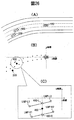
- the surrounding environment recognition system of this invention it is explanatory drawing regarding determination of the travel lane which a periphery moving body drive
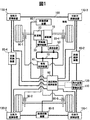
- FIG. 1 shows a surrounding environment for recognizing a surrounding moving body and road environment of the present invention in a vehicle system that recognizes the surrounding environment of the own vehicle 100 and supports driving of the own vehicle or controls driving of the own vehicle. It is one Example of the vehicle carrying the recognition apparatus 60, and has shown the outline
- FIG. 1 is a diagram in which a vehicle 100 equipped with a surrounding environment recognition device 60 has an upper side as a front side and a lower side as a rear side.
- a prime mover 10 for driving the vehicle 100 and a transmission for transmitting power of the prime mover 10 are illustrated.
- the vehicle 100 is driven by a prime mover control device 30 that controls the machine 20 and the prime mover 10.
- the prime mover 10 and the transmission 20 are mounted on the front side and the front side tire is driven. However, even when the rear side tire is driven or all four wheels are driven. The same applies hereinafter.
- the vehicle 100 includes a vehicle control device 40 that controls the entire vehicle, a communication device 50 that communicates with the outside, and four-wheel tires of the vehicle 100.
- a plurality of control devices such as installed braking devices (90-1, 90-2, 90-3, 90-4) are mounted, and these are connected to the control network 70 and communicate information with each other. ing.
- the surrounding environment recognition device 60 is mounted on the vehicle 100, and the image recognition devices (80-1, 80-2, 80-3, 80-) that acquire external environment information around the vehicle 100 are used.
- Speed, yaw rate, yaw angle, longitudinal acceleration, lateral acceleration, steering angle, etc. are received, the external information around the host vehicle 100 is recognized, and the vehicle control device 40 controls the entire vehicle according to the information.
- the vehicle state quantity indicating the state of the vehicle 100 is detected by a yaw rate sensor, an acceleration sensor, a speed sensor, a steering angle sensor, or the like not shown in FIG.
- the communication device 50 is a device that exchanges communications from the outside. For example, road surface information (road marker type and position such as lane marker position, stop line position, pedestrian crossing, etc.) and solid objects as road information in the vicinity of traveling Information (three-dimensional objects existing around the road such as signs, traffic lights, features, etc.) is acquired.
- This information includes information detected by sensors installed in road infrastructures, road peripheral information stored in the data center (road surface information and three-dimensional object information, etc.), road peripheral information detected by other vehicles (road surface information and three-dimensional information). It is also possible to acquire physical information etc. using the communication device 50.
- the image recognition device 80 (80-1, 80-2, 80-3, 80-4) is a device that acquires information to the outside world around the vehicle 100, and a specific example is image recognition by a camera.
- the camera include a monocular camera that recognizes the outside world with one camera and a stereo camera that recognizes the outside world with two cameras.
- the image recognition by the camera as the external information of the vehicle 100, a plurality of moving bodies moving around the vehicle 100 such as a vehicle, a pedestrian, a light vehicle (bicycle, etc.) can be simultaneously recognized, and further, the characteristics of the moving body are classified. Is possible.
- a stereo camera it is possible to detect the relative distances of moving objects and obstacles existing around the vehicle 100.
- the image recognition by the camera it is possible to acquire information such as the position and size of the lane marker (white line), the position of the stop line, and the position of the pedestrian crossing as road surface information painted on the road. Furthermore, as a three-dimensional object, it is possible to acquire the type, size, and position information of a sign that exists on the side of the road, the size and position information of a traffic light, and other specific three-dimensional feature position information. .
- the right rear recognition device 130-1, the left rear recognition device 130-2, the right front recognition device 130-3, and the left front recognition device 130-4 exist at the right rear, left rear, right front, and left front of the vehicle 100, respectively.
- Detect three-dimensional objects and obstacles In particular, by detecting the relative position and relative speed of a three-dimensional object such as a moving body or an obstacle in a region that cannot be detected only by the image recognition device 80, a three-dimensional object around the entire vehicle 100 is detected.
- the alarm device 110 and the display device 120 notify the driver by displaying the surrounding environment information of the host vehicle 100 recognized by the surrounding environment recognition device 60.
- notification / warning / display of the determination contents determined by the surrounding environment recognition device 60 based on the information on the surrounding vehicle and the traveling lane of the host vehicle is performed.
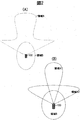
- FIG. 2 (A) and 2 (B) are examples showing an external environment recognition area by the image recognition device 80 mounted on the host vehicle 100.
- FIG. 2A and 2B as in the embodiment of FIG. 1, as the image recognition device 80, the image recognition device 80-1, the image recognition device 80-1 that recognizes the outside world ahead of the vehicle 100, and the vehicle 100 Recognition apparatus 80-2 for recognizing the outside world on the right side of the vehicle, an image recognition apparatus 80-3 for recognizing the outside world on the left side of the host vehicle 100, and an image recognition apparatus 80- for recognizing the outside world behind the host vehicle 100.
- 4 is a case where a camera is used.
- FIG. 1 As the image recognition device 80, the image recognition device 80-1, the image recognition device 80-1 that recognizes the outside world ahead of the vehicle 100, and the vehicle 100 Recognition apparatus 80-2 for recognizing the outside world on the right side of the vehicle, an image recognition apparatus 80-3 for recognizing the outside world on the left side of the host vehicle 100, and an image recognition apparatus 80- for recognizing the outside world behind the
- the image recognition device 80-1 that performs front external recognition is capable of recognizing both the external information in the vicinity of the wide angle and the external information in the distance with one image recognition device. It is possible to detect road surface information and solid object information existing in the range of A. That is, it is possible to detect road surface information such as a lane marker (white line) of a plurality of lanes on the road ahead of the host vehicle 100.
- the image recognition device 80-1 is a case where two image recognition devices are used, and a case where the region A2 which is a wide-angle region in the vicinity and the region A1 which is far are detected individually. is there.
- road surface information such as lane markers (white lines) of a plurality of lanes on the road existing ahead of the host vehicle 100 can be detected, as in FIG. Further, in FIGS. 2A and 2B, it is possible to detect not only the front side of the host vehicle 100 but also the outside world information on the right side and the rear side, and road lane markers (white lines) existing in the region B. It is possible to detect such information.
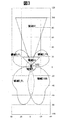
- FIG. 3 shows an image recognition device (80-1, 80-2, 80-3, 80-4) and a right rear recognition device 130-1, a left rear recognition device 130-2, a right front mounted on the host vehicle 100. Another embodiment of the outside recognition area by the recognition device 130-3 and the left front recognition device 130-4 is shown.
- the image recognition device 80 using the camera is used for the areas A1, A2, and B described in the embodiment of FIG. 2, and a radar sensor different from the camera is recognized around the host vehicle 100 in the right rear direction.
- the device 130-1, the left rear recognition device 130-2, the right front recognition device 130-3, and the left front recognition device 130-4 are mounted around the vehicle, and the right rear recognition device 130-1 and the left rear recognition device 130-2.
- the right front recognition device 130-3 and the left front recognition device 130-4 detect three-dimensional objects such as moving objects and obstacles around the host vehicle 100.
- the radar used as the right rear recognition device 130-1, the left rear recognition device 130-2, the right front recognition device 130-3, and the left front recognition device 130-4 is difficult to identify a moving object or an obstacle. However, when the distance and speed of the moving body and the obstacle are compared with those of the camera, it can be detected with relatively high accuracy. In the embodiment of FIG.
- the right rear recognition device 130-1, the left rear recognition device 130-2, the right front recognition device 130-3, and the left front recognition device 130-4 mounted on the host vehicle 100 have a region D_RR, The distance and speed of the moving body / obstacle in the region D_RL, the region D_FR, and the region D_FL are detected.
- road surface information around the vehicle 100 and solid objects are identified by a camera, and the distance between the solid objects is detected by radar, so that a more accurate three-dimensional object can be detected.
- FIG. 4 is a diagram showing a traveling scene in which the host vehicle 100 is traveling on a three-lane road on one side to the upper side in FIG.
- the host vehicle 100 is traveling in the center lane L2 of the three lanes, three vehicles are traveling in front of the host vehicle 100, the vehicle 301 is the lane L1, which is the left lane of the host vehicle, the vehicle 401 is traveling in the same lane L2 as the host vehicle, and the vehicle 201 is traveling in the lane L3 that is the right lane of the host vehicle.
- Three vehicles are running behind the host vehicle 100.
- the vehicle 202 is the lane L3 that is the right lane of the host vehicle, the vehicle 302 is L1 that is the left lane of the host vehicle, and the vehicle 402 is the host vehicle.
- the left lane marker of the lane L1 is LM1, the right lane marker is LM2, the left lane marker of the lane L2 is LM2, the right lane marker is LM3, the left lane marker of the lane L3 is LM3, and the right lane marker is LM4.
- the host vehicle 100 changes the lane L2 from traveling to the right lane L3, the relative distance between the front vehicle 201 and the rear vehicle 202 of the host vehicle 100 traveling on the right lane L3, the relative speed, Based on the speed of the host vehicle, it is determined that the vehicle 201 or the vehicle 202 does not collide, and an actual lane change operation is performed.
- the lane change is performed by paying attention to the vehicle traveling in the lane to be changed. For this reason, when determining whether a lane change is possible or if a lane change causes a collision with a surrounding vehicle, not only the relative position and relative speed of the peripheral mobile object, but also the peripheral mobile object travels. It is necessary to determine which lane the lane is on.
- an image recognition device 80-1 capable of detecting a moving body is installed.
- the image recognition device 80-1 it is more preferable to use a stereo camera that detects the relative position of a three-dimensional object or road surface paint from parallax using two cameras. By applying such a stereo camera to the image recognition device 80-1, it is possible to detect a moving object and a lane marker far in front of the vehicle. Therefore, in the case of FIG. 4, the vehicles 201, 401, and 301 that are moving bodies ahead can be detected by the image recognition device 80-1, the right front recognition device 130-1, and the left front recognition device 130-4.
- the positions of the lane marker LM2 and the lane marker LM3 can be detected by the image recognition device 80-1. Therefore, the relative positions of the vehicles 201, 401, 301 with respect to the host vehicle 100 detected by the image recognition device 80-1, the right front recognition device 130-3, and the left front recognition device 130-4 and the two image recognition devices 80-1 are detected. It is possible to determine which lane the vehicle 201, 401, 301 is traveling in the lanes L1, L2, L3 from the relationship of the relative positions of the lane marker LM2 and the lane marker LM3 with respect to the host vehicle 100. On the other hand, as described in FIG.
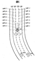
- FIG. 5 is a diagram showing another traveling scene in which the host vehicle 100 is traveling on a three-lane road on one side to the upper side in FIG.
- the host vehicle 100 travels in the center lane L2 of three lanes, two vehicles are traveling behind the host vehicle 100, and the vehicle 200 is in the lane L3, which is the right lane of the host vehicle.
- the vehicle 300 is traveling in the left lane L1 of the host vehicle.
- the left lane marker of the lane L1 is LM1
- the right lane marker is LM2
- the left lane marker of the lane L2 is LM2
- the right lane marker is LM3
- the right lane marker is LM4.
- the image recognition device 80-1 installed in order to accurately grasp the situation ahead of the host vehicle 100 traveling detects the left lane marker LM2 and the right lane marker LM3 in front of the lane L2 on which the host vehicle 100 is traveling.
- the positions of the upper points LMP3-1, LMP3-2, LMP3-3, LMP3-4, LMP3-5, LMP3-6, and LMP3-7 are output in the host vehicle coordinate system.
- the position coordinate point sequence data of LMP 3-1, LMP 3-2, LMP 3-3, LMP 3-4, LMP 3-5, LMP 3-6, and LMP 3-7 is the forward lane marker point sequence data of the lane L 2 on which the host vehicle 100 is traveling. Become.
- FIG. 6 shows an embodiment of a specific configuration of the surrounding environment recognition device 40 shown in FIG.
- the surrounding environment recognition device 40 information on the surrounding environment of the host vehicle 100 detected by the image recognition devices 80-1 to 80-4, the right rear recognition device 130-1, the left rear recognition device 130-2, the right front recognition device 130. ⁇ 3, based on the information on the moving body around the host vehicle 100 detected by the left front recognition device 130-4, the status of the surrounding environment of the host vehicle 100 is output.
- the surrounding environment recognition device 40 includes a first lane marker estimation unit 610, a second lane marker detection unit 620, a surrounding moving body detection unit 630, a lane marker estimated value correction unit 640, and a surrounding moving body determination unit 650.
- Display means 660 and notification means 670 are examples of the surrounding environment recognition device 40.
- the first lane marker estimation means 610 includes lane marker position point sequence data in front of the host vehicle 100 acquired by the image recognition devices 80-1 to 80-4, lane marker position point sequence data on the side of the host vehicle 100, Using the position point sequence data of the lane marker in the vicinity of the rear of the host vehicle 100 or the position point sequence data of the lane marker in the vicinity of the host vehicle 100 obtained by other means, the position point sequence data of the rear lane marker of the host vehicle 100 is obtained.
- the second lane marker detection means 620 is the position point sequence data of the lane marker in the vicinity of the detected vehicle 100 acquired by the image recognition devices 80-1 to 80-4 (the vicinity of the front, the side and the vicinity of the vehicle 100).
- Lane marker position point sequence data is output as lane marker position point sequence data in the vicinity of the host vehicle 100.
- the lane marker estimated value correcting unit 640 is based on the position point sequence data of the lane marker in the vicinity of the host vehicle 100 output from the second lane marker detecting unit 620, and the lane marker estimated value correcting unit 640 of the host vehicle 100 is output.
- the estimated value of the position point sequence data of the rear lane marker is corrected, and the corrected position point sequence data of the rear lane marker is output.
- the peripheral moving body detection means 630 includes image recognition devices 80-1 to 80-4, a right rear recognition device 130-1, a left rear recognition device 130-2, a right front recognition device 130-3, and a left front recognition device 130-.
- the peripheral moving body determination means 650 includes the corrected position point sequence data of the rear lane marker output from the lane marker estimated value correction means 640 and the moving object / vehicle existing around the host vehicle 100 output from the peripheral moving body detection means 630. From the relative position data of the obstacle, the relative position data of the moving object / obstacle existing in the vicinity of the host vehicle 100 and the information on the lane in which the vehicle travels are output. The display unit 660 and the notification unit 670 output information to be output to the display device 120 and the alarm device 110 based on the determination result of the peripheral moving body determination unit 650.
- FIG. 7 shows an example of a specific configuration of the first lane marker estimating means 610.
- the first lane marker estimation unit 610 includes a vehicle behavior estimation unit 611, a lane marker storage unit 612, and a rear lane marker estimation unit 613.
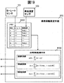
- the vehicle behavior estimation means 611 includes a yaw rate sensor 101 that detects the yaw rate of the host vehicle 100 mounted on the host vehicle 100, a steering angle sensor 102 that detects the steering angle of the host vehicle 100, and a vehicle that detects the speed of the host vehicle 100. Each sensor detection signal output from the speed sensor 103 is acquired and stored.
- the travel locus of the host vehicle 100 is calculated using the stored yaw rate, steering angle, and vehicle speed data, so that the position where the host vehicle 100 has moved and the angle at which the vehicle 100 turns are output.
- the lane marker storage unit 612 stores the front, side, and rear lane markers of the host vehicle 100 acquired from the lane marker detection unit 800 that outputs the front, side, and rear lane markers of the host vehicle 100.
- the lane marker detection means 800 is a lane marker position point sequence data in front of the host vehicle 100 acquired by the image recognition devices 80-1 to 80-4, a lane marker position point sequence data on the side of the host vehicle 100, The position point sequence data of the lane marker near the back of the host vehicle 100 or the position point sequence data of the lane marker around the host vehicle 100 obtained by other means is output.
- the rear lane marker estimation means 613 is a distance traveled by the own vehicle 100 output from the vehicle behavior estimation means 611, an angle at which the vehicle 100 turns, and past lane marker positions around the own vehicle 100 stored in the lane marker storage means 612. The point sequence data is acquired, and the position point sequence data of the current rear lane marker of the host vehicle 100 is estimated and output.
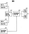
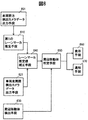
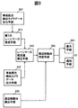
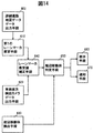
- FIG. 8 to 14 show another embodiment of the specific configuration of the surrounding environment recognition device 40 shown in FIG. Specifically, an embodiment is shown in which the combination of the target for acquiring the position point sequence data of the lane marker around the host vehicle 100 used for the first lane marker estimation means 610 and the second lane marker detection means 620 is different.
- the position point sequence data of the forward lane marker of the host vehicle 100 output by the vehicle forward detection camera data output means 801 is used to generate the second lane marker estimation means 610 shown in FIG.
- the lane marker detection unit 620 uses the position point sequence data of the lane markers before and after the vehicle 100 output from the vehicle all-around detection camera data output unit 621.
- the vehicle front detection camera data output means 801 shown in FIG. 8 outputs the position point sequence data of the lane marker in front of the host vehicle 100 detected by the image recognition device 80-1 shown in FIG.
- the image recognition device 80-1 it is preferable to use a stereo camera that can detect the position of a distant lane marker using two cameras as described above.
- a monocular camera that detects the position of a distant lane marker with one camera may be used.
- the detection of the forward lane marker of the host vehicle 100 may be performed by detecting only the position point sequence data of the left and right lane markers of the traveling lane in which the host vehicle 100 travels, but the position point sequence data of the lane markers of the left and right lanes of the traveling lane. May also be detected together.
- the image recognition device 80-1 has a periphery (front and rear, around the subject vehicle 100 detected by the image recognition devices 80-1, 80-2, 80-3, 80-4 shown in FIG. This is when the position point sequence data of the lane marker on the left-hand side is output.
- the image recognition device 80-1 a stereo camera using two cameras may be used as described above, or a monocular camera that detects the position of the lane marker may be used.
- the image recognition devices 80-2, 80-3, and 80-4 preferably use a relatively inexpensive monocular camera.
- the detection of the lane markers in the vicinity of the host vehicle 100 may detect only the position point sequence data of the left and right lane markers of the traveling lane in which the host vehicle 100 travels, but the position marker sequence of the lane markers in the left and right lanes of the traveling lane Data may be detected together.
- the first lane marker estimating means 610 estimates the position point sequence data of the rear lane marker of the host vehicle 100 using the position point sequence data of the lane marker ahead of the host vehicle 100, and corrects the lane marker estimated value correction.
- the means 640 corrects the estimated value of the position point sequence data of the rear lane marker of the host vehicle 100 using the position point sequence data of the lane marker in the vicinity (front and rear, left and right sides) of the host vehicle 100.
- the vehicle front detection camera data output means 801 detects the own vehicle detected by the image recognition device 80-1 which is a stereo camera capable of detecting up to the position of a distant lane marker using two cameras.
- the image recognition device 80-1 which is a stereo camera capable of detecting up to the position of a distant lane marker using two cameras.
- the position point sequence data of the forward lane marker of the host vehicle 100 output by the vehicle forward detection camera data output means 801 is used to generate the second lane marker estimation means 610 shown in FIG.
- the lane marker detection unit 620 uses the position point sequence data of the left and right lane markers of the host vehicle 100 output from the vehicle side detection camera data output unit 622.
- the vehicle forward detection camera data output means 801 shown in FIG. 9 outputs the position point sequence data of the lane marker in front of the host vehicle 100 detected by the image recognition device 80-1 shown in FIG.
- the image recognition device 80-1 it is preferable to use a stereo camera that can detect the position of a distant lane marker using two cameras as described above.
- a monocular camera that detects the position of a distant lane marker with one camera may be used.
- the detection of the forward lane marker of the host vehicle 100 may be performed by detecting only the position point sequence data of the left and right lane markers of the traveling lane in which the host vehicle 100 travels, but the position point sequence data of the lane markers of the left and right lanes of the traveling lane. May also be detected together.
- the image recognition devices 80-2 and 80-4 preferably use a relatively inexpensive monocular camera.
- the detection of the lane markers in the vicinity of the host vehicle 100 may detect only the position point sequence data of the left and right lane markers of the traveling lane in which the host vehicle 100 travels, but the position marker sequence of the lane markers in the left and right lanes of the traveling lane Data may be detected together.
- FIG. 1 In the embodiment of FIG. 1
- the first lane marker estimation means 610 estimates the position point sequence data of the rear lane marker of the host vehicle 100 using the position point sequence data of the lane marker ahead of the host vehicle 100, and corrects the lane marker estimated value.
- the means 640 corrects the estimated value of the position point sequence data of the rear lane marker of the host vehicle 100 using the position point sequence data of the left and right lane markers of the host vehicle 100.
- the vehicle front detection camera data output means 801 detects the own vehicle detected by the image recognition device 80-1 which is a stereo camera capable of detecting up to the position of a distant lane marker using two cameras.
- the detailed data of the road on which the host vehicle 100 is traveling are stored as input data to the first lane marker estimating means 610 shown in FIG. 6, and the host vehicle 100 acquired from the stored detailed data.
- the second lane marker detection means 620 shown in FIG. 6 the position of the front and rear lane markers in the vicinity of the host vehicle 100 output by the vehicle all-around detection camera data output means 621 is used. It is an Example at the time of using point sequence data.
- the detailed road map data output means 802 shown in FIG. 10 stores the road shape data and lane marker shape data around the vehicle 100 traveled by the communication device 50 shown in FIG. 1 in a storage device (not shown). In other words, the stored lane marker shape data is output.
- the lane marker shape data may acquire only the position point sequence data of the left and right lane markers of the traveling lane of the host vehicle 100, but also acquires the position point sequence data of the lane markers of the left and right lanes of the traveling lane. You may do it.
- the vehicle all-around detection camera data output means 621 shown in FIG. 10 has a periphery (front and rear, around the subject vehicle 100 detected by the image recognition devices 80-1, 80-2, 80-3, 80-4 shown in FIG. This is when the position point sequence data of the lane marker on the left (right side) is output.
- the image recognition device 80-1 a stereo camera using two cameras may be used as described above, or a monocular camera that detects the position of the lane marker may be used.
- the image recognition devices 80-2, 80-3, and 80-4 preferably use a relatively inexpensive monocular camera.
- the detection of the lane markers in the vicinity of the host vehicle 100 may detect only the position point sequence data of the left and right lane markers of the traveling lane in which the host vehicle 100 travels, but the position marker sequence of the lane markers in the left and right lanes of the traveling lane Data may be detected together.
- the first lane marker estimating means 610 uses the position point sequence data of the lane marker around the own vehicle acquired from the road map data around the own vehicle 100 to obtain the position point of the rear lane marker of the own vehicle 100.
- the column data is estimated, and the lane marker estimated value correcting means 640 estimates the position point sequence data of the rear lane marker of the host vehicle 100 using the position point sequence data of the lane marker around the host vehicle 100 (front and rear, left and right side). Correct the value.
- the detailed road map data output means 802 stores the road shape data and lane marker shape data around the vehicle 100 traveling in a storage device (not shown), and stores the stored lane marker shape. By outputting the data, it is possible to detect the accurate shape of the forward lane marker of the host vehicle 100 over a wide range. Therefore, the shape of the lane marker behind the host vehicle 100 estimated by the first lane marker estimating means 610 is an accurate shape. Can be output.
- the detailed data of the road on which the own vehicle 100 is traveling is stored, and the own vehicle 100 acquired from the stored detailed data.
- the second lane marker detection means 620 shown in FIG. 6 the position point sequence data of the side lane marker of the host vehicle 100 output from the vehicle side detection camera data output means 622 is used as the second lane marker detection means 620 shown in FIG. It is an Example when used.
- the detailed road map data output means 802 shown in FIG. 11 stores the road shape data and lane marker shape data around the vehicle 100 traveled by the communication device 50 shown in FIG. 1 in a storage device (not shown). In other words, the stored lane marker shape data is output.
- the lane marker shape data may acquire only the position point sequence data of the left and right lane markers of the traveling lane of the host vehicle 100, but also acquires the position point sequence data of the lane markers of the left and right lanes of the traveling lane. You may do it.
- the vehicle side detection camera data output means 622 shown in FIG. 11 outputs position point sequence data of lane markers on the left and right sides of the own vehicle 100 detected by the image recognition devices 80-2 and 80-4 shown in FIG. It will be the case.
- the image recognition devices 80-2 and 80-4 preferably use a relatively inexpensive monocular camera.
- the detection of the lane markers in the vicinity of the host vehicle 100 may detect only the position point sequence data of the left and right lane markers of the traveling lane in which the host vehicle 100 travels, but the position marker sequence of the lane markers in the left and right lanes of the traveling lane Data may be detected together.
- the first lane marker estimating means 610 uses the position point sequence data of the lane marker around the own vehicle acquired from the road map data around the own vehicle 100 to obtain the position point of the rear lane marker of the own vehicle 100.
- the column data is estimated, and the lane marker estimated value correction unit 640 corrects the estimated value of the position point sequence data of the rear lane marker of the host vehicle 100 using the position point sequence data of the left and right lane markers of the host vehicle 100.
- the detailed road map data output means 802 stores the road shape data and lane marker shape data around the vehicle 100 traveling in a storage device (not shown), and stores the stored lane marker shape. By outputting the data, it is possible to detect the accurate shape of the forward lane marker of the host vehicle 100 over a wide range. Therefore, the shape of the lane marker behind the host vehicle 100 estimated by the first lane marker estimating means 610 is an accurate shape. Can be output.
- the lane marker detection unit 620 uses the position point sequence data of the lane marker in the vicinity of the host vehicle 100 output from the vehicle rear detection camera data output unit 623.
- the vehicle front detection camera data output means 801 shown in FIG. 12 outputs the position point sequence data of the lane marker in front of the host vehicle 100 detected by the image recognition device 80-1 shown in FIG.
- the image recognition device 80-1 it is preferable to use a stereo camera that can detect the position of a distant lane marker using two cameras as described above.
- a monocular camera that detects the position of a distant lane marker with one camera may be used.
- the detection of the forward lane marker of the host vehicle 100 may be performed by detecting only the position point sequence data of the left and right lane markers of the traveling lane in which the host vehicle 100 travels, but the position point sequence data of the lane markers of the left and right lanes of the traveling lane. May also be detected together.
- the vehicle rear detection camera data output means 623 shown in FIG. 12 outputs the position point sequence data of the lane marker behind the host vehicle 100 detected by the image recognition device 80-3 shown in FIG.
- a stereo camera using two cameras may be used as the image recognition device 80-3, or a monocular camera that detects the position of the lane marker may be used.
- a monocular camera that detects the position of the lane marker may be used.
- the detection of the lane markers in the vicinity of the host vehicle 100 may detect only the position point sequence data of the left and right lane markers of the traveling lane in which the host vehicle 100 travels, but the position marker sequence of the lane markers in the left and right lanes of the traveling lane Data may be detected together.
- the first lane marker estimating means 610 estimates the position point sequence data of the rear lane marker of the host vehicle 100 using the position point sequence data of the lane marker ahead of the host vehicle 100, and corrects the lane marker estimated value correction.
- the means 640 corrects the estimated value of the position point sequence data of the rear lane marker of the host vehicle 100 using the position point sequence data of the rear lane marker of the host vehicle 100.
- the vehicle front detection camera data output means 801 detects the own vehicle detected by the image recognition device 80-1 which is a stereo camera capable of detecting up to the position of a distant lane marker using two cameras.
- the position point sequence data of the side lane marker of the own vehicle 100 output from the vehicle side detection camera data output means 803 is used.
- the position point sequence data of the lane marker in the vicinity of the host vehicle 100 output from the vehicle rear detection camera data output means 623 is used as the second lane marker detection means 620.
- the vehicle side detection camera data output means 803 shown in FIG. 13 outputs the position point sequence data of the left and right lane markers of the host vehicle 100 detected by the image recognition devices 80-2 and 80-4 shown in FIG. It becomes.
- the image recognition devices 80-2 and 80-4 either a stereo camera or a monocular camera may be used, but it is preferable to use a relatively inexpensive monocular camera.
- the detection of the side lane marker of the host vehicle 100 may detect only the position point sequence data of the left and right lane markers of the traveling lane in which the host vehicle 100 travels, but the position point sequence of the lane marker of the left and right lanes of the traveling lane Data may be detected together.
- the vehicle rear detection camera data output means 623 shown in FIG. 13 outputs the position point sequence data of the lane marker behind the host vehicle 100 detected by the image recognition device 80-3 shown in FIG.
- a stereo camera using two cameras may be used as the image recognition device 80-3, or a monocular camera that detects the position of the lane marker may be used.
- a monocular camera that detects the position of the lane marker may be used.
- the detection of the rear lane marker in the vicinity of the host vehicle 100 may detect only the position point sequence data of the left and right lane markers of the travel lane in which the host vehicle 100 travels, but the position of the lane marker in the left and right lanes of the travel lane Point sequence data may also be detected together.
- the first lane marker estimating means 610 estimates the position point sequence data of the rear lane marker of the host vehicle 100 using the position point sequence data of the lane marker on the side of the host vehicle 100, and the lane marker estimated value
- the correction unit 640 corrects the estimated value of the position point sequence data of the rear lane marker of the host vehicle 100 using the position point sequence data of the rear lane marker of the host vehicle 100.
- the vehicle front detection camera data output means 801 detects the own vehicle detected by the image recognition device 80-1 which is a stereo camera capable of detecting up to the position of a distant lane marker using two cameras.
- the detailed data of the road on which the own vehicle 100 is traveling is stored, and the own vehicle 100 acquired from the stored detailed data.
- the second lane marker detection unit 620 shown in FIG. 6 the position point sequence data of the lane marker in the vicinity of the host vehicle 100 output from the vehicle rear detection camera data output unit 623 is used.
- the detailed road map data output means 802 shown in FIG. 14 stores the road shape data and lane marker shape data around the vehicle 100 traveled by the communication device 50 shown in FIG. 1 in a storage device (not shown). In other words, the stored lane marker shape data is output.
- the lane marker shape data may acquire only the position point sequence data of the left and right lane markers of the traveling lane of the host vehicle 100, but also acquires the position point sequence data of the lane markers of the left and right lanes of the traveling lane. You may do it.
- the vehicle rear detection camera data output means 623 shown in FIG. 14 outputs the position point sequence data of the lane marker behind the host vehicle 100 detected by the image recognition device 80-3 shown in FIG.
- a stereo camera using two cameras may be used as the image recognition device 80-3, or a monocular camera that detects the position of the lane marker may be used. However, it is preferable to use a relatively inexpensive monocular camera.
- the detection of the rear lane marker in the vicinity of the host vehicle 100 may detect only the position point sequence data of the left and right lane markers of the travel lane in which the host vehicle 100 travels, but the position of the lane marker in the left and right lanes of the travel lane Point sequence data may also be detected together.
- the first lane marker estimating means 610 uses the position point sequence data of the lane marker around the own vehicle acquired from the road map data around the own vehicle 100 to set the position point of the rear lane marker of the own vehicle 100.
- the column data is estimated, and the lane marker estimated value correction unit 640 corrects the estimated value of the position point sequence data of the rear lane marker of the host vehicle 100 using the position point sequence data of the rear lane marker of the host vehicle 100.
- the vehicle front detection camera data output means 801 detects the own vehicle detected by the image recognition device 80-1 which is a stereo camera capable of detecting up to the position of a distant lane marker using two cameras.
- the image recognition device 80-1 which is a stereo camera capable of detecting up to the position of a distant lane marker using two cameras.
- a plurality of embodiments of the second lane marker detection means 620 for outputting the lane marker are described. However, any means is combined to output the data of the position and shape of the lane marker to the first lane marker estimation means 610. May be output to the lane marker estimated value correcting means 640 to output detection data of the positions of lane markers in the vicinity of the host vehicle 100.
- the first lane marker estimation means 610 receives the lane marker position and shape data. There is an effect that it is possible to estimate the rear lane marker even when any of the means for outputting and the means for outputting the detection data of the position of the lane marker around the host vehicle 100 to the lane marker estimated value correcting means 640 becomes abnormal. is there.
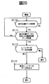
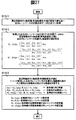
- FIG. 15 estimates the position point sequence data of the lane marker behind the host vehicle 100 in the present invention, determines the lane in which the peripheral mobile body travels from the position data of the peripheral mobile body, and displays the state of the peripheral mobile body.
- An example of the whole flowchart to notify is shown.
- the surrounding environment recognition system estimates the position point sequence data of the lane marker behind the host vehicle 100 (S1).
- the data described with respect to the first lane marker estimation means 610 shown in FIGS. 8 to 14 is used.
- it is determined whether the position point sequence data of the lane marker behind S1 has been estimated S2).
- the process proceeds to S9. If it is determined that estimation is possible, the process proceeds to S3. In S3, the position point sequence data of the lane marker in the vicinity of the periphery of the host vehicle 100 is acquired (S3). As the lane marker position point sequence data in the vicinity of the periphery of the host vehicle 100, the data described with respect to the second lane marker detection means 620 shown in FIGS.
- the lane in which the moving body around the own vehicle 100 is traveling is determined from the position data of the moving body around the own vehicle 100 detected by the right front recognition device 130-3 and the left front recognition device 130-4.
- the position data of the peripheral mobile body and the position point sequence data of the lane marker behind the host vehicle 100 output in S6 are displayed on the monitor.
- the position point sequence data of the rear lane marker cannot be estimated, the position point sequence data of the lane marker in the vicinity of the host vehicle 100 is acquired in S9.
- the lane marker position point sequence data in the vicinity of the periphery of the host vehicle 100 As the lane marker position point sequence data in the vicinity of the periphery of the host vehicle 100, the data described with respect to the second lane marker detection means 620 shown in FIGS. Next, in S9, a lane marker near the periphery of the host vehicle 100 is detected, and in S10, it is determined whether or not position point sequence data of the lane marker near the periphery has been acquired.
- the position point sequence data of the lane marker in the vicinity of the periphery of the host vehicle 100 cannot be acquired, the position point sequence data of the lane marker cannot be output (S11), and the image recognition devices 80-1 to 80-4 and the right rear recognition are performed.
- the position data of the moving body and the position point sequence data of the lane markers near the periphery of the host vehicle 100 are displayed on the monitor (S15). If the position point sequence data of the lane marker near the periphery of the host vehicle 100 cannot be acquired in S4, the position point sequence data of the rear lane marker estimated in S1 cannot be corrected (S13), and the image recognition device 80-1 Position data of moving bodies around the host vehicle 100 detected by 80-4 and the right rear recognition device 130-1, the left rear recognition device 130-2, the right front recognition device 130-3, and the left front recognition device 130-4. Then, the position point sequence data of the rear lane marker not corrected and estimated in S1 is displayed on the monitor (S16).
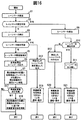
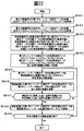
- FIG. 16 estimates the position point sequence data of the lane marker behind the host vehicle 100 in the present invention, determines the lane in which the peripheral mobile body travels from the position data of the peripheral mobile body, and changes the lane of the host vehicle 100.
- the example of the whole flowchart at the time of applying to a vehicle is shown.
- the processing from S1 to S13 in the flowchart of FIG. 16 is the same as that from S1 to S13 in the flowchart of FIG.
- the difference between FIG. 15 and FIG. 16 is the part of the processing related to the control of the vehicle line change from S17 to S21.
- the position point sequence data of the lane marker behind the own vehicle 100 output in S6, the image recognition devices 80-1 to 80-4 and the right rear recognition device 130-1, the left
- the moving body around the host vehicle 100 is traveling from the position data of the moving body around the own vehicle 100 detected by the rear recognition device 130-2, the right front recognition device 130-3, and the left front recognition device 130-4.
- the position data and the travel lane information of the peripheral mobile body and the position point sequence data of the lane marker behind the host vehicle 100 output in S6. Is output.
- S17 it is determined whether or not there is a lane change request in the host vehicle 100.
- the process proceeds to S18, and the relative position, relative speed, etc. of the surrounding moving body of the host vehicle 100 determined that the host vehicle 100 is present in the lane to be changed lanes.
- the possibility of collision when the host vehicle 100 changes lanes is estimated from the information, and it is determined whether or not lane changes are possible.
- the possibility of collision associated with the lane change is not estimated, and the process returns. Similarly to the case of FIG.
- the position point sequence data of the lane marker cannot be output (S11), and it cannot be determined whether the lane can be changed. Is notified to the vehicle control device 40, the display device 120, and the alarm device 110 (S21).
- the position point sequence data of the lane marker can be detected at S10, only the position point sequence data of the lane marker near the periphery of the host vehicle 100 detected at S12 is output, and it is determined that it is not possible to determine whether or not the lane can be changed.
- the device 40, the display device 120, and the alarm device 110 are notified (S20).
- the position point sequence data of the rear lane marker estimated in S1 cannot be corrected. Therefore, the position point sequence data of the uncorrected rear lane marker estimated in S1 is output in S13. As described above, the position point sequence data of the uncorrected rear lane marker estimated in S1 is output to the vehicle control device 40, and the vehicle control device 40, the display device 120, and the alarm device 110 are notified that it is not possible to determine whether the lane can be changed. (S19).
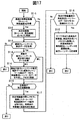
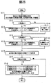
- FIG. 17 shows a detailed flowchart regarding the lane marker estimation (S1) of FIGS.
- the yaw rate and vehicle speed of the host vehicle indicating the vehicle behavior of the host vehicle 100 are acquired (S1-1).
- the yaw rate and vehicle speed of the host vehicle 100 indicating the vehicle behavior are output at a predetermined cycle, and when the yaw rate and vehicle speed can be acquired, the acquired time, yaw rate, and vehicle speed values are stored in the memory (S1). -2), go to S1-3. If the yaw rate and the vehicle speed are not obtained by acquisition, the process proceeds to S1-3.
- the position point sequence data of the lane markers in front of and around the host vehicle 100 input to the first lane marker estimation means 610 is acquired.
- the position point sequence data of the lane marker is output at a predetermined cycle different from the predetermined cycle in which the yaw rate or vehicle speed of the host vehicle 100 indicating the vehicle behavior is output.
- the position point sequence data of the forward lane marker of the host vehicle 100 detected by the image recognition device 80-1 and output by the vehicle forward detection camera data output means 801, or the image recognition devices 80-2, 80 -4, and the position point sequence data of the side lane marker of the own vehicle 100 output by the vehicle side detection camera data output means 803 is acquired.
- the process returns to the start. Further, if position point sequence data of a new lane marker can be acquired, the process proceeds to the next S1-4.
- S1-4 is executed for each cycle in which the position point sequence data of the lane marker is output. In S1-4, the presence / absence of the latest value of the corrected data of the position point sequence data estimated value of the rear lane marker obtained by correcting the estimated value of the position point sequence data of the rear lane marker performed in S5 of FIG. 16 is confirmed.
- the process proceeds to S1-5, and the position point sequence data estimated value of the rear lane marker is obtained. If there is no corrected data, the process proceeds to S1-6.
- S 1-5 the position of the latest lane marker position point sequence data detected in S 1-3 and the corrected data of the latest rear lane marker position point sequence data estimate value are combined to determine the position of the lane marker around the host vehicle 100. Point sequence data is created, creation time and data are stored in memory. Next, in S1-6, it is determined whether or not the host vehicle 100 has moved a predetermined distance.
- the distance to the farthest lane marker position from the own vehicle 100 is set in front of the own vehicle 100 in the latest detected position point sequence data of the lane marker acquired in S1-3. Etc. That is, when the host vehicle 100 moves to the position of the farthest lane marker in front of the host vehicle 100 detected, the position point sequence data of the detected front lane marker is moving to the rear of the host vehicle. The position point sequence data of these lane markers can be used as the position point sequence data of the current lane marker behind the host vehicle 100. If the host vehicle 100 has not moved the predetermined distance in S1-6, the process returns to the start because it cannot be used as the data of the rear lane marker of the host vehicle 100.
- the process proceeds to S1-7 because it can be used as the data of the rear lane marker of the host vehicle 100.
- S1-7 while the host vehicle 100 moves a predetermined distance, the array data of the vehicle state quantities (yaw rate and vehicle speed) stored in the memory in S1-2 is acquired, and the host vehicle 100 sets the predetermined distance. The movement amount of the own vehicle 100 and the turning angle of the own vehicle 100 when moving are calculated.
- S1-8 the position point sequence data of the lane markers around the host vehicle 100 before the host vehicle 100 moves a predetermined distance is acquired from the memory.
- the position point sequence data of the lane markers around the host vehicle 100 is created every predetermined time period and stored in the memory together with the created time.
- the host vehicle 100 moves a predetermined distance.
- Data can be acquired by selecting position point sequence data of lane markers around the host vehicle 100 at the previous time.
- the position point sequence data of the lane markers around the host vehicle 100 before the host vehicle 100 moves a predetermined distance may not be stored in the memory. In this case, the process returns to the start. .
- the process proceeds to S1-9.
- the host vehicle 100 sets the predetermined distance by using the accurate movement amount of the host vehicle 100 and the turning angle of the host vehicle 100 when the host vehicle 100 calculated in S1-7 moves the predetermined distance.
- the position point sequence data of the lane marker behind the current host vehicle 100 is calculated by moving the position point sequence data of the lane marker around the host vehicle 100 before moving in parallel and rotating.
- the position point sequence data of lane markers around the host vehicle 100 before the host vehicle 100 moves a predetermined distance using the movement amount of the host vehicle 100 and the turning angle of the host vehicle 100 in S1-9.
- An embodiment of a specific method for calculating the position point sequence data of the lane marker behind the host vehicle 100 by performing parallel movement and rotational movement will be described.
- the traveling direction of the host vehicle 100 at the position 100-1 of the host vehicle 100 before moving is a positive value of the x-axis coordinate
- the left side in the lateral direction of the host vehicle 100 perpendicular to the traveling direction of the host vehicle 100 is y.
- the axis coordinate is in the positive direction
- the amount of movement of the host vehicle 100 in the x-axis coordinate direction is ⁇ x
- the amount of movement of the host vehicle 100 in the y-axis coordinate direction is ⁇ y.
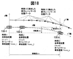
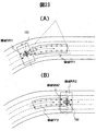
- FIG. 18 is an explanatory diagram relating to the calculation of the movement amount and turning angle of the host vehicle 100 described in S1-7 of FIG.
- the position of the own vehicle 100 at a certain time t1 is indicated by the own vehicle 100-1
- the position of the own vehicle 100 at the time t2 is indicated by the own vehicle 100-2
- the position of the own vehicle 100 at the time tn is indicated by the own vehicle 100-2.
- a vehicle 100-n is shown.
- the position at time t1 is a position before the host vehicle 100 moves
- the position at time tn is a position after the host vehicle 100 has moved. Since the host vehicle 100 travels along the road shape, it may be in a state of turning as well as straight traveling.
- the vehicle coordinate system of the host vehicle 100 at time t1 is represented, the traveling direction of the host vehicle 100 is represented as x-axis coordinates, and the left side in the lateral direction of the host vehicle is represented as positive in the y-axis coordinate system.
- Time t1 and time t2 indicate the position of the vehicle behavior output yaw rate and vehicle speed for each output cycle, the yaw rate at time t1 is ⁇ 1, the vehicle speed is Vown_1, the yaw rate at time t2 is ⁇ 2, and the vehicle speed is Vown_2, the yaw rate at time tn is ⁇ n, and the vehicle speed is Vown_n.
- the position data of the front lane marker represented by the white circle in FIG. 18 is detected
- time t2 the position data of the front lane marker represented by the black circle in FIG. 18 is detected. As shown in FIG.
- the position before the host vehicle 100 moves a predetermined distance is the host vehicle 100-1 at time t1
- the position after the host vehicle 100 moves a predetermined distance wp is the host vehicle 100 at time tn.
- ⁇ n the movement amount ⁇ x, the movement amount ⁇ y, and the turning angle ⁇ are as shown in FIG. A specific method of calculating the movement amounts ⁇ x and ⁇ y and the turning angle ⁇ will be described with reference to FIG.
- the position point sequence data of the left lane marker ahead of the host vehicle 100 acquired at time t1 is the point sequence data at the position indicated by the white circle in FIG.
- the data of these point sequences is expressed as follows.
- Rx_LLi is the distance in the i-th x-axis coordinate system from the position near the own vehicle 100 at the left lane marker of the own vehicle 100
- Ry_LLi is i-th from the position near the own vehicle 100 in the left lane marker of the own vehicle 100.
- the distance in the y-axis coordinate system is shown.
- the position point sequence data of the left lane marker ahead of the host vehicle 100 has m point sequence data. If the host vehicle 100 has moved to the position of the host vehicle 100-n at time tn, the point sequence data at the position indicated by the white circle in FIG. 18 acquired at time t1 is the host vehicle 100-n at time tn. This is the position point sequence data of the rear lane marker.
- the position point sequence data expressed by Equation 1 is the position point sequence data expressed by the x-axis coordinates and the y-axis coordinates that are the vehicle coordinate system of the host vehicle 100-1 at time t1
- the host vehicle 100-n It is necessary to convert to position point sequence data based on the vehicle coordinate system at the position of.
- the position point sequence data expressed by the x-axis coordinate and the y-axis coordinate which is the vehicle coordinate system of the host vehicle 100-1 at time t1
- the conversion to position point sequence data expressed in () can be expressed by the following expression.
- the position point sequence data expressed in the vehicle coordinate system (x′-axis coordinates and y′-axis coordinates) at the position of the host vehicle 100-n is expressed as follows.
- FIG. 19 is an explanatory diagram showing a specific configuration of the vehicle behavior estimation means 610 shown in FIG. 7, and shows the movement amount and turning angle of the host vehicle 100 described in S1-7 of the flowchart shown in FIG. Calculate.
- Data acquired from the yaw rate sensor 101 and the vehicle speed sensor 103 at a predetermined cycle is stored in the memory 6101 together with the acquired time.
- the yaw rate and vehicle speed data acquired at time t1 shown in FIG. 18 and the yaw rate and vehicle speed data acquired at time t2 are sequentially stored in the memory. Since the memory for storing data only needs to be stored for a predetermined time, a method such as storing the latest data while discarding old data, such as a ring buffer, can be used.
- the vehicle behavior estimating means 610 acquires the yaw rate and the vehicle speed while the vehicle 100 is moving from the memory 6101, and sets the movement amount and turning angle of the own vehicle 100 at 6102. Calculate. Specifically, as shown in FIG. 18, the own vehicle 100 moves from the own vehicle 100-1 at time t1 to the own vehicle 100-n at time tn, and the amount of movement is a predetermined moving distance. explain.
- the movement amount ⁇ x (movement amount in the x-axis direction in FIG. 18) and the movement amount ⁇ y (movement amount in the y-axis direction in FIG. 18) are as follows.
- FIG. 20 shows another detailed flowchart regarding the lane marker estimation (S1) of FIGS.
- S1 the first lane marker estimation means shown in FIG. 6, as described in the embodiments of FIGS. 10, 11, and 14, detailed data of the road on which the host vehicle 100 is traveling is stored. It is an Example in the case of outputting as the position point sequence data of the front lane marker of the own vehicle 100 acquired from the stored detailed data.
- the own position data of the own vehicle 100 is acquired.
- the self-position sets a landmark as a landmark in advance in the traveling environment in which the host vehicle 100 travels, and the position of the host vehicle 100 is determined from the relative distance between the landmark and the host vehicle 100. There is a method to correct this.
- the process returns to the start. If the self position can be acquired, the process proceeds to S1-11.
- road map data As road map data, detailed road data is stored, and as one example, position data of lane markers painted on the road is stored.
- the process proceeds to S1-12, and it is determined whether the lane marker position information is stored in the road map data corresponding to the own position data of the own vehicle 100.
- the lane marker position data is not stored, it is determined that the position point sequence data of the lane marker cannot be acquired from the road map data, and the process returns to the start.
- the lane marker position data is stored in S1-12, the lane marker position point sequence data is acquired from the road map data and is output as the lane marker position point sequence data behind the host vehicle 100.
- FIG. 21 shows a detailed flowchart regarding the lane marker estimated value correction (S5) in the flowcharts shown in FIGS.
- FIG. 23 is a relationship diagram schematically showing the situation of the host vehicle 100 and its surrounding environment. First, using FIG. 23, the host vehicle 100 and the position point sequence data of the front lane marker detected by the host vehicle 100, the position point sequence data of the rear lane marker estimated by the host vehicle 100, and the vicinity of the host vehicle detected by the host vehicle 100. The lane marker position point sequence data will be described.
- FIG. 23A shows the position of the host vehicle 100 at a certain time. In FIG.
- the host vehicle 100 uses the first lane marker estimating means 610 to estimate the position point sequence data of the rear lane marker of the host vehicle 100, so that the position of the front lane marker in the area FF1 ahead of the host vehicle 100 is displayed. Detect point sequence data.
- the host vehicle 100 moves as shown in FIG. 23B, the position point sequence data of the front lane marker acquired in FIG. 23A becomes the position of the rear region FF2 of the host vehicle 100.
- the host vehicle 100 in FIG. 23 detects the position point sequence data of the peripheral lane markers in the region RR2 of the host vehicle 100 shown in FIG. 23B by the second lane marker detection means 620.
- the position point sequence data of the rear lane marker acquired by the first lane marker estimation unit 610 is in the region FF2, and the position point sequence data of the peripheral lane marker acquired by the second lane marker detection unit 620 is the region RR2.
- the position point sequence data of the two lane markers has an overlapping region MM2.
- the entire position point sequence data of the rear lane marker of the host vehicle 100 which is the first lane marker estimation data, is translated and rotated so that the distance of the position point sequence data of the rear lane marker of the host vehicle 100 is minimized.
- the position point sequence data of the rear lane marker of the host vehicle 100 which is the first lane marker estimation data moved in parallel and rotated, is output as the position point sequence data of the rear lane marker of the host vehicle 100 (S5- 5).
- FIG. 22 shows an example of specific processing related to the processing (S5-4) for parallel / rotating movement of the entire position point sequence data of the lane marker behind the host vehicle 100, which is the first lane marker estimation data in the flowchart of FIG. It is the figure shown about the example.
- position point sequence data ⁇ (Rxc_LL1i, Ryc_LL1i), (Rxc_LR1i, Ryc_LR1i) ⁇ of the lane marker behind the host vehicle 100, which is the first lane marker estimation data of the overlapping region MM2, is acquired.
- Rxc_LL1i is the relative distance of the x-axis coordinate of the i-th position point sequence data of the rear left lane marker in the region MM2
- Ryc_LL1i is the y-axis of the i-th position point sequence data of the rear left lane marker in the region MM2.
- Rxc_LR1i is a relative distance of coordinates
- Rxc_LR1i is a relative distance of x-axis coordinates of the i-th position point sequence data of the rear right lane marker in the region MM2
- Ryc_LR1i is an i-th position point sequence data of the rear right lane marker in the region MM2.
- the relative distance of the y-axis coordinate is shown.
- Rxc_LL2i is the relative distance of the x-axis coordinate of the i-th position point sequence data of the surrounding left lane marker in the region MM2
- Ryc_LL2i is the y-axis of the i-th location point sequence data of the surrounding left lane marker in the region MM2.
- Rxc_LR2i is the relative distance of the coordinates
- Rxc_LR2i is the relative distance of the x-axis coordinate of the i-th position point sequence data of the surrounding right lane marker in the region MM2
- Ryc_LR2i is the i-th location point sequence data of the surrounding right lane marker in the region MM2.
- the relative distance of the y-axis coordinate is shown.
- the value of the y-axis coordinate in the vehicle coordinate system and the value of the x-axis coordinate in the vehicle coordinate system of the position point sequence data of the peripheral lane marker which is the second lane marker detection data whose x-axis coordinate value in the vehicle coordinate system is close to the origin.
- All the rear of the area FF2 that is the first lane marker estimation data so that the values of the y-axis coordinates in the vehicle coordinate system of the position point sequence data of the rear lane marker that is the first lane marker estimation data that is close to the origin are the same.
- the y-axis coordinate value in the vehicle coordinate system of the position point sequence data of the lane marker is corrected.
- the position lane sequence data ⁇ (Rxc_LL1i, Ryc_LL1i), (Rxc_LR1i, Ryc_LR1i) ⁇ as the first lane marker estimation data in the region MM2 and the second lane marker in the region MM2
- the position data of the rear lane marker which is the first lane marker estimation data in the area FF2 is rotationally converted by a predetermined angle around the point where the x-axis coordinate in the vehicle coordinate system is close to the origin.
- the rear lane marker position point sequence data that is the first lane marker estimation data of the rotationally converted region MM2
- the vehicle peripheral lane marker position point sequence data that is the second lane marker detection data in the region MM2.
- S5-4-8 the position lane sequence data of the rear lane marker, which is the first lane marker estimation data of the rotationally converted area FF2, is stored as the correction data of the lane marker position around the vehicle. Then, it is determined whether or not the rotation conversion performed in S5-4-5 exceeds a predetermined range (S5-4-9). If it does not exceed the predetermined range, the process returns to S5-4-5. If it exceeds the predetermined range, the process ends.
- FIG. 24 shows the position data of the rear lane marker position data (FIG. 24A), which is the first lane marker estimation data before being corrected by the flowchart shown in FIG. 22, and the first lane marker estimation after being corrected.
- the rear lane marker position point sequence data (FIG. 24B), which is data, is shown.
- FIG. 24A is a diagram before the position lane marker data of the rear lane marker that is the first lane marker estimation data is corrected, and the vehicle lane marker position point sequence data that is the second lane marker detection data and the first lane marker. There is a shift in the region MM2 where the position data of the rear lane marker as the estimation data overlap.
- FIG. 24A is a diagram before the position lane marker data of the rear lane marker that is the first lane marker estimation data is corrected
- the vehicle lane marker position point sequence data that is the second lane marker detection data and the first lane marker.
- FIG. 24A is a diagram before the position lane marker data of the rear lane marker that is
- 24B shows the vehicle lane marker position point sequence data that is the second lane marker detection data after the position point sequence data of the rear lane marker that is the first lane marker estimation data is corrected.
- the deviation is eliminated.
- the deviation in the region MM2 where the vehicle lane marker position point sequence data that is the second lane marker detection data before correction and the rear lane marker position point sequence data that is the first lane marker estimation data overlap is the first lane marker estimation data.
- FIG. 25 shows a flowchart for determining a lane in which a moving body around the host vehicle 100 travels.
- S7-1 first, information on the vehicle periphery lane marker on which the host vehicle 100 travels is acquired. Specifically, it acquires whether or not there are left and right lanes of the lane in which the host vehicle 100 is traveling, and the value of the lane width of the left and right lanes when there is.
- the lane information may be detected by, for example, the lane marker positions of the left and right lanes of the lane in which the host vehicle 100 travels by the image recognition device 80, or the current host vehicle from the road map data and the own position estimation data of the host vehicle 100.
- the position point sequence data of the lane marker around the lane is acquired, and the position lane sequence data of the left lane marker of the left lane is set by adding the lane width of the left lane to the position point sequence data of the left lane marker on which the host vehicle 100 travels. .
- the process proceeds to S7-4, and the presence / absence of the right lane of the lane in which the host vehicle 100 is traveling is determined from the data acquired in S7-1. If it is determined that there is no right lane, the process proceeds to S7-10, the right lane data is not set, and the process proceeds to S7-6.
- step S7-5 the process proceeds to S7-5, and the current host vehicle 100 travels from the position point sequence data of the rear lane marker of the host vehicle 100 corrected by the lane marker estimated value correcting unit 640 of FIG.
- the position point sequence data of the lane marker around the lane is acquired, and the position point sequence data of the right lane marker in the right lane is set by adding the lane width of the right lane to the position point sequence data of the right lane marker on which the host vehicle 100 travels.
- step S7-6 the position of the surrounding moving body of the host vehicle 100 is acquired by the surrounding moving body detecting means 630.
- S7-7 it is determined whether or not there is a surrounding moving body of the host vehicle 100. If there is no surrounding moving body, the process ends. If there is a surrounding moving body, the process proceeds to S7-8.
- the position point sequence data of the rear lane marker of the host vehicle 100 corrected by the lane marker estimated value correction means 640 which is the position point sequence data of the left and right lane markers of the host vehicle on which the host vehicle 100 travels, and S7-3, S7
- the lane on which the moving body travels is determined from the point lane position data of the left lane marker in the left lane and the point lane position data of the right lane marker in the right lane and the position data of the mobile body set in -5, and the lane on which each mobile body travels The information of is output.
- FIG. 26 is a diagram of an embodiment illustrating the determination of the travel lane of the moving body around the host vehicle 100 performed in S7-8 of the flowchart shown in FIG.
- (A) shows that the own vehicle 100 traveling in the central lane of the curved road, the vehicle 200 traveling in the right lane of the own vehicle 100 behind it, and the vehicle 400 traveling in the same lane as the own vehicle 100 are shown. It shows the running scene that exists.
- FIG. 26 (B) is a diagram expressing the position point sequence data of the rear lane marker and the position of the moving body by the vehicle coordinate system of the host vehicle 100 with respect to the traveling scene of FIG. 26 (A).
- FIG. 26C is an enlarged view of the vicinity of the vehicle 400 in FIG.
- the position point sequence data of the left lane marker located in the vicinity of the vehicle 400 is LMP-L1 and LMP-L2, and the position point of the right lane marker located in the vicinity of the vehicle 400
- the column data is LMP-R1 and LMP-R2.
- the position point sequence data of the left lane marker is LMP-L1 and LMP-L2 are linearly approximated, the same point as the x-axis coordinate value of the vehicle 400 is 400-L, and the position point sequence data of the right lane marker is LMP-R1.
- the LMP-R2 is linearly approximated, the same point as the value of the x-axis coordinate of the vehicle 400 is defined as 400-R.
- FIG. 27 is a diagram showing a detailed flowchart regarding the determination of the travel lane of the moving body around the host vehicle 100 performed in S7-8 of the flowchart shown in FIG.
- the flowchart of FIG. 27 will be described using the relationship shown in FIG. First, in S7-9-1, two pieces of position point sequence data of the nearest left and right lane marker estimation data before and after the x-axis coordinate (vehicle coordinate system) of the peripheral moving body 400 are acquired.
- This position point sequence data indicates LMP-L1 and LMP-L2 and LMP-R1 and LMP-R2 shown in FIG.
- the x-axis coordinates of the peripheral moving body 400 (vehicle Estimate the value of the y-axis coordinates of the left and right lane marker positions as in the coordinate system. This is the value at positions 400-L and 400-R shown in FIG.
- a specific method for obtaining the y-axis coordinate values of the left and right lane marker positions which are the same as the x-axis coordinates (vehicle coordinate system) of the peripheral moving body 400, there are the following methods.
- LMP-L1 coordinates (Rxa_LL1, Rya_LL1), LMP-L2 coordinates (Rxa_LL2, Rya_LL2), LMP-R1 coordinates (Rxa_LR1, Rya_LR1), LMP-R2 coordinates (Rxa_LR2, Rya_LR2), move around
- the y-axis coordinates (Ry_LJdge, Ry_RJdge) of the left and right lane marker positions having the same x-axis coordinate value can be obtained by the following equations.
- the y-axis coordinate (Ry_nLJdge) of the left lane marker position in the left lane having the same x-axis coordinate value as the x-axis coordinate of the peripheral moving body 400 is It can be calculated by the following formula.
- the y-axis coordinate (Ry_nRJdge) of the right lane marker position in the right lane having the same x-axis coordinate value as the x-axis coordinate of the peripheral moving body 400 is It can be obtained by an expression.
- the coordinates of the position point sequence data of the left lane marker in the nearest left lane before and after the x-axis coordinate (vehicle coordinate system) of the peripheral moving body 400 are (Rxa_nLL1, Rya_nLL1) and (Rxa_nLL2, Rya_nLL2).
- (Rxa_nLR1, Rya_nLR1) and (Rxa_nLR2, Rya_nLR2) are the coordinates of the position point sequence data of the right lane marker on the nearest right lane before and after the x-axis coordinate (vehicle coordinate system).
- Ry_RJdge the lane on which the moving body 400 travels depends on the magnitude relationship between the value of the left lane marker in the left lane (Ry_nLJdge) and the value of the right lane marker in the right lane (Ry_nRJdge). judge. Specifically, the following determination is possible.
- the moving body 400 is traveling in the left adjacent lane of the host vehicle 100.
- FIG. 28 shows an example of the result of estimating the position point sequence data of the rear lane marker of the host vehicle 100 using the position point sequence data of the front lane marker of the host vehicle 100 according to the present invention.
- the origin of the graph shown in FIG. 28 indicates the position of the host vehicle 100.
- the horizontal axis direction indicates the traveling direction of the host vehicle 100, and the vertical axis direction indicates the lateral direction perpendicular to the traveling direction of the host vehicle 100.
- white circles are position point sequence data of detection values of the front lane marker of the host vehicle 100
- black circles are position point sequence data of detection values of the lane markers around the host vehicle 100
- squares are detection values of the front lane marker.
- This is the position point sequence data of the rear lane marker estimated value after correction corrected with the position point sequence data of the detected value.
- a dotted line indicates the actual lane marker position.
- FIG. 29 and FIG. 30 explain an embodiment in which the surrounding environment recognition result of the host vehicle 100 estimated in the present invention is displayed on a monitor.
- FIG. 29 shows a lateral direction in which the position of the host vehicle 100 is the origin on the monitor of the display device 660, the traveling direction of the host vehicle 100 is positive in the x-axis coordinates, and the left side of the host vehicle is positive in the vertical direction to the x-axis coordinates. Is expressed in y-axis coordinates.
- the position point sequence data of the own vehicle 100 and the lane markers (LM1, LM2, LM3, LM4) around the own vehicle 100 are displayed by white circles and lines.
- the positions of the existing moving bodies 200 and 400 are also displayed.
- FIG. 30 shows an example of a display when the image recognition device 80-1 cannot recognize the lane marker on the right side of the host vehicle 100, for example. In this case, the right lane marker cannot be detected, and the position point sequence data of the rear lane marker cannot be estimated.
- the right lane marker can be estimated from the position point sequence data of the left lane marker and the value of the lane width.
- the position point sequence data of the right lane marker is expressed by a white circle and a dotted line so as to be different from the display of the position point sequence data of the left lane marker. Further, it may be displayed that the reliability of the position point sequence data of the right lane marker is low.
- FIG. 31 shows an embodiment relating to lane change control performed by the lane change control means 41 configured in the surrounding environment recognition device 60 and the vehicle control device 40 of the present invention.
- the vehicle control device 40 includes lane change control means 41 that outputs a control command for changing lanes from a lane in which the host vehicle 100 is currently traveling to a different lane in response to a lane change request.
- the lane change control unit 41 includes a lane change request determination unit 411, a host vehicle target track setting unit 412, a moving body track estimation unit 413, a collision possibility determination unit 414, and a control command calculation unit 415.
- the lane change request determination unit 411 is currently driving the host vehicle 100 from a driving plan of the host vehicle 100 determined by a driver's lane change operation (for example, a blinker operation) or another component of the vehicle control device 40. Determine if there is a request to change from one lane to another.
- the lane change request unit 411 determines that there is a lane change request
- the lane change request output is output to the host vehicle target track setting unit 412 and the moving body track estimation unit 413.
- the own vehicle target track setting means 412 sets a target track on which the own vehicle 100 travels when the lane is changed. In the target track setting, the target track may be set from the travel plan of the vehicle 100 described above. Specifically, as shown in FIG.
- the target track on which the host vehicle 100 travels when the lane is changed is indicated by a point sequence (100-1, 100-2, 100- 3, 100-4, 100-5).
- the moving body trajectory estimation means 413 acquires information on the relative position and relative speed of the moving body 200 around the host vehicle 100 and the information on the lane L3 on which the moving body travels, which is output from the surrounding environment recognition device 60. Estimate the trajectory. Specifically, as shown in FIG. 32, a predetermined time when the moving body 200 continuously travels along the lane L3 in which the moving body 200 is currently traveling and the mobile body 200 travels at the current relative speed.
- a point sequence of a plurality of relative positions (200-1, 200-2, 200-3, 200-4, 200-5) of the moving body 200 that will be reached later is output.
- the collision possibility determination means 414 uses the position sequence (100-1, 100-2, 100-3, 100-4, 100-5) of the target track on which the host vehicle 100 travels at the time of lane change as the target track of the host vehicle.
- a plurality of position point sequences (200-1, 200-2, 200-3, 200-4, 200-5) that are obtained from the setting means 412 and arrive after a predetermined time of the moving object 200 are obtained from the moving object trajectory estimating means 413. It acquires and determines the possibility of a collision from the position after the predetermined time of the own vehicle 100 and the mobile body 200.
- the control command calculation unit 415 determines that the collision possibility determination unit 414 determines that there is a collision possibility, calculates a control command for avoiding the collision.
- the control command calculated by the control command calculation means 415 is output to the vehicle behavior control device 42 of the vehicle control device 40, and the vehicle behavior control device 42 calculates the final command of the vehicle control device.
- the case of one moving body 200 has been described, but the same processing can be performed even when there are a plurality of moving bodies.
- the lanes in which the peripheral mobile body 200 of the host vehicle 100 travels can be simultaneously determined by recognizing the positions of the mobile body 200 and the lane marker in the vicinity of the host vehicle 100. Therefore, the position of the surrounding mobile body 200 after a predetermined time can be estimated more correctly.
- the host vehicle 100 equipped with the surrounding environment recognition device 60 has an effect that it is possible to determine the possibility of collision between the host vehicle 100 with high reliability and the surrounding mobile body 200.
- the following aspects may be sufficient as embodiment of this invention.
- a vehicle surrounding environment recognition system having at least vehicle periphery recognition means for detecting road information around the host vehicle, First lane marker estimating means for estimating a rear lane marker position of the host vehicle; Second lane marker detection means for outputting a vicinity lane marker position of the own vehicle detected by the vehicle periphery recognition means;
- the surrounding environment recognition system which has a lane marker estimated value correction
- vehicle periphery recognition means for detecting at least road information in the vicinity of the own vehicle
- vehicle forward recognition means for detecting the road condition ahead of the own vehicle
- vehicle behavior detection means for detecting the behavior of the own vehicle.
- the rear lane marker position of the host vehicle is estimated from the forward lane marker position of the host vehicle detected by the vehicle front recognition unit and the movement change amount of the host vehicle obtained by the vehicle behavior detection unit, and the estimated rear lane marker position is determined.
- First lane marker estimation means for outputting; Second lane marker detection means for outputting a vicinity lane marker position of the own vehicle detected by the vehicle periphery recognition means; A lane marker that corrects the first lane marker estimated position based on the peripheral lane marker position of the host vehicle output by the second lane marker detection means, and outputs a correction result of the corrected rear lane marker estimated position of the host vehicle. And an estimated value correcting means.
- a surrounding environment recognition system having at least vehicle surrounding image recognition means for detecting road information around the own vehicle and vehicle surrounding moving body recognition means for detecting a moving body / obstacle around the own vehicle.
- Second lane marker detection means for detecting a position of a lane marker that is road information in the vicinity of the host vehicle by the vehicle periphery image recognition means; First lane marker estimation means for estimating a position of a lane marker behind the host vehicle based on road information acquired by the vehicle periphery image recognition means; Lane marker estimated value correcting means for correcting the position of the lane marker behind the own vehicle acquired by the first lane marker estimating means based on the position information of the lane marker near the own vehicle acquired by the second lane marker detecting means. And a surrounding environment recognition system.
- Vehicle periphery image recognition means for detecting at least road information around the host vehicle, vehicle periphery moving body recognition means for detecting a moving body / obstacle around the host vehicle, and estimating the behavior of the host vehicle
- a surrounding environment recognition system having vehicle behavior means for performing Second lane marker detection means for detecting a position of a lane marker that is road information in the vicinity of the host vehicle by the vehicle periphery image recognition means;
- a first lane marker position is estimated based on the lane marker in front of the host vehicle detected by the peripheral image recognition unit and the movement amount and turning angle of the host vehicle estimated by the vehicle behavior unit.
- Lane marker estimation means Lane marker estimated value correcting means for correcting the position of the lane marker behind the own vehicle acquired by the first lane marker estimating means based on the position information of the lane marker near the own vehicle acquired by the second lane marker detecting means. And a surrounding environment recognition system.
- a vehicle surrounding environment recognition system having at least vehicle surrounding recognition means for detecting road information around the own vehicle and surrounding moving body detection means for detecting a moving body around the own vehicle, First lane marker estimating means for estimating a rear lane marker position of the host vehicle; Second lane marker detection means for outputting a vicinity lane marker position of the own vehicle detected by the vehicle periphery recognition means; Lane marker estimated value correcting means for correcting the rear lane marker position of the host vehicle output by the first lane marker estimating means based on the lane marker position output by the second lane marker detecting means; The own vehicle acquired by the peripheral moving body detection means from the position of the lane marker behind the own vehicle acquired by the lane marker estimated value correction means and the position of the moving body around the own vehicle acquired by the peripheral moving body detection means.
- Peripheral moving body determination means for determining a lane in which a moving body in the vicinity of A surrounding environment recognition system comprising notifying means for notifying a lane in which a moving body around the host vehicle determined by the surrounding moving body determining means is present, or a display device for displaying.
- Vehicle periphery recognizing means for detecting at least road information in the vicinity of the own vehicle, vehicle front recognizing means for detecting a road condition in front of the own vehicle, and peripheral movement for detecting a moving body around the own vehicle.
- a vehicle surrounding environment recognition system having body detection means and vehicle behavior detection means for detecting the behavior of the host vehicle
- the rear lane marker position of the host vehicle is estimated from the forward lane marker position of the host vehicle detected by the vehicle front recognition unit and the movement change amount of the host vehicle obtained by the vehicle behavior detection unit, and the estimated rear lane marker position is determined.
- First lane marker estimation means for outputting;
- Second lane marker detection means for outputting a vicinity lane marker position of the own vehicle detected by the vehicle periphery recognition means;
- Peripheral moving body determination means for determining a lane in which a moving body in the vicinity of A surrounding environment recognition system comprising notifying means for notifying a lane in which a moving body around the host vehicle determined by the surrounding moving body determining means is present, or a display device for displaying.
- a surrounding environment recognition system having at least vehicle surrounding image recognition means for detecting road information around the own vehicle and vehicle surrounding moving body recognition means for detecting a moving body / obstacle around the own vehicle.
- Second lane marker detection means for detecting a position of a lane marker that is road information in the vicinity of the host vehicle by the vehicle periphery image recognition means;
- First lane marker estimation means for estimating a position of a lane marker behind the host vehicle based on road information acquired by the vehicle periphery image recognition means;
- Lane marker estimated value correcting means for correcting the position of the lane marker behind the own vehicle acquired by the first lane marker estimating means based on the position information of the lane marker near the own vehicle acquired by the second lane marker detecting means.
- Peripheral moving body determination means for determining a lane in which a moving body in the vicinity of A surrounding environment recognition system comprising notifying means for notifying a lane in which a moving body around the host vehicle determined by the surrounding moving body determining means is present, or a display device for displaying.
- Vehicle periphery image recognition means for detecting at least road information around the host vehicle, vehicle periphery moving body recognition means for detecting a moving body / obstacle around the host vehicle, and estimating the behavior of the host vehicle
- a surrounding environment recognition system having vehicle behavior means for performing Second lane marker detection means for detecting a position of a lane marker that is road information in the vicinity of the host vehicle by the vehicle periphery image recognition means;
- a first lane marker position is estimated based on the lane marker in front of the host vehicle detected by the peripheral image recognition unit and the movement amount and turning angle of the host vehicle estimated by the vehicle behavior unit.
- Lane marker estimation means Lane marker estimated value correcting means for correcting the position of the lane marker behind the own vehicle acquired by the first lane marker estimating means based on the position information of the lane marker near the own vehicle acquired by the second lane marker detecting means.
- the own vehicle acquired by the peripheral moving body detection means from the position of the lane marker behind the own vehicle acquired by the lane marker estimated value correction means and the position of the moving body around the own vehicle acquired by the peripheral moving body detection means.
- Peripheral moving body determination means for determining a lane in which a moving body in the vicinity of A surrounding environment recognition system comprising notifying means for notifying a lane in which a moving body around the host vehicle determined by the surrounding moving body determining means is present, or a display device for displaying.
- a vehicle surrounding environment recognition system having at least a vehicle periphery recognition unit that detects road information around the host vehicle and a peripheral moving body detection unit that detects a moving body around the host vehicle.
- First lane marker estimating means for estimating a rear lane marker position of the host vehicle;
- Second lane marker detection means for outputting a vicinity lane marker position of the own vehicle detected by the vehicle periphery recognition means;
- Lane marker estimated value correcting means for correcting the rear lane marker position of the host vehicle output by the first lane marker estimating means based on the lane marker position output by the second lane marker detecting means;
- the own vehicle acquired by the peripheral moving body detection means from the position of the lane marker behind the own vehicle acquired by the lane marker estimated value correction means and the position of the moving body around the own vehicle acquired by the peripheral moving body detection means.
- Peripheral moving body determination means for determining a lane in which a moving body in the vicinity of When the vehicle is determined to change from the lane in which the host vehicle is currently traveling to either the left or right lane, and the moving body determined by the peripheral moving body determination means is in the lane that the host vehicle changes
- a surrounding environment recognition system comprising: an alarm device that determines the possibility of collision between the host vehicle and the moving body and outputs an alarm when there is a possibility of collision. (10)
- Vehicle periphery recognizing means for detecting at least road information in the vicinity of the own vehicle, vehicle front recognizing means for detecting a road condition in front of the own vehicle, and peripheral movement for detecting a moving body around the own vehicle.
- a vehicle surrounding environment recognition system having body detection means and vehicle behavior detection means for detecting the behavior of the host vehicle
- the rear lane marker position of the host vehicle is estimated from the forward lane marker position of the host vehicle detected by the vehicle front recognition unit and the movement change amount of the host vehicle obtained by the vehicle behavior detection unit, and the estimated rear lane marker position is determined.
- First lane marker estimation means for outputting;
- Second lane marker detection means for outputting a vicinity lane marker position of the own vehicle detected by the vehicle periphery recognition means;
- Estimated value correction means The own vehicle acquired by the peripheral moving body detection means from the position of the lane marker behind the own vehicle acquired by the lane marker estimated value correction means and the position of the moving body around the own vehicle acquired by the peripheral moving body detection means.
- Peripheral moving body determination means for determining a lane in which a moving body in the vicinity of When the vehicle is determined to change from the lane in which the host vehicle is currently traveling to either the left or right lane, and the moving body determined by the peripheral moving body determination means is in the lane that the host vehicle changes
- a surrounding environment recognition system comprising: an alarm device that determines the possibility of collision between the host vehicle and the moving body and outputs an alarm when there is a possibility of collision.
- a surrounding environment recognition system having at least vehicle surrounding image recognition means for detecting road information around the own vehicle and vehicle surrounding moving body recognition means for detecting a moving body / obstacle around the own vehicle.
- Second lane marker detection means for detecting a position of a lane marker that is road information in the vicinity of the host vehicle by the vehicle periphery image recognition means;
- First lane marker estimation means for estimating a position of a lane marker behind the host vehicle based on road information acquired by the vehicle periphery image recognition means;
- Lane marker estimated value correcting means for correcting the position of the lane marker behind the own vehicle acquired by the first lane marker estimating means based on the position information of the lane marker near the own vehicle acquired by the second lane marker detecting means.
- Peripheral moving body determination means for determining a lane in which a moving body in the vicinity of When the vehicle is determined to change from the lane in which the host vehicle is currently traveling to either the left or right lane, and the moving body determined by the peripheral moving body determination means is in the lane that the host vehicle changes
- a surrounding environment recognition system comprising: an alarm device that determines the possibility of collision between the host vehicle and the moving body and outputs an alarm when there is a possibility of collision.
- Vehicle periphery image recognition means for detecting at least road information around the host vehicle, vehicle periphery moving body recognition means for detecting a moving body / obstacle around the host vehicle, and estimating the behavior of the host vehicle
- a surrounding environment recognition system having vehicle behavior means for performing Second lane marker detection means for detecting a position of a lane marker that is road information in the vicinity of the host vehicle by the vehicle periphery image recognition means;
- a first lane marker position is estimated based on the lane marker in front of the host vehicle detected by the peripheral image recognition unit and the movement amount and turning angle of the host vehicle estimated by the vehicle behavior unit.
- Lane marker estimation means Lane marker estimated value correcting means for correcting the position of the lane marker behind the own vehicle acquired by the first lane marker estimating means based on the position information of the lane marker near the own vehicle acquired by the second lane marker detecting means.
- the own vehicle acquired by the peripheral moving body detection means from the position of the lane marker behind the own vehicle acquired by the lane marker estimated value correction means and the position of the moving body around the own vehicle acquired by the peripheral moving body detection means.
- Peripheral moving body determination means for determining a lane in which a moving body in the vicinity of When the vehicle is determined to change from the lane in which the host vehicle is currently traveling to either the left or right lane, and the moving body determined by the peripheral moving body determination means is in the lane that the host vehicle changes
- a surrounding environment recognition system comprising: an alarm device that determines the possibility of collision between the host vehicle and the moving body and outputs an alarm when there is a possibility of collision.
- the vehicle periphery image recognition means for detecting lane markers around the host vehicle provided to the second lane marker detection means in (3), (4), (7), (8), (11), and (12) is the host vehicle.
- a surrounding environment recognition system that is an all-around recognition camera that acquires images of the road surface in front, right side, left side, and rear of and recognizes lane markers.
- the vehicle periphery image recognition means for detecting lane markers around the host vehicle provided to the second lane marker detection means in (3), (4), (7), (8), (11), and (12) is the host vehicle.
- the surrounding environment recognition system which is a side recognition camera of the own vehicle which acquires the image of the road surface of the right side and left side of and recognizes a lane marker.
- the vehicle periphery image recognition means for detecting lane markers around the host vehicle provided to the second lane marker detection means in (3), (4), (7), (8), (11), and (12) is the host vehicle.
- a surrounding environment recognition system which is a vehicle rear recognition camera that acquires an image of a road surface behind the vehicle and recognizes a lane marker.
- the vehicle periphery image recognition means for detecting lane markers around the host vehicle provided to the second lane marker detection means in (3), (4), (7), (8), (11), and (12) is the host vehicle.
- Surrounding environment recognition system that preferentially uses the result
- the vehicle surrounding image recognition unit that detects the lane marker to be provided to the first lane marker estimation unit in the above (3), (4), (7), (8), (11), and (12)
- the surrounding environment recognition system which is a front recognition camera which acquires the image ahead of the said own vehicle, and recognizes a lane marker.
- the vehicle periphery image recognition means for detecting the lane marker provided to the first lane marker estimation means in the above (3), (4), (7), (8), (11), and (12) acquires an image ahead of the host vehicle.
- a surrounding environment recognition system that is a front stereo camera that recognizes lane markers.
- the vehicle periphery image recognition means for detecting the lane marker provided to the first lane marker estimation means in the above (3), (4), (7), (8), (11), and (12) is a right side and a left side of the host vehicle.
- the surrounding environment recognition system which is a vehicle side recognition camera that acquires the image of the vehicle and recognizes the lane marker.
- the vehicle periphery image recognition means for detecting the lane marker provided to the first lane marker estimation means in the above (3), (4), (7), (8), (11), and (12) acquires an image ahead of the host vehicle.
- a surrounding environment recognition system that is either a front stereo camera that recognizes a lane marker or a vehicle side recognition camera that acquires right and left images of the own vehicle and recognizes a lane marker.
- the first lane marker estimation means in the above (1), (2), (5), (6), (9), and (10) uses the lane marker position acquired from the road map data corresponding to the position of the host vehicle and the traveling direction.
- a surrounding environment recognition system for estimating a lane marker position behind the host vehicle uses the lane marker position acquired from the road map data corresponding to the position of the host vehicle and the traveling direction.
- the display device for displaying the moving body around the host vehicle determined by the surrounding moving body determining means in (7) to (21) and the lane where the moving body exists is provided from the vehicle surrounding image recognition means.
- the surrounding environment recognition system that displays only the own vehicle position and the rear surrounding vehicle position is determined by the surrounding mobile body determination means in the above (7) to (21)
- a display device that displays a moving body in the vicinity of the host vehicle and a lane in which the moving body is present is a lane marker detection result that is road information in the vicinity of the host vehicle from the vehicle periphery image recognition unit to a second lane marker detection unit.
- Vehicle control device including at least a lane change control device that detects a lane change request of a vehicle and changes the lane of the vehicle, and a surrounding environment recognition device described in any of (1) to (24) above .
- At least a lane change control device for detecting a lane change request of a vehicle and changing the lane of the vehicle is mounted with the surrounding environment recognition device described in any of (1) to (24) above vehicle.
Landscapes
- Physics & Mathematics (AREA)
- General Physics & Mathematics (AREA)
- Traffic Control Systems (AREA)
Abstract
検出した自車両の前方のレーンマーカ形状と自車両の走行軌跡から推定した自車両の後方レーンマーカの推定誤差を検出した自車両近傍のレーンマーカに基づいて補正することで、推定誤差を低減した自車両の後方レーンマーカ位置データを提供し、安全な自動運転システムあるいは運転支援システムを実現する。 レーンマーカ推定値補正手段によって取得した自車両後方のレーンマーカの位置と車両周辺移動体認識手段によって取得した自車両周辺の移動体・障害物の位置から自車両周辺の移動体・障害物が走行する車線を判定し、自車両周辺の移動体・障害物の位置と走行車線の情報を提供するとともに、自車両が車線変更する場合で、自車両周辺の移動体・障害物が自車両が車線変更する車線に存在する場合は、移動体・障害物との衝突可能性を判定して、車線変更によって衝突可能性の有無を通知する、あるいは、車線変更の実行を判断することを特徴とする。
Description
本発明は、自車両の周辺における複数の移動体・障害物との衝突を回避しながら、予め設定された走行ルートを走行する自動運転システムやドライバの操作を支援する運転支援システムにおいて重要となる自車両の周辺の移動体や走行環境の状態の認識に関するものであり、特に、自車両に搭載された外界認識センサを用いて自車両の周辺の移動体や障害物を認識し、認識した移動体や障害物が存在する自車両周辺の道路の車線・レーンを判断する周辺環境認識システムであり、この周辺環境認識システムによって判定された自車両周辺の環境情報に基づいて、自動的に車線変更を行う自動車線変更や自車両を先行する先導車両に追従する自動先導車両追従などの機能を有する自動運転システムが走行する車線・レーンを変更する際に、ドライバや運転支援・自動運転システムへ周辺移動体の存在情報を通知するシステムに関するものである。
従来、車両の自動運転システムやドライバの運転操作を支援する運転支援システムでは、自車両周辺の環境情報として、自車両周辺に存在する車両などの移動体や障害物を認識するとともに、自車両が走行する道路の車線・レーンや路面ペイントを認識し、これらの周辺環境情報に基づいて自車両の自動運転や運転支援を行う。自動運転や運転支援の例として、自車両が走行している走行車線・レーンから左右のいずれかの隣の車線へ変更する車線変更機能がある。例えば、自動運転における車線変更機能では、ドライバからの車線変更要求やシステムで判断した車線変更要求に基づいて、自動的に走行車線・レーンを変更する。また、運転支援における車線変更機能では、ドライバが車線変更動作を行う際に車線変更によって自車両が周辺移動体などとの衝突の可能性がないかなど安全が確保できていることを判定し、ドライバにその情報を提供するなどの機能がある。このような車線変更機能では、自車両が車線変更するための安全性が確保できているかを判定することが重要である。自車両が車線変更するために安全性が確保できているかを判定する一つの判定条件としては、自車両がこれから車線変更する走行車線・レーンに車両などの移動体や障害物がいないことがある。具体的には、自車両がこれから車線変更する走行車線・レーンに他移動体である車両が存在し、その他移動体である車両が後方から近づいている場合では、他移動体である車両と自車両の相対速度と相対距離および自車両の速度などから、自車両が車線変更を行うと後方から近づいてくる他移動体である車両と衝突する可能性を判定し、衝突の可能性がある場合は、自車両の車線変更を行わないように制御を行う、あるいは、衝突の可能性があるという警報を行う。この場合、後方から近づいてくる他移動体である車両と自車両が衝突する可能性を判定するためには、相対速度や相対距離だけでなく、他移動体である車両が走行している車線・レーンがどこであるかを正確に認識することが重要である。例えば、他移動体である車両が、自車両と同じ走行車線・レーンを走行している場合は、自車両が車線変更することは、後方から近づいてくる同一車線・レーンの他移動体である車両と衝突する可能性は低い。一方、他移動体である車両が、自車両が車線変更しようとする走行車線・レーンを走行している場合は、自車両が車線変更することは、後方から近づいてくる他移動体である車両と衝突する可能性が高い。つまり、後方から他移動体である車両が近づいている場合、後方から近づいている他移動体である車両が、自車両が車線変更する走行車線・レーンにいないことを判定することが重要である。特に、高速道路での走行状態を考えた場合、走行シーンによっては、自車両と後方から接近する移動体である車両との相対速度は、大きい場合もあり、条件によっては、70m以上後方の移動体である車両とその車両が走行する車線・レーンを判定することが必要となる。
ここで、移動体である車両に関しては、従来から、ミリ波レーダなどのレーダによって立体物の位置と相対速度を検出することができている。従って、車両後方の車線・レーンの位置を認識することが課題である。このような走行車線・レーンに関しては、カメラを用いて走行車線の左右のレーンマーカを認識する技術があり、前方に関しては、遠方のレーンマーカなどの路面ペイントを認識するカメラを搭載しており、後方の道路環境に関しても同様に後方遠方のレーンマーカを認識することが可能なカメラを搭載する方法がある。しかし、このような遠方の路面ペイントであるレーンマーカの位置を正確に認識するためのカメラを追加で搭載することになるため、システムを構成する部品の増加やシステムが高価になるという課題があった。
ここで、移動体である車両に関しては、従来から、ミリ波レーダなどのレーダによって立体物の位置と相対速度を検出することができている。従って、車両後方の車線・レーンの位置を認識することが課題である。このような走行車線・レーンに関しては、カメラを用いて走行車線の左右のレーンマーカを認識する技術があり、前方に関しては、遠方のレーンマーカなどの路面ペイントを認識するカメラを搭載しており、後方の道路環境に関しても同様に後方遠方のレーンマーカを認識することが可能なカメラを搭載する方法がある。しかし、このような遠方の路面ペイントであるレーンマーカの位置を正確に認識するためのカメラを追加で搭載することになるため、システムを構成する部品の増加やシステムが高価になるという課題があった。
このような課題に対し、車両後方近傍のレーンマーカを認識するカメラを搭載し、自車両が走行した軌道と車両後方近傍のレーンマーカの位置から自車両後方のレーンマーカの位置点列データを推定する方法の例が特許文献1に記載されている。
特許文献1では、自車両の車両挙動である車両速度と操舵角に基づいて自車両が走行してきた軌跡を推定し、後方カメラで検出した極近傍のレーンマーカの位置と自車両が走行してきた推定軌跡から走行車線を推定しており、自車両が走行してきた軌跡を正確に推定することで後方のレーンマーカの推定を実現している。
上記の特許文献1に記載されている内容は、自車両の車両挙動である車両速度や操舵角を積算することで自車両の走行軌跡を推定し、この推定軌跡に基づいて自車両の後方レーンマーカ位置を推定している。しかし、車両挙動である車両速度や操舵角には検出誤差があり、所定の周期でしか検出されない。つまり、後方レーンマーカの位置を推定するために必要な走行軌跡の演算では、車両速度や操舵角の誤差も一緒に積算されていく。その結果、車両速度や操舵角を積算して推定する走行軌跡の演算結果は、長い走行軌跡を推定するほど、誤差が蓄積されることになり、自車両から離れた遠方の走行軌跡の位置の誤差は増大し、遠方のレーンマーカの推定位置が正確に取得できない場合がある。
このような課題に対して、本発明は、自車両の前遠方のレーンマーカの複数点の位置データと自車両の車両挙動に基づいて演算された自車両の移動軌跡から推定した後方レーンマーカの複数点の推定位置データを、自車両に搭載された画像認識装置によって検出した自車両近傍のレーンマーカの複数点の位置データに基づいて補正することで、推定誤差を抑制した自車両の後方遠方までのレーンマーカの複数点の位置データ提供することで、安全な自動運転システムあるいは運転支援システムを提供することである。
本発明の周辺環境認識システムは、自車両周辺の道路情報を検知する車両周辺認識手段と自車両周辺の移動体・障害物を検知する車両周辺移動体認識手段を有する周辺環境認識システムであって、車両周辺認識手段によって自車両近傍の道路情報であるレーンマーカの位置を検知する第2のレーンマーカ検出手段と、車両周辺認識手段などによって取得した道路情報に基づいて、自車両の遠方後方のレーンマーカの位置を推定する第1のレーンマーカ推定手段と、第2のレーンマーカ検出手段によって取得した自車両近傍のレーンマーカの位置情報に基づいて第1のレーンマーカ推定手段によって取得した自車両後方のレーンマーカの位置を補正するレーンマーカ推定値補正手段と、レーンマーカ推定値補正手段によって取得した自車両後方のレーンマーカの位置と車両周辺移動体認識手段によって取得した自車両周辺の移動体・障害物の位置から自車両周辺の移動体・障害物が走行する車線を判定し、自車両周辺の移動体・障害物の位置と走行車線の情報を提供するとともに、自車両が車線変更する場合で、自車両周辺の移動体・障害物が自車両が車線変更する車線に存在する場合は、移動体・障害物との衝突可能性を判定して、車線変更によって衝突可能性の有無を通知する、あるいは、車線変更の実行を判断することを特徴とする。
または、本発明の周辺環境認識システムは、自車両周辺の道路情報を検知する車両周辺画像認識手段と自車両周辺の移動体・障害物を検知する車両周辺移動体認識手段を有する周辺環境認識システムであって、車両周辺画像認識手段によって自車両近傍の道路情報であるレーンマーカの位置を検知する第2のレーンマーカ検出手段と、車両周辺画像認識手段などによって取得した道路情報に基づいて、自車両の遠方後方のレーンマーカの位置を推定する第1のレーンマーカ推定手段と、第2のレーンマーカ検出手段によって取得した自車両近傍のレーンマーカの位置情報に基づいて第1のレーンマーカ推定手段によって取得した自車両後方のレーンマーカの位置を補正するレーンマーカ推定値補正手段と、レーンマーカ推定値補正手段によって取得した自車両後方のレーンマーカの位置と車両周辺移動体認識手段によって取得した自車両周辺の移動体・障害物の位置から自車両周辺の移動体・障害物が走行する車線を判定し、自車両周辺の移動体・障害物の位置と走行車線の情報を提供するとともに、自車両が車線変更する場合で、自車両周辺の移動体・障害物が自車両が車線変更する車線に存在する場合は、移動体・障害物との衝突可能性を判定して、車線変更によって衝突可能性の有無を通知する、あるいは、車線変更の実行を判断することを特徴とする。
または、本発明の周辺環境認識システムは、自車両周辺の道路情報を検知する車両周辺画像認識手段と自車両周辺の移動体・障害物を検知する車両周辺移動体認識手段を有する周辺環境認識システムであって、車両周辺画像認識手段によって自車両近傍の道路情報であるレーンマーカの位置を検知する第2のレーンマーカ検出手段と、車両周辺画像認識手段などによって取得した道路情報に基づいて、自車両の遠方後方のレーンマーカの位置を推定する第1のレーンマーカ推定手段と、第2のレーンマーカ検出手段によって取得した自車両近傍のレーンマーカの位置情報に基づいて第1のレーンマーカ推定手段によって取得した自車両後方のレーンマーカの位置を補正するレーンマーカ推定値補正手段と、レーンマーカ推定値補正手段によって取得した自車両後方のレーンマーカの位置と車両周辺移動体認識手段によって取得した自車両周辺の移動体・障害物の位置から自車両周辺の移動体・障害物が走行する車線を判定し、自車両周辺の移動体・障害物の位置と走行車線の情報を提供するとともに、自車両が車線変更する場合で、自車両周辺の移動体・障害物が自車両が車線変更する車線に存在する場合は、移動体・障害物との衝突可能性を判定して、車線変更によって衝突可能性の有無を通知する、あるいは、車線変更の実行を判断することを特徴とする。
または、本発明の周辺環境認識システムは、自車両周辺の道路情報を検知する車両周辺画像認識手段と自車両周辺の移動体・障害物を検知する車両周辺移動体認識手段と自車両の挙動を推定する車両挙動手段を有する周辺環境認識システムであって、車両周辺画像認識手段によって自車両近傍の道路情報であるレーンマーカの位置を検知する第2のレーンマーカ検出手段と、周辺画像認識手段によって検出した車両前遠方のレーンマーカを車両挙動手段で推定した自車両の移動量に基づいて自車両の遠方後方のレーンマーカの位置を推定する第1のレーンマーカ推定手段と、第2のレーンマーカ検出手段によって取得した自車両近傍のレーンマーカの位置情報に基づいて第1のレーンマーカ推定手段によって取得した自車両後方のレーンマーカの位置を補正するレーンマーカ推定値補正手段と、レーンマーカ推定値補正手段によって取得した自車両後方のレーンマーカの位置と車両周辺移動体認識手段によって取得した自車両周辺の移動体・障害物の位置から自車両周辺の移動体・障害物が走行する車線を判定し、自車両周辺の移動体・障害物の位置と走行レーンの情報を提供するとともに、自車両が車線変更する場合で、自車両周辺の移動体・障害物が自車両が車線変更する車線に存在する場合は、移動体・障害物との衝突可能性を判定して、車線変更によって衝突可能性の有無を通知する、あるいは、車線変更の実行を判断することを特徴とする。
本発明の周辺環境認識システムは、自車両周辺の道路情報を検知する車両周辺画像認識手段と自車両周辺の移動体・障害物を検知する車両周辺移動体認識手段を有する周辺環境認識システムであって、車両周辺画像認識手段によって自車両近傍の道路情報であるレーンマーカの位置を検知する第2のレーンマーカ検出手段と、車両周辺画像認識手段などによって取得した道路情報に基づいて、自車両の遠方後方のレーンマーカの位置を推定する第1のレーンマーカ推定手段と、第2のレーンマーカ検出手段によって取得した自車両近傍のレーンマーカの位置情報に基づいて第1のレーンマーカ推定手段によって取得した自車両後方のレーンマーカの位置を補正するレーンマーカ推定値補正手段を有しており、自車両の遠方後方のレーンマーカの位置を推定する第1のレーンマーカ推定手段による自車両後方のレーンマーカの位置が誤差を有している場合でも、後方のレーンマーカの誤差を低減できるという効果がある。
また、本発明の周辺環境認識システムは、自車両周辺の道路情報を検知する車両周辺画像認識手段と自車両周辺の移動体・障害物を検知する車両周辺移動体認識手段を有する周辺環境認識システムであって、車両周辺画像認識手段によって自車両近傍の道路情報であるレーンマーカの位置を検知する第2のレーンマーカ検出手段と、車両周辺画像認識手段などによって取得した道路情報に基づいて、自車両の遠方後方のレーンマーカの位置を推定する第1のレーンマーカ推定手段と、第2のレーンマーカ検出手段によって取得した自車両近傍のレーンマーカの位置情報に基づいて第1のレーンマーカ推定手段によって取得した自車両後方のレーンマーカの位置を補正するレーンマーカ推定値補正手段と、レーンマーカ推定値補正手段によって取得した自車両後方のレーンマーカの位置と車両周辺移動体認識手段によって取得した自車両周辺の移動体・障害物の位置から自車両周辺の移動体・障害物が走行する車線を判定するため、自車両周辺の移動体・障害物の位置と走行している車線の情報の信頼性が高くなるという効果がある。
また、本発明の周辺環境認識システムは、自車両周辺の道路情報を検知する車両周辺画像認識手段と自車両周辺の移動体・障害物を検知する車両周辺移動体認識手段を有する周辺環境認識システムであって、車両周辺画像認識手段によって自車両近傍の道路情報であるレーンマーカの位置を検知する第2のレーンマーカ検出手段と、車両周辺画像認識手段などによって取得した道路情報に基づいて、自車両の遠方後方のレーンマーカの位置を推定する第1のレーンマーカ推定手段と、第2のレーンマーカ検出手段によって取得した自車両近傍のレーンマーカの位置情報に基づいて第1のレーンマーカ推定手段によって取得した自車両後方のレーンマーカの位置を補正するレーンマーカ推定値補正手段と、レーンマーカ推定値補正手段によって取得した自車両後方のレーンマーカの位置と車両周辺移動体認識手段によって取得した自車両周辺の移動体・障害物の位置から自車両周辺の移動体・障害物が走行する車線を判定し、自車両周辺の移動体・障害物の位置と走行車線の情報を提供するため、周辺環境認識システムが判定した情報をドライバへ表示したり通知することができ、ドライバに安心感を与えるという効果がある。
また、本発明の周辺環境認識システムは、自車両周辺の道路情報を検知する車両周辺画像認識手段と自車両周辺の移動体・障害物を検知する車両周辺移動体認識手段を有する周辺環境認識システムであって、車両周辺画像認識手段によって自車両近傍の道路情報であるレーンマーカの位置を検知する第2のレーンマーカ検出手段と、車両周辺画像認識手段などによって取得した道路情報に基づいて、自車両の遠方後方のレーンマーカの位置を推定する第1のレーンマーカ推定手段と、第2のレーンマーカ検出手段によって取得した自車両近傍のレーンマーカの位置情報に基づいて第1のレーンマーカ推定手段によって取得した自車両後方のレーンマーカの位置を補正するレーンマーカ推定値補正手段と、レーンマーカ推定値補正手段によって取得した自車両後方のレーンマーカの位置と車両周辺移動体認識手段によって取得した自車両周辺の移動体・障害物の位置から自車両周辺の移動体・障害物が走行する車線を判定し、自車両周辺の移動体・障害物の位置と走行車線の情報を提供するとともに、自車両が車線変更する場合で、自車両周辺の移動体・障害物が自車両が車線変更する車線に存在する場合は、移動体・障害物との衝突可能性を判定して、車線変更によって衝突可能性の有無を通知する、あるいは、車線変更の実行を判断するため、車線変更時における周辺移動体との衝突可能性の判定の信頼性が高くなるという効果がある。
または、本発明の周辺環境認識システムは、自車両周辺の道路情報を検知する車両周辺画像認識手段と自車両周辺の移動体・障害物を検知する車両周辺移動体認識手段と自車両の挙動を推定する車両挙動手段を有する周辺環境認識システムであって、車両周辺画像認識手段によって自車両近傍の道路情報であるレーンマーカの位置を検知する第2のレーンマーカ検出手段と、周辺画像認識手段によって検出した車両前遠方のレーンマーカを車両挙動手段で推定した自車両の移動量に基づいて自車両の遠方後方のレーンマーカの位置を推定する第1のレーンマーカ推定手段と、第2のレーンマーカ検出手段によって取得した自車両近傍のレーンマーカの位置情報に基づいて第1のレーンマーカ推定手段によって取得した自車両後方のレーンマーカの位置を補正するレーンマーカ推定値補正手段と、レーンマーカ推定値補正手段によって取得した自車両後方のレーンマーカの位置と車両周辺移動体認識手段によって取得した自車両周辺の移動体・障害物の位置から自車両周辺の移動体・障害物が走行する車線を判定し、自車両周辺の移動体・障害物の位置と走行レーンの情報を提供するとともに、自車両が車線変更する場合で、自車両周辺の移動体・障害物が自車両が車線変更する車線に存在する場合は、移動体・障害物との衝突可能性を判定して、車線変更によって衝突可能性の有無を通知することにより、車線変更時に周辺移動体との衝突可能性の有無を通知する情報の信頼性を高める効果がある。
図1は、自車両100の周辺環境を認識して、自車両の運転支援を行う、あるいは、自車両の運転制御を行う車両システムに、本発明の周辺移動体や道路環境を認識する周辺環境認識装置60を搭載した車両の一実施例であり、車両全体システムの概要を示している。
図1は、周辺環境認識装置60を搭載した車両100は、上側をフロント側、下側をリア側とした図であり、車両100を駆動するための原動機10、原動機10の動力を伝達する変速機20、原動機10を制御する原動機制御装置30によって、車両100は駆動される。なお、図1の例では、フロント側に原動機10、変速機20を搭載して、フロント側のタイヤを駆動する例であるが、リア側のタイヤを駆動、あるいは四輪全部を駆動する場合でも、以下同様である。
車両100は、原動機10と変速機20を制御する原動機制御装置30以外にも、車両全体の制御を行う車両制御装置40、外部との通信を行う通信装置50、車両100の四輪のタイヤに設けられている制動装置(90-1、90-2、90-3、90-4)など複数の制御装置が搭載されており、それらは、制御用ネットワーク70に接続され、互いに情報を通信している。図1の実施例では、周辺環境認識装置60は、車両100に搭載されており、車両100の周辺の外界情報を取得する画像認識装置(80-1、80-2、80-3、80-4)および右後方認識装置130-1、左後方認識装置130-2、右前方認識装置130-3、左前方認識装置130-4で取得した外界情報と車両100の状態を示す車両状態量(速度、ヨーレート、ヨー角、前後加速度、横加速度、操舵角度など)の情報を受け取り、自車両100の周辺の外界情報を認識し、その情報に応じて、車両制御装置40が車両全体の制御を行う。車両100の状態を示す車両状態量は、図1には図示されていないヨーレートセンサ、加速度センサ、速度センサ、操舵角センサなどによって検出される。
通信装置50は、外部からの通信を授受する装置であり、例えば、走行中近傍の道路情報として路面情報(レーンマーカ位置、停止線位置、横断歩道、などの路面ペイント種別と位置など)と立体物情報(標識、信号機、地物、など道路周辺に存在する立体物)を取得する。これらの情報は、道路インフラなどに設置されたセンサによって検知した情報、データセンタに記憶された道路周辺情報(路面情報と立体物情報など)、他車両が検知した道路周辺情報(路面情報と立体物情報など)を通信装置50を用いて取得することも可能である。
画像認識装置80(80-1、80-2、80-3、80-4)は、車両100周辺の外界に情報を取得する装置であり、具体的な例としては、カメラによる画像認識がある。カメラとしては、一つのカメラで外界を認識する単眼カメラと2つのカメラで外界を認識するステレオカメラなどがある。カメラによる画像認識では、車両100の外部情報として、車両、歩行者、軽車両(自転車など)など車両100周辺に移動する複数の移動体を同時に認識でき、更に、移動体の特性を分類することが可能である。また、ステレオカメラを用いることで、車両100周辺に存在する移動体や障害物の相対距離を検出することが可能である。更に、カメラによる画像認識では、道路上にペイントされた路面情報として、レーンマーカ(白線)の位置と大きさ、停止線の位置、横断歩道の位置などの情報を取得することが可能である。更に、立体物としては、道路脇に存在する標識の種別、大きさ、位置の情報、信号機の大きさ、位置の情報、その他特定の立体地物の位置の情報を取得することが可能である。
右後方認識装置130-1、左後方認識装置130-2、右前方認識装置130-3、左前方認識装置130-4は、それぞれ車両100の右後方、左後方、右前方、左先方に存在する立体物や障害物を検出する。特に、画像認識装置80のみでは検知できない領域の移動体や障害物といった立体物の相対位置と相対速度を検出することで、自車両100の全周囲の立体物を検出する。
警報装置110及び表示装置120は、周辺環境認識装置60にて認識した自車両100の周辺環境情報を表示することでドライバに知らせる。あるいは、自車両周辺移動体や走行車線の情報に基づいて周辺環境認識装置60にて判定した判定内容の通知・警報・表示を行う。
図2(A)、(B)は、自車両100に搭載される画像認識装置80による外界認識領域について示した例である。図2(A)、(B)の自車両100は、図1の実施例のように、画像認識装置80として、自車両100の前方の外界認識を行う画像認識装置80-1、自車両100の右側方の外界認識を行う画像認識装置80-2、自車両100の左側方の外界認識を行う画像認識装置80-3、そして、自車両100の後方の外界認識を行う画像認識装置80-4にカメラを用いた場合である。特に、図2(A)では、前方の外界認識を行う画像認識装置80-1は、一つの画像認識装置にて、広角近傍の外界情報と遠方の外界情報の両方を認識可能であり、領域Aの範囲に存在する路面情報や立体物情報を検知することが可能である。つまり、自車両100の前方に存在する道路の複数車線のレーンマーカ(白線)などの路面情報を検知することが可能である。一方、図2(B)では、画像認識装置80-1は、2つの画像認識装置を用いた場合であり、近傍の広角の領域である領域A2と遠方の領域A1を個々に検知する場合である。この場合も、図2(A)と同様に、自車両100の前方に存在する道路の複数車線のレーンマーカ(白線)などの路面情報を検知することが可能である。更に、図2(A)、(B)では、自車両100の前方のみならず、右左側方及び後方の外界情報を検知することが可能であり、領域Bに存在する道路のレーンマーカ(白線)などの情報を検知することが可能である。
図3は、自車両100に搭載される画像認識装置(80-1、80-2、80-3、80-4)および右後方認識装置130-1、左後方認識装置130-2、右前方認識装置130-3、左前方認識装置130-4による外界認識領域について別の実施例について示している。図3では、図2の実施例で説明した領域A1、領域A2、領域Bをカメラによる画像認識装置80を用いており、更に、自車両100の周辺をカメラとは異なるレーダセンサを右後方認識装置130-1、左後方認識装置130-2、右前方認識装置130-3、左前方認識装置130-4として車両周辺に搭載し、右後方認識装置130-1、左後方認識装置130-2、右前方認識装置130-3、左前方認識装置130-4によって自車両100の全周囲の移動体や障害物などの立体物を検出する。右後方認識装置130-1、左後方認識装置130-2、右前方認識装置130-3、左前方認識装置130-4として利用されるレーダは、移動体、障害物の識別を行うことは困難であるが、移動体や障害物の距離、速度をカメラと比較すると比較的精度良く検出することが可能である。図3の実施例では、自車両100に搭載された右後方認識装置130-1、左後方認識装置130-2、右前方認識装置130-3、左前方認識装置130-4は、領域D_RR、領域D_RL、領域D_FR、領域D_FLの移動体・障害物の距離、速度を検出する。このような構成にすることで、車両100周辺の路面情報や立体物の識別をカメラで行い、立体物の距離をレーダ検知することで、より精度の良い立体物の検知が可能となる。
図4は、自車両100が片側3車線の道路を図4の上側へ走行している走行シーンを示している図である。自車両100は、3車線の中央車線であるL2を走行しており、自車両100の前方には3台の車両が走行しており、車両301は自車両の左車線である車線L1、車両401は自車両と同じ車線であるL2、車両201は自車両の右車線である車線L3を走行している。また、自車両100の後方には、3台の車両が走行しており、車両202は自車両の右車線である車線L3、車両302は自車両の左車線であるL1、車両402は自車両と同じ車線であるL2を走行している。車線L1の左側レーンマーカはLM1、右側レーンマーカはLM2であり、車線L2の左側レーンマーカはLM2、右側レーンマーカはLM3であり、車線L3の左側レーンマーカはLM3、右側レーンマーカはLM4である。自車両100は、車線L2を走行中から右側の車線L3へ車線変更する場合、右側の車線であるL3走行している自車両100の前方車両201および後方車両202との相対距離、相対速度、自車の速度などから車両201や車両202と衝突しないことを判断して実際の車線変更動作を行う。このように、自車両100が車線変更を行う場合は、車線変更する車線を走行している車両に注目して車線変更を行う。このため、車線変更が可能であるか、車線変更を行うと周辺車両と衝突するかなどを判断する際には、周辺移動体の相対位置、相対速度だけではなく、周辺移動体が走行している車線がどの車線であるかを判定することが必要となる。
自動運転システムや運転支援システムでは、自車両100が走行する前方の状況を正確に把握することは必須であるため、車両前方に関しては、図2にて述べたように車両の遠方前方まで道路状況や移動体を検出することができる画像認識装置80-1が設置される。この画像認識装置80-1に関しては、2つのカメラを用いて視差から立体物や路面ペイントの相対位置を検出するステレオカメラを用いることがより好ましい。このようなステレオカメラを画像認識装置80-1に適用することで、車両の遠方前方の移動体やレーンマーカを検出することができる。従って、図4の場合では、前方の移動体である車両201、401、301を画像認識装置80-1や右前方認識装置130-1や左前方認識装置130-4によって検出することができるとともに、画像認識装置80-1によってレーンマーカLM2とレーンマーカLM3の位置を検出することができる。よって、画像認識装置80-1や右前方認識装置130-3や左前方認識装置130-4によって検出した車両201、401、301の自車両100に対する相対位置と両画像認識装置80-1によって検出したレーンマーカLM2とレーンマーカLM3の自車両100に対する相対位置の関係から車両201、401、301が車線L1、L2、L3の中でどの車線を走行しているかを判定することが可能である。一方、図2にて述べたように車両の後方の道路状況に関しては、移動体に関しては、右後方認識装置130-1や左後方認識装置130-2によって100m程度の遠方の移動体を検出することが可能であるが、車両後方のレーンマーカに関しては、自車両100後方の10~20m程度の路面を検知する画像認識装置80-3が一般的には設置される。前方遠方の道路状態を認識する画像認識装置80-1にて述べたようなステレオカメラを設置することも可能であるが、遠方までの道路状態を認識する装置を搭載することはシステムが高価になるという課題があり、搭載されないことが多い。従って、図4の場合では、自車両100の後方の3台の車両(202、402、302)を右後方認識装置130-1や左後方認識装置130-2によって検知することは可能であるが、図4の領域Rのような自車両100の後方遠方のレーンマーカLM2、LM3を認識することができない。従って、右後方認識装置130-1や左後方認識装置130-2によって検出した車両202、402、302の自車両100に対する相対位置を取得することはできるが、領域RのレーンマーカLM2とレーンマーカLM3の自車両100に対する相対位置を取得することができないため、車両202、402、302が車線L1、L2、L3の中でどの車線を走行しているかを判定することができない。図4の例では、車両100は直線道路を走行している場合であるが、道路は直線のみではなく、ある曲率を持った道路も存在するため、周辺移動体である車両の位置のみでは、車両の走行車線を判断することはできない。
図5は、自車両100が片側3車線の道路を図5の上側へ走行している別の走行シーンを示している図である。自車両100は、3車線の中央車線であるL2を走行しており、自車両100の後方には、2台の車両が走行しており、車両200は自車両の右車線である車線L3、車両300は自車両の左車線であるL1を走行している。車線L1の左側レーンマーカはLM1、右側レーンマーカはLM2であり、車線L2の左側レーンマーカはLM2、右側レーンマーカはLM3であり、車線L3の左側レーンマーカはLM3、右側レーンマーカはLM4である。自車両100が走行する前方の状況を正確に把握するために搭載された画像認識装置80-1は、自車両100が走行している車線L2の前方の左レーンマーカLM2、右レーンマーカLM3を検出し、自車両100の走行する車線L2の左レーンマーカLM2上の点LMP2-1、LMP2-2、LMP2-3、LMP2-4、LMP2-5、LMP2-6、LMP2-7の位置と、右レーンマーカLM3上の点LMP3-1、LMP3-2、LMP3-3、LMP3-4、LMP3-5、LMP3-6、LMP3-7の位置を自車両座標系で出力する。つまり、左レーンマーカLM2上の点LMP2-1、LMP2-2、LMP2-3、LMP2-4、LMP2-5、LMP2-6、LMP2-7の位置座標の点列データと、右レーンマーカLM3上の点LMP3-1、LMP3-2、LMP3-3、LMP3-4、LMP3-5、LMP3-6、LMP3-7の位置座標点列データは,自車両100が走行する車線L2の前方レーンマーカ点列データとなる。
図6は、図1に示した周辺環境認識装置40の具体的な構成の一実施例を示している。周辺環境認識装置40では、画像認識装置80-1~80-4によって検知した自車両100の周辺環境の情報や右後方認識装置130-1、左後方認識装置130-2、右前方認識装置130-3、左前方認識装置130-4によって検知した自車両100の周辺の移動体の情報に基づいて自車両100の周辺環境の状況を出力する。図6の実施例では、周辺環境認識装置40は、第1のレーンマーカ推定手段610、第2のレーンマーカ検出手段620、周辺移動体検出手段630、レーンマーカ推定値補正手段640、周辺移動体判定手段650、表示手段660、通知手段670から構成される。
第1のレーンマーカ推定手段610は、画像認識装置80-1~80-4にて取得した自車両100の前方のレーンマーカの位置点列データ、自車両100の側方のレーンマーカの位置点列データ、自車両100の後方近傍のレーンマーカの位置点列データ、あるいは、他の手段で取得した自車両100の周辺のレーンマーカの位置点列データを用いて、自車両100の後方レーンマーカの位置点列データを推定する。第2のレーンマーカ検出手段620は、画像認識装置80-1~80-4にて取得した検知した自車両100の近傍のレーンマーカの位置点列データ(自車両100の前方近傍、側方、後方近傍のレーンマーカの位置点列データ)の検出値を自車両100近傍のレーンマーカの位置点列データとして出力する。レーンマーカ推定値補正手段640は、第2のレーンマーカ検出手段620から出力された自車両100の近傍のレーンマーカの位置点列データに基づいて、第1のレーンマーカ推定手段610から出力された自車両100の後方レーンマーカの位置点列データの推定値を補正し、補正した後方レーンマーカの位置点列データを出力する。周辺移動体検出手段630は、画像認識装置80-1~80-4、および右後方認識装置130-1、左後方認識装置130-2、右前方認識装置130-3、左前方認識装置130-4によって検知した自車両100の周辺の移動体の自車両100に対する相対位置を出力する。周辺移動体判定手段650は、レーンマーカ推定値補正手段640から出力される補正後の後方レーンマーカの位置点列データと周辺移動体検出手段630から出力される自車両100の周辺に存在する移動体・障害物の相対位置データから自車両100の周辺に存在する移動体・障害物の相対位置データと走行する車線の情報を出力する。表示手段660および通知手段670は、周辺移動体判定手段650の判定結果に基づき、表示装置120および警報装置110へ出力する情報を出力する。
図7は、第1のレーンマーカ推定手段610の具体的な構成の一実施例を示している。図7の実施例では、第1のレーンマーカ推定手段610は、車両挙動推定手段611、レーンマーカ記憶手段612、後方レーンマーカ推定手段613から構成される。車両挙動推定手段611は、自車両100に搭載されている自車両100のヨーレートを検出するヨーレートセンサ101、自車両100の操舵角を検出する操舵角センサ102、自車両100の速度を検出する車両速度センサ103が出力する各センサ検出信号を取得・記憶する。そして、記憶したヨーレート、操舵角、車両速度のデータを用いて自車両100の車両の走行軌跡を演算することで、自車両100の移動した位置、車両100が旋回した角度を出力する。レーンマーカ記憶手段612は、自車両100の前方、側方、後方のレーンマーカを出力するレーンマーカ検出手段800から取得した自車両100の前方、側方、後方のレーンマーカを記憶する。ここで、レーンマーカ検出手段800は、画像認識装置80-1~80-4にて取得した自車両100の前方のレーンマーカの位置点列データ、自車両100の側方のレーンマーカの位置点列データ、自車両100の後方近傍のレーンマーカの位置点列データ、あるいは、他の手段で取得した自車両100の周辺のレーンマーカの位置点列データを出力するものである。後方レーンマーカ推定手段613は、車両挙動推定手段611から出力される自車両100の移動した距離と車両100が旋回した角度、レーンマーカ記憶手段612に記憶された過去の自車両100の周辺のレーンマーカの位置点列データを取得し、現在の自車両100の後方レーンマーカの位置点列データを推定し、出力する。
図8から図14は、図6に示した周辺環境認識装置40の具体的な構成の別の一実施例について示している。具体的には、第1のレーンマーカ推定手段610に用いる自車両100周辺のレーンマーカの位置点列データを取得する対象と第2のレーンマーカ検出手段620の組合せが異なる実施例について示している。
図8では、図6に示す第1のレーンマーカ推定手段610として、車両前方検出カメラデータ出力手段801が出力する自車両100の前方レーンマーカの位置点列データを用いて、図6に示す第2のレーンマーカ検出手段620として、車両全周囲検出カメラデータ出力手段621の出力する自車両100の近傍の前後と側方のレーンマーカの位置点列データを用いた場合の実施例である。図8に示す車両前方検出カメラデータ出力手段801は、図1に示す画像認識装置80-1によって検出した自車両100の前方のレーンマーカの位置点列データを出力する場合となる。ここで、画像認識装置80-1として、既に述べたように2つのカメラを用いて遠方のレーンマーカの位置まで検出することが可能なステレオカメラを用いることが好ましい。但し、一つのカメラで遠方のレーンマーカの位置を検出する単眼カメラを用いても良い。自車両100の前方レーンマーカの検出は、自車両100が走行する走行車線の左右のレーンマーカの位置点列データのみを検出しても良いが、走行する車線の左右の車線のレーンマーカの位置点列データも一緒に検出しても良い。また、図8に示す車両全周囲検出カメラデータ出力手段621は、図1に示す画像認識装置80-1、80-2、80-3、80-4によって検出した自車両100の周辺(前後、左右側方)のレーンマーカの位置点列データを出力する場合となる。ここで、画像認識装置80-1として、既に述べたように2つのカメラを用いたステレオカメラを用いても良いし、レーンマーカの位置を検出する単眼カメラを用いても良い。また、画像認識装置80-2、80-3、80-4は、比較的安価な単眼カメラを用いることが好ましい。自車両100の周辺のレーンマーカの検出は、自車両100が走行する走行車線の左右のレーンマーカの位置点列データのみを検出しても良いが、走行する車線の左右の車線のレーンマーカの位置点列データも一緒に検出しても良い。図8の実施例では、第1のレーンマーカ推定手段610は、自車両100の前方のレーンマーカの位置点列データを用いて自車両100の後方レーンマーカの位置点列データを推定し、レーンマーカ推定値補正手段640は、自車両100の周辺(前後、左右側方)のレーンマーカの位置点列データを用いて、自車両100の後方レーンマーカの位置点列データの推定値を補正する。本実施例によれば、車両前方検出カメラデータ出力手段801が、2つのカメラを用いて遠方のレーンマーカの位置まで検出することが可能なステレオカメラである画像認識装置80-1によって検出した自車両100の前方のレーンマーカの位置点列データを出力することで、自車両100の前方レーンマーカを広範囲で正確な形状を検出することができるため、第1のレーンマーカ推定手段610が推定する自車両100の後方のレーンマーカの形状は正確な形状を出力することができるという効果がある。
図9では、図6に示す第1のレーンマーカ推定手段610として、車両前方検出カメラデータ出力手段801が出力する自車両100の前方レーンマーカの位置点列データを用いて、図6に示す第2のレーンマーカ検出手段620として、車両側方検出カメラデータ出力手段622の出力する自車両100の左右側方のレーンマーカの位置点列データを用いた場合の実施例である。図9に示す車両前方検出カメラデータ出力手段801は、図1に示す画像認識装置80-1によって検出した自車両100の前方のレーンマーカの位置点列データを出力する場合となる。ここで、画像認識装置80-1として、既に述べたように2つのカメラを用いて遠方のレーンマーカの位置まで検出することが可能なステレオカメラを用いることが好ましい。但し、一つのカメラで遠方のレーンマーカの位置を検出する単眼カメラを用いても良い。自車両100の前方レーンマーカの検出は、自車両100が走行する走行車線の左右のレーンマーカの位置点列データのみを検出しても良いが、走行する車線の左右の車線のレーンマーカの位置点列データも一緒に検出しても良い。また、図9に示す車両側方検出カメラデータ出力手段622は、図1に示す画像認識装置80-2、80-4によって検出した自車両100の左右側方のレーンマーカの位置点列データを出力する場合となる。画像認識装置80-2、80-4は、比較的安価な単眼カメラを用いることが好ましい。自車両100の周辺のレーンマーカの検出は、自車両100が走行する走行車線の左右のレーンマーカの位置点列データのみを検出しても良いが、走行する車線の左右の車線のレーンマーカの位置点列データも一緒に検出しても良い。図9の実施例では、第1のレーンマーカ推定手段610は、自車両100の前方のレーンマーカの位置点列データを用いて自車両100の後方レーンマーカの位置点列データを推定し、レーンマーカ推定値補正手段640は、自車両100の左右側方のレーンマーカの位置点列データを用いて、自車両100の後方レーンマーカの位置点列データの推定値を補正する。本実施例によれば、車両前方検出カメラデータ出力手段801が、2つのカメラを用いて遠方のレーンマーカの位置まで検出することが可能なステレオカメラである画像認識装置80-1によって検出した自車両100の前方のレーンマーカの位置点列データを出力することで、自車両100の前方レーンマーカを広範囲で正確な形状を検出することができるため、第1のレーンマーカ推定手段610が推定する自車両100の後方のレーンマーカの形状は正確な形状を出力することができるという効果がある。
図10では、図6に示す第1のレーンマーカ推定手段610への入力データとして、自車両100が走行している道路の詳細データを記憶しておき、その記憶した詳細データから取得した自車両100の前方レーンマーカの位置点列データを用い、図6に示す第2のレーンマーカ検出手段620として、車両全周囲検出カメラデータ出力手段621の出力する自車両100の近傍の前後と側方のレーンマーカの位置点列データを用いた場合の実施例である。図10に示す詳細道路地図データ出力手段802は、図1に通信装置50によって取得した自車両100が走行している周辺の道路形状データやレーンマーカ形状データを図示していない記憶装置に記憶しておき、記憶したレーンマーカ形状データを出力する場合となる。ここで、レーンマーカ形状データは、自車両100の走行車線の左右のレーンマーカの位置点列データのみを取得しても良いが、走行する車線の左右の車線のレーンマーカの位置点列データも一緒に取得しても良い。また、図10に示す車両全周囲検出カメラデータ出力手段621は、図1に示す画像認識装置80-1、80-2、80-3、80-4によって検出した自車両100の周辺(前後、左右側方)のレーンマーカの位置点列データを出力する場合となる。ここで、画像認識装置80-1として、既に述べたように2つのカメラを用いたステレオカメラを用いても良いし、レーンマーカの位置を検出する単眼カメラを用いても良い。また、画像認識装置80-2、80-3、80-4は、比較的安価な単眼カメラを用いることが好ましい。自車両100の周辺のレーンマーカの検出は、自車両100が走行する走行車線の左右のレーンマーカの位置点列データのみを検出しても良いが、走行する車線の左右の車線のレーンマーカの位置点列データも一緒に検出しても良い。図10の実施例では、第1のレーンマーカ推定手段610は、自車両100の周辺の道路地図データから取得した自車両周辺のレーンマーカの位置点列データを用いて自車両100の後方レーンマーカの位置点列データを推定し、レーンマーカ推定値補正手段640は、自車両100の周辺(前後、左右側方)のレーンマーカの位置点列データを用いて、自車両100の後方レーンマーカの位置点列データの推定値を補正する。本実施例によれば、詳細道路地図データ出力手段802が、自車両100が走行している周辺の道路形状データやレーンマーカ形状データを図示していない記憶装置に記憶しておき、記憶したレーンマーカ形状データを出力することで、自車両100の前方レーンマーカを広範囲で正確な形状を検出することができるため、第1のレーンマーカ推定手段610が推定する自車両100の後方のレーンマーカの形状は正確な形状を出力することができるという効果がある。
図11では、図6に示す第1のレーンマーカ推定手段610への入力データとして、自車両100が走行している道路の詳細データを記憶しておき、その記憶した詳細データから取得した自車両100の前方レーンマーカの位置点列データを用い、図6に示す第2のレーンマーカ検出手段620として、車両側方検出カメラデータ出力手段622の出力する自車両100の側方のレーンマーカの位置点列データを用いた場合の実施例である。図11に示す詳細道路地図データ出力手段802は、図1に通信装置50によって取得した自車両100が走行している周辺の道路形状データやレーンマーカ形状データを図示していない記憶装置に記憶しておき、記憶したレーンマーカ形状データを出力する場合となる。ここで、レーンマーカ形状データは、自車両100の走行車線の左右のレーンマーカの位置点列データのみを取得しても良いが、走行する車線の左右の車線のレーンマーカの位置点列データも一緒に取得しても良い。また、図11に示す車両側方検出カメラデータ出力手段622は、図1に示す画像認識装置80-2、80-4によって検出した自車両100の左右側方のレーンマーカの位置点列データを出力する場合となる。画像認識装置80-2、80-4は、比較的安価な単眼カメラを用いることが好ましい。自車両100の周辺のレーンマーカの検出は、自車両100が走行する走行車線の左右のレーンマーカの位置点列データのみを検出しても良いが、走行する車線の左右の車線のレーンマーカの位置点列データも一緒に検出しても良い。図11の実施例では、第1のレーンマーカ推定手段610は、自車両100の周辺の道路地図データから取得した自車両周辺のレーンマーカの位置点列データを用いて自車両100の後方レーンマーカの位置点列データを推定し、レーンマーカ推定値補正手段640は、自車両100の左右側方のレーンマーカの位置点列データを用いて、自車両100の後方レーンマーカの位置点列データの推定値を補正する。本実施例によれば、詳細道路地図データ出力手段802が、自車両100が走行している周辺の道路形状データやレーンマーカ形状データを図示していない記憶装置に記憶しておき、記憶したレーンマーカ形状データを出力することで、自車両100の前方レーンマーカを広範囲で正確な形状を検出することができるため、第1のレーンマーカ推定手段610が推定する自車両100の後方のレーンマーカの形状は正確な形状を出力することができるという効果がある。
図12では、図6に示す第1のレーンマーカ推定手段610として、車両前方検出カメラデータ出力手段801が出力する自車両100の前方レーンマーカの位置点列データを用いて、図6に示す第2のレーンマーカ検出手段620として、車両後方検出カメラデータ出力手段623の出力する自車両100の近傍後方のレーンマーカの位置点列データを用いた場合の実施例である。図12に示す車両前方検出カメラデータ出力手段801は、図1に示す画像認識装置80-1によって検出した自車両100の前方のレーンマーカの位置点列データを出力する場合となる。ここで、画像認識装置80-1として、既に述べたように2つのカメラを用いて遠方のレーンマーカの位置まで検出することが可能なステレオカメラを用いることが好ましい。但し、一つのカメラで遠方のレーンマーカの位置を検出する単眼カメラを用いても良い。自車両100の前方レーンマーカの検出は、自車両100が走行する走行車線の左右のレーンマーカの位置点列データのみを検出しても良いが、走行する車線の左右の車線のレーンマーカの位置点列データも一緒に検出しても良い。また、図12に示す車両後方検出カメラデータ出力手段623は、図1に示す画像認識装置80-3によって検出した自車両100の後方のレーンマーカの位置点列データを出力する場合となる。ここで、画像認識装置80-3として、既に述べたように2つのカメラを用いたステレオカメラを用いても良いし、レーンマーカの位置を検出する単眼カメラを用いても良い。但し、比較的安価な単眼カメラを用いることが好ましい。自車両100の周辺のレーンマーカの検出は、自車両100が走行する走行車線の左右のレーンマーカの位置点列データのみを検出しても良いが、走行する車線の左右の車線のレーンマーカの位置点列データも一緒に検出しても良い。図12の実施例では、第1のレーンマーカ推定手段610は、自車両100の前方のレーンマーカの位置点列データを用いて自車両100の後方レーンマーカの位置点列データを推定し、レーンマーカ推定値補正手段640は、自車両100の後方のレーンマーカの位置点列データを用いて、自車両100の後方レーンマーカの位置点列データの推定値を補正する。本実施例によれば、車両前方検出カメラデータ出力手段801が、2つのカメラを用いて遠方のレーンマーカの位置まで検出することが可能なステレオカメラである画像認識装置80-1によって検出した自車両100の前方のレーンマーカの位置点列データを出力することで、自車両100の前方レーンマーカを広範囲で正確な形状を検出することができるため、第1のレーンマーカ推定手段610が推定する自車両100の後方のレーンマーカの形状は正確な形状を出力することができるという効果がある。
図13では、図6に示す第1のレーンマーカ推定手段610として、車両側方検出カメラデータ出力手段803が出力する自車両100の側方レーンマーカの位置点列データを用いて、図6に示す第2のレーンマーカ検出手段620として、車両後方検出カメラデータ出力手段623の出力する自車両100の近傍後方のレーンマーカの位置点列データを用いた場合の実施例である。図13に示す車両側方検出カメラデータ出力手段803は、図1に示す画像認識装置80-2、80-4によって検出した自車両100の左右側方のレーンマーカの位置点列データを出力する場合となる。ここで、画像認識装置80-2、80-4としては、ステレオカメラ、単眼カメラの何れを用いても良いが、比較的安価な単眼カメラを用いることが好ましい。自車両100の側方レーンマーカの検出は、自車両100が走行する走行車線の左右のレーンマーカの位置点列データのみを検出しても良いが、走行する車線の左右の車線のレーンマーカの位置点列データも一緒に検出しても良い。また、図13に示す車両後方検出カメラデータ出力手段623は、図1に示す画像認識装置80-3によって検出した自車両100の後方のレーンマーカの位置点列データを出力する場合となる。ここで、画像認識装置80-3として、既に述べたように2つのカメラを用いたステレオカメラを用いても良いし、レーンマーカの位置を検出する単眼カメラを用いても良い。但し、比較的安価な単眼カメラを用いることが好ましい。自車両100の近傍の後方のレーンマーカの検出は、自車両100が走行する走行車線の左右のレーンマーカの位置点列データのみを検出しても良いが、走行する車線の左右の車線のレーンマーカの位置点列データも一緒に検出しても良い。図13の実施例では、第1のレーンマーカ推定手段610は、自車両100の側方のレーンマーカの位置点列データを用いて自車両100の後方レーンマーカの位置点列データを推定し、レーンマーカ推定値補正手段640は、自車両100の後方のレーンマーカの位置点列データを用いて、自車両100の後方レーンマーカの位置点列データの推定値を補正する。本実施例によれば、車両前方検出カメラデータ出力手段801が、2つのカメラを用いて遠方のレーンマーカの位置まで検出することが可能なステレオカメラである画像認識装置80-1によって検出した自車両100の前方のレーンマーカの位置点列データを出力することで、自車両100の前方レーンマーカを広範囲で正確な形状を検出することができるため、第1のレーンマーカ推定手段610が推定する自車両100の後方のレーンマーカの形状は正確な形状を出力することができるという効果がある。
図14では、図6に示す第1のレーンマーカ推定手段610への入力データとして、自車両100が走行している道路の詳細データを記憶しておき、その記憶した詳細データから取得した自車両100の前方レーンマーカの位置点列データを用い、図6に示す第2のレーンマーカ検出手段620として、車両後方検出カメラデータ出力手段623の出力する自車両100の近傍後方のレーンマーカの位置点列データを用いた場合の実施例である。図14に示す詳細道路地図データ出力手段802は、図1に通信装置50によって取得した自車両100が走行している周辺の道路形状データやレーンマーカ形状データを図示していない記憶装置に記憶しておき、記憶したレーンマーカ形状データを出力する場合となる。ここで、レーンマーカ形状データは、自車両100の走行車線の左右のレーンマーカの位置点列データのみを取得しても良いが、走行する車線の左右の車線のレーンマーカの位置点列データも一緒に取得しても良い。また、図14に示す車両後方検出カメラデータ出力手段623は、図1に示す画像認識装置80-3によって検出した自車両100の後方のレーンマーカの位置点列データを出力する場合となる。ここで、画像認識装置80-3として、既に述べたように2つのカメラを用いたステレオカメラを用いても良いし、レーンマーカの位置を検出する単眼カメラを用いても良い。但し、比較的安価な単眼カメラを用いることが好ましい。自車両100の近傍の後方のレーンマーカの検出は、自車両100が走行する走行車線の左右のレーンマーカの位置点列データのみを検出しても良いが、走行する車線の左右の車線のレーンマーカの位置点列データも一緒に検出しても良い。図14の実施例では、第1のレーンマーカ推定手段610は、自車両100の周辺の道路地図データから取得した自車両周辺のレーンマーカの位置点列データを用いて自車両100の後方レーンマーカの位置点列データを推定し、レーンマーカ推定値補正手段640は、自車両100の後方のレーンマーカの位置点列データを用いて、自車両100の後方レーンマーカの位置点列データの推定値を補正する。本実施例によれば、車両前方検出カメラデータ出力手段801が、2つのカメラを用いて遠方のレーンマーカの位置まで検出することが可能なステレオカメラである画像認識装置80-1によって検出した自車両100の前方のレーンマーカの位置点列データを出力することで、自車両100の前方レーンマーカを広範囲で正確な形状を検出することができるため、第1のレーンマーカ推定手段610が推定する自車両100の後方のレーンマーカの形状は正確な形状を出力することができるという効果がある。
図8から図14にて、第1のレーンマーカ推定手段610にレーンマーカの位置および形状のデータを出力する複数の実施形態とレーンマーカ推定値補正手段640に自車両100の周辺のレーンマーカの位置の検出データを出力する第2のレーンマーカ検出手段620の複数の実施形態について述べたが、何れかの手段を組み合わせて第1のレーンマーカ推定手段610にレーンマーカの位置および形状のデータを出力し、いずれかの手段を組み合わせてレーンマーカ推定値補正手段640に自車両100の周辺のレーンマーカの位置の検出データを出力しても良い。また、第1のレーンマーカ推定手段610にレーンマーカの位置および形状のデータを出力する手段の何れかが利用できない場合は、他の手段へ切り換えて利用し、レーンマーカ推定値補正手段640に自車両100の周辺のレーンマーカの位置の検出データを出力する手段の何れかが利用できない場合は、他の手段へ切り換えて利用することができるため、第1のレーンマーカ推定手段610にレーンマーカの位置および形状のデータを出力する手段およびレーンマーカ推定値補正手段640に自車両100の周辺のレーンマーカの位置の検出データを出力する手段の何れかが異常となった場合でも後方レーンマーカを推定することが可能であるという効果がある。
図15は、本発明における自車両100の後方のレーンマーカの位置点列データを推定し、周辺の移動体の位置データから周辺移動体が走行する車線を判定し、周辺移動体の状態を表示・通知する全体フローチャートの一実施例を示している。図15のフローチャートに示すように周辺環境認識システムは、自車両100の後方のレーンマーカの位置点列データを推定する(S1)。後方レーンマーカの位置点列データの推定は、図8~図14に示した第1のレーンマーカ推定手段610に関して説明したデータを用いる。次に、S1の後方のレーンマーカの位置点列データの推定が実施できたか、否かを判定する(S2)。ここで、画像認識装置80などが異常となる場合や自車両100の挙動を推定できないと、後方のレーンマーカの位置点列データの推定ができない場合があるため、推定の可否を判定する。推定ができないと判定されるとS9へ進み、推定可能であると判定されるとS3へ進む。S3では、自車両100の周辺近傍のレーンマーカの位置点列データを取得する(S3)。自車両100の周辺近傍のレーンマーカの位置点列データは、図8~図14に示した第2のレーンマーカ検出手段620に関して述べたデータを用いる。次に、S3にて行う自車両100の周辺近傍のレーンマーカの位置点列データが取得できたか、否かを判定する(S4)。ここで、画像認識装置80などが異常となる場合、自車両100の周辺近傍のレーンマーカの位置点列データが取得できず、後方のレーンマーカの位置点列データの推定値を補正することができない場合があるため、自車両100の周辺近傍のレーンマーカの位置点列データ取得の可否を判定する。データ取得ができないと判定されるとS13へ進み、取得可能であると判定されると、S5へ進む。S5では、S3で取得した自車両100の周辺近傍のレーンマーカの位置点列データに基づいて、S1で取得した自車両100の後方のレーンマーカの位置点列データの推定値を補正する。S5で補正した自車両100の後方のレーンマーカの位置点列データの推定値の補正結果が自車両100の後方のレーンマーカの位置点列データとなり、この自車両100の後方のレーンマーカの位置点列データを出力する(S6)。次に、S7では、S6で出力された自車両100の後方のレーンマーカの位置点列データと画像認識装置80-1~80-4および右後方認識装置130-1、左後方認識装置130-2、右前方認識装置130-3、左前方認識装置130-4によって検知した自車両100の周辺の移動体の位置データから自車両100の周辺の移動体が走行している車線を判定する。自車両100の周辺の移動体が走行している車線が判定されると、周辺移動体の位置データとS6で出力された自車両100の後方のレーンマーカの位置点列データをモニタに表示する。一方、S2において後方のレーンマーカの位置点列データが推定不可と判定されると、S9にて自車両100の周辺近傍のレーンマーカの位置点列データを取得する。自車両100の周辺近傍のレーンマーカの位置点列データは、図8~図14に示した第2のレーンマーカ検出手段620に関して述べたデータを用いる。次に、S9にて自車両100の周辺近傍のレーンマーカを検出し、S10にて、周辺近傍のレーンマーカの位置点列データが取得できたか、否かを判定する。ここで、自車両100の周辺近傍のレーンマーカの位置点列データが取得できない場合は、レーンマーカの位置点列データを出力できないとして(S11)、画像認識装置80-1~80-4および右後方認識装置130-1、左後方認識装置130-2、右前方認識装置130-3、左前方認識装置130-4によって検知した自車両100の周辺の移動体の位置データのみをモニタに表示する(S14)。また、S10で自車両100の周辺近傍のレーンマーカの位置点列データが取得できると判定されると、検出した自車両100の周辺近傍のレーンマーカの位置点列データのみを出力するとして(S12)、画像認識装置80-1~80-4および右後方認識装置130-1、左後方認識装置130-2、右前方認識装置130-3、左前方認識装置130-4によって検知した自車両100の周辺の移動体の位置データと自車両100の周辺近傍のレーンマーカの位置点列データをモニタに表示する(S15)。また、S4にて自車両100の周辺近傍のレーンマーカの位置点列データが取得できない場合は、S1で推定した後方レーンマーカの位置点列データの補正はできないとして (S13)、画像認識装置80-1~80-4および右後方認識装置130-1、左後方認識装置130-2、右前方認識装置130-3、左前方認識装置130-4によって検知した自車両100の周辺の移動体の位置データとS1で推定した補正していない後方レーンマーカの位置点列データをモニタに表示する(S16)。
図16は、本発明における自車両100の後方のレーンマーカの位置点列データを推定し、周辺の移動体の位置データから周辺移動体が走行する車線を判定し、自車両100の車線変更を行う車両に適用した場合の全体フローチャートの一実施例を示している。図16のフローチャートのS1~S13までは、図15のフローチャートのS1~S13までと同じ処理である。図15と図16の差異は、S17~S21までの自動車線変更の制御に関連する処理の部分である。図15と同じように図16のS7では、S6で出力された自車両100の後方のレーンマーカの位置点列データと画像認識装置80-1~80-4および右後方認識装置130-1、左後方認識装置130-2、右前方認識装置130-3、左前方認識装置130-4によって検知した自車両100の周辺の移動体の位置データから自車両100の周辺の移動体が走行している車線を判定する。自車両100の周辺の移動体が走行している車線が判定されると、周辺移動体の位置データと走行車線の情報および、S6で出力された自車両100の後方のレーンマーカの位置点列データが出力される。次に、S17にて、自車両100において車線変更要求の有無を判定する。ここで、自車両100の車線変更要求有りと判定されると、S18へ進み、自車両100が車線変更する車線に存在すると判定された自車両100の周辺移動体の相対位置、相対速度などの情報から自車両100が車線変更した際の衝突可能性を推定し、車線変更可否の判断を行う。一方、自車両100の車線変更要求無と判定されると、車線変更に伴う衝突可能性の推定は行わず、処理に戻る。
また、図15の場合と同様に、S10にてレーンマーカの位置点列データが検出できないとされた場合は、レーンマーカの位置点列データを出力できないとして(S11)、車線変更可否の判定ができないことを車両制御装置40および表示装置120、警報装置110へ通知する(S21)。S10にてレーンマーカの位置点列データが検出できる場合は、S12にて検出した自車両100の周辺近傍のレーンマーカの位置点列データのみを出力するとし、車線変更可否の判定ができないことを車両制御装置40および表示装置120、警報装置110へ通知する(S20)。更に、S4でレーンマーカ検出不可とされた場合は、S1で推定した後方レーンマーカの位置点列データの補正できないので、S13にてS1で推定した補正していない後方レーンマーカの位置点列データを出力するとして、S1で推定した補正していない後方レーンマーカの位置点列データを車両制御装置40へ出力するとともに、車線変更可否の判定ができないことを車両制御装置40および表示装置120、警報装置110へ通知する(S19)。
また、図15の場合と同様に、S10にてレーンマーカの位置点列データが検出できないとされた場合は、レーンマーカの位置点列データを出力できないとして(S11)、車線変更可否の判定ができないことを車両制御装置40および表示装置120、警報装置110へ通知する(S21)。S10にてレーンマーカの位置点列データが検出できる場合は、S12にて検出した自車両100の周辺近傍のレーンマーカの位置点列データのみを出力するとし、車線変更可否の判定ができないことを車両制御装置40および表示装置120、警報装置110へ通知する(S20)。更に、S4でレーンマーカ検出不可とされた場合は、S1で推定した後方レーンマーカの位置点列データの補正できないので、S13にてS1で推定した補正していない後方レーンマーカの位置点列データを出力するとして、S1で推定した補正していない後方レーンマーカの位置点列データを車両制御装置40へ出力するとともに、車線変更可否の判定ができないことを車両制御装置40および表示装置120、警報装置110へ通知する(S19)。
図17は、図15および図16のレーンマーカ推定(S1)に関する詳細なフローチャートを示している。図17では、先ず、自車両100の車両挙動を示す自車両のヨーレートと車両速度を取得する(S1-1)。車両挙動を示す自車両100のヨーレートや車両速度は、ある所定の周期で出力され、ヨーレートと車両速度が取得できた場合は、取得した時刻とヨーレート、車両速度の値をメモリに格納し(S1-2)、S1-3へ進む。また、ヨーレートと車両速度が取得で着ない場合もS1-3へ進む。S1-3では、第1のレーンマーカ推定手段610に入力される自車両100の前方や周辺のレーンマーカの位置点列データを取得する。レーンマーカの位置点列データは、車両挙動を示す自車両100のヨーレートや車両速度が出力される所定の周期とは異なる所定の周期で出力される。具体的な例としては、画像認識装置80-1で検出して車両前方検出カメラデータ出力手段801が出力する自車両100の前方レーンマーカの位置点列データ、あるいは、画像認識装置80-2、80-4で検出して車両側方検出カメラデータ出力手段803が出力する自車両100の側方レーンマーカの位置点列データを取得する。S1-3で新しいレーンマーカの位置点列データが取得できない場合は、処理の開始へ戻る。また、新しいレーンマーカの位置点列データが取得できた場合は、次のS1-4へ進む。S1-4は、レーンマーカの位置点列データが出力される周期毎に実行される。S1-4では、図16のS5にて行われる後方レーンマーカの位置点列データの推定値を補正した後方レーンマーカの位置点列データ推定値の補正後データの最新値の有無を確認する。ここで、最新の後方レーンマーカの位置点列データ推定値を補正した後方レーンマーカの位置点列データ推定値の補正後データが有る場合はS1-5へ進み、後方レーンマーカの位置点列データ推定値の補正後データがない場合はS1-6へ進む。S1-5では、S1-3で取得した最新のレーンマーカの位置点列データ検出値と最新の後方レーンマーカの位置点列データ推定値の補正後データを合わせて、自車両100の周辺のレーンマーカの位置点列データを作成、作成時刻とデータをメモリに格納する。次に、S1-6では、自車両100が予め設定した所定の距離を移動したか否かを判定する。この移動する距離の設定に関しては、S1-3で取得した最新のレーンマーカの位置点列データ検出値の中で、自車両100の前方で、自車両100から一番遠いレーンマーカ位置までの距離を設定するなどがある。つまり、自車両100が検出した前方で一番遠い位置にあるレーンマーカの位置まで自車両100が移動することで、検出した前方のレーンマーカの位置点列データが自車両の後方に移動している状態にあることを判定し、これらのレーンマーカの位置点列データを現在の自車両100の後方のレーンマーカの位置点列データとして利用することが可能となる。S1-6で自車両100が所定の距離を移動していない場合は、自車両100の後方レーンマーカのデータとして利用できないことから開始に戻る。一方、S1-6で自車両100が所定の距離を移動したと判定した場合は、自車両100の後方レーンマーカのデータとして利用できることから、S1-7へ進む。S1-7では、自車両100が所定の距離を移動する間に、S1-2でメモリに記憶した車両状態量(ヨーレートと車両速度)の配列データを取得し、自車両100が所定の距離を移動した際の正確な自車両100の移動量と自車両100の旋回角を演算する。次に、S1-8では、自車両100が所定の距離を移動する前の自車両100の周辺のレーンマーカの位置点列データをメモリから取得する。自車両100の周辺のレーンマーカの位置点列データは、S1-5において、所定の時間周期毎に作成され、作成された時刻とともにメモリに格納されており、自車両100が所定の距離を移動する前の時刻の自車両100の周辺のレーンマーカの位置点列データを選択することでデータを取得することができる。ここで、S1-8において、自車両100が所定の距離を移動する前の自車両100の周辺のレーンマーカの位置点列データがメモリに格納されていない場合もあり、その場合は、開始へ戻る。S1-8において、自車両100が所定の距離を移動する前の自車両100の周辺のレーンマーカの位置点列データをメモリから取得するとS1-9へ進む。S1-9では、S1-7で演算した自車両100が所定の距離を移動した際の正確な自車両100の移動量と自車両100の旋回角を用いて、自車両100が所定の距離を移動する前の自車両100の周辺のレーンマーカの位置点列データを並行移動、回転移動させることで、現在の自車両100の後方のレーンマーカの位置点列データを演算する。
ここで、S1-9にて自車両100の移動量と自車両100の旋回角を用いて、自車両100が所定の距離を移動する前の自車両100の周辺のレーンマーカの位置点列データを並行移動、回転移動させて自車両100の後方のレーンマーカの位置点列データを演算する具体的な方法の一実施例について述べる。
S1-7において、自車両100の移動量(Δx、Δy)と自車両100の旋回角(Δθ)が取得されているとする。なお、移動する前の自車両100の位置100-1における自車両100の進行方向をx軸座標の正の値とし、自車両100の進行方向に直角となる自車両の横方向の左側をy軸座標の正方向とした場合、自車両100がx軸座標方向に移動した量をΔx、自車両100がy軸座標方向に移動した量をΔyとする。また、移動した後の自車両100の位置100-nにおける自車両100の進行方向をx'軸座標の正とした場合、x軸座標とx'軸座標のなす角を自車両100の旋回角(Δθ)とする。
これらの関係は、図18に示すような関係となる。図18は、図17のS1-7にて述べた自車両100の移動量と旋回角の演算に関する説明図である。図18において、ある時刻t1における自車両100の位置を自車両100-1で示し、時刻t2における自車両100の位置を自車両100-2で示し、時刻tnにおけるにおける自車両100の位置を自車両100-nで示している。特に、時刻t1の位置は、自車両100が移動する前の位置であり、時刻tnの位置は、自車両100が移動した後の位置であるとする。自車両100は道路形状に沿って走行するため、直線走行のみではなく、旋回している状態の場合もある。時刻t1における自車両100の車両座標系とし、自車両100の進行方向をx軸座標、自車両の横方向で左側をy軸座標系の正として表現している。時刻t1と時刻t2は車両挙動を出力するヨーレートや車両速度の出力周期毎の位置を示しており、時刻t1でのヨーレートをγ1、車両速度をVown_1、時刻t2でのヨーレートをγ2、車両速度をVown_2、時刻tnでのヨーレートをγn、車両速度をVown_nとする。時刻t1では、図18の白丸で表現された前方のレーンマーカの位置データを検出し、時刻t2では、図18の黒丸で表現された前方のレーンマーカの位置データを検出する。図18に示すように自車両100が所定の距離を移動する前の位置を時刻t1の自車両100-1とし、自車両100が所定の距離wp移動した後の位置を時刻tnの自車両100-nとすると移動量Δx、移動量Δy、旋回角Δθは、図18に示す通りになる。この移動量Δx、Δyと旋回角Δθの具体的な演算方法については、図19を用いて説明する。
これらの関係は、図18に示すような関係となる。図18は、図17のS1-7にて述べた自車両100の移動量と旋回角の演算に関する説明図である。図18において、ある時刻t1における自車両100の位置を自車両100-1で示し、時刻t2における自車両100の位置を自車両100-2で示し、時刻tnにおけるにおける自車両100の位置を自車両100-nで示している。特に、時刻t1の位置は、自車両100が移動する前の位置であり、時刻tnの位置は、自車両100が移動した後の位置であるとする。自車両100は道路形状に沿って走行するため、直線走行のみではなく、旋回している状態の場合もある。時刻t1における自車両100の車両座標系とし、自車両100の進行方向をx軸座標、自車両の横方向で左側をy軸座標系の正として表現している。時刻t1と時刻t2は車両挙動を出力するヨーレートや車両速度の出力周期毎の位置を示しており、時刻t1でのヨーレートをγ1、車両速度をVown_1、時刻t2でのヨーレートをγ2、車両速度をVown_2、時刻tnでのヨーレートをγn、車両速度をVown_nとする。時刻t1では、図18の白丸で表現された前方のレーンマーカの位置データを検出し、時刻t2では、図18の黒丸で表現された前方のレーンマーカの位置データを検出する。図18に示すように自車両100が所定の距離を移動する前の位置を時刻t1の自車両100-1とし、自車両100が所定の距離wp移動した後の位置を時刻tnの自車両100-nとすると移動量Δx、移動量Δy、旋回角Δθは、図18に示す通りになる。この移動量Δx、Δyと旋回角Δθの具体的な演算方法については、図19を用いて説明する。
時刻t1にて取得した自車両100の前方の左レーンマーカの位置点列データは、図18の白丸で示した位置の点列データとなる。これらの点列のデータを下記のように表現する。

ここで、Rx_LLiは、自車両100の左レーンマーカで自車両100に近い位置からi番目のx軸座標系での距離、Ry_LLiは、自車両100の左レーンマーカで自車両100に近い位置からi番目のy軸座標系での距離を示している。数1の場合は、自車両100の前方の左レーンマーカの位置点列データは、m点の点列データを有している。自車両100が時刻tnにて、自車両100-nの位置に移動したとすると、時刻t1にて取得した図18の白丸で示した位置の点列データは、時刻tnにおける自車両100-nの後方レーンマーカの位置点列データとなる。但し、数1で表現した位置点列データは、時刻t1における自車両100-1の車両座標系であるx軸座標とy軸座標で表現した位置点列データであるため、自車両100-nの位置における車両座標系による位置点列データへ変換することが必要である。時刻t1における自車両100-1の車両座標系であるx軸座標とy軸座標で表現した位置点列データを自車両100-nの位置における車両座標系(x'軸座標とy'軸座標)で表現した位置点列データへ変換は、次の式によって表現することができる。

但し、自車両100-nの位置における車両座標系(x'軸座標とy'軸座標)で表現した位置点列データを下記のように表現する。

図19は、図7に示す車両挙動推定手段610の具体的な構成について示した説明図であり、図17に示したフローチャートのS1-7にて述べた自車両100の移動量と旋回角を演算する。ヨーレートセンサ101や車両速度センサ103から所定の周期で取得したデータは、メモリ6101に、取得した時刻とともに格納される。例えば、図18に示した時刻t1に取得したヨーレートと車両速度データ、時刻t2に取得したヨーレートと車両速度データが逐次メモリに格納される。データを格納するメモリは、所定の時間だけ蓄えることができれば良いので、リングバッファのように古いデータを廃棄しながら最新のデータを格納するなどの方法が利用できる。車両挙動推定手段610は、自車両100が所定の距離を移動した場合、その移動している間のヨーレートと車両速度をメモリ6101から取得し、自車両100の移動量と旋回角を6102にて演算する。具体的には、図18に示すように自車両100が、時刻t1の自車両100-1から時刻tnの自車両100-nに移動し、この移動量が所定の移動距離であった場合について説明する。
時刻t1から時刻tnまでのヨーレートと車両速度を検出した各周期におけるヨーレートと車両速度をそれぞれ、γi、Vown_i、検出周期をΔtとすると、時刻t1から時刻tnまでの自車両100の旋回角度Δθ、移動量Δx(図18におけるx軸方向の移動量)、移動量Δy(図18におけるy軸方向の移動量)は、下記のようになる。
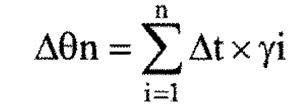


図20は、図15および図16のレーンマーカ推定(S1)に関する別の詳細なフローチャートを示している。図20では、図6に示す第1のレーンマーカ推定手段として、図10、11、14の実施例で述べたように、自車両100が走行している道路の詳細データを記憶しておき、その記憶した詳細データから取得した自車両100の前方レーンマーカの位置点列データとして出力する場合の実施例である。S1-10にて、自車両100の自己位置データを取得する。自己位置は、GPSを用いて自己位置推定する方法に加え、自車両100が走行する走行環境に予め目印となるランドマークを設定し、ランドマークと自車両100の相対距離から自車両100の位置を補正する方法などがある。S1-10にて、自車両100の自己位置が取得できないと、開始へ戻り、自己位置が取得できると、S1-11へ進む。S1-11では、S1-10で取得した自車両100の自己位置データに対応した道路地図データを取得する。道路地図データは、詳細な道路データが格納されており、その一つとして、道路にペイントされているレーンマーカの位置データが格納されている。次に、S1-12へ進み、自車両100の自己位置データに対応した道路地図データにレーンマーカ位置情報が格納されているかを判定する。ここで、レーンマーカ位置データが格納されていないとすると、道路地図データからレーンマーカの位置点列データを取得することができないと判断され、開始へ戻る。一方、S1-12において、レーンマーカ位置データが格納されているとすると、道路地図データからレーンマーカの位置点列データを取得し、自車両100の後方のレーンマーカの位置点列データとして出力する。
図21は、図15、図16に示すフローチャートにおけるレーンマーカ推定値補正(S5)に関する詳細なフローチャートを示している。また、図23は、自車両100とその周辺環境の状況を模式的に示した関係図である。先ず、図23を用いて、自車両100と自車両100が検出する前方レーンマーカの位置点列データ、自車両100が推定する後方レーンマーカの位置点列データ、自車両100が検出する自車両周辺のレーンマーカの位置点列データについて説明する。図23の(A)は、ある時刻における自車両100の位置を示している。図23(A)では、自車両100は、第1のレーンマーカ推定手段610によって自車両100の後方レーンマーカの位置点列データを推定するために、自車両100の前方の領域FF1における前方レーンマーカの位置点列データを検出する。そして、自車両100が図23(B)のように移動した際、図23(A)にて取得した前方レーンマーカの位置点列データは、自車両100の後方領域FF2の位置になる。一方、図23の自車両100は、第2のレーンマーカ検出手段620によって図23(B)に示す自車両100の領域RR2における周辺レーンマーカの位置点列データを検出する。この際、第1のレーンマーカ推定手段610にて取得した後方レーンマーカの位置点列データは、領域FF2にあり、第2のレーンマーカ検出手段620にて取得した周辺レーンマーカの位置点列データは、領域RR2にあり、2つのレーンマーカの位置点列データは、重なる領域MM2を有している。以上のことを踏まえ、図21のフローチャートを説明する。先ず、S5-1では、第1のレーンマーカ推定手段610によって現在の自車両100の後方レーンマーカの位置点列データを取得する。次に、S5-2において、第2のレーンマーカ検出手段620によって周辺レーンマーカの位置点列データを取得する。S5-3では、S5-1において第1のレーンマーカ推定手段610によって取得した現在の自車両100の後方レーンマーカの位置点列データとS5-2において第2のレーンマーカ検出手段620によって取得した周辺レーンマーカの位置点列データの重なる領域(図23の領域MM2)の1つ以上の位置点列データを取得する。そして、S5-4にて、重なる領域(図23の領域MM2)に存在する第2のレーンマーカ検出データである自車両100の周辺のレーンマークの位置点列データと第1のレーンマーカ推定データである自車両100の後方のレーンマーカの位置点列データの距離が最小になるように第1のレーンマーカ推定データである自車両100の後方のレーンマーカの位置点列データ全体を平行・回転移動する。S5-4にて、平行・回転移動された第1のレーンマーカ推定データである自車両100の後方のレーンマーカの位置点列データを自車両100の後方レーンマーカの位置点列データとして出力する(S5-5)。
図22は、図21のフローチャートにおける第1のレーンマーカ推定データである自車両100の後方のレーンマーカの位置点列データ全体を平行・回転移動する処理(S5-4)に関する具体的な処理の一実施例について示した図である。
S5-4-1では、重なる領域MM2の第1のレーンマーカ推定データである自車両100の後方のレーンマーカの位置点列データ{(Rxc_LL1i,Ryc_LL1i)、(Rxc_LR1i,Ryc_LR1i)}を取得する。ここで、Rxc_LL1iは、領域MM2における後方の左レーンマーカのi番目の位置点列データのx軸座標の相対距離、Ryc_LL1iは、領域MM2における後方の左レーンマーカのi番目の位置点列データのy軸座標の相対距離、Rxc_LR1iは、領域MM2における後方の右レーンマーカのi番目の位置点列データのx軸座標の相対距離、Ryc_LR1iは、領域MM2における後方の右レーンマーカのi番目の位置点列データのy軸座標の相対距離を示している。S5-4-2では、重なる領域MM2の第2のレーンマーカ検出データである自車両100の周辺のレーンマーカの位置点列データ{(Rxc_LL2i,Ryc_LL2i)、(Rxc_LR2i,Ryc_LR2i)}を取得する。ここで、Rxc_LL2iは、領域MM2における周辺の左レーンマーカのi番目の位置点列データのx軸座標の相対距離、Ryc_LL2iは、領域MM2における周辺の左レーンマーカのi番目の位置点列データのy軸座標の相対距離、Rxc_LR2iは、領域MM2における周辺の右レーンマーカのi番目の位置点列データのx軸座標の相対距離、Ryc_LR2iは、領域MM2における周辺の右レーンマーカのi番目の位置点列データのy軸座標の相対距離を示している。次に、車両座標系におけるx軸座標の値が原点に近い第2のレーンマーカ検出データである周辺レーンマーカの位置点列データの車両座標系におけるy軸座標の値と車両座標系におけるx軸座標の値が原点に近い第1のレーンマーカ推定データである後方レーンマーカの位置点列データの車両座標系におけるy軸座標の値が同じになるように第1のレーンマーカ推定データである領域FF2の全ての後方レーンマーカの位置点列データの車両座標系におけるy軸座標の値を補正する。次に、S5-4-4にて、領域MM2における第1のレーンマーカ推定データである後方レーンマーカの位置点列データ{(Rxc_LL1i,Ryc_LL1i)、(Rxc_LR1i,Ryc_LR1i)}と領域MM2における第2のレーンマーカ検出データである車両周辺レーンマーカ位置点列データ{(Rxc_LL2i,Ryc_LL2i),(Rxc_LR2i,Ryc_LR2i)}の近い点の間の距離を演算して記憶する。そして、S5-4-5にて、領域FF2の第1のレーンマーカ推定データである後方レーンマーカの位置点列データを車両座標系におけるx軸座標が原点に近い点を中心に所定角度だけ回転変換する。そして、S5-4-6にて、回転変換した領域MM2の第1のレーンマーカ推定データである後方レーンマーカの位置点列データと領域MM2における第2のレーンマーカ検出データである車両周辺レーンマーカ位置点列データの近い点の間の距離を演算する。ここで、前回までに演算した近い点間の距離よりも今回演算した近い点の間の距離の方が小さいか否かを判定する(S5-4-7)。今回演算した距離の方が大きい場合は、S5-4-5へ戻り、今回演算した距離の方が小さい場合は、S5-4-8へ進む。S5-4-8では、回転変換した領域FF2の第1のレーンマーカ推定データである後方レーンマーカの位置点列データを車両周辺のレーンマーカ位置の補正データとして記憶する。そして、S5-4-5で行う回転変換が所定の範囲を超えたか否かを判定する(S5-4-9)。所定の範囲を超えていない場合は、S5-4-5へ戻り、所定の範囲を超えた場合は、終了となる。
図24は、図22にて示したフローチャートによって補正される前の第1のレーンマーカ推定データである後方レーンマーカの位置点列データ(図24(A))と補正された後の第1のレーンマーカ推定データである後方レーンマーカの位置点列データ(図24(B))を示している。図24(A)は、第1のレーンマーカ推定データである後方レーンマーカの位置点列データが補正される前であり、第2のレーンマーカ検出データである車両周辺レーンマーカ位置点列データと第1のレーンマーカ推定データである後方レーンマーカの位置点列データが重なる領域MM2においてずれが生じている。これに対して、図24(B)は、第1のレーンマーカ推定データである後方レーンマーカの位置点列データが補正された後であり、第2のレーンマーカ検出データである車両周辺レーンマーカ位置点列データと第1のレーンマーカ推定データである後方レーンマーカの位置点列データが重なる領域MM2において、ずれが解消されている。補正前の第2のレーンマーカ検出データである車両周辺レーンマーカ位置点列データと第1のレーンマーカ推定データである後方レーンマーカの位置点列データの重なる領域MM2におけるずれは、第1のレーンマーカ推定データである後方レーンマーカの位置点列データを演算する際に、自車両100の車両挙動を用いて変換しているが、変換するために演算した自車両100の移動量や旋回角には誤差が存在するために生じる。図22にて示したフローチャートによる補正を用いることで、変換するために演算した自車両100の移動量や旋回角に誤差が有った場合でも、その誤差を抑制することが可能である。
図25は、自車両100の周辺の移動体が走行する車線を判定するフローチャートを示している。S7-1では、先ず、自車両100が走行する車周辺レーンマーカの情報を取得する。具体的には、自車両100が走行する車線の左右の車線が存在するか否か、存在する場合の左右車線の車線幅の値を取得する。この車線情報は、例えば、画像認識装置80によって自車両100が走行する車線の左右の車線のレーンマーカ位置を検出しても良いし、道路地図データと自車両100の自己位置推定データから現在自車両100が走行している道路の車線数と現在自車両100が走行している車線位置から取得しても良い。次に、S7-1で取得したデータから自車両100が走行している車線の左車線の有無を判定する(S7-2)。ここで、左車線が無いと判定されるとS7-9へ進み、左車線データ無いと設定され、S7-4へ進む。一方、左車線があると判定されるとS7-3へ進み、図6のレーンマーカ推定値補正手段640によって補正された自車両100の後方レーンマーカの位置点列データから現在の自車両100が走行する車線の周辺レーンマーカの位置点列データを取得し、自車両100が走行する左レーンマーカの位置点列データに左車線の車線幅を加えることで、左車線の左側レーンマーカの位置点列データを設定する。次に、S7-4へ進み、S7-1で取得したデータから自車両100が走行している車線の右車線の有無を判定する。ここで、右車線が無いと判定されるとS7-10へ進み、右車線データ無いと設定され、S7-6へ進む。一方、右車線があると判定されるとS7-5へ進み、図6のレーンマーカ推定値補正手段640によって補正された自車両100の後方レーンマーカの位置点列データから現在の自車両100が走行する車線の周辺レーンマーカの位置点列データを取得し、自車両100が走行する右レーンマーカの位置点列データに右車線の車線幅を加えることで、右車線の右側レーンマーカの位置点列データを設定する。次に、S7-6進み、周辺移動体検出手段630によって自車両100の周辺移動体の位置を取得する。S7-7にて、自車両100の周辺移動体の存在の有無を判定し、周辺移動体が存在しない場合は終了し、周辺移動体が存在する場合は、S7-8へ進む。S7-8では、自車両100が走行する自車線の左右レーンマーカの位置点列データであるレーンマーカ推定値補正手段640によって補正された自車両100の後方レーンマーカの位置点列データとS7-3、S7-5で設定した左車線の左レーンマーカの点列位置データおよび右車線の右レーンマーカの点列位置データと移動体の位置データから移動体が走行する車線を判定し、各移動体が走行する車線の情報を出力する。
図26は、図25に示したフローチャートのS7-8にて行う自車両100の周辺移動体の走行車線の判定について説明する一実施例の図である。図26において、(A)は、曲線を描く道路の中央車線を走行する自車両100とその後方で自車両100の右車線を走行する車両200と自車両100と同じ車線を走行する車両400が存在している走行シーンを示している。図26(B)は、図26(A)の走行シーンに関して、自車両100の車両座標系によって後方レーンマーカの位置点列データと移動体の位置を表現した図である。図26(B)の車両400近傍を拡大した図が図26(C)である。自車両100の後方レーンマーカの位置点列データの中で車両400の近傍に位置する左レーンマーカの位置点列データをLMP-L1、LMP-L2とし、車両400の近傍に位置する右レーンマーカの位置点列データをLMP-R1、LMP-R2とする。また、左レーンマーカの位置点列データをLMP-L1、LMP-L2を直線近似した際に車両400のx軸座標の値と同じ点を400-L、右レーンマーカの位置点列データをLMP-R1、LMP-R2を直線近似した際に車両400のx軸座標の値と同じ点を400-Rとする。
図27は、図25に示したフローチャートのS7-8にて行う自車両100の周辺移動体の走行車線の判定に関する詳細なフローチャートを示した図である。図27のフローチャートを図26に示した関係を用いて説明する。先ず、S7-9-1にて、周辺移動体400のx軸座標(車両座標系)の前後の最も近い左右レーンマーカ推定データの位置点列データを2点取得する。この位置点列データは、図26に示すLMP-L1とLMP-L2およびLMP-R1とLMP-R2を示している。次に、S7-9-2にて、取得した左右のレーンマーカの2点の位置データ(LMP-L1とLMP-L2およびLMP-R1とLMP-R2)から周辺移動体400のx軸座標(車両座標系)と同じ左右のレーンマーカ位置のy軸座標の値を推定する。これは、図26に示す400-Lと400-Rの位置の値である。周辺移動体400のx軸座標(車両座標系)と同じ左右のレーンマーカ位置のy軸座標の値を求める具体的な方法には、次のような方法がある。
LMP-L1の座標を(Rxa_LL1、Rya_LL1)、LMP-L2の座標を(Rxa_LL2、Rya_LL2)、LMP-R1の座標を(Rxa_LR1、Rya_LR1)、LMP-R2の座標を(Rxa_LR2、Rya_LR2)、周辺移動体400のx軸座標をRxaとすると、同じx軸座標の値をもつ左右のレーンマーカ位置のy軸座標(Ry_LJdge、 Ry_RJdge)は、次の式で求めることができる。


同様に、自車両100の走行する車線の左車線の左側レーンマーカに関して、周辺移動体400のx軸座標同じx軸座標の値をもつ左車線の左側レーンマーカ位置のy軸座標(Ry_nLJdge)は、次の式で求めることができる。

また、自車両100の走行する車線の右車線の右側レーンマーカに関して、周辺移動体400のx軸座標同じx軸座標の値をもつ右車線の右側レーンマーカ位置のy軸座標(Ry_nRJdge)は、次の式で求めることができる。

なお、周辺移動体400のx軸座標(車両座標系)の前後の最も近い左車線の左側レーンマーカの位置点列データの座標を(Rxa_nLL1、Rya_nLL1)、(Rxa_nLL2、Rya_nLL2)とし、周辺移動体400のx軸座標(車両座標系)の前後の最も近い右車線の右側レーンマーカの位置点列データの座標を(Rxa_nLR1、Rya_nLR1)、(Rxa_nLR2、Rya_nLR2)とする。
次に、S7-9-3では、周辺移動体400のy軸座標(車両座標系)の値(Rya)とS7-9-2で推定した左右のレーンマーカの位置のy軸座標の値(Ry_LJdge、Ry_RJdge)、左車線の左側レーンマーカの位置のy軸座標の値(Ry_nLJdge)および、右車線の右側レーンマーカの位置のy軸座標の値(Ry_nRJdge)の大小関係から移動体400が走行する車線を判定する。具体的には、次のような判定が可能となる。
1.(Rya < Ry_Ljdge)かつ(Rya > Ry_Rjdge)の場合は、
移動体400は、自車両100と同じ車線を走行している。
移動体400は、自車両100と同じ車線を走行している。
2.(Rya < Ry_nLjdge)かつ(Rya ≧ Ry_Ljdge)の場合は、
移動体400は、自車両100の左隣接車線を走行している。
移動体400は、自車両100の左隣接車線を走行している。
3.(Ry_nRjdge < Rya)かつ(Ry_Rjdge ≧ Rya)の場合は、
移動体400は、自車両100の右隣接車線を走行している。
移動体400は、自車両100の右隣接車線を走行している。
図28は、本発明によって、自車両100の前方レーンマーカの位置点列データを用いて自車両100の後方レーンマーカの位置点列データを推定した結果の一例を示している。図28に示すグラフの原点は、自車両100の位置を示している。横軸方向は、自車両100の進行方向を示しており、縦軸方向は、自車両100の進行方向に対して直角となる横方向を示している。図28において、白丸は、自車両100の前方レーンマーカの検出値の位置点列データであり、黒丸が自車両100周辺のレーンマーカの検出値の位置点列データであり、四角が前方レーンマーカの検出値の位置点列データから後方レーンマーカの位置点列データを推定した第1のレーンマーカ推定値の位置点列データであり、△が第1のレーンマーカ推定値の位置点列データを自車両100周辺のレーンマーカの検出値の位置点列データで補正した補正後の後方レーンマーカ推定値の位置点列データである。また、点線が実際のレーンマーカ位置を示している。この結果から分かるように、本発明によって、自車両100の後方レーンマーカの位置をより正確に推定することが可能となる。
図29と図30に、本発明にて推定した自車両100の周辺環境認識結果をモニタに表示した実施例について説明する。図29は、表示装置660のモニタ上に自車両100の位置を原点として、自車両100の進行方向をx軸座標の正とし、x軸座標に垂直で自車両の左側を正とした横方向をy軸座標で表現している。表示装置660のモニタ上には、自車両100と自車両100の周辺のレーンマーカ(LM1、LM2、LM3、LM4)の位置点列データを白丸と線によって表示しており、自車両100の周辺に存在する移動体200、400の位置も表示している。この表示によって、自車両100の周辺に存在する移動体が自車両100の走行している車線に対して、どの車線にいるかを確認することができる。このような周辺環境認識装置60が判定した結果を表示することでドライバへ通知することによって、周辺環境認識装置60による判定結果をドライバが理解することができ、ドライバに安心感を与えるという効果を得ることが可能となる。また、図30では、例えば、画像認識装置80-1が自車両100の右側のレーンマーカを認識できなかった場合の表示の一例を示している。この場合、右側のレーンマーカを検出できず、後方のレーンマーカの位置点列データを推定することができなくなる。このように後方のレーンマーカが推定できない場合は、例えば、左側レーンマーカの位置点列データと車線幅の値から右側のレーンマーカを推定することも可能である。しかし、右側のレーンマーカの位置点列データの信頼性は低くなるため、右側のレーンマーカの位置点列データを左側のレーンマーカの位置点列データの表示とは異なるように、白丸と点線で表現する。また、右側のレーンマーカの位置点列データの信頼性が低いことを表示すると良い。
図31は、本発明の周辺環境認識装置60と車両制御装置40内に構成される車線変更制御手段41によって行われる車線変更制御に関する一つの実施例を示している。図31に示すように、車両制御装置40は、車線変更要求に応じて自車両100が現在走行している車線から異なる車線へ車線変更を行う制御指令を出力する車線変更制御手段41を有している。車線変更制御手段41は、車線変更要求判定手段411、自車両目標軌道設定手段412、移動体軌道推定手段413、衝突可能性判定手段414、制御指令演算手段415から構成される。車線変更要求判定手段411は、ドライバによる車線変更操作(例えば、ウインカ操作など)あるいは車両制御装置40の別の構成要素で決定した自車両100の走行計画から、自車両100が現在走行している車線から別の車線へ変更する要求があるかを判定する。車線変更要求手段411で車線変更要求があると判定されると、車線変更要求出力は、自車両目標軌道設定手段412、移動体軌道推定手段413へ出力される。自車両目標軌道設定手段412では、自車両100が車線変更時に走行する目標軌道を設定する。目標軌道設定は、前記の車両100の走行計画から目標軌道を設定しても良い。具体的には、図32に示すように、車線変更時に自車両100が走行する目標軌道を自車両100の前方の道路および車線上の位置を点列(100-1、100-2、100-3、100-4、100-5)で表現するなどがある。移動体軌道推定手段413では、周辺環境認識装置60から出力される自車両100の周辺の移動体200の相対位置と相対速度、移動体が走行する車線L3の情報を取得し、移動体の走行軌道を推定する。具体的には、図32に示すように移動体200が現在走行している車線L3に沿って移動体200は継続的に走行し、移動体200が現在の相対速度で走行する場合における所定時間後に到達する移動体200の複数の相対位置(200-1、200-2、200-3、200-4、200-5)の点列を出力する。衝突可能性判定手段414は、車線変更時の自車両100が走行する目標軌道の位置点列(100-1、100-2、100-3、100-4、100-5)を自車両目標軌道設定手段412から取得し、移動体200の所定時間後に到達する複数の位置点列(200-1、200-2、200-3、200-4、200-5)を移動体軌道推定手段413から取得し、自車両100と移動体200の所定時間後の位置から衝突可能性を判定する。具体的には、所定時間後の同一時刻における自車両100と移動体200の位置が所定の距離以内に有る場合は、自車両100と移動体200は衝突する可能性があると判定し、所定の距離よりも大きく離れている場合は、衝突する可能性が低いと判定する。制御指令演算手段415は、衝突可能性判定手段414にて衝突可能性があると判定すると、衝突を回避するための制御指令を演算する。制御指令演算手段415で演算された制御指令は、車両制御装置40の車両挙動制御装置42へ出力され、車両挙動制御装置42は最終的な車両制御装置の指令を演算する。本実施例では、1つの移動体200の場合について説明しているが、複数の移動体が存在する場合でも同様に処理することができる。
図31、32に示した実施例によれば、自車両100の周辺の移動体200とレーンマーカの位置を認識することで、自車両100の周辺移動体200が走行する車線も同時に判定することができるため、所定時間後の周辺移動体200の位置をより正しく推定することができる。この結果、周辺環境認識装置60を搭載した自車両100は、信頼性の高い自車両100と周辺移動体200が衝突可能性を判定することが可能となる効果がある。
なお、本発明の実施形態は、以下の態様であってもよい。
(1)少なくとも自車両の周辺の道路情報を検知する車両周辺認識手段を有する車両の周辺環境認識システムにおいて、
前記自車両の後方レーンマーカ位置を推定する第1のレーンマーカ推定手段と、
前記車両周辺認識手段で検知した前記自車両の近傍レーンマーカ位置を出力する第2のレーンマーカ検出手段と、
前記第2のレーンマーカ検出手段が出力するレーンマーカ位置に基づいて、前記第1のレーンマーカ推定手段が出力する前記自車両の後方レーンマーカ位置を補正するレーンマーカ推定値補正手段を有する周辺環境認識システム。
(2)少なくとも自車両の近傍の道路情報を検知する車両周辺認識手段と、前記自車両の前方の道路状態を検知する車両前方認識手段と、自車両の挙動を検知する車両挙動検出手段を有する車両の周辺環境認識システムにおいて、
前記車両前方認識手段で検知した前記自車両の前方レーンマーカ位置と前記車両挙動検出手段で求めた前記自車両の移動変化量から前記自車両の後方レーンマーカ位置を推定し、該推定した後方レーンマーカ位置を出力する第1のレーンマーカ推定手段と、
前記車両周辺認識手段で検知した前記自車両の近傍レーンマーカ位置を出力する第2のレーンマーカ検出手段と、
前記第2のレーンマーカ検出手段が出力する前記自車両の周辺レーンマーカ位置に基づいて、前記第1のレーンマーカ推定位置を補正し、該補正した前記自車両の後方レーンマーカ推定位置の補正結果を出力するレーンマーカ推定値補正手段と、を有する周辺環境認識システム。
(3)少なくとも自車両の周辺の道路情報を検知する車両周辺画像認識手段と、前記自車両の周辺の移動体・障害物を検知する車両周辺移動体認識手段を有する周辺環境認識システムであって、
前記車両周辺画像認識手段によって前記自車両の近傍の道路情報であるレーンマーカの位置を検知する第2のレーンマーカ検出手段と、
前記車両周辺画像認識手段によって取得した道路情報に基づいて、前記自車両の後方のレーンマーカの位置を推定する第1のレーンマーカ推定手段と、
前記第2のレーンマーカ検出手段によって取得した前記自車両の近傍のレーンマーカの位置情報に基づいて前記第1のレーンマーカ推定手段によって取得した前記自車両の後方のレーンマーカの位置を補正するレーンマーカ推定値補正手段と、を有する周辺環境認識システム。
(4)少なくとも自車両の周辺の道路情報を検知する車両周辺画像認識手段と、前記自車両の周辺の移動体・障害物を検知する車両周辺移動体認識手段と、前記自車両の挙動を推定する車両挙動手段を有する周辺環境認識システムであって、
前記車両周辺画像認識手段によって前記自車両の近傍の道路情報であるレーンマーカの位置を検知する第2のレーンマーカ検出手段と、
前記周辺画像認識手段によって検出した前記自車両の前方のレーンマーカと前記車両挙動手段で推定した前記自車両の移動量と旋回角に基づいて前記自車両の後方のレーンマーカの位置を推定する第1のレーンマーカ推定手段と、
前記第2のレーンマーカ検出手段によって取得した前記自車両の近傍のレーンマーカの位置情報に基づいて前記第1のレーンマーカ推定手段によって取得した前記自車両の後方のレーンマーカの位置を補正するレーンマーカ推定値補正手段と、を有する周辺環境認識システム。
(5)少なくとも自車両周辺の道路情報を検知する車両周辺認識手段と前記自車両の周辺の移動体を検知する周辺移動体検出手段を有する車両の周辺環境認識システムにおいて、
前記自車両の後方レーンマーカ位置を推定する第1のレーンマーカ推定手段と、
前記車両周辺認識手段で検知した前記自車両の近傍レーンマーカ位置を出力する第2のレーンマーカ検出手段と、
前記第2のレーンマーカ検出手段が出力するレーンマーカ位置に基づいて、前記第1のレーンマーカ推定手段が出力する前記自車両の後方レーンマーカ位置を補正するレーンマーカ推定値補正手段と、
前記レーンマーカ推定値補正手段によって取得した自車両の後方のレーンマーカの位置と前記周辺移動体検出手段によって取得した前記自車両の周辺の移動体の位置から前記周辺移動体検出手段によって取得した前記自車両の周辺の移動体が存在する車線を判定する周辺移動体判定手段と、
該周辺移動体判定手段によって判定した前記自車両の周辺の移動体が存在する車線を通知する通知手段あるいは、表示する表示装置とを有する周辺環境認識システム。
(6)少なくとも自車両の近傍の道路情報を検知する車両周辺認識手段と、前記自車両の前方の道路状態を検知する車両前方認識手段と、前記自車両の周辺の移動体を検知する周辺移動体検出手段と、自車両の挙動を検知する車両挙動検出手段を有する車両の周辺環境認識システムにおいて、
前記車両前方認識手段で検知した前記自車両の前方レーンマーカ位置と前記車両挙動検出手段で求めた前記自車両の移動変化量から前記自車両の後方レーンマーカ位置を推定し、該推定した後方レーンマーカ位置を出力する第1のレーンマーカ推定手段と、
前記車両周辺認識手段で検知した前記自車両の近傍レーンマーカ位置を出力する第2のレーンマーカ検出手段と、
前記第2のレーンマーカ検出手段が出力する前記自車両の周辺レーンマーカ位置に基づいて、前記第1のレーンマーカ推定位置を補正し、該補正した前記自車両の後方レーンマーカ推定位置の補正結果を出力するレーンマーカ推定値補正手段と、
前記レーンマーカ推定値補正手段によって取得した自車両の後方のレーンマーカの位置と前記周辺移動体検出手段によって取得した前記自車両の周辺の移動体の位置から前記周辺移動体検出手段によって取得した前記自車両の周辺の移動体が存在する車線を判定する周辺移動体判定手段と、
該周辺移動体判定手段によって判定した前記自車両の周辺の移動体が存在する車線を通知する通知手段あるいは、表示する表示装置とを有する周辺環境認識システム。
(7)少なくとも自車両の周辺の道路情報を検知する車両周辺画像認識手段と、前記自車両の周辺の移動体・障害物を検知する車両周辺移動体認識手段を有する周辺環境認識システムであって、
前記車両周辺画像認識手段によって前記自車両の近傍の道路情報であるレーンマーカの位置を検知する第2のレーンマーカ検出手段と、
前記車両周辺画像認識手段によって取得した道路情報に基づいて、前記自車両の後方のレーンマーカの位置を推定する第1のレーンマーカ推定手段と、
前記第2のレーンマーカ検出手段によって取得した前記自車両の近傍のレーンマーカの位置情報に基づいて前記第1のレーンマーカ推定手段によって取得した前記自車両の後方のレーンマーカの位置を補正するレーンマーカ推定値補正手段と、
前記レーンマーカ推定値補正手段によって取得した自車両の後方のレーンマーカの位置と前記周辺移動体検出手段によって取得した前記自車両の周辺の移動体の位置から前記周辺移動体検出手段によって取得した前記自車両の周辺の移動体が存在する車線を判定する周辺移動体判定手段と、
該周辺移動体判定手段によって判定した前記自車両の周辺の移動体が存在する車線を通知する通知手段あるいは、表示する表示装置とを有する周辺環境認識システム。
(8)少なくとも自車両の周辺の道路情報を検知する車両周辺画像認識手段と、前記自車両の周辺の移動体・障害物を検知する車両周辺移動体認識手段と、前記自車両の挙動を推定する車両挙動手段を有する周辺環境認識システムであって、
前記車両周辺画像認識手段によって前記自車両の近傍の道路情報であるレーンマーカの位置を検知する第2のレーンマーカ検出手段と、
前記周辺画像認識手段によって検出した前記自車両の前方のレーンマーカと前記車両挙動手段で推定した前記自車両の移動量と旋回角に基づいて前記自車両の後方のレーンマーカの位置を推定する第1のレーンマーカ推定手段と、
前記第2のレーンマーカ検出手段によって取得した前記自車両の近傍のレーンマーカの位置情報に基づいて前記第1のレーンマーカ推定手段によって取得した前記自車両の後方のレーンマーカの位置を補正するレーンマーカ推定値補正手段と、
前記レーンマーカ推定値補正手段によって取得した自車両の後方のレーンマーカの位置と前記周辺移動体検出手段によって取得した前記自車両の周辺の移動体の位置から前記周辺移動体検出手段によって取得した前記自車両の周辺の移動体が存在する車線を判定する周辺移動体判定手段と、
該周辺移動体判定手段によって判定した前記自車両の周辺の移動体が存在する車線を通知する通知手段あるいは、表示する表示装置とを有する周辺環境認識システム。
(9)少なくとも自車両周辺の道路情報を検知する車両周辺認識手段と前記自車両の周辺の移動体を検知する周辺移動体検出手段を有する車両の周辺環境認識システムにおいて、
前記自車両の後方レーンマーカ位置を推定する第1のレーンマーカ推定手段と、
前記車両周辺認識手段で検知した前記自車両の近傍レーンマーカ位置を出力する第2のレーンマーカ検出手段と、
前記第2のレーンマーカ検出手段が出力するレーンマーカ位置に基づいて、前記第1のレーンマーカ推定手段が出力する前記自車両の後方レーンマーカ位置を補正するレーンマーカ推定値補正手段と、
前記レーンマーカ推定値補正手段によって取得した自車両の後方のレーンマーカの位置と前記周辺移動体検出手段によって取得した前記自車両の周辺の移動体の位置から前記周辺移動体検出手段によって取得した前記自車両の周辺の移動体が存在する車線を判定する周辺移動体判定手段と、
前記自車両が現在走行する車線から左右いずれかの隣の車線へ変更することを判定し、前記周辺移動体判定手段によって判定された移動体が前記自車両が変更する車線内に存在する場合に、前記自車両と前記移動体との衝突可能性を判定して、衝突可能性がある場合は、警報を出力する警報装置とを有する周辺環境認識システム。
(10)少なくとも自車両の近傍の道路情報を検知する車両周辺認識手段と、前記自車両の前方の道路状態を検知する車両前方認識手段と、前記自車両の周辺の移動体を検知する周辺移動体検出手段と、自車両の挙動を検知する車両挙動検出手段を有する車両の周辺環境認識システムにおいて、
前記車両前方認識手段で検知した前記自車両の前方レーンマーカ位置と前記車両挙動検出手段で求めた前記自車両の移動変化量から前記自車両の後方レーンマーカ位置を推定し、該推定した後方レーンマーカ位置を出力する第1のレーンマーカ推定手段と、
前記車両周辺認識手段で検知した前記自車両の近傍レーンマーカ位置を出力する第2のレーンマーカ検出手段と、
前記第2のレーンマーカ検出手段が出力する前記自車両の周辺レーンマーカ位置に基づいて、前記第1のレーンマーカ推定位置を補正し、該補正した前記自車両の後方レーンマーカ推定位置の補正結果を出力するレーンマーカ推定値補正手段と、
前記レーンマーカ推定値補正手段によって取得した自車両の後方のレーンマーカの位置と前記周辺移動体検出手段によって取得した前記自車両の周辺の移動体の位置から前記周辺移動体検出手段によって取得した前記自車両の周辺の移動体が存在する車線を判定する周辺移動体判定手段と、
前記自車両が現在走行する車線から左右いずれかの隣の車線へ変更することを判定し、前記周辺移動体判定手段によって判定された移動体が前記自車両が変更する車線内に存在する場合に、前記自車両と前記移動体との衝突可能性を判定して、衝突可能性がある場合は、警報を出力する警報装置とを有する周辺環境認識システム。
(11)少なくとも自車両の周辺の道路情報を検知する車両周辺画像認識手段と、前記自車両の周辺の移動体・障害物を検知する車両周辺移動体認識手段を有する周辺環境認識システムであって、
前記車両周辺画像認識手段によって前記自車両の近傍の道路情報であるレーンマーカの位置を検知する第2のレーンマーカ検出手段と、
前記車両周辺画像認識手段によって取得した道路情報に基づいて、前記自車両の後方のレーンマーカの位置を推定する第1のレーンマーカ推定手段と、
前記第2のレーンマーカ検出手段によって取得した前記自車両の近傍のレーンマーカの位置情報に基づいて前記第1のレーンマーカ推定手段によって取得した前記自車両の後方のレーンマーカの位置を補正するレーンマーカ推定値補正手段と、
前記レーンマーカ推定値補正手段によって取得した自車両の後方のレーンマーカの位置と前記周辺移動体検出手段によって取得した前記自車両の周辺の移動体の位置から前記周辺移動体検出手段によって取得した前記自車両の周辺の移動体が存在する車線を判定する周辺移動体判定手段と、
前記自車両が現在走行する車線から左右いずれかの隣の車線へ変更することを判定し、前記周辺移動体判定手段によって判定された移動体が前記自車両が変更する車線内に存在する場合に、前記自車両と前記移動体との衝突可能性を判定して、衝突可能性がある場合は、警報を出力する警報装置とを有する周辺環境認識システム。
(12)少なくとも自車両の周辺の道路情報を検知する車両周辺画像認識手段と、前記自車両の周辺の移動体・障害物を検知する車両周辺移動体認識手段と、前記自車両の挙動を推定する車両挙動手段を有する周辺環境認識システムであって、
前記車両周辺画像認識手段によって前記自車両の近傍の道路情報であるレーンマーカの位置を検知する第2のレーンマーカ検出手段と、
前記周辺画像認識手段によって検出した前記自車両の前方のレーンマーカと前記車両挙動手段で推定した前記自車両の移動量と旋回角に基づいて前記自車両の後方のレーンマーカの位置を推定する第1のレーンマーカ推定手段と、
前記第2のレーンマーカ検出手段によって取得した前記自車両の近傍のレーンマーカの位置情報に基づいて前記第1のレーンマーカ推定手段によって取得した前記自車両の後方のレーンマーカの位置を補正するレーンマーカ推定値補正手段と、
前記レーンマーカ推定値補正手段によって取得した自車両の後方のレーンマーカの位置と前記周辺移動体検出手段によって取得した前記自車両の周辺の移動体の位置から前記周辺移動体検出手段によって取得した前記自車両の周辺の移動体が存在する車線を判定する周辺移動体判定手段と、
前記自車両が現在走行する車線から左右いずれかの隣の車線へ変更することを判定し、前記周辺移動体判定手段によって判定された移動体が前記自車両が変更する車線内に存在する場合に、前記自車両と前記移動体との衝突可能性を判定して、衝突可能性がある場合は、警報を出力する警報装置とを有する周辺環境認識システム。
上記(3)(4)(7)(8)(11)(12)における第2のレーンマーカ検出手段へ提供する前記自車両の周辺のレーンマーカを検出する前記車両周辺画像認識手段が、前記自車両の前方、右側方、左側方、後方の路面の画像を取得し、レーンマーカを認識する全周囲認識カメラである周辺環境認識システム。
上記(3)(4)(7)(8)(11)(12)における第2のレーンマーカ検出手段へ提供する前記自車両の周辺のレーンマーカを検出する前記車両周辺画像認識手段が、前記自車両の右側方、左側方の路面の画像を取得し、レーンマーカを認識する自車両の側方認識カメラである周辺環境認識システム。
上記(3)(4)(7)(8)(11)(12)における第2のレーンマーカ検出手段へ提供する前記自車両の周辺のレーンマーカを検出する前記車両周辺画像認識手段が、前記自車両の後方の路面の画像を取得し、レーンマーカを認識する自車両後方認識カメラである周辺環境認識システム。
上記(3)(4)(7)(8)(11)(12)における第2のレーンマーカ検出手段へ提供する前記自車両の周辺のレーンマーカを検出する前記車両周辺画像認識手段が、前記自車両の前方、右側方と左側方、後方の路面の画像を取得し、レーンマーカを認識する全周囲認識カメラの何れかの画像認識結果であり、前記全周囲認識カメラの中で機能している画像認識結果を優先して利用する周辺環境認識システム
上記(3)(4)(7)(8)(11)(12)における第1のレーンマーカ推定手段へ提供するレーンマーカを検出する前記車両周辺画像認識手段が、前記自車両の前方の画像を取得し、レーンマーカを認識する前方認識カメラである周辺環境認識システム。
上記(3)(4)(7)(8)(11)(12)における第1のレーンマーカ推定手段へ提供するレーンマーカを検出する前記車両周辺画像認識手段が、前記自車両の前方の画像を取得し、レーンマーカを認識する前方ステレオカメラである周辺環境認識システム。
上記(3)(4)(7)(8)(11)(12)における第1のレーンマーカ推定手段へ提供するレーンマーカを検出する前記車両周辺画像認識手段が、前記自車両の右側方と左側方の画像を取得し、レーンマーカを認識する自車両側方認識カメラである周辺環境認識システム。
上記(3)(4)(7)(8)(11)(12)における第1のレーンマーカ推定手段へ提供するレーンマーカを検出する前記車両周辺画像認識手段が、前記自車両の前方の画像を取得してレーンマーカを認識する前方ステレオカメラ、あるいは前記自車両の右側方と左側方の画像を取得してレーンマーカを認識する自車両側方認識カメラの何れかである周辺環境認識システム。
上記(1)(2)(5)(6)(9)(10)における第1のレーンマーカ推定手段は、前記自車両の位置と進行方向に対応した道路地図データから取得したレーンマーカ位置を用いて、前記自車両の後方のレーンマーカ位置を推定する周辺環境認識システム。
上記(7)~(21)における前記周辺移動体判定手段によって判定した前記自車両の周辺の移動体と該移動体の存在する車線を表示する表示装置は、前記車両周辺画像認識手段から前記第1のレーンマーカ推定手段へレーンマーカの検出結果が出力されない場合は、自車両位置と後方周辺車両位置のみを表示する周辺環境認識システム
上記(7)~(21)における前記周辺移動体判定手段によって判定した前記自車両の周辺の移動体と該移動体の存在する車線を表示する表示装置は、前記車両周辺画像認識手段から第2のレーンマーカ検出手段へ前記自車両の近傍の道路情報であるレーンマーカ検出結果が出力されない場合の前記自車両の後方レーンマーカの表示と前記車両周辺画像認識手段から第2のレーンマーカ検出手段へ前記自車両の近傍の道路情報であるレーンマーカ検出結果が出力される場合の前記自車両の後方レーンマーカの表示を異なる表示にする周辺環境認識システム。
少なくとも車両の車線変更要求を検出して、前記車両の車線変更を行う車線変更制御装置と、上記(1)~(24)の何れかに記載された周辺環境認識装置とを搭載した車両制御装置。
少なくとも車両の車線変更要求を検出して、前記車両の車線変更を行う車線変更制御装置を有する車両において、上記(1)~(24)の何れかに記載された周辺環境認識装置とを搭載した車両。
10 原動機
20 変速機
30 原動機制御装置
40 車両制御装置
50 通信装置
60 周辺環境認識装置
80-1 画像認識装置
80-2 画像認識装置
80-3 画像認識装置
80-4 画像認識装置
90 制動装置
100 車両、自車両
110 警報装置
120 表示装置
130-1 右後方認識装置
130-2 左後方認識装置
130-3 右前方認識装置
130-4 左前方認識装置
200 自車両周辺の移動体
300 自車両周辺の移動体
400 自車両周辺の移動体
610 第1のレーンマーカ推定手段
620 第2のレーンマーカ検出手段
630 周辺移動体検出手段
640 レーンマーカ推定値補正手段
650 周辺移動体判定手段
660 表示装置
670 通知手段
800 レーンマーカ検出手段
Claims (13)
- 少なくとも自車両の周辺の道路情報を検知する車両周辺認識手段を有する車両の周辺環境認識システムにおいて、
前記自車両の後方レーンマーカ位置を推定する第1のレーンマーカ推定手段と、
前記車両周辺認識手段で検知した前記自車両の近傍レーンマーカ位置を出力する第2のレーンマーカ検出手段と、
前記第2のレーンマーカ検出手段が出力するレーンマーカ位置に基づいて、前記第1のレーンマーカ推定手段が出力する前記自車両の後方レーンマーカ位置を補正するレーンマーカ推定値補正手段を有することを特徴とする周辺環境認識システム。 - 前記自車両の前方の道路状態を検知する車両前方認識手段と、
自車両の挙動を検知する車両挙動検出手段と、を有し、
前記第1のレーンマーカ推定手段は、前記車両前方認識手段で検知した前記自車両の前方レーンマーカ位置と前記車両挙動検出手段で求めた前記自車両の移動変化量から前記自車両の後方レーンマーカ位置を推定することを特徴とする請求項1記載の周辺環境認識システム。 - 前記自車両の周辺の移動体・障害物を検知する車両周辺移動体認識手段を有し、
前記第1のレーンマーカ推定手段は、前記車両周辺画像認識手段によって取得した道路情報に基づいて、前記自車両の後方のレーンマーカの位置を推定し、
前記第2のレーンマーカ検出手段は、前記車両周辺画像認識手段によって前記自車両の近傍の道路情報であるレーンマーカの位置を検知しと、
前記レーンマーカ推定値補正手段は、前記第2のレーンマーカ検出手段によって取得した前記自車両の近傍のレーンマーカの位置情報に基づいて前記第1のレーンマーカ推定手段によって取得した前記自車両の後方のレーンマーカの位置を補正することを特徴とする請求項1記載の周辺環境認識システム。 - 前記自車両の周辺の移動体・障害物を検知する車両周辺移動体認識手段と、
前記自車両の挙動を推定する車両挙動手段と、を有し、
前記第1のレーンマーカ推定手段は、前記周辺画像認識手段によって検出した前記自車両の前方のレーンマーカと前記車両挙動手段で推定した前記自車両の移動量と旋回角に基づいて前記自車両の後方のレーンマーカの位置を推定し、
前記第2のレーンマーカ検出手段は、前記車両周辺画像認識手段によって前記自車両の近傍の道路情報であるレーンマーカの位置を検知し、
前記レーンマーカ推定値補正手段は、前記第2のレーンマーカ検出手段によって取得した前記自車両の近傍のレーンマーカの位置情報に基づいて前記第1のレーンマーカ推定手段によって取得した前記自車両の後方のレーンマーカの位置を補正すると、を有することを特徴とする請求項1記載の周辺環境認識システム。 - 前記自車両の周辺の移動体を検知する周辺移動体検出手段と、
前記レーンマーカ推定値補正手段によって取得した自車両の後方のレーンマーカの位置と前記周辺移動体検出手段によって取得した前記自車両の周辺の移動体の位置から前記周辺移動体検出手段によって取得した前記自車両の周辺の移動体が存在する車線を判定する周辺移動体判定手段と、
該周辺移動体判定手段によって判定した前記自車両の周辺の移動体が存在する車線を通知する通知手段あるいは、表示する表示装置と、を有することを特徴とする請求項1記載の周辺環境認識システム。 - 前記自車両の前方の道路状態を検知する車両前方認識手段と、
前記レーンマーカ推定値補正手段によって取得した自車両の後方のレーンマーカの位置と前記周辺移動体検出手段によって取得した前記自車両の周辺の移動体の位置から前記周辺移動体検出手段によって取得した前記自車両の周辺の移動体が存在する車線を判定する周辺移動体判定手段と、
該周辺移動体判定手段によって判定した前記自車両の周辺の移動体が存在する車線を通知する通知手段あるいは、表示する表示装置と、を有することを特徴とする請求項2記載の周辺環境認識システム。 - 前記レーンマーカ推定値補正手段によって取得した自車両の後方のレーンマーカの位置と前記周辺移動体検出手段によって取得した前記自車両の周辺の移動体の位置から前記周辺移動体検出手段によって取得した前記自車両の周辺の移動体が存在する車線を判定する周辺移動体判定手段と、
該周辺移動体判定手段によって判定した前記自車両の周辺の移動体が存在する車線を通知する通知手段あるいは、表示する表示装置と、を有することを特徴とする請求項3記載の周辺環境認識システム。 - 前記レーンマーカ推定値補正手段によって取得した自車両の後方のレーンマーカの位置と前記周辺移動体検出手段によって取得した前記自車両の周辺の移動体の位置から前記周辺移動体検出手段によって取得した前記自車両の周辺の移動体が存在する車線を判定する周辺移動体判定手段と、
該周辺移動体判定手段によって判定した前記自車両の周辺の移動体が存在する車線を通知する通知手段あるいは、表示する表示装置と、を有することを特徴とする請求項4記載の周辺環境認識システム。 - 前記自車両の周辺の移動体を検知する周辺移動体検出手段と、
前記レーンマーカ推定値補正手段によって取得した自車両の後方のレーンマーカの位置と前記周辺移動体検出手段によって取得した前記自車両の周辺の移動体の位置から前記周辺移動体検出手段によって取得した前記自車両の周辺の移動体が存在する車線を判定する周辺移動体判定手段と、
前記自車両が現在走行する車線から左右いずれかの隣の車線へ変更することを判定し、前記周辺移動体判定手段によって判定された移動体が前記自車両が変更する車線内に存在する場合に、前記自車両と前記移動体との衝突可能性を判定して、衝突可能性がある場合は、警報を出力する警報装置とを有することを特徴とする請求項1記載の周辺環境認識システム。 - 前記自車両の前方の道路状態を検知する車両前方認識手段と、
前記レーンマーカ推定値補正手段によって取得した自車両の後方のレーンマーカの位置と前記周辺移動体検出手段によって取得した前記自車両の周辺の移動体の位置から前記周辺移動体検出手段によって取得した前記自車両の周辺の移動体が存在する車線を判定する周辺移動体判定手段と、
前記自車両が現在走行する車線から左右いずれかの隣の車線へ変更することを判定し、前記周辺移動体判定手段によって判定された移動体が前記自車両が変更する車線内に存在する場合に、前記自車両と前記移動体との衝突可能性を判定して、衝突可能性がある場合は、警報を出力する警報装置と、を有することを特徴とする請求項2記載の周辺環境認識システム。 - 前記レーンマーカ推定値補正手段によって取得した自車両の後方のレーンマーカの位置と前記周辺移動体検出手段によって取得した前記自車両の周辺の移動体の位置から前記周辺移動体検出手段によって取得した前記自車両の周辺の移動体が存在する車線を判定する周辺移動体判定手段と、
前記自車両が現在走行する車線から左右いずれかの隣の車線へ変更することを判定し、前記周辺移動体判定手段によって判定された移動体が前記自車両が変更する車線内に存在する場合に、前記自車両と前記移動体との衝突可能性を判定して、衝突可能性がある場合は、警報を出力する警報装置と、を有することを特徴とする請求項3記載の周辺環境認識システム。 - 前記レーンマーカ推定値補正手段によって取得した自車両の後方のレーンマーカの位置と前記周辺移動体検出手段によって取得した前記自車両の周辺の移動体の位置から前記周辺移動体検出手段によって取得した前記自車両の周辺の移動体が存在する車線を判定する周辺移動体判定手段と、
前記自車両が現在走行する車線から左右いずれかの隣の車線へ変更することを判定し、前記周辺移動体判定手段によって判定された移動体が前記自車両が変更する車線内に存在する場合に、前記自車両と前記移動体との衝突可能性を判定して、衝突可能性がある場合は、警報を出力する警報装置と、を有することを特徴とする請求項4記載の周辺環境認識システム。 - 請求項1に記載の周辺環境認識システムと、
少なくとも車両の車線変更要求を検出して、前記車両の車線変更を行う車線変更制御装置と、を有することを特徴とする車両。
Applications Claiming Priority (2)
| Application Number | Priority Date | Filing Date | Title |
|---|---|---|---|
| JP2015-129455 | 2015-06-29 | ||
| JP2015129455A JP2017016226A (ja) | 2015-06-29 | 2015-06-29 | 周辺環境認識システムおよびそれを搭載した車両制御システム |
Publications (1)
| Publication Number | Publication Date |
|---|---|
| WO2017002612A1 true WO2017002612A1 (ja) | 2017-01-05 |
Family
ID=57608048
Family Applications (1)
| Application Number | Title | Priority Date | Filing Date |
|---|---|---|---|
| PCT/JP2016/067715 Ceased WO2017002612A1 (ja) | 2015-06-29 | 2016-06-15 | 周辺環境認識システムおよびそれを搭載した車両制御システム |
Country Status (2)
| Country | Link |
|---|---|
| JP (1) | JP2017016226A (ja) |
| WO (1) | WO2017002612A1 (ja) |
Cited By (5)
| Publication number | Priority date | Publication date | Assignee | Title |
|---|---|---|---|---|
| CN108698551A (zh) * | 2016-01-28 | 2018-10-23 | 日立汽车系统株式会社 | 道路信息识别系统以及道路信息识别方法 |
| CN111971724A (zh) * | 2018-04-24 | 2020-11-20 | 三菱电机株式会社 | 行动选择装置、行动选择程序和行动选择方法 |
| CN115565363A (zh) * | 2021-07-02 | 2023-01-03 | 丰田自动车株式会社 | 信号识别装置 |
| CN115903843A (zh) * | 2022-12-21 | 2023-04-04 | 国广顺能(上海)能源科技有限公司 | 一种移动充电机器人的避让方法 |
| JP2023051905A (ja) * | 2018-01-13 | 2023-04-11 | ウィルス インスティテュート オブ スタンダーズ アンド テクノロジー インコーポレイティド | ワイヤレス通信システムのリソース割振り方法、デバイス、およびシステム |
Families Citing this family (7)
| Publication number | Priority date | Publication date | Assignee | Title |
|---|---|---|---|---|
| US9766344B2 (en) * | 2015-12-22 | 2017-09-19 | Honda Motor Co., Ltd. | Multipath error correction |
| JP6870604B2 (ja) | 2017-03-16 | 2021-05-12 | 株式会社デンソー | 自己位置推定装置 |
| WO2018212286A1 (ja) * | 2017-05-19 | 2018-11-22 | パイオニア株式会社 | 測定装置、測定方法およびプログラム |
| JPWO2018212284A1 (ja) * | 2017-05-19 | 2020-03-12 | パイオニア株式会社 | 測定装置、測定方法およびプログラム |
| JP6666883B2 (ja) * | 2017-09-01 | 2020-03-18 | 株式会社Subaru | 走行支援装置 |
| US20200049513A1 (en) * | 2018-08-10 | 2020-02-13 | Delphi Technologies, Llc | Positioning system |
| WO2021024793A1 (ja) * | 2019-08-06 | 2021-02-11 | 日立オートモティブシステムズ株式会社 | センサ情報処理装置 |
Citations (5)
| Publication number | Priority date | Publication date | Assignee | Title |
|---|---|---|---|---|
| JP2010023721A (ja) * | 2008-07-22 | 2010-02-04 | Hitachi Ltd | 走行支援装置 |
| JP2010044444A (ja) * | 2008-08-08 | 2010-02-25 | Honda Motor Co Ltd | 車両走行支援装置 |
| JP2010223619A (ja) * | 2009-03-19 | 2010-10-07 | Honda Motor Co Ltd | キャリブレーション装置およびキャリブレーション方法 |
| JP2014026519A (ja) * | 2012-07-27 | 2014-02-06 | Clarion Co Ltd | 車載レーンマーカ認識装置 |
| JP2015067030A (ja) * | 2013-09-27 | 2015-04-13 | 日産自動車株式会社 | 運転支援装置 |
-
2015
- 2015-06-29 JP JP2015129455A patent/JP2017016226A/ja active Pending
-
2016
- 2016-06-15 WO PCT/JP2016/067715 patent/WO2017002612A1/ja not_active Ceased
Patent Citations (5)
| Publication number | Priority date | Publication date | Assignee | Title |
|---|---|---|---|---|
| JP2010023721A (ja) * | 2008-07-22 | 2010-02-04 | Hitachi Ltd | 走行支援装置 |
| JP2010044444A (ja) * | 2008-08-08 | 2010-02-25 | Honda Motor Co Ltd | 車両走行支援装置 |
| JP2010223619A (ja) * | 2009-03-19 | 2010-10-07 | Honda Motor Co Ltd | キャリブレーション装置およびキャリブレーション方法 |
| JP2014026519A (ja) * | 2012-07-27 | 2014-02-06 | Clarion Co Ltd | 車載レーンマーカ認識装置 |
| JP2015067030A (ja) * | 2013-09-27 | 2015-04-13 | 日産自動車株式会社 | 運転支援装置 |
Cited By (9)
| Publication number | Priority date | Publication date | Assignee | Title |
|---|---|---|---|---|
| CN108698551A (zh) * | 2016-01-28 | 2018-10-23 | 日立汽车系统株式会社 | 道路信息识别系统以及道路信息识别方法 |
| EP3410398A4 (en) * | 2016-01-28 | 2019-10-09 | Hitachi Automotive Systems, Ltd. | SYSTEM FOR DETECTING TRAFFIC INFORMATION AND METHOD FOR DETECTING TRAFFIC INFORMATION |
| US10713952B2 (en) | 2016-01-28 | 2020-07-14 | Hitachi Automotive Systems, Ltd. | Road information recognition system and road information recognition method |
| JP2023051905A (ja) * | 2018-01-13 | 2023-04-11 | ウィルス インスティテュート オブ スタンダーズ アンド テクノロジー インコーポレイティド | ワイヤレス通信システムのリソース割振り方法、デバイス、およびシステム |
| JP7446641B2 (ja) | 2018-01-13 | 2024-03-11 | ウィルス インスティテュート オブ スタンダーズ アンド テクノロジー インコーポレイティド | ワイヤレス通信システムのリソース割振り方法、デバイス、およびシステム |
| US12089199B2 (en) | 2018-01-13 | 2024-09-10 | Wilus Institute Of Standards And Technology Inc. | Resource allocation method, device and system of wireless communication system |
| CN111971724A (zh) * | 2018-04-24 | 2020-11-20 | 三菱电机株式会社 | 行动选择装置、行动选择程序和行动选择方法 |
| CN115565363A (zh) * | 2021-07-02 | 2023-01-03 | 丰田自动车株式会社 | 信号识别装置 |
| CN115903843A (zh) * | 2022-12-21 | 2023-04-04 | 国广顺能(上海)能源科技有限公司 | 一种移动充电机器人的避让方法 |
Also Published As
| Publication number | Publication date |
|---|---|
| JP2017016226A (ja) | 2017-01-19 |
Similar Documents
| Publication | Publication Date | Title |
|---|---|---|
| JP2017016226A (ja) | 周辺環境認識システムおよびそれを搭載した車両制御システム | |
| JP6659379B2 (ja) | 道路情報認識システム及び道路情報認識方法 | |
| US11136022B2 (en) | Road marker detection method | |
| EP3223260B1 (en) | Drive control system | |
| CN111226267B (zh) | 驾驶辅助车辆的行驶控制方法及行驶控制装置 | |
| RU2760046C1 (ru) | Способ помощи при вождении и устройство помощи при вождении | |
| JP6180968B2 (ja) | 車両制御装置 | |
| US20160327948A1 (en) | Misrecognition determination device | |
| US10930152B2 (en) | Travel control system | |
| US20180136643A1 (en) | Visual communication system for autonomous driving vehicles (adv) | |
| EP3088280A1 (en) | Autonomous driving vehicle system | |
| CA3074414A1 (en) | Method for correcting position error and device for correcting position error in drive-assisted vehicle | |
| RU2763331C1 (ru) | Способ отображения плана движения и устройство отображения плана движения | |
| US11702072B2 (en) | Motor vehicle driving assistance using minimum lateral shift of fluctuating relevant object | |
| US20170361763A1 (en) | Projected Laser Lines/Graphics To Visually Indicate Truck Turning Path | |
| JP2012242262A (ja) | 移動体位置検出装置 | |
| KR102730150B1 (ko) | 차량의 센서 융합 장치 및 방법 | |
| US20250304104A1 (en) | Vehicle control device, control method, and computer readable medium storing control program | |
| US12603007B2 (en) | Driver assistance apparatus, driver assistance method, and non-transitory recording medium | |
| JP7347358B2 (ja) | 車両用位置推定装置及び車両用位置推定方法 | |
| US20240140438A1 (en) | Perception blockage prediction and supervision for performing information cloud localization | |
| CN121511477A (zh) | 一种投影控制方法、数据处理方法、投影系统及相关产品 |
Legal Events
| Date | Code | Title | Description |
|---|---|---|---|
| 121 | Ep: the epo has been informed by wipo that ep was designated in this application |
Ref document number: 16817721 Country of ref document: EP Kind code of ref document: A1 |
|
| NENP | Non-entry into the national phase |
Ref country code: DE |
|
| 122 | Ep: pct application non-entry in european phase |
Ref document number: 16817721 Country of ref document: EP Kind code of ref document: A1 |