EP3088280A1 - Autonomous driving vehicle system - Google Patents
Autonomous driving vehicle system Download PDFInfo
- Publication number
- EP3088280A1 EP3088280A1 EP16165870.3A EP16165870A EP3088280A1 EP 3088280 A1 EP3088280 A1 EP 3088280A1 EP 16165870 A EP16165870 A EP 16165870A EP 3088280 A1 EP3088280 A1 EP 3088280A1
- Authority
- EP
- European Patent Office
- Prior art keywords
- vehicle
- target
- travel plan
- state
- behavior
- Prior art date
- Legal status (The legal status is an assumption and is not a legal conclusion. Google has not performed a legal analysis and makes no representation as to the accuracy of the status listed.)
- Granted
Links
- 230000001133 acceleration Effects 0.000 claims description 62
- 238000001514 detection method Methods 0.000 claims description 54
- 230000006399 behavior Effects 0.000 description 256
- 238000000034 method Methods 0.000 description 23
- 238000003384 imaging method Methods 0.000 description 11
- 230000001276 controlling effect Effects 0.000 description 9
- 238000010586 diagram Methods 0.000 description 6
- 230000033001 locomotion Effects 0.000 description 5
- 230000002123 temporal effect Effects 0.000 description 3
- 230000006870 function Effects 0.000 description 2
- 230000010365 information processing Effects 0.000 description 2
- 238000004891 communication Methods 0.000 description 1
- 230000006866 deterioration Effects 0.000 description 1
- 238000005516 engineering process Methods 0.000 description 1
- 230000005484 gravity Effects 0.000 description 1
- 230000004807 localization Effects 0.000 description 1
- 238000013507 mapping Methods 0.000 description 1
- 230000001105 regulatory effect Effects 0.000 description 1
Images


Classifications
-
- B—PERFORMING OPERATIONS; TRANSPORTING
- B60—VEHICLES IN GENERAL
- B60W—CONJOINT CONTROL OF VEHICLE SUB-UNITS OF DIFFERENT TYPE OR DIFFERENT FUNCTION; CONTROL SYSTEMS SPECIALLY ADAPTED FOR HYBRID VEHICLES; ROAD VEHICLE DRIVE CONTROL SYSTEMS FOR PURPOSES NOT RELATED TO THE CONTROL OF A PARTICULAR SUB-UNIT
- B60W30/00—Purposes of road vehicle drive control systems not related to the control of a particular sub-unit, e.g. of systems using conjoint control of vehicle sub-units, or advanced driver assistance systems for ensuring comfort, stability and safety or drive control systems for propelling or retarding the vehicle
- B60W30/14—Adaptive cruise control
- B60W30/16—Control of distance between vehicles, e.g. keeping a distance to preceding vehicle
- B60W30/165—Automatically following the path of a preceding lead vehicle, e.g. "electronic tow-bar"
-
- G—PHYSICS
- G05—CONTROLLING; REGULATING
- G05D—SYSTEMS FOR CONTROLLING OR REGULATING NON-ELECTRIC VARIABLES
- G05D1/00—Control of position, course or altitude of land, water, air, or space vehicles, e.g. automatic pilot
- G05D1/0088—Control of position, course or altitude of land, water, air, or space vehicles, e.g. automatic pilot characterized by the autonomous decision making process, e.g. artificial intelligence, predefined behaviours
-
- B—PERFORMING OPERATIONS; TRANSPORTING
- B60—VEHICLES IN GENERAL
- B60W—CONJOINT CONTROL OF VEHICLE SUB-UNITS OF DIFFERENT TYPE OR DIFFERENT FUNCTION; CONTROL SYSTEMS SPECIALLY ADAPTED FOR HYBRID VEHICLES; ROAD VEHICLE DRIVE CONTROL SYSTEMS FOR PURPOSES NOT RELATED TO THE CONTROL OF A PARTICULAR SUB-UNIT
- B60W30/00—Purposes of road vehicle drive control systems not related to the control of a particular sub-unit, e.g. of systems using conjoint control of vehicle sub-units, or advanced driver assistance systems for ensuring comfort, stability and safety or drive control systems for propelling or retarding the vehicle
- B60W30/08—Active safety systems predicting or avoiding probable or impending collision or attempting to minimise its consequences
- B60W30/095—Predicting travel path or likelihood of collision
- B60W30/0956—Predicting travel path or likelihood of collision the prediction being responsive to traffic or environmental parameters
-
- B—PERFORMING OPERATIONS; TRANSPORTING
- B62—LAND VEHICLES FOR TRAVELLING OTHERWISE THAN ON RAILS
- B62D—MOTOR VEHICLES; TRAILERS
- B62D1/00—Steering controls, i.e. means for initiating a change of direction of the vehicle
- B62D1/24—Steering controls, i.e. means for initiating a change of direction of the vehicle not vehicle-mounted
- B62D1/28—Steering controls, i.e. means for initiating a change of direction of the vehicle not vehicle-mounted non-mechanical, e.g. following a line or other known markers
-
- G—PHYSICS
- G01—MEASURING; TESTING
- G01C—MEASURING DISTANCES, LEVELS OR BEARINGS; SURVEYING; NAVIGATION; GYROSCOPIC INSTRUMENTS; PHOTOGRAMMETRY OR VIDEOGRAMMETRY
- G01C21/00—Navigation; Navigational instruments not provided for in groups G01C1/00 - G01C19/00
- G01C21/26—Navigation; Navigational instruments not provided for in groups G01C1/00 - G01C19/00 specially adapted for navigation in a road network
- G01C21/34—Route searching; Route guidance
- G01C21/36—Input/output arrangements for on-board computers
- G01C21/3605—Destination input or retrieval
- G01C21/3617—Destination input or retrieval using user history, behaviour, conditions or preferences, e.g. predicted or inferred from previous use or current movement
-
- B—PERFORMING OPERATIONS; TRANSPORTING
- B60—VEHICLES IN GENERAL
- B60W—CONJOINT CONTROL OF VEHICLE SUB-UNITS OF DIFFERENT TYPE OR DIFFERENT FUNCTION; CONTROL SYSTEMS SPECIALLY ADAPTED FOR HYBRID VEHICLES; ROAD VEHICLE DRIVE CONTROL SYSTEMS FOR PURPOSES NOT RELATED TO THE CONTROL OF A PARTICULAR SUB-UNIT
- B60W2420/00—Indexing codes relating to the type of sensors based on the principle of their operation
- B60W2420/40—Photo or light sensitive means, e.g. infrared sensors
- B60W2420/403—Image sensing, e.g. optical camera
-
- B60W2420/408—
-
- B—PERFORMING OPERATIONS; TRANSPORTING
- B60—VEHICLES IN GENERAL
- B60W—CONJOINT CONTROL OF VEHICLE SUB-UNITS OF DIFFERENT TYPE OR DIFFERENT FUNCTION; CONTROL SYSTEMS SPECIALLY ADAPTED FOR HYBRID VEHICLES; ROAD VEHICLE DRIVE CONTROL SYSTEMS FOR PURPOSES NOT RELATED TO THE CONTROL OF A PARTICULAR SUB-UNIT
- B60W2520/00—Input parameters relating to overall vehicle dynamics
- B60W2520/10—Longitudinal speed
- B60W2520/105—Longitudinal acceleration
-
- B—PERFORMING OPERATIONS; TRANSPORTING
- B60—VEHICLES IN GENERAL
- B60W—CONJOINT CONTROL OF VEHICLE SUB-UNITS OF DIFFERENT TYPE OR DIFFERENT FUNCTION; CONTROL SYSTEMS SPECIALLY ADAPTED FOR HYBRID VEHICLES; ROAD VEHICLE DRIVE CONTROL SYSTEMS FOR PURPOSES NOT RELATED TO THE CONTROL OF A PARTICULAR SUB-UNIT
- B60W2520/00—Input parameters relating to overall vehicle dynamics
- B60W2520/12—Lateral speed
- B60W2520/125—Lateral acceleration
-
- B—PERFORMING OPERATIONS; TRANSPORTING
- B60—VEHICLES IN GENERAL
- B60W—CONJOINT CONTROL OF VEHICLE SUB-UNITS OF DIFFERENT TYPE OR DIFFERENT FUNCTION; CONTROL SYSTEMS SPECIALLY ADAPTED FOR HYBRID VEHICLES; ROAD VEHICLE DRIVE CONTROL SYSTEMS FOR PURPOSES NOT RELATED TO THE CONTROL OF A PARTICULAR SUB-UNIT
- B60W2520/00—Input parameters relating to overall vehicle dynamics
- B60W2520/28—Wheel speed
-
- B—PERFORMING OPERATIONS; TRANSPORTING
- B60—VEHICLES IN GENERAL
- B60W—CONJOINT CONTROL OF VEHICLE SUB-UNITS OF DIFFERENT TYPE OR DIFFERENT FUNCTION; CONTROL SYSTEMS SPECIALLY ADAPTED FOR HYBRID VEHICLES; ROAD VEHICLE DRIVE CONTROL SYSTEMS FOR PURPOSES NOT RELATED TO THE CONTROL OF A PARTICULAR SUB-UNIT
- B60W2554/00—Input parameters relating to objects
- B60W2554/20—Static objects
-
- B—PERFORMING OPERATIONS; TRANSPORTING
- B60—VEHICLES IN GENERAL
- B60W—CONJOINT CONTROL OF VEHICLE SUB-UNITS OF DIFFERENT TYPE OR DIFFERENT FUNCTION; CONTROL SYSTEMS SPECIALLY ADAPTED FOR HYBRID VEHICLES; ROAD VEHICLE DRIVE CONTROL SYSTEMS FOR PURPOSES NOT RELATED TO THE CONTROL OF A PARTICULAR SUB-UNIT
- B60W2554/00—Input parameters relating to objects
- B60W2554/80—Spatial relation or speed relative to objects
- B60W2554/802—Longitudinal distance
-
- B—PERFORMING OPERATIONS; TRANSPORTING
- B60—VEHICLES IN GENERAL
- B60W—CONJOINT CONTROL OF VEHICLE SUB-UNITS OF DIFFERENT TYPE OR DIFFERENT FUNCTION; CONTROL SYSTEMS SPECIALLY ADAPTED FOR HYBRID VEHICLES; ROAD VEHICLE DRIVE CONTROL SYSTEMS FOR PURPOSES NOT RELATED TO THE CONTROL OF A PARTICULAR SUB-UNIT
- B60W2555/00—Input parameters relating to exterior conditions, not covered by groups B60W2552/00, B60W2554/00
- B60W2555/60—Traffic rules, e.g. speed limits or right of way
-
- B—PERFORMING OPERATIONS; TRANSPORTING
- B60—VEHICLES IN GENERAL
- B60W—CONJOINT CONTROL OF VEHICLE SUB-UNITS OF DIFFERENT TYPE OR DIFFERENT FUNCTION; CONTROL SYSTEMS SPECIALLY ADAPTED FOR HYBRID VEHICLES; ROAD VEHICLE DRIVE CONTROL SYSTEMS FOR PURPOSES NOT RELATED TO THE CONTROL OF A PARTICULAR SUB-UNIT
- B60W2556/00—Input parameters relating to data
- B60W2556/45—External transmission of data to or from the vehicle
- B60W2556/50—External transmission of data to or from the vehicle for navigation systems
Definitions
- the present invention relates to an vehicle autonomous driving system.
- a vehicle autonomous driving system that controls a travelling of a vehicle is disclosed.
- the vehicle autonomous driving system like this generates a travel plan including a trajectory on which the vehicle travels based on a positional relationship between the host vehicle and one or more vehicle(s) surrounding the host vehicle, and controls the travelling of the vehicle based on the generated travel plan.
- the vehicle autonomous driving system controls the behavior or motion of the host vehicle such that it changes in a first manner, and then changes in an opposite manner, for instance by causing the host vehicle to decelerate after an acceleration, or causing the host vehicle to turn left after turning right - due to the position of the host vehicle relative to the other vehicle(s) surrounding the host vehicle.
- the change of the vehicle behavior is large, because the motion of the host vehicle in changed in the second manner opposite to the first manner; consequently, a riding comfort in the vehicle may be considered to deteriorate. Therefore, it is desirable to suppress the deterioration of riding comfort in the vehicle even in case where the behavior of the host vehicle is changed in a first manner and then a second manner opposite to the first manner.
- an object of an aspect of the present invention is to provide a vehicle autonomous driving system in which, in case it is determined that a behavior change of a vehicle (an opposite behavior change) opposite to a previous behavior change (a first behavior change), is performed, a driving comfort of the vehicle can be improved compared with that in a case where the travelling of the vehicle is controlled so as to follow target control values in the travel plan.
- a vehicle autonomous driving system includes: a surroundings information determination unit configured to determine surroundings information concerning surroundings of a vehicle; a travel plan generation unit configured to generate a target travel plan along a pre-set target route based on the surroundings information of the vehicle and generate a control width of target control values of the vehicle constituting the target travel plan; a vehicle state determination unit configured to determine a vehicle state of the vehicle; a calculation unit configured to calculate control values for controlling the vehicle such that the vehicle state becomes a target vehicle state corresponding to the target control values based on the target travel plan, the control width, and the vehicle state; an actuator configured to control the vehicle based on the control values; and a behavior determination unit configured to determine whether or not an opposite behavior change of the vehicle which is opposite to a first behavior change of the vehicle is to be performed according to the target travel plan.
- the calculation unit is configured to calculate the control value such that, in a case where it is determined by the behavior determination unit that the opposite behavior change is to be performed, the vehicle follows a restricted travel plan wherein:
- the vehicle autonomous driving system calculates the control value such that the vehicle is brought into a restricted vehicle state.
- the restricted vehicle state is a vehicle state which corresponds to a control value within the control width, and into which the vehicle is placed by a behavior change (the first restricted behavior change) smaller than the first behavior change.
- a restricted travel plan in a case where it is determined that the target travel plan of the vehicle includes a first behavior change and an opposite behavior change opposite to the first behavior change, a restricted travel plan can be elected, wherein the first restricted behavior change is smaller than the first behavior change, i.e. the behavior change in the case where the vehicle is controlled to follow the target control values of the target travel plan. Therefore, it is possible to improve the riding comfort in the vehicle.
- the travel plan generation unit may be configured to generate the target travel plan until a predetermined control time from the current time, and the behavior determination unit may be configured to determine that said opposite behavior change is to be performed in the travel plan only if it is performed before the predetermined control time. In this case, the behavior determination unit can determine whether or not the opposite behavior change is performed within the predetermined control time using the target travel plan generated by the travel plan generation unit until the predetermined control time.
- the calculation unit may be configured to calculate the control values such that, in a case where it is determined by the behavior determination unit that the opposite behavior change is to be performed, the vehicle remains in the restricted vehicle state until the vehicle reaches a timing in the travel plan at which the opposite behavior change according to the target travel plan is performed. In this way, the vehicle autonomous driving system can stop calculating control values, which are an exceptional restricted vehicle state, at an appropriate timing. In addition, it is possible to calculate control values such that thereafter the vehicle is brought into the target vehicle state again.
- the calculation unit may be configured to calculate the control values such that, in a case where it is determined by the behavior determination unit that the opposite behavior change is to be performed, the vehicle remains in the restricted vehicle state until the vehicle state coincides with the target vehicle state after the vehicle has reached the timing in the travel plan at which the opposite behavior change according to the target travel plan is performed. In this way, the vehicle autonomous driving system can stop calculating of the control value which is an exceptional restricted vehicle state at an appropriate timing. In addition, it is possible to calculate the control values such that thereafter the vehicle is brought into the target vehicle state again.
- the vehicle autonomous driving system further includes a stop detection unit configured to detect whether or not there is a stop position on the target route of the vehicle within a predetermined distance from the vehicle.
- the travel plan generation unit may be configured to generate the target travel plan for a planned travel time shorter than the predetermined control time
- the behavior determination unit may be configured to determine whether or not the vehicle is in an acceleration state or a deceleration state based on the target travel plan, and in a case where it is determined that the vehicle is in the acceleration state and is not in the deceleration state within the planned travel time and in a case where the stop position is detected by the stop detection unit as being within said predetermined distance from the vehicle, the behavior determination unit is configured to determine that the opposite behavior change is to be performed.
- the vehicle autonomous driving system can calculate control values relating to the speed of the vehicle such that the speed of the vehicle correspond to the restricted vehicle state. In this way, in the vehicle autonomous driving system, it is possible to apply to the vehicle a first restricted behavior change smaller than the first behavior change which corresponds to the case where the vehicle is controlled based on the target control values of the target travel plan. Therefore, it is possible to improve the riding comfort in the vehicle.
- the stop detection unit may be configured to determine whether or not a traffic signal will be a red signal when the vehicle arrives at a position of the traffic signal based on the display pattern of the traffic signal positioned within the predetermined distance from the vehicle on the target route, the speed of the vehicle, and the distance from the vehicle to the traffic signal, and the stop detection unit is configured, in a case where it is determined that the traffic signal will be the red signal when the vehicle (V) arrives at the position of the traffic signal, to determine that there is a stop position within the predetermined distance.
- the stop detection unit can detect the stop position while considering the timing of the signal change indicated by the traffic signal.
- the calculation unit may be configured to calculate the control value such that, in a case where it is determined by the behavior determination unit that the opposite behavior change is performed, the vehicle remains in the restricted vehicle state until the travel plan that includes the change of the vehicle state to the deceleration state is newly generated by the travel plan generation unit.
- the vehicle autonomous driving system can stop calculating control values, which are an exceptional restricted vehicle state, at an appropriate timing.
- the travel plan generation unit may be configured to generate the control width based on at least any of the vehicle state and the surroundings information.
- the vehicle autonomous driving system can perform the generation of an appropriate control width considering any of the vehicle state and the surroundings information rather than a constant value.
- the control width generated by the travel plan generation unit is a width, or a range of deviation values or the like, of the target control values, which defines the deviations of the control values relative to the target vehicle state as defined by the travel plan that are considered as acceptable.
- FIG. 1 is a block diagram illustrating a configuration of a vehicle autonomous driving system 100 in a first embodiment.
- a vehicle autonomous driving system 100 is mounted on a vehicle V such as a passenger car or the like.
- the vehicle autonomous driving system 100 includes an external sensor 1, a global positioning system (GPS) receiver 2, an internal sensor 3, a map database 4, a navigation system 5, an actuator 6, an electronic control unit (ECU) 10 and a human machine interface (HMI) 7.
- GPS global positioning system
- ECU electronice control unit
- HMI human machine interface
- the external sensor 1 is a detection device configured to detect information on the surroundings of the vehicle V.
- the external sensor 1 includes at least one of a camera, radar, and laser imaging detection and ranging (LIDAR).
- the camera is an imaging device for imaging surroundings of the vehicle V.
- the camera is, for example, provided on the inside of windshield of the vehicle V.
- the camera transmits the imaging information to the ECU 10.
- the camera may be a monocular camera or may be a stereo camera.
- the stereo camera includes two imaging units that are arranged so as to reproduce a binocular parallax.
- the imaging information of the stereo camera also includes information on the depth direction.
- the radar detects an obstacle outside of the vehicle V using a radio wave (for example, a millimeter wave).
- the radar detects the obstacle by transmitting the radio wave to the surroundings of the vehicle V and receiving the wave reflected from the obstacle.
- the radar transmits the detected obstacle information to the ECU 10.
- the LIDAR detects the obstacle outside the vehicle V using light.
- the LIDAR transmits the light to the surroundings of the vehicle V, measures the distance to the reflection point by receiving the light reflected from the obstacle, and then, detects the obstacle.
- the LIDAR transmits the detected obstacle information to the ECU 10.
- the camera, the LIDAR, and the radar are not necessarily provided in an overlapping manner.
- the GPS receiver 2 measures a position (for example, the latitude and the longitude of the vehicle V) of the vehicle V by receiving signals from three or more GPS satellites.
- the GPS receiver 2 transmits the measured position information of the vehicle V to the ECU 10.
- another means for specifying the latitude and the longitude at which the vehicle V is present may be used.
- the function of measuring the orientation of the vehicle V be also provided.
- the internal sensor 3 is a detection device configured to detect a travelling state of the vehicle V.
- the internal sensor 3 includes at least one of a vehicle speed sensor, an acceleration sensor, and a yaw rate sensor. It is not essential for the internal sensor 3 to include the vehicle speed sensor, the acceleration sensor, or the yaw rate sensor.
- the vehicle speed sensor is a detection device configured to detect the speed of the vehicle V.
- a wheel speed sensor is used, which is provided on vehicle wheels of the vehicle V or a drive shaft and the like rotating integrally with vehicle wheels and detects a rotational speed of the vehicle wheels.
- the vehicle speed sensor transmits the detected vehicle speed information (vehicle wheel speed information) to the ECU 10.
- the acceleration sensor is a detection device configured to detect an acceleration (acceleration and deceleration) of the vehicle V.
- the acceleration sensor includes, for example, a longitudinal acceleration sensor that detects acceleration in the longitudinal direction of the vehicle V and a lateral acceleration sensor that detects a lateral acceleration of the vehicle V.
- the acceleration sensor transmits acceleration information of the vehicle V to the ECU 10.
- the yaw rate sensor is a detection device of the vehicle V configured to detect a yaw around the vertical axis of the center of gravity of the vehicle V (rotational angular velocity). As the yaw rate sensor, for example, a gyro sensor can be used.
- the yaw rate sensor transmits the detected yaw rate information of the vehicle V to the ECU 10.
- the map database 4 is a database in which map information is included.
- the map database is formed, for example, in a hard disk drive (HDD) mounted on the vehicle V.
- HDD hard disk drive
- the map information for example, position information of roads, information on road types (a type of a curve or a straight portion and a curvature of the curve), and position information of intersections, and branch points are included.
- the map information in order to use position information of a shielding structure such as a building or a wall and simultaneous localization and mapping technology (SLAM), it is preferable for the map information to include an output signal of the external sensor 1.
- the map database may be stored in a computer in a facility such as an information processing center which is capable of communicating with the vehicle V.
- the navigation system 5 is a device configured to perform guidance to a destination set by a driver of the vehicle V for a driver of the host vehicle V.
- the navigation system 5 calculates a travelling route of the host vehicle V based on the position information of the vehicle V measured by the GPS receiver 2 and the map information in the map database 4.
- the route may, for example, be a specified preferable lane in a multi-lane section.
- the navigation system 5 calculates, for example, a target route from the position of the vehicle V to the destination and performs notification to the driver by displaying the target route on a display or by a voice output from a speaker.
- the navigation system 5, for example, transmits the target route information of the vehicle V to the ECU 10.
- the navigation system 5 may be stored in a computer in a facility such as an information processing center which is capable of communicating with the vehicle V.
- the actuator 6 is a device configured to control the vehicle state of the vehicle V.
- the actuator 6 includes at least a throttle actuator, a brake actuator, and a steering actuator.
- the throttle actuator controls a supply amount (throttle opening degree) of air to an engine according to a control value from the ECU 10, and controls the driving power of the vehicle V.
- the throttle actuator is not included and the driving power is controlled by the control value from the ECU 10 being input to a motor which is a source of the driving force.
- the brake actuator controls a brake system according to the control value from the ECU 10 and controls the braking force given to the wheels of the vehicle V.
- a hydraulic brake system can be used as the brake actuator.
- the steering actuator controls the driving of an assist motor that controls a steering torque in the electric power steering system according to the control value from the ECU 10. In this way, the steering actuator controls the steering torque of the vehicle V.
- the HMI 7 is an interface configured to perform an input and output of information between the occupants (including the driver) of the vehicle V and the vehicle autonomous driving system 100.
- the HMI 7 includes, for example, a display panel for displaying the imaging information for the occupant, a speaker for audio output, and an operation button or a touch panel for the occupant to perform the input operation.
- the HMI 7 starts or stops the autonomous travelling by outputting the signals to the ECU 10.
- the HMI 7 When arriving at the destination where the autonomous driving stops, the HMI 7 notifies the occupants of the arrival at the destination.
- the HMI 7 may output information to the occupants using a wirelessly connected mobile information terminal or may receive information inputted by the occupants using the mobile information terminal.
- the ECU 10 controls the autonomous driving of the host vehicle V.
- the ECU 10 is an electronic control unit including a central processing unit (CPU), read only memory (ROM), random access memory (RAM), and the like. In the ECU 10, various controls are performed by loading the program stored in the ROM into the RAM and executing the program by the CPU.
- the ECU 10 may be configured with a plurality of electronic control units.
- the ECU 10 includes a surroundings information determination unit 11, a vehicle state determination unit 12, a travel plan generation unit 13, a behavior determination unit 14, and a travel control unit (a calculation unit) 15.
- the surroundings information determination unit 11 determines surroundings information of the vehicle V based on the detection results of the external sensor 1 (for example, the imaging information of the camera, the obstacle information of the radar, or the obstacle information of the LIDAR).
- the surroundings information includes, for example, a position of a lane line of a travel lane or a position of a center of the lane with respect to the vehicle V or a width of the travel lane, a shape of a road (for example, a curvature of the travel lane, a gradient change in the road surface effective for estimation by the external sensor 1, an undulation, or the like), a situation of the obstacles (for example, surrounding vehicles) around the vehicle V (for example, information for distinguishing between a fixed obstacle and a moving obstacle, a position of the obstacle with respect to the vehicle V, a speed of the obstacle, a movement direction of the obstacle with respect to the vehicle V, a relative speed of the obstacle with respect to the vehicle V, and a size of the obstacle).
- the vehicle state determination unit 12 determines the vehicle state of the vehicle V.
- the position of the vehicle V hereinafter, referred to as "vehicle position"
- the travelling state of the vehicle V may be included in the vehicle state.
- the vehicle state determination unit 12 determines the vehicle position on the map based on the position information of the vehicle V received from the GPS receiver 2 and the map information in the map database 4.
- the vehicle state determination unit 12 may acquire the vehicle position from the navigation system 5 and determines the vehicle position, which is used in the navigation system 5.
- the vehicle state determination unit 12 may acquire the vehicle position by a communication with the sensor.
- the vehicle state determination unit 12 determines the travelling state of the vehicle V based on the detection result of the internal sensor 3 (for example, the vehicle speed information from the vehicle sensor, the acceleration information from the acceleration sensor, the yaw rate information from the yaw rate sensor). For example, the speed, acceleration, yaw rate of the vehicle V are included in the travelling state of the vehicle V.
- the travel plan generation unit 13 generates a target trajectory of the vehicle V based on the target route calculated by the navigation system 5, and information about the obstacles around the vehicle V determined by the surroundings information determination unit 11 (including a vehicle position and direction of any surrounding vehicle).
- the target trajectory is a trajectory of the host vehicle V on the target route.
- the travel plan generation unit 13 generates the target travel plan such that the host vehicle V can travel while satisfying standards such as safety, regulatory compliance, and driving efficiency on the target route.
- the travel plan generation unit 13 generates the target trajectory of the vehicle V so as to avoid a contact with obstacles based on the situation of the obstacles around the host vehicle V.
- the target route described here also includes a travel route generated based on the surroundings information or the map information when a destination is not clearly set by a driver as a travel route along the road in the "driving assistance device" disclosed in Japanese Patent No. 5382218 ( WO2011/158347 ) or the “driving assistance device” disclosed in Japanese Unexamined Patent Application Publication No.2011-162132 .
- the travel plan generation unit 13 generates the target travel plan according to the generated target trajectory. That is, the travel plan generation unit 13 generates the target travel plan along the target route set based on the surroundings information of the vehicle V and the map information in the map database 4. The travel plan generation unit 13 may generate the target travel plan without using the map information in the map database 4 such as in a case of determining the target trajectory based on the surroundings information of the vehicle V and generating the target travel plan according to the determined target trajectory.
- the target control value which is a target for controlling the vehicle state of the vehicle V is included in the target travel plan.
- the travel plan generation unit 13 prefferably generate combinations of two elements of a target position p on a coordinate system fixed on the vehicle V and a target speed v at each target position as the target control value in the target travel plan, that is, a plurality of configuration coordinates (p, v).
- each target position p has at least information of the x and y coordinates on the coordinate system fixed on the vehicle V or information equivalent thereto.
- the target control value in the target travel plan is not limited to be represented by the configuration coordinates described above.
- the target travel plan may use a target time t, for example, instead of the target speed v in the configuration coordinates (p, v) described above.
- the target control value may further include an orientation of the vehicle V at the time point of the target time t.
- a curve connecting the configuration coordinates may be approximated by a spline function or the like, and then, the parameters of the curve may be used as the travel plan. Any arbitrary known method can be used for the generation of the travel plan as long as the behavior of the vehicle V can be indicated.
- the travel plan may further include a curvature of the target trajectory of the vehicle V at each target position, a target yaw angle of the vehicle V at each target position, and a target acceleration of the vehicle V at each target position as the target control value, in addition to the plurality of target positions through which the vehicle V passes along the target trajectory and the target speed at each target position.
- the travel plan generation unit 13 generates the target travel plan for a predetermined period called planned travel time (for example, several tens of seconds) from the current time.
- the planned travel time is a time set in advance.
- the travel plan generation unit 13 sequentially generates the target travel plan in a predetermined generation cycle set in advance. In each cycle, the travel plan generation unit 13 may generate the entire target travel plan from the current position to the destination, or may generate a target travel plan only for the planned travel time.
- the travel plan may be data that indicates trends of the target speed of the vehicle V, the target acceleration or deceleration, and a target steering torque when the vehicle V is travelling the target trajectory along the target route.
- the travel plan may include a pattern of the target speed of the vehicle V, a pattern of the target acceleration or deceleration, and a pattern of the target steering torque.
- the travel plan generation unit 13 may generate the travel plan such that the travel time (a time required for the vehicle V to arrive at the destination) becomes shortest.
- the pattern of the target speed can be data comprising a target vehicle speed set in association with the time for each target control position with respect to the target control position set on the target trajectory in a predetermined interval (for example, one meter).
- the pattern of the target acceleration or deceleration can be, for example, data comprising the target acceleration or deceleration set in association with the time for each target control position with respect to the target control position set on the target trajectory in a predetermined interval (for example, one meter).
- the pattern of the target steering can be, for example, data formed from the target steering set in association with the time for each target control position with respect to the target control position set on the target trajectory in a predetermined interval (for example, one meter).
- the travel plan generation unit 13 further generates the control width of the target control value of the vehicle V in the travel plan in addition to the travel plan.
- the travel plan generation unit 13 generates the control width based on at least any surroundings information of the vehicle V determined by the surroundings information determination unit 11 and the vehicle state determined by the vehicle state determination unit 12.
- the control width is respectively set for each target control value in the travel plan.
- the travel plan generation unit 13 may not generate a control width corresponding to all types of the target control value in the travel plan. For example, in a case where the target position and the target speed are set as the target control values, the travel plan generation unit 13 may generate a control width with respect to only the target position.
- the travel plan generation unit 13 sequentially generates control width in a predetermined generation cycle set in advance, preferably together with the target travel plan.
- a dimension (unit) of the control width is the same as that of the target control value of the vehicle V in the travel plan. That is, for example, the control width of the target position in a case where the target position is included in the target control value is the width of the position. For example, the control width of the target speed in a case where the target speed is included in the target control value is the width of the speed.
- the control width generated by the travel plan generation unit 13 is a width of the target control value allowable in terms of the travel plan even if the vehicle state deviates from the target vehicle state.
- the travel plan generation unit 13 may generate the control width while considering the riding comfort and the degree of safety of the vehicle.
- the generation of the control width while considering the riding comfort in the vehicle may be the generation of the width of target control value in which the vehicle V can be caused to travel in such a manner that the lateral acceleration occurring in the vehicle V becomes equal to lower than a predetermined reference value set in advance.
- the generation of the control width while considering the safety of the vehicle may be the generation of the width of target control value in which the vehicle V can be caused to travel in such a manner that a vehicle-to-vehicle distance from the vehicle V to a surrounding vehicle becomes equal to or longer than a predetermined reference value set in advance.
- FIG. 2 is a plan view for explaining the setting of the target position and the control width of the target position in a case where the target position is included in the target control value in the travel plan.
- R illustrated in FIG. 2 is a travel lane on which the vehicle V travels.
- L1 and L2 illustrated in solid lines are lane lines which are boundaries between the travel lane R and adjacent lanes.
- T1 illustrated by a dashed line is a target trajectory connecting a plurality of target positions in the travel plan.
- W1 is a control width of the target position.
- the control width W1 is the direction normal to the target trajectory T1 and can be represented as a length between a control width boundary line Wa1 and a control width boundary line Wb1.
- the control width boundary line Wa1 illustrated by a dotted line is a curved line connecting the maximum values on the left side of the vehicle V in the control width generated for each target position.
- the control width boundary line Wb1 illustrated by a dotted line is a curved line connecting the maximum values on the right side of the vehicle V in the control width generated for each target position.
- the control width W is a constant, but the control width W may not be a constant.
- FIG. 3 is a diagram for explaining the setting of the target speed and the control width of the target speed in a case where the target speed is included in the target control value in the travel plan.
- T2 illustrated by a dashed line represents the temporal change of the target speed in the target control value.
- W2 illustrated by a dotted line represents a control width boundary line indicating the upper limit of the control width of the target speed.
- Wb2 illustrated by a dotted line represents a control width boundary line indicating the lower limit of the control width of the target speed.
- W2 is the control width of the target speed.
- the control width W2 can be represented as the speed between the control width boundary line Wa2 which is the upper limit of the control width and the control width boundary line Wb2 which is the lower limit of the control width.
- the travel plan generation unit 13 may generate the control width based on the width of the travel lane of the vehicle V which is the surroundings information. In this case, if the width of the travel lane is wide, the travel plan generation unit 13 may make the control width be wider than that in a case where the width of the travel lane is narrow.
- the travel plan generation unit 13 may determine the width of the travel lane by, for example, acquiring it from the surroundings information determination unit 11.
- the travel plan generation unit 13 may generate the control width based on surroundings information other than the width of the travel lane.
- the travel plan generation unit 13 may generate the control width based on, for example, the travelling state included in the vehicle state of the vehicle V. In this case, if the speed of the vehicle V which is the travelling state is high, the travel plan generation unit 13 may make the control width be narrower than that in a case where the speed of the vehicle V is low. The travel plan generation unit 13 may determine the speed of the vehicle V, for example, by acquiring it from the vehicle state determination unit 12. If the yaw rate of the vehicle V which is the travelling state is large, the travel plan generation unit 13 may make the control width be narrower than that in a case where the yaw rate of the vehicle V is small. In this case, the travel plan generation unit 13 may determine the yaw rate by acquiring it from the vehicle state determination unit 12.
- the travel plan generation unit 13 may make the control width be narrower than that in a case where the longitudinal acceleration or the lateral acceleration of the vehicle V is small. In this case, the travel plan generation unit 13 may determine the longitudinal acceleration or the lateral acceleration by acquiring it from the vehicle state determination unit 12.
- the behavior determination unit 14 determines whether or not a behavior change opposite to a first behavior change is to be performed within a predetermined control time from the current time, according to the target travel plan. In the present embodiment, the behavior determination unit 14 determines whether or not the vehicle V undergoes a behavior change opposite to a first behavior change of the vehicle V based on the behavior of the vehicle V included in the target travel plan generated by the travel plan generation unit 13. In the present embodiment, the "predetermined control time" used for determining whether or not a behavior change opposite to a previous behavior change is to be performed within said predetermined control time from the current time is equal to the planned travel time used when the travel plan generation unit 13 generates the travel plan, but it can also be shorter than the planned travel time. In this way, the behavior determination unit 14 can determine whether or not a behavior change opposite to the first behavior change is performed based on the target travel plan.
- the behavior determination unit 14 determines whether or not a behavior change of the vehicle V opposite to the first behavior change is performed within the predetermined control time from the current time within the target travel plan for each generation of the travel plan by the travel plan generation unit 13.
- the predetermined control time in the present embodiment may be a predetermined time set in advance.
- the behavior determination unit 14 may determine the change from an acceleration to a deceleration behavior or vice-versa, in which the acceleration/deceleration state is opposite to that of the first behavior, or a change of a steering behavior in which the steering direction of the vehicle V becomes opposite to that of the first behavior.
- the acceleration and deceleration behavior is the behavior of the vehicle V changing from the acceleration state to the deceleration state or the behavior of the vehicle V changing from the deceleration state to the acceleration state.
- the behavior determination unit 14 may determine the acceleration and deceleration behavior based on the target speed at each target position included in the travel plan.
- the steering behavior is the behavior of the vehicle V changing from the right steering angle state in which the vehicle V turns to the right (i.e., the vehicle moves in a direction on the right of the current direction of the vehicle), to the left steering angle state in which the vehicle V turns to the left (i.e. moves in a direction on the left of the current direction of the vehicle), or the behavior of the vehicle V changing from the left steering angle state in which the vehicle V turns to the left to the right steering angle state in which the vehicle V turns to the right.
- the behavior determination unit 14 may determine whether the vehicle V is in the right steering angle state or in the left steering angle state based on the change of the target trajectory (the turning direction of the target trajectory or the like).
- the behavior determination unit 14 may determine that the behavior of the vehicle includes an acceleration and a deceleration behavior, in which the acceleration/deceleration state at a second time is opposite to the acceleration/deceleration state at a first time.
- the behavior determination unit 14 may determine that the behavior of the vehicle includes an opposite steering angle behavior in which the steering angle direction is opposite to the steering angle direction during a previous period corresponding or defining a first steering angle behavior.
- the travel control unit 15 automatically controls the travelling of the vehicle V based on the target travel plan and the control width generated by the travel plan generation unit 13. Specifically, the travel control unit 15 calculates the control values such that the vehicle state of the vehicle V becomes the target vehicle state corresponding to the target control values of the target travel plan based on the target travel plan and the control width generated by the travel plan generation unit 13 and the vehicle state determined by the vehicle state determination unit 12. The travel control unit 15 outputs the calculated control values to the actuator 6. In this way, the travel control unit 15 controls the travelling of the vehicle V such that the vehicle V autonomously travels according to the target travel plan.
- the target vehicle state corresponding to the target control values is the target vehicle state of the vehicle V realized by the output of the actuator 6 according to the target control values in the travel plan.
- the travel control unit 15 causes the vehicle state to be closer to the target vehicle state.
- the travel control unit 15 may control the travelling of the vehicle V based on whether or not the current vehicle state determined by the vehicle state determination unit 12 is a state within the control width of the target control values. For example, if the current state of the vehicle is a state within the control width of the target control values, the travel control unit 15 may calculate the control values such that the vehicle state becomes gradually closer to the target vehicle state, in particular more gradually than in a case where the current vehicle state is outside the control width of the target control values.
- the travel control unit 15 calculates the control values such that the vehicle is brought into a restricted vehicle state.
- the restricted vehicle state is a vehicle state which corresponds to a control value within the control width, and into which the vehicle is placed by a behavior change (the first restricted behavior change) smaller than the first behavior change.
- the first restricted behavior change, and/or the opposite restricted behavior change amount when the vehicle is caused to follow again the target vehicle state may be null (that is, zero).
- the behavior change amount when the vehicle is caused to follow the restricted vehicle state is an amount of change of the speed or an amount of change of the steering angle needed for the vehicle to switch from the target vehicle state to the restricted vehicle state. Accordingly, the behavior change amount when the current vehicle state is caused to follow the restricted vehicle state is a speed difference between the current speed of the vehicle V and the speed of the vehicle in the restricted vehicle state. In addition, the behavior change amount when the vehicle is caused to follow the restricted vehicle state can be a steering angle difference between the current steering angle of the vehicle V and the steering angle of the vehicle in the restricted vehicle state.
- the behavior change amount when the vehicle is caused to follow the target vehicle state is the change amount of the speed or the change amount of the steering angle needed for the vehicle to switch from its current vehicle state to the target vehicle state.
- the behavior change amount is the speed difference between the current speed of the vehicle V and the speed when the vehicle state follows target vehicle state.
- the behavior change amount when the current vehicle state is caused to follow the target vehicle state is the steering angle difference of the current steering angle of the vehicle V and the steering angle when the vehicle state is caused to follow the target vehicle state.
- the restricted vehicle state can be a vehicle state reached after a change of speed which is smaller than the target change of speed calculated to cause the vehicle V to follow the target speed of the target travel plan.
- the restricted vehicle state can be a vehicle state reached after a change of the steering angle which is smaller than the change of the steering angle calculated to cause the vehicle V to follow the target trajectory of the travel plan.
- the behavior of the vehicle V in a case where the control values are calculated such that the vehicle V reaches a restricted vehicle state will be described in detail using the drawing.
- the change amount of the steering angle will be described.
- FIG. 2 it is assumed that an obstacle S is present at the left end of the travel lane R. It is assumed that currently the vehicle V straightly travels in the travel lane R along the target trajectory T1.
- the target trajectory T1 extends so as to avoid the obstacle S. That is, in a case where the vehicle V travels to follow the target trajectory T1, the vehicle V is in the right steering angle state at an area A1 and the vehicle V is in the left steering angle state at an area A2.
- K1 represents the trajectory of the vehicle V in a case where the control in the present embodiment is performed.
- the behavior determination unit 14 determines that there is an alternative or reciprocating steering angle behavior: a first steering direction is used, and then a second steering direction which is opposite to the first steering direction.
- the travel control unit 15 calculates the control values such that the change amount of the steering angle with respect to the current steering angle (state of straight travel) be smaller than that in a case where vehicle V is caused to follow the target trajectory T1. In the example illustrated in FIG. 2 , the travel control unit 15 calculates the control values such that the change amount of the steering angle becomes a minimum (change amount is zero).
- the vehicle V continues to travel straight without following the target trajectory T1.
- the vehicle position remains within the control width W1 of the target position.
- the current time is assumed to be a time t1.
- the target speed T2 in the travel plan includes an acceleration state from a time t2 to a time t3 and a deceleration state from a time t4 to a time t5.
- the current speed of the vehicle V (the speed at the time t1) is coincident with the target speed T2.
- K2 represents the change of speed of the vehicle V in a case where the control according to the present invention is performed.
- the behavior determination unit 14 determines that there are an acceleration behavior and a deceleration behavior having opposite acceleration and deceleration states.
- the travel control unit 15 calculates the control values such that the first change amount of the speed with respect to the current speed (the speed at time t1) be smaller than the change of speed in the case where the speed of the vehicle V is caused to follow the target speed T2. In the example illustrated in FIG. 3 , this calculation is done as follows. The travel control unit 15 first calculates the control values such that the change amount of the speed becomes a minimum value (change amount is zero). In this way, even when the target speed T2 becomes high at the time subsequent to the time t2, the speed of the vehicle V maintains the current speed (the speed at the time t1) without following the target speed T2. However, in a case where the current speed is maintained, the speed of the vehicle V becomes outside of the control width of the target speed W2.
- the travel control unit 15 then recalculates the control values such that the speed of the vehicle V be within the control width of the target speed W2, the change amount of the speed being still smaller than the change amount of the speed if the vehicle V would follow the target speed T2. For instance, in the example illustrated in FIG. 3 , the travel control unit 15 calculates the control values such that the change amount of the speed with respect to the current speed becomes a minimum value. In this way, the speed K2 of the vehicle V is coincident with the speed at the control width boundary line Wb2 which is the lower limit of the control width of the control width W2 at the time subsequent to the time t2a.
- the first example and the second example of the ending conditions are set in the travel control unit 15 in advance.
- the travel control unit 15 calculates the control values such that the vehicle state become a restricted vehicle state until the vehicle V reaches the timing in the travel plan at which the opposite behavior change is performed.
- the timing in the travel plan at which the opposite behavior change is performed means the position in the travel plan at which the opposite behavior change is performed or the time in the travel plan at which the opposite behavior change is performed.
- the travel control unit 15 calculates the control values such that the vehicle is brought into a restricted vehicle state until the vehicle V arrives at the position in the travel plan at which the opposite behavior change is performed. Specifically, for example, in the example illustrated in FIG. 2 , the travel control unit 15 stops calculating the control values such that the vehicle state remains in the restricted vehicle state until when the vehicle V arrives at the position where the target trajectory T1 changes to the left steering angle state.
- the travel control unit 15 calculates the control values such that the vehicle position reach the target trajectory T1.
- the time when the vehicle V arrives at the position where the target trajectory T1 changes to the right steering angle state may be the time when the vehicle V arrives at a point P1 which corresponds to a point P where the target trajectory T1 changes to the left steering angle state, for example, in the forward direction where the vehicle V is actually travelling.
- the process of calculating instruction control values such that the vehicle is brought into a restricted vehicle state stops.
- the behavior determination unit 14 can specify the position where the vehicle V undergoes the opposite behavior change based on the target position included in the travel plan.
- the travel control unit 15 may determine whether or not the vehicle V arrives at the position where it is determined that the opposite behavior change is performed, for example, based on the vehicle position of the vehicle V determined by the vehicle state determination unit 12 and the position where the vehicle V undergoes the opposite behavior change specified by the behavior determination unit 14.
- the travel control unit 15 calculates the control values such that the vehicle state becomes a restricted vehicle state, until the time at which the opposite behavior change is performed. Specifically, for example, in the example illustrated in FIG. 3 , as the time in the travel plan at which the opposite behavior change is performed, the behavior determination unit 14 estimates a time window that is a time from the current time t1 to a time t4 at which the target speed T2 changes to the deceleration state after the change to the acceleration state.
- the travel control unit 15 stops the process of calculating control values such that the vehicle is brought into a restricted vehicle state. Then, as described above, the travel control unit 15 calculates control values such that the speed of the vehicle V becomes the target speed T2. For example, even in a case where parameter(s) of the vehicle state such as the vehicle position of the vehicle V other than the speed of the vehicle described above using FIG. 3 is or are controlled to be the restricted vehicle state, similarly to the above, the processing of calculating instruction control values such that the vehicle state become the restricted vehicle state ends when the time window has elapsed.
- the behavior determination unit 14 specifies the position where the vehicle V undergoes the opposite behavior change based on the target position included in the travel plan.
- the travel control unit 15 may estimate the time window from the current time to the time when the vehicle V undergoes the behavior change based on the position specified by the behavior determination unit 14 and where the behavior of the vehicle V undergoes the opposite behavior change and the target speed included in the travel plan.
- the travel control unit 15 calculates the control values such that the vehicle remains in the restricted vehicle state after the vehicle V reaches the timing in the travel plan at which the opposite behavior change is performed and until the vehicle state coincides with the target vehicle state.
- the timing in the travel plan at which the opposite behavior change is performed means the position in the travel plan at which the opposite behavior change is to be performed or the time in the travel plan at which the opposite behavior change is to be performed.
- the travel control unit 15 calculates the control values such that the vehicle is in the restricted vehicle state after the vehicle V arrives at the position in the travel plan at which the first behavior change is performed, until the vehicle state coincides with the target vehicle state. Specifically, for example, in the example illustrated in FIG.
- the travel control unit 15 calculates control values such that the vehicle is in the restricted vehicle state until when the vehicle position (trajectory K1) of the vehicle V - which continues to be in the straight forwarding state - coincides with the target trajectory T1 after the vehicle V arrives at the position of changing to the right steering angle state. Then, as described above, the travel control unit 15 calculates the control values such that the vehicle position remain on the target trajectory T 1.
- the time when the vehicle V arrives at the position where the target trajectory T1 changes to the right steering angle state may be the time when the vehicle V arrives at the point P1 which corresponds to the point P where the target trajectory T1 changes to the left steering angle state, for example, in the forwarding direction where the vehicle V is actually travelling.
- the vehicle position (trajectory K1) of the vehicle V which continues along the straight direction coincides with the target trajectory T1 at the point P2 where the target trajectory T1 changes from the left steering angle state to the straight steering angle.
- the process of calculating the control values such that the vehicle is brought into a restricted vehicle state stops.
- the behavior determination unit 14 specifies the position where the vehicle V undergoes the opposite behavior change based on the target position included in the travel plan.
- the travel control unit 15 may determine whether or not the vehicle V arrives at the position where it is determined that the opposite behavior change is performed, for example, based on the vehicle position of the vehicle V determined by the vehicle state determination unit 12 and the position where the vehicle V undergoes the opposite behavior change specified by the behavior determination unit 14.
- the travel control unit 15 may determine whether or not the vehicle state controlled to be the restricted vehicle state coincides with the target vehicle state by comparing the vehicle state determined by the vehicle state determination unit 12 and the travel plan.
- the travel control unit 15 calculates the control values such that the vehicle is brought into a restricted vehicle state after the time in the travel plan at which the opposite behavior change is performed, and until the vehicle state coincides with the target vehicle state.
- the behavior determination unit 14 estimates a time window that is a time from the current time t1 to a time t4 at which the target speed T2 changes to the deceleration state after the change to the acceleration state.
- the travel control unit 15 stops the process of calculating the control values such that the vehicle is brought into a restricted vehicle state when the speed K2 of the vehicle V of which the change amount is controlled to be small coincides with the target speed T2 (time point t4a) after the time window has elapsed (the time t4 has elapsed) from the current time t1. Then, as described above, the travel control unit 15 calculates the control values such that the speed of the vehicle V becomes the target speed T2. For example, even in a case where the vehicle state such as the vehicle position of the vehicle V other than the speed of the vehicle described above using FIG. 3 is controlled to become the restricted vehicle state, similarly to the above, the processing of calculating the control values such that the vehicle is brought into a restricted vehicle state ends when the vehicle state controlled to be the restricted vehicle state coincides with the target vehicle state.
- the behavior determination unit 14 specifies the position where the vehicle V undergoes the opposite behavior change based on the target position included in the travel plan.
- the travel control unit 15 may estimate the time window from the current time to the time when the vehicle V undergoes the behavior change based on the position specified by the behavior determination unit 14 and where the vehicle V undergoes the opposite behavior change and the target speed included in the travel plan.
- the travel control unit 15 may determine whether or not the vehicle state controlled to be the restricted vehicle state coincides with the target vehicle state by comparing the vehicle state determined by the vehicle state determination unit 12 and the travel plan.
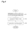
- the processing flow for generating the travel plan and the control width by the ECU 10 will be described in detail with reference to a flowchart in FIG. 4 .
- the ECU 10 repeatedly executes the processing of generating the following travel plan and the control width in the predetermined planned travel period set in advance.
- the vehicle state determination unit 12 determines the vehicle state of the vehicle V.
- the surroundings information determination unit 11 determines the surroundings information of the vehicle V (S11).
- the travel plan generation unit 13 generates the travel plan along the target route set in advance based on at least the surroundings information of the vehicle V and the map information in the map database 4 (S 12).
- the travel plan generation unit 13 generates the control width based on at least any of the surroundings information of the vehicle V determined by the surroundings information determination unit 11 and the vehicle state determined by the vehicle state determination unit 12 (S 13).
- the travel plan generation unit 13 outputs the generated target travel plan and the control width to the travel control unit 15.
- This processing starts when the behavior determination unit 14 determines that the behavior of the vehicle V opposite to the first behavior change is performed within the predetermined control time from the current time. In addition, the travelling state of the vehicle V is assumed to be within the control width of the travel plan.
- the travel control unit 15 may calculate the control values such that the vehicle state becomes gradually close to the target vehicle state, and more gradually than in the case where the vehicle state is outside the control width. Accordingly, in a case where the travelling state of the vehicle V is outside the control width of the travel plan, the travel control unit 15, as described above, for example, may calculate the control values such that the vehicle state becomes closer to the target vehicle state at an earlier stage compared to the case where the current vehicle state is a vehicle state corresponding to the control width.
- the travel control unit 15 calculates the control values such that the vehicle is brought into a restricted vehicle state. Then, the travel control unit 15 outputs the calculated control values to the actuator 6. As described above, the travel control unit 15 controls the travelling of the vehicle V such that the vehicle is brought into a restricted vehicle state (S21).
- the travel control unit 15 determines whether or not to end the process of calculating control values such that the vehicle is brought into a restricted vehicle state (S22). Specifically, the condition for ending the process such as in the first example or the second example described above is set in the travel control unit 15 in advance. The travel control unit 15 determines whether or not the stopping condition set in advance is satisfied. In a case where the ending condition set in advance is satisfied (YES in S22), the travel control unit 15 ends the process of calculating control values such that the vehicle is brought into a restricted vehicle state (S23). Then, the travel control unit 15, as described above, for example, may calculate the control values such that the vehicle V be brought gently close to the target vehicle state.
- the travel control unit 15 performs the process of calculating the control values such that the vehicle be brought into a restricted vehicle state (S21).
- the vehicle autonomous driving system 100 in the present embodiment calculates the control values such that the vehicle is brought into the restricted vehicle state.
- the restricted vehicle state is a vehicle state which corresponds to a control value within the control width, and into which the vehicle is placed by a behavior change (the first restricted behavior change) smaller than the first behavior change.
- a restricted travel plan can be elected, wherein the first restricted behavior change is smaller than the first behavior change, i.e. the behavior change in the case where the vehicle V is controlled to follow the target control values of the target travel plan. Therefore, it is possible to improve the riding comfort in the vehicle V.
- the travel plan generation unit 13 generates the target travel plan until the predetermined control time from the current time, and the behavior determination unit 14 determines whether or not said opposite behavior of the vehicle is to be performed within the travel plan before the predetermined control time. In this case, the behavior determination unit 14 can determine whether or not the behavior of the vehicle is performed opposite to the behavior change within the predetermined control time using the target travel plan for the predetermined control time generated by the travel plan generation unit 13.
- the travel control unit 15 may calculate the control values such that the vehicle is brought into a restricted vehicle state until the vehicle V reaches the timing in the travel plan at which the opposite behavior change is performed. In this way, the vehicle autonomous driving system 100 can stop calculating the control values, which are an exceptional restricted vehicle state, at an appropriate timing, and thus, it is possible to calculate the control values such that thereafter the vehicle is brought again into the target vehicle state.
- the travel control unit 15 may calculate the control values such that the vehicle is brought into a restricted vehicle state until the vehicle state coincides with the target vehicle state after the vehicle V reaches the timing in the travel plan at which the opposite behavior change is performed. In this way, the vehicle autonomous driving system 100 can stop calculating control values which bring the vehicle into the exceptional restricted vehicle state at an appropriate timing. Furthermore, it is possible to calculate the control values such that thereafter the vehicle is brought into the target vehicle state again.
- the travel plan generation unit 13 generates the control width based on at least any of the vehicle state and the surroundings information.
- the vehicle autonomous driving system 100 can perform the generation of, not a constant value, but an appropriate control width considering at least any of the vehicle state and the surroundings information.
- FIG. 6 is a block diagram illustrating a configuration of a vehicle autonomous driving system 100A in the second embodiment.
- the vehicle autonomous driving system 100A includes the external sensor 1, the GPS receiver 2, the internal sensor 3, the map database 4, the navigation system 5, the actuator 6, the ECU 10A and the HMI 7.
- the ECU 10A functionally includes the surroundings information determination unit 11, the vehicle state determination unit 12, the travel plan generation unit 13, a behavior determination unit 14A, a travel control unit (calculation unit) 15A, and a stop detection unit 16.
- the stop detection unit 16 acquires, for example, the target route calculated by the navigation system 5.
- the stop detection unit 16 detects whether or not there is a stop position within a predetermined distance from the vehicle V on the acquired target route.
- the target route information regarding a path longer than a length of a path included in the target route is included.
- the "predetermined distance" in detecting whether or not there is a stop position within a predetermined distance from the vehicle V is a distance longer than the length of the path included in the travel plan. That is, the stop detection unit 16 detects a stop position even if it is not considered in the travel plan at the current time point and which is farther than the range of the travel plan.
- a red signal of a traffic signal (a traffic signal indicating a stop), a stop sign, a crosswalk on which a pedestrian is walking, and the like are stop positions.
- the stop detection unit 16 may detect the stop position by performing image processing based on the imaging information of the camera.
- information of the stop position for example, a stop line
- the stop detection unit 16 may detect the stop position based on the map information.
- the stop detection unit 16 may detect the traffic signal D which is estimated to be a red signal as a stop position. In this case, the stop detection unit 16 may determine whether or not the traffic signal D is the red signal when the vehicle V arrives at the position of the traffic signal D based on a display pattern of the traffic signal D positioned at a predetermined distance from the vehicle V, the speed of the vehicle V, and the distance from the vehicle V to the traffic signal D. As the position of the traffic signal D, the stop detection unit 16 may detect a position directly below the traffic signal D or a position of the stop line E of the traffic signal D.
- the stop detection unit 16 determines whether or not the traffic signal D is the red signal when the vehicle V arrives at the position of the traffic signal D which is currently the red signal.
- the stop detection unit 16 detects an elapsed time for switching the traffic signal D from a green signal to the red signal as the display pattern.
- the stop detection unit 16 may detect the elapsed time for switching the traffic signal D from the green signal to the red signal based on a change of the signal color detected by performing image processing based on imaging information of the camera.
- a time for switching the traffic signal D from the red signal to the green signal is stored in the stop detection unit 16 in advance. This switching time may be a general switching time in the traffic signal D.
- the stop detection unit 16 estimates a remaining time t1 for the traffic signal D to be switched to the green signal based on a timing of switching and the time for switching the traffic signal D from the red signal to the green signal.
- the stop detection unit 16 calculates an arrival time t2 at which the vehicle V will arrive at the position of the traffic signal D.
- the arrival time t2 may be calculated based on the distance from the vehicle V to the traffic signal D and the speed of the vehicle V.
- the stop detection unit 16 may detect the distance from the vehicle V to the traffic signal D by performing image processing based on the imaging information of the stereo camera.
- the stop detection unit 16 may use the current speed of the vehicle V as the speed of the vehicle V.
- the stop detection unit 16 may use a speed based on the target speed included in the target speed included in the as the speed of the vehicle V.
- the stop detection unit 16 detects the traffic signal D as the stop position.
- the behavior determination unit 14A determines whether or not the behavior of the vehicle V opposite to the first behavior change is performed within the predetermined control time from the current time.
- the behavior determination unit 14A in the present embodiment determines whether or not the behavior of the vehicle V opposite to the first behavior change is performed within the predetermined control time from the current time based on the travel plan and the result of detection by the stop detection unit 16. Specifically, firstly, the behavior determination unit 14A determines whether or not the vehicle is in the acceleration state and the deceleration state based on the target speed of the vehicle V included in the travel plan for the planned travel time generated by the travel plan generation unit 13. Next, the behavior determination unit 14A acquires the result of detecting the stop position by the stop detection unit 16.
- the behavior determination unit 14A determines that the behavior of the vehicle V opposite to the first behavior change is to be performed within the predetermined control time from the current time.
- the "predetermined control time" in determining whether or not the behavior of the vehicle V opposite to the first behavior change is performed within the predetermined control time from the current time is a time for the vehicle V to arrive at the position separated by the above-described predetermined distance on the target route from the current position.
- the behavior determination unit 14A determines the acceleration and deceleration behavior based on the travel plan as an opposite behavior of the vehicle V opposite to the first behavior change. In addition, the behavior determination unit 14A determines whether or not the behavior of the vehicle V opposite to the first behavior change is performed within the predetermined control time from the current time for each generation of the travel plan by the travel plan generation unit 13.
- the travel control unit 15A automatically controls the travelling of the vehicle V based on the travel plan and the control width generated from the travel plan generation unit 13 and the result of detection by the behavior determination unit 14A. That is, in a case where the behavior determination unit 14A determines that the vehicle V is in the acceleration state within the planned travel time and is not changed to be in the deceleration state, and in a case where the stop position is detected by the stop detection unit 16, the travel control unit 15A calculates the control values relating to the speed of the vehicle V such that the vehicle is brought into a restricted vehicle state corresponding to the control width.
- the travel control unit 15A calculates control values such that the vehicle be brought into a restricted vehicle state, wherein it remains until a new travel plan is generated by the travel plan generation unit 13, which includes the change of the state of the vehicle V to the deceleration state.
- the travel control unit 15A ends the control values calculation process based on the first example or the second example of the ending condition set in advance in the travel control unit 15A.
- the stop detection unit 16 estimates the remaining time t1 for the traffic signal D to be switched to the green signal (S31).
- the stop detection unit 16 calculates the arrival time t2 for the vehicle V to arrive at the position of the traffic signal D (S32).
- the stop detection unit 16 determines whether or not the remaining time t1 for the traffic signal D to be switched to the green signal is equal to or longer than the arrival time t2 for the vehicle V to arrive at the position of the traffic signal D (S33).
- the stop detection unit 16 determines that the traffic signal D is the stop position (S34). On the other hand, in a case where the remaining time t1 is not equal to or longer than the arrival time t2 (NO in S33), the stop detection unit 16 does not determine that the traffic signal D is the stop position (S35).
- the travel control unit 15A may calculate the control values such that the vehicle state becomes close to the target vehicle state at an earlier stage compared to the case where the current vehicle state is a vehicle state corresponding to the control width.
- the behavior determination unit 14A determines whether or not the behavior that makes the vehicle V be in the acceleration state is included in the travel plan based on the target speed of the vehicle V included in the travel plan generated by the travel plan generation unit 13 (S41). In a case where the behavior that makes the vehicle V be in the acceleration state is not included in the travel plan (NO in S41), the travel control unit 15A does not calculate control values so as to bring the vehicle in a restricted vehicle state. In this case, for example, the travel control unit 15A may simply calculate control values such that the vehicle is gently brought close to the target vehicle state.
- the behavior determination unit 14A determines whether or not the behavior that makes the vehicle V be in the deceleration state is included in the travel plan based on the target speed of the vehicle V included in the travel plan generated by the travel plan generation unit 13 (S42). In the processing in S42, the case where it is determined that the behavior causing the deceleration state to be included in the travel plan is the case where the behavior determination unit 14A determines that the vehicle V has acceleration and deceleration behaviors.
- the travel control unit 15A calculates control values causing the speed (which is the vehicle state) of the vehicle V to be limited to a restricted vehicle state. Then, the travel control unit 15A outputs the calculated control values to the actuator 6. As described above, the travel control unit 15A controls the travelling of the vehicle V such that the speed of the vehicle V becomes the restricted vehicle state (S43).
- the travel control unit 15A determines whether or not to end the process of calculating control values such that the speed of the vehicle V becomes the restricted vehicle state (S44). Specifically, as in the first example or the second example described above, the condition for ending the control values calculation process is set in advance in the travel control unit 15A. The travel control unit 15A determines whether or not the ending condition set in advance is satisfied. In a case where the ending condition set in advance is satisfied (YES in S44), the travel control unit 15A ends the process of calculating the control values such that the speed of the vehicle V becomes the restricted vehicle state (S45). Then, for example, as described above, the travel control unit 15A may calculate the control values such that the vehicle V is gently brought close to the target vehicle state.
- the travel control unit 15A keeps calculating control values such that the speed of the vehicle V becomes (or remains) the restricted vehicle state (S43). As described above, the travel control unit 15A continues calculating the control values such that the speed of the vehicle V becomes the restricted vehicle state until the ending condition is satisfied.
- the stop detection unit 16 detects whether or not there is a stop position within a predetermined distance from the vehicle V on the target route (S46). In a case where the stop position is detected (YES in S46), the travel control unit 15A calculates the control values such that the speed of the vehicle V becomes the restricted vehicle state. Then, the travel control unit 15A outputs the calculated control values to the actuator 6. As described above, the travel control unit 15A controls the travelling of the vehicle V such that the speed of the vehicle V becomes the restricted vehicle state (S47).
- FIG. 10 a processing flow for ending the process of controlling the movement of the vehicle V such that the vehicle V is brought to a restricted vehicle speed calculated by the travel control unit 15A in S47 in FIG. 9 will be described using a flowchart in FIG. 10 .
- the processing illustrated in the flowchart in FIG. 10 starts when the processing S47 in FIG 9 starts.
- the travel control unit 15A determines whether or not a new travel plan has been generated by the travel plan generation unit 13 (S51). In a case where a new travel plan has not been generated (NO in S51), the travel control unit 15A performs the processing S51 again.
- the travel control unit 15A determines whether or not the newly generated travel plan is a travel plan that includes a change of the vehicle state of the vehicle V to the deceleration state (S52).
- the travel control unit 15A performs the process of S51 again.
- the travel control unit 15A ends the process (process S47 in FIG. 9 ) of controlling the movement of the vehicle V such that the vehicle V is brought to a restricted speed (as a restricted vehicle state).
- the process S47 in FIG. 9 also ends in a case where the change of the state of the vehicle V to the acceleration state is not included in the travel plan newly generated by the travel plan generation unit 13 (NO in S41).
- the process performed in S47 also ends in a case where the stop position is not detected by the stop detection unit 16 (NO in S46) when the new travel plan is generated by the travel plan generation unit 13.
- the travel control unit 15A in the present embodiment calculates the control values relating to the speed of the vehicle such that the vehicle be brought to a restricted speed corresponding to the control width.
- the vehicle autonomous driving system 100A calculates the control values relating to the speed of the vehicle V such that the vehicle V be brought to the restricted vehicle speed.
- the behavior change can be smaller compared to the case where the travelling of the vehicle V is controlled to follow the target control value in the travel plan. Therefore, it is possible to improve the riding comfort in the vehicle V.
- the stop detection unit 16 determines whether or not the traffic signal D is the red signal when the vehicle V arrives at the position of the traffic signal D based on the display pattern or the like of the traffic signal D positioned at a predetermined distance from the vehicle V on the target route. In this way, the stop detection unit 16 can detect the stop position while considering the timing of changing the signal indicated by the traffic signal D.
- the travel control unit 15A calculates the control values such that the vehicle is brought into a restricted vehicle state until the travel plan that includes the change of the state of the vehicle V to the deceleration state is newly generated by the travel plan generation unit 13. In this way, the vehicle autonomous driving system 100A can stop calculating control values causing the vehicle to reach an exceptional restricted vehicle state at an appropriate timing. It is further possible to calculate the control values such that thereafter the vehicle is brought into the target vehicle state again.
- control width is not limited to being generated based on at least any of the surroundings information of the vehicle V and the vehicle state.
- the control width may be generated based on information other than the surroundings information of the vehicle V and the vehicle state.
- the control width may be a constant value determined in advance.
- the calculation of the control values such that the vehicle is brought into a restricted vehicle state may stop according to an ending condition other than the ending conditions described above.
Abstract
Description
- The present invention relates to an vehicle autonomous driving system.
- For example, as disclosed in
US Patent Application Publication No. 2010/0228420 , a vehicle autonomous driving system that controls a travelling of a vehicle is disclosed. - The vehicle autonomous driving system like this generates a travel plan including a trajectory on which the vehicle travels based on a positional relationship between the host vehicle and one or more vehicle(s) surrounding the host vehicle, and controls the travelling of the vehicle based on the generated travel plan.
- Incidentally, there is a case where the vehicle autonomous driving system controls the behavior or motion of the host vehicle such that it changes in a first manner, and then changes in an opposite manner, for instance by causing the host vehicle to decelerate after an acceleration, or causing the host vehicle to turn left after turning right - due to the position of the host vehicle relative to the other vehicle(s) surrounding the host vehicle. In this case, the change of the vehicle behavior is large, because the motion of the host vehicle in changed in the second manner opposite to the first manner; consequently, a riding comfort in the vehicle may be considered to deteriorate. Therefore, it is desirable to suppress the deterioration of riding comfort in the vehicle even in case where the behavior of the host vehicle is changed in a first manner and then a second manner opposite to the first manner.
- Therefore, an object of an aspect of the present invention is to provide a vehicle autonomous driving system in which, in case it is determined that a behavior change of a vehicle (an opposite behavior change) opposite to a previous behavior change (a first behavior change), is performed, a driving comfort of the vehicle can be improved compared with that in a case where the travelling of the vehicle is controlled so as to follow target control values in the travel plan.
- A vehicle autonomous driving system according to an aspect of the present invention includes: a surroundings information determination unit configured to determine surroundings information concerning surroundings of a vehicle; a travel plan generation unit configured to generate a target travel plan along a pre-set target route based on the surroundings information of the vehicle and generate a control width of target control values of the vehicle constituting the target travel plan; a vehicle state determination unit configured to determine a vehicle state of the vehicle; a calculation unit configured to calculate control values for controlling the vehicle such that the vehicle state becomes a target vehicle state corresponding to the target control values based on the target travel plan, the control width, and the vehicle state; an actuator configured to control the vehicle based on the control values; and a behavior determination unit configured to determine whether or not an opposite behavior change of the vehicle which is opposite to a first behavior change of the vehicle is to be performed according to the target travel plan. In addition, the calculation unit is configured to calculate the control value such that, in a case where it is determined by the behavior determination unit that the opposite behavior change is to be performed, the vehicle follows a restricted travel plan wherein:
- the vehicle follows the target travel plan until a first restricted behavior change, which is smaller than the first behavior change;
- after the first restricted behavior change and until an opposite restricted behavior change, the vehicle is brought into a restricted state which corresponds to a control value within the control width; and
- after the opposite restricted behavior change, the vehicle follows the target travel plan.
- In a case where it is determined by the behavior determination unit that the opposite behavior change is to be performed (for instance, a case where the vehicle behavior changes from an acceleration to a deceleration or the like), the vehicle autonomous driving system calculates the control value such that the vehicle is brought into a restricted vehicle state. The restricted vehicle state is a vehicle state which corresponds to a control value within the control width, and into which the vehicle is placed by a behavior change (the first restricted behavior change) smaller than the first behavior change. In this way, in the vehicle autonomous driving system, in a case where it is determined that the target travel plan of the vehicle includes a first behavior change and an opposite behavior change opposite to the first behavior change, a restricted travel plan can be elected, wherein the first restricted behavior change is smaller than the first behavior change, i.e. the behavior change in the case where the vehicle is controlled to follow the target control values of the target travel plan. Therefore, it is possible to improve the riding comfort in the vehicle.
- The travel plan generation unit may be configured to generate the target travel plan until a predetermined control time from the current time, and the behavior determination unit may be configured to determine that said opposite behavior change is to be performed in the travel plan only if it is performed before the predetermined control time. In this case, the behavior determination unit can determine whether or not the opposite behavior change is performed within the predetermined control time using the target travel plan generated by the travel plan generation unit until the predetermined control time.
- The calculation unit may be configured to calculate the control values such that, in a case where it is determined by the behavior determination unit that the opposite behavior change is to be performed, the vehicle remains in the restricted vehicle state until the vehicle reaches a timing in the travel plan at which the opposite behavior change according to the target travel plan is performed. In this way, the vehicle autonomous driving system can stop calculating control values, which are an exceptional restricted vehicle state, at an appropriate timing. In addition, it is possible to calculate control values such that thereafter the vehicle is brought into the target vehicle state again.
- The calculation unit may be configured to calculate the control values such that, in a case where it is determined by the behavior determination unit that the opposite behavior change is to be performed, the vehicle remains in the restricted vehicle state until the vehicle state coincides with the target vehicle state after the vehicle has reached the timing in the travel plan at which the opposite behavior change according to the target travel plan is performed. In this way, the vehicle autonomous driving system can stop calculating of the control value which is an exceptional restricted vehicle state at an appropriate timing. In addition, it is possible to calculate the control values such that thereafter the vehicle is brought into the target vehicle state again.
- The vehicle autonomous driving system further includes a stop detection unit configured to detect whether or not there is a stop position on the target route of the vehicle within a predetermined distance from the vehicle. The travel plan generation unit may be configured to generate the target travel plan for a planned travel time shorter than the predetermined control time, the behavior determination unit may be configured to determine whether or not the vehicle is in an acceleration state or a deceleration state based on the target travel plan, and in a case where it is determined that the vehicle is in the acceleration state and is not in the deceleration state within the planned travel time and in a case where the stop position is detected by the stop detection unit as being within said predetermined distance from the vehicle, the behavior determination unit is configured to determine that the opposite behavior change is to be performed. In a preferred embodiment, as above, even though an opposite behavior which is opposite to the first behavior change cannot be identified in the target travel plan within the planned travel time, the vehicle autonomous driving system can calculate control values relating to the speed of the vehicle such that the speed of the vehicle correspond to the restricted vehicle state. In this way, in the vehicle autonomous driving system, it is possible to apply to the vehicle a first restricted behavior change smaller than the first behavior change which corresponds to the case where the vehicle is controlled based on the target control values of the target travel plan. Therefore, it is possible to improve the riding comfort in the vehicle.
- The stop detection unit may be configured to determine whether or not a traffic signal will be a red signal when the vehicle arrives at a position of the traffic signal based on the display pattern of the traffic signal positioned within the predetermined distance from the vehicle on the target route, the speed of the vehicle, and the distance from the vehicle to the traffic signal, and the stop detection unit is configured, in a case where it is determined that the traffic signal will be the red signal when the vehicle (V) arrives at the position of the traffic signal, to determine that there is a stop position within the predetermined distance. In this case, the stop detection unit can detect the stop position while considering the timing of the signal change indicated by the traffic signal.
- The calculation unit may be configured to calculate the control value such that, in a case where it is determined by the behavior determination unit that the opposite behavior change is performed, the vehicle remains in the restricted vehicle state until the travel plan that includes the change of the vehicle state to the deceleration state is newly generated by the travel plan generation unit. In this way, the vehicle autonomous driving system can stop calculating control values, which are an exceptional restricted vehicle state, at an appropriate timing. In addition, it is possible to calculate the control values such that thereafter the vehicle is brought into the target vehicle state again.
- The travel plan generation unit may be configured to generate the control width based on at least any of the vehicle state and the surroundings information. In this case, the vehicle autonomous driving system can perform the generation of an appropriate control width considering any of the vehicle state and the surroundings information rather than a constant value.
- The control width generated by the travel plan generation unit is a width, or a range of deviation values or the like, of the target control values, which defines the deviations of the control values relative to the target vehicle state as defined by the travel plan that are considered as acceptable.
- According to an aspect of the present invention, in a case where it is determined that the opposite behavior of the vehicle is to be performed, it is possible to improve the riding comfort in the vehicle compared to the case where the travelling of the vehicle is controlled to follow the target control values based on the target travel plan.
-
-
FIG. 1 is a block diagram illustrating a configuration of a vehicle autonomous driving system in a first embodiment. -
FIG. 2 is a plan view for explaining a setting of a target position and a control width of the target position. -
FIG. 3 is a diagram for explaining a setting of a target speed and a control width of the target speed. -
FIG. 4 is a flowchart illustrating a processing flow of generating the travel plan and the control width. -
FIG. 5 is flowchart illustrating a processing flow of controlling a travelling of the vehicle such that a vehicle state becomes a restricted vehicle state. -
FIG. 6 is a block diagram illustrating a configuration of a vehicle autonomous driving system in a second embodiment. -
FIG. 7 is a plan view illustrating a positional relationship between a traffic signal and a vehicle. -
FIG. 8 is a flowchart illustrating a processing flow of estimating a red light of the traffic signal as a stop position. -
FIG. 9 is a flowchart illustrating a processing flow of controlling the travelling of the vehicle such that the vehicle is brought into a restricted vehicle state. -
FIG. 10 is a flowchart illustrating a processing flow of stopping the process of controlling the travelling of the vehicle such that the vehicle is brought into a restricted vehicle state. - Hereinafter, embodiments of the present invention will be described in detail with reference to the drawings. In the description, the same reference signs will be given to the same or corresponding elements, and the description thereof will not be repeated.
-
FIG. 1 is a block diagram illustrating a configuration of a vehicleautonomous driving system 100 in a first embodiment. As illustrated inFIG. 1 , a vehicleautonomous driving system 100 is mounted on a vehicle V such as a passenger car or the like. The vehicleautonomous driving system 100 includes anexternal sensor 1, a global positioning system (GPS)receiver 2, an internal sensor 3, amap database 4, anavigation system 5, anactuator 6, an electronic control unit (ECU) 10 and a human machine interface (HMI) 7. - The
external sensor 1 is a detection device configured to detect information on the surroundings of the vehicle V. Theexternal sensor 1 includes at least one of a camera, radar, and laser imaging detection and ranging (LIDAR). - The camera is an imaging device for imaging surroundings of the vehicle V. The camera is, for example, provided on the inside of windshield of the vehicle V. The camera transmits the imaging information to the
ECU 10. The camera may be a monocular camera or may be a stereo camera. The stereo camera includes two imaging units that are arranged so as to reproduce a binocular parallax. The imaging information of the stereo camera also includes information on the depth direction. - The radar detects an obstacle outside of the vehicle V using a radio wave (for example, a millimeter wave). The radar detects the obstacle by transmitting the radio wave to the surroundings of the vehicle V and receiving the wave reflected from the obstacle. The radar transmits the detected obstacle information to the
ECU 10. - The LIDAR detects the obstacle outside the vehicle V using light. The LIDAR transmits the light to the surroundings of the vehicle V, measures the distance to the reflection point by receiving the light reflected from the obstacle, and then, detects the obstacle. The LIDAR transmits the detected obstacle information to the
ECU 10. The camera, the LIDAR, and the radar are not necessarily provided in an overlapping manner. - The
GPS receiver 2 measures a position (for example, the latitude and the longitude of the vehicle V) of the vehicle V by receiving signals from three or more GPS satellites. TheGPS receiver 2 transmits the measured position information of the vehicle V to theECU 10. Instead of theGPS receiver 2, another means for specifying the latitude and the longitude at which the vehicle V is present may be used. In addition, in order to match the measuring result by the sensor with map information described below, it is preferable that the function of measuring the orientation of the vehicle V be also provided. - The internal sensor 3 is a detection device configured to detect a travelling state of the vehicle V. The internal sensor 3 includes at least one of a vehicle speed sensor, an acceleration sensor, and a yaw rate sensor. It is not essential for the internal sensor 3 to include the vehicle speed sensor, the acceleration sensor, or the yaw rate sensor. The vehicle speed sensor is a detection device configured to detect the speed of the vehicle V. As the vehicle speed sensor, for example, a wheel speed sensor is used, which is provided on vehicle wheels of the vehicle V or a drive shaft and the like rotating integrally with vehicle wheels and detects a rotational speed of the vehicle wheels. The vehicle speed sensor transmits the detected vehicle speed information (vehicle wheel speed information) to the
ECU 10. - The acceleration sensor is a detection device configured to detect an acceleration (acceleration and deceleration) of the vehicle V. The acceleration sensor includes, for example, a longitudinal acceleration sensor that detects acceleration in the longitudinal direction of the vehicle V and a lateral acceleration sensor that detects a lateral acceleration of the vehicle V. The acceleration sensor transmits acceleration information of the vehicle V to the
ECU 10. The yaw rate sensor is a detection device of the vehicle V configured to detect a yaw around the vertical axis of the center of gravity of the vehicle V (rotational angular velocity). As the yaw rate sensor, for example, a gyro sensor can be used. The yaw rate sensor transmits the detected yaw rate information of the vehicle V to theECU 10. - The
map database 4 is a database in which map information is included. The map database is formed, for example, in a hard disk drive (HDD) mounted on the vehicle V. In the map information, for example, position information of roads, information on road types (a type of a curve or a straight portion and a curvature of the curve), and position information of intersections, and branch points are included. Furthermore, in order to use position information of a shielding structure such as a building or a wall and simultaneous localization and mapping technology (SLAM), it is preferable for the map information to include an output signal of theexternal sensor 1. The map database may be stored in a computer in a facility such as an information processing center which is capable of communicating with the vehicle V. - The
navigation system 5 is a device configured to perform guidance to a destination set by a driver of the vehicle V for a driver of the host vehicle V. Thenavigation system 5 calculates a travelling route of the host vehicle V based on the position information of the vehicle V measured by theGPS receiver 2 and the map information in themap database 4. The route may, for example, be a specified preferable lane in a multi-lane section. Thenavigation system 5 calculates, for example, a target route from the position of the vehicle V to the destination and performs notification to the driver by displaying the target route on a display or by a voice output from a speaker. Thenavigation system 5, for example, transmits the target route information of the vehicle V to theECU 10. Thenavigation system 5 may be stored in a computer in a facility such as an information processing center which is capable of communicating with the vehicle V. - The
actuator 6 is a device configured to control the vehicle state of the vehicle V. Theactuator 6 includes at least a throttle actuator, a brake actuator, and a steering actuator. The throttle actuator controls a supply amount (throttle opening degree) of air to an engine according to a control value from theECU 10, and controls the driving power of the vehicle V. In a case where the vehicle V is a hybrid vehicle or an electric vehicle, the throttle actuator is not included and the driving power is controlled by the control value from theECU 10 being input to a motor which is a source of the driving force. - The brake actuator controls a brake system according to the control value from the
ECU 10 and controls the braking force given to the wheels of the vehicle V. For example, a hydraulic brake system can be used as the brake actuator. The steering actuator controls the driving of an assist motor that controls a steering torque in the electric power steering system according to the control value from theECU 10. In this way, the steering actuator controls the steering torque of the vehicle V. - The
HMI 7 is an interface configured to perform an input and output of information between the occupants (including the driver) of the vehicle V and the vehicleautonomous driving system 100. TheHMI 7 includes, for example, a display panel for displaying the imaging information for the occupant, a speaker for audio output, and an operation button or a touch panel for the occupant to perform the input operation. When an input operation to start or stop the autonomous travelling is performed by the occupant, theHMI 7 starts or stops the autonomous travelling by outputting the signals to theECU 10. When arriving at the destination where the autonomous driving stops, theHMI 7 notifies the occupants of the arrival at the destination. TheHMI 7 may output information to the occupants using a wirelessly connected mobile information terminal or may receive information inputted by the occupants using the mobile information terminal. - As illustrated in
FIG. 1 , theECU 10 controls the autonomous driving of the host vehicle V. TheECU 10 is an electronic control unit including a central processing unit (CPU), read only memory (ROM), random access memory (RAM), and the like. In theECU 10, various controls are performed by loading the program stored in the ROM into the RAM and executing the program by the CPU. TheECU 10 may be configured with a plurality of electronic control units. - Functionally, the
ECU 10 includes a surroundingsinformation determination unit 11, a vehiclestate determination unit 12, a travelplan generation unit 13, abehavior determination unit 14, and a travel control unit (a calculation unit) 15. - The surroundings
information determination unit 11 determines surroundings information of the vehicle V based on the detection results of the external sensor 1 (for example, the imaging information of the camera, the obstacle information of the radar, or the obstacle information of the LIDAR). The surroundings information includes, for example, a position of a lane line of a travel lane or a position of a center of the lane with respect to the vehicle V or a width of the travel lane, a shape of a road (for example, a curvature of the travel lane, a gradient change in the road surface effective for estimation by theexternal sensor 1, an undulation, or the like), a situation of the obstacles (for example, surrounding vehicles) around the vehicle V (for example, information for distinguishing between a fixed obstacle and a moving obstacle, a position of the obstacle with respect to the vehicle V, a speed of the obstacle, a movement direction of the obstacle with respect to the vehicle V, a relative speed of the obstacle with respect to the vehicle V, and a size of the obstacle). In addition, it is preferable to compensate for the accuracy of the position and the direction of the vehicle V acquired by theGPS receiver 2 by matching the detection result of theexternal sensor 1 with the map information. - The vehicle
state determination unit 12 determines the vehicle state of the vehicle V. The position of the vehicle V (hereinafter, referred to as "vehicle position") and the travelling state of the vehicle V may be included in the vehicle state. - The vehicle
state determination unit 12 determines the vehicle position on the map based on the position information of the vehicle V received from theGPS receiver 2 and the map information in themap database 4. The vehiclestate determination unit 12 may acquire the vehicle position from thenavigation system 5 and determines the vehicle position, which is used in thenavigation system 5. In a case where the vehicle position of the vehicle V can be measured by a sensor installed outside on the road or the like, the vehiclestate determination unit 12 may acquire the vehicle position by a communication with the sensor. - The vehicle
state determination unit 12 determines the travelling state of the vehicle V based on the detection result of the internal sensor 3 (for example, the vehicle speed information from the vehicle sensor, the acceleration information from the acceleration sensor, the yaw rate information from the yaw rate sensor). For example, the speed, acceleration, yaw rate of the vehicle V are included in the travelling state of the vehicle V. - The travel
plan generation unit 13 generates a target trajectory of the vehicle V based on the target route calculated by thenavigation system 5, and information about the obstacles around the vehicle V determined by the surroundings information determination unit 11 (including a vehicle position and direction of any surrounding vehicle). The target trajectory is a trajectory of the host vehicle V on the target route. The travelplan generation unit 13 generates the target travel plan such that the host vehicle V can travel while satisfying standards such as safety, regulatory compliance, and driving efficiency on the target route. Here, it is needless to say that the travelplan generation unit 13 generates the target trajectory of the vehicle V so as to avoid a contact with obstacles based on the situation of the obstacles around the host vehicle V. - The target route described here also includes a travel route generated based on the surroundings information or the map information when a destination is not clearly set by a driver as a travel route along the road in the "driving assistance device" disclosed in
Japanese Patent No. 5382218 WO2011/158347 ) or the "driving assistance device" disclosed inJapanese Unexamined Patent Application Publication No.2011-162132 - The travel
plan generation unit 13 generates the target travel plan according to the generated target trajectory. That is, the travelplan generation unit 13 generates the target travel plan along the target route set based on the surroundings information of the vehicle V and the map information in themap database 4. The travelplan generation unit 13 may generate the target travel plan without using the map information in themap database 4 such as in a case of determining the target trajectory based on the surroundings information of the vehicle V and generating the target travel plan according to the determined target trajectory. The target control value which is a target for controlling the vehicle state of the vehicle V is included in the target travel plan. It is preferable for the travelplan generation unit 13 to generate combinations of two elements of a target position p on a coordinate system fixed on the vehicle V and a target speed v at each target position as the target control value in the target travel plan, that is, a plurality of configuration coordinates (p, v). Here, each target position p has at least information of the x and y coordinates on the coordinate system fixed on the vehicle V or information equivalent thereto. The target control value in the target travel plan is not limited to be represented by the configuration coordinates described above. The target travel plan may use a target time t, for example, instead of the target speed v in the configuration coordinates (p, v) described above. In addition, in a case of using the target time t instead of the target speed v in the configuration coordinates (p, v) described above, the target control value may further include an orientation of the vehicle V at the time point of the target time t. - Furthermore, a curve connecting the configuration coordinates may be approximated by a spline function or the like, and then, the parameters of the curve may be used as the travel plan. Any arbitrary known method can be used for the generation of the travel plan as long as the behavior of the vehicle V can be indicated.
- The travel plan may further include a curvature of the target trajectory of the vehicle V at each target position, a target yaw angle of the vehicle V at each target position, and a target acceleration of the vehicle V at each target position as the target control value, in addition to the plurality of target positions through which the vehicle V passes along the target trajectory and the target speed at each target position.
- In the present embodiment, the travel
plan generation unit 13 generates the target travel plan for a predetermined period called planned travel time (for example, several tens of seconds) from the current time. In addition, the planned travel time is a time set in advance. In addition, the travelplan generation unit 13 sequentially generates the target travel plan in a predetermined generation cycle set in advance. In each cycle, the travelplan generation unit 13 may generate the entire target travel plan from the current position to the destination, or may generate a target travel plan only for the planned travel time. - The travel plan may be data that indicates trends of the target speed of the vehicle V, the target acceleration or deceleration, and a target steering torque when the vehicle V is travelling the target trajectory along the target route. The travel plan may include a pattern of the target speed of the vehicle V, a pattern of the target acceleration or deceleration, and a pattern of the target steering torque. Here, the travel
plan generation unit 13 may generate the travel plan such that the travel time (a time required for the vehicle V to arrive at the destination) becomes shortest. - Incidentally, for example, the pattern of the target speed can be data comprising a target vehicle speed set in association with the time for each target control position with respect to the target control position set on the target trajectory in a predetermined interval (for example, one meter). The pattern of the target acceleration or deceleration can be, for example, data comprising the target acceleration or deceleration set in association with the time for each target control position with respect to the target control position set on the target trajectory in a predetermined interval (for example, one meter). The pattern of the target steering can be, for example, data formed from the target steering set in association with the time for each target control position with respect to the target control position set on the target trajectory in a predetermined interval (for example, one meter).
- The travel
plan generation unit 13 further generates the control width of the target control value of the vehicle V in the travel plan in addition to the travel plan. The travelplan generation unit 13 generates the control width based on at least any surroundings information of the vehicle V determined by the surroundingsinformation determination unit 11 and the vehicle state determined by the vehiclestate determination unit 12. Preferably, the control width is respectively set for each target control value in the travel plan. However, the travelplan generation unit 13 may not generate a control width corresponding to all types of the target control value in the travel plan. For example, in a case where the target position and the target speed are set as the target control values, the travelplan generation unit 13 may generate a control width with respect to only the target position. The travelplan generation unit 13 sequentially generates control width in a predetermined generation cycle set in advance, preferably together with the target travel plan. - In addition, a dimension (unit) of the control width is the same as that of the target control value of the vehicle V in the travel plan. That is, for example, the control width of the target position in a case where the target position is included in the target control value is the width of the position. For example, the control width of the target speed in a case where the target speed is included in the target control value is the width of the speed.
- The control width generated by the travel
plan generation unit 13 is a width of the target control value allowable in terms of the travel plan even if the vehicle state deviates from the target vehicle state. For example, the travelplan generation unit 13 may generate the control width while considering the riding comfort and the degree of safety of the vehicle. The generation of the control width while considering the riding comfort in the vehicle may be the generation of the width of target control value in which the vehicle V can be caused to travel in such a manner that the lateral acceleration occurring in the vehicle V becomes equal to lower than a predetermined reference value set in advance. The generation of the control width while considering the safety of the vehicle may be the generation of the width of target control value in which the vehicle V can be caused to travel in such a manner that a vehicle-to-vehicle distance from the vehicle V to a surrounding vehicle becomes equal to or longer than a predetermined reference value set in advance. - Here, a specific example of the travel plan and the control width will be described.
FIG. 2 is a plan view for explaining the setting of the target position and the control width of the target position in a case where the target position is included in the target control value in the travel plan. R illustrated inFIG. 2 is a travel lane on which the vehicle V travels. L1 and L2 illustrated in solid lines are lane lines which are boundaries between the travel lane R and adjacent lanes. T1 illustrated by a dashed line is a target trajectory connecting a plurality of target positions in the travel plan. W1 is a control width of the target position. The control width W1 is the direction normal to the target trajectory T1 and can be represented as a length between a control width boundary line Wa1 and a control width boundary line Wb1. The control width boundary line Wa1 illustrated by a dotted line is a curved line connecting the maximum values on the left side of the vehicle V in the control width generated for each target position. The control width boundary line Wb1 illustrated by a dotted line is a curved line connecting the maximum values on the right side of the vehicle V in the control width generated for each target position. InFIG. 2 , the control width W is a constant, but the control width W may not be a constant. -
FIG. 3 is a diagram for explaining the setting of the target speed and the control width of the target speed in a case where the target speed is included in the target control value in the travel plan. InFIG. 3 , examples of the temporal changes of the target speed in the target control value and the temporal changes of the control width of the target speed are illustrated. T2 illustrated by a dashed line represents the temporal change of the target speed in the target control value. W2 illustrated by a dotted line represents a control width boundary line indicating the upper limit of the control width of the target speed. Wb2 illustrated by a dotted line represents a control width boundary line indicating the lower limit of the control width of the target speed. W2 is the control width of the target speed. The control width W2 can be represented as the speed between the control width boundary line Wa2 which is the upper limit of the control width and the control width boundary line Wb2 which is the lower limit of the control width. - Next, an example of setting the control width generated by the travel
plan generation unit 13 will be described. For example, the travelplan generation unit 13 may generate the control width based on the width of the travel lane of the vehicle V which is the surroundings information. In this case, if the width of the travel lane is wide, the travelplan generation unit 13 may make the control width be wider than that in a case where the width of the travel lane is narrow. The travelplan generation unit 13 may determine the width of the travel lane by, for example, acquiring it from the surroundingsinformation determination unit 11. The travelplan generation unit 13 may generate the control width based on surroundings information other than the width of the travel lane. - The travel
plan generation unit 13 may generate the control width based on, for example, the travelling state included in the vehicle state of the vehicle V. In this case, if the speed of the vehicle V which is the travelling state is high, the travelplan generation unit 13 may make the control width be narrower than that in a case where the speed of the vehicle V is low. The travelplan generation unit 13 may determine the speed of the vehicle V, for example, by acquiring it from the vehiclestate determination unit 12. If the yaw rate of the vehicle V which is the travelling state is large, the travelplan generation unit 13 may make the control width be narrower than that in a case where the yaw rate of the vehicle V is small. In this case, the travelplan generation unit 13 may determine the yaw rate by acquiring it from the vehiclestate determination unit 12. If the longitudinal acceleration or the lateral acceleration of the vehicle V which is the travelling state is large, the travelplan generation unit 13 may make the control width be narrower than that in a case where the longitudinal acceleration or the lateral acceleration of the vehicle V is small. In this case, the travelplan generation unit 13 may determine the longitudinal acceleration or the lateral acceleration by acquiring it from the vehiclestate determination unit 12. - The
behavior determination unit 14 determines whether or not a behavior change opposite to a first behavior change is to be performed within a predetermined control time from the current time, according to the target travel plan. In the present embodiment, thebehavior determination unit 14 determines whether or not the vehicle V undergoes a behavior change opposite to a first behavior change of the vehicle V based on the behavior of the vehicle V included in the target travel plan generated by the travelplan generation unit 13. In the present embodiment, the "predetermined control time" used for determining whether or not a behavior change opposite to a previous behavior change is to be performed within said predetermined control time from the current time is equal to the planned travel time used when the travelplan generation unit 13 generates the travel plan, but it can also be shorter than the planned travel time. In this way, thebehavior determination unit 14 can determine whether or not a behavior change opposite to the first behavior change is performed based on the target travel plan. - The
behavior determination unit 14 determines whether or not a behavior change of the vehicle V opposite to the first behavior change is performed within the predetermined control time from the current time within the target travel plan for each generation of the travel plan by the travelplan generation unit 13. The predetermined control time in the present embodiment may be a predetermined time set in advance. - Specifically, as the opposite behavior change of the vehicle V opposite to the first behavior change, the
behavior determination unit 14 may determine the change from an acceleration to a deceleration behavior or vice-versa, in which the acceleration/deceleration state is opposite to that of the first behavior, or a change of a steering behavior in which the steering direction of the vehicle V becomes opposite to that of the first behavior. The acceleration and deceleration behavior is the behavior of the vehicle V changing from the acceleration state to the deceleration state or the behavior of the vehicle V changing from the deceleration state to the acceleration state. Thebehavior determination unit 14 may determine the acceleration and deceleration behavior based on the target speed at each target position included in the travel plan. The steering behavior is the behavior of the vehicle V changing from the right steering angle state in which the vehicle V turns to the right (i.e., the vehicle moves in a direction on the right of the current direction of the vehicle), to the left steering angle state in which the vehicle V turns to the left (i.e. moves in a direction on the left of the current direction of the vehicle), or the behavior of the vehicle V changing from the left steering angle state in which the vehicle V turns to the left to the right steering angle state in which the vehicle V turns to the right. Thebehavior determination unit 14 may determine whether the vehicle V is in the right steering angle state or in the left steering angle state based on the change of the target trajectory (the turning direction of the target trajectory or the like). - When determining the acceleration/deceleration behavior, also if some travelling at a constant speed takes place in the time from the acceleration state to the deceleration state or in the time from the deceleration state to the acceleration state, the
behavior determination unit 14 may determine that the behavior of the vehicle includes an acceleration and a deceleration behavior, in which the acceleration/deceleration state at a second time is opposite to the acceleration/deceleration state at a first time. In addition, when determining the steering angle behavior, also in a case where straight travelling (the state in which the steering angle is zero) takes place in the time from the right steering angle state to the left steering angle state, or vice-versa, thebehavior determination unit 14 may determine that the behavior of the vehicle includes an opposite steering angle behavior in which the steering angle direction is opposite to the steering angle direction during a previous period corresponding or defining a first steering angle behavior. - Most of the time, the
travel control unit 15 automatically controls the travelling of the vehicle V based on the target travel plan and the control width generated by the travelplan generation unit 13. Specifically, thetravel control unit 15 calculates the control values such that the vehicle state of the vehicle V becomes the target vehicle state corresponding to the target control values of the target travel plan based on the target travel plan and the control width generated by the travelplan generation unit 13 and the vehicle state determined by the vehiclestate determination unit 12. Thetravel control unit 15 outputs the calculated control values to theactuator 6. In this way, thetravel control unit 15 controls the travelling of the vehicle V such that the vehicle V autonomously travels according to the target travel plan. The target vehicle state corresponding to the target control values is the target vehicle state of the vehicle V realized by the output of theactuator 6 according to the target control values in the travel plan. - However, if the current vehicle state is not the target vehicle state corresponding to the target control values in the travel plan, the
travel control unit 15 causes the vehicle state to be closer to the target vehicle state. In particular, thetravel control unit 15 may control the travelling of the vehicle V based on whether or not the current vehicle state determined by the vehiclestate determination unit 12 is a state within the control width of the target control values. For example, if the current state of the vehicle is a state within the control width of the target control values, thetravel control unit 15 may calculate the control values such that the vehicle state becomes gradually closer to the target vehicle state, in particular more gradually than in a case where the current vehicle state is outside the control width of the target control values. - In addition, if the
behavior determination unit 14 determines that the vehicle V is to execute a behavior change opposite to a first behavior change within the predetermined control time from the current time, thetravel control unit 15 calculates the control values such that the vehicle is brought into a restricted vehicle state. The restricted vehicle state is a vehicle state which corresponds to a control value within the control width, and into which the vehicle is placed by a behavior change (the first restricted behavior change) smaller than the first behavior change. The first restricted behavior change, and/or the opposite restricted behavior change amount when the vehicle is caused to follow again the target vehicle state, may be null (that is, zero). - The behavior change amount when the vehicle is caused to follow the restricted vehicle state is an amount of change of the speed or an amount of change of the steering angle needed for the vehicle to switch from the target vehicle state to the restricted vehicle state. Accordingly, the behavior change amount when the current vehicle state is caused to follow the restricted vehicle state is a speed difference between the current speed of the vehicle V and the speed of the vehicle in the restricted vehicle state. In addition, the behavior change amount when the vehicle is caused to follow the restricted vehicle state can be a steering angle difference between the current steering angle of the vehicle V and the steering angle of the vehicle in the restricted vehicle state.
- The behavior change amount when the vehicle is caused to follow the target vehicle state is the change amount of the speed or the change amount of the steering angle needed for the vehicle to switch from its current vehicle state to the target vehicle state. Specifically, the behavior change amount is the speed difference between the current speed of the vehicle V and the speed when the vehicle state follows target vehicle state. In addition, the behavior change amount when the current vehicle state is caused to follow the target vehicle state is the steering angle difference of the current steering angle of the vehicle V and the steering angle when the vehicle state is caused to follow the target vehicle state.
- For example, under the assumption that the speed is controlled within the control width of the target speed, the restricted vehicle state can be a vehicle state reached after a change of speed which is smaller than the target change of speed calculated to cause the vehicle V to follow the target speed of the target travel plan. Alternatively, for example, under the assumption that the vehicle position of the vehicle V is controlled within the control width of the target position, the restricted vehicle state can be a vehicle state reached after a change of the steering angle which is smaller than the change of the steering angle calculated to cause the vehicle V to follow the target trajectory of the travel plan.
- Here, the behavior of the vehicle V in a case where the control values are calculated such that the vehicle V reaches a restricted vehicle state will be described in detail using the drawing. Firstly, the change amount of the steering angle will be described. As illustrated in
FIG. 2 , it is assumed that an obstacle S is present at the left end of the travel lane R. It is assumed that currently the vehicle V straightly travels in the travel lane R along the target trajectory T1. The target trajectory T1 extends so as to avoid the obstacle S. That is, in a case where the vehicle V travels to follow the target trajectory T1, the vehicle V is in the right steering angle state at an area A1 and the vehicle V is in the left steering angle state at an area A2. K1 represents the trajectory of the vehicle V in a case where the control in the present embodiment is performed. When the travel plan having a target trajectory T1 is generated, thebehavior determination unit 14 determines that there is an alternative or reciprocating steering angle behavior: a first steering direction is used, and then a second steering direction which is opposite to the first steering direction. Thetravel control unit 15 calculates the control values such that the change amount of the steering angle with respect to the current steering angle (state of straight travel) be smaller than that in a case where vehicle V is caused to follow the target trajectory T1. In the example illustrated inFIG. 2 , thetravel control unit 15 calculates the control values such that the change amount of the steering angle becomes a minimum (change amount is zero). In this way, even if the target trajectory T1 turns to the right at the area A1, the vehicle V continues to travel straight without following the target trajectory T1. In the example illustrated inFIG. 2 , even when the vehicle V continues to travel straight without following the target trajectory T1 at the area A1, the vehicle position remains within the control width W1 of the target position. - Next, the change amount of the speed will be described using
FIG. 3 . In the example illustrated inFIG. 3 , the current time is assumed to be a time t1. The target speed T2 in the travel plan includes an acceleration state from a time t2 to a time t3 and a deceleration state from a time t4 to a time t5. The current speed of the vehicle V (the speed at the time t1) is coincident with the target speed T2. K2 represents the change of speed of the vehicle V in a case where the control according to the present invention is performed. When the travel plan having the target speed T2 is generated like this, thebehavior determination unit 14 determines that there are an acceleration behavior and a deceleration behavior having opposite acceleration and deceleration states. Thetravel control unit 15 calculates the control values such that the first change amount of the speed with respect to the current speed (the speed at time t1) be smaller than the change of speed in the case where the speed of the vehicle V is caused to follow the target speed T2.
In the example illustrated inFIG. 3 , this calculation is done as follows.
Thetravel control unit 15 first calculates the control values such that the change amount of the speed becomes a minimum value (change amount is zero). In this way, even when the target speed T2 becomes high at the time subsequent to the time t2, the speed of the vehicle V maintains the current speed (the speed at the time t1) without following the target speed T2. However, in a case where the current speed is maintained, the speed of the vehicle V becomes outside of the control width of the target speed W2. Therefore, thetravel control unit 15 then recalculates the control values such that the speed of the vehicle V be within the control width of the target speed W2, the change amount of the speed being still smaller than the change amount of the speed if the vehicle V would follow the target speed T2. For instance, in the example illustrated inFIG. 3 , thetravel control unit 15 calculates the control values such that the change amount of the speed with respect to the current speed becomes a minimum value. In this way, the speed K2 of the vehicle V is coincident with the speed at the control width boundary line Wb2 which is the lower limit of the control width of the control width W2 at the time subsequent to the time t2a. - Next, a condition for stopping the calculation of the control values such that the vehicle state of the vehicle V is based on the restricted vehicle state. Hereinafter, as an example of the stopping conditions, a first example and a second example will be described. The first example and the second example of the ending conditions are set in the
travel control unit 15 in advance. - As the first example of the stopping condition, in a case where the
behavior determination unit 14 determines that an opposite behavior change of the vehicle V which is opposite to a first behavior change is performed within the predetermined control time from the current time, thetravel control unit 15 calculates the control values such that the vehicle state become a restricted vehicle state until the vehicle V reaches the timing in the travel plan at which the opposite behavior change is performed. Here, specifically, the timing in the travel plan at which the opposite behavior change is performed means the position in the travel plan at which the opposite behavior change is performed or the time in the travel plan at which the opposite behavior change is performed. - First, the case where the timing in the travel plan is the position in the travel plan will be described in detail. In a case where the
behavior determination unit 14 determines that the opposite behavior change of the vehicle V opposite to the first behavior change is performed within the predetermined control time from the current time, thetravel control unit 15 calculates the control values such that the vehicle is brought into a restricted vehicle state until the vehicle V arrives at the position in the travel plan at which the opposite behavior change is performed. Specifically, for example, in the example illustrated inFIG. 2 , thetravel control unit 15 stops calculating the control values such that the vehicle state remains in the restricted vehicle state until when the vehicle V arrives at the position where the target trajectory T1 changes to the left steering angle state. Then, as described above, thetravel control unit 15 calculates the control values such that the vehicle position reach the target trajectory T1. Here, the time when the vehicle V arrives at the position where the target trajectory T1 changes to the right steering angle state may be the time when the vehicle V arrives at a point P1 which corresponds to a point P where the target trajectory T1 changes to the left steering angle state, for example, in the forward direction where the vehicle V is actually travelling. For example, even in a case where parameter(s) of the vehicle state such as the speed of the vehicle V other than the vehicle position described above usingFIG. 2 is or are controlled to become the restricted vehicle state, similarly to the above, when the vehicle V arrives at the position where it is determined that the opposite behavior change is to be performed, the process of calculating instruction control values such that the vehicle is brought into a restricted vehicle state stops. - Here, for example, when determining whether or not the behavior of the vehicle V opposite to the first behavior change is performed based on the travel plan, the
behavior determination unit 14 can specify the position where the vehicle V undergoes the opposite behavior change based on the target position included in the travel plan. Thetravel control unit 15 may determine whether or not the vehicle V arrives at the position where it is determined that the opposite behavior change is performed, for example, based on the vehicle position of the vehicle V determined by the vehiclestate determination unit 12 and the position where the vehicle V undergoes the opposite behavior change specified by thebehavior determination unit 14. - Next, the case where the timing in the travel plan is the time in the travel plan will be described in detail. In a case where the
behavior determination unit 14 determines that the behavior change of the vehicle V which is opposite to the first behavior change is performed within the predetermined control time from the current time, thetravel control unit 15 calculates the control values such that the vehicle state becomes a restricted vehicle state, until the time at which the opposite behavior change is performed. Specifically, for example, in the example illustrated inFIG. 3 , as the time in the travel plan at which the opposite behavior change is performed, thebehavior determination unit 14 estimates a time window that is a time from the current time t1 to a time t4 at which the target speed T2 changes to the deceleration state after the change to the acceleration state. When the time window has elapsed (from the current time t1 to time t4), thetravel control unit 15 stops the process of calculating control values such that the vehicle is brought into a restricted vehicle state. Then, as described above, thetravel control unit 15 calculates control values such that the speed of the vehicle V becomes the target speed T2. For example, even in a case where parameter(s) of the vehicle state such as the vehicle position of the vehicle V other than the speed of the vehicle described above usingFIG. 3 is or are controlled to be the restricted vehicle state, similarly to the above, the processing of calculating instruction control values such that the vehicle state become the restricted vehicle state ends when the time window has elapsed. - Here, when determining whether or not the behavior change of the vehicle V opposite to the first behavior change is performed, the
behavior determination unit 14 specifies the position where the vehicle V undergoes the opposite behavior change based on the target position included in the travel plan. Thetravel control unit 15 may estimate the time window from the current time to the time when the vehicle V undergoes the behavior change based on the position specified by thebehavior determination unit 14 and where the behavior of the vehicle V undergoes the opposite behavior change and the target speed included in the travel plan. - As the second example of the stopping condition, in a case where the
behavior determination unit 14 determines that a behavior change of the vehicle V opposite to a first behavior change is performed within the predetermined control time from the current time, thetravel control unit 15 calculates the control values such that the vehicle remains in the restricted vehicle state after the vehicle V reaches the timing in the travel plan at which the opposite behavior change is performed and until the vehicle state coincides with the target vehicle state. Here, specifically, the timing in the travel plan at which the opposite behavior change is performed means the position in the travel plan at which the opposite behavior change is to be performed or the time in the travel plan at which the opposite behavior change is to be performed. - First, the case where the timing in the travel plan is the position in the travel plan will be described in detail. In a case where the
behavior determination unit 14 determines that the behavior of the vehicle V opposite to the first behavior change is performed within the predetermined control time from the current time, thetravel control unit 15 calculates the control values such that the vehicle is in the restricted vehicle state after the vehicle V arrives at the position in the travel plan at which the first behavior change is performed, until the vehicle state coincides with the target vehicle state. Specifically, for example, in the example illustrated inFIG. 2 , thetravel control unit 15 calculates control values such that the vehicle is in the restricted vehicle state until when the vehicle position (trajectory K1) of the vehicle V - which continues to be in the straight forwarding state - coincides with the target trajectory T1 after the vehicle V arrives at the position of changing to the right steering angle state. Then, as described above, thetravel control unit 15 calculates the control values such that the vehicle position remain on thetarget trajectory T 1. - Here, the time when the vehicle V arrives at the position where the target trajectory T1 changes to the right steering angle state may be the time when the vehicle V arrives at the point P1 which corresponds to the point P where the target trajectory T1 changes to the left steering angle state, for example, in the forwarding direction where the vehicle V is actually travelling. In addition, in the example illustrated in
FIG. 2 , the vehicle position (trajectory K1) of the vehicle V which continues along the straight direction coincides with the target trajectory T1 at the point P2 where the target trajectory T1 changes from the left steering angle state to the straight steering angle. For example, even in a case where the vehicle state such as the speed of the vehicle V other than the vehicle position described above usingFIG. 2 is controlled to become the restricted vehicle state, similarly to the above, when the vehicle state controlled to be the restricted vehicle state coincides with the target vehicle state, the process of calculating the control values such that the vehicle is brought into a restricted vehicle state stops. - Here, for example, when determining whether or not the behavior of the vehicle V opposite to the first behavior change is performed based on the travel plan, the
behavior determination unit 14 specifies the position where the vehicle V undergoes the opposite behavior change based on the target position included in the travel plan. Thetravel control unit 15 may determine whether or not the vehicle V arrives at the position where it is determined that the opposite behavior change is performed, for example, based on the vehicle position of the vehicle V determined by the vehiclestate determination unit 12 and the position where the vehicle V undergoes the opposite behavior change specified by thebehavior determination unit 14. In addition, thetravel control unit 15 may determine whether or not the vehicle state controlled to be the restricted vehicle state coincides with the target vehicle state by comparing the vehicle state determined by the vehiclestate determination unit 12 and the travel plan. - Next, the case where the timing in the travel plan is the time in the travel plan will be described in detail. In a case where the
behavior determination unit 14 determines that the behavior change of the vehicle V opposite to the first behavior change is performed within the predetermined control time from the current time, thetravel control unit 15 calculates the control values such that the vehicle is brought into a restricted vehicle state after the time in the travel plan at which the opposite behavior change is performed, and until the vehicle state coincides with the target vehicle state. Specifically, for example, in the example illustrated inFIG. 3 , thebehavior determination unit 14 estimates a time window that is a time from the current time t1 to a time t4 at which the target speed T2 changes to the deceleration state after the change to the acceleration state. Thetravel control unit 15 stops the process of calculating the control values such that the vehicle is brought into a restricted vehicle state when the speed K2 of the vehicle V of which the change amount is controlled to be small coincides with the target speed T2 (time point t4a) after the time window has elapsed (the time t4 has elapsed) from the current time t1. Then, as described above, thetravel control unit 15 calculates the control values such that the speed of the vehicle V becomes the target speed T2. For example, even in a case where the vehicle state such as the vehicle position of the vehicle V other than the speed of the vehicle described above usingFIG. 3 is controlled to become the restricted vehicle state, similarly to the above, the processing of calculating the control values such that the vehicle is brought into a restricted vehicle state ends when the vehicle state controlled to be the restricted vehicle state coincides with the target vehicle state. - Here, when determining whether or not the behavior of the vehicle V opposite to the first behavior change is performed, the
behavior determination unit 14 specifies the position where the vehicle V undergoes the opposite behavior change based on the target position included in the travel plan. Thetravel control unit 15 may estimate the time window from the current time to the time when the vehicle V undergoes the behavior change based on the position specified by thebehavior determination unit 14 and where the vehicle V undergoes the opposite behavior change and the target speed included in the travel plan. In addition, thetravel control unit 15 may determine whether or not the vehicle state controlled to be the restricted vehicle state coincides with the target vehicle state by comparing the vehicle state determined by the vehiclestate determination unit 12 and the travel plan. - Next, a processing flow executed by the vehicle
autonomous driving system 100 will be described. Firstly, the processing flow for generating the travel plan and the control width by theECU 10 will be described in detail with reference to a flowchart inFIG. 4 . For example, when the driver sets the destination in thenavigation system 5 and performs the input operation on theHMI 7 to operate the autonomous travelling, theECU 10 repeatedly executes the processing of generating the following travel plan and the control width in the predetermined planned travel period set in advance. - First, the vehicle
state determination unit 12 determines the vehicle state of the vehicle V. The surroundingsinformation determination unit 11 determines the surroundings information of the vehicle V (S11). The travelplan generation unit 13 generates the travel plan along the target route set in advance based on at least the surroundings information of the vehicle V and the map information in the map database 4 (S 12). The travelplan generation unit 13 generates the control width based on at least any of the surroundings information of the vehicle V determined by the surroundingsinformation determination unit 11 and the vehicle state determined by the vehicle state determination unit 12 (S 13). The travelplan generation unit 13 outputs the generated target travel plan and the control width to thetravel control unit 15. - Next, a processing flow for controlling the travelling of the vehicle by the
ECU 10 such that the vehicle is brought into a restricted vehicle state will be described in detail with reference to a flowchart inFIG. 5 . This processing starts when thebehavior determination unit 14 determines that the behavior of the vehicle V opposite to the first behavior change is performed within the predetermined control time from the current time. In addition, the travelling state of the vehicle V is assumed to be within the control width of the travel plan. In a case where thebehavior determination unit 14 determines that the behavior of the vehicle V opposite to the first behavior change is not performed and in a case where the vehicle V travelling state is within the control width of the travel plan, thetravel control unit 15, for example, as described above, may calculate the control values such that the vehicle state becomes gradually close to the target vehicle state, and more gradually than in the case where the vehicle state is outside the control width. Accordingly, in a case where the travelling state of the vehicle V is outside the control width of the travel plan, thetravel control unit 15, as described above, for example, may calculate the control values such that the vehicle state becomes closer to the target vehicle state at an earlier stage compared to the case where the current vehicle state is a vehicle state corresponding to the control width. - As illustrated in
FIG. 5 , when thebehavior determination unit 14 determines that the behavior of the vehicle V opposite to the first behavior change is performed within the predetermined control time from the current time, thetravel control unit 15 calculates the control values such that the vehicle is brought into a restricted vehicle state. Then, thetravel control unit 15 outputs the calculated control values to theactuator 6. As described above, thetravel control unit 15 controls the travelling of the vehicle V such that the vehicle is brought into a restricted vehicle state (S21). - Next, the
travel control unit 15 determines whether or not to end the process of calculating control values such that the vehicle is brought into a restricted vehicle state (S22). Specifically, the condition for ending the process such as in the first example or the second example described above is set in thetravel control unit 15 in advance. Thetravel control unit 15 determines whether or not the stopping condition set in advance is satisfied. In a case where the ending condition set in advance is satisfied (YES in S22), thetravel control unit 15 ends the process of calculating control values such that the vehicle is brought into a restricted vehicle state (S23). Then, thetravel control unit 15, as described above, for example, may calculate the control values such that the vehicle V be brought gently close to the target vehicle state. - On the other hand, in a case where the ending condition set in advance is not satisfied (NO in S22), the
travel control unit 15 performs the process of calculating the control values such that the vehicle be brought into a restricted vehicle state (S21). - As described above, in a case where the
behavior determination unit 14 determines that a behavior change of the vehicle V opposite to a first behavior change is performed within the predetermined control time from the current time (such as a case in which the vehicle V decelerates after the acceleration), the vehicleautonomous driving system 100 in the present embodiment calculates the control values such that the vehicle is brought into the restricted vehicle state. The restricted vehicle state is a vehicle state which corresponds to a control value within the control width, and into which the vehicle is placed by a behavior change (the first restricted behavior change) smaller than the first behavior change. In this way, in the vehicleautonomous driving system 100, in a case where it is determined that the target travel plan of the vehicle V includes a first behavior change and an opposite behavior change opposite to the first behavior change , a restricted travel plan can be elected, wherein the first restricted behavior change is smaller than the first behavior change, i.e. the behavior change in the case where the vehicle V is controlled to follow the target control values of the target travel plan. Therefore, it is possible to improve the riding comfort in the vehicle V. - The travel
plan generation unit 13 generates the target travel plan until the predetermined control time from the current time, and thebehavior determination unit 14 determines whether or not said opposite behavior of the vehicle is to be performed within the travel plan before the predetermined control time. In this case, thebehavior determination unit 14 can determine whether or not the behavior of the vehicle is performed opposite to the behavior change within the predetermined control time using the target travel plan for the predetermined control time generated by the travelplan generation unit 13. - As described in the first example of the ending condition, in a case where the
behavior determination unit 14 determines that the behavior of the vehicle V opposite to the first behavior change is performed within the predetermined control time from the current time, thetravel control unit 15 may calculate the control values such that the vehicle is brought into a restricted vehicle state until the vehicle V reaches the timing in the travel plan at which the opposite behavior change is performed. In this way, the vehicleautonomous driving system 100 can stop calculating the control values, which are an exceptional restricted vehicle state, at an appropriate timing, and thus, it is possible to calculate the control values such that thereafter the vehicle is brought again into the target vehicle state. - As described in the second example of the ending condition, in a case where the
behavior determination unit 14 determines that the behavior of the vehicle V opposite to the first behavior change is performed within the predetermined control time from the current time, thetravel control unit 15 may calculate the control values such that the vehicle is brought into a restricted vehicle state until the vehicle state coincides with the target vehicle state after the vehicle V reaches the timing in the travel plan at which the opposite behavior change is performed. In this way, the vehicleautonomous driving system 100 can stop calculating control values which bring the vehicle into the exceptional restricted vehicle state at an appropriate timing. Furthermore, it is possible to calculate the control values such that thereafter the vehicle is brought into the target vehicle state again. - The travel
plan generation unit 13 generates the control width based on at least any of the vehicle state and the surroundings information. In this case, the vehicleautonomous driving system 100 can perform the generation of, not a constant value, but an appropriate control width considering at least any of the vehicle state and the surroundings information. - Next, a second embodiment will be described. In the description of the present embodiment, points which are different from those in the first embodiment will be described in detail. The same reference signs will be given to elements which are the same as or correspond to those of the first embodiment, and the description thereof will not be repeated.
FIG. 6 is a block diagram illustrating a configuration of a vehicleautonomous driving system 100A in the second embodiment. The vehicleautonomous driving system 100A includes theexternal sensor 1, theGPS receiver 2, the internal sensor 3, themap database 4, thenavigation system 5, theactuator 6, theECU 10A and theHMI 7. - The
ECU 10A functionally includes the surroundingsinformation determination unit 11, the vehiclestate determination unit 12, the travelplan generation unit 13, abehavior determination unit 14A, a travel control unit (calculation unit) 15A, and astop detection unit 16. - The
stop detection unit 16 acquires, for example, the target route calculated by thenavigation system 5. Thestop detection unit 16 detects whether or not there is a stop position within a predetermined distance from the vehicle V on the acquired target route. In the target route, information regarding a path longer than a length of a path included in the target route is included. In the present embodiment, the "predetermined distance" in detecting whether or not there is a stop position within a predetermined distance from the vehicle V is a distance longer than the length of the path included in the travel plan. That is, thestop detection unit 16 detects a stop position even if it is not considered in the travel plan at the current time point and which is farther than the range of the travel plan. - For example, a red signal of a traffic signal (a traffic signal indicating a stop), a stop sign, a crosswalk on which a pedestrian is walking, and the like are stop positions. In a case where the
external sensor 1 includes a camera, thestop detection unit 16 may detect the stop position by performing image processing based on the imaging information of the camera. In a case where information of the stop position (for example, a stop line) is included in the map information, thestop detection unit 16 may detect the stop position based on the map information. - Furthermore, as illustrated in
FIG. 7 , when the vehicle V arrives at the position of the traffic signal D on the target route, thestop detection unit 16 may detect the traffic signal D which is estimated to be a red signal as a stop position. In this case, thestop detection unit 16 may determine whether or not the traffic signal D is the red signal when the vehicle V arrives at the position of the traffic signal D based on a display pattern of the traffic signal D positioned at a predetermined distance from the vehicle V, the speed of the vehicle V, and the distance from the vehicle V to the traffic signal D. As the position of the traffic signal D, thestop detection unit 16 may detect a position directly below the traffic signal D or a position of the stop line E of the traffic signal D. - Specifically, the
stop detection unit 16 determines whether or not the traffic signal D is the red signal when the vehicle V arrives at the position of the traffic signal D which is currently the red signal. Thestop detection unit 16 detects an elapsed time for switching the traffic signal D from a green signal to the red signal as the display pattern. For example, in a case where theexternal sensor 1 includes a camera, thestop detection unit 16 may detect the elapsed time for switching the traffic signal D from the green signal to the red signal based on a change of the signal color detected by performing image processing based on imaging information of the camera. In addition, a time for switching the traffic signal D from the red signal to the green signal is stored in thestop detection unit 16 in advance. This switching time may be a general switching time in the traffic signal D. Thestop detection unit 16 estimates a remaining time t1 for the traffic signal D to be switched to the green signal based on a timing of switching and the time for switching the traffic signal D from the red signal to the green signal. - The
stop detection unit 16 calculates an arrival time t2 at which the vehicle V will arrive at the position of the traffic signal D. The arrival time t2 may be calculated based on the distance from the vehicle V to the traffic signal D and the speed of the vehicle V. For example, in a case where theexternal sensor 1 includes a stereo camera, thestop detection unit 16 may detect the distance from the vehicle V to the traffic signal D by performing image processing based on the imaging information of the stereo camera. For example, thestop detection unit 16 may use the current speed of the vehicle V as the speed of the vehicle V. Alternatively, thestop detection unit 16 may use a speed based on the target speed included in the target speed included in the as the speed of the vehicle V. - In a case where the remaining time t1 for the traffic signal D to be switched to the green signal is equal to or longer than the arrival time t2 at which the vehicle V will arrive at the position of the traffic signal D (that is, in a case where the traffic signal D is the red signal when the vehicle V arrives at the position of the traffic signal D), the
stop detection unit 16 detects the traffic signal D as the stop position. - The
behavior determination unit 14A determines whether or not the behavior of the vehicle V opposite to the first behavior change is performed within the predetermined control time from the current time. Thebehavior determination unit 14A in the present embodiment determines whether or not the behavior of the vehicle V opposite to the first behavior change is performed within the predetermined control time from the current time based on the travel plan and the result of detection by thestop detection unit 16. Specifically, firstly, thebehavior determination unit 14A determines whether or not the vehicle is in the acceleration state and the deceleration state based on the target speed of the vehicle V included in the travel plan for the planned travel time generated by the travelplan generation unit 13. Next, thebehavior determination unit 14A acquires the result of detecting the stop position by thestop detection unit 16. - In a case where it is determined that the vehicle V is in the acceleration state and is not changed to be in the deceleration state within the planned travel time, and where the stop position is detected by the
stop detection unit 16, thebehavior determination unit 14A determines that the behavior of the vehicle V opposite to the first behavior change is to be performed within the predetermined control time from the current time. In the present embodiment, differently from that in the first embodiment, the "predetermined control time" in determining whether or not the behavior of the vehicle V opposite to the first behavior change is performed within the predetermined control time from the current time is a time for the vehicle V to arrive at the position separated by the above-described predetermined distance on the target route from the current position. - Furthermore, similar to the
behavior determination unit 14 in the first embodiment, thebehavior determination unit 14A determines the acceleration and deceleration behavior based on the travel plan as an opposite behavior of the vehicle V opposite to the first behavior change. In addition, thebehavior determination unit 14A determines whether or not the behavior of the vehicle V opposite to the first behavior change is performed within the predetermined control time from the current time for each generation of the travel plan by the travelplan generation unit 13. - Similar to the
travel control unit 15 in the first embodiment, thetravel control unit 15A automatically controls the travelling of the vehicle V based on the travel plan and the control width generated from the travelplan generation unit 13 and the result of detection by thebehavior determination unit 14A. That is, in a case where thebehavior determination unit 14A determines that the vehicle V is in the acceleration state within the planned travel time and is not changed to be in the deceleration state, and in a case where the stop position is detected by thestop detection unit 16, thetravel control unit 15A calculates the control values relating to the speed of the vehicle V such that the vehicle is brought into a restricted vehicle state corresponding to the control width. - Next, a condition for ending the process of calculating the control values such that the speed of the vehicle V becomes the restricted vehicle state will be described. Firstly, the condition for ending the process of calculating the control values such that the vehicle is brought into a restricted vehicle state in a case where the stop position is detected will be described. In a case where the
behavior determination unit 14A determines that a behavior of the vehicle V opposite to the first behavior change is performed within the predetermined control time from the current time, thetravel control unit 15A calculates control values such that the vehicle be brought into a restricted vehicle state, wherein it remains until a new travel plan is generated by the travelplan generation unit 13, which includes the change of the state of the vehicle V to the deceleration state. - Next, the condition for ending the process of calculating the control values such that the vehicle is brought into a restricted vehicle state in a case where it is determined that the vehicle V performs the acceleration and deceleration behavior based on the travel plan will be described. In this case, similar to the
travel control unit 15 in the first embodiment, thetravel control unit 15A ends the control values calculation process based on the first example or the second example of the ending condition set in advance in thetravel control unit 15A. - Next, a processing flow by the
stop detection unit 16 for determining the red light of the traffic signal D as the stop position will be described in detail with reference to a flowchart inFIG. 8 . As illustrated inFIG. 8 , thestop detection unit 16 estimates the remaining time t1 for the traffic signal D to be switched to the green signal (S31). Thestop detection unit 16 calculates the arrival time t2 for the vehicle V to arrive at the position of the traffic signal D (S32). Thestop detection unit 16 determines whether or not the remaining time t1 for the traffic signal D to be switched to the green signal is equal to or longer than the arrival time t2 for the vehicle V to arrive at the position of the traffic signal D (S33). In a case where the remaining time t1 is equal to or longer than the arrival time t2 (YES in S33), thestop detection unit 16 determines that the traffic signal D is the stop position (S34). On the other hand, in a case where the remaining time t1 is not equal to or longer than the arrival time t2 (NO in S33), thestop detection unit 16 does not determine that the traffic signal D is the stop position (S35). - Next, a processing flow by the
ECU 10A for controlling the travelling of the vehicle V such that the speed of the vehicle V becomes the restricted vehicle state will be described in detail with reference to a flowchart inFIG. 9 . In addition, the travelling state of the vehicle V is assumed to be within the control width in the travel plan. The processing to be described using the flowchart inFIG. 9 starts again for every generation of the travel plan by the travelplan generation unit 13. - In a case where the travelling state of the vehicle V is outside the control width in the travel plan, for example, as described above, the
travel control unit 15A may calculate the control values such that the vehicle state becomes close to the target vehicle state at an earlier stage compared to the case where the current vehicle state is a vehicle state corresponding to the control width. - As illustrated in
FIG. 9 , thebehavior determination unit 14A determines whether or not the behavior that makes the vehicle V be in the acceleration state is included in the travel plan based on the target speed of the vehicle V included in the travel plan generated by the travel plan generation unit 13 (S41). In a case where the behavior that makes the vehicle V be in the acceleration state is not included in the travel plan (NO in S41), thetravel control unit 15A does not calculate control values so as to bring the vehicle in a restricted vehicle state. In this case, for example, thetravel control unit 15A may simply calculate control values such that the vehicle is gently brought close to the target vehicle state. - In a case where the behavior that makes the vehicle V be in the acceleration state is included in the travel plan (YES in S41), the
behavior determination unit 14A determines whether or not the behavior that makes the vehicle V be in the deceleration state is included in the travel plan based on the target speed of the vehicle V included in the travel plan generated by the travel plan generation unit 13 (S42). In the processing in S42, the case where it is determined that the behavior causing the deceleration state to be included in the travel plan is the case where thebehavior determination unit 14A determines that the vehicle V has acceleration and deceleration behaviors. - In a case where the behavior that makes the vehicle V be in the deceleration state is included in the travel plan (YES in S42), the
travel control unit 15A calculates control values causing the speed (which is the vehicle state) of the vehicle V to be limited to a restricted vehicle state. Then, thetravel control unit 15A outputs the calculated control values to theactuator 6. As described above, thetravel control unit 15A controls the travelling of the vehicle V such that the speed of the vehicle V becomes the restricted vehicle state (S43). - Next, the
travel control unit 15A determines whether or not to end the process of calculating control values such that the speed of the vehicle V becomes the restricted vehicle state (S44). Specifically, as in the first example or the second example described above, the condition for ending the control values calculation process is set in advance in thetravel control unit 15A. Thetravel control unit 15A determines whether or not the ending condition set in advance is satisfied. In a case where the ending condition set in advance is satisfied (YES in S44), thetravel control unit 15A ends the process of calculating the control values such that the speed of the vehicle V becomes the restricted vehicle state (S45). Then, for example, as described above, thetravel control unit 15A may calculate the control values such that the vehicle V is gently brought close to the target vehicle state. - On the other hand, in a case where the ending condition set in advance is not satisfied (NO in S44), the
travel control unit 15A keeps calculating control values such that the speed of the vehicle V becomes (or remains) the restricted vehicle state (S43). As described above, thetravel control unit 15A continues calculating the control values such that the speed of the vehicle V becomes the restricted vehicle state until the ending condition is satisfied. - In addition, in a case where the behavior that makes the vehicle V be in the deceleration state is not included in the travel plan (NO in S42), the
stop detection unit 16 detects whether or not there is a stop position within a predetermined distance from the vehicle V on the target route (S46). In a case where the stop position is detected (YES in S46), thetravel control unit 15A calculates the control values such that the speed of the vehicle V becomes the restricted vehicle state. Then, thetravel control unit 15A outputs the calculated control values to theactuator 6. As described above, thetravel control unit 15A controls the travelling of the vehicle V such that the speed of the vehicle V becomes the restricted vehicle state (S47). - Next, a processing flow for ending the process of controlling the movement of the vehicle V such that the vehicle V is brought to a restricted vehicle speed calculated by the
travel control unit 15A in S47 inFIG. 9 will be described using a flowchart inFIG. 10 . The processing illustrated in the flowchart inFIG. 10 starts when the processing S47 inFIG 9 starts. Thetravel control unit 15A determines whether or not a new travel plan has been generated by the travel plan generation unit 13 (S51). In a case where a new travel plan has not been generated (NO in S51), thetravel control unit 15A performs the processing S51 again. In a case where a new travel plan has been generated (YES in S51), thetravel control unit 15A determines whether or not the newly generated travel plan is a travel plan that includes a change of the vehicle state of the vehicle V to the deceleration state (S52). - In a case where the newly generated travel plan is a travel plan that does not include a change of the state of the vehicle V to the deceleration state (NO in S52), the
travel control unit 15A performs the process of S51 again. In a case of a travel plan that includes a change of the state of the vehicle V to the deceleration state (YES in S52), thetravel control unit 15A ends the process (process S47 inFIG. 9 ) of controlling the movement of the vehicle V such that the vehicle V is brought to a restricted speed (as a restricted vehicle state). - The process S47 in
FIG. 9 also ends in a case where the change of the state of the vehicle V to the acceleration state is not included in the travel plan newly generated by the travel plan generation unit 13 (NO in S41). In addition, the process performed in S47 also ends in a case where the stop position is not detected by the stop detection unit 16 (NO in S46) when the new travel plan is generated by the travelplan generation unit 13. - As described above, in a case where it is determined by the
behavior determination unit 14A that the vehicle is in the acceleration state and is not in the deceleration state within the planned travel time, and in a case where the stop position is detected by thestop detection unit 16, thetravel control unit 15A in the present embodiment calculates the control values relating to the speed of the vehicle such that the vehicle be brought to a restricted speed corresponding to the control width. As above, even if the behavior opposite to the first behavior change is not included in the travel plan for the planned travel time, the vehicleautonomous driving system 100A calculates the control values relating to the speed of the vehicle V such that the vehicle V be brought to the restricted vehicle speed. In this way, in the vehicleautonomous driving system 100A, in a case where it is determined that a behavior of the vehicle V opposite to the first behavior change is to be performed, the behavior change can be smaller compared to the case where the travelling of the vehicle V is controlled to follow the target control value in the travel plan. Therefore, it is possible to improve the riding comfort in the vehicle V. - The
stop detection unit 16 determines whether or not the traffic signal D is the red signal when the vehicle V arrives at the position of the traffic signal D based on the display pattern or the like of the traffic signal D positioned at a predetermined distance from the vehicle V on the target route. In this way, thestop detection unit 16 can detect the stop position while considering the timing of changing the signal indicated by the traffic signal D. - In a case where the
behavior determination unit 14A determines that the behavior of the vehicle V which is opposite to the first behavior change is performed within the predetermined control time from the current time, thetravel control unit 15A calculates the control values such that the vehicle is brought into a restricted vehicle state until the travel plan that includes the change of the state of the vehicle V to the deceleration state is newly generated by the travelplan generation unit 13. In this way, the vehicleautonomous driving system 100A can stop calculating control values causing the vehicle to reach an exceptional restricted vehicle state at an appropriate timing. It is further possible to calculate the control values such that thereafter the vehicle is brought into the target vehicle state again. - Several embodiments of the present invention have been described. However, the present invention is not limited to the embodiments described above. For example, the control width is not limited to being generated based on at least any of the surroundings information of the vehicle V and the vehicle state. For example, the control width may be generated based on information other than the surroundings information of the vehicle V and the vehicle state. In addition, the control width may be a constant value determined in advance.
- In the first embodiment and the second embodiment, the calculation of the control values such that the vehicle is brought into a restricted vehicle state may stop according to an ending condition other than the ending conditions described above.
Claims (8)
- A vehicle autonomous driving system (100) comprising:a surroundings information determination unit (11) configured to determine surroundings information concerning surroundings of a vehicle (V);a travel plan generation unit (13) configured to generate a target travel plan along a pre-set target route based on the surroundings information of the vehicle (V) and generate a control width of target control values of the vehicle (V) constituting the target travel plan;a vehicle state determination unit (12) configured to determine a vehicle state of the vehicle (V);a calculation unit (15) configured to calculate control values for controlling the vehicle such that the vehicle state becomes a target vehicle state corresponding to the target control values based on the target travel plan, the control width, and the vehicle state;an actuator (6) configured to control the vehicle based on the control values; anda behavior determination unit (14) configured to determine whether or not an opposite behavior change of the vehicle (V) which is opposite to a first behavior change of the vehicle (V) is to be performed, according to the target travel plan,wherein the calculation unit (15) is configured to calculate the control values such that, in a case where it is determined by the behavior determination unit (14) that said opposite behavior change is to be performed, the vehicle follows a restricted travel plan wherein:- the vehicle follows the target travel plan until a first restricted behavior change, which is smaller than the first behavior change;- after the first restricted behavior change and until an opposite restricted behavior change, the vehicle is brought into a restricted state which corresponds to a control value within the control width; and- after the opposite restricted behavior change, the vehicle follows the target travel plan.
- The vehicle autonomous driving system (100) according to claim 1,
wherein the travel plan generation unit (13) is configured to generate the target travel plan until a predetermined control time from a current time, and
wherein the behavior determination unit (14) is configured to determine that said opposite behavior change is to be performed in the travel plan only if it is performed before the predetermined control time. - The vehicle autonomous driving system (100) according to claim 2,
wherein the calculation unit (15) is configured to calculate the control values such that, in a case where it is determined by the behavior determination unit (14) that the opposite behavior change is to be performed, the vehicle remains in the restricted vehicle state until the vehicle (V) reaches a timing in the travel plan at which the opposite behavior change according to the target travel plan is performed. - The vehicle autonomous driving system (100) according to claim 2,
wherein the calculation unit (15) is configured to calculate the control values such that, in a case where it is determined by the behavior determination unit (14) that the opposite behavior change is to be performed, the vehicle remains in the restricted vehicle state until the vehicle state coincides with the target vehicle state after the vehicle has reached the timing in the travel plan at which the opposite behavior change according to the target travel plan is performed. - The vehicle autonomous driving system (100A) according to claim 1, further comprising:a stop detection unit(16) configured to detect whether or not there is a stop position on the target route of the vehicle (V) within a predetermined distance from the vehicle (V),wherein the travel plan generation unit (13) is configured to generate the target travel plan for a planned travel time shorter than the predetermined control time,wherein the behavior determination unit (14A) is configured to determine whether or not the vehicle (V) is in an acceleration state and a deceleration state based on the target travel plan, and in a case where it is determined that the vehicle (V) is in the acceleration state and is not in a deceleration state within the planned travel time and in a case where the stop position is detected by the stop detection unit (16) as being within said predetermined distance from the vehicle, the behavior determination unit (14A) is configured to determine that the opposite behavior change is to be performed.
- The vehicle autonomous driving system (100A) according to claim 5,
wherein the stop detection unit (16) is configured to determine whether or not a traffic signal (D) will be a red signal when the vehicle (V) arrives at a position of the traffic signal (D), based on the display pattern of the traffic signal (D) positioned within the predetermined distance from the vehicle (V) on the target route, the speed of the vehicle (V), and the distance from the vehicle (V) to the traffic signal (D); and the stop detection unit (16) is configured, in a case where it is determined that the traffic signal (D) will be the red signal when the vehicle (V) arrives at the position of the traffic signal, to determine that there is a stop position within the predetermined distance. - The vehicle autonomous driving system (100A) according to claim 5 or 6,
wherein the calculation unit (15A) is configured to calculate the control values such that, in a case where it is determined by the behavior determination unit (14A) that the opposite behavior change is performed, the vehicle remains in the restricted vehicle state until a travel plan that includes the change of the state of the vehicle (V) to the deceleration state is newly generated by the travel plan generation unit (13). - The vehicle autonomous driving system (100, 100A) according to any one of claims 1 to 7,
wherein the travel plan generation unit (13) is configured to generate the control width based on at least any of the vehicle state and the surroundings information.
Applications Claiming Priority (1)
| Application Number | Priority Date | Filing Date | Title |
|---|---|---|---|
| JP2015090400A JP6361567B2 (en) | 2015-04-27 | 2015-04-27 | Automated driving vehicle system |
Publications (2)
| Publication Number | Publication Date |
|---|---|
| EP3088280A1 true EP3088280A1 (en) | 2016-11-02 |
| EP3088280B1 EP3088280B1 (en) | 2018-03-28 |
Family
ID=55910102
Family Applications (1)
| Application Number | Title | Priority Date | Filing Date |
|---|---|---|---|
| EP16165870.3A Active EP3088280B1 (en) | 2015-04-27 | 2016-04-18 | Autonomous driving vehicle system |
Country Status (4)
| Country | Link |
|---|---|
| US (1) | US9896101B2 (en) |
| EP (1) | EP3088280B1 (en) |
| JP (1) | JP6361567B2 (en) |
| CN (1) | CN106080597B (en) |
Families Citing this family (49)
| Publication number | Priority date | Publication date | Assignee | Title |
|---|---|---|---|---|
| EP3624081A1 (en) * | 2014-10-30 | 2020-03-18 | Mitsubishi Electric Corporation | In-vehicle device and autonomous vehicle including such an in-vehicle device |
| JP6791616B2 (en) * | 2015-04-27 | 2020-11-25 | トヨタ自動車株式会社 | Self-driving vehicle system |
| WO2017009933A1 (en) * | 2015-07-13 | 2017-01-19 | 日産自動車株式会社 | Traffic light recognition device and traffic light recognition method |
| US10303176B2 (en) * | 2015-10-15 | 2019-05-28 | Ford Global Technologies, Llc | Determining variance factors for complex road segments |
| CN108604292B (en) * | 2015-11-26 | 2023-10-13 | 御眼视觉技术有限公司 | Automatic prediction and lithe response of vehicles to cut lanes |
| WO2017120336A2 (en) * | 2016-01-05 | 2017-07-13 | Mobileye Vision Technologies Ltd. | Trained navigational system with imposed constraints |
| JP6508114B2 (en) * | 2016-04-20 | 2019-05-08 | トヨタ自動車株式会社 | Automatic operation control system of moving object |
| JP6766171B2 (en) * | 2016-11-11 | 2020-10-07 | 本田技研工業株式会社 | Vehicle control systems, vehicle control methods, and vehicle control programs |
| WO2018094647A1 (en) * | 2016-11-24 | 2018-05-31 | Baidu.Com Times Technology (Beijing) Co., Ltd. | Method and system for steering control of an autonomous vehicle using proportional, integral, and derivative (pid) controller |
| US10353393B2 (en) * | 2016-12-29 | 2019-07-16 | Baidu Usa Llc | Method and system for improving stability of autonomous driving vehicles |
| JP6624117B2 (en) * | 2017-02-22 | 2019-12-25 | トヨタ自動車株式会社 | Vehicle driving support system |
| WO2018179252A1 (en) * | 2017-03-30 | 2018-10-04 | 本田技研工業株式会社 | Vehicle control apparatus and vehicle control method |
| JP6558393B2 (en) * | 2017-04-06 | 2019-08-14 | トヨタ自動車株式会社 | Course setting device and course setting method |
| JP6772950B2 (en) * | 2017-05-09 | 2020-10-21 | 株式会社デンソー | Travel control device |
| US11136027B2 (en) * | 2017-05-25 | 2021-10-05 | Honda Motor Co., Ltd. | Vehicle control device |
| US20200114925A1 (en) * | 2017-06-16 | 2020-04-16 | Honda Motor Co., Ltd. | Interaction device, interaction method, and program |
| CN109213134B (en) * | 2017-07-03 | 2020-04-28 | 百度在线网络技术(北京)有限公司 | Method and device for generating automatic driving strategy |
| US10163017B2 (en) * | 2017-09-01 | 2018-12-25 | GM Global Technology Operations LLC | Systems and methods for vehicle signal light detection |
| JP6918130B2 (en) * | 2017-10-12 | 2021-08-11 | 本田技研工業株式会社 | Vehicles and their control devices and control methods |
| JP6580107B2 (en) * | 2017-11-02 | 2019-09-25 | 本田技研工業株式会社 | Vehicle control device |
| JP6546637B2 (en) * | 2017-11-06 | 2019-07-17 | 本田技研工業株式会社 | Vehicle control device |
| US10895460B2 (en) * | 2017-11-06 | 2021-01-19 | Cybernet Systems Corporation | System and method for generating precise road lane map data |
| JP6907896B2 (en) * | 2017-11-17 | 2021-07-21 | トヨタ自動車株式会社 | Autonomous driving system |
| JP7045183B2 (en) * | 2017-12-27 | 2022-03-31 | 株式会社Subaru | Driving support device |
| JP6633606B2 (en) * | 2017-12-28 | 2020-01-22 | 本田技研工業株式会社 | Travel control device for self-driving vehicles |
| JP6628818B2 (en) * | 2018-01-15 | 2020-01-15 | 本田技研工業株式会社 | Vehicle travel control device |
| JP7067937B2 (en) * | 2018-01-24 | 2022-05-16 | トヨタ自動車株式会社 | Management system and control system |
| DE102018203083A1 (en) * | 2018-03-01 | 2019-09-05 | Robert Bosch Gmbh | Method for operating a vehicle and an autonomous or semi-autonomous vehicle |
| JP2019156180A (en) * | 2018-03-13 | 2019-09-19 | 本田技研工業株式会社 | Vehicle controller, vehicle control method and program |
| US10860025B2 (en) * | 2018-05-15 | 2020-12-08 | Toyota Research Institute, Inc. | Modeling graph of interactions between agents |
| CN108749814B (en) * | 2018-05-24 | 2020-02-21 | 北理慧动(常熟)车辆科技有限公司 | Intelligent driving vehicle running control method |
| JP7151185B2 (en) * | 2018-06-06 | 2022-10-12 | 株式会社デンソー | vehicle controller |
| KR20210022632A (en) * | 2018-06-22 | 2021-03-03 | 옵티멈 세미컨덕터 테크놀로지스 인코포레이티드 | System and method for navigating an autonomous vehicle |
| US10909866B2 (en) | 2018-07-20 | 2021-02-02 | Cybernet Systems Corp. | Autonomous transportation system and methods |
| TWI674984B (en) * | 2018-11-15 | 2019-10-21 | 財團法人車輛研究測試中心 | Driving track planning system and method for self-driving vehicles |
| JP7253908B2 (en) * | 2018-12-03 | 2023-04-07 | 日立Astemo株式会社 | vehicle controller |
| CN109813328B (en) * | 2019-02-22 | 2021-04-30 | 百度在线网络技术(北京)有限公司 | Driving path planning method and device and vehicle |
| JP7151566B2 (en) * | 2019-03-14 | 2022-10-12 | トヨタ自動車株式会社 | Vehicle running control device |
| JP7106751B2 (en) | 2019-03-29 | 2022-07-26 | 本田技研工業株式会社 | Driving support device for saddle type vehicle |
| EP3723063A1 (en) * | 2019-04-08 | 2020-10-14 | Ningbo Geely Automobile Research & Development Co. Ltd. | Understanding road signs |
| CN111880521B (en) * | 2019-04-15 | 2022-06-14 | 比亚迪股份有限公司 | Vehicle control method and device, vehicle and electronic equipment |
| JP7251294B2 (en) * | 2019-04-25 | 2023-04-04 | 株式会社アドヴィックス | Vehicle travel control device |
| US20200406894A1 (en) * | 2019-06-28 | 2020-12-31 | Zoox, Inc. | System and method for determining a target vehicle speed |
| JP7136054B2 (en) * | 2019-08-29 | 2022-09-13 | トヨタ自動車株式会社 | vehicle control system |
| JP7259697B2 (en) * | 2019-10-15 | 2023-04-18 | トヨタ自動車株式会社 | vehicle control system |
| JP2021062777A (en) * | 2019-10-15 | 2021-04-22 | トヨタ自動車株式会社 | Vehicle control system |
| CN111086557B (en) * | 2020-01-06 | 2021-07-20 | 精诚工科汽车系统有限公司 | Automatic turning-around method and device for vehicle |
| JP2022147209A (en) * | 2021-03-23 | 2022-10-06 | トヨタ自動車株式会社 | Vehicle control apparatus |
| US20240124016A1 (en) * | 2022-10-14 | 2024-04-18 | Motional Ad Llc | Ensemble-based vehicle motion planner |
Citations (5)
| Publication number | Priority date | Publication date | Assignee | Title |
|---|---|---|---|---|
| US20040193374A1 (en) * | 2003-03-28 | 2004-09-30 | Hac Aleksander B. | Collision avoidance with active steering and braking |
| US20060145827A1 (en) * | 2004-11-26 | 2006-07-06 | Nobuyuki Kuge | Driving intention estimating system, driver assisting system, and vehicle with the system |
| US20100228420A1 (en) | 2009-03-06 | 2010-09-09 | Gm Global Technology Operations, Inc. | Model based predictive control for automated lane centering/changing control systems |
| JP2011162132A (en) | 2010-02-12 | 2011-08-25 | Toyota Motor Corp | Automatic driving device |
| WO2011158347A1 (en) | 2010-06-16 | 2011-12-22 | トヨタ自動車株式会社 | Driving assistance device |
Family Cites Families (16)
| Publication number | Priority date | Publication date | Assignee | Title |
|---|---|---|---|---|
| JP3022115B2 (en) | 1993-12-27 | 2000-03-15 | 日産自動車株式会社 | Control target changing device for in-vehicle control system |
| JP2002362183A (en) * | 2001-06-11 | 2002-12-18 | Honda Motor Co Ltd | Traveling safety device for vehicle |
| DE102005024382A1 (en) | 2005-05-27 | 2006-12-07 | Robert Bosch Gmbh | Lane departure warning for motor vehicles |
| DE102005052034A1 (en) | 2005-10-31 | 2007-05-03 | Robert Bosch Gmbh | Lane keeping support system for motor vehicle, has steering controller, where steering characteristics of system is modified while cornering, such that smaller steering force is exerted on steering in direction of curve inner side |
| JP4952268B2 (en) | 2007-01-24 | 2012-06-13 | トヨタ自動車株式会社 | Travel control plan generator |
| JP5135903B2 (en) * | 2007-06-14 | 2013-02-06 | トヨタ自動車株式会社 | Vehicle control device |
| JP4978439B2 (en) | 2007-11-26 | 2012-07-18 | トヨタ自動車株式会社 | Vehicle travel support device |
| US8170739B2 (en) * | 2008-06-20 | 2012-05-01 | GM Global Technology Operations LLC | Path generation algorithm for automated lane centering and lane changing control system |
| CN102596690B (en) | 2009-10-30 | 2015-04-29 | 丰田自动车株式会社 | Device for controlling vehicle travel |
| JP5552339B2 (en) | 2010-03-12 | 2014-07-16 | トヨタ自動車株式会社 | Vehicle control device |
| JP5663942B2 (en) * | 2010-05-11 | 2015-02-04 | トヨタ自動車株式会社 | Traveling track creation device |
| DE112011103834T8 (en) | 2010-11-19 | 2013-09-12 | Magna Electronics, Inc. | Lane departure warning and lane centering |
| JP5543501B2 (en) | 2012-01-27 | 2014-07-09 | 株式会社日本自動車部品総合研究所 | Vehicle control device |
| JP2014181020A (en) | 2013-03-21 | 2014-09-29 | Denso Corp | Travel control device |
| US9454150B2 (en) * | 2013-07-17 | 2016-09-27 | Toyota Motor Engineering & Manufacturing North America, Inc. | Interactive automated driving system |
| US9227635B1 (en) | 2014-09-25 | 2016-01-05 | Nissan North America, Inc. | Method and system of assisting a driver of a vehicle |
-
2015
- 2015-04-27 JP JP2015090400A patent/JP6361567B2/en active Active
-
2016
- 2016-03-29 CN CN201610185067.6A patent/CN106080597B/en active Active
- 2016-04-18 EP EP16165870.3A patent/EP3088280B1/en active Active
- 2016-04-21 US US15/134,772 patent/US9896101B2/en active Active
Patent Citations (7)
| Publication number | Priority date | Publication date | Assignee | Title |
|---|---|---|---|---|
| US20040193374A1 (en) * | 2003-03-28 | 2004-09-30 | Hac Aleksander B. | Collision avoidance with active steering and braking |
| US20060145827A1 (en) * | 2004-11-26 | 2006-07-06 | Nobuyuki Kuge | Driving intention estimating system, driver assisting system, and vehicle with the system |
| US20100228420A1 (en) | 2009-03-06 | 2010-09-09 | Gm Global Technology Operations, Inc. | Model based predictive control for automated lane centering/changing control systems |
| JP2011162132A (en) | 2010-02-12 | 2011-08-25 | Toyota Motor Corp | Automatic driving device |
| WO2011158347A1 (en) | 2010-06-16 | 2011-12-22 | トヨタ自動車株式会社 | Driving assistance device |
| US20130110343A1 (en) * | 2010-06-16 | 2013-05-02 | Kentaro Ichikawa | Driving assistance device |
| JP5382218B2 (en) | 2010-06-16 | 2014-01-08 | トヨタ自動車株式会社 | Driving assistance device |
Also Published As
| Publication number | Publication date |
|---|---|
| EP3088280B1 (en) | 2018-03-28 |
| US9896101B2 (en) | 2018-02-20 |
| US20160311431A1 (en) | 2016-10-27 |
| CN106080597A (en) | 2016-11-09 |
| JP6361567B2 (en) | 2018-07-25 |
| JP2016203894A (en) | 2016-12-08 |
| CN106080597B (en) | 2018-06-22 |
Similar Documents
| Publication | Publication Date | Title |
|---|---|---|
| EP3088280B1 (en) | Autonomous driving vehicle system | |
| US11738779B2 (en) | Autonomous driving vehicle system | |
| US9550496B2 (en) | Travel control apparatus | |
| US10019017B2 (en) | Autonomous driving system | |
| US9679488B2 (en) | Drive assistance apparatus | |
| US9914463B2 (en) | Autonomous driving device | |
| US9733642B2 (en) | Vehicle control device | |
| US9880554B2 (en) | Misrecognition determination device | |
| US9682725B2 (en) | Lane change assistance apparatus | |
| US20160325750A1 (en) | Travel control apparatus | |
| US9896098B2 (en) | Vehicle travel control device | |
| US10261516B2 (en) | Vehicle control device | |
| JP7156924B2 (en) | Lane boundary setting device, lane boundary setting method | |
| EP3842315B1 (en) | Autonomous driving vehicle three-point turn | |
| JP2020090196A (en) | Merging method and merging apparatus for operation support vehicle | |
| EP3757711A1 (en) | A vehicle-platoons implementation under autonomous driving system designed for single vehicle | |
| CN112985435B (en) | Method and system for operating an autonomously driven vehicle | |
| CN115871712A (en) | Method and system for operating an autonomously driven vehicle | |
| US11527076B2 (en) | Point cloud-based low-height obstacle detection system | |
| US20230294702A1 (en) | Control device, control method, and storage medium | |
| US20230065284A1 (en) | Control and planning with localization uncertainty | |
| JP2023169524A (en) | Driving support method and driving support device for vehicle | |
| CN116892919A (en) | map generation device |
Legal Events
| Date | Code | Title | Description |
|---|---|---|---|
| PUAI | Public reference made under article 153(3) epc to a published international application that has entered the european phase |
Free format text: ORIGINAL CODE: 0009012 |
|
| 17P | Request for examination filed |
Effective date: 20160418 |
|
| AK | Designated contracting states |
Kind code of ref document: A1 Designated state(s): AL AT BE BG CH CY CZ DE DK EE ES FI FR GB GR HR HU IE IS IT LI LT LU LV MC MK MT NL NO PL PT RO RS SE SI SK SM TR |
|
| AX | Request for extension of the european patent |
Extension state: BA ME |
|
| REG | Reference to a national code |
Ref country code: DE Ref legal event code: R079 Ref document number: 602016002180 Country of ref document: DE Free format text: PREVIOUS MAIN CLASS: B62D0015000000 Ipc: G05D0001000000 |
|
| GRAP | Despatch of communication of intention to grant a patent |
Free format text: ORIGINAL CODE: EPIDOSNIGR1 |
|
| STAA | Information on the status of an ep patent application or granted ep patent |
Free format text: STATUS: GRANT OF PATENT IS INTENDED |
|
| RIC1 | Information provided on ipc code assigned before grant |
Ipc: G01C 21/36 20060101ALI20170929BHEP Ipc: G05D 1/00 20060101AFI20170929BHEP Ipc: B60W 30/165 20120101ALI20170929BHEP Ipc: B62D 1/28 20060101ALI20170929BHEP |
|
| INTG | Intention to grant announced |
Effective date: 20171019 |
|
| GRAS | Grant fee paid |
Free format text: ORIGINAL CODE: EPIDOSNIGR3 |
|
| GRAA | (expected) grant |
Free format text: ORIGINAL CODE: 0009210 |
|
| STAA | Information on the status of an ep patent application or granted ep patent |
Free format text: STATUS: THE PATENT HAS BEEN GRANTED |
|
| AK | Designated contracting states |
Kind code of ref document: B1 Designated state(s): AL AT BE BG CH CY CZ DE DK EE ES FI FR GB GR HR HU IE IS IT LI LT LU LV MC MK MT NL NO PL PT RO RS SE SI SK SM TR |
|
| REG | Reference to a national code |
Ref country code: GB Ref legal event code: FG4D |
|
| REG | Reference to a national code |
Ref country code: CH Ref legal event code: EP |
|
| REG | Reference to a national code |
Ref country code: AT Ref legal event code: REF Ref document number: 983976 Country of ref document: AT Kind code of ref document: T Effective date: 20180415 |
|
| REG | Reference to a national code |
Ref country code: IE Ref legal event code: FG4D |
|
| REG | Reference to a national code |
Ref country code: DE Ref legal event code: R096 Ref document number: 602016002180 Country of ref document: DE |
|
| REG | Reference to a national code |
Ref country code: FR Ref legal event code: PLFP Year of fee payment: 3 |
|
| PG25 | Lapsed in a contracting state [announced via postgrant information from national office to epo] |
Ref country code: FI Free format text: LAPSE BECAUSE OF FAILURE TO SUBMIT A TRANSLATION OF THE DESCRIPTION OR TO PAY THE FEE WITHIN THE PRESCRIBED TIME-LIMIT Effective date: 20180328 Ref country code: NO Free format text: LAPSE BECAUSE OF FAILURE TO SUBMIT A TRANSLATION OF THE DESCRIPTION OR TO PAY THE FEE WITHIN THE PRESCRIBED TIME-LIMIT Effective date: 20180628 Ref country code: LT Free format text: LAPSE BECAUSE OF FAILURE TO SUBMIT A TRANSLATION OF THE DESCRIPTION OR TO PAY THE FEE WITHIN THE PRESCRIBED TIME-LIMIT Effective date: 20180328 Ref country code: HR Free format text: LAPSE BECAUSE OF FAILURE TO SUBMIT A TRANSLATION OF THE DESCRIPTION OR TO PAY THE FEE WITHIN THE PRESCRIBED TIME-LIMIT Effective date: 20180328 |
|
| REG | Reference to a national code |
Ref country code: NL Ref legal event code: MP Effective date: 20180328 |
|
| REG | Reference to a national code |
Ref country code: LT Ref legal event code: MG4D |
|
| PG25 | Lapsed in a contracting state [announced via postgrant information from national office to epo] |
Ref country code: GR Free format text: LAPSE BECAUSE OF FAILURE TO SUBMIT A TRANSLATION OF THE DESCRIPTION OR TO PAY THE FEE WITHIN THE PRESCRIBED TIME-LIMIT Effective date: 20180629 Ref country code: BG Free format text: LAPSE BECAUSE OF FAILURE TO SUBMIT A TRANSLATION OF THE DESCRIPTION OR TO PAY THE FEE WITHIN THE PRESCRIBED TIME-LIMIT Effective date: 20180628 Ref country code: SE Free format text: LAPSE BECAUSE OF FAILURE TO SUBMIT A TRANSLATION OF THE DESCRIPTION OR TO PAY THE FEE WITHIN THE PRESCRIBED TIME-LIMIT Effective date: 20180328 Ref country code: LV Free format text: LAPSE BECAUSE OF FAILURE TO SUBMIT A TRANSLATION OF THE DESCRIPTION OR TO PAY THE FEE WITHIN THE PRESCRIBED TIME-LIMIT Effective date: 20180328 Ref country code: RS Free format text: LAPSE BECAUSE OF FAILURE TO SUBMIT A TRANSLATION OF THE DESCRIPTION OR TO PAY THE FEE WITHIN THE PRESCRIBED TIME-LIMIT Effective date: 20180328 |
|
| REG | Reference to a national code |
Ref country code: DE Ref legal event code: R084 Ref document number: 602016002180 Country of ref document: DE |
|
| REG | Reference to a national code |
Ref country code: GB Ref legal event code: 746 Effective date: 20181001 |
|
| PG25 | Lapsed in a contracting state [announced via postgrant information from national office to epo] |
Ref country code: PL Free format text: LAPSE BECAUSE OF FAILURE TO SUBMIT A TRANSLATION OF THE DESCRIPTION OR TO PAY THE FEE WITHIN THE PRESCRIBED TIME-LIMIT Effective date: 20180328 Ref country code: EE Free format text: LAPSE BECAUSE OF FAILURE TO SUBMIT A TRANSLATION OF THE DESCRIPTION OR TO PAY THE FEE WITHIN THE PRESCRIBED TIME-LIMIT Effective date: 20180328 Ref country code: AL Free format text: LAPSE BECAUSE OF FAILURE TO SUBMIT A TRANSLATION OF THE DESCRIPTION OR TO PAY THE FEE WITHIN THE PRESCRIBED TIME-LIMIT Effective date: 20180328 Ref country code: IT Free format text: LAPSE BECAUSE OF FAILURE TO SUBMIT A TRANSLATION OF THE DESCRIPTION OR TO PAY THE FEE WITHIN THE PRESCRIBED TIME-LIMIT Effective date: 20180328 Ref country code: ES Free format text: LAPSE BECAUSE OF FAILURE TO SUBMIT A TRANSLATION OF THE DESCRIPTION OR TO PAY THE FEE WITHIN THE PRESCRIBED TIME-LIMIT Effective date: 20180328 Ref country code: RO Free format text: LAPSE BECAUSE OF FAILURE TO SUBMIT A TRANSLATION OF THE DESCRIPTION OR TO PAY THE FEE WITHIN THE PRESCRIBED TIME-LIMIT Effective date: 20180328 Ref country code: NL Free format text: LAPSE BECAUSE OF FAILURE TO SUBMIT A TRANSLATION OF THE DESCRIPTION OR TO PAY THE FEE WITHIN THE PRESCRIBED TIME-LIMIT Effective date: 20180328 |
|
| PG25 | Lapsed in a contracting state [announced via postgrant information from national office to epo] |
Ref country code: CZ Free format text: LAPSE BECAUSE OF FAILURE TO SUBMIT A TRANSLATION OF THE DESCRIPTION OR TO PAY THE FEE WITHIN THE PRESCRIBED TIME-LIMIT Effective date: 20180328 Ref country code: SM Free format text: LAPSE BECAUSE OF FAILURE TO SUBMIT A TRANSLATION OF THE DESCRIPTION OR TO PAY THE FEE WITHIN THE PRESCRIBED TIME-LIMIT Effective date: 20180328 Ref country code: SK Free format text: LAPSE BECAUSE OF FAILURE TO SUBMIT A TRANSLATION OF THE DESCRIPTION OR TO PAY THE FEE WITHIN THE PRESCRIBED TIME-LIMIT Effective date: 20180328 |
|
| REG | Reference to a national code |
Ref country code: AT Ref legal event code: MK05 Ref document number: 983976 Country of ref document: AT Kind code of ref document: T Effective date: 20180328 |
|
| REG | Reference to a national code |
Ref country code: BE Ref legal event code: MM Effective date: 20180430 |
|
| PG25 | Lapsed in a contracting state [announced via postgrant information from national office to epo] |
Ref country code: PT Free format text: LAPSE BECAUSE OF FAILURE TO SUBMIT A TRANSLATION OF THE DESCRIPTION OR TO PAY THE FEE WITHIN THE PRESCRIBED TIME-LIMIT Effective date: 20180730 |
|
| REG | Reference to a national code |
Ref country code: DE Ref legal event code: R097 Ref document number: 602016002180 Country of ref document: DE |
|
| REG | Reference to a national code |
Ref country code: IE Ref legal event code: MM4A |
|
| PG25 | Lapsed in a contracting state [announced via postgrant information from national office to epo] |
Ref country code: MC Free format text: LAPSE BECAUSE OF FAILURE TO SUBMIT A TRANSLATION OF THE DESCRIPTION OR TO PAY THE FEE WITHIN THE PRESCRIBED TIME-LIMIT Effective date: 20180328 Ref country code: DK Free format text: LAPSE BECAUSE OF FAILURE TO SUBMIT A TRANSLATION OF THE DESCRIPTION OR TO PAY THE FEE WITHIN THE PRESCRIBED TIME-LIMIT Effective date: 20180328 Ref country code: AT Free format text: LAPSE BECAUSE OF FAILURE TO SUBMIT A TRANSLATION OF THE DESCRIPTION OR TO PAY THE FEE WITHIN THE PRESCRIBED TIME-LIMIT Effective date: 20180328 Ref country code: LU Free format text: LAPSE BECAUSE OF NON-PAYMENT OF DUE FEES Effective date: 20180418 |
|
| PLBE | No opposition filed within time limit |
Free format text: ORIGINAL CODE: 0009261 |
|
| STAA | Information on the status of an ep patent application or granted ep patent |
Free format text: STATUS: NO OPPOSITION FILED WITHIN TIME LIMIT |
|
| PG25 | Lapsed in a contracting state [announced via postgrant information from national office to epo] |
Ref country code: BE Free format text: LAPSE BECAUSE OF NON-PAYMENT OF DUE FEES Effective date: 20180430 |
|
| 26N | No opposition filed |
Effective date: 20190103 |
|
| PG25 | Lapsed in a contracting state [announced via postgrant information from national office to epo] |
Ref country code: IE Free format text: LAPSE BECAUSE OF NON-PAYMENT OF DUE FEES Effective date: 20180418 |
|
| PG25 | Lapsed in a contracting state [announced via postgrant information from national office to epo] |
Ref country code: SI Free format text: LAPSE BECAUSE OF FAILURE TO SUBMIT A TRANSLATION OF THE DESCRIPTION OR TO PAY THE FEE WITHIN THE PRESCRIBED TIME-LIMIT Effective date: 20180328 |
|
| REG | Reference to a national code |
Ref country code: CH Ref legal event code: PL |
|
| PG25 | Lapsed in a contracting state [announced via postgrant information from national office to epo] |
Ref country code: MT Free format text: LAPSE BECAUSE OF NON-PAYMENT OF DUE FEES Effective date: 20180418 Ref country code: CH Free format text: LAPSE BECAUSE OF NON-PAYMENT OF DUE FEES Effective date: 20190430 Ref country code: LI Free format text: LAPSE BECAUSE OF NON-PAYMENT OF DUE FEES Effective date: 20190430 |
|
| PG25 | Lapsed in a contracting state [announced via postgrant information from national office to epo] |
Ref country code: TR Free format text: LAPSE BECAUSE OF FAILURE TO SUBMIT A TRANSLATION OF THE DESCRIPTION OR TO PAY THE FEE WITHIN THE PRESCRIBED TIME-LIMIT Effective date: 20180328 |
|
| PG25 | Lapsed in a contracting state [announced via postgrant information from national office to epo] |
Ref country code: CY Free format text: LAPSE BECAUSE OF FAILURE TO SUBMIT A TRANSLATION OF THE DESCRIPTION OR TO PAY THE FEE WITHIN THE PRESCRIBED TIME-LIMIT Effective date: 20180328 Ref country code: HU Free format text: LAPSE BECAUSE OF FAILURE TO SUBMIT A TRANSLATION OF THE DESCRIPTION OR TO PAY THE FEE WITHIN THE PRESCRIBED TIME-LIMIT; INVALID AB INITIO Effective date: 20160418 Ref country code: MK Free format text: LAPSE BECAUSE OF NON-PAYMENT OF DUE FEES Effective date: 20180328 |
|
| PG25 | Lapsed in a contracting state [announced via postgrant information from national office to epo] |
Ref country code: IS Free format text: LAPSE BECAUSE OF FAILURE TO SUBMIT A TRANSLATION OF THE DESCRIPTION OR TO PAY THE FEE WITHIN THE PRESCRIBED TIME-LIMIT Effective date: 20180728 |
|
| PGFP | Annual fee paid to national office [announced via postgrant information from national office to epo] |
Ref country code: GB Payment date: 20220303 Year of fee payment: 7 |
|
| PGFP | Annual fee paid to national office [announced via postgrant information from national office to epo] |
Ref country code: FR Payment date: 20220308 Year of fee payment: 7 |
|
| P01 | Opt-out of the competence of the unified patent court (upc) registered |
Effective date: 20230427 |
|
| PGFP | Annual fee paid to national office [announced via postgrant information from national office to epo] |
Ref country code: DE Payment date: 20230228 Year of fee payment: 8 |
|
| GBPC | Gb: european patent ceased through non-payment of renewal fee |
Effective date: 20230418 |
|
| PG25 | Lapsed in a contracting state [announced via postgrant information from national office to epo] |
Ref country code: GB Free format text: LAPSE BECAUSE OF NON-PAYMENT OF DUE FEES Effective date: 20230418 |
|
| PG25 | Lapsed in a contracting state [announced via postgrant information from national office to epo] |
Ref country code: GB Free format text: LAPSE BECAUSE OF NON-PAYMENT OF DUE FEES Effective date: 20230418 Ref country code: FR Free format text: LAPSE BECAUSE OF NON-PAYMENT OF DUE FEES Effective date: 20230430 |