WO2017002183A1 - 画像処理装置、画像処理方法および顕微鏡 - Google Patents
画像処理装置、画像処理方法および顕微鏡 Download PDFInfo
- Publication number
- WO2017002183A1 WO2017002183A1 PCT/JP2015/068735 JP2015068735W WO2017002183A1 WO 2017002183 A1 WO2017002183 A1 WO 2017002183A1 JP 2015068735 W JP2015068735 W JP 2015068735W WO 2017002183 A1 WO2017002183 A1 WO 2017002183A1
- Authority
- WO
- WIPO (PCT)
- Prior art keywords
- image
- noise reduction
- evaluation value
- amount
- cyclic
- Prior art date
- Legal status (The legal status is an assumption and is not a legal conclusion. Google has not performed a legal analysis and makes no representation as to the accuracy of the status listed.)
- Ceased
Links
Images





Classifications
-
- G—PHYSICS
- G06—COMPUTING OR CALCULATING; COUNTING
- G06T—IMAGE DATA PROCESSING OR GENERATION, IN GENERAL
- G06T5/00—Image enhancement or restoration
- G06T5/70—Denoising; Smoothing
-
- G—PHYSICS
- G06—COMPUTING OR CALCULATING; COUNTING
- G06T—IMAGE DATA PROCESSING OR GENERATION, IN GENERAL
- G06T5/00—Image enhancement or restoration
- G06T5/50—Image enhancement or restoration using two or more images, e.g. averaging or subtraction
-
- G—PHYSICS
- G06—COMPUTING OR CALCULATING; COUNTING
- G06V—IMAGE OR VIDEO RECOGNITION OR UNDERSTANDING
- G06V10/00—Arrangements for image or video recognition or understanding
- G06V10/10—Image acquisition
- G06V10/12—Details of acquisition arrangements; Constructional details thereof
- G06V10/14—Optical characteristics of the device performing the acquisition or on the illumination arrangements
- G06V10/147—Details of sensors, e.g. sensor lenses
-
- G—PHYSICS
- G06—COMPUTING OR CALCULATING; COUNTING
- G06V—IMAGE OR VIDEO RECOGNITION OR UNDERSTANDING
- G06V10/00—Arrangements for image or video recognition or understanding
- G06V10/70—Arrangements for image or video recognition or understanding using pattern recognition or machine learning
- G06V10/74—Image or video pattern matching; Proximity measures in feature spaces
- G06V10/75—Organisation of the matching processes, e.g. simultaneous or sequential comparisons of image or video features; Coarse-fine approaches, e.g. multi-scale approaches; using context analysis; Selection of dictionaries
- G06V10/758—Involving statistics of pixels or of feature values, e.g. histogram matching
-
- G—PHYSICS
- G06—COMPUTING OR CALCULATING; COUNTING
- G06V—IMAGE OR VIDEO RECOGNITION OR UNDERSTANDING
- G06V20/00—Scenes; Scene-specific elements
- G06V20/60—Type of objects
- G06V20/69—Microscopic objects, e.g. biological cells or cellular parts
-
- H—ELECTRICITY
- H04—ELECTRIC COMMUNICATION TECHNIQUE
- H04N—PICTORIAL COMMUNICATION, e.g. TELEVISION
- H04N23/00—Cameras or camera modules comprising electronic image sensors; Control thereof
- H04N23/70—Circuitry for compensating brightness variation in the scene
- H04N23/71—Circuitry for evaluating the brightness variation
-
- H—ELECTRICITY
- H04—ELECTRIC COMMUNICATION TECHNIQUE
- H04N—PICTORIAL COMMUNICATION, e.g. TELEVISION
- H04N23/00—Cameras or camera modules comprising electronic image sensors; Control thereof
- H04N23/70—Circuitry for compensating brightness variation in the scene
- H04N23/76—Circuitry for compensating brightness variation in the scene by influencing the image signals
-
- H—ELECTRICITY
- H04—ELECTRIC COMMUNICATION TECHNIQUE
- H04N—PICTORIAL COMMUNICATION, e.g. TELEVISION
- H04N5/00—Details of television systems
- H04N5/14—Picture signal circuitry for video frequency region
- H04N5/144—Movement detection
-
- H—ELECTRICITY
- H04—ELECTRIC COMMUNICATION TECHNIQUE
- H04N—PICTORIAL COMMUNICATION, e.g. TELEVISION
- H04N5/00—Details of television systems
- H04N5/14—Picture signal circuitry for video frequency region
- H04N5/21—Circuitry for suppressing or minimising disturbance, e.g. moiré or halo
-
- G—PHYSICS
- G06—COMPUTING OR CALCULATING; COUNTING
- G06T—IMAGE DATA PROCESSING OR GENERATION, IN GENERAL
- G06T2207/00—Indexing scheme for image analysis or image enhancement
- G06T2207/10—Image acquisition modality
- G06T2207/10016—Video; Image sequence
-
- G—PHYSICS
- G06—COMPUTING OR CALCULATING; COUNTING
- G06T—IMAGE DATA PROCESSING OR GENERATION, IN GENERAL
- G06T2207/00—Indexing scheme for image analysis or image enhancement
- G06T2207/10—Image acquisition modality
- G06T2207/10056—Microscopic image
-
- G—PHYSICS
- G06—COMPUTING OR CALCULATING; COUNTING
- G06T—IMAGE DATA PROCESSING OR GENERATION, IN GENERAL
- G06T2207/00—Indexing scheme for image analysis or image enhancement
- G06T2207/10—Image acquisition modality
- G06T2207/10064—Fluorescence image
-
- G—PHYSICS
- G06—COMPUTING OR CALCULATING; COUNTING
- G06T—IMAGE DATA PROCESSING OR GENERATION, IN GENERAL
- G06T2207/00—Indexing scheme for image analysis or image enhancement
- G06T2207/20—Special algorithmic details
- G06T2207/20212—Image combination
- G06T2207/20221—Image fusion; Image merging
-
- H—ELECTRICITY
- H04—ELECTRIC COMMUNICATION TECHNIQUE
- H04N—PICTORIAL COMMUNICATION, e.g. TELEVISION
- H04N5/00—Details of television systems
- H04N5/14—Picture signal circuitry for video frequency region
- H04N5/144—Movement detection
- H04N5/145—Movement estimation
Definitions
- the present invention relates to an image processing apparatus, an image processing method, and a microscope.
- an image processing apparatus that includes a cyclic noise reduction unit and a non-cyclic noise reduction unit and switches a cyclic amount and a filter coefficient in accordance with a level and a motion amount of a video signal or a gain and a motion amount (for example, (See Patent Document 1).
- an image processing apparatus that includes a cyclic noise reduction unit and controls a cyclic amount based on a correspondence relationship between a gain and a plurality of thresholds (see, for example, Patent Document 2).
- Patent Documents 1 and 2 switch the effect of noise reduction by the cyclic noise reduction unit according to the gain and the amount of motion.
- a high gain is used.
- the noise of the image increases and the motion vector cannot be calculated correctly.
- the present invention has been made in view of the above-described circumstances, and an object thereof is to provide an image processing apparatus, an image processing method, and a microscope that can smoothly observe even a low-luminance subject.
- pattern matching processing is performed between a first image and a second image acquired before the first image, and a motion vector between the images and a check of the motion vector are confirmed.
- a pattern matching unit that outputs an evaluation value indicating the likelihood, and a cyclic noise reduction unit that outputs a noise-reduced image obtained by performing noise reduction processing on the first image, the image based on the first image;
- a control unit that controls a cyclic amount of the cyclic noise reduction unit based on a gain that is applied to one image and adjusts brightness.
- the first image and the second image acquired in time series are subjected to pattern matching processing in the pattern matching unit, and a motion vector between the images and an evaluation value indicating the probability are output.
- the control unit performs image processing on the first image or the first image based on the motion vector output from the pattern matching unit, the evaluation value, and the gain for adjusting the brightness of the first image.
- the cyclic amount of the cyclic noise reduction unit that performs noise reduction processing by mixing the past image and the past noise-reduced image or the image obtained by performing image processing on the past noise-reduced image according to a predetermined cyclic amount is controlled.
- control unit has an evaluation value boundary line that divides the evaluation value into two large and small on a coordinate plane having the evaluation value and a motion amount indicating the magnitude of the motion vector as coordinate axes, In the first area where the evaluation value is large and the movement amount is small, which is divided by a movement amount boundary line that divides the movement amount into two large and small, the cyclic amount is larger than the second region other than the first region. You may control so that it may become.
- the said evaluation value boundary line may be set so that the said 1st area
- control unit may set the evaluation value boundary line to a position where the evaluation value is small and the movement amount boundary line to a position where the movement amount is large.
- the noise is small when the gain is small, it is necessary to perform a cyclic noise reduction process in a narrower range that is accurately aligned.
- the gain is large, there is a lot of noise, so the motion vector is less probable.
- it is necessary to reduce noise.
- the region in which the circulation amount is increased is changed by the gain, and an image with high visibility can be acquired over a wide range from a low gain to a high gain.
- the control unit determines that the amount of motion is smaller than a threshold value determined for each gain.
- the motion vector may be corrected to a zero vector. In this way, even if it is arranged in the first region where the amount of circulation is originally set to be large, an error in the amount of motion is provided by providing a dead zone in which the motion vector is zero vector in a region where the amount of motion is smaller than the threshold. Thus, it is possible to prevent the image from moving even in a stationary state by performing the cyclic noise reduction process.
- the said pattern matching part outputs the brightness information of a said 1st image and a said 2nd image
- the said control part is based on the brightness information output from the said pattern matching part. Then, when the brightness change between the first image and the second image is larger than a predetermined threshold value, the amount of circulation may be controlled to decrease. In this way, when the brightness change between the first image and the second image is steep, control is performed so as to reduce the amount of circulation, and artifacts can be reduced in the cyclic noise reduction processing. Occurrence can be prevented.
- a non-cyclic noise reduction unit that performs noise reduction processing using the one first image
- the control unit has the evaluation value and the motion amount within the first region.
- the noise reduction processing by the cyclic noise reduction unit is stronger than the noise reduction processing by the non-cyclic noise reduction unit, and the evaluation value and the motion amount are arranged in the second region.
- the noise reduction processing by the non-cyclic noise reduction unit may be controlled to be stronger than the noise reduction processing by the cyclic noise reduction unit. In this way, noise can be suppressed by the non-cyclic noise reduction process even in the second region where the cyclic amount is not increased. In particular, the visibility of an image can be improved in a state where the movement is large.
- control unit may perform control such that noise reduction processing by the cyclic noise reduction unit and the non-cyclic noise reduction unit becomes stronger as the gain increases. By doing so, it is possible to ensure a good noise amount image quality with little image quality degradation due to afterimages regardless of the gain.
- annular noise reduction part may be sufficient as a said 2nd image.
- the second image may be a past frame image acquired in the past than the first image.
- a pattern matching process is performed between the first image and the second image acquired before the first image, and the motion vector between the images and the second image are acquired.
- An evaluation value indicating the certainty of the motion vector is calculated.
- a coordinate plane having the evaluation value and a motion amount indicating the magnitude of the motion vector as coordinate axes is calculated.
- a cyclic noise reduction process is performed with a cyclic amount larger than that of the second region other than the first region.
- the evaluation value boundary line may be set so as to partition the first region and the second region at the evaluation value that is larger as the amount of motion increases.
- the evaluation value boundary line may be set to a position where the evaluation value is small, and the motion amount boundary line may be set to a position where the movement amount is large.
- the motion vector when the evaluation value and the motion amount are arranged in the first region, the motion vector is set to a zero vector when the motion amount is smaller than a threshold value determined for each gain. You may correct to.
- a change in brightness between the first image and the second image is detected, and when the detected change in brightness is greater than a predetermined threshold, the amount of circulation is reduced. You may control.
- the cyclic noise reduction processing is made stronger than the non-cyclic noise reduction processing, and the evaluation value and When the amount of motion is arranged in the second area, the non-cyclic type noise reduction process may be controlled to be stronger than the cyclic type noise reduction process.
- the cyclic noise reduction processing and the non-cyclic noise reduction processing may be controlled to increase as the gain increases.
- Another aspect of the present invention is a microscope including an image acquisition unit that acquires a first image and a second image in time series, and any one of the image processing apparatuses.
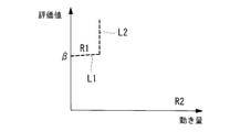
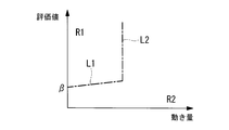
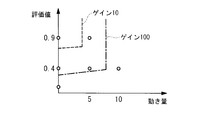
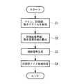
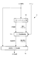
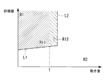
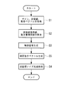
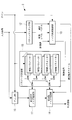
- FIG. 1 It is a block diagram which shows the microscope which concerns on one Embodiment of this invention. It is a block diagram which shows the image processing apparatus which concerns on one Embodiment of this invention with which the microscope of FIG. 1 is equipped. It is a figure which shows an example of the evaluation value boundary line and motion amount boundary line in case the gain with which the noise reduction control part of the image processing apparatus of FIG. It is a figure which shows an example of the evaluation value boundary line and motion amount boundary line in case the gain with which the noise reduction control part of the image processing apparatus of FIG. It is the figure which overlapped Drawing 3A and Drawing 3B, and plotted a plurality of states. 3 is a flowchart illustrating an image processing method by the image processing apparatus of FIG. 2.
- the microscope 1 is, for example, a fluorescence microscope, and an image acquisition unit 2 that acquires fluorescent images in time series, and a fluorescent image acquired by the image acquisition unit 2 And a display unit 4 for displaying a fluorescent image processed by the image processing device 3.
- reference numeral 5 denotes a light source unit.
- the image acquisition unit 2 irradiates the sample 6 on the stage 6 with the stage 6 on which the sample A is mounted, the excitation light from the light source unit 5, and collects the fluorescence generated in the sample A, and the collection lens.
- a fluorescence mirror unit 8 that separates the emitted fluorescence from the optical path of the excitation light and an imaging unit 9 that captures the separated fluorescence are provided.
- the imaging unit 9 sequentially outputs fluorescent images acquired in time series and outputs a gain value applied to each fluorescent image.
- the gain value is a value for adjusting the brightness by multiplying the fluorescence image acquired by the imaging unit 9 in order to generate an appropriate image that is easy for the observer to visually recognize according to the luminance.
- the stage 6 is provided with a Z adjustment mechanism 10 that moves the specimen A in the optical axis direction and an XY adjustment mechanism 11 that moves the specimen A in two directions orthogonal to the optical axis.
- the image processing apparatus 3 has a fluorescence image (first image) of the current frame sent from the image acquisition unit 2 and immediately before being stored in a memory (not shown).
- a pattern matching unit 12 that performs a pattern matching process using a fluorescent image (second image) of a frame (past frame) as an input image, and noise based on an evaluation value and a motion vector output from the pattern matching unit 12
- a noise reduction control unit (control unit) 13 that generates a control signal for performing the reduction process, and cyclic noise reduction processing is performed on the image of the current frame based on the control signal generated by the noise reduction control unit 13.
- a cyclic noise reduction unit 14 to be applied.
- the pattern matching unit 12 performs, for example, a pattern matching process using a known ZNCC (zero average normalized cross correlation) calculation.
- the ZNCC operation is performed by Equation 1.
- the pattern matching process may be performed on the entire fluorescent image or may be performed partially.
- the largest ZNCC value is output from the pattern matching unit 12 as an evaluation value representing the likelihood of the motion vector, and (dx, dy) at that time is output as the motion vector. It has become.
- the ZNCC value is a numerical value of 1 or less, but when the ZNCC value is negative, the evaluation value is 0, and the evaluation value is output as a numerical value of 0 or more and 1 or less. In this embodiment, 0 or less is clipped, but it is not necessary to clip.
- the noise reduction control unit 13 is a signal that controls the cyclic amount of the cyclic noise reduction processing based on the gain input from the image acquisition unit 2 and the evaluation value and motion vector input from the pattern matching unit 12. Is supposed to generate. Specifically, as shown in FIG. 3A to FIG. 3C, an evaluation value boundary that divides the evaluation value into two large and small parts on the coordinate plane having the motion amount indicating the magnitude of the motion vector and the evaluation value as coordinate axes. The amount of circulation is made different between the first region R1 and the second region R2 defined by the line L1 and the motion amount boundary line L2 that divides the motion amount into two.
- the amount of motion is determined as follows using the acquired motion vector (dx, dy). If
- , the amount of motion
- , the amount of motion
- dx + dy or ⁇ (dx 2 + dy 2 ) or the like may be employed as the amount of motion.
- FIG. 3A shows the first region R1 and the second region R2 when the gain is 10
- FIG. 3B shows the first region R1 and the second region R2 when the gain is 100
- FIG. FIG. 3B is a view superimposed on FIG. 3B.
- the first region R1 is a region where the evaluation value is larger than the evaluation value boundary line L1 and the motion amount is smaller than the motion amount boundary line L2
- the second region R2 is a region other than the first region R1. It is.
- the evaluation value boundary line L1 is a linear function that monotonously increases (in the present embodiment, it is a linear function as an example, but may be a quadratic function, etc.).
- the size of the first region R1 is set to increase as the gain increases. That is, when the gain increases, the evaluation value boundary line L1 moves in the direction in which the intercept ⁇ decreases, and the motion amount boundary line L2 moves in the direction in which the threshold value ⁇ increases. Also, ⁇ may be reduced to increase the region R1.
- the noise reduction control part 13 has memorize
- the evaluation value boundary line L1 and the motion amount boundary line L2 selected by the gain determine whether the evaluation value and the motion amount belong to the first region R1 or the second region R2, and when it belongs to the first region R1 Outputs a control signal “0”, and if it belongs to the second region R2, it outputs a control signal “1”.
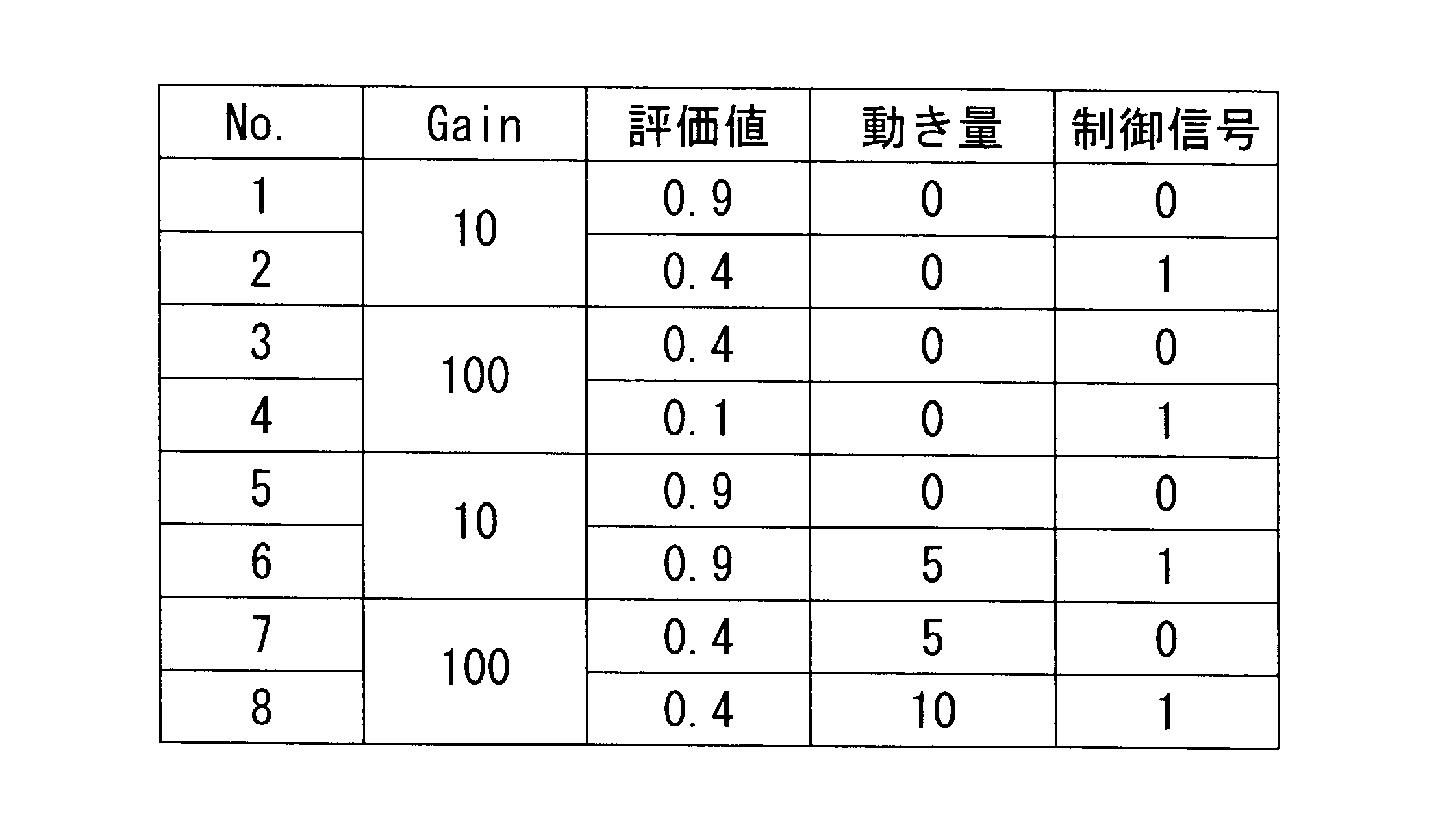
- Table 1 shows an example of the control signal selected according to the gain, evaluation value, and motion amount shown in FIG. 3C.
- the cyclic noise reduction unit 14 generates a cyclic image (noise reduced image) by mixing the input image and the past cyclic image with a cyclic amount corresponding to the control signal input from the noise reduction control unit 13.
- a cyclic image is output, and the output cyclic image is handled as a past cyclic image.
- the cyclic noise reduction unit 14 performs a cyclic noise reduction process by a known method. That is, a cyclic image is generated, and the cyclic image and the input image are mixed and output by the cyclic amount according to the control signal, and the cyclic image is generated. Before the images are mixed, the cyclic image and the input image are aligned.
- step S1 An image processing method by the image processing apparatus 3 according to the present embodiment configured as described above will be described below.
- pattern matching is performed based on the input image.
- a pattern matching process is performed in the unit 12, and an evaluation value and a motion vector are acquired (step S1).
- step S2 when the evaluation value and motion vector output from the pattern matching unit 12 and the gain input from the image acquisition unit 2 are input to the noise reduction control unit 13, the evaluation value boundary line L1 and the gain are input according to the gain.
- a motion amount boundary line L2 is calculated (step S2), it is determined whether the evaluation value and the motion amount belong to the first region R1 or the second region R2, and a control signal is generated (step S3).
- the generated control signal is input to the cyclic noise reduction unit 14 a cyclic amount is set according to the control signal, and cyclic noise reduction processing is performed (step S4).
- the cyclic amount in the cyclic noise reduction process refers to not only the motion vector but also the evaluation value indicating the certainty of the motion vector at the same time. Therefore, even in the case of observing a low-luminance subject, there is an advantage that the amount of patrol can be appropriately controlled and an image with high visibility can be acquired.
- ⁇ described in FIGS. 3A to 3C is set such that ⁇ > 0, so that motion vectors can be distinguished even with the same evaluation value, and better control can be executed.
- noise increases as the gain increases. Therefore, the visibility is improved by expanding the first region R1 and performing the noise reduction processing by performing alignment even in a state where the evaluation value is small. There is an advantage that it can be improved.
- the alignment of the specimen A movement by the XY adjustment mechanism 11 is not performed when the gain is 10 and the probability of the motion vector is high. Therefore, image alignment is hindered.
- the probability of the vector is low, and it is difficult to observe an image unless noise is reduced by performing alignment even in a low state.
- the influence of the focus blur is larger when the gain is 10, and the image observation is hindered unless the judgment of the blur is performed carefully in a state where the probability of the motion vector is high.
- the gain is 100, the probability of motion vector is low even in the in-focus state, making it difficult to discriminate from the blur. become.
- the microscope 1 since the cyclic amount is controlled by the evaluation value boundary line L1 and the motion amount boundary line L2 according to the gain, it is easy to observe an image with high visibility from low gain to high gain. There is an advantage that the performance can be improved.
- the gains are 10 and 100 has been described.
- the present invention is not limited to this, and other arbitrary gains may be switched, and the number of gains may be 3 or more. It may be set.
- the noise reduction control unit 13 outputs only the control signal. Instead, as shown in FIG. 5, a corrected motion vector is output in addition to the control signal. Good.
- the corrected motion vector further divides the first region R1 into two by a threshold value, and adopts different values for a region where the motion amount is smaller than the threshold value and a region where the motion amount is greater than or equal to the threshold value T.
- the corrected motion vector in the region R11 where the motion amount is smaller than the threshold T is (0, 0)
- the corrected motion vector in the region R12 where the motion amount is equal to or greater than the threshold T is (dx, dy).
- the alignment is performed by assuming that the stationary motion is detected by the corrected motion vector even if the actual motion amount exists.
- the region R12 where the amount of motion is greater than or equal to the threshold value T alignment is performed using the same corrected motion vector as the actual motion vector.
- step S3 when it is determined that the image belongs to the first region R1 according to the control signal generated in step S3, the motion vector calculated in step S1 is corrected by the threshold value. A motion vector is generated (step S5), and cyclic noise reduction processing in step S4 is performed.
- the parameter setting unit 15 having a cyclic amount may be further provided, and the parameters may be switched according to the control signal.
- a parameter that holds a greater amount of circulation in the case of the control signal “0” than in the case of the control signal “1” is held.
- the pattern matching unit 12 outputs the brightness information of the first image and the second image as the video level (step S6), and the noise reduction control unit 13
- the brightness change between the first image and the second image may be calculated (step S7), and a control signal for reducing the amount of circulation may be output when the brightness change is larger than a predetermined threshold.
- the brightness change is calculated by dividing the video level of the first image by the video level of the second image.
- reference numeral 16 denotes an amplifier unit.
- the amplifier unit 16 is not always necessary.
- the amplifier unit 16 may be provided only for the input image, or the amplifier unit 16 may be added separately in the flow of pattern matching.
- cyclic noise reduction unit 14 only the cyclic noise reduction unit 14 is provided.
- An acyclic noise reduction unit 17 that performs noise reduction processing by performing interpolation processing, averaging processing, and the like using image data of one input image may be arranged.
- the parameter setting unit 15 may also hold the parameters of the non-cyclic noise reduction unit 17 and switch them according to the control signal.
- the parameters are switched so that the noise reduction processing by the cyclic noise reduction unit 14 is strong and the noise reduction processing by the non-cyclic noise reduction unit 17 is weak.
- the amount of patrol is large, it is close to a stationary state and it is desired to observe the image in detail, so the non-circular noise reduction processing can be weakened to prevent a decrease in resolution.
- the noise reduction processing by the cyclic noise reduction unit 14 is weakened (or the cyclic amount is set to “0”), and the noise reduction processing by the non-cyclic noise reduction unit 17 is strengthened.
- the parameter can be switched to In this state, the microscope 1 is moving the sample A in the X and Y directions or is adjusting the focus. Therefore, the cyclic noise reduction processing is weakened, and the non-cyclic noise reduction processing is strengthened to reduce the afterimage. Can be operated smoothly.
- the parameters provided in the parameter setting unit 15 may be changed according to the gain.
- gain information may be included in the control information. Since the amount of noise varies depending on the gain, it is possible to achieve appropriate noise reduction for all gains by setting a parameter that provides an appropriate amount of noise reduction for each gain.
- the fluorescence image of the immediately preceding frame is adopted as the past image delayed from the input image that is input to the pattern matching unit 12, but instead, as shown in FIG. A past cyclic image input from the cyclic noise reduction unit 14 may be employed.
- a RAW image or a color image obtained by developing a RAW image may be employed as an image input to the pattern matching unit 12 or the cyclic noise reduction unit 14.
- a RAW image may be input to the pattern matching unit 12 and a color image obtained by developing the RAW image may be input to the cyclic noise reduction unit 14.
- an image subjected to image processing suitable for each image may be employed.
- an image subjected to pixel defect correction processing may be input to the pattern matching unit 12, and an image subjected to pixel defect correction processing and white balance processing may be input to the cyclic noise reduction unit 14.
Landscapes
- Engineering & Computer Science (AREA)
- Multimedia (AREA)
- Theoretical Computer Science (AREA)
- Physics & Mathematics (AREA)
- General Physics & Mathematics (AREA)
- Signal Processing (AREA)
- Health & Medical Sciences (AREA)
- General Health & Medical Sciences (AREA)
- Computer Vision & Pattern Recognition (AREA)
- Artificial Intelligence (AREA)
- Vascular Medicine (AREA)
- Computing Systems (AREA)
- Databases & Information Systems (AREA)
- Evolutionary Computation (AREA)
- Medical Informatics (AREA)
- Software Systems (AREA)
- Life Sciences & Earth Sciences (AREA)
- Biomedical Technology (AREA)
- Molecular Biology (AREA)
- Picture Signal Circuits (AREA)
- Studio Devices (AREA)
- Microscoopes, Condenser (AREA)
Abstract
低輝度の被写体であってもスムーズに観察することを目的として、本発明に係る画像処理装置(3)は、第1の画像と、該第1の画像より前に取得された第2の画像との間でパターンマッチング処理を行い、画像間の動きベクトルと該動きベクトルの確からしさを示す評価値とを出力するパターンマッチング部(12)と、前記第1の画像にノイズ低減処理を施したノイズ低減画像を出力する巡回型ノイズ低減部(14)であって、第1の画像に基づく画像と過去のノイズ低減画像に基づく画像とを所定の巡回量に応じて混合するノイズ低減処理を行う巡回型ノイズ低減部(14)と、パターンマッチング部(12)により出力された動きベクトルおよび評価値と、第1の画像にかけられて明るさを調節するゲインとに基づいて、巡回型ノイズ低減部(14)の巡回量を制御する制御部(13)とを備える。
Description
本発明は、画像処理装置、画像処理方法および顕微鏡に関するものである。
巡回型ノイズ低減部および非巡回型ノイズ低減部を備え、映像信号のレベルと動き量または、ゲインと動き量に応じて、巡回量やフィルタ係数を切り替える画像処理装置が知られている(例えば、特許文献1参照。)。
また、巡回型ノイズ低減部を備え、ゲインと複数の閾値との対応関係に基づいて、巡回量を制御する画像処理装置が知られている(例えば、特許文献2参照。)。
また、巡回型ノイズ低減部を備え、ゲインと複数の閾値との対応関係に基づいて、巡回量を制御する画像処理装置が知られている(例えば、特許文献2参照。)。
特許文献1、2の画像処理装置は、ゲインと動き量に応じて、巡回型ノイズ低減部によるノイズ低減の効果を切り替えるものであるが、低輝度の被写体を観察する際には、高いゲインをかけて観察するため、画像のノイズが大きくなって、動きベクトルが正しく算出できない。その結果、巡回型ノイズ低減部の巡回量を正しく制御することが困難である。
本発明は上述した事情に鑑みてなされたものであって、低輝度の被写体であってもスムーズに観察することができる画像処理装置、画像処理方法および顕微鏡を提供することを目的としている。
本発明の一態様は、第1の画像と、該第1の画像より前に取得された第2の画像との間でパターンマッチング処理を行い、前記画像間の動きベクトルと該動きベクトルの確からしさを示す評価値とを出力するパターンマッチング部と、前記第1の画像にノイズ低減処理を施したノイズ低減画像を出力する巡回型ノイズ低減部であって、前記第1の画像に基づく画像と過去のノイズ低減画像に基づく画像とを所定の巡回量に応じて混合するノイズ低減処理を行う巡回型ノイズ低減部と、前記パターンマッチング部により出力された前記動きベクトルおよび前記評価値と、前記第1の画像にかけられて明るさを調節するゲインとに基づいて、前記巡回型ノイズ低減部の巡回量を制御する制御部とを備える画像処理装置である。
本態様によれば、時系列に取得された第1の画像と第2の画像とがパターンマッチング部においてパターンマッチング処理され、画像間の動きベクトルと、その確からしさを示す評価値とが出力される。そして、制御部において、パターンマッチング部から出力されてきた動きベクトルと評価値および第1の画像の明るさを調節するゲインとに基づいて、第1の画像または第1の画像に画像処理を施した画像と、過去のノイズ低減画像または過去のノイズ低減画像に画像処理を施した画像とを所定の巡回量に応じて混合してノイズ低減処理を行う巡回型ノイズ低減部の巡回量が制御される。
低輝度の被写体を観察する際には、画像に高いゲインがかけられる。その場合には画像にノイズが大きくなるため動きベクトルが正しく算出できず、動きベクトルのみでは巡回型ノイズ低減部の巡回量を正しく制御することが困難となる。動きベクトルに加えてその確からしさを示す評価値を用いることで、同じ動きベクトルでも評価値が異なれば異なる巡回量を設定でき、同じ評価値でも動きベクトルが異なれば異なる巡回量を設定できる。その結果、ゲインが高い場合の巡回量を適正に制御し、視認性の高い画像を取得することができる。
上記態様においては、前記制御部が、前記評価値と前記動きベクトルの大きさを示す動き量とを座標軸とする座標平面において、前記評価値を大小2つに区画する評価値境界線と、前記動き量を大小2つに区画する動き量境界線とにより区画された、前記評価値が大きく前記動き量が小さい第1領域において、該第1領域以外の第2領域よりも前記巡回量が大きくなるように制御してもよい。
このようにすることで、評価値と動き量とが第1領域に配置されているときには、巡回量を大きくし、第2領域に配置されているときにはそれよりも巡回量を小さくすることで、視認性が良い画像が生成される。
また、上記態様においては、前記評価値境界線は、前記動き量が大きくなるほど大きい前記評価値において前記第1領域と前記第2領域とを区画するように設定されていてもよい。
このようにすることで、評価値境界線近傍では、同じ評価値でも動き量が小さいほど巡回量が大きくされる範囲が広がる。これにより、高ゲインの特に静止状態において、視認性の高い画像を取得することができる。
このようにすることで、評価値境界線近傍では、同じ評価値でも動き量が小さいほど巡回量が大きくされる範囲が広がる。これにより、高ゲインの特に静止状態において、視認性の高い画像を取得することができる。
また、上記態様においては、前記制御部は、前記ゲインが大きくなるほど、前記評価値境界線を前記評価値が小さい位置に、前記動き量境界線を前記動き量が大きい位置に設定してもよい。
このようにすることで、ゲインが大きくなるほど、第1領域を広げることにより、巡回量を大きくする範囲を広げることができる。
このようにすることで、ゲインが大きくなるほど、第1領域を広げることにより、巡回量を大きくする範囲を広げることができる。
ゲインが小さいときにはノイズが少ないので、精度よく位置合わせされる、より狭い範囲での巡回型のノイズ低減処理が要求される一方、ゲインが大きいときにはノイズが多いので、動きベクトルの確からしさが低い状態でもノイズ低減を図る必要がある。ゲインによって巡回量を大きくする領域が変更され、低ゲインから高ゲインまでの広い範囲にわたって視認性の高い画像を取得することができる。
また、上記態様においては、前記制御部は、前記評価値および前記動き量が前記第1領域内に配置されている場合に、前記動き量が、前記ゲイン毎に定められた閾値より小さい場合に動きベクトルをゼロベクトルに補正してもよい。
このようにすることで、本来巡回量が大きく設定される第1領域内に配置されても、動き量が閾値より小さい領域で動きベクトルをゼロベクトルにする不感帯を設けることで、動き量の誤差により、巡回型のノイズ低減処理が行われることによって静止状態でも画像に動きが発生してしまうことを防止することができる。
このようにすることで、本来巡回量が大きく設定される第1領域内に配置されても、動き量が閾値より小さい領域で動きベクトルをゼロベクトルにする不感帯を設けることで、動き量の誤差により、巡回型のノイズ低減処理が行われることによって静止状態でも画像に動きが発生してしまうことを防止することができる。
また、上記態様においては、前記パターンマッチング部が、前記第1の画像および前記第2の画像の明るさ情報を出力し、前記制御部は、前記パターンマッチング部から出力された明るさ情報に基づいて前記第1の画像と前記第2の画像との間の明るさ変化が所定の閾値より大きい場合に前記巡回量を減少させるように制御してもよい。
このようにすることで、第1の画像と第2の画像との間の明るさ変化が急峻である場合に、巡回量を減少させるように制御して、巡回型のノイズ低減処理においてアーティファクトの発生を防止することができる。
このようにすることで、第1の画像と第2の画像との間の明るさ変化が急峻である場合に、巡回量を減少させるように制御して、巡回型のノイズ低減処理においてアーティファクトの発生を防止することができる。
また、上記態様においては、1枚の前記第1の画像を用いてノイズ低減処理を行う非巡回型ノイズ低減部を備え、前記制御部は、前記評価値および前記動き量が前記第1領域内に配置されている場合に、前記巡回型ノイズ低減部によるノイズ低減処理を前記非巡回型ノイズ低減部によるノイズ低減処理より強くし、前記評価値および前記動き量が前記第2領域内に配置されている場合に、前記非巡回型ノイズ低減部によるノイズ低減処理を前記巡回型ノイズ低減部によるノイズ低減処理より強くするように制御してもよい。
このようにすることで、巡回量を大きくしていない第2領域においても非巡回型のノイズ低減処理によりノイズを抑えることができる。特に動きの大きな状態で画像の視認性を改善することができる。
このようにすることで、巡回量を大きくしていない第2領域においても非巡回型のノイズ低減処理によりノイズを抑えることができる。特に動きの大きな状態で画像の視認性を改善することができる。
また、上記態様においては、前記制御部は、前記ゲインが大きくなるほど、前記巡回型ノイズ低減部および前記非巡回型ノイズ低減部によるノイズ低減処理が強くなるように制御してもよい。
このようにすることで、ゲインに関わらず残像による画質劣化の少ない良好なノイズ量の画質を確保することができる。
このようにすることで、ゲインに関わらず残像による画質劣化の少ない良好なノイズ量の画質を確保することができる。
また、上記態様においては、前記第2の画像が前記巡回型ノイズ低減部により出力される前記ノイズ低減画像であってもよい。
また、上記態様においては、前記第2の画像が前記第1の画像よりも過去に取得された過去フレーム画像であってもよい。
また、上記態様においては、前記第2の画像が前記第1の画像よりも過去に取得された過去フレーム画像であってもよい。
また、本発明の他の態様は、第1の画像と、該第1の画像より前に取得された第2の画像との間でパターンマッチング処理を行って、前記画像間の動きベクトルと該動きベクトルの確からしさを示す評価値とを算出し、算出された前記動きベクトルおよび前記評価値に基づいて、該評価値と前記動きベクトルの大きさを示す動き量とを座標軸とする座標平面において、前記評価値を大小2つに区画する評価値境界線と、前記動き量を大小2つに区画する動き量境界線とにより区画された、前記評価値が大きく前記動き量が小さい第1領域において、該第1領域以外の第2領域よりも巡回量を大きくして巡回型のノイズ低減処理を行う画像処理方法である。
上記態様においては、前記評価値境界線は、前記動き量が大きくなるほど大きい前記評価値において前記第1領域と前記第2領域とを区画するように設定されていてもよい。
また、上記態様においては、ゲインが大きくなるほど、前記評価値境界線を前記評価値が小さい位置に、前記動き量境界線を前記動き量が大きい位置に設定してもよい。
また、上記態様においては、ゲインが大きくなるほど、前記評価値境界線を前記評価値が小さい位置に、前記動き量境界線を前記動き量が大きい位置に設定してもよい。
また、上記態様においては、前記評価値および前記動き量が前記第1領域内に配置されている場合に、前記動き量が、前記ゲイン毎に定められた閾値より小さい場合に動きベクトルをゼロベクトルに補正してもよい。
また、上記態様においては、前記第1の画像と前記第2の画像と間の明るさ変化を検出し、検出された明るさ変化が所定の閾値より大きい場合に前記巡回量を減少させるように制御してもよい。
また、上記態様においては、前記第1の画像と前記第2の画像と間の明るさ変化を検出し、検出された明るさ変化が所定の閾値より大きい場合に前記巡回量を減少させるように制御してもよい。
また、上記態様においては、前記評価値および前記動き量が前記第1領域内に配置されている場合に、巡回型のノイズ低減処理を非巡回型のノイズ低減処理より強くし、前記評価値および前記動き量が前記第2領域内に配置されている場合に、非巡回型のノイズ低減処理を巡回型のノイズ低減処理より強くするように制御してもよい。
また、上記態様においては、ゲインが大きくなるほど、巡回型のノイズ低減処理および非巡回型のノイズ低減処理が強くなるように制御してもよい。
また、本発明の他の態様は、第1の画像および第2の画像を時系列に取得する画像取得部と、上記いずれかの画像処理装置とを備える顕微鏡である。
また、本発明の他の態様は、第1の画像および第2の画像を時系列に取得する画像取得部と、上記いずれかの画像処理装置とを備える顕微鏡である。
本発明によれば、低輝度の被写体であってもスムーズに観察することができるという効果を奏する。
本発明の一実施形態に係る画像処理装置3および顕微鏡1について、図面を参照して以下に説明する。
本実施形態に係る顕微鏡1は、図1に示されるように、例えば、蛍光顕微鏡であって、蛍光画像を時系列に取得する画像取得部2と、該画像取得部2により取得された蛍光画像を処理する画像処理装置3と、該画像処理装置3により処理された蛍光画像を表示する表示部4とを備えている。図中、符号5は光源部である。
本実施形態に係る顕微鏡1は、図1に示されるように、例えば、蛍光顕微鏡であって、蛍光画像を時系列に取得する画像取得部2と、該画像取得部2により取得された蛍光画像を処理する画像処理装置3と、該画像処理装置3により処理された蛍光画像を表示する表示部4とを備えている。図中、符号5は光源部である。
画像取得部2は、標本Aを搭載するステージ6と、光源部5からの励起光をステージ6上の標本Aに照射する一方、標本Aにおいて発生した蛍光を集光する対物レンズ7と、集光された蛍光を励起光の光路から分離する蛍光ミラーユニット8と、分離された蛍光を撮影する撮像部9とを備えている。
撮像部9は、時系列に取得された蛍光画像を順次出力するとともに、各蛍光画像にかけられたゲイン値を出力するようになっている。また、ゲイン値とは、輝度に応じて、観察者が視認しやすい適正な画像を生成するために、撮像部9によって取得された蛍光画像に乗算して明るさを調節するための値である。
ステージ6には標本Aを光軸方向に移動させるZ調整機構10と、光軸に直交する2方向に移動させるXY調整機構11とが設けられている。
ステージ6には標本Aを光軸方向に移動させるZ調整機構10と、光軸に直交する2方向に移動させるXY調整機構11とが設けられている。
本実施形態に係る画像処理装置3は、図2に示されるように、画像取得部2から送られてくる現フレームの蛍光画像(第1の画像)と、図示しないメモリに記憶されていた直前フレーム(過去フレーム)の蛍光画像(第2の画像)とを入力画像として、パターンマッチング処理を行うパターンマッチング部12と、該パターンマッチング部12から出力された評価値および動きベクトルに基づいて、ノイズ低減処理を行うための制御信号を生成するノイズ低減制御部(制御部)13と、該ノイズ低減制御部13により生成された制御信号に基づいて、現フレームの画像に巡回型のノイズ低減処理を施す巡回型ノイズ低減部14とを備えている。
パターンマッチング部12は、例えば、公知のZNCC(ゼロ平均正規化相互相関)演算を利用したパターンマッチング処理を行うようになっている。
ZNCC演算は数1により行われる。
ZNCC演算は数1により行われる。

パターンマッチング処理は、蛍光画像全体で行われてもよいし、部分的におこなわれてもよい。
パターンマッチング処理が行われると、パターンマッチング部12からは、最も大きいZNCC値が、動きベクトルの確からしさを表す評価値として出力され、そのときの(dx,dy)が動きベクトルとして出力されるようになっている。ZNCC値は1以下の数値となるが、ZNCC値が負の場合には評価値を0とし、0以上1以下の数値として評価値を出力するようになっている。本実施例では、0以下をクリップしているがクリップしなくてもよい。
パターンマッチング処理が行われると、パターンマッチング部12からは、最も大きいZNCC値が、動きベクトルの確からしさを表す評価値として出力され、そのときの(dx,dy)が動きベクトルとして出力されるようになっている。ZNCC値は1以下の数値となるが、ZNCC値が負の場合には評価値を0とし、0以上1以下の数値として評価値を出力するようになっている。本実施例では、0以下をクリップしているがクリップしなくてもよい。
ノイズ低減制御部13は、画像取得部2から入力されてきたゲインと、パターンマッチング部12から入力されてきた評価値および動きベクトルとに基づいて、巡回型ノイズ低減処理の巡回量を制御する信号を生成するようになっている。
具体的には、図3Aから図3Cに示されるように、動きベクトルの大きさを示す動き量と、評価値とを座標軸とする座標平面において、評価値を大小2つに区画する評価値境界線L1と、動き量を大小2つに区画する動き量境界線L2とにより区画された第1領域R1および第2領域R2において巡回量を異ならせるようになっている。
具体的には、図3Aから図3Cに示されるように、動きベクトルの大きさを示す動き量と、評価値とを座標軸とする座標平面において、評価値を大小2つに区画する評価値境界線L1と、動き量を大小2つに区画する動き量境界線L2とにより区画された第1領域R1および第2領域R2において巡回量を異ならせるようになっている。
動き量は、取得された動きベクトル(dx,dy)を用いて、以下の通りに決定している。
|dx|>|dy|の場合には、動き量=|dx|、
|dx|≦|dy|の場合には、動き量=|dy|
である。
動き量としては、この他、dx+dy、あるいは、√(dx2+dy2)等を採用してもよい。
|dx|>|dy|の場合には、動き量=|dx|、
|dx|≦|dy|の場合には、動き量=|dy|
である。
動き量としては、この他、dx+dy、あるいは、√(dx2+dy2)等を採用してもよい。
図3Aはゲインが10である場合の第1領域R1および第2領域R2を示し、図3Bはゲインが100である場合の第1領域R1および第2領域R2を示し、図3Cは図3Aと図3Bとを重ねた図を示している。
図3Aおよび図3Bによれば、第1領域R1は評価値が評価値境界線L1より大きく動き量が動き量境界線L2より小さい領域であり、第2領域R2は第1領域R1以外の領域である。
図3Aおよび図3Bによれば、第1領域R1は評価値が評価値境界線L1より大きく動き量が動き量境界線L2より小さい領域であり、第2領域R2は第1領域R1以外の領域である。
また、図3Aから図3Cに示されるように、評価値境界線L1は、単調増加する一次関数、(本実施例では、一例として、1次関数であるが、2次関数等でもよい。)
y=αx+β、(α≧0)
として設定されている。
また、動き量境界線L2は、一定の閾値、
x=γ
として設定されている。
y=αx+β、(α≧0)
として設定されている。
また、動き量境界線L2は、一定の閾値、
x=γ
として設定されている。
図3Cに示されるように、第1領域R1の大きさは、ゲインが大きくなるほど大きく設定されている。すなわち、ゲインが大きくなると、評価値境界線L1は切片βが小さくなる方向に移動し、動き量境界線L2は閾値γが大きくなる方向に移動している。また、αを小さくしてR1の領域を大きくしてもよい。
そして、ノイズ低減制御部13は、例えば、図3Aから図3Cに記載のゲインに応じたα、β、γのパラメータを記憶していて、評価値、動きベクトルおよびゲインが入力されてくると、ゲインによって選択される評価値境界線L1および動き量境界線L2によって、評価値および動き量が第1領域R1に属するのか第2領域R2に属するのかを判定し、第1領域R1に属する場合には制御信号「0」、第2領域R2に属する場合には制御信号「1」を出力するようになっている。なお、表1に図3Cに示すゲイン、評価値、動き量によって選択される制御信号の一例を示す。
巡回型ノイズ低減部14は、ノイズ低減制御部13から入力されてきた制御信号に応じた巡回量で、入力画像と過去の巡回画像とを混合して巡回画像(ノイズ低減画像)を生成して巡回画像を出力するとともに、出力された該巡回画像を過去の巡回画像として扱うようになっている。
本実施形態においては、制御信号「0」は巡回型ノイズ低減処理を所定の巡回量で実施することを意味し、制御信号「1」は巡回型ノイズ低減処理を実施しない(巡回量=0)であることを意味するものとする。(なお、制御信号を使用して、例えば、制御信号「0」は、巡回量「強」(0.8)とし、制御信号「1」は、巡回量「弱」(0.2)として切替えてもよい。)
本実施形態においては、制御信号「0」は巡回型ノイズ低減処理を所定の巡回量で実施することを意味し、制御信号「1」は巡回型ノイズ低減処理を実施しない(巡回量=0)であることを意味するものとする。(なお、制御信号を使用して、例えば、制御信号「0」は、巡回量「強」(0.8)とし、制御信号「1」は、巡回量「弱」(0.2)として切替えてもよい。)
巡回型ノイズ低減部14は、公知の方法で巡回型ノイズ低減処理を行う。すなわち、巡回画像を生成し、巡回画像と入力画像とを制御信号に従う巡回量だけ混合して出力するとともに、巡回画像を生成する。画像を混合する前には、巡回画像と入力画像との位置合わせを行っている。
このように構成された本実施形態に係る画像処理装置3による画像処理方法について以下に説明する。
本実施形態に係る画像処理方法によって標本Aの観察を行うには、図4に示されるように、画像取得部2から入力画像とゲインとが入力されてくると、入力画像に基づいてパターンマッチング部12においてパターンマッチング処理が行われ、評価値および動きベクトルが取得される(ステップS1)。
本実施形態に係る画像処理方法によって標本Aの観察を行うには、図4に示されるように、画像取得部2から入力画像とゲインとが入力されてくると、入力画像に基づいてパターンマッチング部12においてパターンマッチング処理が行われ、評価値および動きベクトルが取得される(ステップS1)。
次いで、パターンマッチング部12から出力された評価値および動きベクトルと、画像取得部2から入力されてきたゲインとがノイズ低減制御部13に入力されると、ゲインに応じて評価値境界線L1および動き量境界線L2が算出され(ステップS2)、評価値および動き量が第1領域R1または第2領域R2のいずれに属するかが判定されて、制御信号が生成される(ステップS3)。
そして、生成された制御信号が巡回型ノイズ低減部14に入力されることにより、制御信号に応じて巡回量が設定されて巡回型のノイズ低減処理が行われる(ステップS4)。
そして、生成された制御信号が巡回型ノイズ低減部14に入力されることにより、制御信号に応じて巡回量が設定されて巡回型のノイズ低減処理が行われる(ステップS4)。
このように、本実施形態に係る画像処理装置3および画像処理方法によれば、巡回型のノイズ低減処理における巡回量を動きベクトルのみならず、動きベクトルの確かさを示す評価値も同時に参照するので、低輝度の被写体を観察する場合においても、巡回量を適正に制御し、視認性の高い画像を取得することができるという利点がある。
すなわち、低輝度の被写体を観察する際には、画像に高いゲインがかけられる。その場合には画像にノイズが大きくなるため、誤差を含む確率が高く、動きベクトルが正しく算出できず、動きベクトルのみでは巡回型ノイズ低減部14の巡回量を正しく制御することが困難となる。
本実施形態によれば、動きベクトルに加えてその確からしさを示す評価値を用いることで、同じ動きベクトルでも評価値が異なれば異なる巡回量を設定でき、同じ評価値でも動きベクトルが異なれば異なる巡回量を設定できる。なお、図3Aから図3Cに記載したαは、α>0とすることで、同じ評価値でも動きベクトルを区別し、よりよい制御を実行することができる。
本実施形態によれば、動きベクトルに加えてその確からしさを示す評価値を用いることで、同じ動きベクトルでも評価値が異なれば異なる巡回量を設定でき、同じ評価値でも動きベクトルが異なれば異なる巡回量を設定できる。なお、図3Aから図3Cに記載したαは、α>0とすることで、同じ評価値でも動きベクトルを区別し、よりよい制御を実行することができる。
また、本実施形態によれば、ゲインが大きくなればノイズが多くなるので、第1領域R1を広げて、評価値が小さい状態でも位置合わせをしてノイズ低減処理を行うことにより、視認性を向上することができるという利点がある。
顕微鏡1においては、XY調整機構11による標本A移動の位置あわせは、ゲインが10の場合の方が動きベクトルの確からしさが高い状態で実施しないと、位置合わせ精度が十分ではなく異なる位置で画像の位置合わせが行われるため画像観察の妨げになる。一方、ゲインが100の場合にはノイズが多いため、ベクトルの確からしさが低い状態となり、低い状態でも位置合わせをしてノイズ低減を図らないと画像観察が困難になる。
また、Z調整機構10による合焦については、フォーカスボケの影響はゲインが10の方が大きく、ボケの判断は動きベクトルの確からしさが高い状態で慎重に行わないと画像観察の妨げになる。一方、ゲインが100の場合には合焦状態でも動きベクトルの確からしさが低い状態となり、ボケとの識別が困難になり、確からしさが低い状態でボケとの識別が行えないと画像観察が困難になる。
本実施形態に係る顕微鏡1によれば、ゲインに応じた評価値境界線L1および動き量境界線L2による巡回量の制御が行われるので、低ゲインから高ゲインまで視認性の高い画像による観察容易性を向上することができるという利点がある。
なお、本実施形態においては、ゲインが10と100の場合について説明したが、これに限定されるものではなく、他の任意のゲインについて切り替えることにしてもよいし、ゲインの数も3以上に設定してもよい。
なお、本実施形態においては、ゲインが10と100の場合について説明したが、これに限定されるものではなく、他の任意のゲインについて切り替えることにしてもよいし、ゲインの数も3以上に設定してもよい。
また、本実施形態においては、ノイズ低減制御部13が制御信号のみを出力したが、これに代えて、図5に示されるように、制御信号に加えて補正動きベクトルを出力することにしてもよい。
補正動きベクトルは、第1領域R1を閾値によってさらに2つに区画し、動き量が閾値より小さい領域と動き量が閾値T以上の領域とで異なる値を採用している。図6に示す例では、動き量が閾値Tより小さい領域R11における補正動きベクトルは(0,0)、動き量が閾値T以上の領域R12における補正動きベクトルは(dx、dy)としている。
補正動きベクトルは、第1領域R1を閾値によってさらに2つに区画し、動き量が閾値より小さい領域と動き量が閾値T以上の領域とで異なる値を採用している。図6に示す例では、動き量が閾値Tより小さい領域R11における補正動きベクトルは(0,0)、動き量が閾値T以上の領域R12における補正動きベクトルは(dx、dy)としている。
これにより、巡回型ノイズ低減部14における画像の位置合わせにおいて、動き量が閾値より小さい領域R11では、実際の動き量が存在していても補正動きベクトルにより静止状態であるとして位置合わせが実施され、動き量が閾値T以上の領域R12では実際の動きベクトルと同じ補正動きベクトルを用いて位置あわせが実施される。
すなわち、図7に示されるように、ステップS3において生成された制御信号に応じて、第1領域R1に属していると判定された場合に、ステップS1において算出された動きベクトルから、閾値によって補正動きベクトルが生成され(ステップS5)、ステップS4における巡回型のノイズ低減処理が行われるようになっている。
これにより、高ゲインの場合には動き量の誤差が発生し易く、静止状態でも画像に動きが発生するので、補正動きベクトルを出力することにより、不感帯を設け、静止状態の画像を実現し、高ゲイン時における静止状態の観察をより容易にすることができる。
また、本実施形態においては、制御信号に応じて巡回型のノイズ低減処理を行うか行わないかを切り替えることとしたが、これに代えて、図8に示されるように、複数のパラメータ(例えば、巡回量)を備えるパラメータ設定部15をさらに備え、制御信号に応じてパラメータを切り替えることにしてもよい。図に示す例では、制御信号「0」の場合に、制御信号「1」の場合より多くの巡回量となるようなパラメータが保持されている。これにより、制御信号「0」の場合には、巡回画像の比率が高くなり、制御信号「1」の場合には現フレームの画像の比率が高くなった画像が出力される。
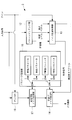
また、図9および図10に示されるように、パターンマッチング部12が、第1の画像および第2の画像の明るさ情報を映像レベルとして出力するとともに(ステップS6)、ノイズ低減制御部13が、第1の画像と第2の画像との間の明るさ変化を算出し(ステップS7)、明るさ変化が所定の閾値より大きい場合に巡回量を減少させる制御信号を出力してもよい。
具体的には、第1の画像の映像レベルを第2の画像の映像レベルで除算することにより明るさ変化を算出する。
具体的には、第1の画像の映像レベルを第2の画像の映像レベルで除算することにより明るさ変化を算出する。
(第1の画像の映像レベル)/(第2の画像の映像レベル)=明るさ変化
上記式により算出された明るさ変化が上限閾値以上または下限閾値以下の場合に(ステップS8、ステップS9)、急峻な明るさ変化であると判定して、第1領域R1に属していても制御信号「1」に設定する(ステップS10)。これにより、出力される画像におけるアーティファクトの発生を抑えることができる。
上記式により算出された明るさ変化が上限閾値以上または下限閾値以下の場合に(ステップS8、ステップS9)、急峻な明るさ変化であると判定して、第1領域R1に属していても制御信号「1」に設定する(ステップS10)。これにより、出力される画像におけるアーティファクトの発生を抑えることができる。
図中、符号16はアンプ部である。アンプ部16は必ずしも必要ではない。アンプ部16は、入力画像のみに対して設けてもよいし、パターンマッチングする流れにアンプ部16を別途追加してもよい。
また、本実施形態においては巡回型ノイズ低減部14のみを設けていたが、これに加えて、図11に示されるように、巡回型ノイズ低減部14の前段に、ノイズ低減処理対象である1枚の入力画像の画像データを用いて補間処理および平均化処理等を実行し、ノイズ低減処理を行う非巡回型ノイズ低減部17を配置してもよい。パラメータ設定部15に非巡回型ノイズ低減部17のパラメータも保持しておき、制御信号に応じて切り替えることにしてもよい。
具体的には、制御信号「0」の場合に、巡回型ノイズ低減部14によるノイズ低減処理を強く、非巡回型ノイズ低減部17によるノイズ低減処理を弱くするようにパラメータが切り替えられる。巡回量が多い場合には、静止状態に近く、画像を詳細に観察したいので、非巡回型のノイズ低減処理を弱くして解像感の低下を防止することができる。
一方、制御信号「1」の場合には、巡回型ノイズ低減部14によるノイズ低減処理を弱く(あるいは巡回量を「0」にし)、非巡回型ノイズ低減部17によるノイズ低減処理を強くするようにパラメータが切り替えられる。この状態は、顕微鏡1ではXY方向に標本Aを移動中であるか、フォーカスを調整中であるため、巡回型のノイズ低減処理を弱く、非巡回型のノイズ低減処理を強くして残像の低減を図り、スムーズな操作を行うことができる。
また、図12に示されるように、パラメータ設定部15に備えるパラメータをゲインに応じて変更することにしてもよい。この場合には、制御情報にゲインの情報も含めることにすればよい。
ゲインに応じてノイズ量が異なるため、ゲイン毎に適正なノイズ低減量となるパラメータを設定することで、全てのゲインにおいて適正なノイズ低減を図ることができる。
ゲインに応じてノイズ量が異なるため、ゲイン毎に適正なノイズ低減量となるパラメータを設定することで、全てのゲインにおいて適正なノイズ低減を図ることができる。
また、本実施形態においては、パターンマッチング部12に入力する、入力画像よりも遅延した過去の画像として、直前フレームの蛍光画像を採用したが、これに代えて、図13に示されるように、巡回型ノイズ低減部14から入力されてきた過去の巡回画像を採用してもよい。
また、本実施形態においては、パターンマッチング部12や巡回型ノイズ低減部14に入力する画像として、RAW画像またはRAW画像を現像処理したカラー画像を採用してもよい。また、パターンマッチング部12にRAW画像が入力され、巡回型ノイズ低減部14にはRAW画像を現像処理したカラー画像が入力されてもよい。
また、パターンマッチング部12や巡回型ノイズ低減部14に入力する画像として、画像毎に適した画像処理を施したものを採用してもよい。例えば、パターンマッチング部12に画素欠陥補正処理を施した画像が入力され、巡回型ノイズ低減部14には画素欠陥補正処理およびホワイトバランス処理を施した画像が入力されてもよい。
1 顕微鏡
2 画像取得部
3 画像処理装置
12 パターンマッチング部
13 ノイズ低減制御部(制御部)
14 巡回型ノイズ低減部
17 非巡回型ノイズ低減部
A 標本
L1 評価値境界線
L2 動き量境界線
R1 第1領域
R2 第2領域
2 画像取得部
3 画像処理装置
12 パターンマッチング部
13 ノイズ低減制御部(制御部)
14 巡回型ノイズ低減部
17 非巡回型ノイズ低減部
A 標本
L1 評価値境界線
L2 動き量境界線
R1 第1領域
R2 第2領域
Claims (18)
- 第1の画像と、該第1の画像より前に取得された第2の画像との間でパターンマッチング処理を行い、前記画像間の動きベクトルと該動きベクトルの確からしさを示す評価値とを出力するパターンマッチング部と、
前記第1の画像にノイズ低減処理を施したノイズ低減画像を出力する巡回型ノイズ低減部であって、前記第1の画像に基づく画像と過去の前記ノイズ低減画像に基づく画像とを所定の巡回量に応じて混合するノイズ低減処理を行う巡回型ノイズ低減部と、
前記パターンマッチング部により出力された前記動きベクトルおよび前記評価値と、前記第1の画像にかけられて明るさを調節するゲインとに基づいて、前記巡回型ノイズ低減部の巡回量を制御する制御部とを備える画像処理装置。 - 前記制御部が、前記評価値と前記動きベクトルの大きさを示す動き量とを座標軸とする座標平面において、前記評価値を大小2つに区画する評価値境界線と、前記動き量を大小2つに区画する動き量境界線とにより区画された、前記評価値が大きく前記動き量が小さい第1領域において、該第1領域以外の第2領域よりも前記巡回量が大きくなるように制御する請求項1に記載の画像処理装置。
- 前記評価値境界線は、前記動き量が大きくなるほど大きい前記評価値において前記第1領域と前記第2領域とを区画するように設定されている請求項2に記載の画像処理装置。
- 前記制御部は、前記ゲインが大きくなるほど、前記評価値境界線を前記評価値が小さい位置に、前記動き量境界線を前記動き量が大きい位置に設定する請求項2または請求項3に記載の画像処理装置。
- 前記制御部は、前記評価値および前記動き量が前記第1領域内に配置されている場合に、前記動き量が、前記ゲイン毎に定められた閾値より小さい場合に動きベクトルをゼロベクトルに補正する請求項4に記載の画像処理装置。
- 前記パターンマッチング部が、前記第1の画像および前記第2の画像の明るさ情報を出力し、
前記制御部は、前記パターンマッチング部から出力された明るさ情報に基づいて、前記第1の画像と前記第2の画像との間の明るさ変化が所定の閾値より大きい場合に前記巡回量を減少させるように制御する請求項1から請求項5のいずれかに記載の画像処理装置。 - 1枚の前記第1の画像を用いてノイズ低減処理を行う非巡回型ノイズ低減部を備え、
前記制御部は、前記評価値および前記動き量が前記第1領域内に配置されている場合に、前記巡回型ノイズ低減部によるノイズ低減処理を前記非巡回型ノイズ低減部によるノイズ低減処理より強くし、前記評価値および前記動き量が前記第2領域内に配置されている場合に、前記非巡回型ノイズ低減部によるノイズ低減処理を前記巡回型ノイズ低減部によるノイズ低減処理より強くするように制御する請求項2または請求項3に記載の画像処理装置。 - 前記制御部は、前記ゲインが大きくなるほど、前記巡回型ノイズ低減部および前記非巡回型ノイズ低減部によるノイズ低減処理が強くなるように制御する請求項7に記載の画像処理装置。
- 前記第2の画像が前記ノイズ低減画像である請求項1から請求項8のいずれかに記載の画像処理装置。
- 前記第2の画像が前記第1の画像よりも前に取得された過去フレーム画像である請求項1から請求項8のいずれかに記載の画像処理装置。
- 第1の画像と、該第1の画像より前に取得された第2の画像との間でパターンマッチング処理を行って、前記画像間の動きベクトルと該動きベクトルの確からしさを示す評価値とを算出し、
算出された前記動きベクトルおよび前記評価値に基づいて、該評価値と前記動きベクトルの大きさを示す動き量とを座標軸とする座標平面において、前記評価値を大小2つに区画する評価値境界線と、前記動き量を大小2つに区画する動き量境界線とにより区画された、前記評価値が大きく前記動き量が小さい第1領域において、該第1領域以外の第2領域よりも巡回量を大きくして巡回型のノイズ低減処理を行う画像処理方法。 - 前記評価値境界線は、前記動き量が大きくなるほど大きい前記評価値において前記第1領域と前記第2領域とを区画するように設定されている請求項11に記載の画像処理方法。
- ゲインが大きくなるほど、前記評価値境界線を前記評価値が小さい位置に、前記動き量境界線を前記動き量が大きい位置に設定する請求項11または請求項12に記載の画像処理方法。
- 前記評価値および前記動き量が前記第1領域内に配置されている場合に、前記動き量が、前記ゲイン毎に定められた閾値より小さい場合に動きベクトルをゼロベクトルに補正する請求項13に記載の画像処理方法。
- 前記第1の画像と前記第2の画像と間の明るさ変化を検出し、
検出された明るさ変化が所定の閾値より大きい場合に前記巡回量を減少させるように制御する請求項11または請求項12に記載の画像処理方法。 - 前記評価値および前記動き量が前記第1領域内に配置されている場合に、巡回型のノイズ低減処理を非巡回型のノイズ低減処理より強くし、前記評価値および前記動き量が前記第2領域内に配置されている場合に、非巡回型のノイズ低減処理を巡回型のノイズ低減処理より強くするように制御する請求項11または請求項12に記載の画像処理方法。
- ゲインが大きくなるほど、巡回型のノイズ低減処理および非巡回型のノイズ低減処理が強くなるように制御する請求項16に記載の画像処理方法。
- 第1の画像および第2の画像を時系列に取得する画像取得部と、
請求項1から請求項10のいずれかに記載の画像処理装置とを備える顕微鏡。
Priority Applications (3)
| Application Number | Priority Date | Filing Date | Title |
|---|---|---|---|
| PCT/JP2015/068735 WO2017002183A1 (ja) | 2015-06-29 | 2015-06-29 | 画像処理装置、画像処理方法および顕微鏡 |
| JP2017525708A JP6438136B2 (ja) | 2015-06-29 | 2015-06-29 | 画像処理装置、画像処理方法および顕微鏡 |
| US15/801,683 US10540754B2 (en) | 2015-06-29 | 2017-11-02 | Image-processing device, image-processing method, and microscope |
Applications Claiming Priority (1)
| Application Number | Priority Date | Filing Date | Title |
|---|---|---|---|
| PCT/JP2015/068735 WO2017002183A1 (ja) | 2015-06-29 | 2015-06-29 | 画像処理装置、画像処理方法および顕微鏡 |
Related Child Applications (1)
| Application Number | Title | Priority Date | Filing Date |
|---|---|---|---|
| US15/801,683 Continuation US10540754B2 (en) | 2015-06-29 | 2017-11-02 | Image-processing device, image-processing method, and microscope |
Publications (1)
| Publication Number | Publication Date |
|---|---|
| WO2017002183A1 true WO2017002183A1 (ja) | 2017-01-05 |
Family
ID=57608245
Family Applications (1)
| Application Number | Title | Priority Date | Filing Date |
|---|---|---|---|
| PCT/JP2015/068735 Ceased WO2017002183A1 (ja) | 2015-06-29 | 2015-06-29 | 画像処理装置、画像処理方法および顕微鏡 |
Country Status (3)
| Country | Link |
|---|---|
| US (1) | US10540754B2 (ja) |
| JP (1) | JP6438136B2 (ja) |
| WO (1) | WO2017002183A1 (ja) |
Families Citing this family (3)
| Publication number | Priority date | Publication date | Assignee | Title |
|---|---|---|---|---|
| WO2020203164A1 (ja) * | 2019-03-29 | 2020-10-08 | ソニー株式会社 | 医療システム、情報処理装置及び情報処理方法 |
| US12256154B2 (en) * | 2020-05-08 | 2025-03-18 | Sony Semiconductor Solutions Corporation | Electronic device and imaging device with image data correction |
| DE112021007544T5 (de) | 2021-04-19 | 2024-03-28 | Hanwha Vision Co., Ltd. | Rauschentfernung für ein überwachungskamerabild mittels ki-basierter objekterkennung |
Citations (4)
| Publication number | Priority date | Publication date | Assignee | Title |
|---|---|---|---|---|
| JP2007288595A (ja) * | 2006-04-18 | 2007-11-01 | Pioneer Electronic Corp | フレーム巡回型ノイズ低減装置 |
| JP2008252760A (ja) * | 2007-03-30 | 2008-10-16 | Sony Corp | 映像信号処理装置と映像信号処理方法 |
| JP2012175385A (ja) * | 2011-02-21 | 2012-09-10 | Canon Inc | 撮像装置、及びその制御方法 |
| JP2013255132A (ja) * | 2012-06-07 | 2013-12-19 | Olympus Corp | 画像処理装置、画像処理方法及びプログラム |
Family Cites Families (4)
| Publication number | Priority date | Publication date | Assignee | Title |
|---|---|---|---|---|
| JP3611773B2 (ja) | 2000-06-22 | 2005-01-19 | 松下電器産業株式会社 | ノイズ低減装置、ノイズ低減方法およびノイズ低減プログラムを記録した媒体 |
| JP5066403B2 (ja) * | 2007-07-31 | 2012-11-07 | 日本コヴィディエン株式会社 | 液体混注具 |
| JP5417746B2 (ja) | 2008-06-19 | 2014-02-19 | ソニー株式会社 | 動き適応型ノイズ低減装置、画像信号処理装置、画像入力処理装置、および、動き適応ノイズ低減方法 |
| JP5576812B2 (ja) * | 2011-02-16 | 2014-08-20 | オリンパス株式会社 | 画像処理装置、画像処理方法、画像処理プログラム、及び、撮像装置 |
-
2015
- 2015-06-29 JP JP2017525708A patent/JP6438136B2/ja active Active
- 2015-06-29 WO PCT/JP2015/068735 patent/WO2017002183A1/ja not_active Ceased
-
2017
- 2017-11-02 US US15/801,683 patent/US10540754B2/en active Active
Patent Citations (4)
| Publication number | Priority date | Publication date | Assignee | Title |
|---|---|---|---|---|
| JP2007288595A (ja) * | 2006-04-18 | 2007-11-01 | Pioneer Electronic Corp | フレーム巡回型ノイズ低減装置 |
| JP2008252760A (ja) * | 2007-03-30 | 2008-10-16 | Sony Corp | 映像信号処理装置と映像信号処理方法 |
| JP2012175385A (ja) * | 2011-02-21 | 2012-09-10 | Canon Inc | 撮像装置、及びその制御方法 |
| JP2013255132A (ja) * | 2012-06-07 | 2013-12-19 | Olympus Corp | 画像処理装置、画像処理方法及びプログラム |
Also Published As
| Publication number | Publication date |
|---|---|
| US20180144443A1 (en) | 2018-05-24 |
| JPWO2017002183A1 (ja) | 2018-03-08 |
| US10540754B2 (en) | 2020-01-21 |
| JP6438136B2 (ja) | 2018-12-12 |
Similar Documents
| Publication | Publication Date | Title |
|---|---|---|
| RU2419243C1 (ru) | Устройство и способ обработки изображений и устройство и способ отображения изображений | |
| US9898803B2 (en) | Image processing apparatus, image processing method, and recording medium storing image processing program | |
| US11769236B2 (en) | Microscopy system and method for generating an HDR image | |
| RU2523028C2 (ru) | Устройство обработки изображения, устройство захвата изображения и способ обработки изображения | |
| RU2461979C2 (ru) | Устройство видеоотображения | |
| US8218888B2 (en) | Motion blur detecting apparatus and method, image processing apparatus, and image display apparatus | |
| US9274328B2 (en) | Image processing apparatus, microscope system, and recording medium | |
| CN104320575A (zh) | 一种用于便携式终端的图像处理方法及图像处理装置 | |
| EP3293697A1 (en) | Image processing device, imaging device, image processing method, and storage medium storing image processing program for image processing device | |
| JP6438136B2 (ja) | 画像処理装置、画像処理方法および顕微鏡 | |
| US20110286680A1 (en) | Medium storing image processing program, image processing device, and image processing method | |
| US20130084005A1 (en) | Image processing device and method for processing image | |
| KR20060019776A (ko) | 디스플레이장치의 제어방법 | |
| WO2019160041A1 (ja) | 画像処理装置、顕微鏡システム、画像処理方法および画像処理プログラム | |
| US20210173193A1 (en) | Observation device and observation method | |
| JP7346077B2 (ja) | 画像処理装置、画像処理方法及びプログラム | |
| EP4538962A2 (en) | Image processing method, image processing apparatus, image processing system, and program | |
| JP7708119B2 (ja) | 情報処理装置、情報処理方法およびプログラム | |
| US10198982B2 (en) | Image processing apparatus, method thereof, and image display apparatus | |
| JP2006308884A (ja) | オートフォーカス装置 | |
| JP5219771B2 (ja) | 映像処理装置および映像処理装置の制御方法 | |
| US8422734B1 (en) | Method for processing images | |
| JP6381212B2 (ja) | 撮像装置及びその制御方法 | |
| JP2014060654A (ja) | 撮像装置、その制御方法、および制御プログラム | |
| JP4486487B2 (ja) | スミア補正装置 |
Legal Events
| Date | Code | Title | Description |
|---|---|---|---|
| 121 | Ep: the epo has been informed by wipo that ep was designated in this application |
Ref document number: 15897110 Country of ref document: EP Kind code of ref document: A1 |
|
| ENP | Entry into the national phase |
Ref document number: 2017525708 Country of ref document: JP Kind code of ref document: A |
|
| NENP | Non-entry into the national phase |
Ref country code: DE |
|
| 122 | Ep: pct application non-entry in european phase |
Ref document number: 15897110 Country of ref document: EP Kind code of ref document: A1 |