WO2016208465A1 - Testing method for dc circuit breaker - Google Patents
Testing method for dc circuit breaker Download PDFInfo
- Publication number
- WO2016208465A1 WO2016208465A1 PCT/JP2016/067736 JP2016067736W WO2016208465A1 WO 2016208465 A1 WO2016208465 A1 WO 2016208465A1 JP 2016067736 W JP2016067736 W JP 2016067736W WO 2016208465 A1 WO2016208465 A1 WO 2016208465A1
- Authority
- WO
- WIPO (PCT)
- Prior art keywords
- current
- circuit
- circuit breaker
- breaker
- voltage
- Prior art date
Links
Images


Classifications
-
- G—PHYSICS
- G01—MEASURING; TESTING
- G01R—MEASURING ELECTRIC VARIABLES; MEASURING MAGNETIC VARIABLES
- G01R31/00—Arrangements for testing electric properties; Arrangements for locating electric faults; Arrangements for electrical testing characterised by what is being tested not provided for elsewhere
- G01R31/327—Testing of circuit interrupters, switches or circuit-breakers
- G01R31/3271—Testing of circuit interrupters, switches or circuit-breakers of high voltage or medium voltage devices
- G01R31/3272—Apparatus, systems or circuits therefor
-
- G—PHYSICS
- G01—MEASURING; TESTING
- G01R—MEASURING ELECTRIC VARIABLES; MEASURING MAGNETIC VARIABLES
- G01R31/00—Arrangements for testing electric properties; Arrangements for locating electric faults; Arrangements for electrical testing characterised by what is being tested not provided for elsewhere
- G01R31/327—Testing of circuit interrupters, switches or circuit-breakers
- G01R31/333—Testing of the switching capacity of high-voltage circuit-breakers ; Testing of breaking capacity or related variables, e.g. post arc current or transient recovery voltage
- G01R31/3333—Apparatus, systems or circuits therefor
- G01R31/3336—Synthetic testing, i.e. with separate current and voltage generators simulating distance fault conditions
Definitions
- Embodiment of this invention is related with the test method for verifying the interruption
- a large-capacity AC circuit breaker is used to protect the system from short-circuit accidents caused by lightning strikes in the AC power system.
- a test method called a synthetic test method is known as an AC circuit breaker test method (for example, see Non-Patent Document 1).
- a current source circuit for supplying a short-circuit current corresponding to an accident current and a voltage source circuit for supplying a high-frequency current and applying a recovery voltage to the AC circuit breaker to be tested are respectively provided. This is performed using a test apparatus connected in parallel.
- the AC circuit breaker breaking test is performed according to the following procedures (1) to (4).
- (1) Supply an AC short circuit current corresponding to an accident current from the current source circuit to the AC circuit breaker.
- (2) A high-frequency current is supplied from the voltage source circuit immediately before the final zero value of the short-circuit current, and a superimposed current is supplied to the AC circuit breaker from the two circuits of the current source circuit and the voltage source circuit.
- (3) The current source circuit is disconnected from the AC circuit breaker when the short-circuit current reaches the final zero value.
- the high-frequency current is interrupted by the AC circuit breaker, and a recovery voltage is generated between the terminals of the AC circuit breaker.
- a DC circuit breaker is used.
- the DC breaker cuts off the accident current due to short circuit.
- the DC circuit breaker is required to have a predetermined breaking performance depending on the DC system used.
- a DC circuit breaker test method has been made to solve the above-described problems, and provides a DC circuit breaker test method for verifying the circuit breaker performance of the DC circuit breaker. With the goal.
- the DC circuit breaker test method of the present embodiment is a DC circuit breaker test method for verifying the circuit breaker performance using a test apparatus including a current source circuit and a voltage source circuit. And supplying at least an AC current from the current source circuit to the DC circuit breaker, and when the current becomes equivalent to an accident current due to a system fault in a DC system, the current is interrupted by the DC circuit breaker. Before the interruption, the voltage source circuit is connected to the DC circuit breaker to apply a voltage to the DC circuit breaker, and simultaneously with the interruption, a recovery voltage is applied from the voltage source circuit.
- the DC circuit breaker test method of the present embodiment is a DC circuit breaker test method for verifying the circuit breaker performance using a test apparatus including a current source circuit and a voltage source circuit, and the DC circuit breaker A current corresponding to an accident current due to a system fault in a DC system is supplied from the current source circuit, the current is interrupted by the DC circuit breaker, and a recovery voltage is applied to the DC circuit breaker from the current source circuit, A DC voltage is applied from the voltage source circuit to the DC circuit breaker while the connection of the current source circuit to the DC circuit breaker is continued and the recovery voltage is applied.
- FIG. 1 is a circuit diagram showing the configuration of a test apparatus for a DC circuit breaker according to this embodiment.
- the DC circuit breaker test device is a device for testing the direct current circuit breaker performance of the DC circuit breaker 1 to be tested.
- the DC circuit breaker testing apparatus according to the present embodiment has the same structure as a synthetic test circuit used for a conventional AC circuit breaker break test. That is, in this embodiment, the AC circuit breaker installed in the composite test circuit is replaced with a DC circuit breaker, and the composite test circuit is used to verify the breaking performance of the DC circuit breaker.
- this test apparatus includes two power supply circuits to be described later in order to simulate the occurrence of a fault in the DC system. Examples of the DC system include DC transmission systems such as long-distance transmission and between power companies, DC distribution such as buildings and large commercial facilities, and DC systems such as electric railways.
- the DC circuit breaker 1 is a circuit breaker that interrupts a direct current flowing through the DC circuit breaker 1.
- the DC circuit breaker 1 includes a breaker 101 and an energy absorber 102.
- the blocking unit 101 and the energy absorbing unit 102 are provided in parallel.
- the circuit breaker 101 is a switch for cutting off / closing current flowing through the circuit.
- the blocking unit 101 includes a semiconductor blocking unit using a semiconductor.
- the shut-off unit 101 may include a mechanical shut-off unit that mechanically shuts off / in addition to the semiconductor shut-off unit.
- the energy absorbing unit 102 is a so-called surge absorber (hereinafter also referred to as a surge absorber 102).
- the surge absorber 102 absorbs transient high voltage energy applied to the surge absorber 102.
- the surge absorber 102 limits the magnitude of the voltage after the interruption unit 101 is interrupted.
- the DC circuit breaker 1 is connected with two different power supply circuits in parallel. That is, the test apparatus according to this embodiment includes a current source circuit A that supplies an alternating current to the DC circuit breaker 1 and a voltage source circuit B that applies a recovery voltage to the DC circuit breaker 1. These circuits A and B are connected in parallel to the DC circuit breaker 1.
- the current source circuit A supplies an AC current to the DC circuit breaker 1.
- the current source circuit A includes a short-circuit generator 2, a protective circuit breaker 3, a closing switch 4, a reactor 5, a resistor 6, a capacitor 7, and an auxiliary circuit breaker 8.
- the short-circuit generator 2 is a generator that generates a short-circuit current.
- the short circuit current generated from the short circuit generator 2 is an alternating current.
- the short-circuit current generated in the short-circuit generator 2 is output to the DC circuit breaker 1 through the reactor 5.
- a protective circuit breaker 3 and a closing switch 4 are provided between the short-circuit generator 2 and the DC circuit breaker 1.
- the input switch 4 is a switch for connecting the short-circuit generator 2 to the test circuit, and switches connection and disconnection of the short-circuit generator 2 to the DC circuit breaker 1.
- the protective circuit breaker 3 is a circuit breaker that blocks AC short-circuit current flowing through the current source circuit A. The protective circuit breaker 3 cuts off at the current zero point of this AC short-circuit current.
- the current source circuit A is provided with an auxiliary circuit breaker 8 and a surge absorber 41.
- the auxiliary circuit breaker 8 is connected to the short circuit generator 2 and switches between connection and disconnection between the DC circuit breaker 1 and the short circuit generator 2 to be tested.
- the auxiliary circuit breaker 8 is, for example, a mechanical circuit breaker.
- the auxiliary circuit breaker 8 is provided closest to the DC circuit breaker 1 among the devices in the current source circuit A. When the auxiliary circuit breaker 8 is in the on state, current can be supplied from the short-circuit generator 2 to the DC circuit breaker 1, and when the auxiliary circuit breaker 8 is in the interruption state, the current source circuit A is connected to the DC circuit breaker 1. The current is not supplied to the DC breaker 1 from the short-circuit generator 2.
- the surge absorber 41 is connected to the auxiliary circuit breaker 8 and absorbs a surge generated when the auxiliary circuit breaker 8 is interrupted.
- the surge absorber 41 is formed by connecting the resistor 6 and the capacitor 7 in series.
- the capacitor 7 absorbs the surge through the resistor 6 and facilitates the interruption by the auxiliary circuit breaker 8.
- the voltage source circuit B applies a recovery voltage to the DC circuit breaker 1.
- the voltage source circuit B includes a voltage source capacitor 10, a charging device 9, a start switch 11, a reactor 12, a resistor 13, and a capacitor 14.
- the voltage source capacitor 10 is a DC capacitor serving as a voltage source for the voltage source circuit B.
- the voltage source capacitor 10 applies a recovery voltage to the DC circuit breaker 1 via the reactor 12 when the start switch 11 is in the on state.
- the voltage source capacitor 10 has a capacity for supplying a part of a short-circuit current at the time of a DC system fault in which the DC circuit breaker 1 is provided.
- the recovery voltage may be used in combination with another capacitor for adjusting the transient recovery voltage.
- the charging device 9 is a device that is connected in parallel with the voltage source capacitor 10 and charges the voltage source capacitor 10.
- the start switch 11 is a device that switches on / off of voltage application from the voltage source capacitor 10.
- the voltage source circuit B includes a transient oscillation circuit (LCR circuit) using the voltage source capacitor 10 as a DC voltage source. That is, the reactor 12, the resistor 13, and the capacitor 14 are connected in series to the voltage source capacitor 10, and constitute a transient vibration circuit.
- This transient vibration circuit adjusts the voltage applied to the DC circuit breaker 1 by generating a transient phenomenon. For this reason, the recovery voltage applied to the DC circuit breaker 1 by the voltage source circuit B is a high-frequency voltage.
- the capacitor 14 is a voltage adjusting capacitor that adjusts the voltage supplied by the voltage source capacitor 10.
- the capacitor 14 is a capacitor that is used in combination with the voltage source capacitor 10 to adjust the voltage applied to the DC circuit breaker 1 when a DC system fault occurs.
- the test method of the present embodiment is a method for verifying the short circuit fault current interrupting performance of a DC system of a DC circuit breaker including a semiconductor circuit breaker.
- the test method 1 and (2) the second test method for verifying the interruption performance after interruption are performed separately.
- a method for testing the instantaneous interruption performance will be described with reference to FIGS.
- FIG. 2 is a current waveform diagram in the process of short-circuit current interruption in the first test method.
- FIG. 3 is a voltage waveform diagram in the process of performing the short-circuit current interruption in the first test method.
- the closing switch 4 is closed, and an alternating current is supplied from the short-circuit generator 2 to the breaking unit 101 of the DC breaker 1.
- This alternating current is 0 A at time A and then increases. The magnitude of this alternating current is adjusted by the reactor 5.
- the start switch 11 is turned on.
- This charging timing is set before the alternating current supplied by the short-circuit generator 2 reaches a peak value. That is, it may be up to 1 ⁇ 4 period of alternating current.
- the current supplied to the interrupting unit 101 before the start switch 11 is turned on is less than the accident current due to the DC system fault.
- the start-up switch 11 may be turned on before the current is interrupted by the interrupting unit 101 of the DC circuit breaker 1 and includes the same time as or immediately before the current interrupting. In this embodiment, the start timing of the start switch 11 is before the current interruption.
- an alternating current having a frequency determined by the voltage source capacitor 10 and the reactor 12 is supplied to the cutoff unit 101. That is, when the start switch 11 is turned on, the voltage source circuit B is connected to the DC circuit breaker, and the AC current from the voltage source circuit B is superimposed on the AC current from the short-circuit generator 2. As shown in FIG. 2, the superimposed current 15 is supplied to the blocking unit 101 and rises. Further, when the start switch 11 is turned on at time B, the voltage source circuit B is connected to the DC circuit breaker 1, whereby a voltage is applied to the DC circuit breaker 1. Since the main power supply of the voltage source circuit B is the voltage source capacitor 10, as shown in FIG. 3, the voltage of the voltage source capacitor 10 decreases due to the discharge.
- the breaker 101 and the auxiliary breaker 8 are opened to cut the current, and the current 15 is cut off.
- the current 15 is interrupted when the current corresponding to the accident current is reached.
- the transient recovery voltage 17 from the voltage source circuit B is applied between the interruption parts 101 of the DC breaker 1, and the surge absorber 102 absorbs the overvoltage, and as shown in FIG.
- the current supplied from the capacitor 10 becomes a surge absorber current 16 and flows to the surge absorber 102.
- the voltage of the voltage source capacitor 10 at time C is equal to or higher than the voltage applied to the DC circuit breaker 1 when the current is interrupted due to an accident in the DC system.
- the start switch 11 is turned on before the current interruption by the DC breaker 1, and the voltage source circuit B is connected to the DC breaker 1 before the interruption.
- a current corresponding to the accident current and a predetermined recovery voltage corresponding to the voltage associated with the accident current interruption may be supplied to the DC circuit breaker 1.
- the connection timing may be simultaneous with the interruption. Even in this way, when the current is interrupted, a current corresponding to the accident current and a predetermined recovery voltage corresponding to the voltage associated with the accident current interruption can be provided.
- the current corresponding to the fault current to the DC circuit breaker 1 is supplied by superimposing the two current source circuits A and the voltage source circuit B. It is also possible to supply only by the circuit A. In this case, the connection of the voltage source circuit B to the DC breaker 1 is performed simultaneously with the current interruption.
- the start timing of the start switch 11 is simply set before the current interruption by the DC circuit breaker 1, but the voltage source of the voltage source circuit B is the same as in this embodiment.
- the voltage source of the voltage source circuit B In the case of a capacitor, it may be set immediately before the current interruption by the DC breaker 1. That is, in such a case, as shown in FIG. 3, the voltage of the voltage source circuit B decreases due to the discharge of the capacitor. Therefore, when the start switch 11 is turned on at a stage much earlier than the current interruption, there is a possibility that a predetermined recovery voltage cannot be applied when the current is interrupted. For this reason, the start switch 11 is turned on, that is, the connection of the DC circuit breaker 1 of the voltage source circuit B is immediately before the current interruption.
- the term “immediately before current interruption” refers to the timing at which the voltage source circuit B can apply a predetermined recovery voltage corresponding to the voltage associated with the accident current interruption to the DC breaker 1 when the current is interrupted.
- FIG. 4 is a circuit diagram of the test apparatus excluding the reactor 12 and the capacitor 14 of the voltage source circuit B from the test apparatus shown in FIG. In the second test method, the test apparatus is used. Since the voltage source circuit B excludes the reactor 12 and the capacitor 14, the voltage applied to the DC circuit breaker 1 is a DC voltage.
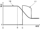
- FIG. 5 is a current waveform diagram in the process of interrupting the short-circuit current in the second test method.
- FIG. 6 is a voltage waveform diagram in the process of interrupting the short-circuit current in the second test method.
- the DC circuit breaker 1 is connected to the test device, the protective circuit breaker 3 and the auxiliary circuit breaker 8 are closed, the closing switch 4 and the start switch 11 are opened, and the short-circuit generator 2 is set at a predetermined voltage in advance. It is assumed that the voltage source capacitor 10 is in an excited state and is charged to a predetermined voltage by the charging device 9 in advance.
- the closing switch 4 is closed at time D, and an alternating current is supplied from the short-circuit generator 2 to the breaker 101 of the DC breaker 1.
- the magnitude of the alternating current is adjusted by the reactor 5 and is supplied to the interrupting unit 101 as an accident current 19.
- the voltage 18 of the voltage source capacitor 10 is kept constant. .
- the DC breaker 1 cuts off the current 19. That is, when the current 19 reaches a current corresponding to an accident current due to a system fault in the DC system, the current is cut by opening the cutoff unit 101 and cutting the current.
- a recovery voltage 21 having a frequency determined by the reactor 5, the resistor 6, and the capacitor 7 is applied to the DC breaker 1, and the surge absorber 102 absorbs the overvoltage, and as shown in FIG.
- a current supplied from the short-circuit generator 2 flows as a surge absorber current 20 in 102. While the surge absorber current 20 is flowing, the recovery voltage 21 gradually decreases as shown in FIG.
- the connection of the current source circuit B to the DC breaker 1 is continued.
- the start switch 11 is turned on, and the auxiliary circuit breaker 8 is opened to cut the current.
- a DC voltage equivalent to the voltage source capacitor voltage 22 stored in the voltage source capacitor 10 is applied to the DC circuit breaker 1.
- the timing of applying the voltage to the DC circuit breaker 1 using the voltage source circuit B is delayed until the recovery voltage after the current interruption corresponding to the accident current is applied, the recovery voltage of the DC circuit breaker 1 is Can be compensated.
- the application of the DC voltage from the voltage source circuit B is less than the voltage equivalent after the current interruption and the recovery voltage applied to the interrupting unit 101 of the DC circuit breaker 1 is equivalent to the DC system fault equivalent. It will be before. Thereby, it is possible to verify the withstand voltage performance of the DC breaker 1 after interruption of the fault current. As shown in FIG. 6, in the present embodiment, the recovery voltage 21 suddenly drops at the time F, because the energy accumulated in the reactor 5 is all released.
- the test method for the DC circuit breaker according to the present embodiment is a test method for the DC circuit breaker 1 for verifying the circuit breaker performance using a test apparatus including a current source circuit A and a voltage source circuit B. At least when an AC current is supplied to the DC circuit breaker 1 from the current source circuit A and the current becomes equivalent to an accident current due to a system fault in the DC system, the DC circuit breaker 1 interrupts the current, Previously, a voltage was applied to the DC circuit breaker 1 by connecting the voltage source circuit B to the DC circuit breaker 1, and a recovery voltage was applied from the voltage source circuit B simultaneously with the interruption.
- the current source circuit A supplies an AC current less than the accident current to the DC circuit breaker 1, and the voltage source circuit B is connected to the DC circuit breaker 1 before the DC circuit breaker 1 is shut off.
- the current from the voltage source circuit B is superimposed on the current of the current source circuit A to obtain a current corresponding to the accident current, and a voltage is applied to the DC circuit breaker 1.
- the voltage source circuit B is connected to the DC breaker 1 when the current is interrupted. Also, there is a possibility that a time difference will occur between the current interruption and the application of the recovery voltage after the interruption time.
- the voltage source circuit B is connected in advance and the voltage is applied before the current interruption, so that the time when the current corresponding to the accident current is reached by the current interruption and the voltage source circuit B
- the time points at which the recovery voltages are applied can be automatically aligned. Therefore, the recovery voltage can be applied without delay at the same time as the interruption.
- the current is supplied from the voltage source circuit B in a superimposed manner, the current supplied by the current source circuit A can be reduced accordingly. Therefore, as compared with the case where the voltage source circuit B is connected to the DC circuit breaker 1 simultaneously with the current interruption, it is not necessary to supply a large current as the short-circuit generator 2 used in the current source circuit A. As a result, there is an advantage that variations in equipment use and circuit design of the test apparatus can be increased.
- the voltage source circuit B has a voltage source capacitor 10 serving as a voltage source, and the connection of the voltage source circuit B to the DC circuit breaker 1 is immediately before the interruption when reaching the equivalent of the accident current.
- a predetermined recovery voltage can be applied more reliably when the current is interrupted. That is, when the voltage source is a capacitor, the voltage decreases because the battery is discharged as the voltage source circuit B is connected. Therefore, if the voltage source circuit B is connected to the DC circuit breaker 1 at a stage much earlier than the current interruption, there is a possibility that a predetermined recovery voltage for verifying the interruption performance cannot be applied at the time of the current interruption. Therefore, in order to avoid this, it is performed immediately before reaching the equivalent of the accident current, so that a predetermined recovery voltage can be applied more reliably when the current is interrupted.
- the overvoltage is absorbed by the surge absorber 102 provided in parallel with the DC circuit breaker 1. Thereby, it can suppress that overvoltage is added to the interruption
- the interruption test method for the DC circuit breaker 1 of the present embodiment is a DC circuit breaker test method for verifying the interruption performance using a test apparatus including a current source circuit A and a voltage source circuit B.
- the current corresponding to the fault current due to the system fault of the DC system is supplied to the DC circuit breaker 1 from the current source circuit A, the current is interrupted by the DC circuit breaker 1, and the recovery voltage from the current source circuit A is supplied to the DC circuit breaker 1. Is applied, while the connection of the current source circuit A to the DC circuit breaker 1 is continued and the recovery voltage is applied, a DC voltage is applied from the voltage source circuit B to the DC circuit breaker 1.
- the DC voltage is applied from the voltage source circuit B while the recovery voltage is being applied, the voltage is applied from the voltage source circuit B to the DC circuit breaker 1 at least until the current is interrupted. Not. Therefore, the voltage of the voltage source circuit B can be maintained, and it can be prevented that the withstand voltage performance after the interruption cannot be verified because the recovery voltage becomes less than the voltage corresponding to the accident of the DC system after the current interruption. In other words, it is possible to compensate for the recovery voltage of the interrupting unit 101 of the DC circuit breaker 1 after the DC circuit breaker 1 completes the interruption of the accident current from the current source circuit A, and to verify the withstand voltage performance after the current interruption. Can do.
- the overvoltage is absorbed by the surge absorber 102 provided in parallel with the breaker 101 of the DC breaker 1. Thereby, it can suppress that overvoltage is added to the interruption
- the above-described instantaneous test method and the test method after the interruption may be realized by providing a control unit without depending on the operator.
- the control unit is a computer having a recording medium in which a program for sequence management is stored.
- the control unit is connected to or disconnected from each device of each circuit A and B at a predetermined timing.
- a command may be output.
- the method for verifying the interrupting performance of the DC circuit breaker with the test apparatus used for the AC circuit breaker synthesis test method has been described.
- a test apparatus equivalent to the synthesis test method may be used. .
- the surge absorber 102 is provided inside the DC circuit breaker 1, it may be provided outside the DC circuit breaker 1 as long as it is provided in parallel with the circuit breaker 101.
Abstract
Provided is a testing method for a DC circuit breaker, in which the circuit breaking ability of a DC circuit breaker is verified with a testing device that is used in synthetic testing for an AC circuit breaker. A testing method according to the present invention is a testing method for a DC circuit breaker 1, in which the circuit breaking ability of the DC circuit breaker 1 is verified by using a testing device including a current source circuit A and a voltage source circuit B, wherein at least an AC current from the current source circuit A is supplied to the DC circuit breaker 1, the current is shut off by the DC circuit breaker 1 when the level of the current has reached a level corresponding to a fault current due to a DC grid fault, the voltage source circuit B is connected to the DC circuit breaker 1 before the shut-off to apply a voltage to the DC circuit breaker 1, and a recovery voltage is applied from the voltage source circuit B simultaneously with the shut-off.
Description
本発明の実施形態は、直流遮断器の遮断性能を検証するための試験方法に関する。
Embodiment of this invention is related with the test method for verifying the interruption | blocking performance of a DC circuit breaker.
交流電力系統の落雷等による短絡事故からの系統保護を行うため、大容量の交流遮断器が用いられている。この交流遮断器の遮断試験法には、合成試験法と呼ばれる試験法が知られている(例えば、非特許文献1参照。)。この合成試験法は、試験対象となる交流遮断器に対して、事故電流相当の短絡電流を供給する電流源回路と、高周波電流を供給し回復電圧を印加するための電圧源回路とが、それぞれ並列に接続される試験装置を用いて行われる。
A large-capacity AC circuit breaker is used to protect the system from short-circuit accidents caused by lightning strikes in the AC power system. A test method called a synthetic test method is known as an AC circuit breaker test method (for example, see Non-Patent Document 1). In this synthetic test method, a current source circuit for supplying a short-circuit current corresponding to an accident current and a voltage source circuit for supplying a high-frequency current and applying a recovery voltage to the AC circuit breaker to be tested are respectively provided. This is performed using a test apparatus connected in parallel.
具体的には、次の(1)~(4)の手順で交流遮断器の遮断試験を行う。
(1)電流源回路から事故電流相当の交流の短絡電流を交流遮断器に供給する。
(2)当該短絡電流の最終零値直前で電圧源回路から高周波電流を供給して、電流源回路及び電圧源回路の2回路から重畳電流を交流遮断器に流す。
(3)電流源回路を、短絡電流が最終零値となる時点で交流遮断器から遮断する。
(4)その後、高周波電流を交流遮断器により遮断し、当該交流遮断器の端子間に回復電圧を生じさせる。 Specifically, the AC circuit breaker breaking test is performed according to the following procedures (1) to (4).
(1) Supply an AC short circuit current corresponding to an accident current from the current source circuit to the AC circuit breaker.
(2) A high-frequency current is supplied from the voltage source circuit immediately before the final zero value of the short-circuit current, and a superimposed current is supplied to the AC circuit breaker from the two circuits of the current source circuit and the voltage source circuit.
(3) The current source circuit is disconnected from the AC circuit breaker when the short-circuit current reaches the final zero value.
(4) Thereafter, the high-frequency current is interrupted by the AC circuit breaker, and a recovery voltage is generated between the terminals of the AC circuit breaker.
ところで、直流系統の短絡事故から系統保護を行うため、直流遮断器が用いられている。直流遮断器は、短絡等による事故電流を遮断する。このような系統保護を確実に行うため、直流遮断器には、用いられる直流系統に応じて所定の遮断性能が要求される。
By the way, in order to protect the system from a short circuit accident of the DC system, a DC circuit breaker is used. The DC breaker cuts off the accident current due to short circuit. In order to reliably perform such system protection, the DC circuit breaker is required to have a predetermined breaking performance depending on the DC system used.
直流遮断器の遮断試験方法として、交流の短絡発電機からの短絡事故電流を整流器にて直流電流に整流させて、直流系統事故を模擬した短絡時の事故電流を供給する方法がある。
There is a method of supplying a fault current at the time of a short circuit that simulates a DC system fault by rectifying a short-circuit fault current from an AC short-circuit generator into a DC current using a rectifier as a DC circuit breaker test method.
しかし、近年、直流遮断器の大容量化が進んでいる。そのため、従来の整流器を用いた試験方法では、大容量の整流器を設ける必要があり、試験設備の大型化や設備導入に莫大な投資を要するという問題がある。さらに、大容量の整流器を用いた試験方法では試験効率に問題がある。そのため、従来の整流器を用いた試験方法を採用することは困難であり、別の試験方法が求められる。
However, in recent years, the capacity of DC circuit breakers has been increasing. Therefore, in the conventional test method using a rectifier, it is necessary to provide a large-capacity rectifier, and there is a problem that enormous investment is required for increasing the size of test equipment and introducing equipment. Further, the test method using a large capacity rectifier has a problem in test efficiency. Therefore, it is difficult to adopt a test method using a conventional rectifier, and another test method is required.
この点につき、交流遮断器の合成試験法に用いる試験装置を、直流遮断器の遮断性能試験に用いることが考えられる。しかし、この場合には、上記のような手順で遮断性能試験をすることはできない。すなわち、上記の合成試験法では、直流遮断器に、直流系統の事故に相当する電流、電圧の両方を与えることができず、直流遮断器の遮断性能を検証することはできない。
In this regard, it is conceivable to use a test apparatus used in the AC circuit breaker synthesis test method for the DC circuit breaker breaking performance test. However, in this case, the interruption performance test cannot be performed according to the above procedure. That is, in the above synthetic test method, it is impossible to give both a current and a voltage corresponding to an accident of the DC system to the DC breaker, and it is impossible to verify the breaking performance of the DC breaker.
本発明の実施形態に係る直流遮断器の試験方法は、上記のような課題を解決するためになされたものであり、直流遮断器の遮断性能を検証する直流遮断器の試験方法を提供することを目的とする。
A DC circuit breaker test method according to an embodiment of the present invention has been made to solve the above-described problems, and provides a DC circuit breaker test method for verifying the circuit breaker performance of the DC circuit breaker. With the goal.
上記の目的を達成するために、本実施形態の直流遮断器の試験方法は、電流源回路と電圧源回路とを備える試験装置を用いて遮断性能を検証するための直流遮断器の試験方法であって、前記直流遮断器に、少なくとも前記電流源回路から交流の電流を供給し、前記電流が直流系統の系統事故による事故電流相当となった時点で、前記直流遮断器により前記電流を遮断し、前記遮断以前に、前記電圧源回路を前記直流遮断器に接続することにより前記直流遮断器に電圧を印加し、前記遮断と同時に前記電圧源回路から回復電圧を印加することを特徴とする。
In order to achieve the above object, the DC circuit breaker test method of the present embodiment is a DC circuit breaker test method for verifying the circuit breaker performance using a test apparatus including a current source circuit and a voltage source circuit. And supplying at least an AC current from the current source circuit to the DC circuit breaker, and when the current becomes equivalent to an accident current due to a system fault in a DC system, the current is interrupted by the DC circuit breaker. Before the interruption, the voltage source circuit is connected to the DC circuit breaker to apply a voltage to the DC circuit breaker, and simultaneously with the interruption, a recovery voltage is applied from the voltage source circuit.
また、本実施形態の直流遮断器の試験方法は、電流源回路と電圧源回路とを備える試験装置を用いて遮断性能を検証するための直流遮断器の試験方法であって、前記直流遮断器に前記電流源回路から、直流系統の系統事故による事故電流相当の電流を供給し、前記直流遮断器により当該電流を遮断し、前記直流遮断器に前記電流源回路から回復電圧が印加され、前記電流源回路の前記直流遮断器への接続が継続されて前記回復電圧が印加されている間に、前記電圧源回路から前記直流遮断器に直流電圧を印加することを特徴とする。
The DC circuit breaker test method of the present embodiment is a DC circuit breaker test method for verifying the circuit breaker performance using a test apparatus including a current source circuit and a voltage source circuit, and the DC circuit breaker A current corresponding to an accident current due to a system fault in a DC system is supplied from the current source circuit, the current is interrupted by the DC circuit breaker, and a recovery voltage is applied to the DC circuit breaker from the current source circuit, A DC voltage is applied from the voltage source circuit to the DC circuit breaker while the connection of the current source circuit to the DC circuit breaker is continued and the recovery voltage is applied.
[1.第1の実施形態]
[1-1.全体構成]
以下では、図1~図3を参照しつつ、本実施形態に係る直流遮断器の試験方法とその試験方法に用いる試験装置について説明する。図1は、本実施形態に係る直流遮断器の試験装置の構成を示す回路図である。 [1. First Embodiment]
[1-1. overall structure]
Hereinafter, a test method for a DC circuit breaker according to the present embodiment and a test apparatus used for the test method will be described with reference to FIGS. FIG. 1 is a circuit diagram showing the configuration of a test apparatus for a DC circuit breaker according to this embodiment.
直流遮断器の試験装置は、試験対象となる直流遮断器1の直流電流の遮断性能を試験する装置である。本実施形態に係る直流遮断器の試験装置は、従来の交流遮断器の遮断試験に用いられる合成試験回路と同様の構造を有する。すなわち、本実施形態では、合成試験回路に設置される交流遮断器を直流遮断器に置き換えて当該合成試験回路を使用して、直流遮断器の遮断性能を検証する。具体的には、本試験装置は、直流系統の故障発生を模擬するため、後述する2つの電源回路を備える。直流系統としては、例えば、長距離送電や電力会社間などの直流送電系統や、ビルや大型商業施設などの直流配電、電気鉄道等の直流系統などが挙げられる。
The DC circuit breaker test device is a device for testing the direct current circuit breaker performance of the DC circuit breaker 1 to be tested. The DC circuit breaker testing apparatus according to the present embodiment has the same structure as a synthetic test circuit used for a conventional AC circuit breaker break test. That is, in this embodiment, the AC circuit breaker installed in the composite test circuit is replaced with a DC circuit breaker, and the composite test circuit is used to verify the breaking performance of the DC circuit breaker. Specifically, this test apparatus includes two power supply circuits to be described later in order to simulate the occurrence of a fault in the DC system. Examples of the DC system include DC transmission systems such as long-distance transmission and between power companies, DC distribution such as buildings and large commercial facilities, and DC systems such as electric railways.
直流遮断器1は、直流遮断器1内を流れる直流電流を遮断する遮断器である。直流遮断器1は、遮断部101と、エネルギー吸収部102とを備える。遮断部101とエネルギー吸収部102とは並列に設けられる。
The DC circuit breaker 1 is a circuit breaker that interrupts a direct current flowing through the DC circuit breaker 1. The DC circuit breaker 1 includes a breaker 101 and an energy absorber 102. The blocking unit 101 and the energy absorbing unit 102 are provided in parallel.
遮断器101は、回路を流れる電流の遮断/投入を行うスイッチである。遮断部101としては、半導体を用いた半導体遮断部を含み構成される。この遮断部101には、半導体遮断部の他、機械的に遮断/投入を行う機械式の遮断部を含んでいても良い。
The circuit breaker 101 is a switch for cutting off / closing current flowing through the circuit. The blocking unit 101 includes a semiconductor blocking unit using a semiconductor. The shut-off unit 101 may include a mechanical shut-off unit that mechanically shuts off / in addition to the semiconductor shut-off unit.
エネルギー吸収部102は、所謂サージアブソーバ(以下、サージアブソーバ102ともいう)である。サージアブソーバ102は、サージアブソーバ102に印加される過渡的な高電圧のエネルギーの吸収を行う。サージアブソーバ102は、遮断部101遮断後の電圧の大きさを制限する。
The energy absorbing unit 102 is a so-called surge absorber (hereinafter also referred to as a surge absorber 102). The surge absorber 102 absorbs transient high voltage energy applied to the surge absorber 102. The surge absorber 102 limits the magnitude of the voltage after the interruption unit 101 is interrupted.
直流遮断器1には、2つの異なる電源回路が並列に接続される。すなわち、本実施形態に係る試験装置は、直流遮断器1に対し、交流の電流を供給する電流源回路Aと、直流遮断器1に対し、回復電圧を印加する電圧源回路Bとを備え、これらの回路A、Bが直流遮断器1に対して並列に接続される。
The DC circuit breaker 1 is connected with two different power supply circuits in parallel. That is, the test apparatus according to this embodiment includes a current source circuit A that supplies an alternating current to the DC circuit breaker 1 and a voltage source circuit B that applies a recovery voltage to the DC circuit breaker 1. These circuits A and B are connected in parallel to the DC circuit breaker 1.
[1-2.詳細構成]
(電流源回路)
電流源回路Aは、直流遮断器1に対して、交流の電流を供給する。電流源回路Aは、短絡発電機2、保護遮断器3、投入スイッチ4、リアクトル5、抵抗6、コンデンサ7、及び補助遮断器8を含み構成される。 [1-2. Detailed configuration]
(Current source circuit)
The current source circuit A supplies an AC current to the DC circuit breaker 1. The current source circuit A includes a short-circuit generator 2, a protective circuit breaker 3, a closing switch 4, a reactor 5, a resistor 6, a capacitor 7, and an auxiliary circuit breaker 8.
(電流源回路)
電流源回路Aは、直流遮断器1に対して、交流の電流を供給する。電流源回路Aは、短絡発電機2、保護遮断器3、投入スイッチ4、リアクトル5、抵抗6、コンデンサ7、及び補助遮断器8を含み構成される。 [1-2. Detailed configuration]
(Current source circuit)
The current source circuit A supplies an AC current to the DC circuit breaker 1. The current source circuit A includes a short-
短絡発電機2は、短絡電流を発生させる発電機である。短絡発電機2から発生される短絡電流は交流の電流である。短絡発電機2で発生した短絡電流は、リアクトル5を介して直流遮断器1に対して出力される。
The short-circuit generator 2 is a generator that generates a short-circuit current. The short circuit current generated from the short circuit generator 2 is an alternating current. The short-circuit current generated in the short-circuit generator 2 is output to the DC circuit breaker 1 through the reactor 5.
短絡発電機2と直流遮断器1との間には、保護遮断器3と投入スイッチ4とが設けられている。投入スイッチ4は、短絡発電機2を試験回路に接続するための開閉器であり、直流遮断器1に対する短絡発電機2の接続と遮断を切り替える。保護遮断器3は、電流源回路Aを流れる交流の短絡電流の遮断を行う遮断器である。保護遮断器3は、この交流の短絡電流の電流零点で遮断を行う。
A protective circuit breaker 3 and a closing switch 4 are provided between the short-circuit generator 2 and the DC circuit breaker 1. The input switch 4 is a switch for connecting the short-circuit generator 2 to the test circuit, and switches connection and disconnection of the short-circuit generator 2 to the DC circuit breaker 1. The protective circuit breaker 3 is a circuit breaker that blocks AC short-circuit current flowing through the current source circuit A. The protective circuit breaker 3 cuts off at the current zero point of this AC short-circuit current.
さらに電流源回路Aには、補助遮断器8と、サージ吸収部41とが設けられている。補助遮断器8は、短絡発電機2と接続されており、試験対象である直流遮断器1と短絡発電機2との接続と遮断を切り替える。補助遮断器8は、例えば機械式の遮断器である。補助遮断器8は、電流源回路Aにおいて、各機器のうち最も直流遮断器1側に設けられている。補助遮断器8が投入状態にあるときは、直流遮断器1に短絡発電機2から電流を供給可能であり、補助遮断器8が遮断状態にあるときは、電流源回路Aが直流遮断器1から切り離されており、短絡発電機2から電流は直流遮断器1に供給されない。
Furthermore, the current source circuit A is provided with an auxiliary circuit breaker 8 and a surge absorber 41. The auxiliary circuit breaker 8 is connected to the short circuit generator 2 and switches between connection and disconnection between the DC circuit breaker 1 and the short circuit generator 2 to be tested. The auxiliary circuit breaker 8 is, for example, a mechanical circuit breaker. The auxiliary circuit breaker 8 is provided closest to the DC circuit breaker 1 among the devices in the current source circuit A. When the auxiliary circuit breaker 8 is in the on state, current can be supplied from the short-circuit generator 2 to the DC circuit breaker 1, and when the auxiliary circuit breaker 8 is in the interruption state, the current source circuit A is connected to the DC circuit breaker 1. The current is not supplied to the DC breaker 1 from the short-circuit generator 2.
サージ吸収部41は、補助遮断器8と接続されており、補助遮断器8で遮断された際に発生するサージを吸収する。サージ吸収部41は、前述の抵抗6とコンデンサ7とが直列接続されてなり、コンデンサ7が抵抗6を介してサージを吸収し、補助遮断器8による遮断をしやすくする。
The surge absorber 41 is connected to the auxiliary circuit breaker 8 and absorbs a surge generated when the auxiliary circuit breaker 8 is interrupted. The surge absorber 41 is formed by connecting the resistor 6 and the capacitor 7 in series. The capacitor 7 absorbs the surge through the resistor 6 and facilitates the interruption by the auxiliary circuit breaker 8.
(電圧源回路)
電圧源回路Bは、直流遮断器1に対して回復電圧を印加する。電圧源回路Bは、電圧源コンデンサ10、充電装置9、始動スイッチ11、リアクトル12、抵抗13及びコンデンサ14を含み構成される。 (Voltage source circuit)
The voltage source circuit B applies a recovery voltage to the DC circuit breaker 1. The voltage source circuit B includes avoltage source capacitor 10, a charging device 9, a start switch 11, a reactor 12, a resistor 13, and a capacitor 14.
電圧源回路Bは、直流遮断器1に対して回復電圧を印加する。電圧源回路Bは、電圧源コンデンサ10、充電装置9、始動スイッチ11、リアクトル12、抵抗13及びコンデンサ14を含み構成される。 (Voltage source circuit)
The voltage source circuit B applies a recovery voltage to the DC circuit breaker 1. The voltage source circuit B includes a
電圧源コンデンサ10は、電圧源回路Bの電圧源となる直流コンデンサである。電圧源コンデンサ10は、始動スイッチ11が投入状態である場合に、リアクトル12を介して直流遮断器1に対して回復電圧を印加する。電圧源コンデンサ10は、直流遮断器1が設けられる直流系統事故時の短絡電流の一部を供給する容量を有する。また、回復電圧は、他のコンデンサを過渡回復電圧の調整用として併用しても良い。
The voltage source capacitor 10 is a DC capacitor serving as a voltage source for the voltage source circuit B. The voltage source capacitor 10 applies a recovery voltage to the DC circuit breaker 1 via the reactor 12 when the start switch 11 is in the on state. The voltage source capacitor 10 has a capacity for supplying a part of a short-circuit current at the time of a DC system fault in which the DC circuit breaker 1 is provided. The recovery voltage may be used in combination with another capacitor for adjusting the transient recovery voltage.
充電装置9は、電圧源コンデンサ10と並列接続され、電圧源コンデンサ10を充電する装置である。始動スイッチ11は、電圧源コンデンサ10からの電圧印加のオンとオフを切り替える機器である。
The charging device 9 is a device that is connected in parallel with the voltage source capacitor 10 and charges the voltage source capacitor 10. The start switch 11 is a device that switches on / off of voltage application from the voltage source capacitor 10.
電圧源回路Bは、電圧源コンデンサ10を直流電圧源として、過渡振動回路(LCR回路)を備える。すなわち、電圧源コンデンサ10に対して、リアクトル12、抵抗13及びコンデンサ14が直列に接続されており、過渡振動回路を構成する。この過渡振動回路は、過渡現象を発生させて直流遮断器1に印加する電圧を調整する。このため、電圧源回路Bが直流遮断器1に印加する回復電圧は、高周波電圧である。
The voltage source circuit B includes a transient oscillation circuit (LCR circuit) using the voltage source capacitor 10 as a DC voltage source. That is, the reactor 12, the resistor 13, and the capacitor 14 are connected in series to the voltage source capacitor 10, and constitute a transient vibration circuit. This transient vibration circuit adjusts the voltage applied to the DC circuit breaker 1 by generating a transient phenomenon. For this reason, the recovery voltage applied to the DC circuit breaker 1 by the voltage source circuit B is a high-frequency voltage.
コンデンサ14は、電圧源コンデンサ10が供給する電圧を調整する電圧調整用コンデンサである。ここでは、コンデンサ14は、電圧源コンデンサ10と併用して直流系統事故時に直流遮断器1に印加される電圧を調整するコンデンサである。
The capacitor 14 is a voltage adjusting capacitor that adjusts the voltage supplied by the voltage source capacitor 10. Here, the capacitor 14 is a capacitor that is used in combination with the voltage source capacitor 10 to adjust the voltage applied to the DC circuit breaker 1 when a DC system fault occurs.
[1-3.試験方法]
本実施形態の試験方法は、半導体遮断器を含む直流遮断器の、直流系統の短絡事故電流の遮断性能を検証するための方法であり、(1)遮断瞬時の遮断性能を検証するための第1の試験方法と、(2)遮断後の遮断性能を検証するための第2の試験方法を分けて行う。遮断瞬時の遮断性能の試験方法を図2及び図3を用いて説明する。図2は、第1の試験方法の短絡電流遮断を行う過程における電流波形図である。図3は、第1の試験方法の短絡電流遮断を行う過程における電圧波形図である。 [1-3. Test method]
The test method of the present embodiment is a method for verifying the short circuit fault current interrupting performance of a DC system of a DC circuit breaker including a semiconductor circuit breaker. The test method 1 and (2) the second test method for verifying the interruption performance after interruption are performed separately. A method for testing the instantaneous interruption performance will be described with reference to FIGS. FIG. 2 is a current waveform diagram in the process of short-circuit current interruption in the first test method. FIG. 3 is a voltage waveform diagram in the process of performing the short-circuit current interruption in the first test method.
(1)遮断瞬時の遮断性能を検証するための第1の試験方法
試験開始時には、直流遮断器1が試験装置に接続され、保護遮断器3及び補助遮断器8は閉路状態、投入スイッチ4及び始動スイッチ11は開路状態、短絡発電機2は予め所定の電圧での励磁状態、電圧源コンデンサ10は充電装置9によって予め所定の電圧まで充電された状態にあるとする。 (1) First test method for verifying the breaking performance at the moment of breaking At the start of the test, the DC breaker 1 is connected to the test device, theprotective breaker 3 and the auxiliary breaker 8 are closed, the closing switch 4 and It is assumed that the start switch 11 is in an open circuit state, the short-circuit generator 2 is in an excited state at a predetermined voltage, and the voltage source capacitor 10 is in a state charged to a predetermined voltage by the charging device 9 in advance.
試験開始時には、直流遮断器1が試験装置に接続され、保護遮断器3及び補助遮断器8は閉路状態、投入スイッチ4及び始動スイッチ11は開路状態、短絡発電機2は予め所定の電圧での励磁状態、電圧源コンデンサ10は充電装置9によって予め所定の電圧まで充電された状態にあるとする。 (1) First test method for verifying the breaking performance at the moment of breaking At the start of the test, the DC breaker 1 is connected to the test device, the
まず、図3に示すように、時刻Aにおいて投入スイッチ4を閉路し、短絡発電機2から直流遮断器1の遮断部101に交流電流を供給する。この交流電流は、時刻Aにおいては0Aであり、その後上昇する。この交流電流は、リアクトル5によりその大きさが調整されている。
First, as shown in FIG. 3, at time A, the closing switch 4 is closed, and an alternating current is supplied from the short-circuit generator 2 to the breaking unit 101 of the DC breaker 1. This alternating current is 0 A at time A and then increases. The magnitude of this alternating current is adjusted by the reactor 5.
次に、時刻Bにおいて、始動スイッチ11を投入する。この投入タイミングは、短絡発電機2により供給される交流電流が波高値となる前とする。すなわち、交流電流の1/4周期までとすれば良い。本実施形態では、始動スイッチ11が投入されるまでに遮断部101に供給される電流は、直流系統の系統事故による事故電流未満の電流である。
Next, at time B, the start switch 11 is turned on. This charging timing is set before the alternating current supplied by the short-circuit generator 2 reaches a peak value. That is, it may be up to ¼ period of alternating current. In the present embodiment, the current supplied to the interrupting unit 101 before the start switch 11 is turned on is less than the accident current due to the DC system fault.
この始動スイッチ11の投入タイミングは、直流遮断器1の遮断部101による電流遮断以前に行えば良く、当該電流遮断と同時又はその直前を含む。本実施形態では、始動スイッチ11の投入タイミングは、当該電流遮断よりも前である。
The start-up switch 11 may be turned on before the current is interrupted by the interrupting unit 101 of the DC circuit breaker 1 and includes the same time as or immediately before the current interrupting. In this embodiment, the start timing of the start switch 11 is before the current interruption.
始動スイッチ11を投入すると、電圧源コンデンサ10とリアクトル12によって決まる周波数の交流電流が遮断部101に供給される。すなわち、始動スイッチ11の投入により電圧源回路Bが直流遮断器に接続され、短絡発電機2からの交流電流に電圧源回路Bからの交流電流が重畳される。この重畳された電流15は、図2に示すように、遮断部101に供給されて上昇していく。また、時刻Bで始動スイッチ11が投入されたことで、電圧源回路Bが直流遮断器1に接続され、これによって直流遮断器1に電圧が印加される。電圧源回路Bの主電源が電圧源コンデンサ10であるため、図3に示すように、電圧源コンデンサ10の電圧はその放電により下降していく。
When the start switch 11 is turned on, an alternating current having a frequency determined by the voltage source capacitor 10 and the reactor 12 is supplied to the cutoff unit 101. That is, when the start switch 11 is turned on, the voltage source circuit B is connected to the DC circuit breaker, and the AC current from the voltage source circuit B is superimposed on the AC current from the short-circuit generator 2. As shown in FIG. 2, the superimposed current 15 is supplied to the blocking unit 101 and rises. Further, when the start switch 11 is turned on at time B, the voltage source circuit B is connected to the DC circuit breaker 1, whereby a voltage is applied to the DC circuit breaker 1. Since the main power supply of the voltage source circuit B is the voltage source capacitor 10, as shown in FIG. 3, the voltage of the voltage source capacitor 10 decreases due to the discharge.
重畳された電流15となった後、当該電流15が事故電流相当以上となる時刻Cで、遮断部101及び補助遮断器8を開路して電流裁断し、電流15を遮断する。本実施形態では、事故電流相当の電流に達した時点で電流15を遮断する。
After the superimposed current 15 is reached, at time C when the current 15 becomes equal to or greater than the accident current, the breaker 101 and the auxiliary breaker 8 are opened to cut the current, and the current 15 is cut off. In the present embodiment, the current 15 is interrupted when the current corresponding to the accident current is reached.
この遮断により、直流遮断器1の遮断部101間には、電圧源回路Bからの過渡回復電圧17が印加されるとともに、サージアブソーバ102が過電圧を吸収し、図2に示すように、電圧源コンデンサ10から供給される電流はサージアブソーバ電流16となって当該サージアブソーバ102に流れる。時刻Cにおける電圧源コンデンサ10の電圧は、直流系統の事故による電流遮断時に直流遮断器1に印加される電圧相当の電圧又はそれ以上である。
As a result of this interruption, the transient recovery voltage 17 from the voltage source circuit B is applied between the interruption parts 101 of the DC breaker 1, and the surge absorber 102 absorbs the overvoltage, and as shown in FIG. The current supplied from the capacitor 10 becomes a surge absorber current 16 and flows to the surge absorber 102. The voltage of the voltage source capacitor 10 at time C is equal to or higher than the voltage applied to the DC circuit breaker 1 when the current is interrupted due to an accident in the DC system.
以上のように、直流遮断器1に事故電流相当未満の電流を供給する段階であって、電流遮断よりも前に、電圧源回路Bを直流遮断器1に接続することにより、直流遮断器1に対し、電流供給と電圧印加の両方を行うようにした。これにより、電流遮断時において、直流遮断器1に、直流系統の事故による事故電流相当の電流と、当該事故に伴い印加される相当の電圧である所定の回復電圧とを与えることができるので、直流遮断器1の遮断時における遮断性能を検証することができる。
As described above, by connecting the voltage source circuit B to the DC circuit breaker 1 before supplying the current less than the accident current to the DC circuit breaker 1, the DC circuit breaker 1 On the other hand, both current supply and voltage application were performed. Thereby, at the time of current interruption, it is possible to give the DC breaker 1 a current corresponding to an accident current due to an accident in the DC system and a predetermined recovery voltage which is a substantial voltage applied in association with the accident. The breaking performance when the DC breaker 1 is broken can be verified.
[第1の試験方法の変形例]
(1)上記の第1の試験方法では、始動スイッチ11の投入タイミングを直流遮断器1による電流遮断よりも前とし、当該遮断よりも前に電圧源回路Bを直流遮断器1に接続するようにしたが、電流遮断時に、事故電流相当の電流と、事故電流遮断に伴う電圧相当の所定の回復電圧とが直流遮断器1に与えられれば良く、電圧源回路Bの直流遮断器1への接続タイミングを当該遮断と同時としても良い。このようにしても電流遮断時に、事故電流相当の電流と、事故電流遮断に伴う電圧相当の所定の回復電圧を与えることができる。 [Modification of First Test Method]
(1) In the first test method described above, thestart switch 11 is turned on before the current interruption by the DC breaker 1, and the voltage source circuit B is connected to the DC breaker 1 before the interruption. However, when the current is interrupted, a current corresponding to the accident current and a predetermined recovery voltage corresponding to the voltage associated with the accident current interruption may be supplied to the DC circuit breaker 1. The connection timing may be simultaneous with the interruption. Even in this way, when the current is interrupted, a current corresponding to the accident current and a predetermined recovery voltage corresponding to the voltage associated with the accident current interruption can be provided.
(1)上記の第1の試験方法では、始動スイッチ11の投入タイミングを直流遮断器1による電流遮断よりも前とし、当該遮断よりも前に電圧源回路Bを直流遮断器1に接続するようにしたが、電流遮断時に、事故電流相当の電流と、事故電流遮断に伴う電圧相当の所定の回復電圧とが直流遮断器1に与えられれば良く、電圧源回路Bの直流遮断器1への接続タイミングを当該遮断と同時としても良い。このようにしても電流遮断時に、事故電流相当の電流と、事故電流遮断に伴う電圧相当の所定の回復電圧を与えることができる。 [Modification of First Test Method]
(1) In the first test method described above, the
(2)上記の第1の試験方法では、直流遮断器1への事故電流相当の電流を、2つの電流源回路A、電圧源回路Bを重畳させることによって供給するようにしたが、電流源回路Aのみで供給するようにしても良い。この場合、電圧源回路Bの直流遮断器1への接続は、電流遮断と同時に行う。
(2) In the first test method described above, the current corresponding to the fault current to the DC circuit breaker 1 is supplied by superimposing the two current source circuits A and the voltage source circuit B. It is also possible to supply only by the circuit A. In this case, the connection of the voltage source circuit B to the DC breaker 1 is performed simultaneously with the current interruption.
(3)上記の第1の試験方法では、始動スイッチ11の投入タイミングを、単に、直流遮断器1による電流遮断よりも前としたが、本実施形態のように電圧源回路Bの電圧源がコンデンサで構成される場合、直流遮断器1による電流遮断直前とすると良い。すなわち、このような場合、図3に示すように、電圧源回路Bの電圧はコンデンサの放電により低下していく。そのため、電流遮断よりかなり早い段階で始動スイッチ11を投入した場合には、電流遮断時に所定の回復電圧が印加できない虞がある。そのため、始動スイッチ11の投入、すなわち電圧源回路Bの直流遮断器1の接続は、電流遮断直前とする。ここにいう電流遮断直前とは、電圧源回路Bにより、電流遮断時において、事故電流遮断に伴う電圧相当の所定の回復電圧が直流遮断器1に印加できるタイミングをいう。
(3) In the first test method described above, the start timing of the start switch 11 is simply set before the current interruption by the DC circuit breaker 1, but the voltage source of the voltage source circuit B is the same as in this embodiment. In the case of a capacitor, it may be set immediately before the current interruption by the DC breaker 1. That is, in such a case, as shown in FIG. 3, the voltage of the voltage source circuit B decreases due to the discharge of the capacitor. Therefore, when the start switch 11 is turned on at a stage much earlier than the current interruption, there is a possibility that a predetermined recovery voltage cannot be applied when the current is interrupted. For this reason, the start switch 11 is turned on, that is, the connection of the DC circuit breaker 1 of the voltage source circuit B is immediately before the current interruption. The term “immediately before current interruption” refers to the timing at which the voltage source circuit B can apply a predetermined recovery voltage corresponding to the voltage associated with the accident current interruption to the DC breaker 1 when the current is interrupted.
(2)遮断後の遮断性能を検証するための第2の試験方法
次に、第2の試験方法、すなわち事故電流相当の電流遮断後における直流遮断器1の遮断性能を検証するための試験方法について説明する。図4は、図1に示した試験装置のうち、電圧源回路Bのリアクトル12、コンデンサ14を除いた試験装置の回路図である。第2の試験方法では、当該試験装置を用いる。電圧源回路Bは、リアクトル12、コンデンサ14を除いているため、直流遮断器1に印加する電圧は直流電圧である。図5は、第2の試験方法の短絡電流遮断を行う過程における電流波形図である。図6は、第2の試験方法の短絡電流遮断を行う過程における電圧波形図である。 (2) Second test method for verifying the breaking performance after breaking Next, the second test method, ie, the testing method for validating the breaking performance of the DC breaker 1 after breaking the current corresponding to the accident current Will be described. FIG. 4 is a circuit diagram of the test apparatus excluding thereactor 12 and the capacitor 14 of the voltage source circuit B from the test apparatus shown in FIG. In the second test method, the test apparatus is used. Since the voltage source circuit B excludes the reactor 12 and the capacitor 14, the voltage applied to the DC circuit breaker 1 is a DC voltage. FIG. 5 is a current waveform diagram in the process of interrupting the short-circuit current in the second test method. FIG. 6 is a voltage waveform diagram in the process of interrupting the short-circuit current in the second test method.
次に、第2の試験方法、すなわち事故電流相当の電流遮断後における直流遮断器1の遮断性能を検証するための試験方法について説明する。図4は、図1に示した試験装置のうち、電圧源回路Bのリアクトル12、コンデンサ14を除いた試験装置の回路図である。第2の試験方法では、当該試験装置を用いる。電圧源回路Bは、リアクトル12、コンデンサ14を除いているため、直流遮断器1に印加する電圧は直流電圧である。図5は、第2の試験方法の短絡電流遮断を行う過程における電流波形図である。図6は、第2の試験方法の短絡電流遮断を行う過程における電圧波形図である。 (2) Second test method for verifying the breaking performance after breaking Next, the second test method, ie, the testing method for validating the breaking performance of the DC breaker 1 after breaking the current corresponding to the accident current Will be described. FIG. 4 is a circuit diagram of the test apparatus excluding the
試験開始時には、直流遮断器1が試験装置に接続され、保護遮断器3及び補助遮断器8は閉路状態、投入スイッチ4及び始動スイッチ11は開路状態、短絡発電機2は予め所定の電圧での励磁状態、電圧源コンデンサ10は充電装置9によって予め所定の電圧まで充電された状態にあるとする。
At the start of the test, the DC circuit breaker 1 is connected to the test device, the protective circuit breaker 3 and the auxiliary circuit breaker 8 are closed, the closing switch 4 and the start switch 11 are opened, and the short-circuit generator 2 is set at a predetermined voltage in advance. It is assumed that the voltage source capacitor 10 is in an excited state and is charged to a predetermined voltage by the charging device 9 in advance.
まず、図5に示すように、時刻Dにおいて投入スイッチ4を閉路し、短絡発電機2から直流遮断器1の遮断部101に交流電流を供給する。この交流電流は、リアクトル5によりその大きさが調整されており、事故電流19として遮断部101に供給される。なお、図6に示すように、投入スイッチ4を閉路にしても、電圧源回路Bは、直流遮断器1に接続されていないので、電圧源コンデンサ10の電圧18は一定に保たれたままである。
First, as shown in FIG. 5, the closing switch 4 is closed at time D, and an alternating current is supplied from the short-circuit generator 2 to the breaker 101 of the DC breaker 1. The magnitude of the alternating current is adjusted by the reactor 5 and is supplied to the interrupting unit 101 as an accident current 19. As shown in FIG. 6, even when the closing switch 4 is closed, since the voltage source circuit B is not connected to the DC circuit breaker 1, the voltage 18 of the voltage source capacitor 10 is kept constant. .
次に、図5、6に示す時刻Eにおいて、直流遮断器1が電流19を遮断する。すなわち、電流19が直流系統の系統事故による事故電流相当の電流に達した時点で遮断部101を開路にして電流裁断し、電流19を遮断する。
Next, at time E shown in FIGS. 5 and 6, the DC breaker 1 cuts off the current 19. That is, when the current 19 reaches a current corresponding to an accident current due to a system fault in the DC system, the current is cut by opening the cutoff unit 101 and cutting the current.
電流19が遮断されると、リアクトル5、抵抗6、コンデンサ7によって決まる周波数の回復電圧21が直流遮断器1に印加され、サージアブソーバ102が過電圧を吸収し、図5に示すように、サージアブソーバ102には、短絡発電機2から供給される電流がサージアブソーバ電流20となって流れる。サージアブソーバ電流20が流れている間は、図6に示すように、回復電圧21は、徐々に低下する。
When the current 19 is cut off, a recovery voltage 21 having a frequency determined by the reactor 5, the resistor 6, and the capacitor 7 is applied to the DC breaker 1, and the surge absorber 102 absorbs the overvoltage, and as shown in FIG. A current supplied from the short-circuit generator 2 flows as a surge absorber current 20 in 102. While the surge absorber current 20 is flowing, the recovery voltage 21 gradually decreases as shown in FIG.
回復電圧21の印加後、電流源回路Bの直流遮断器1への接続が継続されている。この回復電圧21の印加後、サージアブソーバ電流20が流れている時刻Fにおいて、始動スイッチ11を投入し、補助遮断器8を開路にして電流裁断する。そうすると、直流遮断器1には、電圧源コンデンサ10に蓄えられていた電圧源コンデンサ電圧22相当の直流電圧が印加される。
After the recovery voltage 21 is applied, the connection of the current source circuit B to the DC breaker 1 is continued. After application of the recovery voltage 21, at time F when the surge absorber current 20 is flowing, the start switch 11 is turned on, and the auxiliary circuit breaker 8 is opened to cut the current. Then, a DC voltage equivalent to the voltage source capacitor voltage 22 stored in the voltage source capacitor 10 is applied to the DC circuit breaker 1.
このように、電圧源回路Bを用いて直流遮断器1に電圧を印加するタイミングを、事故電流相当の電流遮断後の回復電圧が印加されるまで遅らせているので、直流遮断器1の回復電圧を補償することができる。
As described above, since the timing of applying the voltage to the DC circuit breaker 1 using the voltage source circuit B is delayed until the recovery voltage after the current interruption corresponding to the accident current is applied, the recovery voltage of the DC circuit breaker 1 is Can be compensated.
より詳細には、電圧源回路Bからの直流電圧の印加を、電流遮断より後で、かつ、直流遮断器1の遮断部101に印加される回復電圧が直流系統事故相当に加わる電圧相当未満となる前とする。これにより、直流遮断器1の事故電流遮断後の耐電圧性能を検証することが可能となる。なお、図6に示すように、本実施形態では、時刻Fのタイミングで回復電圧21が急落しているが、その理由は、リアクトル5に蓄積されたエネルギーが全て放出されたことによる。
In more detail, the application of the DC voltage from the voltage source circuit B is less than the voltage equivalent after the current interruption and the recovery voltage applied to the interrupting unit 101 of the DC circuit breaker 1 is equivalent to the DC system fault equivalent. It will be before. Thereby, it is possible to verify the withstand voltage performance of the DC breaker 1 after interruption of the fault current. As shown in FIG. 6, in the present embodiment, the recovery voltage 21 suddenly drops at the time F, because the energy accumulated in the reactor 5 is all released.
[1-4.効果]
(1)本実施形態の直流遮断器の試験方法は、電流源回路Aと電圧源回路Bとを備える試験装置を用いて遮断性能を検証するための直流遮断器1の試験方法であって、直流遮断器1に、少なくとも電流源回路Aから交流の電流を供給し、当該電流が直流系統の系統事故による事故電流相当となった時点で、直流遮断器1により当該電流を遮断し、前記遮断以前に、電圧源回路Bを直流遮断器1に接続することにより直流遮断器1に電圧を印加し、前記遮断と同時に電圧源回路Bから回復電圧を印加するようにした。 [1-4. effect]
(1) The test method for the DC circuit breaker according to the present embodiment is a test method for the DC circuit breaker 1 for verifying the circuit breaker performance using a test apparatus including a current source circuit A and a voltage source circuit B. At least when an AC current is supplied to the DC circuit breaker 1 from the current source circuit A and the current becomes equivalent to an accident current due to a system fault in the DC system, the DC circuit breaker 1 interrupts the current, Previously, a voltage was applied to the DC circuit breaker 1 by connecting the voltage source circuit B to the DC circuit breaker 1, and a recovery voltage was applied from the voltage source circuit B simultaneously with the interruption.
これにより、電流遮断時において、事故電流相当の電流と、当該事故時の電圧相当の電圧とを直流遮断器1に与えることができるので、直流遮断器1が設けられる直流系統の事故を模擬でき、直流遮断器1の遮断性能を検証することができる。また、一般的な交流遮断器の大電力試験設備を有していれば、高額で大型化する大容量の直流発電機や整流器を導入することなく直流遮断器1の遮断試験を行うことができる。特に、本実施形態では、交流遮断器の合成試験法で用いる既存の試験装置で直流遮断器1の遮断試験を行うので、設備投資や設備配置の敷地などを別途準備する必要がなく、経済的な利点が大きい。
As a result, when the current is interrupted, a current corresponding to the accident current and a voltage corresponding to the voltage at the time of the accident can be applied to the DC circuit breaker 1, so that an accident of the DC system in which the DC circuit breaker 1 is provided can be simulated. The interruption performance of the DC breaker 1 can be verified. Further, if a general AC circuit breaker high-power test facility is provided, the circuit breaker 1 can be tested without introducing a large-capacity, large-capacity DC generator or rectifier. . In particular, in this embodiment, since the interruption test of the DC circuit breaker 1 is performed with an existing test device used in the AC circuit breaker synthesis test method, it is not necessary to separately prepare facility investment, site for facility arrangement, etc. The advantages are great.
(2)電流源回路Aは、直流遮断器1に事故電流相当未満の交流電流を供給し、電圧源回路Bは、直流遮断器1の前記遮断前に直流遮断器1に接続することにより、電圧源回路Bからの電流を電流源回路Aの電流に重畳させて、事故電流相当の電流とするとともに、直流遮断器1に電圧を印加するようにした。
(2) The current source circuit A supplies an AC current less than the accident current to the DC circuit breaker 1, and the voltage source circuit B is connected to the DC circuit breaker 1 before the DC circuit breaker 1 is shut off. The current from the voltage source circuit B is superimposed on the current of the current source circuit A to obtain a current corresponding to the accident current, and a voltage is applied to the DC circuit breaker 1.
これにより、事故電流相当の電流の遮断と同時に、直流遮断器1に回復電圧を遅滞なく印加することができる。すなわち、直流遮断器1による遮断が、半導体遮断器のような瞬間的に遮断可能な遮断器でなされる場合には、電圧源回路Bの直流遮断器1への接続を電流遮断時に行おうとしても当該遮断時点から遅れ、電流遮断と回復電圧印加に時間差が生じる可能性がある。しかし、本試験方法によれば、電流遮断より前に予め電圧源回路Bを接続し、電圧印加するようにしているので、電流遮断により、事故電流相当の電流に達する時点と、電圧源回路Bにより回復電圧を印加する時点を自動的に揃えることができる。従って、遮断と同時に遅滞なく回復電圧を印加することができる。
This enables the recovery voltage to be applied to the DC circuit breaker 1 without delay at the same time as interrupting the current corresponding to the accident current. That is, when the interruption by the DC breaker 1 is performed by a breaker that can be momentarily interrupted, such as a semiconductor breaker, the voltage source circuit B is connected to the DC breaker 1 when the current is interrupted. Also, there is a possibility that a time difference will occur between the current interruption and the application of the recovery voltage after the interruption time. However, according to this test method, the voltage source circuit B is connected in advance and the voltage is applied before the current interruption, so that the time when the current corresponding to the accident current is reached by the current interruption and the voltage source circuit B Thus, the time points at which the recovery voltages are applied can be automatically aligned. Therefore, the recovery voltage can be applied without delay at the same time as the interruption.
さらに、電圧源回路Bから電流が重畳的に供給されるため、その分電流源回路Aが供給する電流は小さくて済む。そのため、電圧源回路Bを電流遮断と同時に直流遮断器1に接続する場合と比べて、電流源回路Aに用いる短絡発電機2として大電流を供給するものが必要なくなる。その結果、試験装置の設備使用や回路設計のバリエーションを増やすことができる利点がある。
Furthermore, since the current is supplied from the voltage source circuit B in a superimposed manner, the current supplied by the current source circuit A can be reduced accordingly. Therefore, as compared with the case where the voltage source circuit B is connected to the DC circuit breaker 1 simultaneously with the current interruption, it is not necessary to supply a large current as the short-circuit generator 2 used in the current source circuit A. As a result, there is an advantage that variations in equipment use and circuit design of the test apparatus can be increased.
(3)電圧源回路Bは、電圧源となる電圧源コンデンサ10を有し、電圧源回路Bの直流遮断器1への接続は、事故電流相当に達する時点での遮断の直前とした。これにより、より確実に電流遮断時に所定の回復電圧を印加することができる。すなわち、電圧源がコンデンサである場合、電圧源回路Bの接続経過に伴って放電されるため、電圧が低下する。そのため、電流遮断よりもかなり早い段階で電圧源回路Bを直流遮断器1に接続すると、電流遮断時において、遮断性能を検証するための所定の回復電圧が印加できない虞がある。そこで、これを回避するために、事故電流相当に達する直前にしたので、より確実に電流遮断時に所定の回復電圧を印加することができる。
(3) The voltage source circuit B has a voltage source capacitor 10 serving as a voltage source, and the connection of the voltage source circuit B to the DC circuit breaker 1 is immediately before the interruption when reaching the equivalent of the accident current. Thereby, a predetermined recovery voltage can be applied more reliably when the current is interrupted. That is, when the voltage source is a capacitor, the voltage decreases because the battery is discharged as the voltage source circuit B is connected. Therefore, if the voltage source circuit B is connected to the DC circuit breaker 1 at a stage much earlier than the current interruption, there is a possibility that a predetermined recovery voltage for verifying the interruption performance cannot be applied at the time of the current interruption. Therefore, in order to avoid this, it is performed immediately before reaching the equivalent of the accident current, so that a predetermined recovery voltage can be applied more reliably when the current is interrupted.
(4)電圧源回路Bからの回復電圧の印加において、その過電圧が直流遮断器1に並列に設けられたサージアブソーバ102に吸収されるようにした。これにより、直流遮断器1の遮断部101に過電圧が加わることを抑制し、所定の回復電圧を印加しやすくすることができる。
(4) In applying the recovery voltage from the voltage source circuit B, the overvoltage is absorbed by the surge absorber 102 provided in parallel with the DC circuit breaker 1. Thereby, it can suppress that overvoltage is added to the interruption | blocking part 101 of the DC circuit breaker 1, and can make it easy to apply a predetermined | prescribed recovery voltage.
(5)本実施形態の直流遮断器1の遮断試験方法は、電流源回路Aと電圧源回路Bとを備える試験装置を用いて遮断性能を検証するための直流遮断器の試験方法であって、直流遮断器1に電流源回路Aから、直流系統の系統事故による事故電流相当の電流を供給し、直流遮断器1により当該電流を遮断し、直流遮断器1に電流源回路Aから回復電圧が印加され、電流源回路Aの直流遮断器1への接続が継続されて回復電圧が印加されている間に、電圧源回路Bから直流遮断器1に直流電圧を印加するようにした。
(5) The interruption test method for the DC circuit breaker 1 of the present embodiment is a DC circuit breaker test method for verifying the interruption performance using a test apparatus including a current source circuit A and a voltage source circuit B. The current corresponding to the fault current due to the system fault of the DC system is supplied to the DC circuit breaker 1 from the current source circuit A, the current is interrupted by the DC circuit breaker 1, and the recovery voltage from the current source circuit A is supplied to the DC circuit breaker 1. Is applied, while the connection of the current source circuit A to the DC circuit breaker 1 is continued and the recovery voltage is applied, a DC voltage is applied from the voltage source circuit B to the DC circuit breaker 1.
これにより、電圧源回路Bからの直流電圧の印加を、回復電圧が印加されている間にするようにしたので、少なくとも電流遮断までの間は電圧源回路Bから直流遮断器1に電圧が印加されない。そのため、電圧源回路Bの電圧を維持することができ、電流遮断後に回復電圧が直流系統の事故相当の電圧未満となって遮断後の耐電圧性能が検証できないことを防止できる。換言すれば、直流遮断器1が電流源回路Aからの事故電流を遮断完了した後の直流遮断器1の遮断部101の回復電圧を補償することができ、電流遮断後の耐電圧性能の検証をすることができる。
As a result, since the DC voltage is applied from the voltage source circuit B while the recovery voltage is being applied, the voltage is applied from the voltage source circuit B to the DC circuit breaker 1 at least until the current is interrupted. Not. Therefore, the voltage of the voltage source circuit B can be maintained, and it can be prevented that the withstand voltage performance after the interruption cannot be verified because the recovery voltage becomes less than the voltage corresponding to the accident of the DC system after the current interruption. In other words, it is possible to compensate for the recovery voltage of the interrupting unit 101 of the DC circuit breaker 1 after the DC circuit breaker 1 completes the interruption of the accident current from the current source circuit A, and to verify the withstand voltage performance after the current interruption. Can do.
(5)電流源回路Aからの回復電圧の印加において、その過電圧が直流遮断器1の遮断部101に並列に設けられたサージアブソーバ102に吸収されるようにした。これにより、直流遮断器1の遮断部101に過電圧が加わることを抑制し、所定の回復電圧を印加しやすくすることができる。
(5) In the application of the recovery voltage from the current source circuit A, the overvoltage is absorbed by the surge absorber 102 provided in parallel with the breaker 101 of the DC breaker 1. Thereby, it can suppress that overvoltage is added to the interruption | blocking part 101 of the DC circuit breaker 1, and can make it easy to apply a predetermined | prescribed recovery voltage.
[2.その他の実施形態]
本明細書においては、本発明に係る複数の実施形態を説明したが、これらの実施形態は例として提示したものであって、発明の範囲を限定することを意図していない。以上のような実施形態は、その他の様々な形態で実施されることが可能であり、発明の範囲を逸脱しない範囲で、種々の省略や置き換え、変更を行うことができる。これらの実施形態やその変形は、発明の範囲や要旨に含まれると同様に、請求の範囲に記載された発明とその均等の範囲に含まれるものである。 [2. Other Embodiments]
In the present specification, a plurality of embodiments according to the present invention have been described. However, these embodiments are presented as examples and are not intended to limit the scope of the invention. The above embodiments can be implemented in other various forms, and various omissions, replacements, and changes can be made without departing from the scope of the invention. These embodiments and modifications thereof are included in the invention described in the claims and equivalents thereof, as long as they are included in the scope and gist of the invention.
他の実施形態としては、上記の遮断瞬時の試験方法や遮断後の試験方法を、作業員によれず、制御部を設けて実現しても良い。すなわち、制御部は、シーケンス管理するためのプログラムが記憶された記録媒体を有するコンピュータであり、当該プログラムを実行することで、各回路A、Bのそれぞれの機器に所定のタイミングで接続又は遮断の指令を出力するようにしても良い。
As another embodiment, the above-described instantaneous test method and the test method after the interruption may be realized by providing a control unit without depending on the operator. That is, the control unit is a computer having a recording medium in which a program for sequence management is stored. By executing the program, the control unit is connected to or disconnected from each device of each circuit A and B at a predetermined timing. A command may be output.
第1の実施形態では、交流遮断器の合成試験法に用いる試験装置で直流遮断器の遮断性能を検証するための方法を説明したが、当該合成試験法と同等の試験装置を用いても良い。
In the first embodiment, the method for verifying the interrupting performance of the DC circuit breaker with the test apparatus used for the AC circuit breaker synthesis test method has been described. However, a test apparatus equivalent to the synthesis test method may be used. .
サージアブソーバ102は、直流遮断器1の内部に設けたが、遮断部101と並列に設けるのであれば、直流遮断器1の外部に設けるようにしても良い。
Although the surge absorber 102 is provided inside the DC circuit breaker 1, it may be provided outside the DC circuit breaker 1 as long as it is provided in parallel with the circuit breaker 101.
1 直流遮断器
101 遮断部
102 サージアブソーバ
A 電流源回路
2 短絡発電機
3 保護遮断器
4 投入スイッチ
5 リアクトル
6 抵抗
7 コンデンサ
8 補助遮断器
41 サージ吸収部
B 電圧源回路
9 充電装置
10 電圧源コンデンサ
11 始動スイッチ
12 リアクトル
13 抵抗
14 コンデンサ
15、19 電流
16、20 サージアブソーバ電流
17、21 回復電圧
18、22 電圧源コンデンサ電圧 DESCRIPTION OF SYMBOLS 1DC circuit breaker 101 Circuit breaker 102 Surge absorber A Current source circuit 2 Short circuit generator 3 Protective circuit breaker 4 Input switch 5 Reactor 6 Resistor 7 Capacitor 8 Auxiliary circuit breaker 41 Surge absorption part B Voltage source circuit 9 Charging device 10 Voltage source capacitor 11 Start switch 12 Reactor 13 Resistor 14 Capacitor 15, 19 Current 16, 20 Surge absorber current 17, 21 Recovery voltage 18, 22 Voltage source capacitor voltage
101 遮断部
102 サージアブソーバ
A 電流源回路
2 短絡発電機
3 保護遮断器
4 投入スイッチ
5 リアクトル
6 抵抗
7 コンデンサ
8 補助遮断器
41 サージ吸収部
B 電圧源回路
9 充電装置
10 電圧源コンデンサ
11 始動スイッチ
12 リアクトル
13 抵抗
14 コンデンサ
15、19 電流
16、20 サージアブソーバ電流
17、21 回復電圧
18、22 電圧源コンデンサ電圧 DESCRIPTION OF SYMBOLS 1
Claims (7)
- 電流源回路と電圧源回路とを備える試験装置を用いて遮断性能を検証するための直流遮断器の試験方法であって、
前記直流遮断器に、少なくとも前記電流源回路から交流の電流を供給し、
前記電流が直流系統の系統事故による事故電流相当となった時点で、前記直流遮断器により前記電流を遮断し、
前記遮断以前に、前記電圧源回路を前記直流遮断器に接続することにより前記直流遮断器に電圧を印加し、前記遮断と同時に前記電圧源回路から回復電圧を印加すること、
を特徴とする直流遮断器の試験方法。 A test method for a DC circuit breaker for verifying the breaking performance using a test device including a current source circuit and a voltage source circuit,
Supplying an alternating current from at least the current source circuit to the DC breaker;
When the current becomes equivalent to an accident current due to a system fault in the DC system, the current is interrupted by the DC circuit breaker,
Before the interruption, applying a voltage to the DC breaker by connecting the voltage source circuit to the DC breaker, and applying a recovery voltage from the voltage source circuit simultaneously with the interruption,
A test method for a DC circuit breaker characterized by - 前記電流源回路は、前記直流遮断器に事故電流相当未満の交流電流を供給し、
前記電圧源回路は、前記直流遮断器の前記遮断前に前記直流遮断器に接続することにより、前記電圧源回路からの電流を前記電流源回路の電流に重畳させて、前記事故電流相当の電流とするとともに、前記直流遮断器に電圧を印加すること、
を特徴とする請求項1に記載の直流遮断器の試験方法。 The current source circuit supplies an AC current less than an accident current to the DC circuit breaker,
The voltage source circuit is connected to the DC circuit breaker before the interruption of the DC circuit breaker, so that the current from the voltage source circuit is superimposed on the current of the current source circuit, and the current corresponding to the accident current And applying a voltage to the DC circuit breaker,
The test method for a DC circuit breaker according to claim 1. - 前記電圧源回路は、電圧源となるコンデンサを有し、
前記電圧源回路の前記直流遮断器への接続は、前記遮断の直前であること、
を特徴とする請求項2に記載の直流遮断器の試験方法。 The voltage source circuit has a capacitor serving as a voltage source,
The connection of the voltage source circuit to the DC breaker is immediately before the break;
A test method for a DC circuit breaker according to claim 2. - 前記試験装置は、交流遮断器の合成試験法に用いられる試験装置であること、
を特徴とする請求項1又は2に記載の直流遮断器の試験方法。 The test apparatus is a test apparatus used in a synthetic test method for an AC circuit breaker;
The test method for a DC circuit breaker according to claim 1, wherein: - 前記直流遮断器は、電流を遮断する遮断部を有し、
前記電圧源回路からの回復電圧の印加において、その過電圧が前記直流遮断器の遮断部に並列に設けられたサージアブソーバに吸収されること、
を特徴とする請求項1~4の何れかに記載の直流遮断器の試験方法。 The DC breaker has a breaker that cuts off the current,
In the application of the recovery voltage from the voltage source circuit, the overvoltage is absorbed by a surge absorber provided in parallel with the interrupting part of the DC circuit breaker,
The test method for a DC circuit breaker according to any one of claims 1 to 4, wherein: - 電流源回路と電圧源回路とを備える試験装置を用いて遮断性能を検証するための直流遮断器の試験方法であって、
前記直流遮断器に前記電流源回路から、直流系統の系統事故による事故電流相当の電流を供給し、
前記直流遮断器により当該電流を遮断し、前記直流遮断器に前記電流源回路から回復電圧が印加され、
前記電流源回路の前記直流遮断器への接続が継続されて前記回復電圧が印加されている間に、前記電圧源回路から前記直流遮断器に直流電圧を印加すること、
を特徴とする直流遮断器の試験方法。 A test method for a DC circuit breaker for verifying the breaking performance using a test device including a current source circuit and a voltage source circuit,
From the current source circuit to the DC circuit breaker, supplying a current corresponding to an accident current due to a system fault of the DC system,
The current is interrupted by the DC circuit breaker, a recovery voltage is applied to the DC circuit breaker from the current source circuit,
Applying a DC voltage from the voltage source circuit to the DC circuit breaker while the connection of the current source circuit to the DC circuit breaker is continued and the recovery voltage is applied;
A test method for a DC circuit breaker characterized by - 前記直流遮断器は、電流を遮断する遮断部を有し、
前記電流源回路からの回復電圧の印加において、その過電圧が前記直流遮断器の遮断部と並列に設けられたサージアブソーバに吸収されること、
を特徴とする請求項6に記載の直流遮断器の試験方法。 The DC breaker has a breaker that cuts off the current,
In the application of the recovery voltage from the current source circuit, the overvoltage is absorbed by a surge absorber provided in parallel with the breaker of the DC breaker,
The test method for a DC circuit breaker according to claim 6.
Priority Applications (2)
| Application Number | Priority Date | Filing Date | Title |
|---|---|---|---|
| EP16814236.2A EP3315980A4 (en) | 2015-06-26 | 2016-06-15 | Testing method for dc circuit breaker |
| CN201680004929.9A CN107110912B (en) | 2015-06-26 | 2016-06-15 | The test method of dc circuit breaker |
Applications Claiming Priority (2)
| Application Number | Priority Date | Filing Date | Title |
|---|---|---|---|
| JP2015-128419 | 2015-06-26 | ||
| JP2015128419A JP6645758B2 (en) | 2015-06-26 | 2015-06-26 | DC breaker test method |
Publications (1)
| Publication Number | Publication Date |
|---|---|
| WO2016208465A1 true WO2016208465A1 (en) | 2016-12-29 |
Family
ID=57585437
Family Applications (1)
| Application Number | Title | Priority Date | Filing Date |
|---|---|---|---|
| PCT/JP2016/067736 WO2016208465A1 (en) | 2015-06-26 | 2016-06-15 | Testing method for dc circuit breaker |
Country Status (4)
| Country | Link |
|---|---|
| EP (1) | EP3315980A4 (en) |
| JP (1) | JP6645758B2 (en) |
| CN (1) | CN107110912B (en) |
| WO (1) | WO2016208465A1 (en) |
Cited By (1)
| Publication number | Priority date | Publication date | Assignee | Title |
|---|---|---|---|---|
| WO2019007323A1 (en) * | 2017-07-05 | 2019-01-10 | 全球能源互联网研究院有限公司 | Synthetic test apparatus and method for high-voltage direct-current circuit breaker |
Families Citing this family (8)
| Publication number | Priority date | Publication date | Assignee | Title |
|---|---|---|---|---|
| WO2018146748A1 (en) * | 2017-02-08 | 2018-08-16 | 三菱電機株式会社 | Testing device and testing method for dc circuit breaker |
| CN109188121B (en) * | 2018-08-14 | 2020-09-08 | 西北工业大学 | Fault detection method for rotating rectifier in static state of three-stage starting/generator |
| CN110161405B (en) * | 2019-07-01 | 2020-08-04 | 大连理工大学 | Three-power-supply direct-current on-off synthesis test loop and test method thereof |
| CN112630640B (en) * | 2020-12-09 | 2022-02-22 | 西安交通大学 | DC circuit breaker synthesis test loop and method of two-level voltage source |
| CN113567850B (en) * | 2021-07-27 | 2023-04-11 | 西安交通大学 | System and method for verifying switching-on/off performance of medium-low voltage direct current distribution switchgear |
| CN113625160A (en) * | 2021-08-06 | 2021-11-09 | 甘肃电器科学研究院 | Synchronous control system for 126KV high-voltage alternating-current circuit breaker synthesis test |
| CN113777437B (en) * | 2021-11-15 | 2022-02-11 | 中国电力科学研究院有限公司 | System and method for testing extra-high voltage direct current wall bushing |
| CN114325377A (en) * | 2022-01-04 | 2022-04-12 | 中车株洲电力机车有限公司 | System and method for diagnosing and predicting fault of vacuum main circuit breaker and locomotive |
Citations (4)
| Publication number | Priority date | Publication date | Assignee | Title |
|---|---|---|---|---|
| JPS5049667A (en) * | 1973-07-19 | 1975-05-02 | ||
| JPS5280476A (en) * | 1975-12-26 | 1977-07-06 | Tokyo Shibaura Electric Co | Dc breaker equivalent tester |
| JP2015056389A (en) * | 2013-09-13 | 2015-03-23 | 株式会社東芝 | Tester of dc circuit breaker and method of testing thereof |
| JP2015059891A (en) * | 2013-09-20 | 2015-03-30 | 株式会社東芝 | Testing device for dc breaker and testing method by testing device of dc breaker |
Family Cites Families (4)
| Publication number | Priority date | Publication date | Assignee | Title |
|---|---|---|---|---|
| JPS5757267A (en) * | 1980-09-24 | 1982-04-06 | Hitachi Ltd | Combined equivalent testing apparatus for dc breaker |
| JP2003115242A (en) * | 2001-10-03 | 2003-04-18 | Toshiba Corp | Breaker testing circuit |
| CN104535923B (en) * | 2014-12-27 | 2017-10-31 | 中国西电电气股份有限公司 | A kind of test loop detected for dc circuit breaker break performance and test method |
| CN106646206B (en) * | 2015-10-29 | 2019-11-08 | 全球能源互联网研究院 | The dc circuit breaker compounding testing circuit and method of the compound injection of high-voltage large current |
-
2015
- 2015-06-26 JP JP2015128419A patent/JP6645758B2/en active Active
-
2016
- 2016-06-15 EP EP16814236.2A patent/EP3315980A4/en active Pending
- 2016-06-15 WO PCT/JP2016/067736 patent/WO2016208465A1/en active Application Filing
- 2016-06-15 CN CN201680004929.9A patent/CN107110912B/en active Active
Patent Citations (4)
| Publication number | Priority date | Publication date | Assignee | Title |
|---|---|---|---|---|
| JPS5049667A (en) * | 1973-07-19 | 1975-05-02 | ||
| JPS5280476A (en) * | 1975-12-26 | 1977-07-06 | Tokyo Shibaura Electric Co | Dc breaker equivalent tester |
| JP2015056389A (en) * | 2013-09-13 | 2015-03-23 | 株式会社東芝 | Tester of dc circuit breaker and method of testing thereof |
| JP2015059891A (en) * | 2013-09-20 | 2015-03-30 | 株式会社東芝 | Testing device for dc breaker and testing method by testing device of dc breaker |
Non-Patent Citations (1)
| Title |
|---|
| See also references of EP3315980A4 * |
Cited By (1)
| Publication number | Priority date | Publication date | Assignee | Title |
|---|---|---|---|---|
| WO2019007323A1 (en) * | 2017-07-05 | 2019-01-10 | 全球能源互联网研究院有限公司 | Synthetic test apparatus and method for high-voltage direct-current circuit breaker |
Also Published As
| Publication number | Publication date |
|---|---|
| JP6645758B2 (en) | 2020-02-14 |
| EP3315980A4 (en) | 2019-02-20 |
| JP2017009552A (en) | 2017-01-12 |
| CN107110912A (en) | 2017-08-29 |
| EP3315980A1 (en) | 2018-05-02 |
| CN107110912B (en) | 2019-08-27 |
Similar Documents
| Publication | Publication Date | Title |
|---|---|---|
| WO2016208465A1 (en) | Testing method for dc circuit breaker | |
| Belda et al. | Analysis of faults in multiterminal HVDC grid for definition of test requirements of HVDC circuit breakers | |
| US20230275417A1 (en) | Dc circuit breaker with an alternating commutating circuit | |
| Belda et al. | Full-power test of HVDC circuit-breakers with AC short-circuit generators operated at low power frequency | |
| WO2015037223A1 (en) | Device for testing dc circuit breaker and testing method therefor | |
| WO2015040862A1 (en) | Test device for dc circuit breaker and testing method using test device for dc circuit breaker | |
| McDermit et al. | Medium voltage switching transient induced potential transformer failures; prediction, measurement and practical solutions | |
| JP6767644B2 (en) | DC circuit breaker test equipment | |
| Cwikowski et al. | Analysis and simulation of the proactive hybrid circuit breaker | |
| Karthikeyan et al. | Simulation and analysis of faults in high voltage DC (HVDC) power transmission | |
| Smeets et al. | Design of test-circuits for HVDC circuit breakers | |
| CN107979080B (en) | Method and device for determining rated voltage of lightning arrester along half-wavelength power transmission line | |
| US9184584B2 (en) | Device and system for reducing overvoltage damange | |
| Kuchanskyy et al. | Measures and technical means for increasing efficiency and reliability of extra high voltage transmission lines | |
| WO2018042516A1 (en) | Mechanical switch testing method and testing device therefor | |
| JP2016213123A (en) | Tester of dc circuit breaker and test method thereof | |
| Panasetsky et al. | On the problem of shunt reactor tripping during single-and three-phase auto-reclosing | |
| Lennerhag et al. | Temporary detuning of cablified transmission grids for mitigation of resonant overvoltages | |
| Berger et al. | Performance analysis of dc primary power protection in railway cars using a transient analysis tool | |
| Berger et al. | Proposal of a time-domain platform for short-circuit protection analysis in rapid transit train DC auxiliary systems | |
| Chen et al. | The power plant arrester configuration and modeling of insulation coordination | |
| Chi et al. | Comparison and analysis on Very Fast Transient Overvoltage based on 550kV GIS and 800kV GIS | |
| Sharma et al. | Application of solid state fault current limiter on express feeder for voltage sag mitigation | |
| CN109782162A (en) | A kind of phase modifier fracture breaker arcing fault dynamic simulator system and method | |
| Hjertberg | Fault energy implications of distributed converter interfaced generation: A case study of an underground mine grid |
Legal Events
| Date | Code | Title | Description |
|---|---|---|---|
| 121 | Ep: the epo has been informed by wipo that ep was designated in this application |
Ref document number: 16814236 Country of ref document: EP Kind code of ref document: A1 |
|
| NENP | Non-entry into the national phase |
Ref country code: DE |
|
| WWE | Wipo information: entry into national phase |
Ref document number: 2016814236 Country of ref document: EP |