WO2016208462A1 - Measureing device and method of manufacturing measureing device - Google Patents
Measureing device and method of manufacturing measureing device Download PDFInfo
- Publication number
- WO2016208462A1 WO2016208462A1 PCT/JP2016/067712 JP2016067712W WO2016208462A1 WO 2016208462 A1 WO2016208462 A1 WO 2016208462A1 JP 2016067712 W JP2016067712 W JP 2016067712W WO 2016208462 A1 WO2016208462 A1 WO 2016208462A1
- Authority
- WO
- WIPO (PCT)
- Prior art keywords
- color filter
- light
- spectral response
- light receiving
- wavelength
- Prior art date
Links
- 238000004519 manufacturing process Methods 0.000 title claims abstract description 28
- 230000003595 spectral effect Effects 0.000 claims abstract description 237
- 230000007246 mechanism Effects 0.000 claims abstract description 184
- 230000035945 sensitivity Effects 0.000 claims abstract description 43
- 238000009795 derivation Methods 0.000 claims abstract description 41
- 239000000835 fiber Substances 0.000 claims abstract description 34
- 238000009826 distribution Methods 0.000 claims abstract description 22
- 230000004044 response Effects 0.000 claims description 152
- 230000003321 amplification Effects 0.000 claims description 72
- 238000003199 nucleic acid amplification method Methods 0.000 claims description 72
- 238000006243 chemical reaction Methods 0.000 claims description 61
- 238000004364 calculation method Methods 0.000 claims description 26
- 238000003384 imaging method Methods 0.000 claims description 10
- 238000005259 measurement Methods 0.000 claims description 9
- 238000005316 response function Methods 0.000 claims description 8
- 230000003287 optical effect Effects 0.000 claims description 3
- 230000005540 biological transmission Effects 0.000 claims description 2
- 230000005484 gravity Effects 0.000 claims 1
- 238000002834 transmittance Methods 0.000 description 39
- 238000009792 diffusion process Methods 0.000 description 19
- 238000010586 diagram Methods 0.000 description 18
- 230000004048 modification Effects 0.000 description 15
- 238000012986 modification Methods 0.000 description 15
- 230000001629 suppression Effects 0.000 description 9
- 239000011521 glass Substances 0.000 description 7
- 238000010521 absorption reaction Methods 0.000 description 6
- 239000006185 dispersion Substances 0.000 description 5
- 239000000758 substrate Substances 0.000 description 5
- 238000005286 illumination Methods 0.000 description 4
- 238000000926 separation method Methods 0.000 description 4
- 230000008859 change Effects 0.000 description 3
- 230000000694 effects Effects 0.000 description 3
- 238000002844 melting Methods 0.000 description 3
- 230000008018 melting Effects 0.000 description 3
- 230000005855 radiation Effects 0.000 description 3
- 230000003247 decreasing effect Effects 0.000 description 2
- 230000004907 flux Effects 0.000 description 2
- 239000000463 material Substances 0.000 description 2
- 238000000034 method Methods 0.000 description 2
- 239000000203 mixture Substances 0.000 description 2
- 230000004043 responsiveness Effects 0.000 description 2
- QTBSBXVTEAMEQO-UHFFFAOYSA-M Acetate Chemical group CC([O-])=O QTBSBXVTEAMEQO-UHFFFAOYSA-M 0.000 description 1
- 238000013459 approach Methods 0.000 description 1
- 238000004040 coloring Methods 0.000 description 1
- 230000005764 inhibitory process Effects 0.000 description 1
- 239000000155 melt Substances 0.000 description 1
- 230000002093 peripheral effect Effects 0.000 description 1
- 238000001228 spectrum Methods 0.000 description 1
- 238000004544 sputter deposition Methods 0.000 description 1
- 230000000638 stimulation Effects 0.000 description 1
- 238000007738 vacuum evaporation Methods 0.000 description 1
Images


Classifications
-
- G—PHYSICS
- G01—MEASURING; TESTING
- G01J—MEASUREMENT OF INTENSITY, VELOCITY, SPECTRAL CONTENT, POLARISATION, PHASE OR PULSE CHARACTERISTICS OF INFRARED, VISIBLE OR ULTRAVIOLET LIGHT; COLORIMETRY; RADIATION PYROMETRY
- G01J1/00—Photometry, e.g. photographic exposure meter
- G01J1/42—Photometry, e.g. photographic exposure meter using electric radiation detectors
-
- G—PHYSICS
- G01—MEASURING; TESTING
- G01J—MEASUREMENT OF INTENSITY, VELOCITY, SPECTRAL CONTENT, POLARISATION, PHASE OR PULSE CHARACTERISTICS OF INFRARED, VISIBLE OR ULTRAVIOLET LIGHT; COLORIMETRY; RADIATION PYROMETRY
- G01J1/00—Photometry, e.g. photographic exposure meter
- G01J1/02—Details
-
- G—PHYSICS
- G01—MEASURING; TESTING
- G01J—MEASUREMENT OF INTENSITY, VELOCITY, SPECTRAL CONTENT, POLARISATION, PHASE OR PULSE CHARACTERISTICS OF INFRARED, VISIBLE OR ULTRAVIOLET LIGHT; COLORIMETRY; RADIATION PYROMETRY
- G01J1/00—Photometry, e.g. photographic exposure meter
- G01J1/02—Details
- G01J1/0271—Housings; Attachments or accessories for photometers
-
- G—PHYSICS
- G01—MEASURING; TESTING
- G01J—MEASUREMENT OF INTENSITY, VELOCITY, SPECTRAL CONTENT, POLARISATION, PHASE OR PULSE CHARACTERISTICS OF INFRARED, VISIBLE OR ULTRAVIOLET LIGHT; COLORIMETRY; RADIATION PYROMETRY
- G01J1/00—Photometry, e.g. photographic exposure meter
- G01J1/02—Details
- G01J1/029—Multi-channel photometry
-
- G—PHYSICS
- G01—MEASURING; TESTING
- G01J—MEASUREMENT OF INTENSITY, VELOCITY, SPECTRAL CONTENT, POLARISATION, PHASE OR PULSE CHARACTERISTICS OF INFRARED, VISIBLE OR ULTRAVIOLET LIGHT; COLORIMETRY; RADIATION PYROMETRY
- G01J1/00—Photometry, e.g. photographic exposure meter
- G01J1/02—Details
- G01J1/0295—Constructional arrangements for removing other types of optical noise or for performing calibration
-
- G—PHYSICS
- G01—MEASURING; TESTING
- G01J—MEASUREMENT OF INTENSITY, VELOCITY, SPECTRAL CONTENT, POLARISATION, PHASE OR PULSE CHARACTERISTICS OF INFRARED, VISIBLE OR ULTRAVIOLET LIGHT; COLORIMETRY; RADIATION PYROMETRY
- G01J1/00—Photometry, e.g. photographic exposure meter
- G01J1/02—Details
- G01J1/04—Optical or mechanical part supplementary adjustable parts
- G01J1/0407—Optical elements not provided otherwise, e.g. manifolds, windows, holograms, gratings
- G01J1/0425—Optical elements not provided otherwise, e.g. manifolds, windows, holograms, gratings using optical fibers
-
- G—PHYSICS
- G01—MEASURING; TESTING
- G01J—MEASUREMENT OF INTENSITY, VELOCITY, SPECTRAL CONTENT, POLARISATION, PHASE OR PULSE CHARACTERISTICS OF INFRARED, VISIBLE OR ULTRAVIOLET LIGHT; COLORIMETRY; RADIATION PYROMETRY
- G01J1/00—Photometry, e.g. photographic exposure meter
- G01J1/02—Details
- G01J1/04—Optical or mechanical part supplementary adjustable parts
- G01J1/0488—Optical or mechanical part supplementary adjustable parts with spectral filtering
- G01J1/0492—Optical or mechanical part supplementary adjustable parts with spectral filtering using at least two different filters
-
- G—PHYSICS
- G01—MEASURING; TESTING
- G01J—MEASUREMENT OF INTENSITY, VELOCITY, SPECTRAL CONTENT, POLARISATION, PHASE OR PULSE CHARACTERISTICS OF INFRARED, VISIBLE OR ULTRAVIOLET LIGHT; COLORIMETRY; RADIATION PYROMETRY
- G01J3/00—Spectrometry; Spectrophotometry; Monochromators; Measuring colours
- G01J3/46—Measurement of colour; Colour measuring devices, e.g. colorimeters
- G01J3/50—Measurement of colour; Colour measuring devices, e.g. colorimeters using electric radiation detectors
- G01J3/51—Measurement of colour; Colour measuring devices, e.g. colorimeters using electric radiation detectors using colour filters
- G01J3/513—Measurement of colour; Colour measuring devices, e.g. colorimeters using electric radiation detectors using colour filters having fixed filter-detector pairs
-
- G—PHYSICS
- G01—MEASURING; TESTING
- G01J—MEASUREMENT OF INTENSITY, VELOCITY, SPECTRAL CONTENT, POLARISATION, PHASE OR PULSE CHARACTERISTICS OF INFRARED, VISIBLE OR ULTRAVIOLET LIGHT; COLORIMETRY; RADIATION PYROMETRY
- G01J1/00—Photometry, e.g. photographic exposure meter
- G01J1/02—Details
- G01J1/04—Optical or mechanical part supplementary adjustable parts
- G01J2001/0481—Preset integrating sphere or cavity
-
- G—PHYSICS
- G01—MEASURING; TESTING
- G01J—MEASUREMENT OF INTENSITY, VELOCITY, SPECTRAL CONTENT, POLARISATION, PHASE OR PULSE CHARACTERISTICS OF INFRARED, VISIBLE OR ULTRAVIOLET LIGHT; COLORIMETRY; RADIATION PYROMETRY
- G01J3/00—Spectrometry; Spectrophotometry; Monochromators; Measuring colours
- G01J3/46—Measurement of colour; Colour measuring devices, e.g. colorimeters
- G01J2003/467—Colour computing
Definitions
- the present invention relates to a measuring instrument and a method for producing the measuring instrument.
- a color filter is used in order to approximate the relative spectral responsivity indicating the relationship between the spectral distribution of the light beam to be measured and the luminance value to the standard relative luminous sensitivity.
- a color filter is used to approximate the relative spectral response indicating the relationship between the spectral distribution of the light beam to be measured and the illuminance value to the standard relative luminous sensitivity.
- a color filter is used in order to approximate the relative spectral response indicating the relationship between the spectral distribution of the light flux to be measured and one stimulus value to one component of the color matching function.
- measuring instruments such as luminance meters, illuminometers, and color meters are used to approximate the relative spectral response indicating the relationship between the measured spectral distribution of the light flux and the spectral response function.
- Color filters are used.
- the color luminance meter described in Patent Document 1 is an example.
- the relative spectral response of the measuring instrument is affected by the spectral transmittance of the color filter used in the measuring instrument. Therefore, when it is attempted to reduce the deviation of the relative spectral response of the measuring instrument from the spectral response function, an attempt is made to reduce the variation in the spectral transmittance of the color filter used in the measuring instrument. However, when an attempt is made to reduce the variation in spectral transmittance of the color filter, the production cost of the color filter increases and the production cost of the measuring instrument increases. Deviation is also called deviation or deviation.
- An object of the present invention is to reduce the deviation of the relative spectral response of the measuring instrument from the spectral response function without increasing the production cost of the measuring instrument.
- the light beam to be measured is branched by a bundle fiber.
- Each of the plurality of light bundles obtained by the branching is transmitted through the color filter.
- the relative spectral responsivity realized by each of the plurality of color filters is approximated to the standard relative luminous sensitivity.
- the light bundle transmitted through each of the plurality of color filters is received by the light receiving sensor.
- Each of the plurality of light receiving sensors outputs an electrical signal corresponding to the received light bundle.
- the deriving mechanism derives a measured value corresponding to the spectral distribution of the light beam to be measured from the plurality of obtained electrical signals.
- color filters are roughly classified into absorption type and interference type.
- the cause of the variation in the spectral transmittance of the interference type color filter is different from the cause of the variation in the spectral transmittance of the absorption type color filter. Therefore, the cause of the variation in the spectral transmittance of the color filter will be described below for each of the case where the color filter is an absorption type and the case where the color filter is an interference type.
- spectral transmittance of absorption type color filters When a color filter is an absorption type, a plurality of color filters having different spectral transmittances are overlapped to obtain a color having a required spectral transmittance. A superposed body of filters is obtained. However, the spectral transmittance of the color filter varies. For this reason, there is also variation in the spectral transmittance of the color filter overlapped body.
- the dispersion of the spectral transmittance of the color filter is mainly caused by the dispersion of materials.
- the color filter is a glass plate
- a plurality of glass materials are mixed, the mixture is melted in a melting furnace, and the melt is solidified.
- the melting furnace may be a large continuous melting furnace or a batch furnace such as 96L or 16L.
- the composition and the like of the solidified product vary within and between batches. This causes variations in the spectral transmittance of the color filter.
- the base is dyed with a dye.
- the color and concentration of the dye within and between batches. This causes variations in the spectral transmittance of the color filter.
- the variation in the spectral transmittance of the color filter is mainly caused by the variation in the thickness of each of the plurality of films.
- each of the plurality of films may be a dielectric film or an oxide film.
- the film forming apparatus may be a vacuum evaporation apparatus or a sputtering apparatus.
- the film thickness of each of the plurality of films is affected by the position of the glass substrate in the film forming apparatus, and is affected by the film forming rate indicating the relationship between the film forming time and the film thickness. For this reason, the thickness of each of the plurality of films varies from batch to batch. This causes variations in the spectral transmittance of the color filter.
- Interference-type color filters can reduce the deviation from the spectral response function of the relative spectral response of the measuring instrument compared to the absorption-type color filter. There are advantages such as small change with time. Deviation is also called deviation or deviation.
- German Industrial Standard DIN 5032-7 for luminance meter is the standard ratio adopted by the International Commission on Illuminance for Relative Spectral Response S ( ⁇ )
- a deviation f 1 ′ from the visibility V ( ⁇ ) is defined as shown in Expression (1).
- ⁇ 1 and ⁇ 2 are the lower limit and the upper limit of the visible wavelength region, respectively.
- German Industrial Standard DIN 5032-7 is when the relative spectral response S ( ⁇ ) of the luminance meter deviates from the standard relative luminous sensitivity V ( ⁇ ) f 1 ′ is less than 2%, less than 3% and less than 6% Are defined as L class, A class, and B class, respectively.
- the luminance meter is produced.
- the quality of the luminance meter is managed so that the deviation f 1 ′ of the relative spectral response S ( ⁇ ) of the luminance meter from the standard relative luminous sensitivity V ( ⁇ ) is within the specified range.
- the Japanese Industrial Standard JIS C-1609-1 for illuminometers similarly defines the deviation f 1 ′ of the relative spectral response S ( ⁇ ) of the illuminometer from the standard relative luminous sensitivity V ( ⁇ ).
- the relative spectral response realized by the color filter can be approximated to the standard relative luminous sensitivity V ( ⁇ ), but the relative spectral response realized by the color filter completely matches the standard relative luminous sensitivity V ( ⁇ ). It is difficult to make it. For this reason, the relative spectral response realized by the best color filter does not completely match the standard relative luminous sensitivity V ( ⁇ ). The deviation f 1 ′ does not become zero.
- the graph in FIG. 17 shows the relative spectral response realized by the standard specific luminous efficiency and the best color filter.
- the relative spectral response realized by the best color filter is approximated to the standard relative luminous sensitivity V ( ⁇ ).
- the relative spectral response realized by the best color filter does not completely match the standard relative luminous sensitivity V ( ⁇ ).
- the deviation f 1 ′ of the relative spectral response realized by the best color filter from the standard relative luminous sensitivity V ( ⁇ ) is not 0% but 1.6%.
- the graph in FIG. 18 shows the relative spectral response realized by the best color filter and the relative spectral response realized by the color filter having a wavelength error ⁇ of ⁇ 0.2 nm.
- the graph of FIG. 19 shows the relative spectral response realized by the best color filter and the relative spectral response realized by the color filter having a wavelength error ⁇ of ⁇ 1.0 nm.
- the graph of FIG. 20 shows the relative spectral response realized by the best color filter and the relative spectral response realized by the color filter having a wavelength error ⁇ of ⁇ 2.1 nm.
- the wavelength error ⁇ of the color filter is a difference obtained by subtracting the centroid wavelength of the relative spectral response realized by the best color filter from the centroid wavelength of the relative spectral response realized by the color filter.
- the deviation f 1 ′ of the relative spectral response realized by the color filter having the wavelength error ⁇ of ⁇ 0.2 nm from the standard relative luminous sensitivity V ( ⁇ ) is 2.0%. Therefore, when the absolute value of the wavelength error ⁇ of the color filter is less than 0.2 nm, the deviation f 1 ′ of the relative spectral response from the standard relative luminous sensitivity V ( ⁇ ) is less than 2.0%, and the luminance The total grade is L level.
- the deviation f 1 ′ of the relative spectral response realized by the color filter having the wavelength error ⁇ of ⁇ 1.0 nm from the standard relative luminous sensitivity V ( ⁇ ) is 3.0%.
- the absolute value of the wavelength error ⁇ of the color filter is less than 1.0 nm
- the deviation f 1 ′ of the relative spectral response from the standard relative luminous sensitivity V ( ⁇ ) is less than 3.0%
- the luminance The total grade is A grade.
- the deviation f 1 ′ of the relative spectral response realized by the color filter having the wavelength error ⁇ of ⁇ 2.1 nm from the standard relative luminous sensitivity V ( ⁇ ) is 6.4%.
- the absolute value of the wavelength error ⁇ of the color filter is 2.1 nm or more
- the deviation f 1 ′ of the relative spectral responsivity from the standard relative luminous sensitivity V ( ⁇ ) is 6.4% or more
- the luminance The total grade is not even B grade.
- the wavelength variation of the spectral transmittance of the interference type color filter is approximately ⁇ 3 nm. Since the variation in wavelength of the spectral transmittance of the color filter is almost the same as the variation in wavelength of the relative spectral response realized by the color filter, the variation in the wavelength of the spectral transmittance of the color filter is large. Is approximately ⁇ 3 nm, the variation in wavelength of the relative spectral response realized by the color filter is also approximately ⁇ 3 nm. However, when the magnitude of the wavelength variation of the relative spectral response realized by the color filter is ⁇ 3 nm, the luminance meter is not even grade B.
- the luminance meter grade is L
- selection also increases the production cost of the color filter.
- the yield rate is about 20%, which significantly increases the production cost of the color filter.
- the first embodiment relates to a luminance meter.
- a luminance meter is a measuring instrument that measures the luminance of a light source.
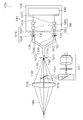
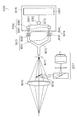
- FIG. 1 shows the luminance meter of the first embodiment.
- the luminance meter 1000 includes an objective lens 1010, a field stop 1011, a bundle fiber 1012, a color filter group 1013, a light receiving sensor group 1014, a derivation mechanism 1015, a mirror 1016, and a viewfinder system 1017.
- the color filter group 1013 includes a first color filter 1030 and a second color filter 1031.
- the light receiving sensor group 1014 includes a first light receiving sensor 1040 and a second light receiving sensor 1041.
- the derivation mechanism 1015 includes an amplification mechanism 1050, a conversion mechanism 1051, and an arithmetic mechanism 1052.
- the amplification mechanism 1050 includes a first amplification circuit 1060 and a second amplification circuit 1061.
- the conversion mechanism 1051 includes a first conversion circuit 1070 and a second conversion circuit 1071.
- the beam bundle 1080 to be measured is converged by the objective lens 1010.
- the objective optical system including the objective lens 1010 may be replaced with another type of objective optical system.
- the peripheral light bundle 1100 of the converged light bundle 1080 is limited by the field stop 1011.
- the restricted light bundle 1100 is incident on the incident end 1110 of the bundle fiber 1012.
- the incident light bundle 1100 is branched by the bundle fiber 1012.
- the first light bundle 1120 and the second light bundle 1121 obtained by the branching are emitted from the first emission end 1130 and the second emission end 1131 of the bundle fiber 1012 respectively.
- the branch mechanism composed of the bundle fiber 1012 may be replaced with another type of branch mechanism.
- the emitted first light bundle 1120 and second light bundle 1121 are transmitted through the first color filter 1030 and the second color filter 1031, respectively.
- the transmitted first beam bundle 1120 and second beam bundle 1121 are received by the first light receiving sensor 1040 and the second light receiving sensor 1041, respectively.
- the first light receiving sensor 1040 and the second light receiving sensor 1041 output a first electric signal and a second electric signal corresponding to the received first light bundle 1120 and second light bundle 1121, respectively.
- the deriving mechanism 1015 derives the luminance value LV corresponding to the spectral distribution of the light beam 1080 to be measured from the first electric signal and the second electric signal.
- the first electric signal and the second electric signal are amplified by the first amplifier circuit 1060 and the second amplifier circuit 1061, respectively.
- the amplification factors when the first amplification circuit 1060 and the second amplification circuit 1061 amplify the first electric signal and the second electric signal are respectively referred to as the first amplification factor G1 and the second amplification factor.
- the rate is G2.
- the first amplifier circuit 1060 and the second amplifier circuit 1061 may be omitted.
- the amplified first electric signal and second electric signal are converted from analog to digital into a first signal value S1 and a second signal value S2 by a first conversion circuit 1070 and a second conversion circuit 1071, respectively. Is done.
- the calculation mechanism 1052 is a microcomputer or the like, and calculates a luminance value LV from the first signal value S1 and the second signal value S2.
- Each of the relative spectral response S1 ( ⁇ ) realized by the first color filter 1030 and the relative spectral response S2 ( ⁇ ) realized by the second color filter 1031 has a standard relative luminous sensitivity V ( ⁇ ). Can be approximated.
- the relative spectral response S1 ( ⁇ ) indicates the relationship between the measured spectral distribution of the light beam 1080 and the first signal value S1.
- the relative spectral response S2 ( ⁇ ) indicates the relationship between the measured spectral distribution of the light beam 1080 and the second signal value S2. Therefore, the relative spectral response S1 ( ⁇ ) and the relative spectral response S2 ( ⁇ ) are mainly affected by the spectral transmittances of the first color filter 1030 and the second color filter 1031 respectively. It is also affected by the spectral transmittance of 1010 and the spectral transmittance of the bundle fiber 1012, and is also affected by the spectral sensitivity of the light receiving sensor 1040 and the light receiving sensor 1041, respectively.
- the number of branches of the bundle fiber 1012 may be increased.
- the number of branches of the bundle fiber 1012 is increased, according to the number of branches of the bundle fiber 1012, the number of beam bundles, the number of emission ends, the number of color filters, the number of light receiving sensors, the number of amplifier circuits, the number of conversion circuits The number, the number of electrical signals, the number of signal values, etc. are increased.
- the central light bundle 1101 of the converged light bundle 1080 is reflected by the mirror 1016.
- the reflected light bundle 1101 is guided to the finder system 1017.
- the viewfinder system 1017 generates a viewfinder image from the guided light beam 1101.
- the mirror 1016 and the viewfinder system 1017 may be omitted.
- the wavelength error ⁇ of the color filter is an index expressing the wavelength shift from the relative spectral response realized by the best color filter of the relative spectral response realized by the color filter.
- An index other than the wavelength error ⁇ of the color filter may be used.
- the centroid wavelength may be changed to another type of characteristic wavelength.
- the center-of-gravity wavelength may be changed to a peak wavelength, a half-value wavelength, or the like.
- a relative spectral response other than the relative spectral response of the best color filter may be used as a reference.
- the relative spectral response that matches the standard relative luminous sensitivity may be used as a reference.
- Each of the first color filter 1030 and the second color filter 1031 is an interference type. For this reason, the deviation from the relative spectral response realized by the best color filter of the relative spectral response realized by each of the first color filter 1030 and the second color filter 1031 is expressed by a wavelength error. . Even when each of the first color filter 1030 and the second color filter 1031 is not an interference type, the color filter having the best relative spectral response realized by each of the first color filter 1030 and the second color filter 1031. In some cases, the deviation from the relative spectral responsivity realized by is represented by a wavelength error.
- each of the first color filter 1030 and the second color filter 1031 is not an interference type, from the standard relative luminous sensitivity V ( ⁇ ) of the relative spectral response S0 ( ⁇ ) employed in the luminance meter 1000.
- a technique for suppressing the deviation f 1 ′ is employed.
- the wavelength error ⁇ 1 of the first color filter 1030 is negative, and the wavelength error ⁇ 2 of the second color filter 1031 is positive.
- the influence ⁇ S2 ( ⁇ ) on the spectral response S0 ( ⁇ ) can be canceled out.
- the signal value is such that the influence ⁇ S1 ( ⁇ ) and the influence ⁇ S2 ( ⁇ ), which are a set of the two color filters 1030 and 1031 of the influence ⁇ Si ( ⁇ ) of the wavelength error ⁇ i of the i-th color filter cancel each other.
- the coefficient Ci multiplied by Si is made different between the two signal values S1 and S2.
- the calculation mechanism 1052 performs weighting that makes the contribution of the i-th electrical signal to the luminance value LV different between the two electrical signals. .
- each of the first coefficient C1 and the second coefficient C2 is a weighting coefficient
- the sum S0 is a weighting of the first signal value S1 and the second signal value S2.
- the first amplification factor G1 and the second amplification factor G2 are the same.
- the wavelength error ⁇ i of the i-th color filter is multiplied by the weighting coefficient Ci multiplied by the signal value Si obtained by converting the electric signal output from the light receiving sensor that receives the light bundle transmitted through the i-th color filter.
- the product C1 ⁇ ⁇ 1 and the product C2 ⁇ ⁇ 2 desirably cancel out completely.
- the sum C1 ⁇ ⁇ 1 + C2 ⁇ ⁇ 2 of the product C1 ⁇ ⁇ 1 and the product C2 ⁇ ⁇ 2 becomes zero.
- the effect of reducing the deviation f 1 ′ can be obtained.
- the influence ⁇ S1 ( ⁇ ) and the influence ⁇ S2 ( ⁇ ) cancel each other, and the relative spectral response S0 ( ⁇ ) approaches the relative spectral response realized by the best color filter.
- the first color filter 1030 and the second color filter 1031 that can realize only the relative spectral responsivities S1 ( ⁇ ) and S2 ( ⁇ ) in which the deviation f 1 ′ does not satisfy the standard, respectively, and the deviation f 1 ′.
- the luminance meter 1000 having a relative spectral response S0 ( ⁇ ) satisfying the standard can be realized. Therefore, the deviation f 1 ′ can be reduced without increasing the production cost of the luminance meter 1000.
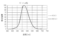
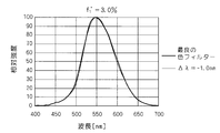
- the graph of FIG. 2 shows the relative spectral response and wavelength realized by a color filter having a wavelength error ⁇ of ⁇ 2.1 nm.
- the relative spectral responsivity realized by the color filter having an error ⁇ of +1.7 nm is shown.
- the graph of FIG. 3 shows the standard relative luminous sensitivity and the relative spectral response of the luminance meter.
- the wavelength error ⁇ 1 of the first color filter 1030 is ⁇ 2.1 nm, and the relative spectral response S1 ( ⁇ ) realized by the first color filter 1030 is the relative spectral response S1 ( ⁇ ) shown in FIG.
- the wavelength error ⁇ 2 of the second color filter 1031 is +1.7 nm, and the relative spectral response S2 ( ⁇ ) realized by the second color filter 1031 is the relative spectral response S2 ( ⁇ ) shown in FIG.
- the first coefficient C1 is set to 0.8
- the second coefficient C2 is set to 1.0.
- the product C1 ⁇ ⁇ 1 becomes ⁇ 1.7
- the product C2 ⁇ ⁇ 2 becomes 1.7
- the product C1 ⁇ ⁇ 1 and the product C2 ⁇ ⁇ 2 cancel each other.
- the relative spectral response S0 ( ⁇ ) of the luminance meter 1000 becomes the relative spectral response S0 ( ⁇ ) shown in FIG. 3, and the standard relative luminous sensitivity of the relative spectral response S0 ( ⁇ ) of the luminance meter 1000 is obtained.
- the deviation f 1 ′ from V ( ⁇ ) becomes 1.4%
- the luminance meter 1000 becomes L level. That is, the luminance meter 1000 that can achieve the L class can be produced using the first color filter 1030 and the second color filter 1031 that should not achieve the L class.
- FIG. 4 shows a method for producing a luminance meter.
- color filters that are candidates for the first color filter 1030 and the second color filter 1031 are prepared in step 1140.
- step 1141 the wavelength error of each of the prepared color filters is measured.
- the wavelength error of each of the prepared color filters is measured through a step of measuring the spectral transmittance of each of the prepared color filters with a spectrophotometer.
- the centroid wavelength is in the wavelength range of 380-780 nm.
- Spectral reflectance may be measured instead of spectral transmittance.
- the wavelength range of 380-780 nm may be replaced with another wavelength range.
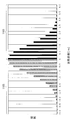
- the histogram of FIG. 5 shows the distribution of wavelength errors.
- a color filter having a wavelength error suitable for the first color filter 1030 and a color filter having a wavelength error suitable for the second color filter 1031 are selected from the prepared color filters.
- the prepared color filters are classified into groups A1 and A2.
- a wavelength error range that is negative and a wavelength error range that is positive are respectively defined.
- Class ranges 1165 and 1166 in the histogram of FIG. 5 belong to the ranges of wavelength errors defined in groups A1 and A2, respectively.
- each of the prepared color filters belongs to a group in which a range of wavelength errors including the wavelength errors of each of the prepared color filters is defined.
- the color filters used as the first color filter 1030 and the second color filter 1031 are selected from the color filters belonging to the groups A1 and A2, respectively.
- step 1143 the luminance meter 1000 is assembled using the two selected color filters as the first color filter 1030 and the second color filter 1031.
- the objective lens 1010 forms an image of the beam bundle 1080 to be measured at the imaging position 1150.
- An opening 1160 formed in the field stop 1011 is disposed at the imaging position 1150.
- the incident end 1110 is arranged away from the opening 1160.
- the incident end 1110 is arranged away from the imaging position 1150, and the light beam 1100 enters the incident end 1110 in a state where it is not focused.
- the diameter of the incident end 1110 is larger than that when the light beam 1100 is incident on the incident end 1110 with the light beam 1100 being in focus. Must.
- the bundle fiber 1012 has a branch and has a first emission end 1130 and a second emission end 1131.
- the diameters of the first exit end 1130 and the second exit end 1131 are smaller than the diameter of the entrance end 1110. Thereby, even when the diameter of the incident end 1110 is increased, the entire first light beam 1120 and second light beam 1121 emitted from the first emission end 1130 and the second emission end 1131 are
- the first color filter 1030 and the second color filter 1031 can be transmitted through the first color filter 1030 and the second color filter 1031, respectively.
- the sensor 1040 and the second light receiving sensor 1041 can receive light.
- the influence ⁇ S1 of the wavelength error ⁇ 1 of the first color filter 1030 on the relative spectral response S0 ( ⁇ ) of the luminance meter 1000 ⁇ ) and the wavelength error ⁇ 2 of the second color filter 1031 affect the relative spectral responsivity S0 ( ⁇ ) of the luminance meter 1000, and the first amplification factor G1 and the second amplification so that the influence ⁇ S2 ( ⁇ ) cancels each other.
- the rates G2 can be made different from each other.
- the influence ⁇ S1 ( ⁇ ) which is a set of the two color filters 1030 and 1031 of the influence ⁇ Si ( ⁇ ) of the wavelength error ⁇ i of the i-th color filter on the relative spectral response S0 ( ⁇ ) of the luminance meter 1000.
- the amplification factor Gi is made different between the two electric signals (the first electric signal and the second electric signal) so that the influence ⁇ S2 ( ⁇ ) cancels out.
- the first amplification factor G1 and the second amplification factor G2 indicate the magnitudes of the contribution of the first electrical signal and the second electrical signal to the luminance value LV, respectively.
- the first modification of the first embodiment In the example, by making the first amplification factor G1 and the second amplification factor G2 different from each other, the magnitude of the contribution of one electrical signal to the luminance value LV is changed to two electrical signals (first electrical signal). And the second electrical signal) are weighted by the amplification mechanism 1050.
- the first amplification factor G1 is set to the wavelength error ⁇ 1 of the first color filter 1030 so that the influence ⁇ S1 ( ⁇ ) and the influence ⁇ S2 ( ⁇ ) cancel each other.
- the first amplification factor G1 and the second amplification factor G2 are set by circuit constants of elements constituting the amplifier 1 and the amplifier 2, respectively.
- the element used for setting the circuit constant is typically a resistor.
- the deviation f 1 ′ can be reduced without increasing the production cost of the luminance meter 1000.
- Second Modification of First Embodiment 4.1 Suppression of Relative Spectral Response of Luminometer from Standard Specific Visibility
- the wavelength of the first color filter 1030 The error ⁇ 1 and the wavelength error ⁇ 2 of the second color filter 1031 cancel each other. That is, the wavelength error ⁇ 1 and the wavelength error ⁇ 2 that are a set of the two color filters 1030 and 1031 having the wavelength error ⁇ i of the i-th color filter cancel each other.
- the first coefficient C1 and the second coefficient C2 are set to be the same, and the first amplification is performed.
- the rate G1 and the second gain G2 are the same.
- the histogram in Fig. 6 shows the distribution of wavelength errors.
- a color filter having a wavelength error suitable for the first color filter 1030 and a color filter having a wavelength filter suitable for the second color filter 1031 are prepared. Selected. Accordingly, a color filter having a wavelength error suitable for each of the two color filters 1030 and 1031 included in the luminance meter 1000 is selected from the prepared color filters.
- the prepared color filters are classified into groups A1, A2, B1, B2, C1, and C2 shown in Table 1 when selecting two color filters.
- Class ranges 1170, 1171, 1172, 1173, 1174 and 1175 in the histogram of FIG. 6 belong to the ranges of wavelength errors defined in the groups A1, A2, B1, B2, C1 and C2, respectively.
- the typical wavelength errors defined for groups A1, A2, B1, B2, C1 and C2 are preferably within the range of wavelength errors defined for groups A1, A2, B1, B2, C1 and C2, respectively. Is in the middle of the range of wavelength errors defined in groups A1, A2, B1, B2, C1 and C2.
- the wavelength error ranges defined in the groups A2, B2, and C2 are obtained by inverting the signs of the wavelength error ranges defined in the groups A1, B1, and C1, respectively.
- the representative wavelength errors defined in the groups A2, B2, and C2 are obtained by inverting the signs of the representative wavelength errors defined in the groups A1, B1, and C1, respectively.
- the number of groups may be increased or decreased.
- the range of wavelength error and the representative wavelength error defined in each of the groups A1, A2, B1, B2, C1, and C2 may be changed.
- each of the prepared color filters belongs to a group in which a range of wavelength errors including the wavelength errors of each of the prepared color filters is defined.
- the color filters used as the first color filter 1030 and the second color filter 1031 are selected from the color filters belonging to the first group and the color filters belonging to the second group, respectively.
- the first group and the second group are selected such that the representative wavelength error defined in the first group and the representative wavelength error defined in the second group cancel each other.
- the color filters used as the first color filter 1030 and the second color filter 1031 may be selected from the color filters belonging to the groups A1 and A2 as shown in the combination a in Table 1.
- the color filters belonging to the groups B1 and B2 may be selected as shown in the combination b in Table 1, or the color filters belonging to the groups C1 and C2 as shown in the combination c in Table 1 may be selected. Good.
- the representative wavelength error defined in the first group and the representative wavelength error defined in the second group completely cancel each other, the representative wavelength error defined in the first group and the second group
- the simple sum of the representative wavelength errors defined in (1) is zero.
- the wavelength error ⁇ 1 of the first color filter 1030 and the wavelength error ⁇ 2 of the second color filter 1031 cancel each other. That is, the wavelength error ⁇ 1 and the wavelength error ⁇ 2 that are a set of the two color filters 1030 and 1031 having the wavelength error ⁇ i of the i-th color filter cancel each other.
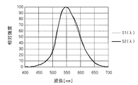
- the graph of FIG. 7 shows relative spectral responsivity and wavelength realized by a color filter having a wavelength error ⁇ of ⁇ 1.2 nm.
- the relative spectral responsivity realized by a color filter with an error ⁇ of +0.5 nm is shown.
- the graph of FIG. 8 shows the standard relative luminous sensitivity and the relative spectral response of the luminance meter.
- the wavelength error ⁇ 1 of the first color filter 1030 is ⁇ 1.2 nm, and the relative spectral response S1 ( ⁇ ) realized by the first color filter 1030 is the relative spectral response S1 ( ⁇ ) shown in FIG.
- the wavelength error ⁇ 2 of the second color filter 1031 is +0.5 nm, and the relative spectral response S2 ( ⁇ ) realized by the second color filter 1031 is the relative spectral response S2 ( ⁇ ) shown in FIG.
- the color filters used as the first color filter 1030 and the second color filter 1031 are respectively selected from the color filters belonging to the groups B1 and B2, and the representative filters defined in the group B1 are selected.
- the wavelength error and the representative wavelength error defined in group B2 cancel each other.
- the relative spectral response S0 ( ⁇ ) of the luminance meter 1000 becomes the relative spectral response S0 ( ⁇ ) shown in FIG. 8, and the standard relative luminous sensitivity V of the relative spectral response S0 ( ⁇ ) of the luminance meter 1000 is obtained.
- the deviation f 1 ′ from ( ⁇ ) becomes 2.0%, and the luminance meter 1000 becomes the L level. That is, the luminance meter 1000 that can achieve the L class can be realized by using the first color filter 1030 and the second color filter 1031 that should not achieve the L class.
- the deviation of the relative spectral response of the luminance meter 1000 from the spectral ratio visibility is reduced without increasing the production cost of the luminance meter 1000. it can.
- the second embodiment relates to a luminance meter.
- FIG. 9 shows the luminance meter of the second embodiment.
- the luminance meter 2000 includes an objective lens 2010, a field stop 2011, a bundle fiber 2012, a color filter group 2013, a light receiving sensor group 2014, a derivation mechanism 2015, a mirror 2016, and a finder system 2017.
- the color filter group 2013 includes a first color filter 2030 and a second color filter 2031.
- the light receiving sensor group 2014 includes a first light receiving sensor 2040 and a second light receiving sensor 2041.
- the derivation mechanism 2015 includes a merging circuit 2050, an amplification mechanism 2051, a conversion mechanism 2052, and an arithmetic mechanism 2053.
- the amplification mechanism 2051 includes an amplification circuit 2060.
- the conversion mechanism 2052 includes a conversion circuit 2070.
- the objective lens 2010, the field stop 2011, the bundle fiber 2012, the light receiving sensor group 2014, the mirror 2016, and the viewfinder system 2017 according to the second embodiment are respectively the objective lens 1010, the field stop 1011, the bundle fiber 1012, and the light receiving system according to the first embodiment.
- the sensor group 1014, the mirror 1016, and the finder system 1017 are the same.
- the first electric signal and the second electric signal output from the light receiving sensor group 2014 are merged by the merge circuit 2050.
- the combined electrical signal is amplified by the amplifier circuit 2060.
- the amplified electrical signal is analog / digital converted into a signal value S by the conversion circuit 2070.
- the calculation mechanism 2053 is a microcomputer or the like, and calculates the luminance value LV from the signal value S.
- the junction circuit 2050 is a circuit that connects the first light receiving sensor 2040 and the second light receiving sensor 2041 in parallel.
- the energy of the combined electric signal is the sum of the energy of the first electric signal and the energy of the second electric signal.
- the merging circuit 2050 may be a circuit that connects the first light receiving sensor 2040 and the second light receiving sensor 2041 in series.
- the wavelength error ⁇ 1 of the first color filter 2030 is the same as the second modification of the first embodiment.
- the wavelength error ⁇ 2 of the second color filter 2031 cancels out. Therefore, at the stage of the first electric signal and the second electric signal, the influence ⁇ S1 ( ⁇ ) of the wavelength error ⁇ 1 of the first color filter 2030 on the relative spectral response S0 ( ⁇ ) of the luminance meter 2000 and the first electric signal.
- the influence ⁇ S2 ( ⁇ ) of the wavelength error ⁇ 2 of the second color filter 2031 on the relative spectral response S0 ( ⁇ ) of the luminance meter 2000 can already be canceled.
- the influence ⁇ S1 ( ⁇ ) and the influence ⁇ S2 ( ⁇ ) cancel out at the stage of the luminance value LV.
- the deviation of the relative spectral response of the luminance meter 2000 from the spectral ratio visibility can be reduced without increasing the production cost of the luminance meter 2000.
- the number of amplifier circuits and conversion circuits is reduced, and the production cost of the luminance meter 2000 is further reduced.
- the third embodiment relates to a luminance meter.
- FIG. 10 shows the luminance meter of the third embodiment.
- the luminance meter 3000 includes an objective lens 3010, a field stop 3011, a bundle fiber 3012, a color filter group 3013, a light receiving sensor group 3014, a derivation mechanism 3015, a mirror 3016, and a viewfinder system 3017.
- the color filter group 3013 includes a first color filter 3030 and a second color filter 3031.
- the light receiving sensor group 3014 includes a first light receiving sensor 3040 and a second light receiving sensor 3041.
- the derivation mechanism 3015 includes an amplification mechanism 3050, a junction circuit 3051, a conversion mechanism 3052, and an arithmetic mechanism 3053.
- the amplification mechanism 3050 includes a first amplification circuit 3060 and a second amplification circuit 3061.
- the conversion mechanism 3052 includes a conversion circuit 3070.
- the objective lens 3010, the field stop 3011, the bundle fiber 3012, the color filter group 3013, and the light receiving sensor group 3014 of the third embodiment are respectively the objective lens 1010, the field stop 1011, the bundle fiber 1012, and the color filter group of the first embodiment. 1013 and the light receiving sensor group 1014 are the same.
- the first electric signal and the second electric signal output from the light receiving sensor group 3014 are amplified by the first amplifier circuit 3060 and the second amplifier circuit 3061, respectively.
- the amplified first electric signal and second electric signal are merged by the merge circuit 3051.
- the combined electrical signal is analog / digital converted to a signal value S by the conversion circuit 3070.
- the calculation mechanism 3053 is a microcomputer or the like, and calculates the luminance value LV from the signal value S.
- the wavelength error ⁇ 1 of the first color filter 3030 is the same as in the first modification of the first embodiment.
- the luminance meter 3000 on the relative spectral response S0 ( ⁇ ) ⁇ S1 ( ⁇ ) and the wavelength error ⁇ 2 of the second color filter 3031 on the luminance meter 3000 relative spectral response S0 ( ⁇ ) ⁇ S2 ( ⁇ ) are weighted by the amplification mechanism 3050 so as to cancel each other.
- the influence ⁇ S1 ( ⁇ ) and the influence ⁇ S2 ( ⁇ ) can already be canceled at the stage of the amplified first electric signal and second electric signal.
- the influence ⁇ S1 ( ⁇ ) and the influence ⁇ S2 ( ⁇ ) cancel out at the stage of the luminance value LV.
- the deviation of the relative spectral response of the luminance meter 3000 from the spectral relative luminous sensitivity can be reduced without increasing the production cost of the luminance meter 3000.
- the number of conversion circuits is reduced, and the production cost of the luminance meter 3000 is further reduced.
- the fourth embodiment relates to a luminance meter.
- FIG. 11 shows the luminance meter of the fourth embodiment.
- the luminance meter 4000 includes an objective lens 4010, a field stop 4011, a bundle fiber 4012, a color filter group 4013, a light receiving sensor group 4014, a lead-out mechanism 4015, a mirror 4016, and a finder system 4017.
- the color filter group 4013 includes a first color filter 4030, a second color filter 4031, and a third color filter 4032.
- the light receiving sensor group 4014 includes a first light receiving sensor 4040, a second light receiving sensor 4041, and a third light receiving sensor 4042.
- the derivation mechanism 4015 includes an amplification mechanism 4050, a conversion mechanism 4051, and an arithmetic mechanism 4052.
- the amplification mechanism 4050 includes a first amplification circuit 4060, a second amplification circuit 4061, and a third amplification circuit 4062.
- the conversion mechanism 4051 includes a first conversion circuit 4070, a second conversion circuit 4071, and a third conversion circuit 4072.
- the objective lens 4010, the field stop 4011, the mirror 4016, and the finder system 4017 of the fourth embodiment are the same as the objective lens 1010, the field stop 1011, the mirror 1016, and the finder system 1017 of the first embodiment, respectively.
- the light beam 4100 limited by the field stop 4011 is incident on the incident end 4110 of the bundle fiber 4012.
- the incident light bundle 4100 is branched by the bundle fiber 4012.
- the first beam bundle 4120, the second beam bundle 4121, and the third beam bundle 4122 obtained by the branching are respectively the first emission end 4130, the second emission end 4131, and the third emission ray of the bundle fiber 4012.
- the light is emitted from the end 4132.
- the emitted first light bundle 4120, second light bundle 4121, and third light bundle 4122 are transmitted through the first color filter 4030, the second color filter 4031, and the third color filter 4032, respectively.
- the transmitted first light bundle 4120, second light bundle 4121, and third light bundle 4122 are received by the first light receiving sensor 4040, the second light receiving sensor 4041, and the third light receiving sensor 4042, respectively.
- the first light receiving sensor 4040, the second light receiving sensor 4041, and the third light receiving sensor 4042 respectively correspond to the first light bundle 4120, the second light bundle 4121, and the third light bundle 4122 that are received.
- 1 electrical signal, 2nd electrical signal, and 3rd electrical signal are output.
- the deriving mechanism 4015 derives the luminance value LV corresponding to the spectral distribution of the light beam 4080 to be measured from the first electric signal, the second electric signal, and the third electric signal.
- the first electric signal, the second electric signal, and the third electric signal are amplified by the first amplifier circuit 4060, the second amplifier circuit 4061, and the third amplifier circuit 4062, respectively.
- the amplification factor when the first amplifier circuit 4060, the second amplifier circuit 4061, and the third amplifier circuit 4062 amplify the first electric signal, the second electric signal, and the third electric signal is expressed as The first amplification factor G1, the second amplification factor G2, and the third amplification factor G3, respectively.
- the amplified first electric signal, second electric signal, and third electric signal are converted into a first signal value by the first conversion circuit 4070, the second conversion circuit 4071, and the third conversion circuit 4072, respectively.
- Analog / digital conversion is performed into S1, the second signal value S2, and the third signal value S3.
- the calculation mechanism 4052 is a microcomputer or the like, and calculates the luminance value LV from the first signal value S1, the second signal value S2, and the third signal value S3.
- Each of the responsiveness S3 ( ⁇ ) is approximated to the standard relative luminous sensitivity V ( ⁇ ).
- the relative spectral response S1 ( ⁇ ) indicates the relationship between the spectral distribution of the light bundle 4080 to be measured and the first signal value S1.
- the relative spectral response S2 ( ⁇ ) indicates the relationship between the spectral distribution of the light bundle 4080 to be measured and the second signal value S2.
- the relative spectral response S3 ( ⁇ ) indicates the relationship between the measured spectral distribution of the light beam 4080 and the third signal value S3.
- the wavelength error ⁇ 1 of the first color filter 4030, the second color filter 4031, and so on cancel each other. That is, the wavelength error ⁇ 1, the wavelength error ⁇ 2, and the wavelength error ⁇ 3, which are a set of the three color filters 4030, 4031, and 4032 with the wavelength error ⁇ i of the i-th color filter cancel each other.
- the first coefficient C1, the second coefficient C2, and the third coefficient C3 are set to be the same as each other.
- the amplification factor G1, the second amplification factor G2, and the third amplification factor G3 are the same.
- a color filter having a wavelength error suitable for the first color filter 4030, a color filter having a wavelength error suitable for the second color filter 4031, and a wavelength error suitable for the third color filter 4032 Is selected from the prepared color filters. Accordingly, a color filter having a wavelength error suitable for each of the three color filters included in the luminance meter 4000 is selected from the prepared color filters.
- the prepared color filters are classified into groups X, A1, A2, B1, B2, C1, C2, D1 and D2 shown in Table 2.
- the typical wavelength errors defined in groups X, A1, A2, B1, B2, C1, C2, D1, and D2 are defined in groups X, A1, A2, B1, B2, C1, C2, D1, and D2, respectively.
- the wavelength error ranges defined in the groups A2, B2, C2, and D2 are obtained by inverting the signs of the wavelength error ranges defined in the groups A1, B1, C1, and D1, respectively.
- the representative wavelength errors defined in the groups A2, B2, C2, and D2 are obtained by inverting the signs of the representative wavelength errors defined in the groups A1, B1, C1, and D1, respectively.
- the number of groups may be increased or decreased.
- the wavelength error range and the representative wavelength error defined in each of the groups X, A1, A2, B1, B2, C1, C2, D1, and D2 may be changed.
- each of the prepared color filters belongs to a group in which a range of wavelength errors including the wavelength errors of each of the prepared color filters is defined.
- Color filters used as the first color filter 4030, the second color filter 4031, and the third color filter 4032 are selected from the color filters belonging to the first group, the second group, and the third group, respectively. Is done.
- the first group, the second group, and the third group are defined in the representative wavelength error defined in the first group, the representative wavelength error defined in the second group, and the third group.
- the representative wavelength error is selected to cancel.
- the color filters used as the first color filter 4030, the second color filter 4031, and the third color filter 4032 belong to the groups X, A1, and A2, respectively, as shown in the combination a in Table 1.
- color filters may be selected from color filters belonging to groups X, B1, and B2 as shown in combination b of Table 1, or group X as shown in combination c of Table 1.
- C1 and C2 may be selected from the color filters belonging to groups X, D1 and D2, as shown in the combination d of Table 1. It is also permissible that no selection is made from color filters belonging to group X in which a representative wavelength error of zero is defined. Groups A2, B2, and C2 in which the number of color filters selected from the color filters belonging to the groups A1, B1, C1, or D1 in which the representative wavelength errors that are negative are defined are positive are defined. Alternatively, it may be different from the number of color filters selected from the color filters belonging to D2.
- Two or more color filters may be selected from the color filters belonging to one group.
- the color filters used as the first color filter 4030, the second color filter 4031, and the third color filter 4032 are grouped into groups D1, A2, and C2, respectively, as shown in the combination e of Table 2.
- the representative wavelength error defined in the first group, the representative wavelength error defined in the second group, and the representative wavelength error defined in the third group completely cancel each other, the first group The sum of the representative wavelength error defined in 1), the representative wavelength error defined in the second group, and the representative wavelength error defined in the third group becomes zero.
- the wavelength error ⁇ 1 of the first color filter 4030, the wavelength error ⁇ 2 of the second color filter 4031, and the wavelength error ⁇ 3 of the third color filter 4032 cancel each other. That is, the wavelength error ⁇ 1, the wavelength error ⁇ 2, and the wavelength error ⁇ 3, which are a set of the three color filters 4030, 4031, and 4032 of the wavelength error of the i-th color filter cancel each other.
- the first electric signal, the second electric signal, and the third electric signal output from the light receiving sensor group 4014 are merged by the merge circuit, and the merged electric signal is amplified by the amplifier circuit. Then, the amplified electric signal may be converted into a signal value by the conversion circuit, and the calculation mechanism may calculate the luminance value LV from the signal value. Further, as in the fourth embodiment, the amplified first electric signal, second electric signal, and third electric signal output from the amplification mechanism 4050 are merged by the merge circuit, and the merged electric signal is converted. It may be converted into a signal value by a circuit, and the calculation mechanism may calculate the luminance value LV from the signal value.
- Weighting may be performed by the calculation mechanism 4052 so as to cancel each other.
- weighting may be performed by the amplification mechanism 4050 so that the influence ⁇ S1 ( ⁇ ), the influence ⁇ S2 ( ⁇ ), and the influence ⁇ S3 ( ⁇ ) cancel each other.
- the deviation of the relative spectral response of the luminance meter 4000 from the spectral ratio visibility can be reduced without increasing the production cost of the luminance meter 4000.
- the fifth embodiment relates to a color luminance meter.
- a color luminance meter is a measuring instrument that measures the color and luminance of a light source.
- FIG. 12 shows a color luminance meter of the fifth embodiment.
- the color luminance meter 5000 includes an objective lens 5010, a field stop 5011, a bundle fiber 5012, a color filter group 5013X, a light receiving sensor group 5014X, a derivation mechanism 5015X, a color filter group 5013Y, a light receiving sensor group 5014Y, A derivation mechanism 5015Y, a color filter group 5013Z, a light receiving sensor group 5014Z, a derivation mechanism 5015Z, a mirror 5016, and a finder system 5017 are provided.
- Each of the color filter group 5013X, the color filter group 5013Y, and the color filter group 5013Z includes a first color filter 5030 and a second color filter 5031.
- Each of the light receiving sensor group 5014X, the light receiving sensor group 5014Y, and the light receiving sensor group 5014Z includes a first light receiving sensor 5040 and a second light receiving sensor 5041.
- Each of the derivation mechanism 5015X, the derivation mechanism 5015Y, and the derivation mechanism 5015Z includes an amplification mechanism 5050, a conversion mechanism 5051, and an arithmetic mechanism 5052.
- the amplification mechanism 5050 includes a first amplification circuit 5060 and a second amplification circuit 5061.
- the conversion mechanism 5051 includes a first conversion circuit 5070 and a second conversion circuit 5071.
- the objective lens 5010, the field stop 5011, the mirror 5016, and the finder system 5017 of the fifth embodiment are the same as the objective lens 1010, the field stop 1011, the mirror 1016, and the finder system 1017 of the first embodiment, respectively.
- the light beam 5100 limited by the field stop 5011 is incident on the incident end 5110 of the bundle fiber 5012.
- the incident light bundle 5100 is branched by the bundle fiber 5012.
- the bundle of rays 5120X, the bundle of rays 5121X, the bundle of rays 5120Y, the bundle of rays 5121Y, the bundle of rays 5120Z, and the bundle of rays 5121Z obtained by the branching are respectively the exit end 5130X, exit end 5131X, exit end 5130Y, exit end 5131Y of the bundle fiber 5012.
- the light is emitted from the emission end 5130Z and the emission end 5131Z.
- the description of the configuration for obtaining the stimulus value X is the description of the configuration for obtaining the stimulus value Y by replacing “X” and “x” in the description with “Y” and “y”, respectively.
- “X” and “x” in the description are read as “Z” and “z”, respectively, to explain the configuration for obtaining the stimulus value Z.
- the emitted first beam bundle 5120X and second beam bundle 5121X are transmitted through the first color filter 5030 and the second color filter 5031 belonging to the color filter group 5013X, respectively.
- the transmitted first light bundle 5120X and second light bundle 5121X are received by the first light receiving sensor 5040 and the second light receiving sensor 5041 belonging to the light receiving sensor group 5014X, respectively.
- the first light receiving sensor 5040 and the second light receiving sensor 5041 belonging to the light receiving sensor group 5014X respectively include a first electric signal and a second light signal corresponding to the received first light bundle 5120X and second light bundle 5121X. Outputs electrical signals.
- the deriving mechanism 5015X derives the stimulus value X corresponding to the spectral distribution of the light beam 5080 to be measured from the first electric signal and the second electric signal.
- the first electric signal and the second electric signal are amplified by the first amplifier circuit 5060 and the second amplifier circuit 5061 belonging to the derivation mechanism 5015X, respectively.
- the amplified first electric signal and second electric signal are respectively converted into the first signal value SX1 and the second signal value SX2 by the first conversion circuit 5070 and the second conversion circuit 5071 belonging to the derivation mechanism 5015X.
- An arithmetic mechanism 5052 belonging to the derivation mechanism 5015X is a microcomputer or the like, and calculates a luminance value LV from the first signal value SX1 and the second signal value SX2.
- the color luminance meter 5000 having the wavelength error ⁇ 1X of the first color filter 5030 belonging to the color filter group 5013X Influence on relative spectral response S0X ( ⁇ ) ⁇ S1X ( ⁇ ) and influence of wavelength error ⁇ 2X of second color filter 5031 belonging to color filter group 5013X on relative spectral response S0X ( ⁇ ) of color luminance meter 5000 Weighting is performed by the calculation mechanism 5052 or the amplification mechanism 5050 so that ( ⁇ ) cancels each other. In the color filter group 5013X, the wavelength error ⁇ 1X and the wavelength error ⁇ 2X may be canceled out.
- the deviation of the relative spectral response of the color luminance meter 5000 from the color matching function can be reduced without increasing the production cost of the color luminance meter 5000.
- the sixth embodiment relates to an illuminometer.
- An illuminometer is a measuring instrument that measures the illuminance of a light source.
- FIG. 13 shows an illuminometer of the sixth embodiment.
- the illuminometer 6000 includes a diffusing sphere 6010, a diffusing plate group 6011, a color filter group 6012, a light receiving sensor group 6013, and a derivation mechanism 6014.
- the diffusion plate group 6011 includes a first diffusion plate 6020, a second diffusion plate 6021, and a third diffusion plate 6022.
- the color filter group 6012 includes a first color filter 6030, a second color filter 6031, and a third color filter 6032.
- the light receiving sensor group 6013 includes a first light receiving sensor 6040, a second light receiving sensor 6041, and a third light receiving sensor 6042.
- the derivation mechanism 6014 includes an amplification mechanism 6050, a conversion mechanism 6051, and an arithmetic mechanism 6052.
- the amplification mechanism 6050 includes a first amplification circuit 6060, a second amplification circuit 6061, and a third amplification circuit 6062.
- the conversion mechanism 6051 includes a first conversion circuit 6070, a second conversion circuit 6071, and a third conversion circuit 6072.
- the diffusion sphere 6010 functions as a transmission type diffusion member, the light beam 6080 to be measured is diffused by the diffusion sphere 6010 when passing through the diffusion sphere 6010. As a result, the light beam 6080 to be measured is branched by the diffusing sphere 6010.
- the first beam bundle 6090, the second beam bundle 6091, and the third beam bundle 6092 obtained by the branching are directed to the first diffusion plate 6020, the second diffusion plate 6021, and the third diffusion plate 6022, respectively.
- the diffusing sphere 6010 that is a hemispherical diffusing member may be replaced with a non-hemispheric diffusing member.
- the diffusion sphere 6010 may be replaced with a flat diffusion plate.
- the first light beam 6090, the second light beam 6091, and the third light beam 6092 are diffused by the first diffusion plate 6020, the second diffusion plate 6021, and the third diffusion plate 6022, respectively.
- the diffused first light bundle 6090, second light bundle 6091, and third light bundle 6092 are transmitted through the first color filter 6030, the second color filter 6031, and the third color filter 6032, respectively.
- the transmitted first light bundle 6090, second light bundle 6091, and third light bundle 6092 are received by the first light receiving sensor 6040, the second light receiving sensor 6041, and the third light receiving sensor 6042, respectively.
- the first light receiving sensor 6040, the second light receiving sensor 6041, and the third light receiving sensor 6042 respectively correspond to the received first light bundle 6090, second light bundle 6091, and third light bundle 6092, respectively.
- 1 electrical signal, 2nd electrical signal, and 3rd electrical signal are output.
- the derivation mechanism 6014 calculates the illuminance value IV from the first electric signal, the second electric signal, and the third electric signal.
- the first electric signal, the second electric signal, and the third electric signal are amplified by the first amplifier circuit 6060, the second amplifier circuit 6061, and the third amplifier circuit 6062, respectively.
- the amplified first electric signal, second electric signal, and third electric signal are converted into first signal values by the first conversion circuit 6070, the second conversion circuit 6071, and the third conversion circuit 6072, respectively.
- Analog / digital conversion is performed into S1, the second signal value S2, and the third signal value S3.
- the calculation mechanism 6052 is a microcomputer or the like, and calculates the illuminance value IV from the first signal value S1, the second signal value S2, and the third signal value S3.
- Each of the responsiveness S3 ( ⁇ ) is approximated to the standard relative luminous sensitivity V ( ⁇ ).
- the relative spectral response S0 ( ⁇ ) of the illuminometer 6000 with the wavelength error ⁇ 1 of the first color filter 6030.
- the wavelength error ⁇ 2 of the second color filter 6031 on the relative spectral response S0 ( ⁇ ) of the illuminometer 6000 and the third color filter 6032 of the wavelength error ⁇ 3.
- Weighting is performed by the calculation mechanism 6052 or the amplification mechanism 6050 so that the influence ⁇ S3 ( ⁇ ) of the illuminometer 6000 on the relative spectral response S0 ( ⁇ ) cancels out.
- the wavelength error ⁇ 1, the wavelength error ⁇ 2, and the wavelength error ⁇ 3 may be canceled out.
- the deviation of the relative spectral response of the illuminometer 6000 from the spectral ratio visibility can be reduced without increasing the production cost of the illuminometer 6000.
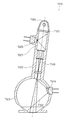
- a seventh embodiment relates to a colorimeter.
- a color meter is a measuring instrument that measures the color of an object.
- FIG. 14 shows a colorimeter of the seventh embodiment.
- the schematic diagram of FIG. 15 shows the measurement mechanism with which the colorimeter of 7th Embodiment is provided.
- the schematic diagram of FIG. 16 shows the light receiving mechanism and controller for reflected light included in the colorimeter of the seventh embodiment.
- the color meter 7000 includes a measurement mechanism 7010 and a controller 7011.
- the measurement mechanism 7010 includes a radiation mechanism 7020, a light beam separation mechanism 7021, an imaging mechanism 7022, an integrating sphere 7023, a light receiving mechanism 7024 for reflected light, and a light receiving mechanism 7025 for reference light.
- the light receiving mechanism 7024 for reflected light includes a color filter group 7030X, a light receiving sensor group 7031X, a color filter group 7030Y, a light receiving sensor group 7031Y, a color filter group 7030Z, and a light receiving sensor group 7031Z, as shown in FIG. As shown in FIG.
- the controller 7011 includes a derivation mechanism 7040X, a derivation mechanism 7040Y, and a derivation mechanism 7040Z.
- Each of the color filter group 7030X, the color filter group 7030Y, and the color filter group 7030Z includes a first color filter 7050 and a second color filter 7051.
- Each of the light receiving sensor group 7031X, the light receiving sensor group 7031Y, and the light receiving sensor group 7031Z includes a first light receiving sensor 7060 and a second light receiving sensor 7061.
- Each of the derivation mechanism 7040X, the derivation mechanism 7040Y, and the derivation mechanism 7040Z includes an amplification mechanism 7070, a conversion mechanism 7071, and an arithmetic mechanism 7072.
- the amplification mechanism 7070 includes a first amplification circuit 7080 and a second amplification circuit 7081.
- the conversion mechanism 7071 includes a first conversion circuit 7090 and a second conversion circuit 7091.
- the radiation mechanism 7020 is a lamp + reflector + diffusion plate or the like, and emits a light beam.
- the light beam separation mechanism 7021 is a half mirror or the like.
- the imaging mechanism 7022 is a lens or the like.
- the emitted light bundle is separated into a light bundle 7100 for illumination light and a light bundle 7101 for reference light by a light bundle separation mechanism 7021.
- the beam bundle 7100 of illumination light is imaged by the imaging mechanism 7022.
- the imaged light bundle 7100 of illumination light illuminates the sample.
- the integrating sphere 7023 functions as a reflection type diffusing member, the measured light bundle 7102 obtained by the sample reflecting the light bundle 7100 of the illumination light is reflected by the integrating sphere 7023 when reflected by the integrating sphere 7023. Diffuse reflected. As a result, the beam bundle 7102 to be measured is branched by the integrating sphere 7023, and beam bundles 7110X, 7111X, 7110Y, 7111Y, 7110Z, and 7111Z are obtained.
- the integrating sphere 7023 which is a spherical diffusing member may be replaced with a non-spherical reflective diffusing member.
- the description of the configuration for obtaining the stimulus value X is the description of the configuration for obtaining the stimulus value Y by replacing “X” and “x” in the description with “Y” and “y”, respectively.
- “X” and “x” in the description are read as “Z” and “z”, respectively, to explain the configuration for obtaining the stimulus value Z.
- the first light bundle 7110X and the second light bundle 7111X are transmitted through the first color filter 7050 and the second color filter 7051 belonging to the color filter group 7030X, respectively.
- the transmitted first light beam 7110X and second light beam 7111X are received by the first light receiving sensor 7060 and the second light receiving sensor 7061 belonging to the light receiving sensor group 7031X, respectively.
- the first light receiving sensor 7060 and the second light receiving sensor 7061 belonging to the light receiving sensor group 7031X respectively receive the first electric signal and the second light signal according to the received first light bundle 7110X and second light bundle 7111X. Outputs electrical signals.
- the deriving mechanism 7040X derives the stimulus value X corresponding to the spectral distribution of the light beam 7102 to be measured from the first electric signal and the second electric signal.
- the first electric signal and the second electric signal are amplified by a first amplifier circuit 7080 and a second amplifier circuit 7081 belonging to the derivation mechanism 7040X, respectively.
- the amplified first electric signal and second electric signal are respectively converted into the first signal value SX1 and the second signal value SX2 by the first conversion circuit 7090 and the second conversion circuit 7091 belonging to the derivation mechanism 7040X.
- the calculation mechanism 7072 belonging to the derivation mechanism 7040X is a microcomputer or the like, and calculates the stimulation value X from the first signal value SX1 and the second signal value SX2.
- the relative spectral response of the colorimeter 6000 with the wavelength error ⁇ 1 of the first color filter 7050 belonging to the color filter group 7030X is performed by the calculation mechanism 7072 or the amplification mechanism 7070 so that the influence on the relative spectral response of the x component of the colorimeter of the wavelength error ⁇ 2 of the second color filter 7051 belonging to the color filter group 7030X is canceled out. Is done. In the color filter group 7030X, the wavelength error ⁇ 1 and the wavelength error ⁇ 2 may be canceled out.
- the deviation from the color matching function of the relative spectral response of the color meter 7000 can be reduced without increasing the production cost of the color meter 7000.
Abstract
Description
1.1 輝度計の相対分光応答度のばらつきの原因
輝度計の相対分光応答度は、輝度計に使用される色フィルターの分光透過率の影響を受ける。このため、色フィルターの分光透過率のばらつきは、輝度計の相対分光応答度のばらつきの原因となる。そこで、輝度計の相対分光応答度のばらつきの原因の理解を容易にするため、色フィルターの分光透過率のばらつきの原因を以下で説明する。 1. Introduction 1.1 Causes of variation in relative spectral response of luminance meters The relative spectral response of luminance meters is affected by the spectral transmittance of color filters used in luminance meters. For this reason, variations in the spectral transmittance of the color filter cause variations in the relative spectral response of the luminance meter. Therefore, in order to facilitate understanding of the cause of the variation in the relative spectral response of the luminance meter, the cause of the variation in the spectral transmittance of the color filter will be described below.
色フィルターが吸収型である場合は、互いに異なる分光透過率を有する複数の色フィルターが重ねあわされ、必要な分光透過率を有する色フィルターの重ねあわせ体が得られる。しかし、色フィルターの分光透過率には、ばらつきがある。このため、色フィルターの重ねあわせ体の分光透過率にも、ばらつきがある。 1.2 Causes of variation in spectral transmittance of absorption type color filters When a color filter is an absorption type, a plurality of color filters having different spectral transmittances are overlapped to obtain a color having a required spectral transmittance. A superposed body of filters is obtained. However, the spectral transmittance of the color filter varies. For this reason, there is also variation in the spectral transmittance of the color filter overlapped body.
色フィルターが干渉型である場合は、ガラス基板上に複数の膜が形成され、必要な分光透過率を有する色フィルターが得られる。 1.3 Causes of variation in spectral transmittance of interference type color filter When the color filter is an interference type, a plurality of films are formed on the glass substrate, and a color filter having a required spectral transmittance is obtained.
複数の膜の各々の膜厚の変化は、色フィルターの分光透過率を複雑に変化させるが、主に色フィルターの分光透過率を波長方向にずれさせる。このため、色フィルターの分光透過率のばらつきは、主に、色フィルターの分光透過率の波長のばらつきとなる。 1.4 Characteristics of variation in spectral transmittance of interference type color filter The change in the film thickness of each of the multiple films changes the spectral transmittance of the color filter in a complex manner. Shift in the wavelength direction. For this reason, the dispersion of the spectral transmittance of the color filter is mainly the dispersion of the wavelength of the spectral transmittance of the color filter.
色フィルターの分光透過率の波長のばらつきの大きさは、成膜装置の能力、大きさ等により変化する。しかし、通常の色フィルターの生産方法が採用された場合は、色フィルターの分光透過率の波長のばらつきの大きさは、バッチ内において概ね±2nmであり、バッチ間において概ね±1nmであり、総合して概ね±3nmである。 1.5 Magnitude of dispersion in wavelength of spectral transmittance of interference type color filter The magnitude of variation in wavelength of spectral transmittance of color filter varies depending on the capability and size of the film forming apparatus. However, when the usual color filter production method is adopted, the variation in wavelength of the spectral transmittance of the color filter is approximately ± 2 nm within the batch and approximately ± 1 nm between the batches. And approximately ± 3 nm.
干渉型の色フィルターは、吸収型の色フィルターと比較して、測定器の相対分光応答度の分光応答度関数からの外れを小さくできる、分光透過率の経時変化が小さい等の利点を有する。外れは、ずれ、偏差等とも呼ばれる。 1.6 Advantages of interference-type color filters Interference-type color filters can reduce the deviation from the spectral response function of the relative spectral response of the measuring instrument compared to the absorption-type color filter. There are advantages such as small change with time. Deviation is also called deviation or deviation.
輝度計に関するドイツ工業規格DIN 5032-7は、輝度計の相対分光応答度S(λ)の国際照明委員会が採用した標準比視感度V(λ)からの外れf1’を式(1)のように定義する。 1.7 Standard for deviation of relative spectral response from spectral response function German Industrial Standard DIN 5032-7 for luminance meter is the standard ratio adopted by the International Commission on Illuminance for Relative Spectral Response S (λ) A deviation f 1 ′ from the visibility V (λ) is defined as shown in Expression (1).

輝度計が生産される場合は、輝度計の相対分光応答度S(λ)の標準比視感度V(λ)からの外れf1’を小さくすることが試みられる。しかし、色フィルターの分光透過率には、ばらつきがある。このため、輝度計の相対分光応答度S(λ)にもばらつきがあり、輝度計の相対分光応答度S(λ)の標準比視感度V(λ)からの外れf1’にもばらつきがある。 1.8 Example of deviation of the relative spectral response of the luminance meter from the standard relative luminous sensitivity When the luminance meter is produced, from the standard relative luminous sensitivity V (λ) of the relative spectral response S (λ) of the luminance meter. An attempt is made to reduce the deviation f 1 ′. However, the spectral transmittance of the color filter varies. For this reason, the relative spectral response S (λ) of the luminance meter also varies, and the deviation f 1 ′ of the relative spectral response S (λ) of the luminance meter from the standard relative luminous sensitivity V (λ) also varies. is there.
通常の生産方法が採用された場合は、干渉型の色フィルターの分光透過率の波長のばらつきの大きさは概ね±3nmである。色フィルターの分光透過率の波長のばらつきの大きさは、概ね、色フィルターにより実現される相対分光応答度の波長のばらつきと同じであるため、色フィルターの分光透過率の波長のばらつきの大きさが概ね±3nmである場合は、色フィルターにより実現される相対分光応答度の波長のばらつきの大きさも概ね±3nmである。しかし、色フィルターにより実現される相対分光応答度の波長のばらつきの大きさが±3nmである場合は、輝度計の等級がB級にさえならない。 1.9 Production of color filter used in luminance meter When the normal production method is adopted, the wavelength variation of the spectral transmittance of the interference type color filter is approximately ± 3 nm. Since the variation in wavelength of the spectral transmittance of the color filter is almost the same as the variation in wavelength of the relative spectral response realized by the color filter, the variation in the wavelength of the spectral transmittance of the color filter is large. Is approximately ± 3 nm, the variation in wavelength of the relative spectral response realized by the color filter is also approximately ± 3 nm. However, when the magnitude of the wavelength variation of the relative spectral response realized by the color filter is ± 3 nm, the luminance meter is not even grade B.
第1実施形態は、輝度計に関する。輝度計は、光源の輝度を測定する測定器である。 2 First Embodiment The first embodiment relates to a luminance meter. A luminance meter is a measuring instrument that measures the luminance of a light source.
図1の模式図は、第1実施形態の輝度計を示す。 2.1 Luminance Meter Hardware The schematic diagram of FIG. 1 shows the luminance meter of the first embodiment.
以下では、色フィルターにより実現される相対分光応答度の重心波長から基準となる最良の色フィルターにより実現される相対分光応答度の重心波長を減じた差を色フィルターの波長誤差Δλとする。 2.2 Suppression of deviation of the relative spectral response of the luminance meter from the standard relative luminous sensitivity The following is the relative spectrum realized by the best color filter as a reference from the barycentric wavelength of the relative spectral response realized by the color filter. The difference obtained by subtracting the centroid wavelength of the response is defined as the wavelength error Δλ of the color filter.
図2のグラフは、波長誤差Δλが-2.1nmである色フィルターにより実現される相対分光応答度及び波長誤差Δλが+1.7nmである色フィルターにより実現される相対分光応答度を示す。図3のグラフは、標準比視感度及び輝度計の相対分光応答度を示す。 2.3 Example of suppression of deviation of relative spectral response of luminance meter from standard relative luminous sensitivity The graph of FIG. 2 shows the relative spectral response and wavelength realized by a color filter having a wavelength error Δλ of −2.1 nm. The relative spectral responsivity realized by the color filter having an error Δλ of +1.7 nm is shown. The graph of FIG. 3 shows the standard relative luminous sensitivity and the relative spectral response of the luminance meter.
図4のフローチャートは、輝度計を生産する方法を示す。 2.4 Method for Producing Luminometer The flowchart of FIG. 4 shows a method for producing a luminance meter.
対物レンズ1010は、測定される光線束1080を結像位置1150に結像させる。視野絞り1011に形成される開口1160は、結像位置1150に配置される。入射端1110は、開口1160から離して配置される。これにより、入射端1110が結像位置1150から離して配置され、光線束1100が焦点を結んでいない状態で入射端1110に入射する。光線束1100が焦点を結んでいない状態で入射端1110に入射する場合は、光線束1100が焦点を結んでいる状態で入射端1110に入射する場合と比較して、入射端1110の径を大きくしなければならない。 2.5 Imaging Position and Bundle Fiber Diameter The
第1実施形態の第1変形例においては、第1の色フィルター1030の波長誤差Δλ1の輝度計1000の相対分光応答度S0(λ)への影響ΔS1(λ)及び第2の色フィルター1031の波長誤差Δλ2の輝度計1000の相対分光応答度S0(λ)への影響ΔS2(λ)が打ち消しあうように、第1の増幅率G1及び第2の増幅率G2を互いに異ならせられる。すなわち、第iの色フィルターの波長誤差Δλiの輝度計1000の相対分光応答度S0(λ)への影響ΔSi(λ)の2個の色フィルター1030及び1031についての集合である影響ΔS1(λ)及び影響ΔS2(λ)が打ち消しあうように、増幅率Giを2個の電気信号(第1の電気信号及び第2の電気信号)の間で異ならせる。 3 First Modification of First Embodiment In the first modification of the first embodiment, the influence ΔS1 of the wavelength error Δλ1 of the
4.1 輝度計の相対分光応答度の標準比視感度からの外れの抑制
第1実施形態の第2変形例においては、第1の色フィルター1030の波長誤差Δλ1及び第2の色フィルター1031の波長誤差Δλ2が打ち消しあう。すなわち、第iの色フィルターの波長誤差Δλiの2個の色フィルター1030及び1031についての集合である波長誤差Δλ1及び波長誤差Δλ2が打ち消しあう。 4 Second Modification of First Embodiment 4.1 Suppression of Relative Spectral Response of Luminometer from Standard Specific Visibility In the second modification of the first embodiment, the wavelength of the

図7のグラフは、波長誤差Δλが-1.2nmである色フィルターにより実現される相対分光応答度及び波長誤差Δλが+0.5nmである色フィルターにより実現される相対分光応答度を示す。図8のグラフは、標準比視感度及び輝度計の相対分光応答度を示す。 4.2 Example of suppression of deviation of relative spectral responsivity of luminance meter from standard relative luminous sensitivity The graph of FIG. 7 shows relative spectral responsivity and wavelength realized by a color filter having a wavelength error Δλ of −1.2 nm. The relative spectral responsivity realized by a color filter with an error Δλ of +0.5 nm is shown. The graph of FIG. 8 shows the standard relative luminous sensitivity and the relative spectral response of the luminance meter.
第2実施形態は、輝度計に関する。 5 Second Embodiment The second embodiment relates to a luminance meter.
図9の模式図は、第2実施形態の輝度計を示す。 5.1 Luminance Meter Hardware The schematic diagram of FIG. 9 shows the luminance meter of the second embodiment.
第2実施形態においては、第1実施形態の第2変形例と同様に、第1の色フィルター2030の波長誤差Δλ1及び第2の色フィルター2031の波長誤差Δλ2が打ち消しあう。このため、第1の電気信号及び第2の電気信号の段階で、第1の色フィルター2030の波長誤差Δλ1の輝度計2000の相対分光応答度S0(λ)への影響ΔS1(λ)及び第2の色フィルター2031の波長誤差Δλ2の輝度計2000の相対分光応答度S0(λ)への影響ΔS2(λ)が既に打ち消し可能になっている。その結果、輝度値LVの段階で、影響ΔS1(λ)及び影響ΔS2(λ)が打ち消しあう。 5.2 Suppression of Deviation of Relative Spectral Response of Standard Luminance Meter from Standard Specific Visibility In the second embodiment, the wavelength error Δλ1 of the
第3実施形態は、輝度計に関する。 6 Third Embodiment The third embodiment relates to a luminance meter.
図10の模式図は、第3実施形態の輝度計を示す。 6.1 Hardware of Luminometer The schematic diagram of FIG. 10 shows the luminance meter of the third embodiment.
第3実施形態においては、第1実施形態の第1変形例と同様に、第1の色フィルター3030の波長誤差Δλ1の輝度計3000の相対分光応答度S0(λ)への影響ΔS1(λ)及び第2の色フィルター3031の波長誤差Δλ2の輝度計3000の相対分光応答度S0(λ)への影響ΔS2(λ)が打ち消しあうように増幅機構3050により重みづけが行われる。このため、増幅された第1の電気信号及び第2の電気信号の段階で、影響ΔS1(λ)及び影響ΔS2(λ)が既に打ち消し可能になっている。その結果、輝度値LVの段階で、影響ΔS1(λ)及び影響ΔS2(λ)が打ち消しあう。 6.2 Inhibition of Relative Spectral Response of Luminance Meter from Standard Specific Visibility In the third embodiment, the wavelength error Δλ1 of the
第4実施形態は、輝度計に関する。 7 Fourth Embodiment The fourth embodiment relates to a luminance meter.
図11の模式図は、第4実施形態の輝度計を示す。 7.1 Luminance Meter Hardware The schematic diagram of FIG. 11 shows the luminance meter of the fourth embodiment.
第4実施形態においては、色フィルター群4013において、第1の色フィルター4030の波長誤差Δλ1、第2の色フィルター4031の波長誤差Δλ2及び第3の色フィルター4032の波長誤差Δλ3が打ち消しあう。すなわち、第iの色フィルターの波長誤差Δλiの3個の色フィルター4030、4031及び4032についての集合である波長誤差Δλ1、波長誤差Δλ2及び波長誤差Δλ3が打ち消しあう。 7.2 Suppression of deviation of relative spectral response of luminance meter from standard relative luminous sensitivity In the fourth embodiment, in the

第5実施形態は、色彩輝度計に関する。色彩輝度計は、光源の色彩及び輝度を測定する測定器である。 8 Fifth Embodiment The fifth embodiment relates to a color luminance meter. A color luminance meter is a measuring instrument that measures the color and luminance of a light source.
図12の模式図は、第5実施形態の色彩輝度計を示す。 8.1 Color Luminometer Hardware The schematic diagram of FIG. 12 shows a color luminance meter of the fifth embodiment.
第5実施形態においては、色フィルター群5013Xに属する第1の色フィルター5030の波長誤差Δλ1Xの色彩輝度計5000の相対分光応答度S0X(λ)への影響ΔS1X(λ)及び色フィルター群5013Xに属する第2の色フィルター5031の波長誤差Δλ2Xの色彩輝度計5000の相対分光応答度S0X(λ)への影響ΔS2X(λ)が打ち消しあうように、演算機構5052又は増幅機構5050により重みづけが行われる。色フィルター群5013Xにおいえ、波長誤差Δλ1X及び波長誤差Δλ2Xが打ち消しあうようにしてもよい。 8.2 Suppression of Relative Spectral Response of Color Luminance Meter from Standard Specific Visibility In the fifth embodiment, the
第6実施形態は、照度計に関する。照度計は、光源の照度を測定する測定器である。 9 Sixth Embodiment The sixth embodiment relates to an illuminometer. An illuminometer is a measuring instrument that measures the illuminance of a light source.
図13の模式図は、第6実施形態の照度計を示す。 9.1 Illuminometer Hardware The schematic diagram of FIG. 13 shows an illuminometer of the sixth embodiment.
第6実施形態においては、第1の色フィルター6030の波長誤差Δλ1の照度計6000の相対分光応答度S0(λ)への影響ΔS1(λ)、第2の色フィルター6031の波長誤差Δλ2の照度計6000の相対分光応答度S0(λ)への影響ΔS2(λ)及び第3の色フィルター6032の波長誤差Δλ3の照度計6000の相対分光応答度S0(λ)への影響ΔS3(λ)が打ち消しあうように、演算機構6052又は増幅機構6050により重みづけが行われる。色フィルター群6012において波長誤差Δλ1、波長誤差Δλ2及び波長誤差Δλ3が打ち消しあうようにしてもよい。 9.2 Suppression of deviation of relative spectral response of illuminometer from standard relative luminous sensitivity In the sixth embodiment, the relative spectral response S0 (λ) of the
第7実施形態は、色彩計に関する。色彩計は、物体の色彩を測定する測定器である。 10 Seventh Embodiment A seventh embodiment relates to a colorimeter. A color meter is a measuring instrument that measures the color of an object.
図14の模式図は、第7実施形態の色彩計を示す。図15の模式図は、第7実施形態の色彩計が備える測定機構を示す。図16の模式図は、第7実施形態の色彩計が備える反射光用の受光機構及びコントローラーを示す。 10.1 Colorimeter Hardware The schematic diagram of FIG. 14 shows a colorimeter of the seventh embodiment. The schematic diagram of FIG. 15 shows the measurement mechanism with which the colorimeter of 7th Embodiment is provided. The schematic diagram of FIG. 16 shows the light receiving mechanism and controller for reflected light included in the colorimeter of the seventh embodiment.
第7実施形態においては、色フィルター群7030Xに属する第1の色フィルター7050の波長誤差Δλ1の色彩計6000の相対分光応答度への影響及び色フィルター群7030Xに属する第2の色フィルター7051の波長誤差Δλ2の色彩計のx成分の相対分光応答度への影響が打ち消しあうように、演算機構7072又は増幅機構7070により重みづけが行われる。色フィルター群7030Xにおいて波長誤差Δλ1及び波長誤差Δλ2が打ち消しあうようにしてもよい。 10.2 Suppression of Relative Spectral Response of Colorimeter from Color Matching Function In the seventh embodiment, the relative spectral response of the
1010 対物レンズ
1011 視野絞り
1012 バンドルファイバー
1013 色フィルター群
1014 受光センサー群
1015 導出機構
1050 増幅機構
1051 変換機構
1052 演算機構
2000 輝度計
2010 対物レンズ
2011 視野絞り
2012 バンドルファイバー
2013 色フィルター群
2014 受光センサー群
2015 導出機構
2050 合流回路
2051 増幅機構
2052 変換機構
2053 演算機構
3000 輝度計
3010 対物レンズ
3011 視野絞り
3012 バンドルファイバー
3013 色フィルター群
3014 受光センサー群
3015 導出機構
3050 増幅機構
3051 合流回路
3052 変換機構
3053 演算機構
4000 輝度計
4010 対物レンズ
4011 視野絞り
4012 バンドルファイバー
4013 色フィルター群
4014 受光センサー群
4015 導出機構
4050 増幅機構
4051 変換機構
4052 演算機構
5000 色彩輝度計
5010 対物レンズ
5011 視野絞り
5012 バンドルファイバー
5013X 色フィルター群
5014X 受光センサー群
5015X 導出機構
5013Y 色フィルター群
5014Y 受光センサー群
5015Y 導出機構
5013Z 色フィルター群
5014Z 受光センサー群
5015Z 導出機構
5050 増幅機構
5051 変換機構
5052 演算機構
6000 照度計
6010 拡散球
6011 拡散板群
6012 色フィルター群
6013 受光センサー群
6014 導出機構
6050 増幅機構
6051 変換機構
6052 演算機構
7000 色彩計
7010 測定機構
7011 コントローラー
7020 放射機構
7021 光線束分離機構
7022 結像機構
7023 積分球
7024 反射光用の受光機構
7025 参照光用の受光機構
7030X 色フィルター群
7031X 受光センサー群
7030Y 色フィルター群
7031Y 受光センサー群
7030Z 色フィルター群
7031Z 受光センサー群
7040X 導出機構
7040Y 導出機構
7040Z 導出機構
7070 増幅機構
7071 変換機構
7072 演算機構 1000 Luminometer 1010 Objective lens 1011 Field stop 1012 Bundle fiber 1013 Color filter group 1014 Light sensor group 1015 Derivation mechanism 1050 Amplification mechanism 1051 Conversion mechanism 1052 Calculation mechanism 2000 Luminance meter 2010 Objective lens 2011 Field stop 2012 Bundle fiber 2013 Color filter group 2014 Light reception Sensor group 2015 Deriving mechanism 2050 Junction circuit 2051 Amplifying mechanism 2052 Conversion mechanism 2053 Arithmetic mechanism 3000 Luminance meter 3010 Objective lens 3011 Field stop 3012 Bundle fiber 3013 Color filter group 3014 Light receiving sensor group 3015 Deriving mechanism 3050 Amplifying mechanism 3051 Converging circuit 3053 Conversion mechanism 3053 Arithmetic mechanism 4000 Luminance meter 4010 Objective lens 4011 Aperture 4012 Bundle fiber 4013 Color filter group 4014 Light receiving sensor group 4015 Deriving mechanism 4050 Amplifying mechanism 4051 Conversion mechanism 4052 Arithmetic mechanism 5000 Color luminance meter 5010 Objective lens 5011 Field stop 5012 Bundle fiber 5013X Color filter group 5014X Light receiving sensor group 5015Y Coloring mechanism 5013Y Filter group 5014Y Light receiving sensor group 5015Y Deriving mechanism 5013Z Color filter group 5014Z Light receiving sensor group 5015Z Deriving mechanism 5050 Amplifying mechanism 5051 Conversion mechanism 5052 Arithmetic mechanism 6000 Illuminometer 6010 Diffusion sphere 6011 Diffusion plate group 6012 Color filter group 6013 Light receiving sensor group 6014 Deriving mechanism 6050 Amplification mechanism 6051 Conversion mechanism 6052 Calculation mechanism 7000 Colorimeter 7010 Measurement mechanism 7011 Controller 7020 Radiation mechanism 7021 Ray bundle separation mechanism 7022 Imaging mechanism 7023 Integrating sphere 7024 Light reception mechanism for reflected light 7025 Light reception mechanism for reference light 7030X Color filter group 7031X Light reception sensor group 7030Y Color filter group 7031Y Light reception Sensor group 7030Z Color filter group 7031Z Light receiving sensor group 7040X Deriving mechanism 7040Y Deriving mechanism 7040Z Deriving mechanism 7070 Amplifying mechanism 7071 Conversion mechanism 7072 Computing mechanism
Claims (18)
- 測定される光線束を分岐させることにより複数の光線束を得る分岐機構と、
前記複数の光線束の各々を透過させる複数の色フィルターを備え、前記複数の色フィルターの各々により実現される相対分光応答度が分光応答度関数に近似させられる色フィルター群と、
前記複数の色フィルターの各々を透過した光線束を受光する複数の受光センサーを備え、受光した光線束に応じた電気信号を前記複数の受光センサーの各々が出力することにより複数の電気信号を出力する受光センサー群と、
測定される光線束の分光分布に応じた測定値を前記複数の電気信号から導出する導出機構と、
を備える測定器。 A branching mechanism that obtains a plurality of light bundles by branching the light bundle to be measured;
A plurality of color filters that transmit each of the plurality of light bundles, and a color filter group in which a relative spectral response realized by each of the plurality of color filters is approximated to a spectral response function;
Provided with a plurality of light receiving sensors for receiving a light bundle transmitted through each of the plurality of color filters, each of the plurality of light receiving sensors outputs a plurality of electrical signals according to the received light bundle. A group of light receiving sensors to
A derivation mechanism for deriving a measurement value corresponding to the spectral distribution of the measured light bundle from the plurality of electrical signals;
Measuring instrument. - 前記複数の色フィルターの各々が干渉型であり、
前記導出機構は、一の色フィルターにより実現される相対分光応答度の基準となる相対分光応答度からの波長ずれを一の色フィルターの波長ずれとした場合に、一の色フィルターの波長ずれの相対分光応答度への影響の前記複数の色フィルターについての集合が打ち消しあうように一の電気信号の前記測定値への寄与の大きさを前記複数の電気信号の間で異ならせる重みづけを行う
請求項1の測定器。 Each of the plurality of color filters is an interference type,
The derivation mechanism determines the wavelength shift of one color filter when the wavelength shift from the relative spectral response that is a reference of the relative spectral response realized by the one color filter is the wavelength shift of the one color filter. Weighting is performed so that the magnitude of the contribution of one electrical signal to the measurement value differs among the plurality of electrical signals so that the set of the plurality of color filters with respect to the influence on relative spectral response cancels each other. The measuring instrument according to claim 1. - 前記導出機構は、
前記複数の電気信号の各々を信号値に変換することにより複数の信号値を得る変換機構と、
前記複数の信号値から前記測定値を演算し、一の信号値に乗じられる重みづけ係数を前記複数の信号値の間で異ならせることにより重みづけを行う演算機構と、
を備える
請求項2の測定器。 The derivation mechanism is
A conversion mechanism for obtaining a plurality of signal values by converting each of the plurality of electrical signals into a signal value;
An arithmetic mechanism that calculates the measurement value from the plurality of signal values and performs weighting by making a weighting coefficient to be multiplied by one signal value different between the plurality of signal values;
The measuring device according to claim 2. - 一の色フィルターにより実現される相対分光応答度の特徴波長から前記基準となる相対分光応答度の特徴波長を減じた差を一の色フィルターの波長誤差とした場合に、一の色フィルターを透過した光線束を受光する受光センサーが出力する電気信号を変換して得られる信号値に乗じられる重みづけ係数を一の色フィルターの波長誤差に乗じた積の前記複数の色フィルターについての集合が打ち消しあう
請求項3の測定器。 When the difference between the characteristic wavelength of the relative spectral response realized by one color filter and the characteristic wavelength of the reference relative spectral response is the wavelength error of the one color filter, it passes through the one color filter. The set of the plurality of color filters cancels a product obtained by multiplying the wavelength error of one color filter by a weighting coefficient multiplied by a signal value obtained by converting an electric signal output from a light receiving sensor that receives the light beam. The measuring device according to claim 3. - 前記導出機構は、
前記複数の電気信号の各々を増幅することにより複数の増幅された電気信号を得、一の電気信号を増幅する場合の増幅率を前記複数の電気信号の間で異ならせることにより重みづけを行う増幅機構と、
前記複数の増幅された電気信号の各々を信号値に変換することにより複数の信号値を得る変換機構と、
前記複数の信号値から前記測定値を演算する演算機構と、
を備える
請求項2の測定器。 The derivation mechanism is
Each of the plurality of electrical signals is amplified to obtain a plurality of amplified electrical signals, and weighting is performed by differentiating the amplification factor between the plurality of electrical signals when a single electrical signal is amplified. An amplification mechanism;
A conversion mechanism for obtaining a plurality of signal values by converting each of the plurality of amplified electrical signals into a signal value;
A calculation mechanism for calculating the measurement value from the plurality of signal values;
The measuring device according to claim 2. - 前記導出機構は、
前記複数の電気信号の各々を増幅することにより複数の増幅された電気信号を得、一の電気信号を増幅する場合の増幅率を前記複数の電気信号の間で異ならせることにより重みづけを行う増幅機構と、
前記複数の増幅された電気信号を合流させることにより合流後の電気信号を得る合流回路と、
前記合流後の電気信号を信号値に変換する変換機構と、
前記信号値から前記測定値を演算する演算機構と、
を備える
請求項2の測定器。 The derivation mechanism is
Each of the plurality of electrical signals is amplified to obtain a plurality of amplified electrical signals, and weighting is performed by differentiating the amplification factor between the plurality of electrical signals when a single electrical signal is amplified. An amplification mechanism;
A merging circuit that obtains an electric signal after merging by merging the plurality of amplified electric signals;
A conversion mechanism for converting the combined electrical signal into a signal value;
A calculation mechanism for calculating the measured value from the signal value;
The measuring device according to claim 2. - 一の色フィルターにより実現される相対分光応答度の特徴波長から前記基準となる相対分光応答度の特徴波長を減じた差を一の色フィルターの波長誤差とした場合に、一の色フィルターを透過した光線束を受光する受光センサーが出力する電気信号を増幅する場合の増幅率を一の色フィルターの波長誤差に乗じた積の前記複数の色フィルターについての集合が打ち消しあう
請求項5又は6の測定器。 When the difference between the characteristic wavelength of the relative spectral response realized by one color filter and the characteristic wavelength of the reference relative spectral response is the wavelength error of the one color filter, it passes through the one color filter. 7. The set of the plurality of color filters of products obtained by multiplying an amplification factor in the case of amplifying an electric signal output from a light receiving sensor that receives the light bundle, multiplied by a wavelength error of one color filter, cancels each other. Measuring instrument. - 前記複数の色フィルターの各々が干渉型であり、
一の色フィルターにより実現される相対分光応答度の基準となる相対分光応答度からの波長ずれの前記複数の色フィルターについての集合が打ち消しあう
請求項1の測定器。 Each of the plurality of color filters is an interference type,
The measuring device according to claim 1, wherein a set of the plurality of color filters having a wavelength shift from a relative spectral response serving as a reference of the relative spectral response realized by one color filter cancels each other. - 一の色フィルターにより実現される相対分光応答度の特徴波長から前記基準となる相対分光応答度の特徴波長を減じた差を一の色フィルターの波長誤差とした場合に、一の色フィルターの波長誤差の前記複数の色フィルターについての集合が打ち消しあう
請求項8の測定器。 Wavelength of one color filter when the difference between the characteristic wavelength of relative spectral response realized by one color filter and the characteristic wavelength of relative spectral response serving as the reference is the wavelength error of one color filter. 9. The measuring device of claim 8, wherein the set of errors for the plurality of color filters cancels each other. - 前記導出機構は、
前記複数の電気信号の各々を信号値に変換することにより複数の信号値を得る変換機構と、
前記複数の信号値から前記測定値を演算する演算機構と、
を備える
請求項8又は9の測定器。 The derivation mechanism is
A conversion mechanism for obtaining a plurality of signal values by converting each of the plurality of electrical signals into a signal value;
A calculation mechanism for calculating the measurement value from the plurality of signal values;
A measuring instrument according to claim 8 or 9. - 前記導出機構は、
前記複数の電気信号を合流させることにより合流後の電気信号を得る合流回路と、
前記合流後の電気信号を信号値に変換する変換機構と、
前記信号値から前記測定値を演算する演算機構と、
を備える
請求項8又は9の測定器。 The derivation mechanism is
A merging circuit for obtaining an electric signal after merging by merging the plurality of electric signals;
A conversion mechanism for converting the combined electrical signal into a signal value;
A calculation mechanism for calculating the measured value from the signal value;
A measuring instrument according to claim 8 or 9. - 前記特徴波長が重心波長、ピーク波長又は半値波長である
請求項4、7又は9の測定器。 The measuring device according to claim 4, 7 or 9, wherein the characteristic wavelength is a center of gravity wavelength, a peak wavelength, or a half-value wavelength. - 測定される光線束を結像位置に結像させる対物光学系
をさらに備え、
前記分岐機構がバンドルファイバーであり、
前記バンドルファイバーが、測定される光線束が入射する入射端を有し、前記複数の光線束の各々が出射する複数の出射端を有し、
前記入射端が前記結像位置から離れて配置され、
前記複数の光線束の各々の全体が前記色フィルターを透過し前記色フィルターを透過した光線束の全体が前記受光センサーに受光される
請求項1から12までのいずれかの測定器。 An objective optical system for forming an image of the light beam to be measured at the imaging position;
The branching mechanism is a bundle fiber;
The bundle fiber has an incident end on which a light bundle to be measured is incident, and has a plurality of exit ends from which each of the plurality of light bundles is emitted,
The incident end is disposed away from the imaging position;
The measuring instrument according to any one of claims 1 to 12, wherein each of the plurality of light bundles is transmitted through the color filter, and the entire light bundle transmitted through the color filter is received by the light receiving sensor. - 前記分岐機構が、測定される光線束を透過させ、透過した光線束を拡散することにより前記複数の光線束を得る透過型の拡散部材である
請求項1から12までのいずれかの測定器。 The measuring device according to any one of claims 1 to 12, wherein the branching mechanism is a transmission type diffusing member that transmits the light bundle to be measured and diffuses the transmitted light bundle to obtain the plurality of light bundles. - 前記分岐機構が、測定される光線束を反射し、反射した光線束を拡散することにより前記複数の光線束を得る反射型の拡散部材である
請求項1から12までのいずれかの測定器。 The measuring device according to any one of claims 1 to 12, wherein the branching mechanism is a reflection type diffusing member that reflects the light beam to be measured and diffuses the reflected light beam to obtain the plurality of light beams. - 前記分光応答度関数が標準比視感度である
請求項1から15までのいずれかの測定器。 The measuring instrument according to any one of claims 1 to 15, wherein the spectral response function is a standard relative luminous sensitivity. - 前記複数の光線束が第1の複数の光線束であり、
前記分岐機構が第2の複数の光線束及び第3の複数の光線束をさらに得、
前記色フィルターが第1の色フィルターであり、
前記複数の色フィルターが第1の複数の色フィルターであり、
前記分光応答度関数が等色関数のx成分であり、
前記色フィルター群が第1の色フィルター群であり、
前記受光センサーが第1の受光センサーであり、
前記複数の受光センサーが第1の複数の受光センサーであり、
前記受光センサー群が第1の受光センサー群であり、
前記電気信号が第1の電気信号であり、
前記複数の電気信号が第1の複数の電気信号であり、
前記測定値が刺激値Xであり、
前記導出機構が第1の導出機構であり、
前記第2の複数の光線束の各々を透過させる第2の複数の色フィルターを備え、前記第2の複数の色フィルターの各々により実現される相対分光応答度が等色関数のy成分に近似させられる第2の色フィルター群と、
前記第2の複数の色フィルターの各々を透過した光線束を受光する第2の複数の受光センサーを備え、受光した光線束に応じた第2の電気信号を前記第2の複数の受光センサーの各々が出力することにより第2の複数の電気信号を出力する第2の受光センサー群と、
測定される光線束の分光分布に応じた刺激値Yを前記第2の複数の電気信号から導出する第2の導出機構と、
前記第3の複数の光線束の各々を透過させる第3の複数の色フィルターを備え、前記第3の複数の色フィルターの各々により実現される相対分光応答度が等色関数のz成分に近似させられる第3の色フィルター群と、
前記第3の複数の色フィルターの各々を透過した光線束を受光する第3の複数の受光センサーを備え、受光した光線束に応じた第3の電気信号を前記第3の複数の受光センサーの各々が出力することにより第3の複数の電気信号を出力する第3の受光センサー群と、
測定される光線束の分光分布に応じた刺激値Zを前記第3の複数の電気信号から導出する第3の導出機構と、
をさらに備える請求項1から16までのいずれかの測定器。 The plurality of light bundles is a first plurality of light bundles;
The branching mechanism further obtains a second plurality of light bundles and a third plurality of light bundles;
The color filter is a first color filter;
The plurality of color filters is a first plurality of color filters;
The spectral response function is an x component of a color matching function;
The color filter group is a first color filter group;
The light receiving sensor is a first light receiving sensor;
The plurality of light receiving sensors is a first plurality of light receiving sensors;
The light receiving sensor group is a first light receiving sensor group;
The electrical signal is a first electrical signal;
The plurality of electrical signals is a first plurality of electrical signals;
The measured value is the stimulus value X;
The derivation mechanism is a first derivation mechanism;
A second plurality of color filters that transmit each of the second plurality of light bundles, and a relative spectral response realized by each of the second plurality of color filters approximates a y component of a color matching function A second color filter group,
A second plurality of light receiving sensors for receiving a light bundle transmitted through each of the second plurality of color filters; and a second electric signal corresponding to the received light bundle is transmitted to the second plurality of light receiving sensors. A second light receiving sensor group that outputs a second plurality of electrical signals by each outputting;
A second derivation mechanism for deriving a stimulus value Y corresponding to the spectral distribution of the light bundle to be measured from the second plurality of electrical signals;
A third plurality of color filters that transmit each of the third plurality of light bundles, and a relative spectral response realized by each of the third plurality of color filters approximates a z component of a color matching function A third color filter group,
A third plurality of light receiving sensors for receiving the light bundle transmitted through each of the third plurality of color filters, and a third electrical signal corresponding to the received light bundle is sent to the third plurality of light receiving sensors; A third light receiving sensor group that outputs a third plurality of electrical signals by each output;
A third derivation mechanism for deriving a stimulus value Z corresponding to the spectral distribution of the light bundle to be measured from the third plurality of electrical signals;
The measuring instrument according to any one of claims 1 to 16, further comprising: - 請求項1の測定器が備える複数の色フィルターの候補となる色フィルターを準備する工程と、
準備された色フィルターの各々の相対分光応答度の基準となる相対分光応答度からの波長ずれを測定する工程と、
請求項1の測定器が備える複数の色フィルターの各々に適した波長ずれを有する色フィルターを準備された色フィルターから選択することにより請求項1の測定器が備える複数の色フィルターとして使用される複数の色フィルターを選択する工程と、
選択された複数の色フィルターを請求項1の測定器が備える複数の色フィルターとして使用して請求項1の測定器を組み立てる工程と、
を備える測定器を生産する方法。 Preparing a color filter that is a candidate for a plurality of color filters provided in the measuring device of claim 1;
Measuring a wavelength shift from a relative spectral response serving as a reference for the relative spectral response of each of the prepared color filters;
The color filter having a wavelength shift suitable for each of the plurality of color filters provided in the measuring device of claim 1 is selected from the prepared color filters, and used as the plurality of color filters provided in the measuring device of claim 1. Selecting a plurality of color filters;
Assembling the measuring device of claim 1 using the selected plurality of color filters as a plurality of color filters included in the measuring device of claim 1;
A method for producing a measuring instrument comprising:
Priority Applications (2)
| Application Number | Priority Date | Filing Date | Title |
|---|---|---|---|
| JP2017525247A JP6794986B2 (en) | 2015-06-24 | 2016-06-15 | Measuring instruments and methods of producing measuring instruments |
| DE112016002826.1T DE112016002826T5 (en) | 2015-06-24 | 2016-06-15 | Meter and method of making the meter |
Applications Claiming Priority (2)
| Application Number | Priority Date | Filing Date | Title |
|---|---|---|---|
| JP2015-126595 | 2015-06-24 | ||
| JP2015126595 | 2015-06-24 |
Publications (1)
| Publication Number | Publication Date |
|---|---|
| WO2016208462A1 true WO2016208462A1 (en) | 2016-12-29 |
Family
ID=57585040
Family Applications (1)
| Application Number | Title | Priority Date | Filing Date |
|---|---|---|---|
| PCT/JP2016/067712 WO2016208462A1 (en) | 2015-06-24 | 2016-06-15 | Measureing device and method of manufacturing measureing device |
Country Status (3)
| Country | Link |
|---|---|
| JP (1) | JP6794986B2 (en) |
| DE (1) | DE112016002826T5 (en) |
| WO (1) | WO2016208462A1 (en) |
Citations (9)
| Publication number | Priority date | Publication date | Assignee | Title |
|---|---|---|---|---|
| JPS57204427A (en) * | 1981-06-11 | 1982-12-15 | Omron Tateisi Electronics Co | Color discriminating element of 3 primary color separation |
| JPS63154920A (en) * | 1986-12-19 | 1988-06-28 | Matsushita Electric Ind Co Ltd | Light receiving part of illuminometer |
| JPH0245718A (en) * | 1988-08-05 | 1990-02-15 | Minolta Camera Co Ltd | Spectral sensitivity correction mechanism for photoelectric colorimeter |
| JPH04113235A (en) * | 1990-09-04 | 1992-04-14 | Minolta Camera Co Ltd | Photosensor |
| US5149182A (en) * | 1991-05-02 | 1992-09-22 | Tektronix, Inc. | Optical filter for an optical measurement instrument |
| JPH05281021A (en) * | 1992-03-30 | 1993-10-29 | Horiba Ltd | Sensitivity evaluation method for thermal detector |
| JP2010139446A (en) * | 2008-12-12 | 2010-06-24 | Hioki Ee Corp | Integrating sphere and photometer |
| JP2011107114A (en) * | 2009-10-20 | 2011-06-02 | Hioki Ee Corp | Photometric device |
| WO2011121896A1 (en) * | 2010-03-31 | 2011-10-06 | コニカミノルタセンシング株式会社 | Optical system for measurement, and color luminance meter and colorimeter using the same |
-
2016
- 2016-06-15 WO PCT/JP2016/067712 patent/WO2016208462A1/en active Application Filing
- 2016-06-15 DE DE112016002826.1T patent/DE112016002826T5/en active Pending
- 2016-06-15 JP JP2017525247A patent/JP6794986B2/en active Active
Patent Citations (9)
| Publication number | Priority date | Publication date | Assignee | Title |
|---|---|---|---|---|
| JPS57204427A (en) * | 1981-06-11 | 1982-12-15 | Omron Tateisi Electronics Co | Color discriminating element of 3 primary color separation |
| JPS63154920A (en) * | 1986-12-19 | 1988-06-28 | Matsushita Electric Ind Co Ltd | Light receiving part of illuminometer |
| JPH0245718A (en) * | 1988-08-05 | 1990-02-15 | Minolta Camera Co Ltd | Spectral sensitivity correction mechanism for photoelectric colorimeter |
| JPH04113235A (en) * | 1990-09-04 | 1992-04-14 | Minolta Camera Co Ltd | Photosensor |
| US5149182A (en) * | 1991-05-02 | 1992-09-22 | Tektronix, Inc. | Optical filter for an optical measurement instrument |
| JPH05281021A (en) * | 1992-03-30 | 1993-10-29 | Horiba Ltd | Sensitivity evaluation method for thermal detector |
| JP2010139446A (en) * | 2008-12-12 | 2010-06-24 | Hioki Ee Corp | Integrating sphere and photometer |
| JP2011107114A (en) * | 2009-10-20 | 2011-06-02 | Hioki Ee Corp | Photometric device |
| WO2011121896A1 (en) * | 2010-03-31 | 2011-10-06 | コニカミノルタセンシング株式会社 | Optical system for measurement, and color luminance meter and colorimeter using the same |
Also Published As
| Publication number | Publication date |
|---|---|
| JP6794986B2 (en) | 2020-12-02 |
| DE112016002826T5 (en) | 2018-03-08 |
| JPWO2016208462A1 (en) | 2018-04-12 |
Similar Documents
| Publication | Publication Date | Title |
|---|---|---|
| CN101276826B (en) | Light sensor, manufacturing method thereof and method for generating light intensity estimate value by using the same | |
| JP3284997B2 (en) | Optical system for measurement | |
| CN101782428A (en) | Spectrum self-correction photometer and measuring method thereof | |
| CN111413070A (en) | Brightness detection device and detection method thereof | |
| JP5683834B2 (en) | Photometric device | |
| US4776702A (en) | Device for color distinction | |
| JP2010025558A (en) | Optical system for measurement | |
| JP2002013981A (en) | Photometer | |
| CN105241640A (en) | Device for measuring blue light weighted radiation intensity and method thereof | |
| JP2010133833A (en) | Photometric device | |
| Mahmoud et al. | Measurement of normalized spectral responsivity of digital imaging devices by using a LED-based tunable uniform source | |
| WO2016208462A1 (en) | Measureing device and method of manufacturing measureing device | |
| CN111649830A (en) | Radiation spectrum-based color CCD self-calibration temperature measuring device and method | |
| JP2009532666A (en) | Spectroscopic measurement system and method for compensating false light | |
| KR20070092577A (en) | An optical sensing system and a color analyzer with the optical sensing system | |
| KR101239573B1 (en) | Photometer | |
| CN212133888U (en) | Color CCD self-calibration temperature measuring device based on radiation spectrum | |
| CN201503310U (en) | Optical system of novel color luminance meter | |
| US20190063995A1 (en) | Color parameter measurement device and color parameter measurement method | |
| JP6692614B2 (en) | Measuring instrument | |
| Mao et al. | A 3-channel CCD photometer at the Xinglong Observatory | |
| CN212459386U (en) | Optical measuring instrument | |
| Ghinassi et al. | Transmission curves and effective refraction indices of MKO near infrared consortium filters at cryogenic temperatures | |
| JP7286014B2 (en) | High-sensitivity non-contact chromaticity measuring device | |
| WO2024085027A1 (en) | Optical device for measurement |
Legal Events
| Date | Code | Title | Description |
|---|---|---|---|
| 121 | Ep: the epo has been informed by wipo that ep was designated in this application |
Ref document number: 16814233 Country of ref document: EP Kind code of ref document: A1 |
|
| ENP | Entry into the national phase |
Ref document number: 2017525247 Country of ref document: JP Kind code of ref document: A |
|
| WWE | Wipo information: entry into national phase |
Ref document number: 112016002826 Country of ref document: DE |
|
| 122 | Ep: pct application non-entry in european phase |
Ref document number: 16814233 Country of ref document: EP Kind code of ref document: A1 |