WO2016208361A1 - 蓄電装置 - Google Patents
蓄電装置 Download PDFInfo
- Publication number
- WO2016208361A1 WO2016208361A1 PCT/JP2016/066532 JP2016066532W WO2016208361A1 WO 2016208361 A1 WO2016208361 A1 WO 2016208361A1 JP 2016066532 W JP2016066532 W JP 2016066532W WO 2016208361 A1 WO2016208361 A1 WO 2016208361A1
- Authority
- WO
- WIPO (PCT)
- Prior art keywords
- power storage
- duct
- disposed
- element group
- storage elements
- Prior art date
- Legal status (The legal status is an assumption and is not a legal conclusion. Google has not performed a legal analysis and makes no representation as to the accuracy of the status listed.)
- Ceased
Links
Images






Classifications
-
- H—ELECTRICITY
- H01—ELECTRIC ELEMENTS
- H01G—CAPACITORS; CAPACITORS, RECTIFIERS, DETECTORS, SWITCHING DEVICES, LIGHT-SENSITIVE OR TEMPERATURE-SENSITIVE DEVICES OF THE ELECTROLYTIC TYPE
- H01G2/00—Details of capacitors not covered by a single one of groups H01G4/00-H01G11/00
- H01G2/02—Mountings
- H01G2/04—Mountings specially adapted for mounting on a chassis
-
- H—ELECTRICITY
- H01—ELECTRIC ELEMENTS
- H01G—CAPACITORS; CAPACITORS, RECTIFIERS, DETECTORS, SWITCHING DEVICES, LIGHT-SENSITIVE OR TEMPERATURE-SENSITIVE DEVICES OF THE ELECTROLYTIC TYPE
- H01G11/00—Hybrid capacitors, i.e. capacitors having different positive and negative electrodes; Electric double-layer [EDL] capacitors; Processes for the manufacture thereof or of parts thereof
- H01G11/10—Multiple hybrid or EDL capacitors, e.g. arrays or modules
-
- H—ELECTRICITY
- H01—ELECTRIC ELEMENTS
- H01G—CAPACITORS; CAPACITORS, RECTIFIERS, DETECTORS, SWITCHING DEVICES, LIGHT-SENSITIVE OR TEMPERATURE-SENSITIVE DEVICES OF THE ELECTROLYTIC TYPE
- H01G11/00—Hybrid capacitors, i.e. capacitors having different positive and negative electrodes; Electric double-layer [EDL] capacitors; Processes for the manufacture thereof or of parts thereof
- H01G11/14—Arrangements or processes for adjusting or protecting hybrid or EDL capacitors
- H01G11/18—Arrangements or processes for adjusting or protecting hybrid or EDL capacitors against thermal overloads, e.g. heating, cooling or ventilating
-
- H—ELECTRICITY
- H01—ELECTRIC ELEMENTS
- H01G—CAPACITORS; CAPACITORS, RECTIFIERS, DETECTORS, SWITCHING DEVICES, LIGHT-SENSITIVE OR TEMPERATURE-SENSITIVE DEVICES OF THE ELECTROLYTIC TYPE
- H01G2/00—Details of capacitors not covered by a single one of groups H01G4/00-H01G11/00
- H01G2/08—Cooling arrangements; Heating arrangements; Ventilating arrangements
-
- H—ELECTRICITY
- H01—ELECTRIC ELEMENTS
- H01M—PROCESSES OR MEANS, e.g. BATTERIES, FOR THE DIRECT CONVERSION OF CHEMICAL ENERGY INTO ELECTRICAL ENERGY
- H01M10/00—Secondary cells; Manufacture thereof
- H01M10/60—Heating or cooling; Temperature control
- H01M10/61—Types of temperature control
- H01M10/613—Cooling or keeping cold
-
- H—ELECTRICITY
- H01—ELECTRIC ELEMENTS
- H01M—PROCESSES OR MEANS, e.g. BATTERIES, FOR THE DIRECT CONVERSION OF CHEMICAL ENERGY INTO ELECTRICAL ENERGY
- H01M10/00—Secondary cells; Manufacture thereof
- H01M10/60—Heating or cooling; Temperature control
- H01M10/62—Heating or cooling; Temperature control specially adapted for specific applications
- H01M10/625—Vehicles
-
- H—ELECTRICITY
- H01—ELECTRIC ELEMENTS
- H01M—PROCESSES OR MEANS, e.g. BATTERIES, FOR THE DIRECT CONVERSION OF CHEMICAL ENERGY INTO ELECTRICAL ENERGY
- H01M10/00—Secondary cells; Manufacture thereof
- H01M10/60—Heating or cooling; Temperature control
- H01M10/64—Heating or cooling; Temperature control characterised by the shape of the cells
- H01M10/643—Cylindrical cells
-
- H—ELECTRICITY
- H01—ELECTRIC ELEMENTS
- H01M—PROCESSES OR MEANS, e.g. BATTERIES, FOR THE DIRECT CONVERSION OF CHEMICAL ENERGY INTO ELECTRICAL ENERGY
- H01M10/00—Secondary cells; Manufacture thereof
- H01M10/60—Heating or cooling; Temperature control
- H01M10/64—Heating or cooling; Temperature control characterised by the shape of the cells
- H01M10/647—Prismatic or flat cells, e.g. pouch cells
-
- H—ELECTRICITY
- H01—ELECTRIC ELEMENTS
- H01M—PROCESSES OR MEANS, e.g. BATTERIES, FOR THE DIRECT CONVERSION OF CHEMICAL ENERGY INTO ELECTRICAL ENERGY
- H01M10/00—Secondary cells; Manufacture thereof
- H01M10/60—Heating or cooling; Temperature control
- H01M10/65—Means for temperature control structurally associated with the cells
- H01M10/651—Means for temperature control structurally associated with the cells characterised by parameters specified by a numeric value or mathematical formula, e.g. ratios, sizes or concentrations
-
- H—ELECTRICITY
- H01—ELECTRIC ELEMENTS
- H01M—PROCESSES OR MEANS, e.g. BATTERIES, FOR THE DIRECT CONVERSION OF CHEMICAL ENERGY INTO ELECTRICAL ENERGY
- H01M10/00—Secondary cells; Manufacture thereof
- H01M10/60—Heating or cooling; Temperature control
- H01M10/65—Means for temperature control structurally associated with the cells
- H01M10/655—Solid structures for heat exchange or heat conduction
- H01M10/6556—Solid parts with flow channel passages or pipes for heat exchange
-
- H—ELECTRICITY
- H01—ELECTRIC ELEMENTS
- H01M—PROCESSES OR MEANS, e.g. BATTERIES, FOR THE DIRECT CONVERSION OF CHEMICAL ENERGY INTO ELECTRICAL ENERGY
- H01M10/00—Secondary cells; Manufacture thereof
- H01M10/60—Heating or cooling; Temperature control
- H01M10/65—Means for temperature control structurally associated with the cells
- H01M10/656—Means for temperature control structurally associated with the cells characterised by the type of heat-exchange fluid
- H01M10/6561—Gases
- H01M10/6563—Gases with forced flow, e.g. by blowers
-
- H—ELECTRICITY
- H01—ELECTRIC ELEMENTS
- H01M—PROCESSES OR MEANS, e.g. BATTERIES, FOR THE DIRECT CONVERSION OF CHEMICAL ENERGY INTO ELECTRICAL ENERGY
- H01M50/00—Constructional details or processes of manufacture of the non-active parts of electrochemical cells other than fuel cells, e.g. hybrid cells
- H01M50/20—Mountings; Secondary casings or frames; Racks, modules or packs; Suspension devices; Shock absorbers; Transport or carrying devices; Holders
- H01M50/204—Racks, modules or packs for multiple batteries or multiple cells
- H01M50/207—Racks, modules or packs for multiple batteries or multiple cells characterised by their shape
- H01M50/213—Racks, modules or packs for multiple batteries or multiple cells characterised by their shape adapted for cells having curved cross-section, e.g. round or elliptic
-
- H—ELECTRICITY
- H01—ELECTRIC ELEMENTS
- H01M—PROCESSES OR MEANS, e.g. BATTERIES, FOR THE DIRECT CONVERSION OF CHEMICAL ENERGY INTO ELECTRICAL ENERGY
- H01M50/00—Constructional details or processes of manufacture of the non-active parts of electrochemical cells other than fuel cells, e.g. hybrid cells
- H01M50/20—Mountings; Secondary casings or frames; Racks, modules or packs; Suspension devices; Shock absorbers; Transport or carrying devices; Holders
- H01M50/218—Mountings; Secondary casings or frames; Racks, modules or packs; Suspension devices; Shock absorbers; Transport or carrying devices; Holders characterised by the material
- H01M50/22—Mountings; Secondary casings or frames; Racks, modules or packs; Suspension devices; Shock absorbers; Transport or carrying devices; Holders characterised by the material of the casings or racks
- H01M50/227—Organic material
-
- H—ELECTRICITY
- H01—ELECTRIC ELEMENTS
- H01M—PROCESSES OR MEANS, e.g. BATTERIES, FOR THE DIRECT CONVERSION OF CHEMICAL ENERGY INTO ELECTRICAL ENERGY
- H01M50/00—Constructional details or processes of manufacture of the non-active parts of electrochemical cells other than fuel cells, e.g. hybrid cells
- H01M50/20—Mountings; Secondary casings or frames; Racks, modules or packs; Suspension devices; Shock absorbers; Transport or carrying devices; Holders
- H01M50/271—Lids or covers for the racks or secondary casings
-
- Y—GENERAL TAGGING OF NEW TECHNOLOGICAL DEVELOPMENTS; GENERAL TAGGING OF CROSS-SECTIONAL TECHNOLOGIES SPANNING OVER SEVERAL SECTIONS OF THE IPC; TECHNICAL SUBJECTS COVERED BY FORMER USPC CROSS-REFERENCE ART COLLECTIONS [XRACs] AND DIGESTS
- Y02—TECHNOLOGIES OR APPLICATIONS FOR MITIGATION OR ADAPTATION AGAINST CLIMATE CHANGE
- Y02E—REDUCTION OF GREENHOUSE GAS [GHG] EMISSIONS, RELATED TO ENERGY GENERATION, TRANSMISSION OR DISTRIBUTION
- Y02E60/00—Enabling technologies; Technologies with a potential or indirect contribution to GHG emissions mitigation
- Y02E60/10—Energy storage using batteries
Definitions
- the present invention relates to a power storage device.
- a power storage device mounted on a hybrid electric vehicle or a pure electric vehicle includes a large number of power storage elements such as lithium ion batteries and nickel metal hydride batteries.
- the power storage element generates heat due to internal resistance during charging / discharging, and as the temperature rises, performance deterioration related to life such as capacity reduction is more likely to occur. It is desirable to minimize the temperature rise of the power storage element from the viewpoint of life.
- various power storage devices having a structure for cooling a power storage element have been proposed.
- Patent Document 1 describes a vehicle battery device provided with a cooling duct for introducing cooling air into a battery module.
- the cooling duct described in Patent Literature 1 is provided between a duct main flow portion that covers the upper part of the bus bar between the battery modules and is mainly blown by cooling air, and two rows of battery modules, and a lower end is a lower portion of the battery module. It is made into the shape which has the arrangement
- the power storage device is mounted on various machines, but in particular, the power storage device mounted on the vehicle has a limited space for mounting on the vehicle, and thus there is a strong demand not only for cooling performance but also for miniaturization. .
- the battery module described in Patent Document 1 has room for improvement from the viewpoint of miniaturization.
- the power storage device is a power storage device including a plurality of power storage elements and one or more power storage modules having a case for accommodating the plurality of power storage elements, wherein the plurality of power storage elements are in the Nth stage (N is an integer of 1 or more).
- the duct is between the pair of adjacent power storage elements in the first element group, and when viewed from the direction orthogonal to the arrangement direction of the plurality of power storage elements constituting the first element group, the duct is the second element. It arrange
- the present invention it is possible to reduce the size of the power storage device while ensuring the cooling performance of the power storage device.
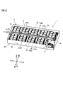
- FIG. 1 is an external perspective view of a power storage device according to a first embodiment.
- the perspective view which shows the internal structure of an electrical storage apparatus.
- the side view of an electrical storage module. (A) is the bottom view which looked at the electrical storage module from the lower part, (b) is the side surface cross-section schematic diagram of an electrical storage module.
- A) is a schematic sectional view taken along line VIIIa-VIIIa in FIG. 2, and
- (b) is a schematic sectional view taken along line VIIIb-VIIIb in FIG.
- (A) is a side view of the electrical storage module which concerns on 2nd Embodiment
- (b) is a side surface schematic diagram of the electrical storage module which concerns on 2nd Embodiment.
- the perspective view which shows typically the electrical storage apparatus which concerns on 3rd Embodiment.
- the perspective view which shows a module case and a cooling duct typically.
- FIG. 1 is an external perspective view of the power storage device according to the first embodiment
- FIG. 2 is a perspective view showing the internal structure of the power storage device
- FIG. 3 is a partial cross-sectional perspective view of the power storage device viewed from below.
- the left-right direction, the front-rear direction, and the up-down direction are as illustrated.
- the left-right direction, the front-rear direction, and the up-down direction are directions orthogonal to each other.
- the power storage device 1 is applied to an in-vehicle power supply device in an electric vehicle, for example, an electric motor drive system of an electric vehicle.
- the concept of the electric vehicle includes a hybrid electric vehicle provided with an engine which is an internal combustion engine and an electric motor as a driving source of the vehicle, a genuine electric vehicle using the electric motor as the only driving source of the vehicle, and the like.
- the power storage device 1 includes a device housing 30 including an upper lid 2 and a case main body 3 and a plurality of power storage modules 4 housed in the device housing 30.
- FIG. 2 shows the case body 3 with the upper lid 2 removed.
- the case body 3 has a rectangular parallelepiped shape with an upper opening.
- the case body 3 has a rectangular flat plate-shaped bottom plate 3e (see FIG. 3), a pair of long side plates 3a, 3b extending in the left-right direction, and a pair of short side plates 3c, 3d extending in the front-rear direction. .
- the power storage device 1 includes nine power storage modules 4 and an SD (service disconnect) switch 6.
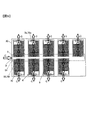
- the nine power storage modules 4 in the case body 3 are arranged in two rows, a front row and a back row.
- the five power storage modules 4 arranged in the front row are hereinafter referred to as front power storage modules 4f
- the four power storage modules 4 arranged in the rear row are hereinafter referred to as rear power storage modules 4r.
- Each front power storage module 4f is arranged in parallel with the long side plate 3a along the long side plate 3a.
- Each rear power storage module 4r is arranged along the long side plate 3b of the case body 3 in parallel with the long side plate 3b.
- An SD switch 6 is disposed at the left rear corner of the case body 3.
- the plurality of power storage modules 4 are electrically connected in series by a bus bar or the like.
- the SD switch 6 is provided between the plurality of power storage modules 4 constituting the battery block on the high potential side and the plurality of power storage modules 4 constituting the battery block on the low potential side.
- the SD switch 6 includes an electric circuit in which a switch (not shown) and a fuse are connected in series.
- the SD switch 6 is a safety device provided to ensure safety during maintenance and inspection of the power storage module 4.
- the SD switch 6 is operated by a service person when performing maintenance and inspection.
- the short side plate 3d is provided with a cooling air inlet 3i for introducing air (hereinafter referred to as cooling air C) as a cooling medium into the power storage device 1.
- the cooling air inlet 3i is an opening cut in a rectangular shape downward from the upper edge of the short side plate 3d.
- a blower pipe (not shown) that guides cooling air generated by a cooling fan (not shown) to the power storage device 1 is connected to the cooling air inlet 3i.
- the bottom plate 3e is provided with a plurality of cooling air outlet portions 3o for discharging the cooling air C from the power storage device 1.
- the plurality of cooling air outlet portions 3o are rectangular openings provided at equal intervals along the long side plates 3a and 3b in the vicinity of the long side plates 3a and 3b.
- the cooling air outlet 3o is provided corresponding to each power storage module 4.
- FIG. 4 is a perspective view of the power storage module 4, and FIG. 5 is a side view of the power storage module 4.
- FIG. FIG. 4B is a perspective view of the power storage module 4 viewed from the side opposite to FIG. 5A is a side view of the power storage module 4 of FIG. 4 viewed from the left side
- FIG. 5B is a side view of the power storage module 4 of FIG. 4 viewed from the right side. Since each power storage module 4 has the same configuration, one power storage module 4 arranged in the rear row shown in FIG. 2 will be described as a representative. Note that the front power storage module 4f and the rear power storage module 4r are disposed in opposite directions.
- the power storage module 4 has power storage elements 9 arranged in two upper and lower stages.
- Each power storage element 9 is, for example, a lithium ion battery and has a cylindrical shape.
- Each power storage element 9 is arranged so that the central axes of the power storage elements 9 are parallel to each other.
- Three storage elements 9 are arranged in the upper stage and four in the lower stage.
- the upper storage elements 9 are arranged so as to be shifted from the lower storage elements 9 by half the interval (pitch) of the storage elements 9 in the front-rear direction.
- each power storage element 9 in the upper stage is positioned at an intermediate position between the storage elements 9 arranged adjacent to each other in the lower stage in the axial center (axial center) of the power storage element 9. With this structure, the overall height of the power storage module 4 is reduced.
- Each storage element 9 is housed in a module case 70.
- the module case 70 is formed of an insulating member such as resin.
- the module case 70 is divided into two cases, a first divided case 70a and a second divided case 70b.
- Each of the first divided case 70a and the second divided case 70b has a length that is about half of the length of the electricity storage element 9 in the left-right direction.
- Each of the first divided case 70a and the second divided case 70b has three cylindrical spaces in the upper stage and four cylindrical spaces in the lower stage for accommodating the respective storage elements 9.
- a side edge 71a projecting sideways is formed at one end of the first split case 70a, and a side edge 71b projecting sideways is formed at the other end of the second split case 70b.
- a substantially cylindrical boss portion 72 is formed on the side edge 71b of the second divided case 70b, and an opening (not shown) corresponding to the boss portion 72 is formed on the side edge 71a of the first divided case 70a. ing.
- the storage element 9 is accommodated, and the bolt 31 is inserted into the boss portion 72 in a state where the side edge 71a and the side edge 71b are abutted with each other, and protrudes from the side edge 71a.
- the bolt 32 is fixed by fastening a nut 32 to the tip of the bolt 31 to be fixed.
- the storage elements 9 are electrically connected to each other by a bus bar 23 that is a conductive member.
- the positive electrode of the storage element 9 having the highest potential in each storage module 4 is connected to the positive terminal 11 of the storage module 4.
- the negative electrode of the storage element 9 having the lowest potential in each storage module 4 is connected to the negative terminal 12 of the storage module 4.
- the positive terminal 11 of each power storage module 4 is fixed to the upper surface of the right rear corner of the module case 70.
- the negative terminal 12 of each power storage module 4 is fixed to the upper surface of the left rear corner of the module case 70.
- the positive terminal 11 of one power storage module 4 and the negative terminal 12 of another power storage module 4 are connected by a conductive member (not shown).
- the upper storage elements 9 are arranged with a half-pitch shift relative to the lower storage elements 9, so that the upper storage elements 9 are connected to the lower ends. It is located on the inner side by a half pitch from the storage element 9. In other words, the dimension between both ends of the upper storage element 9 is shorter by one pitch than the dimension between both ends of the lower storage element 9.
- the module case 70 has three power storage elements 9 in the upper stage and four power storage elements 9 in the lower stage, and has a substantially trapezoidal column shape along the outer shape of the seven power storage elements 9. As shown in FIG. 4, the module case 70 includes a bottom plate 74, a top plate 75, an outer plate 76, an inner plate 77, and end plates 78 and 79.
- the bottom plate 74 is disposed below the power storage element 9, and the top plate 75 is disposed above the power storage element 9.
- the outer plate 76 and the inner plate 77 are disposed outward in the front-rear direction of the power storage element 9, and the end plates 78 and 79 are disposed outward in the left-right direction of the power storage element 9.
- a depression 76a is provided on the upper portion of the outer plate 76 that is one side plate in the front-rear direction.
- the inner side plate 77 which is the other side plate in the front-rear direction is provided with a cooling air introduction port 70 i which is an opening serving as an inlet for cooling air to the module case 70.
- FIG. 6A is a bottom view of the power storage module 4 as viewed from below, and FIG. 6B is a schematic side sectional view of the power storage module 4.
- the bottom plate 74 of the module case 70 is provided with a cooling air discharge port 70 o that is an opening for discharging cooling air from the module case 70.
- the cooling air discharge port 70o is provided in the vicinity of the outer plate 76 that is the side plate opposite to the side on which the cooling air introduction port 70i is provided.
- the inner plate 77 includes a vertical portion 77a that rises vertically from the bottom plate 74, an inclined portion 77b that extends obliquely upward from the upper end of the vertical portion 77a, and an inclined portion 77b. It has a connecting portion 77 c that connects the top plate 75.
- the vertical portion 77a is a portion that is disposed on the side of the lower storage element 9, and is forward of the portion that is disposed on the side of the upper storage element 9 (the inclined portion 77b and the connecting portion 77c). It is the protrusion part which protrudes toward.
- the outer plate 76 includes a lower vertical plate 76a that rises vertically from the bottom plate 74, a horizontal plate 76b that is bent 90 degrees from the upper end of the lower vertical plate 76a and extends inward, and an inner end portion of the horizontal plate 76b. And an upper vertical plate 76c bent upward by 90 degrees and extending upward. The upper end of the upper vertical plate 76 c is connected to the top plate 75.
- a plurality of legs 70L are provided at the lower end of the module case 70.
- the leg portion 70L is formed with a bolt insertion hole through which a bolt is inserted.
- the bolt is inserted into the bolt insertion hole of the leg portion 70 ⁇ / b> L, and the bolt is screwed into the screw hole formed in the bottom plate 3 e of the case body 3, whereby the power storage module 4 is fixed to the case body 3.
- the power storage device 1 has a right end portion that is one end portion in the longitudinal direction (left-right direction) of the device housing 30 and a second end portion in the longitudinal direction (left-right direction) of the device housing 30.
- a cooling duct 5 is provided so as to extend over a certain left end.
- the cooling duct 5 is disposed in a central portion of the device housing 30 in a short direction perpendicular to the longitudinal direction (left-right direction) of the power storage device 1, that is, in the front-rear direction. It is fixed by bonding or the like.
- a plurality of power storage modules 4 are arranged along the left-right direction on both sides in the front-rear direction across the cooling duct 5.
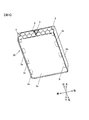
- FIG. 7 is a perspective view of the cooling duct 5.
- the cooling duct 5 supplies cooling air C from the outside of the module case 70 to the inside of the module case 70.
- the cooling duct 5 is a flow path forming body that forms a flow path through which the cooling air C passes, and is formed in a substantially trapezoidal cylindrical shape.
- the cooling duct 5 includes an upper surface plate 55, a pair of inclined plates 56 that extend obliquely downward from both front and rear ends of the upper surface plate 55, and a lower surface plate 57 that connects the pair of inclined plates 56.
- the pair of inclined plates 56 are inclined so that the distance between them becomes closer toward the bottom.
- the right end of the cooling duct 5 is a duct inlet 51 which is an opening for taking in cooling air generated by a cooling fan (not shown).
- the duct inlet 51 is disposed to face the cooling air inlet 3i of the case body 3 described above (see FIG. 2).
- the right end of the cooling duct 5 is a duct outlet 52 which is an opening for discharging cooling air from the cooling duct 5.
- the duct outlet 52 is connected to a guide duct that guides cooling air to other equipment (not shown). Note that the duct outlet 52 may be blocked by a not-shown closing plate or the like.
- Each of the pair of inclined plates 56 is provided with a plurality of cooling air outlets 50 at equal intervals along the longitudinal direction of the cooling duct 5.
- the cooling air outlet 50 is a rectangular opening that sends the cooling air C taken into the cooling duct 5 to each power storage module 4.
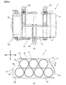
- FIG. 8A is a schematic sectional view taken along line VIIIa-VIIIa in FIG. 2, and FIG. 8B is a schematic sectional view taken along line VIIIb-VIIIb in FIG.
- Each front power storage module 4f and each rear power storage module 4r are arranged such that a vertical portion 77a protruding rearward in the front power storage module 4f and a vertical portion 77a protruding forward in the rear power storage module 4r face each other. ing.
- the protruding portions vertical portions 77a
- a substantially trapezoidal space SU is formed above the protruding portions, and a substantially rectangular shape is formed between the protruding portions.
- a space SL is formed.
- a space schematic diagram schematically showing the space SU and the space SL is shown in the lower right of FIG.
- the space SU is formed by a depression formed between the front power storage module 4f and the rear power storage module 4r, which is recessed downward from above.
- the space SU is defined by a pair of inclined portions 77b, a pair of connecting portions 77c, the upper lid 2, and the upper opening surface of the space SL, which are adjacent to each other in the front-rear direction.
- the space SL is defined by a pair of vertical portions 77a adjacent to each other in the front-rear direction, the bottom plate 3e, and a lower opening surface of the space SU.
- the cooling duct 5 is disposed in the space SU, and the cooling duct 5 and the power storage module are in a state where the inclined plate 56 of the cooling duct 5 and the inclined portion 77b of the module case 70 are in contact with each other. 4 are connected.
- the cooling duct 5 is disposed below (that is, inside) the upper end of the module case 70. For this reason, by providing the cooling duct 5, the height dimension of the apparatus housing 30 is not increased.
- the dimension in the height direction (vertical direction) of the cooling duct 5 is not more than half of the dimension in the height direction (vertical direction) of the apparatus housing 30. For this reason, the cooling duct 5 can be easily accommodated in the apparatus housing 30.
- the cooling duct 5 is arranged so that the opening edge of the cooling air outlet 50 of the cooling duct 5 and the opening edge of the cooling air inlet 70 i of the module case 70 substantially coincide with each other. ing.
- a sealing material (not shown) matching the shape of the opening is disposed between the opening edge of the cooling air outlet 50 and the opening edge of the cooling air inlet 70i, and the cooling duct 5 and the module case. The cooling air is prevented from leaking through the gap with 70.
- the cooling duct 5 is similarly connected to each of the nine power storage modules 4, and communicates with each of the nine power storage modules 4, so that nine power storage modules 4 are connected.
- the cooling air C is supplied to each of the modules 4.
- the power storage module 4 includes an opening edge of the cooling air outlet 70 o of the module case 70 and an opening of the cooling air outlet 3 o of the bottom plate 3 e of the case body 3 in the device housing 30. It arrange
- the space SL extends in the longitudinal direction of the power storage device 1 and detects the voltage of each power storage element 9, the voltage of each power storage module 4, and the current flowing through the power storage element 9. It can be used as a wiring region in which the wiring 60 connected to the detection element to be placed can be disposed.
- a space SC having a rectangular cross section is defined by the L-shaped depression 76 a provided in the upper part of the outer plate 76 of the module case 70 and the device housing 30.
- the space SC is formed between the upper vertical plate 76 c arranged to face the upper storage element 9 and the long side plate of the apparatus housing 30.
- the space SC like the space SL, extends in the longitudinal direction of the power storage device 1, and is connected to a detection element that detects the voltage of each power storage element 9, the voltage of each power storage module 4, and the current flowing through the power storage element 9.
- the wiring 60 can be used as a wiring region in which the wiring 60 can be disposed.
- FIG. 8B is a duct layout diagram schematically showing the positional relationship between the storage element 9 and the cooling duct 5 at the lower right of FIG. With reference to FIG.8 (b), arrangement
- the first element group 91 is configured by six power storage elements 9 arranged in the upper stage, which is the first stage, and is arranged in the lower stage, which is the second stage.
- a second element group 92 is configured by the eight power storage elements 9.
- the cooling duct 5 is disposed between the pair of adjacent power storage elements 9C and 9D.
- the cooling duct 5 extends from a direction orthogonal to the arrangement direction (front-rear direction) of the plurality of power storage elements 9 constituting the first element group 91, that is, from the vertical direction of the power storage device 1.
- the cooling duct 5 is disposed so as to overlap the predetermined power storage elements 9J and 9K constituting the second element group 92.
- a virtual plane V orthogonal to the vertical direction, a projection unit 5p of the cooling duct 5 projected onto the virtual plane V, and a projection unit of the storage element 9J 9p is a schematic projection view schematically showing 9pj and the projection unit 9pk of the electricity storage element 9K.
- 8A when the cooling duct 5 and the power storage elements 9J and 9K are projected from above the power storage device 1, the projection 5p of the cooling duct 5 and the projection 9pj of the power storage element 9J are obtained.
- Overlap area 59j is formed by overlapping, and projection area 5p of cooling duct 5 and projection area 9pk of power storage element 9K overlap to form overlap area 59k.
- the space in the device housing 30 can be effectively used. That is, it is possible to prevent the apparatus housing 30 from becoming large due to the installation of the cooling duct 5.
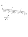
- FIG. 9 is a schematic diagram for explaining the cooling air C flowing in the power storage device 1.
- the cooling air C introduced from the cooling air inlet 3 i of the device housing 30 into the device housing 30 is supplied into the cooling duct 5 from the duct inlet 51.
- the cooling air C supplied into the cooling duct 5 is discharged from each cooling air outlet 50 while flowing along the longitudinal direction of the cooling duct 5.
- the cooling air C discharged from the cooling air outlet 50 is supplied into the module case 70 from the cooling air inlet 70 i of the module case 70.
- the cooling air C supplied to the inside of the module case 70 flows along the outer surface of the electricity storage element 9, absorbs the heat of the electricity storage element 9, and passes from the cooling air outlet 70 o of the module case 70 to the outside of the module case 70. Discharged.
- the cooling air C discharged from the cooling air outlet 70o of the module case 70 is discharged from the cooling air outlet 3o of the device housing 30 to the outside of the device housing 30.
- the power storage device 1 includes one or more power storage modules 4 each having a plurality of power storage elements 9 and a module case 70 that houses the plurality of power storage elements 9.
- the power storage device 1 includes a first element group 91 in which a plurality of power storage elements 9 are arranged in a first stage, a second element group 92 in which a plurality of power storage elements 9 are arranged in a second stage, and a module case 70.
- the cooling duct 5 for supplying cooling air to the inside of the module case 70 from the outside is provided.
- the cooling duct 5 is arranged between a pair of adjacent power storage elements 9C and 9D in the first element group 91. For this reason, the cooling duct 5 can be provided in the power storage device 1 without increasing the height dimension (vertical size) of the power storage device 1.
- the cooling duct 5 when the cooling duct 5 is viewed from a direction (vertical direction) orthogonal to the arrangement direction of the plurality of power storage elements 9 constituting the first element group 91, the cooling duct 5 is a predetermined element constituting the second element group 92. Are arranged so as to overlap the power storage elements 9J and 9K. For this reason, the increase in the width dimension (front-rear direction dimension) of the power storage device 1 due to the provision of the cooling duct 5 can be suppressed.
- the power storage device 1 can be downsized while ensuring the cooling performance of the power storage device 1.
- the power storage device 1 includes a device housing 30 that houses a plurality of power storage modules 4.
- the cooling duct 5 is connected to each of the plurality of power storage modules 4, communicates with each of the plurality of power storage modules 4, and supplies a cooling medium to each of the plurality of power storage modules 4.
- the cooling duct 5 is disposed at the center portion in the front-rear direction of the device housing 30 so as to extend from the left end portion of the device housing 30 to the right end portion.
- a plurality of power storage modules 4 are arranged along the left-right direction of the device housing 30 on both sides in the front-rear direction across the cooling duct 5.
- the plurality of front power storage modules 4 f arranged on the front side of the cooling duct 5 are formed so that a part of the end on the connection side with the cooling duct 5 protrudes to the rear side of the cooling duct 5.
- the plurality of rear power storage modules 4r arranged on the rear side of the cooling duct 5 are formed such that a part of the end portion on the connection side with the cooling duct 5 protrudes to the front side of the cooling duct 5.
- a vertical portion 77a which is a protruding portion of the plurality of front power storage modules 4f disposed on the front side of the cooling duct 5, and a vertical portion 77a which is a protruding portion of the plurality of rear power storage modules 4r disposed on the rear side of the cooling duct 5.
- a plurality of front power storage modules 4f and a plurality of rear power storage modules 4r are arranged.
- the cooling duct 5 is disposed in a recess formed between the plurality of front power storage modules 4f and the plurality of rear power storage modules 4r.
- the cooling air is efficiently supplied to a large number of power storage modules 4 with one cooling duct 5. be able to. Since there is no need to provide a plurality of cooling ducts 5, it is possible to prevent the apparatus housing 30 from becoming large.
- a space SL as a wiring region in which the wiring 60 is disposed is formed between the vertical portion 77a that is the protruding portion of the front power storage module 4f and the vertical portion 77a that is the protruding portion of the rear power storage module 4r. ing. For this reason, the space below the cooling duct 5 can be effectively utilized. In other words, it is possible to prevent the apparatus housing 30 from becoming large by providing a space for routing the wiring 60 separately.
- the dimension in the height direction of the cooling duct 5 is set to be not more than half of the dimension in the height direction of the apparatus housing 30. For this reason, even if the height dimension of the device casing 30 is set to the same height as that when the cooling duct 5 is not provided, the cooling duct 5 can be easily accommodated in the device casing 30. .
- the plurality of power storage elements 9 are arranged such that the central axes of the cylindrical power storage elements 9 are parallel to each other.
- the number of power storage elements 9 constituting the first element group 91 (six in the above example) is smaller than the number of power storage elements 9 constituting the second element group 92 (eight in the above example).
- the plurality of power storage elements 9 constituting the element group 91 are located at positions shifted by a half pitch with respect to the power storage elements 9 constituting the second element group 92 and are adjacent to each other in the second element group 92. Arranged between the storage elements 9.
- the long side plates 3a and 3b of the device housing 30 and the long side plates 3a and 3b of the device housing 30 A space SC as a wiring region in which the wiring 60 is disposed is provided between the power storage elements 9 constituting the first element group 91 disposed to face each other. For this reason, the space of the side of the 1st element group 91 can be used effectively. In other words, it is possible to prevent the apparatus housing 30 from becoming large by providing a space for routing the wiring 60 separately.
- FIG. 10A is a view similar to FIG. 5A and is a side view showing the power storage module 204 according to the second embodiment.
- FIG. 10B is a schematic side sectional view of the power storage module 204 according to the second embodiment.
- the cooling duct 5 is disposed in the recess (space SU) formed between the front power storage module 4f and the rear power storage module 4r.
- the power storage module 204 is an integrated unit in which the front power storage module 4f and the rear power storage module 4r described in the first embodiment are coupled by the vertical portion 77a of the module case 70. Structure.
- the cooling duct 5 is disposed in a recess 273 provided in the center in the front-rear direction of the power storage module 204.
- the following functions and effects are obtained. Play. (6)
- the space SL (see FIG. 8A) described in the first embodiment is not formed, but the dimension in the front-rear direction can be shortened by the amount that the space SL is not formed. (7) Compared with the first embodiment, the number of parts can be reduced.
- FIG. 11 is a perspective view schematically showing a power storage device 301 according to the third embodiment.
- the device housing 3030 is indicated by a two-dot chain line.
- one storage module 304 is in the area surrounded by a broken line.
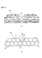
- FIG. 12 is a perspective view schematically showing the module case 370 and the cooling duct 305.
- the power storage device 1 according to the first embodiment includes a plurality of power storage modules 4 each including a cylindrical power storage element 9.
- the power storage device 301 according to the third embodiment includes a plurality of power storage modules 304 each including an angular storage element 309.
- each power storage module 304 includes nine power storage elements 309. Four power storage elements 309 are arranged in the upper stage and five in the lower stage.
- the upper storage element 9 and the lower storage element 9 are arranged with a half-pitch offset, but in the third embodiment, the upper storage element 309 and the lower storage element 9
- the power storage elements 309 are arranged without shifting.
- the upper power storage element 309 is not disposed above the innermost power storage element 309 in the lower power storage element 309.
- An L-shaped depression 376a is provided.
- a cooling air inlet 370 i that is an opening is formed in the inner plate 377 that covers the side of the upper storage element 309.
- a cooling air discharge port 370 o that is an opening is formed in the outer plate 376 that covers the side of the lower storage element 309.
- the cooling duct 305 has a rectangular cylindrical shape including a pair of side plates 356, an upper surface plate, and a lower surface plate.
- a plurality of cooling air outlets 350 are provided at equal intervals along the longitudinal direction of the cooling duct 305 in each of the pair of side plates 356 of the cooling duct 305.
- the end plate 358 at one end of the cooling duct 305 is provided with a duct inlet 351 that is an inlet opening for cooling air.
- the cooling air supplied from the duct inlet 351 into the cooling duct 305 flows along the longitudinal direction of the cooling duct 305, and from each cooling air outlet 350 through the cooling air inlet 370i, It is introduced into the module case 370.
- the cooling air introduced into the electricity storage module 304 absorbs heat generated in each electricity storage element 9 and is discharged from the cooling air outlet 370o to the outside of the module case 370.
- the shapes of the device housing 30, the module case 70, and the cooling duct 5 are not limited to the above-described embodiments.
- the protruding portion of the module case 70 may be a curved portion instead of the vertical portion 77a.
- the shape of the cooling ducts 5 and 5C is not limited to the case of a hollow trapezoidal column shape (see FIG. 7) or a rectangular tube shape (see FIG. 12), but other polygonal cylinder shapes, cylindrical shapes, and elliptic cylinder shapes. It can be made into various shapes.
- a plurality of power storage elements may be arranged in three or more stages.
- the cooling duct can be arranged in a space formed by removing a part of the power storage elements arranged at predetermined intervals in the upper stage.
- a cooling duct can be arranged in a space formed by removing a part of the upper and middle power storage elements.
- a cooling duct can be arranged in a space formed by removing a part of the middle stage power storage element.
- Modification 4 Although the lithium ion battery has been described as an example of the electricity storage elements 9 and 309, the present invention can be applied to other secondary batteries such as a nickel metal hydride battery. Furthermore, the present invention can be applied to a power storage module using an electric double layer capacitor or a lithium ion capacitor as a power storage element.
Landscapes
- Engineering & Computer Science (AREA)
- Power Engineering (AREA)
- Manufacturing & Machinery (AREA)
- Chemical & Material Sciences (AREA)
- Chemical Kinetics & Catalysis (AREA)
- Electrochemistry (AREA)
- General Chemical & Material Sciences (AREA)
- Microelectronics & Electronic Packaging (AREA)
- Physics & Mathematics (AREA)
- Algebra (AREA)
- General Physics & Mathematics (AREA)
- Mathematical Analysis (AREA)
- Mathematical Optimization (AREA)
- Pure & Applied Mathematics (AREA)
- Secondary Cells (AREA)
- Battery Mounting, Suspending (AREA)
- Electric Double-Layer Capacitors Or The Like (AREA)
Abstract
蓄電装置の冷却性能を確保しつつ、蓄電装置の小型化を図る。蓄電装置は、複数の蓄電素子および複数の蓄電素子を収容するケースを有する1以上の蓄電モジュールを備えた蓄電装置であって、複数の蓄電素子がN段目(Nは1以上の整数)に配列されてなる第1素子群と、複数の蓄電素子が(N+1)段目に配列されてなる第2素子群と、ケースの外部からケースの内部に冷却媒体を供給するダクトと、を備え、ダクトは、第1素子群において隣接する一対の蓄電素子間であって、かつ、第1素子群を構成する複数の蓄電素子の配列方向と直交する方向から見たときに、ダクトが第2素子群を構成する所定の蓄電素子に重なるように配置されている。
Description
本発明は、蓄電装置に関する。
ハイブリッド電気自動車や純粋な電気自動車に搭載される蓄電装置は、たとえば、リチウムイオン電池、ニッケル水素電池等の多数の蓄電素子を備えている。蓄電素子は、充放電の際、内部抵抗に起因した発熱が生じ、温度が上昇するほど、容量減少等の寿命に関する性能劣化が起こりやすくなる。蓄電素子の温度上昇は、寿命の観点からできるだけ小さくすることが望ましい。従来、蓄電素子を冷却する構造を備えた蓄電装置が種々提案されている。
特許文献1には、電池モジュールに冷却風を導入するクーリングダクトを備えた車両用バッテリ装置が記載されている。特許文献1に記載のクーリングダクトは、電池モジュール間バスバーの上方を覆うと共に冷却風が主に送風されるダクト主流部と、2つの列の電池モジュールの間に設けられ、下端が電池モジュールの下部近辺まで突出した断面U字状のモジュール間配設部とを併せ持った形状とされている。
蓄電装置は、様々な機械に搭載されるが、特に車両に搭載される蓄電装置では、車両への搭載空間が限られていることから、冷却性能だけでなく、小型化が強く要望されている。上記特許文献1に記載の電池モジュールでは、小型化の観点から改善の余地がある。
蓄電装置は、複数の蓄電素子および複数の蓄電素子を収容するケースを有する1以上の蓄電モジュールを備えた蓄電装置であって、複数の蓄電素子がN段目(Nは1以上の整数)に配列されてなる第1素子群と、複数の蓄電素子が(N+1)段目に配列されてなる第2素子群と、ケースの外部からケースの内部に冷却媒体を供給するダクトと、を備え、ダクトは、第1素子群において隣接する一対の蓄電素子間であって、かつ、第1素子群を構成する複数の蓄電素子の配列方向と直交する方向から見たときに、ダクトが第2素子群を構成する所定の蓄電素子に重なるように配置されている。
本発明によれば、蓄電装置の冷却性能を確保しつつ、蓄電装置の小型化を図ることができる。
-第1の実施形態-
以下、図面を参照して、本発明の蓄電装置の第1の実施形態を説明する。
図1は第1の実施形態に係る蓄電装置の外観斜視図であり、図2は蓄電装置の内部構造を示す斜視図である。図3は、下方から見た蓄電装置の一部断面斜視図である。なお、説明の便宜上、本明細書において、左右方向、前後方向および上下方向は、図示の通りとする。左右方向、前後方向および上下方向は、互いに直交する方向である。
以下、図面を参照して、本発明の蓄電装置の第1の実施形態を説明する。
図1は第1の実施形態に係る蓄電装置の外観斜視図であり、図2は蓄電装置の内部構造を示す斜視図である。図3は、下方から見た蓄電装置の一部断面斜視図である。なお、説明の便宜上、本明細書において、左右方向、前後方向および上下方向は、図示の通りとする。左右方向、前後方向および上下方向は、互いに直交する方向である。
蓄電装置1は、電動車両、たとえば電気自動車の電動機駆動システムにおける車載電源装置に適用される。この電気自動車の概念には、内燃機関であるエンジンと電動機とを車両の駆動源として備えたハイブリッド電気自動車、および電動機を車両の唯一の駆動源とする純正電気自動車等が含まれる。
蓄電装置1は、上蓋2およびケース本体3からなる装置筐体30と、装置筐体30内に収納される複数の蓄電モジュール4とを備えている。図2は、上蓋2を取り外した状態のケース本体3を示している。ケース本体3は、上方が開口された直方体形状とされている。ケース本体3は、矩形平板状の底板3e(図3参照)と、左右方向に延在する一対の長辺側板3a,3bおよび前後方向に延在する一対の短辺側板3c,3dとを有する。
蓄電装置1は、9個の蓄電モジュール4と、SD(サービスディスコネクト)スイッチ6とを備えている。ケース本体3内の9個の蓄電モジュール4は、前列と後列の二列に配列されている。前列に配列される5個の蓄電モジュール4を以下では、前側蓄電モジュール4fと称し、後列に配列される4個の蓄電モジュール4を以下では、後側蓄電モジュール4rと称する。各前側蓄電モジュール4fは、長辺側板3aに沿って、長辺側板3aと平行に配列されている。各後側蓄電モジュール4rは、ケース本体3の長辺側板3bに沿って、長辺側板3bと平行に配列されている。ケース本体3の左後隅部には、SDスイッチ6が配置されている。
複数の蓄電モジュール4は、バスバー等により、電気的に直列に接続されている。SDスイッチ6は、高電位側の電池ブロックを構成する複数の蓄電モジュール4と、低電位側の電池ブロックを構成する複数の蓄電モジュール4との間に設けられている。SDスイッチ6は、図示しないスイッチとヒューズとを直列に接続した電気回路から構成され、蓄電モジュール4の保守、点検の際の安全性を確保するために設けられた安全装置である。SDスイッチ6は、サービスマンによって、保守、点検を行う際に操作される。
図2に示すように、短辺側板3dには、冷却媒体である空気(以下、冷却風Cと記す)を蓄電装置1に導入する冷却風入口部3iが設けられている。冷却風入口部3iは、短辺側板3dの上端縁から下方に向かって矩形状に切りかかれた開口である。冷却風入口部3iには、図示しない冷却ファンで発生した冷却風を蓄電装置1に案内する送風管(不図示)が接続される。
図3に示すように、底板3eには、冷却風Cを蓄電装置1から排出する複数の冷却風出口部3oが設けられている。複数の冷却風出口部3oは、長辺側板3a,3bの近傍において、長辺側板3a,3bに沿って等間隔に設けられた矩形状の開口である。冷却風出口部3oは、各蓄電モジュール4に対応して設けられている。
図4は蓄電モジュール4の斜視図であり、図5は蓄電モジュール4の側面図である。図4(b)は、図4(a)とは反対側から見た蓄電モジュール4の斜視図である。図5(a)は図4の蓄電モジュール4を左側から見た側面図であり、図5(b)は図4の蓄電モジュール4を右側から見た側面図である。各蓄電モジュール4は、同様の構成を有しているため、図2に示す後列に配置される一の蓄電モジュール4を代表して説明する。なお、前側蓄電モジュール4fと後側蓄電モジュール4rとは、左右逆向きに配置されている。
蓄電モジュール4は、上下2段に配列された蓄電素子9を有する。各蓄電素子9は、たとえば、リチウムイオン電池であり、円筒状とされている。各蓄電素子9は、蓄電素子9の中心軸が互いに平行となるように配置されている。蓄電素子9は上段に3個配列され、下段に4個配列されている。上段の各蓄電素子9は、前後方向において、下段の各蓄電素子9とは、各蓄電素子9の間隔(ピッチ)の半分ずつずれて配列されている。換言すれば、上段の各蓄電素子9は、蓄電素子9の軸方向の中心(軸心)が下段において隣接して配置される蓄電素子9の間隔の中間位置に位置している。この構造により、蓄電モジュール4の全高の寸法を小さくしている。
各蓄電素子9は、モジュールケース70内に収容されている。モジュールケース70は、樹脂などの絶縁性部材により形成される。モジュールケース70は、第1分割ケース70aと第2分割ケース70bの2つのケースに分割されている。第1分割ケース70aおよび第2分割ケース70bは、それぞれ蓄電素子9の左右方向の長さの半分程度の長さを有する。第1分割ケース70aおよび第2分割ケース70bは、それぞれ、各蓄電素子9を収容するための、上段に3個、下段に4個の円筒形空間を有している。
図4に示すように、第1分割ケース70aの一端には、側方に突出する側縁71aが形成され、第2分割ケース70bの他端には、側方に突出する側縁71bが形成されている。第2分割ケース70bの側縁71bには、略円筒状のボス部72が形成され、第1分割ケース70aの側縁71aには、ボス部72に対応する開口(図示せず)が形成されている。第1分割ケース70aおよび第2分割ケース70bは、蓄電素子9が収容され、側縁71aと側縁71bとを突き合わせられた状態で、ボス部72にボルト31が挿通され、側縁71aから突出するボルト31の先端にナット32を締結することにより、固定される。
蓄電素子9同士は、導電部材であるバスバー23により、相互に電気的に接続される。
各蓄電モジュール4における最高電位の蓄電素子9の正極は、蓄電モジュール4の正極端子11に接続される。各蓄電モジュール4における最低電位の蓄電素子9の負極は、蓄電モジュール4の負極端子12に接続される。各蓄電モジュール4の正極端子11は、モジュールケース70の右後方の隅部の上面に固定される。各蓄電モジュール4の負極端子12は、モジュールケース70の左後方の隅部の上面に固定される。図2に示す隣り合う蓄電モジュール4のうち、一の蓄電モジュール4の正極端子11と、他の蓄電モジュール4の負極端子12とは、図示しない導電部材によりに接続される。
各蓄電モジュール4における最高電位の蓄電素子9の正極は、蓄電モジュール4の正極端子11に接続される。各蓄電モジュール4における最低電位の蓄電素子9の負極は、蓄電モジュール4の負極端子12に接続される。各蓄電モジュール4の正極端子11は、モジュールケース70の右後方の隅部の上面に固定される。各蓄電モジュール4の負極端子12は、モジュールケース70の左後方の隅部の上面に固定される。図2に示す隣り合う蓄電モジュール4のうち、一の蓄電モジュール4の正極端子11と、他の蓄電モジュール4の負極端子12とは、図示しない導電部材によりに接続される。
図4および図5に示すように、上段の各蓄電素子9が下段の各蓄電素子9に対し、半ピッチずつずれて配列されているため、上段の両端の蓄電素子9は、下段の両端の蓄電素子9よりも半ピッチだけ内側に位置している。換言すれば、下段の蓄電素子9の両端部間の寸法に比べて、上段の蓄電素子9の両端部間の寸法は、1ピッチ分短い。
モジュールケース70は、上段に3個の蓄電素子9、下段に4個の蓄電素子9を収容し、7個の蓄電素子9の外形に沿う略台形柱状とされている。図4に示すように、モジュールケース70は、底板74と、天板75と、外側板76と、内側板77と、端板78,79とで概略構成される。
底板74は蓄電素子9の下方に配置され、天板75は蓄電素子9の上方に配置される。
外側板76および内側板77は蓄電素子9の前後方向外方に配置され、端板78,79は蓄電素子9の左右方向外方に配置される。前後方向の一方の側板である外側板76の上部には、窪み76aが設けられている。前後方向の他方の側板である内側板77には、モジュールケース70への冷却風の入口となる開口である冷却風導入口70iが設けられている。
外側板76および内側板77は蓄電素子9の前後方向外方に配置され、端板78,79は蓄電素子9の左右方向外方に配置される。前後方向の一方の側板である外側板76の上部には、窪み76aが設けられている。前後方向の他方の側板である内側板77には、モジュールケース70への冷却風の入口となる開口である冷却風導入口70iが設けられている。
図6(a)は蓄電モジュール4を下方から見た底面図であり、図6(b)は蓄電モジュール4の側面断面模式図である。図6に示すように、モジュールケース70の底板74には、モジュールケース70から冷却風を排出する開口である冷却風排出口70oが設けられている。図6(b)に示すように、冷却風排出口70oは、冷却風導入口70iが設けられる側とは反対側の側板である外側板76の近傍に設けられている。
図6(b)に模式的に示すように、内側板77は、底板74から垂直に立ち上がる垂直部77aと、垂直部77aの上端から斜め上方に延在する傾斜部77bと、傾斜部77bと天板75とを繋ぐ連結部77cとを有している。垂直部77aは、下段の蓄電素子9の側方に配置される部分であって、上段の蓄電素子9の側方に配置される部分(傾斜部77bや連結部77c)に比べて、前方に向かって突出する突出部位である。
外側板76は、底板74から垂直に立ち上がる下側縦板76aと、下側縦板76aの上端から90度屈曲し、内側に向かって延在する横板76bと、横板76bの内側端部から90度屈曲し、上方に向かって延在する上側縦板76cとを有している。上側縦板76cの上端は天板75に接続されている。
図4~図6に示すように、モジュールケース70の下端部には、複数の脚部70Lが設けられている。脚部70Lには、ボルトが挿通されるボルト挿通孔が形成されている。脚部70Lのボルト挿通孔にボルトが挿通され、ケース本体3の底板3eに形成されたネジ孔にボルトが螺合されることで蓄電モジュール4がケース本体3に固定される。
本実施の形態に係る蓄電装置1の冷却構造について説明する。図2に示すように、蓄電装置1は、装置筐体30の長手方向(左右方向)の一方側端部である右端部から装置筐体30の長手方向(左右方向)の他方側端部である左端部に亘って延びるように配置される冷却ダクト5を備えている。冷却ダクト5は、蓄電装置1の長手方向(左右方向)に直交する短手方向、すなわち前後方向の装置筐体30における中央部に配置され、蓄電モジュール4および/またはケース本体3にねじ止めや接着等により固定されている。冷却ダクト5を挟んだ前後方向の両側には、それぞれ、蓄電モジュール4が複数、左右方向に沿って配置されている。
図7は、冷却ダクト5の斜視図である。冷却ダクト5は、モジュールケース70の外部からモジュールケース70の内部に冷却風Cを供給する。冷却ダクト5は、内部に冷却風Cを通す流路を形成する流路形成体であって、略台形筒状に形成されている。冷却ダクト5は、上面板55と、上面板55の前後両端のそれぞれから斜め下方に延在する一対の傾斜板56と、一対の傾斜板56同士を連結する下面板57とを備えている。一対の傾斜板56は、下方に向かうほど互いの距離が近くなるように傾斜している。
冷却ダクト5の右端は、図示しない冷却ファンで発生した冷却風を取り入れる開口であるダクト入口部51とされる。ダクト入口部51は、上述したケース本体3の冷却風入口部3iに対向して配置される(図2参照)。冷却ダクト5の右端は、冷却風を冷却ダクト5から排出する開口であるダクト出口部52とされる。ダクト出口部52は、図示しない他の機器に冷却風を案内する案内ダクトに連結される。なお、ダクト出口部52は、図示しない閉止板等により塞いでもよい。
一対の傾斜板56のそれぞれには、複数の冷却風送出口50が冷却ダクト5の長手方向に沿って等間隔に設けられている。冷却風送出口50は、冷却ダクト5に取り入れられた冷却風Cを各蓄電モジュール4に送出する矩形状の開口である。
図8(a)は図2のVIIIa-VIIIa線断面模式図であり、図8(b)は図2のVIIIb-VIIIb線断面模式図である。各前側蓄電モジュール4fと各後側蓄電モジュール4rとは、前側蓄電モジュール4fにおいて後方に突出する垂直部77aと、後側蓄電モジュール4rにおいて前方に突出する垂直部77aとが対向するように配置されている。前後方向に隣接する蓄電モジュール4の下部における突出部位(垂直部77a)同士を対向配置させることで、突出部位の上部に略台形状の空間SUが形成され、突出部位間には略矩形状の空間SLが形成される。
図8(a)の右下に、空間SUおよび空間SLを模式的に示す空間模式図を示す。この空間模式図に示されるように、空間SUは、前側蓄電モジュール4fと後側蓄電モジュール4rとの間に形成された、上方から下方に向かって凹んだ窪みにより形成される。空間SUは、前後方向に隣接する蓄電モジュール4の一対の傾斜部77bと、一対の連結部77cと、上蓋2と、空間SLの上部開口面とによって画成される。空間SLは、前後方向に隣接する一対の垂直部77aと、底板3eと、空間SUの下部開口面とによって画成される。
図8(b)に示すように、冷却ダクト5は空間SUに配置され、冷却ダクト5の傾斜板56とモジュールケース70の傾斜部77bとが当接された状態で、冷却ダクト5と蓄電モジュール4とが連結されている。冷却ダクト5は、モジュールケース70の上端よりも下側(つまり、内側)に配置されている。このため、冷却ダクト5を設けることで、装置筐体30の高さ寸法が大きくなってしまうことはない。なお、冷却ダクト5における高さ方向(上下方向)の寸法は、装置筐体30における高さ方向(上下方向)の寸法の半分以下とされている。このため、冷却ダクト5を装置筐体30内に容易に納めることができる。
図8(b)に示すように、冷却ダクト5は、冷却ダクト5の冷却風送出口50の開口縁と、モジュールケース70の冷却風導入口70iの開口縁とが略一致するように配置されている。なお、冷却風送出口50の開口縁と、冷却風導入口70iの開口縁との間には、開口の形状に合わせたシール材(不図示)が配置されており、冷却ダクト5とモジュールケース70との隙間から冷却風が漏れ出ることが防止されている。
なお、図2および図8に示すように、冷却ダクト5は、9個の蓄電モジュール4のそれぞれに対して同様に連結されて、9個の蓄電モジュール4のそれぞれと連通し、9個の蓄電モジュール4のそれぞれに対して冷却風Cを供給する構成とされている。
図8(b)に示すように、蓄電モジュール4は、装置筐体30内において、モジュールケース70の冷却風排出口70oの開口縁と、ケース本体3の底板3eの冷却風出口部3oの開口縁とが略一致するように配置されている。
図8(a)に示すように、空間SLは、蓄電装置1の長手方向に延在しており、各蓄電素子9の電圧や、各蓄電モジュール4の電圧、蓄電素子9に流れる電流を検出する検出素子に接続される配線60を配置させることができる配線領域として使用することができる。
モジュールケース70の外側板76の上部に設けられた側面視L字状の窪み76aと装置筐体30とにより、断面矩形状の空間SCが画成されている。この空間SCは、上段の蓄電素子9に対向して配置される上側縦板76cと、装置筐体30の長辺側板との間に形成される。空間SCは、空間SLと同様、蓄電装置1の長手方向に延在しており、各蓄電素子9の電圧や、各蓄電モジュール4の電圧、蓄電素子9に流れる電流を検出する検出素子に接続される配線60を配置させることができる配線領域として使用することができる。
図8(b)の右下に、蓄電素子9と冷却ダクト5の位置関係を模式的に示すダクト配置図を示す。図8(b)を参照して、蓄電素子9に対する冷却ダクト5の配置について詳しく説明する。図8(b)のダクト配置図に示すように、1段目である上段に配列される6個の蓄電素子9により第1素子群91が構成され、2段目である下段に配列される8個の蓄電素子9により第2素子群92が構成される。
第1素子群91を構成する6個の蓄電素子9のうち、装置筐体30の前端から3個目の蓄電素子9Cと、モジュールケース70の前端から4個目の蓄電素子9Dとの間には、空間SU(図8(a)参照)が設けられている。冷却ダクト5は、この隣接する一対の蓄電素子9C,9D間に配置されている。
さらに、図8(a)に示すように、冷却ダクト5は、第1素子群91を構成する複数の蓄電素子9の配列方向(前後方向)と直交する方向、すなわち蓄電装置1の上下方向から見たときに、冷却ダクト5が第2素子群92を構成する所定の蓄電素子9J,9Kに重なるように配置されている。
図8(a)では、蓄電装置1の断面模式図の下に、上下方向に直交する仮想平面Vと、仮想平面Vに投影された冷却ダクト5の投影部5pと、蓄電素子9Jの投影部9pjと、蓄電素子9Kの投影部9pkとを模式的に示す投影模式図を示している。図8(a)の投影模式図に示すように、蓄電装置1の上方から冷却ダクト5および蓄電素子9J,9Kを投影すると、冷却ダクト5の投影部5pと蓄電素子9Jの投影部9pjとが重なって重なり領域59jが形成され、冷却ダクト5の投影部5pと蓄電素子9Kの投影部9pkとが重なって重なり領域59kが形成される。このように、蓄電素子9と冷却ダクト5の実装領域を重複させることで、装置筐体30内のスペースを有効利用できる。つまり、冷却ダクト5を設置することに起因して、装置筐体30が大きくなることを抑制できる。
図2、図3、図7、図8(b)および図9を参照して、蓄電装置1内に導入される冷却風Cの流れについて説明する。図9は、蓄電装置1内を流れる冷却風Cについて説明する模式図である。図2および図9に示すように、装置筐体30の冷却風入口部3iから装置筐体30の内部に導入された冷却風Cは、ダクト入口部51から冷却ダクト5内に供給される。図7および図9に示すように、冷却ダクト5内に供給された冷却風Cは、冷却ダクト5の長手方向に沿って流れつつ、各冷却風送出口50から排出される。
図8(b)および図9に示すように、冷却風送出口50から排出された冷却風Cは、モジュールケース70の冷却風導入口70iからモジュールケース70内に供給される。モジュールケース70の内部に供給された冷却風Cは、蓄電素子9の外表面に沿って流れ、蓄電素子9の熱を吸収し、モジュールケース70の冷却風排出口70oからモジュールケース70の外部に排出される。
モジュールケース70の冷却風排出口70oから排出された冷却風Cは、装置筐体30の冷却風出口部3oから装置筐体30の外部に排出される。
上述した実施の形態によれば、次の作用効果が得られる。
(1)蓄電装置1は、複数の蓄電素子9および複数の蓄電素子9を収容するモジュールケース70を有する1以上の蓄電モジュール4を備えている。蓄電装置1は、複数の蓄電素子9が1段目に配列されてなる第1素子群91と、複数の蓄電素子9が2段目に配列されてなる第2素子群92と、モジュールケース70の外部からモジュールケース70の内部に冷却風を供給する冷却ダクト5を備えている。冷却ダクト5は、第1素子群91において隣接する一対の蓄電素子9C,9D間に配置されている。このため、蓄電装置1の高さ寸法(上下方向寸法)を増加させることなく、冷却ダクト5を蓄電装置1に設けることができる。
(1)蓄電装置1は、複数の蓄電素子9および複数の蓄電素子9を収容するモジュールケース70を有する1以上の蓄電モジュール4を備えている。蓄電装置1は、複数の蓄電素子9が1段目に配列されてなる第1素子群91と、複数の蓄電素子9が2段目に配列されてなる第2素子群92と、モジュールケース70の外部からモジュールケース70の内部に冷却風を供給する冷却ダクト5を備えている。冷却ダクト5は、第1素子群91において隣接する一対の蓄電素子9C,9D間に配置されている。このため、蓄電装置1の高さ寸法(上下方向寸法)を増加させることなく、冷却ダクト5を蓄電装置1に設けることができる。
さらに、冷却ダクト5は、第1素子群91を構成する複数の蓄電素子9の配列方向と直交する方向(上下方向)から見たときに、冷却ダクト5が第2素子群92を構成する所定の蓄電素子9J,9Kに重なるように配置されている。このため、冷却ダクト5を設けることに起因する蓄電装置1の幅寸法(前後方向寸法)の増加を抑えることができる。
つまり、本実施の形態によれば、蓄電装置1の冷却性能を確保しつつ蓄電装置1の小型化を図ることができる。
(2)本実施形態に係る蓄電装置1は、複数の蓄電モジュール4を収納する装置筐体30を備えている。冷却ダクト5は、複数の蓄電モジュール4のそれぞれに連結されて、複数の蓄電モジュール4のそれぞれと連通し、複数の蓄電モジュール4のそれぞれに対して冷却媒体を供給する構成とされている。冷却ダクト5は、装置筐体30の左端部から右端部に延びるように、装置筐体30の前後方向の中央部に配置されている。冷却ダクト5を挟んだ前後方向両側には、それぞれ、蓄電モジュール4が複数、装置筐体30の左右方向に沿って配置されている。
冷却ダクト5の前方側に配置された複数の前側蓄電モジュール4fは、冷却ダクト5との連結側の端部の一部が冷却ダクト5の後方側に突出するように形成されている。同様に、冷却ダクト5の後方側に配置された複数の後側蓄電モジュール4rは、冷却ダクト5との連結側の端部の一部が冷却ダクト5の前方側に突出するように形成されている。冷却ダクト5の前側に配置された複数の前側蓄電モジュール4fの突出部位である垂直部77aと、冷却ダクト5の後側に配置された複数の後側蓄電モジュール4rの突出部位である垂直部77aとが対向するように、複数の前側蓄電モジュール4fと複数の後側蓄電モジュール4rとが配置されている。冷却ダクト5は、複数の前側蓄電モジュール4fと複数の後側蓄電モジュール4rとの間に形成された窪みに配置されている。
このように、冷却ダクト5の両脇に、複数の蓄電モジュール4を冷却ダクト5に沿って配置することで、1本の冷却ダクト5で、多数の蓄電モジュール4に冷却風を効率よく供給することができる。冷却ダクト5を複数設ける必要がないため、装置筐体30の大型化を防止することができる。
(3)前側蓄電モジュール4fの突出部位である垂直部77aと、後側蓄電モジュール4rの突出部位である垂直部77aとの間に、配線60が配置される配線領域としての空間SLが形成されている。このため、冷却ダクト5の下方の空間を有効活用できる。換言すれば、配線60を引き回すための空間を別途設けることで装置筐体30が大型化してしまうことを防止できる。
(4)冷却ダクト5における高さ方向の寸法が、装置筐体30における高さ方向の寸法の半分以下とされている。このため、装置筐体30の高さ方向の寸法を、冷却ダクト5が設けられない場合と同等の高さに設定したとしても、冷却ダクト5を装置筐体30内に容易に納めることができる。
(5)複数の蓄電素子9は、円筒状の蓄電素子9の中心軸が互いに平行となるように配置されている。第1素子群91を構成する蓄電素子9の数(上述した例では6個)は、第2素子群92を構成する蓄電素子9の数(上述した例では8個)よりも少なく、第1素子群91を構成する複数の蓄電素子9は、それぞれが第2素子群92を構成する蓄電素子9に対して半ピッチずれた位置であって、かつ、第2素子群92において隣接する一対の蓄電素子9間に配置されている。冷却ダクト5の前方側および後方側の少なくともいずれか一方(上述した実施の形態では双方)において、装置筐体30の長辺側板3a,3bと、装置筐体30の長辺側板3a,3bに対向して配置される第1素子群91を構成する蓄電素子9との間に、配線60が配置される配線領域としての空間SCが設けられている。このため、第1素子群91の側方の空間を有効活用できる。換言すれば、配線60を引き回すための空間を別途設けることで装置筐体30が大型化してしまうことを防止できる。
-第2の実施形態-
図10を参照して第2の実施の形態に係る蓄電モジュール204について説明する。図中、第1の実施の形態と同一または相当部分には同一符号を付し、相違点について主に説明する。図10(a)は、図5(a)と同様の図であり、第2の実施の形態に係る蓄電モジュール204を示す側面図である。図10(b)は、第2の実施の形態に係る蓄電モジュール204の側面断面模式図である。
図10を参照して第2の実施の形態に係る蓄電モジュール204について説明する。図中、第1の実施の形態と同一または相当部分には同一符号を付し、相違点について主に説明する。図10(a)は、図5(a)と同様の図であり、第2の実施の形態に係る蓄電モジュール204を示す側面図である。図10(b)は、第2の実施の形態に係る蓄電モジュール204の側面断面模式図である。
第1の実施の形態では、蓄電モジュール4では、前側蓄電モジュール4fと後側蓄電モジュール4rとの間に形成した窪み(空間SU)に冷却ダクト5を配置する例について説明した。これに対して、第2の実施の形態では、蓄電モジュール204は、第1の実施の形態で説明した前側蓄電モジュール4fと後側蓄電モジュール4rとをモジュールケース70の垂直部77aで結合した一体的構造とされている。第2の実施の形態では、蓄電モジュール204の前後方向中央部に設けられた窪み273に冷却ダクト5が配置される。
このような第2の実施の形態によれば、第1の実施の形態で説明した(1),(2),(4)および(5)の作用効果に加え、次のような作用効果を奏する。
(6)第2の実施の形態では、第1の実施の形態で説明した空間SL(図8(a)参照)は形成されないが、空間SLを形成しない分、前後方向の寸法を短くできる。
(7)第1の実施の形態に比べて、部品点数を削減することができる。
(6)第2の実施の形態では、第1の実施の形態で説明した空間SL(図8(a)参照)は形成されないが、空間SLを形成しない分、前後方向の寸法を短くできる。
(7)第1の実施の形態に比べて、部品点数を削減することができる。
-第3の実施形態-
図11および図12を参照して第3の実施の形態に係る蓄電装置301について説明する。図中、第1の実施の形態と同一または相当部分には同一符号を付し、相違点について主に説明する。図11は、第3の実施の形態に係る蓄電装置301を模式的に示す斜視図である。図11では、装置筐体3030を二点鎖線で示している。図中、破線で囲まれた領域内が1つの蓄電モジュール304である。図12は、モジュールケース370と冷却ダクト305を模式的に示す斜視図である。
図11および図12を参照して第3の実施の形態に係る蓄電装置301について説明する。図中、第1の実施の形態と同一または相当部分には同一符号を付し、相違点について主に説明する。図11は、第3の実施の形態に係る蓄電装置301を模式的に示す斜視図である。図11では、装置筐体3030を二点鎖線で示している。図中、破線で囲まれた領域内が1つの蓄電モジュール304である。図12は、モジュールケース370と冷却ダクト305を模式的に示す斜視図である。
第1の実施の形態に係る蓄電装置1は、円筒状の蓄電素子9を備えた蓄電モジュール4を複数備えていた。これに対して第3の実施の形態に係る蓄電装置301は、角形状の蓄電素子309を備えた蓄電モジュール304を複数備えている。
図11に示すように、各蓄電モジュール304は、9個の蓄電素子309を備えている。蓄電素子309は上段に4個配列され、下段に5個配列されている。
第1の実施の形態では、上段の蓄電素子9と下段の蓄電素子9とが半ピッチずつずれて配列されていたが、第3の実施の形態では、上段の各蓄電素子309と下段の各蓄電素子309とがずれることなく配列されている。各蓄電モジュール304において、下段の蓄電素子309における最も内側の蓄電素子309の上方には、上段の蓄電素子309が配置されておらず、図12に示すように、モジュールケース370には側面視でL字状の窪み376aが設けられている。上段の蓄電素子309の側方を覆う内側板377には、開口である冷却風導入口370iが形成されている。下段の蓄電素子309の側方を覆う外側板376には、開口である冷却風排出口370oが形成されている。
冷却ダクト305は、一対の側面板356と、上面板、下面板を備える矩形筒状とされている。冷却ダクト305の一対の側面板356のそれぞれには、複数の冷却風送出口350が冷却ダクト305の長手方向に沿って等間隔に設けられている。冷却ダクト305の一端の端板358には、冷却風の入口開口であるダクト入口部351が設けられている。
ダクト入口部351から冷却ダクト305内に供給された冷却風は、冷却ダクト305の長手方向に沿って流れるとともに、各冷却風送出口350から冷却風導入口370iを介して、各蓄電モジュール304のモジュールケース370内に導入される。蓄電モジュール304内に導入された冷却風は、各蓄電素子9で発生した熱を吸収し、冷却風排出口370oからモジュールケース370の外部に排出される。
このような第3の実施の形態によれば、第1の実施の形態と同様の作用効果を奏する。
次のような変形も本発明の範囲内であり、変形例の一つ、もしくは複数を上述の実施形(変形例1)
第1の実施の形態では、前側蓄電モジュール4fの垂直部77aと、後側蓄電モジュール4rの垂直部77aとを所定の間隔をあけて対向させる例(図8参照)について説明したが、本発明はこれに限定されない。前側蓄電モジュール4fの垂直部77aと、後側蓄電モジュール4rの垂直部77aとを突き合わせてもよい。この場合、第2の実施の形態と同様の作用効果を奏する。
第1の実施の形態では、前側蓄電モジュール4fの垂直部77aと、後側蓄電モジュール4rの垂直部77aとを所定の間隔をあけて対向させる例(図8参照)について説明したが、本発明はこれに限定されない。前側蓄電モジュール4fの垂直部77aと、後側蓄電モジュール4rの垂直部77aとを突き合わせてもよい。この場合、第2の実施の形態と同様の作用効果を奏する。
(変形例2)
装置筐体30、モジュールケース70、冷却ダクト5の形状は、上述した実施の形態に限定されない。たとえば、モジュールケース70の突出部位は、垂直部77aに代えて湾曲部としてもよい。冷却ダクト5,5Cの形状は、中空台形柱形状(図7参照)とする場合や矩形筒形状(図12参照)とする場合に限定されず、その他の多角筒形状や円筒形状、楕円筒形状など様々な形状とすることができる。
装置筐体30、モジュールケース70、冷却ダクト5の形状は、上述した実施の形態に限定されない。たとえば、モジュールケース70の突出部位は、垂直部77aに代えて湾曲部としてもよい。冷却ダクト5,5Cの形状は、中空台形柱形状(図7参照)とする場合や矩形筒形状(図12参照)とする場合に限定されず、その他の多角筒形状や円筒形状、楕円筒形状など様々な形状とすることができる。
(変形例3)
上述した実施の形態では、上段の蓄電素子と下段の蓄電素子の2段構成で蓄電モジュールが構成される例について説明したが、本発明はこれに限定されない。複数の蓄電素子を3段以上配列してもよい。たとえば、上段、中段、下段の3段構成とされる場合、上段に所定間隔で配置される蓄電素子の一部を取り除いて形成される空間に冷却ダクトを配置することができる。また、上段および中段の蓄電素子の一部を取り除いて形成される空間に冷却ダクトを配置することができる。さらに、中段の蓄電素子の一部を取り除いて形成される空間に冷却ダクトを配置することができる。
上述した実施の形態では、上段の蓄電素子と下段の蓄電素子の2段構成で蓄電モジュールが構成される例について説明したが、本発明はこれに限定されない。複数の蓄電素子を3段以上配列してもよい。たとえば、上段、中段、下段の3段構成とされる場合、上段に所定間隔で配置される蓄電素子の一部を取り除いて形成される空間に冷却ダクトを配置することができる。また、上段および中段の蓄電素子の一部を取り除いて形成される空間に冷却ダクトを配置することができる。さらに、中段の蓄電素子の一部を取り除いて形成される空間に冷却ダクトを配置することができる。
(変形例4)
リチウムイオン電池を蓄電素子9,309の一例として説明したが、ニッケル水素電池など、その他の二次電池にも本発明を適用できる。さらに、電気二重層キャパシタやリチウムイオンキャパシタを蓄電素子とした蓄電モジュールなどにも本発明を適用できる。
リチウムイオン電池を蓄電素子9,309の一例として説明したが、ニッケル水素電池など、その他の二次電池にも本発明を適用できる。さらに、電気二重層キャパシタやリチウムイオンキャパシタを蓄電素子とした蓄電モジュールなどにも本発明を適用できる。
(変形例5)
上述した実施の形態では、電気自動車に本発明を適用した例について説明したが、本発明は、これに限定されない。他の電動車両、たとえばハイブリッド電車などの鉄道車両、バスなどの乗合自動車、トラックなどの貨物自動車、バッテリ式フォークリフトトラックなどの産業車両の車両用電源装置を構成する蓄電装置に組み込まれる蓄電モジュールにも本発明を適用できる。
上述した実施の形態では、電気自動車に本発明を適用した例について説明したが、本発明は、これに限定されない。他の電動車両、たとえばハイブリッド電車などの鉄道車両、バスなどの乗合自動車、トラックなどの貨物自動車、バッテリ式フォークリフトトラックなどの産業車両の車両用電源装置を構成する蓄電装置に組み込まれる蓄電モジュールにも本発明を適用できる。
(変形例6)
上述した実施の形態では、冷却媒体に空気を採用する例について説明したが、本発明はこれに限定されない。種々の流体を冷却媒体に採用することができる。
上述した実施の形態では、冷却媒体に空気を採用する例について説明したが、本発明はこれに限定されない。種々の流体を冷却媒体に採用することができる。
上記では、種々の実施の形態および変形例を説明したが、本発明はこれらの内容に限定されるものではない。本発明の技術的思想の範囲内で考えられるその他の態様も本発明の範囲内に含まれる。
1 蓄電装置、2 上蓋、3 ケース本体、3a 長辺側板、3b 長辺側板、3c 短辺側板、3d 短辺側板、3e 底板、3i 冷却風入口部、3o 冷却風出口部、4 蓄電モジュール、4f 前側蓄電モジュール、4r 後側蓄電モジュール、5 冷却ダクト、5p 投影部、6 SDスイッチ、9 蓄電素子、9pj 投影部、9pk 投影部、11 正極端子、12 負極端子、23 バスバー、30 装置筐体、31 ボルト、32 ナット、50 冷却風送出口、51 ダクト入口部、52 ダクト出口部、55 上面板、56 傾斜板、57 下面板、59j,59k 重なり領域、60 配線、70 モジュールケース、70L 脚部、70a 第1分割ケース、70b 第2分割ケース、70i 冷却風導入口、70o 冷却風排出口、71a 側縁、71b 側縁、72 ボス部、74 底板、75 天板、76 外側板、76a 下側縦板、76b 横板、76c 上側縦板、77 内側板、77a 垂直部、77b 傾斜部、77c 連結部、78,79 端板、91 第1素子群、92 第2素子群、204 蓄電モジュール、301 蓄電装置、304 蓄電モジュール、305 冷却ダクト、309 蓄電素子、330 装置筐体、350 冷却風送出口、351 ダクト入口部、356 側面板、358 端板、370 モジュールケース、370i 冷却風導入口、370o 冷却風排出口、376 外側板、377 内側板、C 冷却風、SC,SL,SU 空間、V 仮想平面
Claims (6)
- 複数の蓄電素子および前記複数の蓄電素子を収容するケースを有する1以上の蓄電モジュールを備えた蓄電装置であって、
複数の蓄電素子がN段目(Nは1以上の整数)に配列されてなる第1素子群と、
複数の蓄電素子が(N+1)段目に配列されてなる第2素子群と、
前記ケースの外部から前記ケースの内部に冷却媒体を供給するダクトと、を備え、
前記ダクトは、前記第1素子群において隣接する一対の蓄電素子間であって、かつ、前記第1素子群を構成する複数の蓄電素子の配列方向と直交する方向から見たときに、前記ダクトが前記第2素子群を構成する所定の蓄電素子に重なるように配置されている、蓄電装置。 - 請求項1に記載の蓄電装置において、
複数の前記蓄電モジュールを収納する筐体を備え、
前記ダクトは、前記複数の蓄電モジュールのそれぞれに連結されて、前記複数の蓄電モジュールのそれぞれと連通し、前記複数の蓄電モジュールのそれぞれに対して冷却媒体を供給し、
前記ダクトは、前記筐体の第1方向の一方側端部から他方側端部に延びるように、前記第1方向に直交する第2方向の前記筐体における中央部に配置され、
前記ダクトを挟んだ前記第2方向の両側には、それぞれ、前記蓄電モジュールが複数、前記第1方向に沿って配置され、
前記ダクトの前記第2方向の一方側に配置された複数の蓄電モジュールは、前記ダクトとの連結側の端部の一部が前記ダクトの前記第2方向の他方側に突出するように形成され、
前記ダクトの前記第2方向の他方側に配置された複数の蓄電モジュールは、前記ダクトとの連結側の端部の一部が前記ダクトの前記第2方向の一方側に突出するように形成され、
前記ダクトの前記第2方向の一方側に配置された複数の蓄電モジュールの突出部位と、前記ダクトの前記第2方向の他方側に配置された複数の蓄電モジュールの突出部位とが対向するように、前記ダクトの前記第2方向の一方側に配置された複数の蓄電モジュールと前記ダクトの前記第2方向の他方側に配置された複数の蓄電モジュールとが配置され、
前記ダクトの前記第2方向の一方側に配置された複数の蓄電モジュールと前記ダクトの前記第2方向の他方側に配置された複数の蓄電モジュールとの間に形成された窪みに前記ダクトが配置されている、蓄電装置。 - 請求項2に記載の蓄電装置において、
前記ダクトの前記第2方向の一方側に配置された蓄電モジュールの突出部位と、前記ダクトの前記第2方向の他方側に配置された蓄電モジュールの突出部位との間に、配線が配置される配線領域が形成されている、蓄電装置。 - 請求項1に記載の蓄電装置において、
複数の前記蓄電モジュールを収納する筐体を備え、
前記ダクトは、前記複数の蓄電モジュールのそれぞれに連結されて、前記複数の蓄電モジュールのそれぞれと連通し、前記複数の蓄電モジュールのそれぞれに対して冷却媒体を供給し、
前記ダクトは、前記筐体の第1方向の一方側端部から他方側端部に延びるように、前記第1方向に直交する第2方向の前記筐体における中央部に配置され、
前記複数の蓄電モジュールは、前記第1方向に沿って配置され、
前記複数の蓄電モジュールのそれぞれの前記ケースには、前記ダクトが配置される窪みが形成されている、蓄電装置。 - 請求項2ないし4のいずれか一項に記載の蓄電装置において、
前記ダクトにおける前記第1方向および前記第2方向のそれぞれに直交する第3方向の寸法が、前記筐体における前記第3方向の寸法の半分以下とされている、蓄電装置。 - 請求項2ないし4のいずれか一項に記載に蓄電装置において、
前記複数の蓄電素子は、それぞれ円筒状とされ、
前記複数の蓄電素子は、前記蓄電素子の中心軸が互いに平行となるように配置され、
前記第1素子群を構成する蓄電素子の数は、前記第2素子群を構成する蓄電素子の数よりも少なく、
前記第1素子群を構成する複数の蓄電素子は、それぞれが前記第2素子群を構成する蓄電素子に対して半ピッチずれた位置であって、かつ、前記第2素子群において隣接する一対の蓄電素子間に配置され、
前記ダクトの前記第2方向の一方側および他方側の少なくともいずれか一方において、前記筐体の側板と、前記筐体の側板に対向して配置される前記第1素子群を構成する蓄電素子との間に、配線が配置される配線領域が設けられている、蓄電装置。
Priority Applications (1)
| Application Number | Priority Date | Filing Date | Title |
|---|---|---|---|
| JP2017524816A JP6420477B2 (ja) | 2015-06-25 | 2016-06-03 | 蓄電装置 |
Applications Claiming Priority (2)
| Application Number | Priority Date | Filing Date | Title |
|---|---|---|---|
| JP2015-127669 | 2015-06-25 | ||
| JP2015127669 | 2015-06-25 |
Publications (1)
| Publication Number | Publication Date |
|---|---|
| WO2016208361A1 true WO2016208361A1 (ja) | 2016-12-29 |
Family
ID=57586258
Family Applications (1)
| Application Number | Title | Priority Date | Filing Date |
|---|---|---|---|
| PCT/JP2016/066532 Ceased WO2016208361A1 (ja) | 2015-06-25 | 2016-06-03 | 蓄電装置 |
Country Status (2)
| Country | Link |
|---|---|
| JP (1) | JP6420477B2 (ja) |
| WO (1) | WO2016208361A1 (ja) |
Cited By (4)
| Publication number | Priority date | Publication date | Assignee | Title |
|---|---|---|---|---|
| WO2019044242A1 (ja) * | 2017-08-30 | 2019-03-07 | 日立オートモティブシステムズ株式会社 | 電池モジュール |
| CN111384329A (zh) * | 2018-12-30 | 2020-07-07 | 长城汽车股份有限公司 | 动力电池包壳体结构与动力电池包及电动汽车 |
| JP2023136847A (ja) * | 2022-03-17 | 2023-09-29 | 株式会社Gsユアサ | 蓄電装置 |
| EP4033594A4 (en) * | 2020-09-07 | 2024-10-02 | Lg Energy Solution, Ltd. | BATTERY MODULE WITH IMPROVED BATTERY CELL STACKING METHOD, AND BATTERY PACK COMPRISING SAME |
Citations (5)
| Publication number | Priority date | Publication date | Assignee | Title |
|---|---|---|---|---|
| JPH103950A (ja) * | 1996-06-12 | 1998-01-06 | Matsushita Electric Ind Co Ltd | 電源装置およびその放熱方法 |
| JP2001291533A (ja) * | 2000-04-10 | 2001-10-19 | Japan Storage Battery Co Ltd | 組電池 |
| JP2002127761A (ja) * | 2000-10-24 | 2002-05-08 | Shin Kobe Electric Mach Co Ltd | 電池モジュール |
| JP2011175896A (ja) * | 2010-02-25 | 2011-09-08 | Hitachi Ltd | 二次電池モジュールおよび二次電池モジュール装置 |
| JP2012094526A (ja) * | 2005-06-17 | 2012-05-17 | Nec Corp | 電気デバイス集合体 |
Family Cites Families (2)
| Publication number | Priority date | Publication date | Assignee | Title |
|---|---|---|---|---|
| JP2008062875A (ja) * | 2006-09-11 | 2008-03-21 | Calsonic Kansei Corp | 車両用バッテリ冷却システム |
| PE20171304A1 (es) * | 2015-01-07 | 2017-09-05 | Eos Energy Storage Llc | Sistema de contencion para modulos de bateria |
-
2016
- 2016-06-03 WO PCT/JP2016/066532 patent/WO2016208361A1/ja not_active Ceased
- 2016-06-03 JP JP2017524816A patent/JP6420477B2/ja not_active Expired - Fee Related
Patent Citations (5)
| Publication number | Priority date | Publication date | Assignee | Title |
|---|---|---|---|---|
| JPH103950A (ja) * | 1996-06-12 | 1998-01-06 | Matsushita Electric Ind Co Ltd | 電源装置およびその放熱方法 |
| JP2001291533A (ja) * | 2000-04-10 | 2001-10-19 | Japan Storage Battery Co Ltd | 組電池 |
| JP2002127761A (ja) * | 2000-10-24 | 2002-05-08 | Shin Kobe Electric Mach Co Ltd | 電池モジュール |
| JP2012094526A (ja) * | 2005-06-17 | 2012-05-17 | Nec Corp | 電気デバイス集合体 |
| JP2011175896A (ja) * | 2010-02-25 | 2011-09-08 | Hitachi Ltd | 二次電池モジュールおよび二次電池モジュール装置 |
Cited By (5)
| Publication number | Priority date | Publication date | Assignee | Title |
|---|---|---|---|---|
| WO2019044242A1 (ja) * | 2017-08-30 | 2019-03-07 | 日立オートモティブシステムズ株式会社 | 電池モジュール |
| JP2019046550A (ja) * | 2017-08-30 | 2019-03-22 | 日立オートモティブシステムズ株式会社 | 電池モジュール |
| CN111384329A (zh) * | 2018-12-30 | 2020-07-07 | 长城汽车股份有限公司 | 动力电池包壳体结构与动力电池包及电动汽车 |
| EP4033594A4 (en) * | 2020-09-07 | 2024-10-02 | Lg Energy Solution, Ltd. | BATTERY MODULE WITH IMPROVED BATTERY CELL STACKING METHOD, AND BATTERY PACK COMPRISING SAME |
| JP2023136847A (ja) * | 2022-03-17 | 2023-09-29 | 株式会社Gsユアサ | 蓄電装置 |
Also Published As
| Publication number | Publication date |
|---|---|
| JPWO2016208361A1 (ja) | 2018-02-01 |
| JP6420477B2 (ja) | 2018-11-07 |
Similar Documents
| Publication | Publication Date | Title |
|---|---|---|
| CN103545467B (zh) | 电池组 | |
| CN103068605B (zh) | 车辆以及蓄电装置 | |
| US10411316B2 (en) | Battery pack for vehicle | |
| CN107415672B (zh) | 车载用蓄电池 | |
| CN106688137B (zh) | 车辆用蓄电池装置 | |
| JP5672218B2 (ja) | 組電池 | |
| KR100920207B1 (ko) | 전지모듈 어셈블리 제조용 전원 스위칭 모듈 | |
| CN100550475C (zh) | 用于电池模组的壳体构件 | |
| JP5741415B2 (ja) | 組電池 | |
| EP1030390B1 (en) | Battery power source unit | |
| CN103311477B (zh) | 铁道车辆用的电池箱和铁道车辆 | |
| JP6658387B2 (ja) | 電池パック | |
| JP2022540234A (ja) | 自動車用アンダーボディ | |
| CN101010814A (zh) | 电气设备的安装结构 | |
| US20140335386A1 (en) | Bus bar modules | |
| EP2187473A1 (en) | Battery module, and battery box holding battery module and railway vehicle equipped with battery box | |
| US20110223466A1 (en) | Electrode terminal connecting device and battery module assembly employed with the same | |
| CN109690812B (zh) | 蓄电池装置以及车辆 | |
| KR20130043209A (ko) | 축전장치 및 차량 | |
| JP2019525398A (ja) | 電池モジュールキャリア、電池モジュール、および電池システムを含む自動車 | |
| US20170069888A1 (en) | Battery pack and battery device | |
| JP6420477B2 (ja) | 蓄電装置 | |
| KR20130069747A (ko) | 축전장치 및 차량 | |
| JP2011187275A (ja) | 電池モジュール、これを収納する電池箱、及びこれを備える鉄道車両 | |
| JP2016132314A (ja) | 車載用バッテリー |
Legal Events
| Date | Code | Title | Description |
|---|---|---|---|
| 121 | Ep: the epo has been informed by wipo that ep was designated in this application |
Ref document number: 16814132 Country of ref document: EP Kind code of ref document: A1 |
|
| ENP | Entry into the national phase |
Ref document number: 2017524816 Country of ref document: JP Kind code of ref document: A |
|
| NENP | Non-entry into the national phase |
Ref country code: DE |
|
| 122 | Ep: pct application non-entry in european phase |
Ref document number: 16814132 Country of ref document: EP Kind code of ref document: A1 |