WO2016208283A1 - 電動コンプレッサ - Google Patents
電動コンプレッサ Download PDFInfo
- Publication number
- WO2016208283A1 WO2016208283A1 PCT/JP2016/063802 JP2016063802W WO2016208283A1 WO 2016208283 A1 WO2016208283 A1 WO 2016208283A1 JP 2016063802 W JP2016063802 W JP 2016063802W WO 2016208283 A1 WO2016208283 A1 WO 2016208283A1
- Authority
- WO
- WIPO (PCT)
- Prior art keywords
- refrigerant
- liquid
- accumulator
- housing
- electric compressor
- Prior art date
- Legal status (The legal status is an assumption and is not a legal conclusion. Google has not performed a legal analysis and makes no representation as to the accuracy of the status listed.)
- Ceased
Links
Images





Classifications
-
- F—MECHANICAL ENGINEERING; LIGHTING; HEATING; WEAPONS; BLASTING
- F04—POSITIVE - DISPLACEMENT MACHINES FOR LIQUIDS; PUMPS FOR LIQUIDS OR ELASTIC FLUIDS
- F04B—POSITIVE-DISPLACEMENT MACHINES FOR LIQUIDS; PUMPS
- F04B39/00—Component parts, details, or accessories, of pumps or pumping systems specially adapted for elastic fluids, not otherwise provided for in, or of interest apart from, groups F04B25/00 - F04B37/00
-
- F—MECHANICAL ENGINEERING; LIGHTING; HEATING; WEAPONS; BLASTING
- F04—POSITIVE - DISPLACEMENT MACHINES FOR LIQUIDS; PUMPS FOR LIQUIDS OR ELASTIC FLUIDS
- F04B—POSITIVE-DISPLACEMENT MACHINES FOR LIQUIDS; PUMPS
- F04B39/00—Component parts, details, or accessories, of pumps or pumping systems specially adapted for elastic fluids, not otherwise provided for in, or of interest apart from, groups F04B25/00 - F04B37/00
- F04B39/02—Lubrication
-
- F—MECHANICAL ENGINEERING; LIGHTING; HEATING; WEAPONS; BLASTING
- F04—POSITIVE - DISPLACEMENT MACHINES FOR LIQUIDS; PUMPS FOR LIQUIDS OR ELASTIC FLUIDS
- F04B—POSITIVE-DISPLACEMENT MACHINES FOR LIQUIDS; PUMPS
- F04B39/00—Component parts, details, or accessories, of pumps or pumping systems specially adapted for elastic fluids, not otherwise provided for in, or of interest apart from, groups F04B25/00 - F04B37/00
- F04B39/06—Cooling; Heating; Prevention of freezing
-
- F—MECHANICAL ENGINEERING; LIGHTING; HEATING; WEAPONS; BLASTING
- F04—POSITIVE - DISPLACEMENT MACHINES FOR LIQUIDS; PUMPS FOR LIQUIDS OR ELASTIC FLUIDS
- F04B—POSITIVE-DISPLACEMENT MACHINES FOR LIQUIDS; PUMPS
- F04B39/00—Component parts, details, or accessories, of pumps or pumping systems specially adapted for elastic fluids, not otherwise provided for in, or of interest apart from, groups F04B25/00 - F04B37/00
- F04B39/16—Filtration; Moisture separation
-
- F—MECHANICAL ENGINEERING; LIGHTING; HEATING; WEAPONS; BLASTING
- F04—POSITIVE - DISPLACEMENT MACHINES FOR LIQUIDS; PUMPS FOR LIQUIDS OR ELASTIC FLUIDS
- F04C—ROTARY-PISTON, OR OSCILLATING-PISTON, POSITIVE-DISPLACEMENT MACHINES FOR LIQUIDS; ROTARY-PISTON, OR OSCILLATING-PISTON, POSITIVE-DISPLACEMENT PUMPS
- F04C29/00—Component parts, details or accessories of pumps or pumping installations, not provided for in groups F04C18/00 - F04C28/00
-
- F—MECHANICAL ENGINEERING; LIGHTING; HEATING; WEAPONS; BLASTING
- F04—POSITIVE - DISPLACEMENT MACHINES FOR LIQUIDS; PUMPS FOR LIQUIDS OR ELASTIC FLUIDS
- F04C—ROTARY-PISTON, OR OSCILLATING-PISTON, POSITIVE-DISPLACEMENT MACHINES FOR LIQUIDS; ROTARY-PISTON, OR OSCILLATING-PISTON, POSITIVE-DISPLACEMENT PUMPS
- F04C29/00—Component parts, details or accessories of pumps or pumping installations, not provided for in groups F04C18/00 - F04C28/00
- F04C29/04—Heating; Cooling; Heat insulation
-
- F—MECHANICAL ENGINEERING; LIGHTING; HEATING; WEAPONS; BLASTING
- F04—POSITIVE - DISPLACEMENT MACHINES FOR LIQUIDS; PUMPS FOR LIQUIDS OR ELASTIC FLUIDS
- F04C—ROTARY-PISTON, OR OSCILLATING-PISTON, POSITIVE-DISPLACEMENT MACHINES FOR LIQUIDS; ROTARY-PISTON, OR OSCILLATING-PISTON, POSITIVE-DISPLACEMENT PUMPS
- F04C29/00—Component parts, details or accessories of pumps or pumping installations, not provided for in groups F04C18/00 - F04C28/00
- F04C29/12—Arrangements for admission or discharge of the working fluid, e.g. constructional features of the inlet or outlet
Definitions
- the present invention relates to a compressor for a refrigeration cycle that compresses refrigerant, and more particularly, to an electric compressor using an electric motor as a power source.
- the compressor used in the refrigeration cycle sucks low-temperature and low-pressure refrigerant, and discharges the high-temperature and high-pressure refrigerant by compression.
- compressors there is an electric compressor having an electric motor as a power source of a refrigerant compression mechanism, and the electric compressor is provided with a drive circuit that converts DC power from a power source into AC by an inverter and supplies the AC to the electric motor. .
- the inverter includes power switching elements such as IGBT (Insulated Gate Bipolar Transistor, Insulated Gate Bipolar Transistor) and MOSFET (Metal Oxide Semiconductor Field Effect Transistor, field effect transistor).
- IGBT Insulated Gate Bipolar Transistor, Insulated Gate Bipolar Transistor
- MOSFET Metal Oxide Semiconductor Field Effect Transistor, field effect transistor
- the power switching element generates heat due to a loss during switching (switching loss). If the temperature of the power switching element rises above the heat resistance temperature due to this heat generation, the power switching element is damaged. Therefore, the flow path of the low-temperature and low-pressure suction refrigerant and the power switching element are respectively arranged along the surfaces of the walls partitioning the accommodating spaces of the compression mechanism and the drive circuit, and the power-use switching device for power is supplied by the suction refrigerant through the partition wall. Conventionally, cooling of the switching element has been proposed (see Patent Document 1).
- the present invention has been made in view of the above circumstances, and an object of the present invention is to provide an electric compressor capable of sufficiently cooling a power switching element, which is a heat-generating component, with sucked refrigerant even when the amount of refrigerant sucked is small. There is.
- an electric compressor includes a compression mechanism that compresses a refrigerant, an electric motor that drives the compression mechanism, a main body housing that houses the compression mechanism and the electric motor, and an electric motor. And a circuit housing that is partitioned from the main body housing by a partition wall and a liquid phase of a refrigerant that is provided on one surface side of the partition wall exposed to the main body housing and sucked into the interior from the outside of the main body housing A liquid reservoir portion for storing the component, and a heat generating component of the drive circuit that is in contact with a contact portion facing the liquid reservoir portion on the other surface of the partition wall exposed to the circuit housing.
- the heat-generating component of the drive circuit can be sufficiently cooled by the sucked refrigerant even in a state where the amount of refrigerant sucked is small.
- FIG. 1 is a front sectional view showing a schematic configuration of the electric compressor according to the first embodiment of the present invention.
- 2A is a cross-sectional view taken along line IIa-IIa in FIG. 1
- FIG. 2B is a cross-sectional view taken along line IIb-IIb in FIG.
- FIG. 3 is an enlarged cross-sectional view showing a main part of the second accumulator chamber of FIG.
- FIG. 4 is a front sectional view showing a schematic configuration of the electric compressor according to the modification of FIG.
- FIG. 5 is a front sectional view showing a schematic configuration of an electric compressor according to another modification of FIG.
- FIG. 6 is a front sectional view showing a schematic configuration of an electric compressor according to still another modification of the first embodiment of the present invention.
- FIG. 7 is a cross-sectional view taken along line VII-VII in FIG.
- FIG. 8 is a front sectional view showing a schematic configuration of the electric compressor according to the second embodiment of the present invention.
- 9 is a cross-sectional view taken along line IX-IX in FIG.
- FIG. 1 is a front sectional view showing a schematic configuration of the electric compressor according to the first embodiment of the present invention
- FIG. 2 (a) is a sectional view taken along the line IIa-IIa in FIG. 1
- FIG. 2 (b) is a sectional view taken along the line IIb- in FIG. It is IIb sectional view.
- An electric compressor 1 according to this embodiment shown in FIG. 1 compresses a refrigerant by driving a compression mechanism 3 with an electric motor 5.
- the electric compressor 1 of the present embodiment includes a compression mechanism 3 and an electric motor 5, a housing 7 (corresponding to a main body housing in claims), and an electric motor 5.
- An inverter case 11 in which an inverter circuit 9 (corresponding to a drive circuit in claims) is accommodated, and an accumulator 15 accommodated in the inverter case 11.
- the electric motor 5 has a rotor 5b attached to the rotating shaft 5a and a stator 5c disposed outside the rotor 5b.
- the stator 5c has teeth (not shown) corresponding to a plurality of poles, and a coil 5d is wound around each tooth.
- the electric motor 5 rotates the rotor 5b by generating a rotating magnetic field in the stator 5c by applying a voltage in a predetermined pattern to each coil 5d.
- the compression mechanism 3 includes a pair of side blocks 3a and 3b, a cylinder block 3c sandwiched between them, and a columnar rotor 3e accommodated in an elliptical cylinder chamber 3d formed inside the cylinder block 3c. is doing.
- the rotor 3e of the compression mechanism 3 is formed integrally with the rotating shaft 5a of the electric motor 5, and a plurality of vanes (not shown) are supported on the peripheral surface of the rotor 3e so as to be able to appear and retract.
- each vane of the rotor 3e appears and disappears following the inner peripheral surface of the cylinder chamber 3d, and two vanes and a cylinder adjacent to the rotor 3e
- the volume of the space constituted by the chamber 3d changes. Then, while the space volume increases, low-pressure refrigerant is sucked through a suction port (not shown) formed in the side block 3a, and the sucked refrigerant is compressed as the space volume decreases.
- the compressed high-pressure refrigerant is discharged from a discharge port (not shown) formed in the side block 3b.
- the housing 7 has a cylindrical shape with one end closed.
- the housing 7 accommodates the compression mechanism 3.
- the inside of the housing 7 is partitioned into a closed discharge chamber 7a on the closed side where the side block 3b is exposed and a suction chamber 7b on the open side where the side block 3a is exposed.
- An electric motor 5 is accommodated in the suction chamber 7b.
- the suction chamber 7 b is sealed by an inverter case 11 attached to the opening 7 c of the housing 7.
- Compressed refrigerant discharged from the compression mechanism 3 contains mist-like refrigerating machine oil O.
- the refrigerating machine oil O is separated from the compressed refrigerant in the oil separator 7d of the discharge chamber 7a, and is stored in the oil reservoir 7e at the bottom of the discharge chamber 7a.
- the refrigerating machine oil O in the oil reservoir 7e lubricates the bearings (not shown) of the rotary shaft 5a provided in the side blocks 3a and 3b of the compression mechanism 3 using the pressure of the refrigerant in the discharge chamber 7a. Supplied as oil.
- the inverter case 11 is configured by connecting two cases 12 and 13 of a first case 12 and a second case 13.
- the first case 12 of the inverter case 11 is configured by partitioning a front accumulator portion 12c and a circuit housing portion 12a (corresponding to a circuit housing in claims) by a partition wall 12d.
- the front accumulator portion 12c is provided with a suction port 12b for sucking low-temperature and low-pressure refrigerant compressed by the compression mechanism 3 from the outside of the electric compressor 1 into the suction chamber 7b.
- the circuit accommodating portion 12a has a bottomed cylindrical shape with the partition wall 12d as a bottom.
- a circuit board 9a of the inverter circuit 9 is fixed to a surface 12e (corresponding to the other surface in the claims) of the partition wall 12d exposed to the circuit housing portion 12a.
- the circuit housing portion 12a is sealed by a cap 12g attached to the opening 12f.
- the circuit board 9a is mounted with a power switching element 9b (corresponding to a heat generating component in the claims) such as an IGBT and a MOSFET constituting the inverter circuit 9. And the housing
- a power switching element 9b corresponding to a heat generating component in the claims
- casing of the switching element 9b for electric power is surface-contacted to the contact part 12h (equivalent to the contact location in a claim) located in the lower part of the surface 12e of the partition wall 12d.
- a suction port 12b is provided on a surface 12i (corresponding to one surface in the claims) exposed to the front accumulator portion 12c of the partition wall 12d on the side opposite to the surface 12e provided with the contact portion 12h of the partition wall 12d. It is integrally formed.
- the front accumulator unit 12c has a gas-liquid separator 12j disposed below the suction port 12b.
- the gas-liquid separator 12j has a collision wall 12k on which the refrigerant sucked from the suction port 12b collides.
- the refrigerant sucked from the suction port 12b is mixed with a gas-phase refrigerant and a liquid-phase refrigerant. Further, the refrigerant sucked from the suction port 12b is mixed with mist-like refrigerating machine oil O supplied to a bearing portion (not shown) of the rotary shaft 5a provided in the side blocks 3a, 3b of the compression mechanism 3. .
- FIG. 2 (a) which is a cross-sectional view taken along the line II of FIG. 1
- the liquid refrigerant and the mist-like refrigerating machine oil O are transmitted along the surface of the collision wall 12k to the bottom of the front accumulator portion 12c. Flow down and accumulate.
- FIG. 1 shows only the upper half of the first case 12 and not the front sectional view of the front accumulator unit 12c of FIG. The cross section in the cut surface which connects a center and the suction port 12b is shown.
- the second case 13 of the inverter case 11 includes a lid portion 13 a that closes the opening 7 c of the housing 7 to seal the suction chamber 7 b, and a front accumulator portion 12 c that closes the opening 12 l of the front accumulator portion 12 c.
- the rear accumulator part 13b which cooperates and comprises the accumulator 15 is divided and comprised by the heat insulation wall 13c.
- a heat insulating space 13d (corresponding to a heat insulating portion in claims) is provided inside the heat insulating wall 13c, and the heat insulating space 13d is filled with a fluid (not shown) having a heat insulating effect such as air or a heat insulating material. ing.
- the accumulator 15 configured by closing the opening 12l of the front accumulator portion 12c with the rear accumulator portion 13b has a liquid reservoir portion 15a and a gas phase refrigerant passage 15b (corresponding to a passage in claims).
- the liquid reservoir portion 15a is provided on the bottom side of the inverter case 11 across the front accumulator portion 12c and the rear accumulator portion 13b.
- liquid phase components liquid phase refrigerant and mist-like refrigerating machine oil O
- the liquid reservoir portion 15a is erected from the bottom of the front accumulator portion 12c so that the partition wall 12m is lower than the gas-liquid separator 12j.
- the liquid reservoir 15a is partitioned by a partition wall 12m into a first accumulator chamber 15c adjacent to the surface 12i of the partition wall 12d and a second accumulator chamber 15d adjacent to the suction chamber 7b of the housing 7.
- the first accumulator chamber 15c is disposed immediately below the gas-liquid separator 12j, and stores the liquid phase components (liquid phase refrigerant and mist-like refrigerating machine oil O) separated by the gas-liquid separator 12j.
- first accumulator chamber 15c and the second accumulator chamber 15d are communicated with each other through a through hole 12n formed below the partition wall 12m. For this reason, the liquid level of the first accumulator chamber 15c rises before the liquid level of the second accumulator chamber 15d, but the liquid level of the second accumulator chamber 15d eventually becomes the same as the liquid level of the first accumulator chamber 15c.
- the first accumulator chamber 15c has a partition wall in which the liquid surface component (liquid phase refrigerant and mist-like refrigerating machine oil O) accumulated therein opposes the contact portion 12h of the surface 12e of the partition wall 12d. It is formed with a capacity that always exceeds the height of the 12d surface 12i.
- a gas phase refrigerant passage 15b is provided in the rear accumulator portion 13b.
- the gas-phase refrigerant passage 15b introduces the gas-phase component of the refrigerant after the liquid-phase components (liquid-phase refrigerant and mist refrigerating machine oil O) are separated by the collision wall 12k of the gas-liquid separator 12j into the suction chamber 7b. Is to do.
- the gas-phase refrigerant passage 15b has a hollow tube 13e that is open at both ends. As shown in FIG. 2B, which is a cross-sectional view taken along the line IIb-IIb of FIG. 1, the hollow tube body 13e has one end 13f disposed in the vicinity of the upper end of the second case 13, and the other end 13g. It has a substantially inverted J-shape arranged near the center.
- One end 13f of the hollow tube body 13e is provided with a gas-liquid separator of the front accumulator unit 12c in order to prevent the liquid phase components (liquid phase refrigerant and mist refrigerating machine oil O) accumulated in the liquid reservoir 15a from flowing in. It is arranged at a position higher than 12j. As shown in FIG. 1, the other end 13g of the hollow tube 13e is connected to the opening 13i of the heat insulating wall 13c through the joint 13h and communicates with the suction chamber 7b.
- a folded portion 13j that is folded near the bottom of the rear accumulator portion 13b is provided between both ends 13f and 13g of the hollow tube body 13e. As shown in FIG. 1, the folded portion 13j is disposed at a position sufficiently lower than the liquid level of the refrigerating machine oil O accumulated in the second accumulator chamber 15d of the liquid reservoir 15a.
- the folded portion 13j has a small diameter in order to suck the refrigeration oil O accumulated in the second accumulator chamber 15d in a mist shape due to the pressure difference from the inside of the hollow tube body 13e.
- the return hole 13k is formed.
- the periphery of the return hole 13k is covered with a filter 13l disposed outside the folded portion 13j. This filter 13l prevents foreign matter from entering the return hole 13k.
- the electric compressor 1 of the present embodiment having the gas-phase refrigerant passage 15b configured as described above, power switching is performed on the contact portion 12h of the surface 12e of the partition wall 12d exposed to the circuit housing portion 12a of the inverter case 11.
- the element 9b is brought into contact with the liquid phase component separated by the gas-liquid separator 12j from the refrigerant sucked from the suction port 12b on the back side of the contact portion 12h on the surface 12i of the partition wall 12d (liquid phase refrigerant or A liquid reservoir 15a in which the refrigerating machine oil O) is accumulated is provided.
- the liquid-phase refrigerant or refrigeration stored in the first accumulator chamber 15c of the accumulator 15 has been stored.
- the machine oil O can sufficiently cool the power switching element 9b brought into contact with the contact portion 12h through the partition wall 12d.
- the electric compressor 1 of the present embodiment incorporates an accumulator 15. For this reason, compared with the case where an accumulator is provided in the exterior of the electric compressor 1, the structure by the side of a refrigerating cycle can be simplified. Furthermore, it is possible to eliminate the need to provide a support structure between the electric compressor and the accumulator.
- the heat insulating wall 13c of the second case 13 of the inverter case 11 is provided between the suction chamber 7b of the housing 7 in which the electric motor 5 is accommodated and the liquid reservoir 15a of the accumulator 15. Be placed.
- the heat generated by the electric motor 5 is blocked by the heat insulating wall 13c and is not easily transmitted to the liquid reservoir 15a.
- liquid reservoir 15a of the accumulator 15 was partitioned into a first accumulator chamber 15c immediately below the suction port 12b and a second accumulator chamber 15d adjacent thereto by a partition wall 12m.
- the volume of the portion of the liquid reservoir 15a where the liquid phase component (liquid refrigerant or refrigerating machine oil O) for cooling the power switching element 9b is stored facing the surface 12i of the partition wall 12d is reduced.
- the liquid surface of the liquid phase component (liquid phase refrigerant or refrigerating machine oil O) can be quickly delivered to a height corresponding to the contact portion 12h of the opposite surface 12e.
- the refrigerant flows back from the discharge chamber 7a to the suction chamber 7b via the compression mechanism 3 due to the pressure difference between the discharge chamber 7a and the suction chamber 7b.
- the pressure in the suction chamber 7b increases due to this reverse flow, the high-pressure refrigerant flows from the suction chamber 7b to the gas-liquid separator 12j through the hollow tube 13e of the gas-phase refrigerant passage 15b.
- a configuration may be provided in which a check valve for preventing the reverse flow of the refrigerant from the suction chamber 7b to the gas-liquid separator 12j side is provided.
- FIG. 4 is a front sectional view showing a schematic configuration of an electric compressor according to a modification of the first embodiment of the present invention. 4, in order to make the communication structure between the suction port 12b and the accumulator portion 15 easier to understand, only the upper half of the first case 12 and the center of the front accumulator portion 12c and the suction port 12b are also shown in FIG. The cross section in the cut surface which connects is shown.
- the check valve 13m prevents high-temperature high-pressure refrigerant that has flowed back from the discharge chamber 7a to the suction chamber 7b from flowing into the hollow tube body 13e of the gas-phase refrigerant passage 15b.
- the body 13e is hardly heated by the passage of the high-temperature high-pressure refrigerant. For this reason, it is possible to make it difficult for the heat of the high-temperature high-pressure refrigerant to be transmitted to the liquid reservoir 15 a of the accumulator 15. Therefore, it is possible to prevent the cooling efficiency of the power switching element 9b from being lowered due to the decrease due to the vaporization of the liquid phase component (liquid phase refrigerant or refrigerating machine oil O) accumulated in the liquid reservoir 15a.
- liquid phase component 15a liquid phase refrigerant or refrigerating machine oil O
- FIG. 5 is a front sectional view showing a schematic configuration of an electric compressor according to another modification of the first embodiment of the present invention.
- FIG. 5 as in FIGS. 1 and 4, only the upper half of the first case 12 is connected to the center of the front accumulator portion 12c in order to make the communication structure between the suction port 12b and the accumulator portion 15 easier to understand.
- the cross section in the cut surface which connects the suction port 12b is shown.
- the inverter circuit 9 has the electrolytic capacitor 9c (equivalent to the element in a claim) as an element which generate
- the liquid phase component (liquid phase refrigerant or refrigerating machine oil O) separated from the refrigerant in the gas-liquid separator 12j is stored in the liquid reservoir 15a (first accumulator chamber 15c) of the accumulator 15. ) Falls and accumulates under its own weight. For this reason, it is preferable to arrange
- the electrolytic capacitor 9c is disposed further below the power switching element 9b of the circuit housing portion 12a, and is brought close to the surface 12e of the partition wall 12d.
- the electrolytic capacitor 9c is connected to the power switching element 9b by heat exchange with the surface 12e of the partition wall 12d cooled by the liquid phase component (liquid phase refrigerant or refrigerating machine oil O) of the liquid reservoir 15a. It can be cooled as well.
- liquid phase component liquid phase refrigerant or refrigerating machine oil O
- the inverter circuit 9 when the heat generation in the plurality of electrolytic capacitors 9c is exclusively large and the heat generation in the other elements is not so large, the inverter circuit 9 is cooled with a liquid phase component (liquid phase refrigerant or refrigerating machine oil O). It is good also as a structure which narrows down object to the several electrolytic capacitor 9c with large heat_generation
- a liquid phase component liquid phase refrigerant or refrigerating machine oil O.
- FIG. 6 is a front sectional view showing a schematic configuration of an electric compressor according to still another modification of the first embodiment of the present invention
- FIG. 7 is a sectional view taken along line VII-VII in FIG.
- FIG. 6 as in FIGS. 1, 4, and 5, only the upper half of the cross-sectional portion of the accumulator portion 15 is shown in the front accumulator in order to make the communication structure between the suction port 12 b and the accumulator portion 15 easier to understand.
- the cross section in the cut surface which connects the center of the part 12c and the suction port 12b is shown.
- the inverter circuit 9 has a plurality of electrolytic capacitors 9c, and heat higher than the heat generated by the power switching element 9b is generated therefrom.
- the shape of the inverter case 11 is located near the bottom portion of the circuit housing portion 12a of the first case 12 in the arc shape of the opening 12f.
- a plurality of electrolytic capacitors 9c are arranged in a circular arc shape.
- the electric compressor 1 of the present modification the plurality of electrolytic capacitors 9c that are cooled by the liquid phase component (liquid phase refrigerant or refrigerating machine oil O) separated from the sucked refrigerant are disposed near the bottom of the circuit housing portion 12a. Concentrated and arranged. For this reason, the electric compressor 1 has a configuration in which the gas-liquid separator is not built in the electric compressor 1, as shown in FIG.
- the second embodiment in which a part of the inverter case 11 is configured by the electric compressor 1 of the first embodiment described with reference to FIGS. 1, 4, and 5 and other modifications.
- the case 13 is omitted, and the inverter case 11 is composed of only the first case 12. Therefore, in the electric compressor 1 of this modification, the opening 12 l of the front accumulator portion 12 c of the first case 12 is attached to the opening 7 c of the housing 7 to block the suction chamber 7 b.
- the refrigerant sucked from the suction port 12b is gas-liquid separated by the flow in the suction chamber 7b, and the liquid phase component (liquid phase refrigerant or refrigerating machine oil O) separated from the refrigerant is dropped by its own weight, and the suction chamber A liquid reservoir 15a formed at the bottom of the housing portion of the electric motor 5 of 7b is used as an accumulator 15.
- the power switching element 9b is cooled on the surface of the partition wall 12d exposed to the suction chamber 7b and the surface of the guide plate 12p attached to the back side of the abutting portion 12h where the power switching element 9b abuts.
- the gap S with 12i is formed by the refrigerant passing at an increased flow rate.
- the liquid phase component liquid phase refrigerant or refrigerating machine oil O
- the liquid phase component can be expected to be separated from the refrigerant by contacting the surface 12i or the surface of the guide plate 12p.
- the accumulator 15 like the electric compressor 1 of the first embodiment described with reference to FIGS. 1, 4, and 5 or another modified example is provided. Even if the liquid phase component (liquid phase refrigerant or refrigerating machine oil O) having a high liquid level is not stored in the liquid reservoir 15a, the element to be cooled of the inverter circuit 9 can be sufficiently cooled.
- liquid phase component liquid phase refrigerant or refrigerating machine oil O
- FIG. 8 is a front sectional view showing a schematic configuration of the electric compressor according to the second embodiment of the present invention
- FIG. 9 is a sectional view taken along line IX-IX in FIG.
- the configuration in the housing 7, that is, the configuration of the compression mechanism 3, the electric motor 5, the oil separator 7d, and the oil reservoir 7e is the same as that of the first embodiment.
- the configuration is the same as that of the electric compressor 1 (see FIGS. 1 and 4 to 6) of the modification.
- the suction port 13n is provided not in the front accumulator portion 12c of the first case 12 of the inverter case 11 but in the rear accumulator portion 13b of the second case 13. Yes.
- the gas-liquid separator 13o is provided in the rear accumulator portion 13b of the second case 13. And in this electric compressor 1, the gas-liquid separator 13o is a hollow cylindrical member 13p (equivalent to the cylinder part in a claim) which protruded horizontally toward the partition wall 12d from the heat insulation wall 13c, and the cylindrical shape of the outer side The outer peripheral wall 13q and the suction port 13n described above are used.
- FIG. 8 only the upper half of the second case 13 connects the center of the rear accumulator portion 13b and the suction port 13n in order to facilitate understanding of the communication structure between the suction port 13n and the gas-liquid separator 13o.
- the cross section in a cut surface is shown.
- tip left end in FIG. 8 of the cylindrical member 13p has opposed the surface 12i of the partition wall 12d of the 1st case 12 at intervals.
- the base end (right end in FIG. 8) of the cylindrical member 13p is connected to an opening 13i (corresponding to a through hole in the claims) formed in the upper part of the heat insulating wall 13c of the second case 13, and communicates with the suction chamber 7b. is doing.
- FIG. 9 which is a sectional view taken along line IX-IX in FIG. 8, the suction port 13n is tangential to a cylindrical separation chamber formed between the cylindrical member 13p and the outer peripheral wall 13q of the gas-liquid separator 13o. Connected from. Then, as shown in FIG. 8, the refrigerant sucked into the separation chamber from the suction port 13n becomes a swirl flow spirally swirling in the separation chamber from the proximal end side to the distal end side of the cylindrical member 13p. At this time, the inflow direction of the suction refrigerant from the suction port 13n into the separation chamber may be from above the cylindrical member 13p or from the horizontal direction as shown in FIG.
- the inflow path of the suction refrigerant from the suction port 13n to the separation chamber needs to be disposed above the liquid surface of the liquid phase component (liquid phase refrigerant or refrigerating machine oil O) accumulated in the liquid reservoir 15a of the accumulator 15. There is.
- the liquid phase refrigerant in the suction refrigerant and the liquid phase component of the refrigerator oil O are centrifuged and adhere to the outer peripheral wall 13q.
- the attached liquid phase component passes through the gap between the surface 12i of the partition wall 12d and the tip of the outer peripheral wall 13q, and flows down and accumulates in the liquid reservoir 15a of the accumulator 15 due to its own weight.
- the swirling flow of the suction refrigerant reaches the tip of the cylindrical member 13p and the outer peripheral wall 13q in the separation chamber, and the liquid phase component is separated to become a gas phase refrigerant.
- the gas-phase refrigerant flows into the inside from the tip of the cylindrical member 13p shown in FIG. 8, and passes through the opening 13i of the heat insulating wall 13c of the second case 13 from the base end of the cylindrical member 13p to the suction chamber 7b of the housing 7. It flows into the upper part.
- the refrigerating machine oil O cannot be supplied from the liquid reservoir 15a to the gas-phase refrigerant in the course of flowing into the suction chamber 7b. Therefore, for example, a return hole 13k may be formed in the lower portion of the heat insulating wall 13c of the second case 13, and the refrigerating machine oil O may be supplied from the liquid reservoir 15a to the gas-phase refrigerant flowing into the suction chamber 7b.
- the partition wall 12m standing from the front accumulator portion 12c of the first case 12 in the electric compressor 1 of the first embodiment or its modification is omitted.
- the partition wall 12m may be erected from the front accumulator portion 12c to partition the liquid reservoir portion 15a of the accumulator 15 into a first accumulator chamber 15c and a second accumulator chamber 15d.
- the swirling flow of the suction refrigerant is generated in the cylindrical separation chamber formed between the cylindrical member 13p of the gas-liquid separator 13o and the outer peripheral wall 13q, Since gas-liquid separation is performed by centrifugal force, the gas-liquid separator 13o can be compactly configured and the gas-liquid separation efficiency can be improved as compared with the previous embodiment in which the suction refrigerant is simply collided with the collision wall 12k. Can do.
- the present invention can be used in an electric compressor in which a refrigerant compression mechanism is driven by an electric motor.
Landscapes
- Engineering & Computer Science (AREA)
- Mechanical Engineering (AREA)
- General Engineering & Computer Science (AREA)
- Compressor (AREA)
- Applications Or Details Of Rotary Compressors (AREA)
Abstract
電動コンプレッサ(1)は、冷媒を圧縮する圧縮機構(3)と、電動モータ(5)と、本体ハウジング(7)と、回路ハウジング(12a)と、液溜まり部(15a)と、駆動回路(9)の発熱部品(9b)とを備える。電動モータ(5)は、圧縮機構(3)を駆動する。本体ハウジング(7)は、圧縮機構(3)及び電動モータ(5)を収容する。回路ハウジング(12a)は、電動モータ(5)の駆動回路(9)を収容し、仕切壁(12d)によって本体ハウジング(7)と仕切られる。液溜まり部(15a)は、本体ハウジング(7)に露出する仕切壁(12d)の一方の面(12i)側に設けられ、本体ハウジング(7)に吸入される冷媒の液相成分を貯留する。駆動回路(9)の発熱部品(9b)は、回路ハウジング(12a)に露出する仕切壁(12d)の他方の面(12e)のうち、液溜まり部(15a)に対向する当接箇所(12h)に当接される。
Description
本発明は、冷媒を圧縮する冷凍サイクル用のコンプレッサに係り、特に、電動モータを動力源とする電動コンプレッサに関する。
冷凍サイクルに用いるコンプレッサは、低温低圧の冷媒を吸入し、圧縮により高温高圧とした冷媒を吐出する。コンプレッサの中には、冷媒の圧縮機構の動力源として電動モータを有する電動コンプレッサがあり、電動コンプレッサでは、インバータにより電源からの直流電力を交流に変換して電動モータに供給する駆動回路が設けられる。
インバータは、IGBT(Insulated Gate Bipolar Transistor、絶縁ゲートバイポーラトランジスタ)やMOSFET(Metal Oxide Semiconductor Field Effect Transistor、電界効果トランジスタ)等の電力用スイッチング素子を有している。
電力用スイッチング素子は、スイッチングの際の損失(スイッチング損失)によって発熱する。この発熱により電力用スイッチング素子の温度が耐熱温度を超えるまで上昇すると、電力用スイッチング素子が損傷してしまう。そこで、圧縮機構と駆動回路の各収容空間を仕切る壁の各面に沿って、低温低圧の吸入冷媒の流路と電力用スイッチング素子とをそれぞれ配置し、吸入冷媒によって仕切壁を介して電力用スイッチング素子を冷却することが従来から提案されている(特許文献1参照)。
ところが、冷凍サイクルの冷凍負荷が少ない場合等、冷媒の吸入量が少ない状態では、吸入冷媒によって電力用スイッチング素子を十分に冷却できなくなる可能性がある。
本発明は前記事情に鑑みなされたもので、本発明の目的は、冷媒の吸入量が少ない状態でも吸入冷媒によって発熱部品である電力用スイッチング素子を十分に冷却することができる電動コンプレッサを提供することにある。
上記目的を達成するため、本発明の一態様にかかる電動コンプレッサは、冷媒を圧縮する圧縮機構と、圧縮機構を駆動する電動モータと、圧縮機構及び電動モータが収容された本体ハウジングと、電動モータの駆動回路が収容され、仕切壁によって本体ハウジングと仕切られた回路ハウジングと、本体ハウジングに露出する仕切壁の一方の面側に設けられ、本体ハウジングの外部から内部に吸入される冷媒の液相成分が貯留される液溜まり部と、回路ハウジングに露出する仕切壁の他方の面のうち、液溜まり部に対向する当接箇所に当接された駆動回路の発熱部品と、を備える。
本発明によれば、冷媒の吸入量が少ない状態でも吸入冷媒によって駆動回路の発熱部品を十分に冷却することができる。
以下、本発明の実施形態について図面を参照しながら説明する。
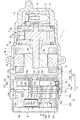
図1は本発明の第1実施形態に係る電動コンプレッサの概略構成を示す正断面図、図2(a)は図1のIIa-IIa線断面図、図2(b)は図1のIIb-IIb線断面図である。図1に示す本実施形態の電動コンプレッサ1は、圧縮機構3を電動モータ5で駆動して冷媒を圧縮するものである。
そして、図1に示すように、本実施形態の電動コンプレッサ1は、圧縮機構3及び電動モータ5の他、これらが収容されるハウジング7(請求項中の本体ハウジングに相当)と、電動モータ5の駆動回路であるインバータ回路9(請求項中の駆動回路に相当)が収容されるインバータケース11と、インバータケース11に収容されるアキュームレータ15とを有している。
電動モータ5は、回転軸5aに取り付けられたロータ5bと、ロータ5bの外側に配置されたステータ5cとを有している。ステータ5cは複数の極に対応したティース(図示せず)を有しており、各ティースにはコイル5dがそれぞれ巻回されている。電動モータ5は、各コイル5dに所定のパターンで電圧を印加することでステータ5cに回転磁界を発生させることで、ロータ5bを回転させる。
圧縮機構3は、一対のサイドブロック3a,3bと、これらによって挟持されたシリンダブロック3cと、シリンダブロック3cの内部に形成された楕円形のシリンダ室3dに収容した円柱状のロータ3eとを有している。圧縮機構3のロータ3eは電動モータ5の回転軸5aと一体に形成されており、ロータ3eの周面には、複数のベーン(図示せず)が出没可能に支持されている。
圧縮機構3のロータ3eが電動モータ5によりシリンダ室3d内で回転されると、ロータ3eの各ベーンがシリンダ室3dの内周面に倣って出没し、ロータ3eと隣り合う2つのベーンとシリンダ室3dとで構成される空間の容積が変化する。そして、空間の容積が増加する間に、サイドブロック3aに形成した吸入口(図示せず)を通じて低圧の冷媒が吸入され、吸入された冷媒が、空間の容積の減少に伴い圧縮される。圧縮された高圧の冷媒は、サイドブロック3bに形成した吐出口(図示せず)から吐出される。
ハウジング7は、一端が閉塞された円筒状を呈している。このハウジング7には圧縮機構3が収容されている。そしてハウジング7の内部は、収容された圧縮機構3によってサイドブロック3bが露出する閉塞側の密閉された吐出室7aと、サイドブロック3aが露出する開口側の吸入室7bとに仕切られている。吸入室7bには電動モータ5が収容されている。そして吸入室7bは、ハウジング7の開口7cに取り付けたインバータケース11によって密閉されている。
圧縮機構3が吐出する圧縮冷媒は、ミスト状の冷凍機油Oを含んでいる。この冷凍機油Oは、吐出室7aの油分離器7dにおいて圧縮冷媒から分離され、吐出室7aの底部の油溜まり部7eに溜まる。油溜まり部7eの冷凍機油Oは、吐出室7a内の冷媒の圧力を利用して、圧縮機構3のサイドブロック3a,3bに設けられた回転軸5aの軸受部(図示せず)に、潤滑油として供給される。
インバータケース11は、第1ケース12と第2ケース13の2つのケース12,13をつなげて構成されている。
インバータケース11の第1ケース12は、フロントアキュームレータ部12cとインバータ回路9が収容される回路収容部12a(請求項中の回路ハウジングに相当)とを、仕切壁12dによって仕切って構成されている。フロントアキュームレータ部12cには、電動コンプレッサ1の外部から吸入室7bに、圧縮機構3によって圧縮する低温低圧の冷媒を吸入する吸入ポート12bが設けられている。
回路収容部12aは、仕切壁12dを底部とする有底の筒状を呈している。回路収容部12aに露出する仕切壁12dの面12e(請求項中の他方の面に相当)には、インバータ回路9の回路基板9aが固定される。回路収容部12aは、その開口12fに取り付けたキャップ12gによって密閉される。
回路基板9aには、インバータ回路9を構成するIGBTやMOSFET等の電力用スイッチング素子9b(請求項中の発熱部品に相当)が実装されている。そして電力用スイッチング素子9bの筐体は、仕切壁12dの面12eの下部に位置する当接部12h(請求項中の当接箇所に相当)に面接触されている。
仕切壁12dの当接部12hを設けた面12eとは反対側の、仕切壁12dのフロントアキュームレータ部12cに露出する面12i(請求項中の一方の面に相当)には、吸入ポート12bが一体に形成されている。
フロントアキュームレータ部12cは、吸入ポート12bの下方に配置した気液分離器12jを有している。気液分離器12jは、吸入ポート12bから吸入された冷媒が衝突する衝突壁12kを有している。
吸入ポート12bから吸入された冷媒には、気相の冷媒と液相の冷媒とが混じっている。さらに、吸入ポート12bから吸入された冷媒には圧縮機構3のサイドブロック3a,3bに設けられた回転軸5aの軸受部(図示せず)に供給されたミスト状の冷凍機油Oが混じっている。
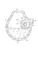
吸入ポート12bからの吸入冷媒が衝突壁12kに衝突すると、液相の冷媒とミスト状の冷凍機油Oが表面に付着する。そして液相の冷媒とミスト状の冷凍機油Oとは、図1のI-I線断面図である図2(a)に示すように、衝突壁12kの表面を伝ってフロントアキュームレータ部12cの底部に流れ落ちて溜まる。
なお、吸入ポート12bとアキュームレータ部15との連通構造をわかりやすくするために、図1は、第1ケース12の上半部のみ、正断面図ではなく図2(a)のフロントアキュームレータ部12cの中心と吸入ポート12bとを結ぶ切断面における断面を示している。
インバータケース11の第2ケース13は、図1に示すように、ハウジング7の開口7cを塞いで吸入室7bを密閉する蓋部13aと、フロントアキュームレータ部12cの開口12lを塞ぎフロントアキュームレータ部12cと協働してアキュームレータ15を構成するリアアキュームレータ部13bとを、断熱壁13cによって仕切って構成されている。断熱壁13cの内部には断熱空間13d(請求項中の断熱部に相当)が設けられており、断熱空間13dには空気や断熱材等の断熱効果を有する流体(図示せず)が充填されている。
フロントアキュームレータ部12cの開口12lをリアアキュームレータ部13bにより塞いで構成されるアキュームレータ15は、液溜まり部15aと気相冷媒通路15b(請求項中の通路に相当)とを有している。液溜まり部15aは、フロントアキュームレータ部12cとリアアキュームレータ部13bとに跨がってインバータケース11の底部側に設けられている。液溜まり部15aには、気液分離器12jの衝突壁12kに衝突して分離された液相成分(液相の冷媒とミスト状の冷凍機油O)が溜まる。
液溜まり部15aは、区画壁12mが気液分離器12jよりも低い高さでフロントアキュームレータ部12cの底部から立設されている。そして液溜まり部15aは、区画壁12mによって仕切壁12dの面12iに隣接する第1アキュームレータ室15cとハウジング7の吸入室7bに隣接する第2アキュームレータ室15dとに区画されている。第1アキュームレータ室15cは、気液分離器12jの直下に配置されていて、気液分離器12jで分離された液相成分(液相の冷媒とミスト状の冷凍機油O)が溜まる。
また、第1アキュームレータ室15cと第2アキュームレータ室15dとは、区画壁12mの下方に形成された貫通孔12nにより連通している。このため、第1アキュームレータ室15cの液面は第2アキュームレータ室15dの液面よりも先に上がるが、第2アキュームレータ室15dの液面もやがて第1アキュームレータ室15cの液面と同じになる。
なお、第1アキュームレータ室15cは、ここに溜まった液相成分(液相の冷媒とミスト状の冷凍機油O)の液面が、仕切壁12dの面12eの当接部12hに対向する仕切壁12dの面12iの部分を常時上回る高さとなるような容量で形成されている。
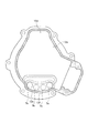
リアアキュームレータ部13bには、気相冷媒通路15bが設けられている。気相冷媒通路15bは、気液分離器12jの衝突壁12kにより液相成分(液相の冷媒とミスト状の冷凍機油O)が分離された後の冷媒の気相成分を吸入室7bに導入するためのものである。気相冷媒通路15bは、両端が開放された中空管体13eを有している。そして中空管体13eは、図1のIIb-IIb線断面図である図2(b)に示すように、一端13fが第2ケース13の上端付近に配置され他端13gが第2ケース13の中央付近に配置された略逆J字状を呈している。
中空管体13eの一端13fは、液溜まり部15aに溜まった液相成分(液相の冷媒とミスト状の冷凍機油O)が流入するのを防ぐために、フロントアキュームレータ部12cの気液分離器12jよりも高い位置に配置されている。また、中空管体13eの他端13gは、図1に示すように、この継手部13hを介して断熱壁13cの開口部13iに接続され、吸入室7bと連通している。
図2(b)に示すように、中空管体13eの両端13f,13g間には、リアアキュームレータ部13bの底部付近で折り返された折り返し部13jが設けられている。この折り返し部13jは、図1に示すように、液溜まり部15aの第2アキュームレータ室15dに溜まった冷凍機油Oの液面よりも十分低い位置に配置されている。
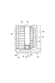
図3の要部拡大断面図に示すように、折り返し部13jには、第2アキュームレータ室15dに溜まった冷凍機油Oを中空管体13e内との圧力差によりミスト状に吸い込むために、小径の戻し孔13kが形成されている。戻し孔13kの周りは、折り返し部13jの外側に配置されたフィルタ13lによって覆われている。このフィルタ13lは、異物が戻し孔13kに入り込むのを防ぐものである。
このように構成された気相冷媒通路15bを有する本実施形態の電動コンプレッサ1によれば、インバータケース11の回路収容部12aに露出する仕切壁12dの面12eの当接部12hに電力用スイッチング素子9bを当接させ、仕切壁12dの面12iにおける当接部12hの裏側箇所に、吸入ポート12bから吸入された冷媒から気液分離器12jで分離された液相成分(液相の冷媒や冷凍機油O)が溜まる液溜まり部15aを設けた。
このため、例えば、不図示の冷凍サイクルの冷凍負荷が少なく吸入ポート12bからの冷媒の吸入量が少なくても、以前からアキュームレータ15の第1アキュームレータ室15cに貯留されている液相の冷媒や冷凍機油Oにより、当接部12hに当接させた電力用スイッチング素子9bを、仕切壁12dを介して十分に冷却することができる。
また、本実施形態の電動コンプレッサ1はアキュームレータ15を内蔵する。このため、電動コンプレッサ1の外部にアキュームレータを設ける場合に比べて、冷凍サイクル側の構成を簡略化することができる。さらに、電動コンプレッサとアキュームレータとの間で支持構造を設ける必要もなくすことができる。
しかも、本実施形態の電動コンプレッサ1では、電動モータ5が収容されるハウジング7の吸入室7bとアキュームレータ15の液溜まり部15aとの間に、インバータケース11の第2ケース13の断熱壁13cが配置される。このことにより、電動モータ5で発生した熱が断熱壁13cで遮断されて液溜まり部15aに伝わりにくくなっている。このため、液溜まり部15aに溜まった液相成分(液相の冷媒や冷凍機油O)の気化による減少で電力用スイッチング素子9bの冷却効率が下がるのを防止することができる。
さらに、アキュームレータ15の液溜まり部15aを区画壁12mによって吸入ポート12bの直下の第1アキュームレータ室15cとその隣の第2アキュームレータ室15dとに区画した。
これによって、電力用スイッチング素子9bを冷却する液相成分(液相の冷媒や冷凍機油O)が溜まる液溜まり部15aの、仕切壁12dの面12iに面する部分の容積を低減されている。このため、反対側の面12eの当接部12hに対応する高さまで液相成分(液相の冷媒や冷凍機油O)の液面を早く届かせることができる。
よって、当接部12hに当接された電力用スイッチング素子9bの液溜まり部15aに溜まった液相成分(液相の冷媒や冷凍機油O)による冷却を効率よく行うことができる。
なお、電動コンプレッサ1の停止中には、吐出室7aと吸入室7bとの冷媒の圧力差により冷媒が圧縮機構3を経て吐出室7aから吸入室7bに逆流する。この逆流により吸入室7bの圧力が上昇すると、気相冷媒通路15bの中空管体13eを介して高圧冷媒が吸入室7bから気液分離器12j側に流入する。
すると、アキュームレータ15から仕切壁12dの面12iにかかる圧力が上昇して仕切壁12dが面12e側に変形し、回路基板9aに対する電力用スイッチング素子9bの半田付け箇所に集中して応力がかかる。
このような応力が半田付け箇所に集中すると、半田付け箇所にクラックが生じたり半田が回路基板9aの導電パターンから剥がれて浮いたりして、電力用スイッチング素子9bと回路基板9aの導電パターンとの間に接続不良が発生する可能性がある。
そこで、吸入室7bから気液分離器12j側への冷媒の逆流を防止する逆止弁を設ける構成としてもよい。
図4は本発明の第1実施形態の変形例に係る電動コンプレッサの概略構成を示す正断面図である。なお、図4においても図1と同様に、吸入ポート12bとアキュームレータ部15との連通構造をわかりやすくするために、第1ケース12の上半部のみ、フロントアキュームレータ部12cの中心と吸入ポート12bとを結ぶ切断面における断面を示している。
そして、図4に示す電動コンプレッサ1では、第2ケース13の断熱壁13cの開口部13iに、吸入室7bから気相冷媒通路15bの中空管体13e側への冷媒の侵入を阻止する逆止弁13mを取り付けている。これにより、吐出室7aから吸入室7bに逆流した高圧冷媒が気液分離器12j側に流入して仕切壁12dが変形するのを防止することができる。
また、吐出室7aから吸入室7bに逆流した高温の高圧冷媒が吸入室7bから気相冷媒通路15bの中空管体13eに流入するのが逆止弁13mによって防がれるので、中空管体13eが高温の高圧冷媒の通過で加熱されてにくい。このため、高温の高圧冷媒の熱がアキュームレータ15の液溜まり部15aに伝わりにくいようにすることができる。よって、液溜まり部15aに溜まった液相成分(液相の冷媒や冷凍機油O)の気化による減少で電力用スイッチング素子9bの冷却効率が下がるのを防止することができる。
なお、電力用スイッチング素子9bの他にも、インバータ回路9中に発熱する素子が存在する場合は、回路収容部12aのできるだけ下方に配置することで、電力用スイッチング素子9bと同様に液溜まり部15aの液相成分(液相の冷媒や冷凍機油O)によって冷却することができる。
図5は本発明の第1実施形態の他の変形例に係る電動コンプレッサの概略構成を示す正断面図である。なお、図5においても図1や図4と同様に、吸入ポート12bとアキュームレータ部15との連通構造をわかりやすくするために、第1ケース12の上半部のみ、フロントアキュームレータ部12cの中心と吸入ポート12bとを結ぶ切断面における断面を示している。
そして、図5に示す第1実施形態の変形例では、インバータ回路9が、電力用スイッチング素子9bに加えて電解コンデンサ9c(請求項中の素子に相当)を発熱する素子として有している。
第1実施形態の電動コンプレッサ1においては、アキュームレータ15の液溜まり部15a(第1アキュームレータ室15c)に、気液分離器12jにおいて冷媒から分離された液相成分(液相の冷媒や冷凍機油O)が自重で落下して溜まる。このため、液溜まり部15aの液相成分(液相の冷媒や冷凍機油O)で冷却する対象は、回路収容部12aのできるだけ下方に配置することが好ましい。
そこで、図5に示す変形例の電動コンプレッサ1では、回路収容部12aの電力用スイッチング素子9bよりもさらに下方に電解コンデンサ9cを配置して、仕切壁12dの面12eに接近させている。
このようにしても、液溜まり部15aの液相成分(液相の冷媒や冷凍機油O)によって冷却された仕切壁12dの面12eとの熱交換により、電解コンデンサ9cを電力用スイッチング素子9bと同様に冷却することができる。
また、インバータ回路9において、複数個の電解コンデンサ9cにおける発熱が専ら大きく、それに比べて他の素子における発熱はさほど大きくない場合は、液相成分(液相の冷媒や冷凍機油O)で冷却する対象を発熱が大きい複数個の電解コンデンサ9cに絞り込む構成としてもよい。
図6は本発明の第1実施形態のさらに他の変形例に係る電動コンプレッサの概略構成を示す正断面図、図7は図6のVII-VII線断面図である。なお、図6においても図1、図4及び図5と同様に、吸入ポート12bとアキュームレータ部15との連通構造をわかりやすくするために、アキュームレータ部15の断面部分の上半部のみ、フロントアキュームレータ部12cの中心と吸入ポート12bとを結ぶ切断面における断面を示している。
そして、図6に示す第1実施形態の変形例では、インバータ回路9が電解コンデンサ9cを複数有しており、それらから、電力用スイッチング素子9bが発する熱よりも高温の熱が発生する。
そこで、図6に示す変形例の電動コンプレッサ1では、図7に示すように、インバータケース11の第1ケース12の回路収容部12aにおける開口12fの円弧状を呈する底部寄りの箇所に、その形状に沿って複数の電解コンデンサ9cを円弧状に並べて配置している。
また、本変形例の電動コンプレッサ1では、吸入した冷媒から分離した液相成分(液相の冷媒や冷凍機油O)によって冷却する複数の電解コンデンサ9cを、回路収容部12aの底部寄りの箇所に集中して配置した。このことから、この電動コンプレッサ1は、図6に示すように、気液分離器を電動コンプレッサ1に内蔵させない構成となっている。
そのため、本変形例の電動コンプレッサ1では、図1、図4、図5を参照して説明した第1実施形態や他の変形例の電動コンプレッサ1でインバータケース11の一部を構成した第2ケース13を省略し、第1ケース12のみでインバータケース11を構成している。したがって、本変形例の電動コンプレッサ1では、ハウジング7の開口7cに、第1ケース12のフロントアキュームレータ部12cの開口12lを取り付けて、吸入室7bを塞いでいる。
そして、吸入ポート12bから吸入された冷媒を吸入室7b内における流動によって気液分離させ、冷媒から分離された液相成分(液相の冷媒や冷凍機油O)を自重により落下させて、吸入室7bの電動モータ5の収容部分の底部にできた液溜まり部15aを、アキュームレータ15としている。
なお、電力用スイッチング素子9bの冷却は、吸入室7bに露出する仕切壁12dの面12iにおける、電力用スイッチング素子9bを当接させた当接部12hの裏側箇所に取り付けたガイド板12pと面12iとの隙間Sを、流速を上げて通過する冷媒によって行う。この隙間Sを冷媒が通過する際に、面12iやガイド板12pの表面と接触することで、冷媒からの液相成分(液相の冷媒や冷凍機油O)の分離も期待することができる。
このように構成された本変形例の電動コンプレッサ1によれば、図1、図4、図5を参照して説明した第1実施形態や他の変形例の電動コンプレッサ1のようなアキュームレータ15を用いて液溜まり部15aに高い液面の液相成分(液相の冷媒や冷凍機油O)を貯めなくても、インバータ回路9の冷却対象の素子を十分に冷却することができる。
図8は本発明の第2実施形態に係る電動コンプレッサの概略構成を示す正断面図、図9は図8のIX-IX線断面図である。図8に示すように、本実施形態の電動コンプレッサ1では、ハウジング7内の構成、即ち、圧縮機構3や電動モータ5、油分離器7d及び油溜まり部7eの構成を、第1実施形態やその変形例の電動コンプレッサ1(図1、図4乃至図6参照)と同じ構成としている。
そして、本実施形態の電動コンプレッサ1では、図8に示すように、インバータケース11の第1ケース12のフロントアキュームレータ部12cではなく第2ケース13のリアアキュームレータ部13bに、吸入ポート13nを設けている。
また、本実施形態の電動コンプレッサ1では、第2ケース13のリアアキュームレータ部13bに気液分離器13oを設けている。そしてこの電動コンプレッサ1では、気液分離器13oを、断熱壁13cから仕切壁12dに向けて水平に突設した中空の円筒部材13p(請求項中の筒部に相当)及びその外側の円筒状の外周壁13qと、上述した吸入ポート13nとを用いて構成している。
なお、図8においては、吸入ポート13nと気液分離器13oとの連通構造をわかりやすくするために、第2ケース13の上半部のみ、リアアキュームレータ部13bの中心と吸入ポート13nとを結ぶ切断面における断面を示している。
そして、円筒部材13pの先端(図8中の左端)は、第1ケース12の仕切壁12dの面12iに間隔をおいて対向している。円筒部材13pの基端(図8中の右端)は、第2ケース13の断熱壁13cの上部に形成した開口部13i(請求項中の貫通孔に相当)に接続され、吸入室7bと連通している。
図8のIX-IX線断面図である図9に示すように、吸入ポート13nは気液分離器13oの円筒部材13pと外周壁13qとの間に形成される円筒状の分離室に接線方向から接続されている。そして、吸入ポート13nから分離室内に吸入された冷媒は、図8に示すように、円筒部材13pの基端側から先端側に向けて分離室内を螺旋状に旋回する旋回流となる。このとき、吸入ポート13nから分離室内への吸入冷媒の流入方向は、円筒部材13pの上方からでもよく、図9に示すように水平方向からでもよい。また、吸入ポート13nから分離室内への吸入冷媒の流入経路は、アキュームレータ15の液溜まり部15aに溜まった液相成分(液相の冷媒や冷凍機油O)の液面よりも上に配置する必要がある。
この吸入冷媒の旋回流が円筒部材13pの先端側に到達するまでの間に、吸入冷媒中の液相の冷媒や冷凍機油Oの液相成分は遠心分離されて外周壁13qに付着する。付着した液相成分は、仕切壁12dの面12iと外周壁13qの先端との隙間を通過し、自重によりアキュームレータ15の液溜まり部15aに流れ落ちて溜まる。
また、吸入冷媒は、その旋回流が分離室内において円筒部材13pや外周壁13qの先端に達し、液相成分が分離されて気相の冷媒となる。この気相の冷媒は、図8に示す円筒部材13pの先端から内部に流入し、円筒部材13pの基端から第2ケース13の断熱壁13cの開口部13iを経てハウジング7の吸入室7bの上部に流入する。
なお、本実施形態の電動コンプレッサ1の構成では、吸入室7bに流入する経路の途中で気相の冷媒に液溜まり部15aから冷凍機油Oを供給することができない。そこで、例えば、第2ケース13の断熱壁13cの下部に戻し孔13kを形成し、吸入室7bに流入した気相の冷媒に液溜まり部15aから冷凍機油Oを供給すればよい。
また、本実施形態では、第1実施形態やその変形例の電動コンプレッサ1における第1ケース12のフロントアキュームレータ部12cから立設した区画壁12mを省略している。しかし、フロントアキュームレータ部12cから区画壁12mを立設してアキュームレータ15の液溜まり部15aを第1アキュームレータ室15cと第2アキュームレータ室15dとに区画してもよい。
このように構成された本実施形態の電動コンプレッサ1では、気液分離器13oの円筒部材13pと外周壁13qとの間に形成される円筒状の分離室内に吸入冷媒の旋回流を発生させ、遠心力により気液分離するため、衝突壁12kに吸入冷媒を単に衝突させて気液分離する先の実施形態と比べて、気液分離器13oをコンパクトに構成しつつ気液分離効率を高めることができる。
本出願は、2015年6月26日に出願された日本国特許出願第2015-128577号に基づく優先権を主張しており、この出願の全内容が参照により本願明細書に組み込まれる。
本発明は、冷媒の圧縮機構を電動モータで駆動する電動コンプレッサにおいて利用することができる。
1 電動コンプレッサ 3 圧縮機構 3a,3b サイドブロック 3c シリンダブロック 3d シリンダ室 3e ロータ 5 電動モータ 5a 回転軸 5b ロータ 5c ステータ 5d コイル 7 ハウジング(本体ハウジング) 7a 吐出室 7b 吸入室 7c ハウジング開口 7d 油分離器 7e 油溜まり部 9 インバータ回路(駆動回路) 9a 回路基板 9b 電力用スイッチング素子(発熱部品) 9c 電解コンデンサ(発熱部品、素子) 11 インバータケース 12 第1ケース 12a 回路収容部(回路ハウジング) 12b,13n 吸入ポート 12c フロントアキュームレータ部 12d 仕切壁 12e 仕切壁面(他方の面) 12f 回路収容部開口 12g キャップ 12h 当接部(当接箇所) 12i 仕切壁面(一方の面) 12j,13o 気液分離器 12k 衝突壁 12m 区画壁 12l フロントアキュームレータ部開口 12n 貫通孔 12p ガイド板 13 第2ケース 13a 蓋部 13b リアアキュームレータ部 13c 断熱壁(壁部) 13d 断熱空間(断熱部) 13e 中空管体 13f 中空管体一端 13g 中空管体他端 13h 継手部 13i 断熱壁開口部(貫通孔) 13j 折り返し部 13k 戻し孔 13l フィルタ 13m 逆止弁 13p 円筒部材(筒部) 13q 外周壁 15 アキュームレータ 15a 液溜まり部 15b 気相冷媒通路(通路) 15c 第1アキュームレータ室 15d 第2アキュームレータ室 O 冷凍機油 S 隙間
Claims (10)
- 冷媒を圧縮する圧縮機構(3)と、
前記圧縮機構(3)を駆動する電動モータ(5)と、
前記圧縮機構(3)及び電動モータ(5)が収容された本体ハウジング(7)と、
前記電動モータ(5)の駆動回路(9)が収容され、仕切壁(12d)によって前記本体ハウジング(7)と仕切られた回路ハウジング(12a)と、
前記本体ハウジング(7)に露出する前記仕切壁(12d)の一方の面(12i)側に設けられ、前記本体ハウジング(7)の外部から内部に吸入される冷媒の液相成分が貯留される液溜まり部(15a)と、
前記回路ハウジング(12a)に露出する前記仕切壁(12d)の他方の面(12e)のうち、前記液溜まり部(15a)に対向する当接箇所(12h)に当接された、前記駆動回路(9)の発熱部品(9b)と、
を備える電動コンプレッサ(1)。 - 前記液溜まり部(15a)は、前記一方の面(12i)側における前記回路ハウジング(12a)の底部寄りに設けられており、前記発熱部品(9b)は、前記他方の面(12e)における前記回路ハウジング(12a)の底部寄りに設けられている請求項1記載の電動コンプレッサ(1)。
- 前記発熱部品(9b)は複数の素子(9c)を含んでおり、これら複数の素子(9c)は前記回路ハウジング(12a)の底部の外形に沿った形状に並べて配置されている請求項2記載の電動コンプレッサ(1)。
- 前記液溜まり部(15a)は、前記本体ハウジング(7)の外部から内部に吸入される冷媒のアキュームレータ(15)に設けられている請求項1~3のいずれか1項に記載の電動コンプレッサ(1)。
- 前記アキュームレータ(15)は、前記一方の面(12i)に隣接した第1アキュームレータ室(15c)と、該第1アキュームレータ室(15c)と区画壁(12m)により区画された第2アキュームレータ室(15d)とを有しており、前記回路ハウジング(12a)に形成された吸入ポート(12c)を通過して前記本体ハウジング(7)の外部から内部に吸入された冷媒が貯留される前記第1アキュームレータ室(15c)によって前記液溜まり部(15a)が構成されている請求項4記載の電動コンプレッサ(1)。
- 前記第1アキュームレータ室(15c)は、前記吸入ポート(12c)の下方に配置されている請求項5記載の電動コンプレッサ(1)。
- 前記液溜まり部(15a)と、該液溜まり部(15a)に隣り合う前記本体ハウジング(7)の前記電動モータ(5)の収容空間との間に、断熱部(13d)を有する断熱壁(13c)が介設されている請求項1~6のいずれか1項に記載の電動コンプレッサ(1)。
- 前記本体ハウジング(7)の外部から内部に吸入される冷媒から液相成分を分離する遠心分離式の気液分離器(13o)をさらに備え、該気液分離器(13o)により分離された液相成分が前記液溜まり部(15a)に貯留される請求項1~7のいずれか1項に記載の電動コンプレッサ(1)。
- 前記液溜まり部(15a)は、該液溜まり部(15a)に隣り合う前記本体ハウジング(7)の前記電動モータ(5)の収容空間との間に介設された壁部(13c)により該収容空間と仕切られており、前記気液分離器(13o)は、前記壁部(13c)の貫通孔(13i)と連通し該壁部(13c)から前記液溜まり部(15a)の上方に延出する筒部(13p)と、前記本体ハウジング(7)の外部から内部に吸入される冷媒を前記筒部(13p)の外周に導入し該筒部(13p)の外周に冷媒の旋回流を形成する吸入ポート(13n)とを有している請求項8記載の電動コンプレッサ(1)。
- 前記本体ハウジング(7)の外部から内部に吸入されて前記液溜まり部(15a)に貯留される液相成分が分離された冷媒を前記本体ハウジング(7)の前記電動モータ(5)の収容空間に導く通路(15b)に、該電動モータ(5)の収容空間からの冷媒の逆流を阻止する逆止弁(13m)が設けられている請求項1~9のいずれか1項に記載の電動コンプレッサ(1)。
Applications Claiming Priority (2)
| Application Number | Priority Date | Filing Date | Title |
|---|---|---|---|
| JP2015128577A JP6514585B2 (ja) | 2015-06-26 | 2015-06-26 | 電動コンプレッサ |
| JP2015-128577 | 2015-06-26 |
Publications (1)
| Publication Number | Publication Date |
|---|---|
| WO2016208283A1 true WO2016208283A1 (ja) | 2016-12-29 |
Family
ID=57585489
Family Applications (1)
| Application Number | Title | Priority Date | Filing Date |
|---|---|---|---|
| PCT/JP2016/063802 Ceased WO2016208283A1 (ja) | 2015-06-26 | 2016-05-10 | 電動コンプレッサ |
Country Status (2)
| Country | Link |
|---|---|
| JP (1) | JP6514585B2 (ja) |
| WO (1) | WO2016208283A1 (ja) |
Families Citing this family (3)
| Publication number | Priority date | Publication date | Assignee | Title |
|---|---|---|---|---|
| JP6992778B2 (ja) * | 2019-02-28 | 2022-01-13 | 株式会社デンソー | 圧縮機 |
| JP7652063B2 (ja) * | 2021-12-27 | 2025-03-27 | 株式会社豊田自動織機 | 電動圧縮機 |
| CN116803709A (zh) * | 2023-04-21 | 2023-09-26 | 浙江三花智能控制股份有限公司 | 集成装置 |
Citations (2)
| Publication number | Priority date | Publication date | Assignee | Title |
|---|---|---|---|---|
| JP2014109250A (ja) * | 2012-12-04 | 2014-06-12 | Calsonic Kansei Corp | 電動コンプレッサ |
| JP2015081539A (ja) * | 2013-10-22 | 2015-04-27 | サンデン株式会社 | 電動圧縮機 |
Family Cites Families (1)
| Publication number | Priority date | Publication date | Assignee | Title |
|---|---|---|---|---|
| JP2007309109A (ja) * | 2006-05-16 | 2007-11-29 | Calsonic Kansei Corp | 電動コンプレッサ |
-
2015
- 2015-06-26 JP JP2015128577A patent/JP6514585B2/ja not_active Expired - Fee Related
-
2016
- 2016-05-10 WO PCT/JP2016/063802 patent/WO2016208283A1/ja not_active Ceased
Patent Citations (2)
| Publication number | Priority date | Publication date | Assignee | Title |
|---|---|---|---|---|
| JP2014109250A (ja) * | 2012-12-04 | 2014-06-12 | Calsonic Kansei Corp | 電動コンプレッサ |
| JP2015081539A (ja) * | 2013-10-22 | 2015-04-27 | サンデン株式会社 | 電動圧縮機 |
Also Published As
| Publication number | Publication date |
|---|---|
| JP2017008910A (ja) | 2017-01-12 |
| JP6514585B2 (ja) | 2019-05-15 |
Similar Documents
| Publication | Publication Date | Title |
|---|---|---|
| US7473079B2 (en) | Electric compressor with inverter | |
| US9410547B2 (en) | Compressor with oil separator and refrigeration device including the same | |
| CN102713288B (zh) | 压缩机 | |
| CN104822941B (zh) | 电动压缩机 | |
| JP5897117B2 (ja) | 冷媒圧縮機および冷凍サイクル機器 | |
| CN103635696B (zh) | 多汽缸旋转式压缩机和制冷循环装置 | |
| JP6479206B2 (ja) | ロータリ圧縮機 | |
| CN104854780A (zh) | 电动压缩机 | |
| WO2015025514A1 (ja) | 冷凍装置 | |
| JP6514585B2 (ja) | 電動コンプレッサ | |
| JP2015038406A (ja) | 冷凍装置 | |
| CN101936292A (zh) | 压缩机 | |
| JP2008232134A (ja) | 電動コンプレッサ | |
| JP6023973B2 (ja) | 電動圧縮機 | |
| JP4529973B2 (ja) | 電動圧縮機 | |
| JP6514584B2 (ja) | 電動コンプレッサ | |
| JP6896147B2 (ja) | 圧縮機 | |
| JP2005146862A (ja) | 電動圧縮機 | |
| JP2017198159A (ja) | 電動圧縮機 | |
| JP2016223373A (ja) | 電動コンプレッサ | |
| JP2014171333A (ja) | モータおよび圧縮機 | |
| JP2005171943A (ja) | アンモニア冷媒用密閉形圧縮機 | |
| JP2017008908A (ja) | 気体圧縮機 | |
| JP6772934B2 (ja) | 電動圧縮機 | |
| JP2014134132A (ja) | 圧縮機 |
Legal Events
| Date | Code | Title | Description |
|---|---|---|---|
| 121 | Ep: the epo has been informed by wipo that ep was designated in this application |
Ref document number: 16814054 Country of ref document: EP Kind code of ref document: A1 |
|
| DPE1 | Request for preliminary examination filed after expiration of 19th month from priority date (pct application filed from 20040101) | ||
| NENP | Non-entry into the national phase |
Ref country code: DE |
|
| 122 | Ep: pct application non-entry in european phase |
Ref document number: 16814054 Country of ref document: EP Kind code of ref document: A1 |