WO2016204224A1 - 歯ブラシハンドルおよび歯ブラシ - Google Patents
歯ブラシハンドルおよび歯ブラシ Download PDFInfo
- Publication number
- WO2016204224A1 WO2016204224A1 PCT/JP2016/067930 JP2016067930W WO2016204224A1 WO 2016204224 A1 WO2016204224 A1 WO 2016204224A1 JP 2016067930 W JP2016067930 W JP 2016067930W WO 2016204224 A1 WO2016204224 A1 WO 2016204224A1
- Authority
- WO
- WIPO (PCT)
- Prior art keywords
- columnar
- handle
- head
- toothbrush
- side hinge
- Prior art date
- Legal status (The legal status is an assumption and is not a legal conclusion. Google has not performed a legal analysis and makes no representation as to the accuracy of the status listed.)
- Ceased
Links
Images




Classifications
-
- A—HUMAN NECESSITIES
- A46—BRUSHWARE
- A46B—BRUSHES
- A46B5/00—Brush bodies; Handles integral with brushware
-
- A—HUMAN NECESSITIES
- A46—BRUSHWARE
- A46B—BRUSHES
- A46B5/00—Brush bodies; Handles integral with brushware
- A46B5/002—Brush bodies; Handles integral with brushware having articulations, joints or flexible portions
- A46B5/0054—Brush bodies; Handles integral with brushware having articulations, joints or flexible portions designed to allow relative positioning of the head to body
- A46B5/0075—Brush bodies; Handles integral with brushware having articulations, joints or flexible portions designed to allow relative positioning of the head to body being adjustable and stable during use
-
- A—HUMAN NECESSITIES
- A46—BRUSHWARE
- A46B—BRUSHES
- A46B5/00—Brush bodies; Handles integral with brushware
- A46B5/002—Brush bodies; Handles integral with brushware having articulations, joints or flexible portions
- A46B5/0054—Brush bodies; Handles integral with brushware having articulations, joints or flexible portions designed to allow relative positioning of the head to body
- A46B5/0062—Brush bodies; Handles integral with brushware having articulations, joints or flexible portions designed to allow relative positioning of the head to body being flexible or resilient during use
-
- A—HUMAN NECESSITIES
- A46—BRUSHWARE
- A46B—BRUSHES
- A46B5/00—Brush bodies; Handles integral with brushware
- A46B5/002—Brush bodies; Handles integral with brushware having articulations, joints or flexible portions
- A46B5/0054—Brush bodies; Handles integral with brushware having articulations, joints or flexible portions designed to allow relative positioning of the head to body
- A46B5/0091—Brush bodies; Handles integral with brushware having articulations, joints or flexible portions designed to allow relative positioning of the head to body promoting relative motion during use
-
- A—HUMAN NECESSITIES
- A46—BRUSHWARE
- A46B—BRUSHES
- A46B2200/00—Brushes characterized by their functions, uses or applications
- A46B2200/10—For human or animal care
- A46B2200/1066—Toothbrush for cleaning the teeth or dentures
Definitions
- the present invention relates to a toothbrush handle and a toothbrush.
- This application claims priority based on Japanese Patent Application No. 2015-123742 filed in Japan on June 19, 2015, the contents of which are incorporated herein by reference.
- Japanese Patent Application Laid-Open No. H10-228707 discloses a nigiri and a head (head) for the purpose of maintaining the action of the hair at a substantially constant angle with respect to the geometric axis of the toothbrush nail (handle part).
- a toothbrush in which a neck (neck) connecting the two parts is formed by two vertical beams is described.
- One aspect of the present invention is made in view of the above problems, and a toothbrush handle that easily maintains a constant angle of the head portion with respect to the handle portion regardless of the direction of the force applied to the head portion, and One object is to provide a toothbrush having such a toothbrush handle.
- One aspect of the toothbrush handle of the present invention is a toothbrush handle that supports a head portion having a flocking surface on which a plurality of hair bundles are implanted, the handle portion extending in a first direction, the handle portion, and the head A neck portion that connects to the head portion, and the neck portion includes a plurality of columnar portions extending from the handle portion to the head portion, and the plurality of columnar portions include a first columnar portion and a second columnar portion.
- a third columnar part wherein the first columnar part and the second columnar part are arranged along a second direction orthogonal to the first direction, and the third columnar part is In the third direction orthogonal to the first direction and the second direction, the first columnar part and the second columnar part are at different positions.
- the columnar part includes a main body part, a handle part side hinge part that connects the main body part and the handle part, and a head part side hinge part that connects the main body part and the head part, At least a part of the handle part side hinge part and at least a part of the head part side hinge part have a dimension in the second direction and a dimension in the third direction, the dimension in the second direction in the main body part, and the It is good also as a structure smaller than the dimension of 3 directions.
- the cross-sectional shape orthogonal to the extending direction of the columnar part in the handle part side hinge part and the head part side hinge part may be a circular shape.
- the cross-sectional shape perpendicular to the extending direction of the columnar part in the main body part may be a circular shape.
- the handle part side hinge part and the head part side hinge part have a plate shape having a main surface parallel to a surface including the first direction and the second direction, and the handle part side hinge part and the head part side It is good also as a structure by which the recessed part dented in the said 2nd direction is provided in the edge part of the both sides of the said 2nd direction in a hinge part.
- the neck portion may include a covering portion that connects the columnar portions and covers at least a part of the surface of the columnar portion, and the hardness of the covering portion may be smaller than the hardness of the columnar portion.
- the covering portion may cover the entire surface of the columnar portion.
- the covering portion may cover a part of the surface of the columnar part, and the other part of the surface of the columnar part may be exposed to the outside.
- the plurality of columnar portions may be arranged on a predetermined virtual circle when viewed in the extending direction of the neck portion and provided at equal intervals along the circumferential direction of the virtual circle.
- the third columnar part may be configured to be at a position different from the first columnar part and the second columnar part in the second direction.
- One aspect of the toothbrush of the present invention includes the toothbrush handle described above and the head portion supported by the toothbrush handle, wherein the flocked surface is perpendicular to the third direction. To do.
- a toothbrush handle that easily maintains a constant angle of the head portion with respect to the handle portion regardless of the direction of the force applied to the head portion, and a toothbrush provided with such a toothbrush handle.
- an XYZ coordinate system is appropriately shown as a three-dimensional orthogonal coordinate system.
- the X-axis direction (second direction) is a direction parallel to the short direction of the toothbrush 10 shown in FIG. 1, that is, the up-down direction in FIG.
- the Y-axis direction (first direction) is a direction parallel to the longitudinal direction of the toothbrush 10 shown in FIG. 1, that is, the left-right direction in FIG.
- the Z-axis direction (third direction) is a direction orthogonal to both the X-axis direction and the Y-axis direction.
- the X-axis direction may be simply referred to as the short direction
- the Y-axis direction may be simply referred to as the longitudinal direction
- the Z-axis direction may be simply referred to as the thickness direction.
- FIG. 1 is a plan view, that is, a view seen from the + Z side to the ⁇ Z side.
- FIG. 2 is a side view, that is, a view seen in the X-axis direction.
- 3 is a sectional view taken along line III-III in FIG. 4 is a cross-sectional view taken along the line IV-IV in FIG.
- FIG. 5 is a perspective view showing a portion of the toothbrush 10.
- the toothbrush 10 includes a head portion 13 and a toothbrush handle 14.
- the toothbrush handle 14 is a handle for supporting the head portion 13, and the head portion 13 is supported by the toothbrush handle 14.
- the head unit 13 includes a head main body unit 15 and a hair bundle group 20 including a plurality of hair bundles 20a.
- the head main body 15 extends along the longitudinal direction (Y-axis direction).
- the head main body 15 has a flocked surface 15a on which a plurality of hair bundles 20a are implanted.
- the flocked surface 15a is perpendicular to the thickness direction (Z-axis direction, third direction). As shown in FIG. 2, the plurality of hair bundles 20a extend from the flocked surface 15a to one side in the thickness direction (+ Z side).
- the toothbrush handle 14 is connected to one side ( ⁇ Y side) in the longitudinal direction of the head portion 13.
- the toothbrush handle 14 supports the head unit 13.
- the toothbrush handle 14 includes a handle portion 11 and a neck portion 12.
- the handle portion 11 is a portion to be gripped in the toothbrush 10.
- the handle portion 11 extends in the longitudinal direction (Y-axis direction, first direction).
- the neck portion 12 connects the handle portion 11 and the head portion 13. Thereby, the handle
- the neck portion 12 has a plurality of columnar portions and a covering portion 30.
- the plurality of columnar portions include a first columnar portion 41, a second columnar portion 42, and a third columnar portion 43.
- the handle portion 11, the plurality of columnar portions, and the head main body portion 15 are, for example, a single member.
- the first columnar part 41, the second columnar part 42, and the third columnar part 43 extend from the handle part 11 in the longitudinal direction (Y-axis direction, first direction).
- the first columnar part 41, the second columnar part 42, and the third columnar part 43 extend from the handle part 11 to the head part 13. More specifically, the first columnar section 41, the second columnar section 42, and the third columnar section 43 are arranged on the handle section 11 side of the head main body section 15 from the end of the handle section 11 on the head section 13 side (+ Y side). Extends to the ( ⁇ Y side) end. That is, in the state shown in FIGS. 1 and 2, the first columnar part 41, the second columnar part 42, and the third columnar part 43 extend along the longitudinal direction (Y-axis direction).
- the first columnar portion 41 and the second columnar portion 42 have a lateral direction (X-axis direction, second direction) orthogonal to the longitudinal direction (Y-axis direction, first direction). Line up along. That is, the first columnar part 41 and the second columnar part 42 are at the same position in the thickness direction (Z-axis direction).
- the third columnar portion 43 is formed in the thickness direction (Z-axis direction, third direction) orthogonal to the longitudinal direction (Y-axis direction) and the short-side direction (X-axis direction).
- the first columnar part 41 and the second columnar part 42 are in different positions.
- the third columnar portion 43 is located on the opposite side ( ⁇ Z side) to the flocked surface 15a in the thickness direction with respect to the first columnar portion 41 and the second columnar portion.
- the third columnar portion 43 is in a position different from the first columnar portion 41 and the second columnar portion 42 in the short direction (X-axis direction, second direction).
- the third columnar portion 43 is located between the first columnar portion 41 and the second columnar portion 42 when viewed in the thickness direction (Z-axis direction).
- the first columnar portion 41, the second columnar portion 42, and the third columnar portion 43 do not overlap each other when viewed in the thickness direction.
- a plurality of columnar portions that is, the first columnar portion 41, the second columnar portion 42, and the third columnar portion 43 are in the direction in which the neck portion 12 extends, in the example of FIG. When viewed in the axial direction, it is located on a predetermined virtual circle C1.
- the 1st columnar part 41, the 2nd columnar part 42, and the 3rd columnar part 43 are provided at equal intervals along the circumferential direction of the virtual circle C1.
- the center of the third columnar portion 43 is located, for example, at the same position as the center CP of the virtual circle C1 in the short direction (X-axis direction).
- the first columnar portion 41, the second columnar portion 42, and the third columnar portion 43 have the same configuration except for the position where they are arranged. Therefore, in the following description, the first columnar portion 41 is representatively represented. There may only be explained.
- the first columnar part 41 includes a main body part 41a, a handle part side hinge part 41b, and a head part side hinge part 41c.
- the main body 41 a has a columnar shape extending in the longitudinal direction (Y-axis direction). That is, as shown in FIG. 4, the shape of the cross section orthogonal to the extending direction (Y-axis direction) of the first columnar portion 41 in the main body portion 41a is a circular shape.
- the handle part side hinge part 41 b connects the main body part 41 a and the handle part 11.
- the handle part side hinge part 41 b has a shape in which the center of the cylinder is constricted. That is, as shown in FIG. 4, in this embodiment, the shape of the cross section orthogonal to the direction in which the first columnar portion 41 extends in the handle portion side hinge portion 41b is a circular shape.
- the diameter D2 of the handle part side hinge part 41b is the smallest in the center in the longitudinal direction (Y-axis direction) of the handle part side hinge part 41b, and increases as the distance from the center in the longitudinal direction increases to both sides in the longitudinal direction ( ⁇ Y side).
- a diameter D2 at both ends in the longitudinal direction of the handle part side hinge part 41b is the same as the diameter D1 of the main body part 41a. That is, the diameter D2 of the handle part side hinge part 41b is smaller than the diameter D1 of the main body part 41a except for the ends on both sides in the longitudinal direction.
- the handle portion side hinge 41b has a short dimension (X-axis direction, second direction) and a thickness direction (Z-axis direction, third direction) that are short in the main body 41a. It is smaller than the dimension in the hand direction and the dimension in the thickness direction.
- the dimension of the handle part side hinge part 41b excluding the ends on both sides in the longitudinal direction is smaller than the dimension of the main body part 41a in all directions orthogonal to the longitudinal direction (Y-axis direction).
- the head part side hinge part 41 c connects the main body part 41 a and the head part 13. More specifically, the head portion side hinge portion 41 c connects the main body portion 41 a and the head main body portion 15.
- the other structure of the head part side hinge part 41c is the same as that of the handle part side hinge part 41b. That is, at least a part of the head part side hinge part 41c is smaller in dimensions in the short side direction (X-axis direction) and in the thickness direction (Z-axis direction) than the main body part 41a.
- the shape of the cross section orthogonal to the extending direction of the first columnar part 41 in the head part side hinge part 41c is a circular shape.
- the second columnar part 42 includes a main body part 42a, a handle part side hinge part 42b, and a head part side hinge part 42c.
- the third columnar part 43 includes a main body part 43a, a handle part side hinge part 43b, and a head part side hinge part 43c.
- the configurations of the main body portions 42a and 43a are the same as the configuration of the main body portion 41a.
- the structure of the handle part side hinge parts 42b and 43b is the same as the structure of the handle part side hinge part 41b.
- the configuration of the head portion side hinge portions 42c and 43c is the same as the configuration of the head portion side hinge portion 41c.
- the first columnar portion 41 is made of, for example, a hard resin.
- the hard resin include polypropylene (PP: Polypropylene), polyoxymethylene (POM), polybutylene terephthalate (PBT), polyethylene terephthalate (PET): Polyethylene terephthalate (PET). Terephthalate), a resin (PCTA resin) in which a part of the acid component of PCT is replaced with isopropyl alcohol (IPA: Isopropyl Alcohol).
- the hard resin forming the first columnar portion 41 is, for example, PBT or POM. This is because PBT and POM are excellent in fatigue strength.
- the hardness of the hard resin forming the first columnar part 41 is, for example, 70 degrees or more and 90 degrees or less.
- the hardness of the resin is a value when measured with a type A durometer based on JIS K 6253-3: 2012.
- the covering portion 30 extends from the handle portion 11 to the head portion 13. More specifically, the covering portion 30 extends from an end portion on the head portion 13 side (+ Y side) of the handle portion 11 to an end portion on the handle portion 11 side ( ⁇ Y side) of the head main body portion 15. As shown in FIGS. 1 to 3, in the present embodiment, the covering portion 30 has a cylindrical shape extending in the longitudinal direction (Y-axis direction).
- the covering portion 30 connects the columnar portions, that is, the first columnar portion 41, the second columnar portion 42, and the third columnar portion 43.
- the covering part 30 covers at least a part of the surface of the first columnar part 41, at least a part of the surface of the second columnar part 42, and at least a part of the surface of the third columnar part 43.
- the covering portion 30 covers the entire surface of the first columnar portion 41, the entire surface of the second columnar portion 42, and the entire surface of the third columnar portion 43. That is, in the present embodiment, the entire first columnar portion 41, the entire second columnar portion 42, and the entire third columnar portion 43 are embedded in the covering portion 30.
- the cross-sectional shape orthogonal to the direction (Y-axis direction) in which the neck portion 12 of the covering portion 30 extends in the present embodiment is, for example, a circular shape.
- the center of the cross section of the covering portion 30 coincides with the center CP of the virtual circle C1.
- the hardness of the covering portion 30 is smaller than the hardness of the first columnar portion 41.
- the covering portion 30 is made of a soft resin, for example.
- the soft resin is, for example, a thermoplastic elastomer (TPE: Thermoplastic Elastomers).
- TPE thermoplastic elastomer
- the hardness of the soft resin forming the covering portion 30 is, for example, 25 degrees or more and 65 degrees or less.
- the hardness of the covering portion 30 can be determined, for example, according to the repulsive force during brushing that the user likes.
- the neck portion 12 has three columnar portions, that is, a first columnar portion 41, a second columnar portion 42, and a third columnar portion 43.
- the 1st columnar part 41 and the 2nd columnar part 42 are located in a line in the transversal direction, and the 3rd columnar part 43 exists in the position different from the 1st columnar part 41 and the 2nd columnar part 42 in the thickness direction. Therefore, in any direction orthogonal to the longitudinal direction, at least two of the first columnar portion 41, the second columnar portion 42, and the third columnar portion 43 are at different positions. In other words, the first columnar part 41, the second columnar part 42, and the third columnar part 43 are not at the same position in any direction orthogonal to the longitudinal direction.
- the structure similar to the parallel link mechanism is formed by at least two columnar portions, the head main body portion 15 and the handle portion 11. It is formed. Therefore, the neck portion 12 is deformed while maintaining the relative angle between the head main body portion 15 and the handle portion 11 even when a force is applied to the head portion 13 in any direction orthogonal to the longitudinal direction.
- Cheap As a result, it is possible to suppress the relative angle between the head portion 13 and the handle portion 11 from changing.
- the toothbrush handle 14 that easily maintains the angle of the head portion 13 with respect to the handle portion 11 regardless of the direction of the force applied to the head portion 13, and such a toothbrush handle 14 are provided.
- a toothbrush 10 is obtained.
- FIGS. 6 and 7 are explanatory diagrams for explaining the effect of the present embodiment.
- FIG. 6 shows a case where the toothbrush 10 according to the present embodiment is brushed by moving in the longitudinal direction (Y-axis direction).
- FIG. 7 shows a case where the toothbrush 10 according to this embodiment is brushed by moving in the short direction (X-axis direction).
- the toothbrush 10 when the toothbrush 10 is moved in the short direction (X-axis direction), for example, any one of the first columnar portion 41, the second columnar portion 42, and the third columnar portion 43 is used.
- the head main body portion 15 and the handle portion 11 form a structure similar to the parallel link mechanism.
- the longitudinal direction of the head main body portion 15 is suppressed from being inclined with respect to the longitudinal direction of the handle portion 11. Therefore, the head unit 13 can be moved in parallel with the tooth row T in the short direction (X-axis direction), and the tooth row T can be brushed appropriately.
- the first columnar part 41 includes the handle part side hinge part 41b and the head part side hinge part 41c. Therefore, the first columnar portion 41 is more likely to operate in the same manner as the link constituting the parallel link mechanism by bending the handle portion side hinge portion 41b and the head portion side hinge portion 41c. That is, even when the angle of the neck portion 12 changes, the relative angle between the head portion 13 and the handle portion 11 can be more easily maintained.
- Brushing as shown in FIGS. 6 and 7, that is, brushing for moving the toothbrush 10 in the longitudinal direction (Y-axis direction) and brushing for moving the toothbrush 10 in the short-side direction (X-axis direction) are particularly easily performed. Therefore, it is particularly required that the relative angle between the head portion 13 and the handle portion 11 does not change when brushing as shown in FIGS. 6 and 7 is performed.
- At least a part of the handle part side hinge part 41b and at least a part of the head part side hinge part 41c have a dimension in the short side direction (X-axis direction) and a thickness direction (Z
- the dimension in the axial direction is smaller than the dimension in the lateral direction and the dimension in the thickness direction of the main body 41a. Therefore, the handle part side hinge part 41b and the head part side hinge part 41c are easily bent in the lateral direction and the thickness direction.
- the head portion 13, the neck portion 12, and the handle portion 11 are more likely to operate similarly to the parallel link mechanism. Therefore, according to this embodiment, when performing brushing as shown in FIGS. 6 and 7, it is possible to further suppress the relative angle between the head portion 13 and the handle portion 11 from changing.
- the shape of the cross section orthogonal to the direction in which the first columnar part 41 extends in the handle part side hinge part 41b and the head part side hinge part 41c is circular. Therefore, the handle part side hinge part 41b and the head part side hinge part 41c are easily bent in any direction orthogonal to the direction in which the first columnar part 41 extends. The same applies to the second columnar portion 42 and the third columnar portion 43. As a result, even if a force in any direction orthogonal to the longitudinal direction (Y-axis direction) is applied to the head portion 13, the head body portion 15, the neck portion 12, and the handle portion 11 are more parallel links. Easy to operate like the mechanism.
- the 1st columnar part 41, the 2nd columnar part 42, and the 3rd columnar part 43 are connected by the coating
- the covering portion 30 has a lower hardness than the first columnar portion 41. Therefore, it is difficult to inhibit the handle part side hinge part 41b and the head part side hinge part 41c of the first columnar part 41 from being deformed.
- the covering portion 30 covers the entire surface of the first columnar portion 41. Therefore, even if the first columnar part 41 is damaged, it is possible to suppress a part of the first columnar part 41 from falling off.
- the first columnar portion 41, the second columnar portion 42, and the third columnar portion 43 are located on the virtual circle C1 when viewed in the extending direction of the neck portion 12, and Are provided at equal intervals along the circumferential direction of the virtual circle C1. Therefore, in any direction orthogonal to the longitudinal direction (Y-axis direction), a structure similar to the parallel link mechanism including the columnar portions, the head main body portion 15 and the handle portion 11 is easily formed stably. Moreover, it is easy to improve the strength of the neck portion 12 evenly in any direction orthogonal to the longitudinal direction.
- the third columnar portion 43 is located at a position different from the first columnar portion 41 and the second columnar portion 42 in the short side direction (X-axis direction). Therefore, each columnar part can be formed using a mold 50 as shown in FIG. FIG. 8 is a view showing a mold 50 for manufacturing the toothbrush 10.
- the mold 50 includes a first mold 51 and a second mold 52.
- the first mold 51 has a first molding recess 51a, a second molding recess 51b, and a third molding recess 51c.
- the first molding recess 51a, the second molding recess 51b, and the third molding recess 51c are recessed on one side in the thickness direction (+ Z side).
- the second mold 52 has a first molding recess 52a, a second molding recess 52b, and a third molding recess 52c.
- the first molding recess 52a, the second molding recess 52b, and the third molding recess 52c are recessed on the other side in the thickness direction ( ⁇ Z side).
- the first molding space 53, the second molding space 54, and the third molding space 55 are formed by combining the first mold 51 and the second mold 52 in the thickness direction (Z-axis direction).
- the first molding space 53 is formed by the first molding recess 51a and the first molding recess 52a.
- the second molding space 54 is formed by the second molding recess 51b and the second molding recess 52b.
- the third molding space 55 is formed by the third molding recess 51c and the third molding recess 52c.
- the first columnar portion 41 is molded by pouring resin into the first molding space 53.
- the second columnar portion 42 is molded.
- the third columnar portion 43 is molded.
- the first columnar portion 41, the second columnar portion 42, and the third columnar portion 43 are located at different positions in the short direction (X-axis direction).
- Three columnar portions can be formed at a time using a mold 50 including two parts, that is, a first mold 51 and a second mold 52. Therefore, according to this embodiment, the structure of the metal mold
- the following configuration can also be adopted.
- the same configurations as those described above may be omitted by appropriately attaching the same reference numerals.
- the direction in which the first columnar part 41 extends, the direction in which the second columnar part 42 extends, and the direction in which the third columnar part 43 extends may not be strictly parallel.
- the extending directions of the respective columnar portions may be inclined with respect to each other within a range of 10 ° or less from directions parallel to each other.
- first columnar part 41, the second columnar part 42, and the third columnar part 43 do not have to be located at equal intervals in the circumferential direction on the virtual circle C1. In the present embodiment, the first columnar part 41, the second columnar part 42, and the third columnar part 43 may not be located on the virtual circle C1.
- the direction (second direction) in which the first columnar part 41 and the second columnar part 42 are arranged is the direction parallel to the short direction of the toothbrush 10, but is not limited thereto.
- the direction in which the first columnar portion 41 and the second columnar portion 42 are arranged may be any direction orthogonal to the longitudinal direction. Accordingly, the direction in which the first columnar part 41 and the second columnar part 42 are arranged and the direction orthogonal to the longitudinal direction of the toothbrush 10 (third direction) may not be perpendicular to the flocked surface 15a.
- FIG. 9 is a cross-sectional view showing a toothbrush 110 which is another example of the present embodiment.
- the toothbrush 110 includes a toothbrush handle 114.
- the toothbrush handle 114 has a neck portion 112.
- the neck portion 112 includes a first columnar portion 41, a second columnar portion 42, a third columnar portion 43, and a covering portion 130.
- the covering part 130 covers a part of the surface of the first columnar part 41, a part of the surface of the second columnar part 42, and a part of the surface of the third columnar part 43.
- the diameter of the covering portion 130 is smaller than the diameter of the covering portion 30 shown in FIG.
- Other configurations of the covering portion 130 are the same as the configurations of the covering portion 30 shown in FIG.
- the other part of the surface of the first columnar part 41, the other part of the surface of the second columnar part 42, and the other part of the surface of the third columnar part 43 are exposed to the outside.
- the other part of the surface of each columnar part is the entire part other than the part covered by the covering part 130 in the surface of each columnar part, or the part other than the part covered by the covering part 130 in the surface of each columnar part It is a part of the part. In this embodiment, the whole part other than the part covered with the coating
- the neck portion 112 can be easily thinned. Moreover, since the quantity of the material which forms the coating
- the number of columnar portions is not particularly limited as long as the columnar portions include at least the first columnar portion, the second columnar portion, and the third columnar portion. For example, as shown in FIG. Moreover, four or more may be sufficient. As the number of columnar portions is larger, the same structure as the parallel link is more stably formed stably in any direction orthogonal to the longitudinal direction (Y-axis direction).
- FIG. 10 is a cross-sectional view showing a toothbrush 210 which is another example of the present embodiment.
- the toothbrush 210 includes a toothbrush handle 214.
- the toothbrush handle 214 has a neck portion 212.
- the neck part 212 includes five columnar parts 241, 242, 243, 244, 245 and a covering part 30.
- the five columnar parts 241 to 245 are located on a predetermined virtual circle C2 when viewed in the Y-axis direction.
- the columnar portions 241 to 245 are provided at equal intervals along the circumferential direction of the virtual circle C2. In this configuration, when any two of the columnar portions 241 to 245 are the first columnar portion and the second columnar portion, the other three of the columnar portions 241 to 245 correspond to the third columnar portion. .
- the shape of the cross section orthogonal to the extending direction of the first columnar portion 41 in the handle portion side hinge portion 41b and the head portion side hinge portion 41c is not particularly limited, and may be a polygonal shape, It may be oval. In the present embodiment, the handle portion side hinge portion 41b and the head portion side hinge portion 41c may not be provided.
- the entire handle portion side hinge portion 41b and the entire head portion side hinge portion 41c may be configured such that the short side dimension and the thickness direction dimension are smaller than the main body part 41a.
- At least a part of the handle part side hinge part 41b and at least a part of the head part side hinge part 41c are only one of the dimension in the lateral direction and the dimension in the thickness direction. It may be smaller than the main body 41a.
- the handle part side hinge part 41b and the head part side hinge part 41c may not be provided.
- the covering portion 30 may not be provided.
- the head main body 15 may be a separate member from the toothbrush handle 14.
- the plurality of columnar portions and the handle portion 11 may be separate members.
- the second embodiment differs from the first embodiment in the shape of the hinge portion.
- the same configurations as those in the above embodiment may be omitted by appropriately attaching the same reference numerals.
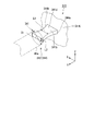
- FIG. 11 is a perspective view showing a portion of the toothbrush 310 of the present embodiment.
- the toothbrush 310 includes a toothbrush handle 314.
- the toothbrush handle 314 has a handle portion 11 and a neck portion 312.
- the neck portion 312 has a first columnar portion 341.
- the first columnar part 341 includes a main body part 41a and a handle part side hinge part 341b.
- the handle part side hinge part 341b has a plate shape.
- the handle part side hinge part 341b has a main surface 341d parallel to a surface (XY plane) including the longitudinal direction (Y-axis direction) and the lateral direction (X-axis direction).
- a main surface of a certain object includes a surface having the largest area among a plurality of surfaces of a certain object.
- concave portions 344a and 344b that are recessed in the short direction are provided at both ends in the short direction (X-axis direction).
- the concave portion 344a is recessed from one side ( ⁇ X side) in the short direction of the hinge portion 341b on the handle side to the other side (+ X side) in the short side.
- the recess 344b is recessed from the other side in the short side direction (+ X side) of the handle part side hinge 341b to one side in the short side direction ( ⁇ X side).
- the handle portion side hinge portion 341b has a dimension L1 in the short direction (X-axis direction) smaller than the diameter D1 of the main body portion 41a.
- the dimension L2 in the thickness direction (Z-axis direction) of the handle part side hinge part 341b is smaller than the diameter D1 of the main body part 41a. That is, at least a part of the handle part side hinge part 341b is smaller in dimensions in the short side direction (X-axis direction, second direction) and in the thickness direction (Z-axis direction, third direction) than the main body part 41a.
- the other structure of the handle part side hinge part 341b is the same as that of the handle part side hinge part 41b of the first embodiment.
- the first columnar portion 341 has a head portion side hinge portion.
- the head part side hinge part has a plate shape having a main surface parallel to a plane including the longitudinal direction (Y axis direction) and the short side direction (X axis direction).
- a concave portion that is recessed in the short direction is provided at both ends of the head portion side hinge portion in the short direction.
- the other structure of the head part side hinge part in the 1st columnar part 341 is the same as that of the structure of the head part side hinge part 41c of 1st Embodiment.
- the neck portion 312 has a second columnar portion and a third columnar portion.
- the second columnar portion and the third columnar portion in the neck portion 312 are the same as the first columnar portion 341 except that the positions are different.
- the positions of the second columnar portion and the third columnar portion in the neck portion 312 are the same as the positions of the second columnar portion 42 and the third columnar portion 43 in the first embodiment.
- the handle portion side hinge portion 341b is particularly easily bent in the short side direction (X-axis direction) and the thickness direction (Z-axis direction). Therefore, when the toothbrush 310 is moved and brushed as shown in FIGS. 6 and 7, the relative angle of the head portion 13 with respect to the handle portion 11 is less likely to change. Therefore, according to this embodiment, when the toothbrush 310 is moved and brushed as shown in FIGS. 6 and 7, the tooth row T can be brushed more appropriately.
- the recesses 344a and 344b may not be provided.
- the handle portion side hinge portion 341b has a plate shape whose main surface 341d is rectangular.
- the handle portion side hinge portion 341b and the main body portion 41a may be smoothly connected, or the main surface 341d and the end surface of the main body portion 41a on the handle portion 11 side ( ⁇ Y side) It may be connected via a slope inclined with respect to. According to this configuration, the connection strength between the handle portion side hinge portion 341b and the main body portion 41a can be improved. The same applies to the handle portion side hinge portion 341b and the handle portion 11.
Landscapes
- Brushes (AREA)
Abstract
本発明の歯ブラシハンドルの一つの態様は、複数の毛束が植設される植毛面を有するヘッド部を支持する歯ブラシハンドルであって、第1方向に延びるハンドル部と、ハンドル部とヘッド部とを接続するネック部と、を備え、ネック部は、ハンドル部からヘッド部まで延びる複数の柱状部を有し、複数の柱状部は、第1柱状部と、第2柱状部と、第3柱状部と、を少なくとも含み、第1柱状部と第2柱状部とは、第1方向と直交する第2方向に沿って並び、第3柱状部は、第1方向および第2方向と直交する第3方向において、第1柱状部および第2柱状部と異なる位置にあることを特徴とする。
Description
本発明は、歯ブラシハンドルおよび歯ブラシに関する。
本願は、2015年6月19日に、日本に出願された特願2015-123742号に基づき優先権を主張し、その内容をここに援用する。
本願は、2015年6月19日に、日本に出願された特願2015-123742号に基づき優先権を主張し、その内容をここに援用する。
歯ブラシを用いたブラッシングにおいては、歯ブラシのヘッド部に大きな力が加わると、ネック部が大きく撓み、ヘッド部とハンドル部との相対的な角度が大きく変化する場合がある。この場合、ヘッド部に植設された毛束を歯の目的部位に的確に当てつつブラッシングを行うことが困難である。そのため、目的部位を適切にブラッシングできない虞があった。
この問題に対して、例えば、特許文献1には、歯ブラシのにぎり(ハンドル部)の幾何学軸に対して略一定の角度で毛の作用を維持することを目的として、にぎりと頭部(ヘッド部)とをつなぐ首部(ネック部)が2つの縦ビームによって形成された歯ブラシが記載されている。
しかし、上記のような歯ブラシでは、一方向、例えば特許文献1ではヘッド部における毛が突き出る前面と垂直な方向、以外の方向においては、ネック部が変形する際に、ハンドル部に対するヘッド部の角度を一定に保持することができない。そのため、ヘッド部に加わる力の方向によっては、ネック部の変形に伴ってハンドル部に対するヘッド部の角度が大きく変化する。これにより、目的部位を適切にブラッシングできない問題がある。
したがって、目的部位の歯垢を効率的に除去できない問題がある。
したがって、目的部位の歯垢を効率的に除去できない問題がある。
本発明の一つの態様は、上記問題点に鑑みて成されたものであって、ヘッド部に加わる力の方向に関わらず、ハンドル部に対するヘッド部の角度を一定に保持しやすい歯ブラシハンドル、およびそのような歯ブラシハンドルを備えた歯ブラシを提供することを目的の一つとする。
本発明の歯ブラシハンドルの一つの態様は、複数の毛束が植設される植毛面を有するヘッド部を支持する歯ブラシハンドルであって、第1方向に延びるハンドル部と、前記ハンドル部と前記ヘッド部とを接続するネック部と、を備え、前記ネック部は、前記ハンドル部から前記ヘッド部まで延びる複数の柱状部を有し、前記複数の柱状部は、第1柱状部と、第2柱状部と、第3柱状部と、を少なくとも含み、前記第1柱状部と前記第2柱状部とは、前記第1方向と直交する第2方向に沿って並び、前記第3柱状部は、前記第1方向および前記第2方向と直交する第3方向において、前記第1柱状部および前記第2柱状部と異なる位置にあることを特徴とする。
前記柱状部は、本体部と、前記本体部と前記ハンドル部とを接続するハンドル部側ヒンジ部と、前記本体部と前記ヘッド部とを接続するヘッド部側ヒンジ部と、を有し、前記ハンドル部側ヒンジ部の少なくとも一部および前記ヘッド部側ヒンジ部の少なくとも一部は、前記第2方向の寸法および前記第3方向の寸法が、前記本体部における前記第2方向の寸法および前記第3方向の寸法よりも小さい構成としてもよい。
前記ハンドル部側ヒンジ部および前記ヘッド部側ヒンジ部における前記柱状部の延びる方向と直交する断面の形状は、円形状である構成としてもよい。
前記本体部における前記柱状部の延びる方向と直交する断面の形状は、円形状である構成としてもよい。
前記ハンドル部側ヒンジ部および前記ヘッド部側ヒンジ部は、前記第1方向および前記第2方向を含む面と平行な主面を有する板状であり、前記ハンドル部側ヒンジ部および前記ヘッド部側ヒンジ部における前記第2方向の両側の端部には、前記第2方向に窪む凹部が設けられる構成としてもよい。
前記ネック部は、前記柱状部同士を連結し前記柱状部の表面の少なくとも一部を覆う被覆部を有し、前記被覆部の硬度は、前記柱状部の硬度よりも小さい構成としてもよい。
前記被覆部は、前記柱状部の表面の全体を覆う構成としてもよい。
前記被覆部は、前記柱状部の表面の一部を覆い、前記柱状部の表面の他の一部は、外部に露出する構成としてもよい。
前記複数の柱状部は、前記ネック部の延びる方向に視た際に、所定の仮想円上に位置し、かつ、前記仮想円の周方向に沿って等間隔に設けられる構成としてもよい。
前記第3柱状部は、前記第2方向において、前記第1柱状部および前記第2柱状部と異なる位置にある構成としてもよい。
本発明の歯ブラシの一つの態様は、上記の歯ブラシハンドルと、前記歯ブラシハンドルに支持される前記ヘッド部と、を備え、前記植毛面は、前記第3方向に対して垂直であることを特徴とする。
本発明の一つの態様によれば、ヘッド部に加わる力の方向に関わらず、ハンドル部に対するヘッド部の角度を一定に保持しやすい歯ブラシハンドル、およびそのような歯ブラシハンドルを備えた歯ブラシが提供される。
以下、図面を参照しながら、本発明の実施形態に係る歯ブラシハンドルおよび歯ブラシについて説明する。なお、本発明の範囲は、以下の実施の形態に限定されず、本発明の技術的思想の範囲内で任意に変更可能である。また、以下の図面においては、各構成をわかりやすくするために、各構造における縮尺および数等を、実際の構造における縮尺および数等と異ならせる場合がある。
また、図面においては、適宜3次元直交座標系としてXYZ座標系を示す。XYZ座標系において、X軸方向(第2方向)は、図1に示す歯ブラシ10の短手方向、すなわち図1における上下方向、と平行な方向とする。Y軸方向(第1方向)は、図1に示す歯ブラシ10の長手方向、すなわち図1における左右方向、と平行な方向とする。Z軸方向(第3方向)は、X軸方向とY軸方向との両方と直交する方向とする。
なお、以下の説明においては、X軸方向を単に短手方向と呼ぶ場合があり、Y軸方向を単に長手方向と呼ぶ場合があり、Z軸方向を単に厚み方向と呼ぶ場合がある。
<第1実施形態>
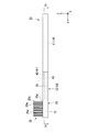
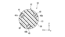
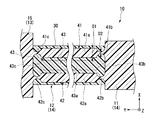
図1から図5は、本実施形態の歯ブラシ10を示す図である。図1は、平面図、すなわち、+Z側から-Z側に向かって視た図である。図2は、側面図、すなわち、X軸方向に向かって視た図である。図3は、図1におけるIII-III断面図である。図4は、図2におけるIV-IV断面図である。図5は、歯ブラシ10の部分を示す斜視図である。
図1から図5は、本実施形態の歯ブラシ10を示す図である。図1は、平面図、すなわち、+Z側から-Z側に向かって視た図である。図2は、側面図、すなわち、X軸方向に向かって視た図である。図3は、図1におけるIII-III断面図である。図4は、図2におけるIV-IV断面図である。図5は、歯ブラシ10の部分を示す斜視図である。
図1および図2に示すように、歯ブラシ10は、ヘッド部13と、歯ブラシハンドル14と、を備える。歯ブラシハンドル14は、ヘッド部13を支持するためのハンドルであり、ヘッド部13は、歯ブラシハンドル14に支持される。ヘッド部13は、ヘッド本体部15と、複数の毛束20aで構成される毛束群20と、を有する。
ヘッド本体部15は、長手方向(Y軸方向)に沿って延びる。ヘッド本体部15は、複数の毛束20aが植設される植毛面15aを有する。植毛面15aは、厚み方向(Z軸方向,第3方向)に対して垂直である。図2に示すように、複数の毛束20aは、植毛面15aから厚み方向一方側(+Z側)に延びる。
歯ブラシハンドル14は、ヘッド部13の長手方向一方側(-Y側)に接続される。歯ブラシハンドル14は、ヘッド部13を支持する。歯ブラシハンドル14は、ハンドル部11と、ネック部12と、を備える。
ハンドル部11は、歯ブラシ10における把持される部分である。ハンドル部11は、長手方向(Y軸方向,第1方向)に延びる。ネック部12は、ハンドル部11とヘッド部13とを接続する。これにより、ハンドル部11と、ネック部12と、ヘッド部13とは、長手方向に沿ってこの順に設けられる。
図1および図2に示すように、ネック部12は、複数の柱状部と、被覆部30と、を有する。複数の柱状部は、第1柱状部41と、第2柱状部42と、第3柱状部43と、を含む。本実施形態においてハンドル部11と複数の柱状部とヘッド本体部15とは、例えば、単一の部材である。
第1柱状部41、第2柱状部42および第3柱状部43は、ハンドル部11から長手方向(Y軸方向,第1方向)に延びる。第1柱状部41、第2柱状部42および第3柱状部43は、ハンドル部11からヘッド部13まで延びる。より詳細には、第1柱状部41、第2柱状部42および第3柱状部43は、ハンドル部11のヘッド部13側(+Y側)の端部から、ヘッド本体部15のハンドル部11側(-Y側)の端部まで延びる。すなわち、図1および図2に示す状態においては、第1柱状部41、第2柱状部42および第3柱状部43は、長手方向(Y軸方向)に沿って延びる。
図1および図3に示すように、第1柱状部41と第2柱状部42とは、長手方向(Y軸方向,第1方向)と直交する短手方向(X軸方向,第2方向)に沿って並ぶ。すなわち、第1柱状部41と第2柱状部42とは、厚み方向(Z軸方向)において同じ位置にある。
図2および図3に示すように、第3柱状部43は、長手方向(Y軸方向)および短手方向(X軸方向)と直交する厚み方向(Z軸方向,第3方向)において、第1柱状部41および第2柱状部42と異なる位置にある。本実施形態において第3柱状部43は、第1柱状部41および第2柱状部42よりも、厚み方向における植毛面15aと逆側(-Z側)に位置する。
図1に示すように、本実施形態において第3柱状部43は、短手方向(X軸方向,第2方向)において、第1柱状部41および第2柱状部42と異なる位置にある。本実施形態において第3柱状部43は、例えば、厚み方向(Z軸方向)に視た際に、第1柱状部41と第2柱状部42との間に位置する。本実施形態において第1柱状部41と第2柱状部42と第3柱状部43とは、厚み方向に視た際に、互いに重ならない。
図3に示すように、本実施形態において複数の柱状部、すなわち、第1柱状部41、第2柱状部42および第3柱状部43は、ネック部12の延びる方向、図3の例ではY軸方向、に視た際に、所定の仮想円C1上に位置する。第1柱状部41、第2柱状部42および第3柱状部43は、仮想円C1の周方向に沿って等間隔に設けられる。本実施形態において第3柱状部43の中心は、短手方向(X軸方向)において、例えば、仮想円C1の中心CPと同じ位置に位置する。
なお、第1柱状部41と第2柱状部42と第3柱状部43とは、配置される位置を除いて同様の構成であるため、以下の説明においては代表して第1柱状部41についてのみ説明する場合がある。
図4に示すように、第1柱状部41は、本体部41aと、ハンドル部側ヒンジ部41bと、ヘッド部側ヒンジ部41cと、を有する。図3および図4に示すように、本体部41aは、長手方向(Y軸方向)に延びる円柱状である。すなわち、図4に示すように、本体部41aにおける第1柱状部41の延びる方向(Y軸方向)と直交する断面の形状は、円形状である。
ハンドル部側ヒンジ部41bは、本体部41aとハンドル部11とを接続する。図5に示すように、本実施形態においてハンドル部側ヒンジ部41bは、円柱の中央が括れた形状である。すなわち、図4に示すように、本実施形態において、ハンドル部側ヒンジ部41bにおける第1柱状部41の延びる方向と直交する断面の形状は、円形状である。
ハンドル部側ヒンジ部41bの直径D2は、ハンドル部側ヒンジ部41bの長手方向(Y軸方向)の中央において最も小さく、長手方向の中央から長手方向両側(±Y側)に離れるに従って大きくなる。ハンドル部側ヒンジ部41bの長手方向両側の端部における直径D2は、本体部41aの直径D1と同じである。すなわち、ハンドル部側ヒンジ部41bの直径D2は、長手方向両側の端部を除いて、本体部41aの直径D1よりも小さい。
これにより、ハンドル部側ヒンジ部41bの少なくとも一部は、短手方向(X軸方向,第2方向)の寸法および厚み方向(Z軸方向,第3方向)の寸法が、本体部41aにおける短手方向の寸法および厚み方向の寸法よりも小さい。本実施形態においては、長手方向両側の端部を除くハンドル部側ヒンジ部41bの寸法は、長手方向(Y軸方向)と直交するすべての方向において、本体部41aの寸法よりも小さい。
ヘッド部側ヒンジ部41cは、本体部41aとヘッド部13とを接続する。より詳細には、ヘッド部側ヒンジ部41cは、本体部41aとヘッド本体部15とを接続する。ヘッド部側ヒンジ部41cのその他の構成は、ハンドル部側ヒンジ部41bの構成と同様である。すなわち、ヘッド部側ヒンジ部41cの少なくとも一部は、短手方向(X軸方向)の寸法および厚み方向(Z軸方向)の寸法が、本体部41aよりも小さい。ヘッド部側ヒンジ部41cにおける第1柱状部41の延びる方向と直交する断面の形状は、円形状である。
第2柱状部42は、本体部42aと、ハンドル部側ヒンジ部42bと、ヘッド部側ヒンジ部42cと、を有する。第3柱状部43は、本体部43aと、ハンドル部側ヒンジ部43bと、ヘッド部側ヒンジ部43cと、を有する。本体部42a,43aの構成は、本体部41aの構成と同様である。ハンドル部側ヒンジ部42b,43bの構成は、ハンドル部側ヒンジ部41bの構成と同様である。ヘッド部側ヒンジ部42c,43cの構成は、ヘッド部側ヒンジ部41cの構成と同様である。
第1柱状部41は、例えば、硬質樹脂製である。硬質樹脂は、例えば、ポリプロピレン(PP:Polypropylene)、ポリオキシメチレン(POM:Polyoxymethylene)、ポリブチレンテレフタレート(PBT:Polybutylene Terephthalate)、ポリエチレンテレフタレート(PET:Polyethylene Terephthalate)、ポリシクロヘキサンジメチレンテレフタレート(PCT:Polycyclohexylenedimethylene Terephthalate)、PCTの酸成分の一部をイソプロピルアルコール(IPA:Isopropyl Alcohol)で置換した樹脂(PCTA樹脂)等である。
第1柱状部41を形成する硬質樹脂は、例えば、PBTまたはPOMであることが好ましい。PBTおよびPOMは、疲労強度に優れるためである。第1柱状部41を形成する硬質樹脂の硬度は、例えば、70度以上、90度以下である。
なお、本明細書において樹脂の硬度は、JIS K 6253-3:2012に基づいて、タイプAのデュロメータで測定した場合の値である。
図1および図2に示すように、被覆部30は、ハンドル部11からヘッド部13まで延びる。より詳細には、被覆部30は、ハンドル部11のヘッド部13側(+Y側)の端部から、ヘッド本体部15のハンドル部11側(-Y側)の端部まで延びる。図1から図3に示すように、本実施形態において被覆部30は、長手方向(Y軸方向)に延びる円柱状である。
被覆部30は、柱状部同士、すなわち、第1柱状部41と第2柱状部42と第3柱状部43とを連結する。被覆部30は、第1柱状部41の表面の少なくとも一部、第2柱状部42の表面の少なくとも一部、および第3柱状部43の表面の少なくとも一部を覆う。本実施形態において被覆部30は、第1柱状部41の表面の全体、第2柱状部42の表面の全体、および第3柱状部43の表面の全体を覆う。すなわち、本実施形態において第1柱状部41の全体、第2柱状部42の全体、および第3柱状部43の全体は、被覆部30に埋設される。
図3に示すように、本実施形態において被覆部30のネック部12が延びる方向(Y軸方向)と直交する断面の形状は、例えば、円形状である。本実施形態において被覆部30の断面の中心は、仮想円C1の中心CPと一致する。
被覆部30の硬度は、第1柱状部41の硬度よりも小さい。被覆部30は、例えば、軟質樹脂製である。軟質樹脂は、例えば、熱可塑性エラストマー(TPE:Thermoplastic Elastomers)等である。被覆部30を形成する軟質樹脂の硬度は、例えば、25度以上、65度以下である。被覆部30の硬度は、例えば、使用者が好むブラッシング時の反発力に応じて決定できる。
被覆部30の体積が大きいほど、ブラッシング時の反発力は大きくなる。そのため、被覆部30の体積を、使用者が好むブラッシング時の反発力に応じて決定してもよい。
本実施形態によれば、ネック部12は、3つの柱状部、すなわち、第1柱状部41と第2柱状部42と第3柱状部43とを有する。第1柱状部41と第2柱状部42とは、短手方向に沿って並び、第3柱状部43は、厚み方向において第1柱状部41および第2柱状部42と異なる位置にある。そのため、長手方向に直交するいずれの方向においても、第1柱状部41と第2柱状部42と第3柱状部43とのうちの少なくとも2つは、異なる位置にある。言い換えると、長手方向に直交するいずれの方向においても、第1柱状部41と第2柱状部42と第3柱状部43とが同じ位置となることがない。
これにより、歯ブラシ10を長手方向に直交するいずれの方向に視た場合であっても、少なくとも2つの柱状部と、ヘッド本体部15と、ハンドル部11とによって、平行リンク機構と同様の構造が形成される。したがって、ヘッド部13に長手方向と直交するいずれの方向に力が加えられた場合であっても、ネック部12がヘッド本体部15とハンドル部11との相対的な角度を保持しつつ変形しやすい。その結果、ヘッド部13とハンドル部11との相対的な角度が変化することを抑制できる。
以上により、本実施形態によれば、ヘッド部13に加わる力の方向に関わらず、ハンドル部11に対するヘッド部13の角度を一定に保持しやすい歯ブラシハンドル14、およびそのような歯ブラシハンドル14を備えた歯ブラシ10が得られる。
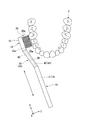
ヘッド本体部15とハンドル部11との相対的な角度変化を抑制できる効果について、図6および図7を用いてより具体的に説明する。図6および図7は、本実施形態の効果を説明するための説明図である。図6は、本実施形態における歯ブラシ10を長手方向(Y軸方向)に動かしてブラッシングする場合を示している。図7は、本実施形態における歯ブラシ10を短手方向(X軸方向)に動かしてブラッシングする場合を示している。
図6に示すように、毛束群20が歯列Tに押し付けられると、ヘッド部13に厚み方向(Z軸方向)の力が加えられる。そして、ヘッド部13に加えられた力によってネック部12が変形する。このとき、第1柱状部41あるいは第2柱状部42と、第3柱状部43と、ヘッド本体部15と、ハンドル部11と、によって平行リンク機構と同様の構造が形成される。そのため、第1柱状部41あるいは第2柱状部42と第3柱状部43とを介して接続されたヘッド本体部15とハンドル部11との相対的な角度が変化することを抑制できる。これにより、ヘッド部13の植毛面15aを、ハンドル部11を動かす方向(Y軸方向)と平行に維持しやすい。したがって、毛束群20を歯列Tに対して適切に接触させ、歯列Tを適切にブラッシングすることができる。
また、図7に示すように、歯ブラシ10を短手方向(X軸方向)に動かす場合においては、例えば、第1柱状部41と第2柱状部42と第3柱状部43とのうちのいずれか2つと、ヘッド本体部15と、ハンドル部11と、によって平行リンク機構と同様の構造が形成される。これにより、ヘッド本体部15の長手方向がハンドル部11の長手方向に対して傾くことが抑制される。したがって、ヘッド部13を歯列Tに対して短手方向(X軸方向)に平行に動かすことができ、歯列Tを適切にブラッシングすることができる。
また、本実施形態によれば、第1柱状部41は、ハンドル部側ヒンジ部41bと、ヘッド部側ヒンジ部41cとを有する。そのため、ハンドル部側ヒンジ部41bとヘッド部側ヒンジ部41cとが屈曲することで、第1柱状部41が、より平行リンク機構を構成するリンクと同様に動作しやすい。すなわち、ネック部12の角度が変化した場合であっても、ヘッド部13とハンドル部11との相対的な角度をより保持しやすい。
図6および図7に示すようなブラッシング、すなわち歯ブラシ10を長手方向(Y軸方向)に動かすブラッシングおよび歯ブラシ10を短手方向(X軸方向)に動かすブラッシングは、特に行われやすい。そのため、図6および図7に示すようなブラッシングを行う際に、ヘッド部13とハンドル部11との相対的な角度が変化しないことが、特に求められる。
これに対して、本実施形態によれば、ハンドル部側ヒンジ部41bの少なくとも一部およびヘッド部側ヒンジ部41cの少なくとも一部は、短手方向(X軸方向)の寸法および厚み方向(Z軸方向)の寸法が、本体部41aにおける短手方向の寸法および厚み方向の寸法よりも小さい。そのため、ハンドル部側ヒンジ部41bおよびヘッド部側ヒンジ部41cは、短手方向および厚み方向に屈曲しやすい。ハンドル部側ヒンジ部42b,43bおよびヘッド部側ヒンジ部42c,43cについても同様である。
これにより、歯ブラシ10を長手方向および短手方向に動かすブラッシングにおいて、ヘッド部13とネック部12とハンドル部11とが、より平行リンク機構と同様に動作しやすい。したがって、本実施形態によれば、図6および図7に示すようなブラッシングを行う際に、ヘッド部13とハンドル部11との相対的な角度が変化することをより抑制できる。
また、本実施形態によれば、ハンドル部側ヒンジ部41bおよびヘッド部側ヒンジ部41cにおける第1柱状部41が延びる方向と直交する断面の形状は、円形状である。そのため、ハンドル部側ヒンジ部41bおよびヘッド部側ヒンジ部41cは、第1柱状部41が延びる方向と直交するいずれの方向においても屈曲しやすい。第2柱状部42および第3柱状部43についても同様である。これにより、ヘッド部13に長手方向(Y軸方向)と直交するいずれの方向の力が加えられた場合であっても、ヘッド本体部15とネック部12とハンドル部11とが、より平行リンク機構と同様に動作しやすい。
また、本実施形態によれば、第1柱状部41と第2柱状部42と第3柱状部43とは、被覆部30によって連結されるため、ネック部12の強度を確保しやすい。また、被覆部30は、第1柱状部41よりも硬度が小さい。そのため、第1柱状部41のハンドル部側ヒンジ部41bおよびヘッド部側ヒンジ部41cが変形することを阻害しにくい。
また、本実施形態によれば、被覆部30は、第1柱状部41の表面の全体を覆う。そのため、第1柱状部41が破損した場合であっても、第1柱状部41の一部が脱落することを抑制できる。
また、本実施形態によれば、第1柱状部41と第2柱状部42と第3柱状部43とは、ネック部12の延びる方向に視た際に、仮想円C1上に位置し、かつ、仮想円C1の周方向に沿って等間隔に設けられる。そのため、長手方向(Y軸方向)と直交するいずれの方向においても、各柱状部とヘッド本体部15とハンドル部11とによる平行リンク機構と同様の構造が安定して形成されやすい。また、ネック部12の強度を、長手方向と直交する方向のいずれにおいても均等に向上させやすい。
また、本実施形態によれば、第3柱状部43は、短手方向(X軸方向)において、第1柱状部41および第2柱状部42と異なる位置にある。そのため、図8に示すような金型50を用いて各柱状部を成形できる。図8は、歯ブラシ10を製造するための金型50を示す図である。
図8に示すように、金型50は、第1金型51と、第2金型52と、を有する。第1金型51は、第1成形凹部51aと、第2成形凹部51bと、第3成形凹部51cと、を有する。第1成形凹部51a、第2成形凹部51b、および第3成形凹部51cは、厚み方向一方側(+Z側)に窪む。
第2金型52は、第1成形凹部52aと、第2成形凹部52bと、第3成形凹部52cと、を有する。第1成形凹部52a、第2成形凹部52b、および第3成形凹部52cは、厚み方向他方側(-Z側)に窪む。
第1金型51と第2金型52とが厚み方向(Z軸方向)に組み合わされることで、第1成形空間53と、第2成形空間54と、第3成形空間55と、が形成される。第1成形空間53は、第1成形凹部51aと第1成形凹部52aとによって形成される。第2成形空間54は、第2成形凹部51bと第2成形凹部52bとによって形成される。第3成形空間55は、第3成形凹部51cと第3成形凹部52cとによって形成される。
第1成形空間53に樹脂が流し込まれることによって、第1柱状部41が成形される。第2成形空間54に樹脂が流し込まれることによって、第2柱状部42が成形される。第3成形空間55に樹脂が流し込まれることによって、第3柱状部43が成形される。
以上のように、本実施形態によれば、第1柱状部41と第2柱状部42と第3柱状部43とが、短手方向(X軸方向)において、互いに異なる位置にあるため、2つの部品、すなわち第1金型51および第2金型52からなる金型50を用いて一度に3つの柱状部を成形することができる。したがって、本実施形態によれば、ネック部12を成形する金型の構成を簡単にでき、複数の柱状部を容易に成形できる。その結果、歯ブラシ10の製造に要する手間およびコストを低減できる。
なお、本実施形態においては、以下の構成を採用することもできる。以下の説明においては、上記説明と同様の構成については、適宜同一の符号を付す等により説明を省略する場合がある。
本実施形態において第1柱状部41の延びる方向と、第2柱状部42の延びる方向と、第3柱状部43の延びる方向とは、厳密に平行でなくてもよい。本実施形態において各柱状部の延びる方向は、例えば、互いに平行な方向から10°以下の範囲内で、互いに傾いてもよい。
また、本実施形態において第1柱状部41と第2柱状部42と第3柱状部43とは、仮想円C1上において、周方向に等間隔に位置しなくてもよい。また、本実施形態において第1柱状部41と第2柱状部42と第3柱状部43とは、仮想円C1上に位置しなくてもよい。
また、上記説明においては、第1柱状部41と第2柱状部42とが並ぶ方向(第2方向)は、歯ブラシ10の短手方向と平行な方向としたが、これに限られない。本実施形態において第1柱状部41と第2柱状部42とが並ぶ方向は、長手方向と直交するいずれの方向であってもよい。これに伴って、第1柱状部41と第2柱状部42とが並ぶ方向および歯ブラシ10の長手方向と直交する方向(第3方向)は、植毛面15aと垂直な方向でなくてもよい。
また、本実施形態においては、図9に示すような構成を採用してもよい。図9は、本実施形態の他の一例である歯ブラシ110を示す断面図である。図9に示すように、歯ブラシ110は、歯ブラシハンドル114を備える。歯ブラシハンドル114は、ネック部112を有する。ネック部112は、第1柱状部41と、第2柱状部42と、第3柱状部43と、被覆部130と、を有する。
被覆部130は、第1柱状部41の表面の一部と、第2柱状部42の表面の一部と、第3柱状部43の表面の一部と、を覆う。被覆部130の直径は、図3等に示す被覆部30の直径よりも小さい。被覆部130のその他の構成は、図3等に示す被覆部30の構成と同様である。第1柱状部41の表面の他の一部、第2柱状部42の表面の他の一部、および第3柱状部43の表面の他の一部は、外部に露出する。各柱状部の表面の他の一部とは、各柱状部の表面のうち被覆部130によって覆われた部分以外の部分全体、あるいは各柱状部の表面のうち被覆部130によって覆われた部分以外の部分の一部である。本実施形態では、各柱状部の表面のうち被覆部130によって覆われた部分以外の部分全体が露出する。
この構成によれば、被覆部130の直径を小さくできるため、ネック部112を細くしやすい。また、被覆部130を形成する材料の量を少なくできるため、歯ブラシ110の製造コストを低減できる。
また、本実施形態において柱状部の数は、柱状部が第1柱状部と第2柱状部と第3柱状部とを少なくとも含む範囲内において、特に限定されず、例えば図10に示す構成のように、4つ以上であってもよい。柱状部の数が大きいほど、長手方向(Y軸方向)と直交するいずれの方向においても、安定して平行リンクと同様の構造が安定して形成されやすい。
図10は、本実施形態の他の一例である歯ブラシ210を示す断面図である。図10に示すように、歯ブラシ210は、歯ブラシハンドル214を備える。歯ブラシハンドル214は、ネック部212を有する。ネック部212は、5つの柱状部241,242,243,244,245と、被覆部30と、を有する。
5つの柱状部241~245は、Y軸方向に視た際に、所定の仮想円C2上に位置する。柱状部241~245は、仮想円C2の周方向に沿って等間隔に設けられる。この構成においては、柱状部241~245のうちのいずれか2つを第1柱状部および第2柱状部としたとき、柱状部241~245のうちのその他の3つが第3柱状部に相当する。
また、本実施形態においてハンドル部側ヒンジ部41bおよびヘッド部側ヒンジ部41cにおける第1柱状部41の延びる方向と直交する断面の形状は、特に限定されず、多角形状であってもよいし、楕円形状であってもよい。また、本実施形態においてハンドル部側ヒンジ部41bおよびヘッド部側ヒンジ部41cは設けられなくてもよい。
また、本実施形態においてハンドル部側ヒンジ部41bの全体およびヘッド部側ヒンジ部41cの全体は、短手方向の寸法および厚み方向の寸法が、本体部41aよりも小さい構成としてもよい。
また、本実施形態態においてハンドル部側ヒンジ部41bの少なくとも一部およびヘッド部側ヒンジ部41cの少なくとも一部は、短手方向の寸法と厚み方向の寸法とのうちのいずれか一方のみが、本体部41aよりも小さくてもよい。
また、本実施形態においては、ハンドル部側ヒンジ部41bおよびヘッド部側ヒンジ部41cが設けられなくてもよい。
また、本実施形態において被覆部30は、設けられなくてもよい。
また、本実施形態においてヘッド本体部15は、歯ブラシハンドル14と別部材であってもよい。また、本実施形態において複数の柱状部とハンドル部11とは、別部材であってもよい。
<第2実施形態>
第2実施形態は、第1実施形態に対して、ヒンジ部の形状が異なる。なお、以下の説明においては、上記実施形態と同様の構成については、適宜同一の符号を付す等により説明を省略する場合がある。
第2実施形態は、第1実施形態に対して、ヒンジ部の形状が異なる。なお、以下の説明においては、上記実施形態と同様の構成については、適宜同一の符号を付す等により説明を省略する場合がある。
図11は、本実施形態の歯ブラシ310の部分を示す斜視図である。図11に示すように、歯ブラシ310は、歯ブラシハンドル314を備える。歯ブラシハンドル314は、ハンドル部11と、ネック部312と、を有する。ネック部312は、第1柱状部341を有する。第1柱状部341は、本体部41aと、ハンドル部側ヒンジ部341bと、を有する。
ハンドル部側ヒンジ部341bは、板状である。ハンドル部側ヒンジ部341bは、長手方向(Y軸方向)および短手方向(X軸方向)を含む面(XY平面)と平行な主面341dを有する。
なお、本明細書において、ある対象の主面、とは、ある対象が有する複数の面のうちで、最も面積が大きい面を含む。
ハンドル部側ヒンジ部341bにおける短手方向(X軸方向)の両側の端部には、短手方向に窪む凹部344a,344bが設けられる。凹部344aは、ハンドル部側ヒンジ部341bの短手方向一方側(-X側)から短手方向他方側(+X側)に窪む。凹部344bは、ハンドル部側ヒンジ部341bの短手方向他方側(+X側)から短手方向一方側(-X側)に窪む。
凹部344a,344bが設けられる位置において、ハンドル部側ヒンジ部341bの短手方向(X軸方向)の寸法L1は、本体部41aの直径D1よりも小さい。ハンドル部側ヒンジ部341bの厚み方向(Z軸方向)の寸法L2は、本体部41aの直径D1よりも小さい。すなわち、ハンドル部側ヒンジ部341bの少なくとも一部は、短手方向(X軸方向,第2方向)の寸法および厚み方向(Z軸方向,第3方向)の寸法が、本体部41aよりも小さい。ハンドル部側ヒンジ部341bのその他の構成は、第1実施形態のハンドル部側ヒンジ部41bの構成と同様である。
図示は省略するが、第1柱状部341は、ヘッド部側ヒンジ部を有する。ヘッド部側ヒンジ部は、ハンドル部側ヒンジ部341bと同様に、長手方向(Y軸方向)および短手方向(X軸方向)を含む面と平行な主面を有する板状である。ヘッド部側ヒンジ部における短手方向の両側の端部には、短手方向に窪む凹部が設けられる。第1柱状部341におけるヘッド部側ヒンジ部のその他の構成は、第1実施形態のヘッド部側ヒンジ部41cの構成と同様である。
図示は省略するが、ネック部312は、第2柱状部と、第3柱状部と、を有する。ネック部312における第2柱状部および第3柱状部は、位置が異なる点を除いて、第1柱状部341と同様である。ネック部312における第2柱状部および第3柱状部の位置は、第1実施形態における第2柱状部42および第3柱状部43の位置と同様である。
本実施形態によれば、ハンドル部側ヒンジ部341bは、短手方向(X軸方向)および厚み方向(Z軸方向)において、特に屈曲しやすい。そのため、図6および図7に示すように歯ブラシ310を動かしてブラッシングする際に、ハンドル部11に対するヘッド部13の相対角度がより変化しにくい。したがって、本実施形態によれば、図6および図7に示すように歯ブラシ310を動かしてブラッシングする際に、歯列Tをより適切にブラッシングできる。
なお、本実施形態においては、以下の構成を採用することもできる。
本実施形態においては、凹部344a,344bは設けられなくてもよい。この場合、ハンドル部側ヒンジ部341bは、主面341dが矩形状の板状である。
また、本実施形態においては、ハンドル部側ヒンジ部341bと本体部41aとは、滑らかに接続されてもよいし、主面341dと本体部41aのハンドル部11側(-Y側)の端面とに対して傾く斜面を介して接続されてもよい。この構成によれば、ハンドル部側ヒンジ部341bと本体部41aとの接続強度を向上できる。ハンドル部側ヒンジ部341bとハンドル部11とについても同様である。
なお、上記説明した第1実施形態および第2実施形態の各構成は、相互に矛盾しない範囲内において、適宜組み合わせることができる。
10,110,210,310…歯ブラシ、11…ハンドル部、12,112,212,312…ネック部、13…ヘッド部、14,114,214,314…歯ブラシハンドル、15a…植毛面、20a…毛束、30,130…被覆部、41,341…第1柱状部(柱状部)、41a,42a,43a…本体部、41b,42b,43b,341b…ハンドル部側ヒンジ部、41c,42c,43c…ヘッド部側ヒンジ部、42…第2柱状部(柱状部)、43…第3柱状部(柱状部)、241,242,243,244,245…柱状部、341d…主面、344a,344b…凹部、C1,C2…仮想円
Claims (11)
- 複数の毛束が植設される植毛面を有するヘッド部を支持する歯ブラシハンドルであって、
第1方向に延びるハンドル部と、
前記ハンドル部と前記ヘッド部とを接続するネック部と、
を備え、
前記ネック部は、前記ハンドル部から前記ヘッド部まで延びる複数の柱状部を有し、
前記複数の柱状部は、第1柱状部と、第2柱状部と、第3柱状部と、を少なくとも含み、
前記第1柱状部と前記第2柱状部とは、前記第1方向と直交する第2方向に沿って並び、
前記第3柱状部は、前記第1方向および前記第2方向と直交する第3方向において、前記第1柱状部および前記第2柱状部と異なる位置にあることを特徴とする歯ブラシハンドル。 - 前記柱状部は、本体部と、前記本体部と前記ハンドル部とを接続するハンドル部側ヒンジ部と、前記本体部と前記ヘッド部とを接続するヘッド部側ヒンジ部と、を有し、
前記ハンドル部側ヒンジ部の少なくとも一部および前記ヘッド部側ヒンジ部の少なくとも一部は、前記第2方向の寸法および前記第3方向の寸法が、前記本体部における前記第2方向の寸法および前記第3方向の寸法よりも小さい、請求項1に記載の歯ブラシハンドル。 - 前記ハンドル部側ヒンジ部および前記ヘッド部側ヒンジ部における前記柱状部の延びる方向と直交する断面の形状は、円形状である、請求項2に記載の歯ブラシハンドル。
- 前記本体部における前記柱状部の延びる方向と直交する断面の形状は、円形状である、請求項3に記載の歯ブラシハンドル。
- 前記ハンドル部側ヒンジ部および前記ヘッド部側ヒンジ部は、前記第1方向および前記第2方向を含む面と平行な主面を有する板状であり、
前記ハンドル部側ヒンジ部および前記ヘッド部側ヒンジ部における前記第2方向の両側の端部には、前記第2方向に窪む凹部が設けられる、請求項2に記載の歯ブラシハンドル。 - 前記ネック部は、前記柱状部同士を連結し前記柱状部の表面の少なくとも一部を覆う被覆部を有し、
前記被覆部の硬度は、前記柱状部の硬度よりも小さい、請求項1から5のいずれか一項に記載の歯ブラシハンドル。 - 前記被覆部は、前記柱状部の表面の全体を覆う、請求項6に記載の歯ブラシハンドル。
- 前記被覆部は、前記柱状部の表面の一部を覆い、
前記柱状部の表面の他の一部は、外部に露出する、請求項6に記載の歯ブラシハンドル。 - 前記複数の柱状部は、前記ネック部の延びる方向に視た際に、所定の仮想円上に位置し、かつ、前記仮想円の周方向に沿って等間隔に設けられる、請求項1から8のいずれか一項に記載の歯ブラシハンドル。
- 前記第3柱状部は、前記第2方向において、前記第1柱状部および前記第2柱状部と異なる位置にある、請求項1から9のいずれか一項に記載の歯ブラシハンドル。
- 請求項1から10のいずれか一項に記載の歯ブラシハンドルと、
前記歯ブラシハンドルに支持される前記ヘッド部と、
を備え、
前記植毛面は、前記第3方向に対して垂直であることを特徴とする歯ブラシ。
Priority Applications (2)
| Application Number | Priority Date | Filing Date | Title |
|---|---|---|---|
| CN201680036004.2A CN107708479A (zh) | 2015-06-19 | 2016-06-16 | 牙刷柄以及牙刷 |
| KR1020177023223A KR20180020944A (ko) | 2015-06-19 | 2016-06-16 | 칫솔 핸들 및 칫솔 |
Applications Claiming Priority (2)
| Application Number | Priority Date | Filing Date | Title |
|---|---|---|---|
| JP2015123742A JP6552091B2 (ja) | 2015-06-19 | 2015-06-19 | 歯ブラシハンドルおよび歯ブラシ |
| JP2015-123742 | 2015-06-19 |
Publications (1)
| Publication Number | Publication Date |
|---|---|
| WO2016204224A1 true WO2016204224A1 (ja) | 2016-12-22 |
Family
ID=57545261
Family Applications (1)
| Application Number | Title | Priority Date | Filing Date |
|---|---|---|---|
| PCT/JP2016/067930 Ceased WO2016204224A1 (ja) | 2015-06-19 | 2016-06-16 | 歯ブラシハンドルおよび歯ブラシ |
Country Status (4)
| Country | Link |
|---|---|
| JP (1) | JP6552091B2 (ja) |
| KR (1) | KR20180020944A (ja) |
| CN (1) | CN107708479A (ja) |
| WO (1) | WO2016204224A1 (ja) |
Cited By (4)
| Publication number | Priority date | Publication date | Assignee | Title |
|---|---|---|---|---|
| US20220047064A1 (en) * | 2018-12-27 | 2022-02-17 | Lion Corporation | Toothbrush |
| TWI766856B (zh) * | 2016-03-09 | 2022-06-11 | 日商獅子股份有限公司 | 牙刷 |
| USD1056514S1 (en) | 2022-11-22 | 2025-01-07 | Kao Usa Inc. | Handle for brush head |
| US12465137B2 (en) | 2022-11-22 | 2025-11-11 | Kao Usa Inc. | Handle for brush head |
Citations (2)
| Publication number | Priority date | Publication date | Assignee | Title |
|---|---|---|---|---|
| JPH08332116A (ja) * | 1995-02-01 | 1996-12-17 | Johnson & Johnson Consumer Prod Inc | 歯ブラシ |
| US5987690A (en) * | 1995-05-30 | 1999-11-23 | Heuler; Uwe | Resilient toothbrush |
Family Cites Families (3)
| Publication number | Priority date | Publication date | Assignee | Title |
|---|---|---|---|---|
| CN201831194U (zh) * | 2010-09-29 | 2011-05-18 | 徐秋萍 | 一种注塑刷毛牙刷 |
| KR101548839B1 (ko) * | 2010-12-21 | 2015-08-31 | 콜게이트-파아므올리브캄파니 | 구강 관리 기구 |
| JP5830277B2 (ja) * | 2011-06-20 | 2015-12-09 | ライオン株式会社 | 歯ブラシ |
-
2015
- 2015-06-19 JP JP2015123742A patent/JP6552091B2/ja not_active Expired - Fee Related
-
2016
- 2016-06-16 CN CN201680036004.2A patent/CN107708479A/zh active Pending
- 2016-06-16 WO PCT/JP2016/067930 patent/WO2016204224A1/ja not_active Ceased
- 2016-06-16 KR KR1020177023223A patent/KR20180020944A/ko not_active Withdrawn
Patent Citations (2)
| Publication number | Priority date | Publication date | Assignee | Title |
|---|---|---|---|---|
| JPH08332116A (ja) * | 1995-02-01 | 1996-12-17 | Johnson & Johnson Consumer Prod Inc | 歯ブラシ |
| US5987690A (en) * | 1995-05-30 | 1999-11-23 | Heuler; Uwe | Resilient toothbrush |
Cited By (5)
| Publication number | Priority date | Publication date | Assignee | Title |
|---|---|---|---|---|
| TWI766856B (zh) * | 2016-03-09 | 2022-06-11 | 日商獅子股份有限公司 | 牙刷 |
| US20220047064A1 (en) * | 2018-12-27 | 2022-02-17 | Lion Corporation | Toothbrush |
| US12144415B2 (en) * | 2018-12-27 | 2024-11-19 | Lion Corporation | Toothbrush |
| USD1056514S1 (en) | 2022-11-22 | 2025-01-07 | Kao Usa Inc. | Handle for brush head |
| US12465137B2 (en) | 2022-11-22 | 2025-11-11 | Kao Usa Inc. | Handle for brush head |
Also Published As
| Publication number | Publication date |
|---|---|
| CN107708479A (zh) | 2018-02-16 |
| JP2017006304A (ja) | 2017-01-12 |
| KR20180020944A (ko) | 2018-02-28 |
| JP6552091B2 (ja) | 2019-07-31 |
Similar Documents
| Publication | Publication Date | Title |
|---|---|---|
| WO2016204224A1 (ja) | 歯ブラシハンドルおよび歯ブラシ | |
| JP6409825B2 (ja) | 歯間清掃具の製造方法 | |
| JP7069377B2 (ja) | 歯ブラシ | |
| JP7001480B2 (ja) | 流体状またはペースト状の製品をケラチン繊維に塗布する塗布用具 | |
| JP2007044524A (ja) | 化粧物質を塗布するためのブラシ | |
| US20190125506A1 (en) | Interdental cleaner | |
| CN108024619B (zh) | 牙刷 | |
| CN102525089A (zh) | 涂抹器装置、涂抹器以及涂抹器套件 | |
| CN109890248B (zh) | 牙刷和牙刷制造方法 | |
| JP2017042493A (ja) | 基部、歯間清掃具及び歯間清掃具の製造方法 | |
| KR102255086B1 (ko) | 속눈썹 및/또는 눈썹에 코스메틱, 메이크업 또는 케어 제품을 도포하기 위한 어플리케이터 | |
| WO2018079115A1 (ja) | 歯ブラシ | |
| WO2016194819A1 (ja) | 頭皮洗浄用ブラシ | |
| JP6858123B2 (ja) | 歯ブラシ | |
| JP6351167B2 (ja) | マスカラ用アプリケータ | |
| JP7511402B2 (ja) | 歯間清掃具 | |
| JP2022011651A (ja) | 歯間清掃具 | |
| JP2018023432A (ja) | 歯ブラシ | |
| CN110049696B (zh) | 用于化妆品的涂敷器以及相关的涂敷器组件 | |
| JP6869634B2 (ja) | 歯ブラシ | |
| CN113939211B (zh) | 牙刷 | |
| JP2016022157A (ja) | マスカラ用アプリケータ | |
| JP2014036752A (ja) | 清掃具 | |
| AU2004270032A1 (en) | Brush such as mascara | |
| JP2018064751A (ja) | 櫛ブラシ |
Legal Events
| Date | Code | Title | Description |
|---|---|---|---|
| 121 | Ep: the epo has been informed by wipo that ep was designated in this application |
Ref document number: 16811698 Country of ref document: EP Kind code of ref document: A1 |
|
| ENP | Entry into the national phase |
Ref document number: 20177023223 Country of ref document: KR Kind code of ref document: A |
|
| NENP | Non-entry into the national phase |
Ref country code: DE |
|
| 122 | Ep: pct application non-entry in european phase |
Ref document number: 16811698 Country of ref document: EP Kind code of ref document: A1 |