WO2016204157A1 - Valve seat machining device, and valve seat machining method using said valve seat machining device - Google Patents
Valve seat machining device, and valve seat machining method using said valve seat machining device Download PDFInfo
- Publication number
- WO2016204157A1 WO2016204157A1 PCT/JP2016/067722 JP2016067722W WO2016204157A1 WO 2016204157 A1 WO2016204157 A1 WO 2016204157A1 JP 2016067722 W JP2016067722 W JP 2016067722W WO 2016204157 A1 WO2016204157 A1 WO 2016204157A1
- Authority
- WO
- WIPO (PCT)
- Prior art keywords
- valve
- valve seat
- main body
- processing machine
- body part
- Prior art date
Links
Images


Classifications
-
- B—PERFORMING OPERATIONS; TRANSPORTING
- B23—MACHINE TOOLS; METAL-WORKING NOT OTHERWISE PROVIDED FOR
- B23C—MILLING
- B23C3/00—Milling particular work; Special milling operations; Machines therefor
- B23C3/02—Milling surfaces of revolution
- B23C3/05—Finishing valves or valve seats
-
- B—PERFORMING OPERATIONS; TRANSPORTING
- B24—GRINDING; POLISHING
- B24B—MACHINES, DEVICES, OR PROCESSES FOR GRINDING OR POLISHING; DRESSING OR CONDITIONING OF ABRADING SURFACES; FEEDING OF GRINDING, POLISHING, OR LAPPING AGENTS
- B24B15/00—Machines or devices designed for grinding seat surfaces; Accessories therefor
- B24B15/04—Machines or devices designed for grinding seat surfaces; Accessories therefor on valve members
-
- B—PERFORMING OPERATIONS; TRANSPORTING
- B23—MACHINE TOOLS; METAL-WORKING NOT OTHERWISE PROVIDED FOR
- B23B—TURNING; BORING
- B23B41/00—Boring or drilling machines or devices specially adapted for particular work; Accessories specially adapted therefor
- B23B41/12—Boring or drilling machines or devices specially adapted for particular work; Accessories specially adapted therefor for forming working surfaces of cylinders, of bearings, e.g. in heads of driving rods, or of other engine parts
-
- B—PERFORMING OPERATIONS; TRANSPORTING
- B23—MACHINE TOOLS; METAL-WORKING NOT OTHERWISE PROVIDED FOR
- B23C—MILLING
- B23C1/00—Milling machines not designed for particular work or special operations
- B23C1/20—Portable devices or machines; Hand-driven devices or machines
-
- B—PERFORMING OPERATIONS; TRANSPORTING
- B23—MACHINE TOOLS; METAL-WORKING NOT OTHERWISE PROVIDED FOR
- B23C—MILLING
- B23C3/00—Milling particular work; Special milling operations; Machines therefor
- B23C3/02—Milling surfaces of revolution
- B23C3/05—Finishing valves or valve seats
- B23C3/051—Reconditioning of valve seats
- B23C3/053—Reconditioning of valve seats having means for guiding the tool carrying spindle
- B23C3/056—Reconditioning of valve seats having means for guiding the tool carrying spindle for taps or valves
-
- B—PERFORMING OPERATIONS; TRANSPORTING
- B23—MACHINE TOOLS; METAL-WORKING NOT OTHERWISE PROVIDED FOR
- B23C—MILLING
- B23C9/00—Details or accessories so far as specially adapted to milling machines or cutter
-
- F—MECHANICAL ENGINEERING; LIGHTING; HEATING; WEAPONS; BLASTING
- F01—MACHINES OR ENGINES IN GENERAL; ENGINE PLANTS IN GENERAL; STEAM ENGINES
- F01D—NON-POSITIVE DISPLACEMENT MACHINES OR ENGINES, e.g. STEAM TURBINES
- F01D17/00—Regulating or controlling by varying flow
- F01D17/10—Final actuators
- F01D17/12—Final actuators arranged in stator parts
- F01D17/14—Final actuators arranged in stator parts varying effective cross-sectional area of nozzles or guide conduits
- F01D17/141—Final actuators arranged in stator parts varying effective cross-sectional area of nozzles or guide conduits by means of shiftable members or valves obturating part of the flow path
- F01D17/145—Final actuators arranged in stator parts varying effective cross-sectional area of nozzles or guide conduits by means of shiftable members or valves obturating part of the flow path by means of valves, e.g. for steam turbines
-
- F—MECHANICAL ENGINEERING; LIGHTING; HEATING; WEAPONS; BLASTING
- F16—ENGINEERING ELEMENTS AND UNITS; GENERAL MEASURES FOR PRODUCING AND MAINTAINING EFFECTIVE FUNCTIONING OF MACHINES OR INSTALLATIONS; THERMAL INSULATION IN GENERAL
- F16K—VALVES; TAPS; COCKS; ACTUATING-FLOATS; DEVICES FOR VENTING OR AERATING
- F16K1/00—Lift valves or globe valves, i.e. cut-off apparatus with closure members having at least a component of their opening and closing motion perpendicular to the closing faces
- F16K1/32—Details
- F16K1/34—Cutting-off parts, e.g. valve members, seats
- F16K1/42—Valve seats
-
- B—PERFORMING OPERATIONS; TRANSPORTING
- B23—MACHINE TOOLS; METAL-WORKING NOT OTHERWISE PROVIDED FOR
- B23B—TURNING; BORING
- B23B2247/00—Details of drilling jigs
- B23B2247/12—Drilling jigs with means to affix the jig to the workpiece
-
- B—PERFORMING OPERATIONS; TRANSPORTING
- B23—MACHINE TOOLS; METAL-WORKING NOT OTHERWISE PROVIDED FOR
- B23C—MILLING
- B23C2270/00—Details of milling machines, milling processes or milling tools not otherwise provided for
- B23C2270/18—Milling internal areas of components
-
- B—PERFORMING OPERATIONS; TRANSPORTING
- B23—MACHINE TOOLS; METAL-WORKING NOT OTHERWISE PROVIDED FOR
- B23Q—DETAILS, COMPONENTS, OR ACCESSORIES FOR MACHINE TOOLS, e.g. ARRANGEMENTS FOR COPYING OR CONTROLLING; MACHINE TOOLS IN GENERAL CHARACTERISED BY THE CONSTRUCTION OF PARTICULAR DETAILS OR COMPONENTS; COMBINATIONS OR ASSOCIATIONS OF METAL-WORKING MACHINES, NOT DIRECTED TO A PARTICULAR RESULT
- B23Q2709/00—Portable machines or devices for the cylindrical bores of valve bodies
-
- B—PERFORMING OPERATIONS; TRANSPORTING
- B23—MACHINE TOOLS; METAL-WORKING NOT OTHERWISE PROVIDED FOR
- B23Q—DETAILS, COMPONENTS, OR ACCESSORIES FOR MACHINE TOOLS, e.g. ARRANGEMENTS FOR COPYING OR CONTROLLING; MACHINE TOOLS IN GENERAL CHARACTERISED BY THE CONSTRUCTION OF PARTICULAR DETAILS OR COMPONENTS; COMBINATIONS OR ASSOCIATIONS OF METAL-WORKING MACHINES, NOT DIRECTED TO A PARTICULAR RESULT
- B23Q9/00—Arrangements for supporting or guiding portable metal-working machines or apparatus
- B23Q9/0007—Portable machines comprising means for their guidance or support directly on the workpiece
-
- B—PERFORMING OPERATIONS; TRANSPORTING
- B24—GRINDING; POLISHING
- B24B—MACHINES, DEVICES, OR PROCESSES FOR GRINDING OR POLISHING; DRESSING OR CONDITIONING OF ABRADING SURFACES; FEEDING OF GRINDING, POLISHING, OR LAPPING AGENTS
- B24B15/00—Machines or devices designed for grinding seat surfaces; Accessories therefor
- B24B15/02—Machines or devices designed for grinding seat surfaces; Accessories therefor in valve housings
- B24B15/03—Machines or devices designed for grinding seat surfaces; Accessories therefor in valve housings using portable or mobile machines
-
- F—MECHANICAL ENGINEERING; LIGHTING; HEATING; WEAPONS; BLASTING
- F05—INDEXING SCHEMES RELATING TO ENGINES OR PUMPS IN VARIOUS SUBCLASSES OF CLASSES F01-F04
- F05D—INDEXING SCHEME FOR ASPECTS RELATING TO NON-POSITIVE-DISPLACEMENT MACHINES OR ENGINES, GAS-TURBINES OR JET-PROPULSION PLANTS
- F05D2220/00—Application
- F05D2220/30—Application in turbines
- F05D2220/31—Application in turbines in steam turbines
-
- F—MECHANICAL ENGINEERING; LIGHTING; HEATING; WEAPONS; BLASTING
- F05—INDEXING SCHEMES RELATING TO ENGINES OR PUMPS IN VARIOUS SUBCLASSES OF CLASSES F01-F04
- F05D—INDEXING SCHEME FOR ASPECTS RELATING TO NON-POSITIVE-DISPLACEMENT MACHINES OR ENGINES, GAS-TURBINES OR JET-PROPULSION PLANTS
- F05D2230/00—Manufacture
- F05D2230/10—Manufacture by removing material
-
- F—MECHANICAL ENGINEERING; LIGHTING; HEATING; WEAPONS; BLASTING
- F05—INDEXING SCHEMES RELATING TO ENGINES OR PUMPS IN VARIOUS SUBCLASSES OF CLASSES F01-F04
- F05D—INDEXING SCHEME FOR ASPECTS RELATING TO NON-POSITIVE-DISPLACEMENT MACHINES OR ENGINES, GAS-TURBINES OR JET-PROPULSION PLANTS
- F05D2230/00—Manufacture
- F05D2230/80—Repairing, retrofitting or upgrading methods
Definitions
- the present invention relates to a valve seat processing machine for repairing a valve seat when the valve seat in a valve device used for supplying fluid to a turbine is eroded by erosion, and a valve using the valve seat processing machine
- the present invention relates to a seat processing method.
- valve device For example, in a power generation facility using a steam turbine, heat energy of steam generated in a boiler is converted into mechanical work by the steam turbine, and a valve device is provided between the boiler and the steam turbine. .
- the valve device forms a flow path for steam (fluid) sent from the boiler to the steam turbine, and opens and closes the flow path by operating the valve body and closely contacting a part of the inner wall (valve seat) in the flow path.
- valve seat when erosion occurs in the valve seat, it is necessary to repair the valve seat.
- the surface of the valve seat is cut to remove the eroded portion and is reprocessed into a shape corresponding to the valve body.
- the repair of the valve seat is performed by moving the valve device from a factory with a power generation facility (power generation factory) to a factory with a processing facility (processing factory).
- the valve device is removed from between the boiler and the steam turbine, transported from the power plant to the processing plant, repaired at the processing plant, and then the repaired valve device is transferred from the processing plant to the power plant. And then installed again between the boiler and the steam turbine.
- repair work of the valve seat in the valve device requires removal and installation work of the valve device, transportation work between factories, and processing work by the processing equipment, which requires a great deal of cost and time.
- the present invention has been made in view of the above problems, and an object thereof is to easily repair a valve seat in a valve device used for supplying fluid to a turbine.
- a valve seat processing machine for solving the above-mentioned problems is a valve main body part that forms a fluid flow path, and a valve body part that is detachably provided on the valve main body part and is in close contact with the valve seat in the valve main body part.
- a valve seat processing machine that processes the valve seat in a valve device that includes a valve drive unit that opens and closes the flow path by driving a valve body that can be combined, and a pedestal unit that is attached to the valve body unit; A main body portion provided in the pedestal portion and movable in different biaxial directions with respect to the pedestal portion; and a support provided in the main body portion and movable in the driving direction of the valve body with respect to the main body portion.
- a main shaft that is provided on the support portion and is rotatable about an axis parallel to the driving direction of the valve body with respect to the support portion, and a tool that is provided on the main shaft and that processes the valve seat And a tool holder for holding the tool.
- a valve seat processing machine for solving the above-mentioned problems is the valve seat processing machine according to the first invention, wherein the pedestal portion has the same pitch as an existing bolt hole provided in the valve main body portion, and It is characterized by having the same number of bolt insertion holes.
- a valve seat processing machine for solving the above-mentioned problems is the valve seat processing machine according to the first or second invention, wherein the valve seat processing machine is rotatably attached to the outer peripheral side of the main shaft and fixed to the valve main body.
- a possible ring member is provided.
- a valve seat processing machine for solving the above-mentioned problems is the valve seat processing machine according to any one of the first to third inventions, wherein the main body portion presses the pedestal portion and the main body. It is characterized by comprising pressing means for forming a gap between the part and the pedestal part.
- a valve seat processing method for solving the above-described problems includes a valve main body part that forms a fluid flow path, and a valve body part that is detachably provided on the valve main body part, and is in close contact with the valve seat in the valve main body part.
- a valve seat processing method for processing the valve seat in a valve device including a valve drive unit that opens and closes the flow path by driving a valve body that can be combined, wherein the valve drive unit is moved from the valve main body unit.
- the valve body is removed, the valve seat processing machine according to any one of the first to fourth aspects of the invention is attached to the valve body, and the tool holder is replaced with a plurality of cutting tools having different cutting blade shapes.
- the seat is processed into a shape corresponding to the valve body.
- valve seat processing machine when the valve seat of the valve device is eroded by erosion, the valve seat processing machine can be assembled to the valve main body portion of the valve device instead of the valve drive portion.
- the valve seat can be repaired in a state where the valve device (valve body portion) is assembled to a turbine or the like. Therefore, in the repair work of the valve seat in the valve device, the removal work of the valve device from the turbine, the attachment work to the turbine, etc., and the transportation work between the factory with the power generation equipment and the factory with the processing equipment can be eliminated. it can.
- the existing bolt holes in the valve device and the bolt insertion holes in the valve seat processing machine are provided at the same pitch and the same number, so that the valve seat with respect to the valve device
- the processing machine can be assembled with a phase shifted for each bolt hole pitch. That is, the mounting direction of the valve seat processing machine with respect to the valve device can be changed. Therefore, when there is other equipment (peripheral structures, etc.) near the valve device, the valve seat processing machine can be assembled to the valve device while avoiding interference with the other equipment.
- the ring member can be fixed to the valve body while allowing the main shaft to rotate. (Vibration and vibration) can be prevented.
- a height adjusting liner is formed in the gap (between the main body and the pedestal) by forming a gap between the main body and the pedestal by the pressing means. Can be inserted. Therefore, for example, the inclination of the main body (main shaft) with respect to the pedestal can be adjusted by sandwiching the height adjustment liner on one end of the main body to raise only one end of the main body.
- the valve seat processing machine when the valve seat of the valve device is eroded by erosion, the valve seat processing machine can be assembled to the valve main body portion of the valve device instead of the valve drive portion.
- the valve seat can be repaired in a state where the valve device (valve body portion) is assembled to a turbine or the like. Therefore, in the repair work of the valve seat in the valve device, the removal work of the valve device from the turbine, the attachment work to the turbine, etc., and the transportation work between the factory with the power generation equipment and the factory with the processing equipment can be eliminated. it can.
- the valve seat can be easily processed into a shape corresponding to the valve body by replacing the plurality of cutting tools having different shapes of the cutting blades with the tool holder and processing the valve seat.
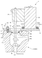
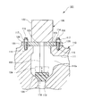
- FIG. 2 is a cross-sectional view (sectional view taken along the line II-II in FIG. 1) showing the structure of the valve seat processing machine according to the first embodiment.
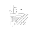
- FIG. 3 is an explanatory diagram (cross-sectional view taken along the line III-III in FIG. 1) showing a method of fixing the pedestal and the main body in the valve seat processing machine according to the first embodiment. It is explanatory drawing (IV-IV arrow cross section in FIG. 1) which shows the press means in the valve seat processing machine which concerns on Example 1.
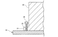
- FIG. FIG. 5 is an explanatory diagram (cross-sectional view taken along the line VV in FIG.
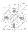
- FIG. 2 shows a vibration isolating ring in the valve seat processing machine according to the first embodiment. It is explanatory drawing which shows the valve seat processing method using the valve seat processing machine which concerns on Example 1. FIG. It is sectional drawing which shows the structure of the valve apparatus which performs the repair process using the valve seat processing machine which concerns on Example 1. FIG.
- FIG. 7 the structure of a valve device that performs repair processing using the valve seat processing machine according to the first embodiment of the present invention will be described.
- the valve device 101 is provided with a valve main body 110 that forms a steam flow path 110 a and is detachably provided on the valve main body 110 to open and close the flow path 110 a in the valve main body 110.
- a valve drive unit 120 that operates a valve body 124 described later is provided.
- the valve device 101 is provided between a boiler (not shown) and a steam turbine (not shown) in the power generation facility, and forms a flow path 110a through which steam supplied from the boiler to the steam turbine flows by the valve main body 110.
- the valve drive unit 120 stops the flow of steam in the flow path 110a and adjusts the flow rate of the steam flowing through the flow path 110a.
- the valve body 110 includes a first opening 111 that opens on one side in the horizontal direction (right side in FIG. 7), and a second opening 112 that opens on one side in the vertical direction (lower side in FIG. 7). And a third opening 113 that opens to the other side in the vertical direction (the upper side in FIG. 7).
- the first opening 111 is connected to a boiler (not shown)
- the second opening 112 is connected to a steam turbine (not shown), and steam generated in the boiler (not shown) It flows into the valve device 101 (valve main body 110) via 111, and then flows out to a steam turbine (not shown) via the second opening 112. That is, the valve body 110 is formed with a flow path 110 a that communicates the first opening 111 and the second opening 112.
- the third opening 113 is formed to communicate with the flow path 110a and to face the second opening 112.
- the third opening 113 is formed so as to face the upper surface 114 of the valve body 110, and the upper surface 114 that the third opening 113 faces is a processed surface that is processed flat.
- a valve driving unit 120 in the valve device 101 is attached to the upper surface 114 of the valve main body 110.
- the valve driving unit 120 includes a mounting plate 121 fixed to the valve main body 110 (upper surface 114), a driving unit main body 122 provided on the mounting plate 121 and having a driving source (not shown), and the driving unit main body 122 in one direction.
- a valve rod 123 and a valve body 124 that are operated in the vertical direction (vertical direction in FIG. 7) are provided.
- a plurality of bolt holes 115 are formed in the vicinity of the third opening 113 on the upper surface 114 of the valve body 110, and stud bolts 116 are screwed into the bolt holes 115, respectively.
- the mounting plate 121 of the valve drive unit 120 is formed with a valve rod insertion hole 125 through which the valve rod 123 can be inserted at a position corresponding to the third opening 113 of the valve main body 110, and the valve main body 110.
- Bolt insertion holes 126 into which the stud bolts 116 can be inserted are formed at positions corresponding to the bolt holes 115 and the stud bolts 116.
- the stud bolt 116 on the upper surface 114 (valve body portion 110) is inserted into the bolt insertion hole 126 of the mounting plate 121 (valve driving portion 120), and the nut 117 is screwed from the tip of the stud bolt 116, whereby the mounting plate 121 ( The valve driving unit 120) is fixed to the upper surface 114 (valve body 110).
- a plurality of bolt holes 115 and stud bolts 116 in the valve main body 110 are provided to surround the third opening 113 and are spaced apart from each other by a predetermined distance in the circumferential direction (see FIG. 1).
- the holes 126 correspond to the bolt holes 115 and the stud bolts 116, that is, a plurality of holes (the same pitch and the same number as the bolt holes 115 and the stud bolts 116) are spaced apart from each other by a predetermined distance in the circumferential direction. Provided (see FIG. 7).
- the drive unit main body 122 is fixed to the mounting plate 121 by fixing means (not shown), and the valve rod 123 is provided from the drive unit main body 122 through the valve rod insertion hole 125 of the mounting plate 121 so as to protrude downward.
- 124 is attached to the tip end side (the lower end side in FIG. 7) of the valve rod 123.
- valve stem 123 and the valve body 124 are configured to operate in the axial direction (vertical direction in FIG. 7) of the valve stem 123 by a drive source (not shown) of the drive unit main body 122.
- a valve seat 118 having a shape corresponding to the valve body 124 is provided in the second opening 112 of the valve body 110, and the valve body 124 is brought into close contact with the valve seat 118 by the operation of the valve driving unit 120. It has become.
- the valve body 124 is in close contact with the valve seat 118, the flow path 110a in the valve main body 110 is closed, and the flow of steam from a boiler (not shown) to a steam turbine (not shown) is stopped.
- valve seat processing machine according to the first embodiment of the present invention will be described with reference to FIGS.
- the valve seat processing machine 1 includes a pedestal portion 10 that is fixed to the valve main body 110 of the valve device 101, and a pedestal portion 10 that is horizontal to the pedestal portion 10.
- a main body 20 that is movable in the X-axis direction (vertical direction in FIG. 1) and the Y-axis direction (left-right direction in FIGS. 1 and 2), and one horizontal side from the main body 20 (leftward in FIGS. 1 and 2)
- a support portion 30 that is movable in the Z-axis direction (vertical direction in FIG. 2) perpendicular to the main body portion 20 and a front end side of the support portion 30 (left end side in FIGS.
- a main shaft 40 that is movable in the vertical W-axis direction (vertical direction in FIG. 2) with respect to the support portion 30 and supported so as to be rotatable about the vertical C-axis, and a tip portion of the main shaft 40 It is provided at (the lower end in FIG. 2) and holds the cutting tool T Summary composed ingredients holder 50..
- This valve seat processing machine 1 is for repairing the valve seat 118 when the valve seat 118 of the valve device 101 is eroded by erosion.
- the valve seat processing machine 1 replaces the valve drive unit 120 (see FIG. 7) with a valve. It is assembled to the valve body 110 of the device 101. That is, the valve seat processing machine 1 is movable, and the valve seat 118 can be repaired in a state where the valve device 101 (the valve main body 110) is assembled to a boiler (not shown) and a steam turbine (not shown). It can be done.
- the pedestal portion 10 of the valve seat processing machine 1 has a flat plate shape in which a circular portion 11 and a rectangular portion 12 are combined (see FIG. 1). It is fixed to the valve main body 110 of the valve device 101, and the main body 20 of the valve seat processing machine 1 is fixed to the pedestal 10 in the rectangular portion 12 (see FIGS. 1 and 2).
- the main shaft 40 can be inserted into the circular portion 11 of the pedestal portion 10 (having substantially the same diameter as the third opening 113 and having a larger diameter than the third opening 113 in FIGS. 1 and 2).
- a through hole 13 and a plurality (twelve in FIG. 1) of bolt through holes 14 through which the stud bolts 116 can be inserted are provided.
- the main shaft through hole 13 is formed at a position corresponding to the third opening 113, and the plurality of bolt through holes 14 are located at positions corresponding to the bolt hole 115 and the stud bolt 116 of the valve device 101, that is, the main shaft through hole 13.
- a plurality (the same pitch and the same number as the bolt holes 115 and the stud bolts 116) are provided so as to surround and be separated by a predetermined distance in the circumferential direction.
- valve The seat processing machine 1 By inserting the stud bolt 116 of the valve main body 110 in the valve device 101 into the bolt through hole 14 of the base 10 in the valve seat processing machine 1 and screwing the nut 15 from the tip of the stud bolt 116, the base 10 (valve The seat processing machine 1) can be fixed to the valve body 110 (valve device 101).
- the plurality of stud bolts 116 in the valve device 101 and the plurality of bolt through holes 14 in the valve seat processing machine 1 are provided at the same pitch and the same number, Even if the valve seat processing machine 1 is rotated by one pitch (or a plurality of pitches), the stud bolt 116 of the valve device 101 can be inserted into the bolt through hole 14 of the base portion 10. Therefore, the base part 10 (valve seat processing machine 1) can be assembled to the valve main body part 110 (valve device 101) while shifting the phase every pitch.
- valve seat processing machine 1 can be assembled to the valve device 101 (valve body 110) while avoiding interference with the valve seat processing machine 1.
- the main body 20 of the valve seat processing machine 1 is provided with flanges 21 at symmetrical positions (upper and lower sides in FIG. 1).
- the flange portion 21 is pressed by the pressing bracket 23 and the bolt 24 together with the liner 22 formed at substantially the same height as the flange 21 (vertical length in FIG. 3). It is fixed to.
- the pedestal portion 10 is provided with protrusions 16 and 17 located around the main body portion 20 (four directions in FIG. 1).
- X-axis direction position adjusting bolts 18 are screwed into the protrusions 16 positioned on both sides (upper side and lower side in FIG. 1) of the main body 20 in the horizontal X-axis direction.
- Y-axis direction position adjusting bolts 19 are screwed into the protrusions 17 located on both sides (the left side and the right side in FIG. 1) of the main body 20 in the horizontal Y-axis direction.
- the main body 20 can be moved in the Y-axis direction on the pedestal 10. That is, the position of the main body 20 with respect to the pedestal 10 in the horizontal plane (XY plane) can be adjusted by the X-axis direction position adjusting bolt 18 and the Y-axis direction position adjusting bolt 19.
- the main body 20 has a plurality (four in FIG. 1) of screw holes 25 penetrating the flange 21 in the vertical direction (vertical direction in FIG. 4).
- the push-up bolts 26 are screwed into the screw holes 25, respectively.
- the main body 20 can be lifted with respect to the base 10, that is, a gap can be formed between the base 10 and the main body 20.
- a height adjustment liner (not shown) is inserted into the gap (between the pedestal 10 and the main body 20). can do.
- the X-axis direction position, the Y-axis direction position and the inclination of the main body portion 20 can be adjusted, so that the main shaft 40 is centered on the valve seat 118. It is possible to perform an accurate processing that matches the above.
- the main body 20 is fixed to the pedestal 10 in a state where the X-axis direction position, the Y-axis direction position, and the inclination are adjusted. Can be fixed to.
- the main shaft 40 is provided with a vibration isolating ring 41 that is rotatably supported.
- the anti-vibration ring 41 can prevent the main shaft 40 from swinging (vibrating or wobbling) due to processing resistance or the like during processing with the cutting tool T provided at the tip of the main shaft 40.
- a plurality of (four in FIG. 5) projecting bolts 41b that can project to the outer peripheral side of the ring section 41a.
- the anti-vibration ring 41 is, for example, inside the third opening 113 while allowing the rotation of the main shaft 40 around the C axis by adjusting the amount of protrusion from the ring portion 41a by screwing the protruding bolt 41b. Fixed.
- valve seat processing method using the valve seat processing machine according to the first embodiment of the present invention will be described with reference to FIGS.
- valve drive unit 120 assembled to the valve main body 110 in the valve device 101 is removed (see FIG. 7), and the valve seat processing machine 1 is replaced with the valve main body 110 of the valve device 101 in place of the valve drive unit 120.
- Assemble see FIG. 2. That is, by inserting the stud bolt 116 installed in the valve main body 110 into the bolt through hole 14 of the pedestal portion 10 and screwing the nut 15 into the stud bolt 116, the pedestal portion 10 in the processing machine 1 is in the valve device 101. It is fixed to the valve body 110.
- the valve seat processing machine 1 is installed in consideration of interference with the other devices and workability. Since the plurality of bolt through holes 14 provided in the pedestal portion 10 are provided at the same pitch and the same number as the stud bolts 116, the mounting direction of the valve seat processing machine 1 (pedestal portion 10) with respect to the valve device 101 (rectangular portion) 12 can be set in various directions, so that the valve seat processing machine 1 can be installed in consideration of interference with other devices (not shown) and workability (see FIG. 1).
- the position (X-axis direction position and Y-axis direction position) and inclination of the main body 20 in the horizontal plane with respect to the pedestal 10 are adjusted. That is, the X-axis direction position adjustment bolt 18 and the Y-axis direction position adjustment bolt 19 adjust the X-axis direction position and the Y-axis direction position of the main body portion 20 with respect to the pedestal portion 10 (see FIGS. 1 and 2).
- the main body 20 is lifted by 26 and a height adjusting liner (not shown) is inserted to adjust the inclination of the main body 20 with respect to the pedestal 10 (the inclination of the main shaft 40 with respect to the vertical direction) (see FIGS. 1 and 4).
- dial gauges are attached to two different locations in the axial direction of the main shaft 40 (vertical direction in FIG. 2), and the dial gauge is attached to the valve seat 118 and the third valve body 110 of the valve device 101. Based on the measurement data obtained by pressing against the inner peripheral side of the opening 113, the X-axis direction position, the Y-axis direction position, and the tilt adjustment amount of the main body 20 can be obtained.
- the main body 20 is fixed to the pedestal 10. That is, as shown in FIG. 3, the liner 22 is installed in the vicinity of the flange 21 in the main body 20, and the flange 21 and the liner 22 are pressed by the pressing metal 23 and the bolts 24, so that the main body 20 is fixed to the pedestal 10. Secure to.
- the vibration isolating ring 41 provided on the main shaft 40 is fixed inside the third opening 113. That is, the vibration isolating ring 41 engaged with the main shaft 40 is moved in the axial direction (vertical direction in FIG. 2) to be aligned with the position of the third opening 113, and the projecting bolt 41b is adjusted to adjust the vibration isolating ring 41. It fixes to the inner side of the 3rd opening part 113 (refer FIG. 2 and FIG. 5).
- valve device 101 is repaired by the valve seat processing machine 1.
- the spindle 40 is driven to rotate while the cutting tool T 1 for cutting the range a 1 in the valve seat 118 is held by the tool holder 50, and the support portion 30 is moved in the Z-axis direction.
- the support portion 30 is moved downward so that the eroded portion of the valve seat 118 can be removed.
- the cutting tools T 2 , T 3 , T 4 , and T 5 for cutting the ranges a 2 , a 3 , a 4 , and a 5 in the valve seat 118 are held by the tool holder 50, respectively.
- the ranges a 2 , a 3 , a 4 , and a 5 in the valve seat 118 are cut.
- the plurality of ranges a 1 to a 5 in the valve seat 118 are respectively cut using the plurality of cutting tools T 1 to T 5 having different shapes of the cutting blades, whereby the entire valve seat 118 (all The range a 1 to a 5 ) can be repaired. That is, the valve seat 118 can have a shape corresponding to the valve body 124 (see FIG. 7).
- valve seat 118 it is possible to easily repair the valve seat 118 in a state where the valve device 101 (the valve main body 110) is assembled to a boiler (not shown) and a steam turbine (not shown).
- Valve seat processing machine 10 Base part 11 of valve seat processing machine Circular part 12 Square part 13 Main shaft through hole 14 Bolt through hole 15 Nut 16 Projection part 17 Projection part 18 X-axis direction position adjustment bolt 19 Y-axis direction position adjustment bolt 20 Body part 21 of valve seat processing machine Flange 22 Liner 23 Press fitting 24 Bolt 25 Screw hole 26 Push-up bolt (pressing means) 30 Valve seat processing machine support section 40 Valve seat processing machine spindle 41 Anti-vibration ring (ring member) 41a Ring part 41b of vibration isolating ring Projecting bolt 50 of vibration isolating ring Tool holder 101 Valve device 110 Valve body 110a Flow path 111 First opening 112 Second opening 113 Third opening 114 Upper surface 115 Bolt hole 116 Stud bolt 117 Nut 118 Valve Seat 120 Valve Drive Unit 121 Mounting Plate 122 Drive Unit Body 123 Valve Rod 124 Valve Element 125 Valve Rod Insertion Hole 126 Bolt Insertion Hole
Landscapes
- Engineering & Computer Science (AREA)
- Mechanical Engineering (AREA)
- General Engineering & Computer Science (AREA)
- Turning (AREA)
- Lift Valve (AREA)
- Drilling And Boring (AREA)
Abstract
Description
また、工具ホルダに切削刃の形状を異にする複数の切削工具を付け替えて弁座の加工を行うことにより、弁座を弁体に対応した形状に容易に加工することができる。 According to the valve seat processing method according to the fifth aspect of the invention, when the valve seat of the valve device is eroded by erosion, the valve seat processing machine can be assembled to the valve main body portion of the valve device instead of the valve drive portion. The valve seat can be repaired in a state where the valve device (valve body portion) is assembled to a turbine or the like. Therefore, in the repair work of the valve seat in the valve device, the removal work of the valve device from the turbine, the attachment work to the turbine, etc., and the transportation work between the factory with the power generation equipment and the factory with the processing equipment can be eliminated. it can.
In addition, the valve seat can be easily processed into a shape corresponding to the valve body by replacing the plurality of cutting tools having different shapes of the cutting blades with the tool holder and processing the valve seat.
10 弁座加工機の台座部
11 円形部
12 方形部
13 主軸通し穴
14 ボルト通し穴
15 ナット
16 突出部
17 突出部
18 X軸方向位置調整ボルト
19 Y軸方向位置調整ボルト
20 弁座加工機の本体部
21 フランジ
22 ライナ
23 押し付け金具
24 ボルト
25 ねじ穴
26 押し上げボルト(押圧手段)
30 弁座加工機の支持部
40 弁座加工機の主軸
41 防振リング(リング部材)
41a 防振リングのリング部
41b 防振リングの突出ボルト
50 工具ホルダ
101 弁装置
110 弁本体部
110a 流路
111 第一開口部
112 第二開口部
113 第三開口部
114 上面
115 ボルト穴
116 スタッドボルト
117 ナット
118 弁座
120 弁駆動部
121 取付板
122 駆動部本体
123 弁棒
124 弁体
125 弁棒挿通穴
126 ボルト挿通穴 DESCRIPTION OF SYMBOLS 1 Valve
30 Valve seat processing
Claims (5)
- 流体の流路を形成する弁本体部と、前記弁本体部に着脱可能に設けられて前記弁本体部における弁座に密着係合可能な弁体を駆動することによって前記流路を開閉する弁駆動部とを備えた弁装置における前記弁座を加工する弁座加工機であって、
前記弁本体部に取り付けられる台座部と、
前記台座部に設けられ、当該台座部に対して異なる二軸方向に移動可能な本体部と、
前記本体部に設けられ、当該本体部に対して前記弁体の駆動方向に移動可能な支持部と、
前記支持部に設けられ、当該支持部に対して前記弁体の駆動方向と平行な軸回りに回動可能な主軸と、
前記主軸に設けられ、前記弁座を加工するための工具を保持する工具ホルダと
を備えたことを特徴とする弁座加工機。 A valve body part that forms a fluid flow path, and a valve that opens and closes the flow path by driving a valve body that is detachably provided on the valve body part and is capable of closely engaging with a valve seat in the valve body part A valve seat processing machine for processing the valve seat in a valve device including a drive unit,
A pedestal portion attached to the valve body portion;
A main body provided on the pedestal and movable in different biaxial directions with respect to the pedestal;
A support portion that is provided in the main body portion and is movable with respect to the main body portion in the driving direction of the valve body;
A main shaft provided in the support portion and rotatable about an axis parallel to the driving direction of the valve body with respect to the support portion;
A valve seat processing machine comprising: a tool holder that is provided on the main shaft and holds a tool for processing the valve seat. - 前記台座部が、前記弁本体部に設けられた既設のボルト穴と同ピッチ且つ同数のボルト挿通穴を有するものである
ことを特徴とする請求項1に記載の弁座加工機。 2. The valve seat processing machine according to claim 1, wherein the pedestal part has the same pitch and the same number of bolt insertion holes as existing bolt holes provided in the valve main body part. - 前記主軸の外周側に回転可能に取り付けられ、前記弁本体部に固定可能なリング部材を備えた
ことを特徴とする請求項1または請求項2に記載の弁座加工機。 The valve seat processing machine according to claim 1 or 2, further comprising a ring member rotatably attached to an outer peripheral side of the main shaft and capable of being fixed to the valve main body. - 前記本体部が、前記台座部を押圧して当該本体部と前記台座部との間に隙間を形成する押圧手段を備えたものである
ことを特徴とする請求項1から請求項3のいずれか一項に記載の弁座加工機。 The said main-body part is provided with the press means which presses the said base part and forms a clearance gap between the said main-body part and the said base part. The any one of Claims 1-3 characterized by the above-mentioned. The valve seat processing machine according to one item. - 流体の流路を形成する弁本体部と、前記弁本体部に着脱可能に設けられて前記弁本体部における弁座に密着係合可能な弁体を駆動することによって前記流路を開閉する弁駆動部とを備えた弁装置における前記弁座を加工する弁座加工方法であって、
前記弁本体部から前記弁駆動部を取り外し、前記弁本体部に請求項1から請求項4のいずれか一項に記載の弁座加工機を取り付け、前記工具ホルダに切削刃の形状を異にする複数の切削工具を付け替えることにより、前記弁座を前記弁体に対応した形状に加工する
ことを特徴とする弁座加工方法。 A valve body part that forms a fluid flow path, and a valve that opens and closes the flow path by driving a valve body that is detachably provided on the valve body part and is capable of closely engaging with a valve seat in the valve body part A valve seat processing method for processing the valve seat in a valve device including a drive unit,
The said valve drive part is removed from the said valve main-body part, the valve seat processing machine as described in any one of Claims 1-4 is attached to the said valve main-body part, and the shape of the cutting blade differs in the said tool holder. A valve seat machining method comprising: machining the valve seat into a shape corresponding to the valve body by changing a plurality of cutting tools.
Priority Applications (5)
| Application Number | Priority Date | Filing Date | Title |
|---|---|---|---|
| EP16811631.7A EP3156159B1 (en) | 2015-06-16 | 2016-06-15 | Valve seat machining device, and valve seat machining method using said valve seat machining device |
| CN201680002007.4A CN106488822B (en) | 2015-06-16 | 2016-06-15 | Valve seat processing machine and the valve seat processing method using the valve seat processing machine |
| ES16811631.7T ES2689487T3 (en) | 2015-06-16 | 2016-06-15 | Valve seat machining device and valve seat machining method using said valve seat machining device |
| KR1020167033630A KR101726985B1 (en) | 2015-06-16 | 2016-06-15 | Valve seat processing machine and valve seat processing method using the same |
| US15/325,259 US10010995B2 (en) | 2015-06-16 | 2016-06-15 | Valve seat machining device, and valve seat machining method using said valve seat machining device |
Applications Claiming Priority (2)
| Application Number | Priority Date | Filing Date | Title |
|---|---|---|---|
| JP2015120764A JP5881884B1 (en) | 2015-06-16 | 2015-06-16 | Valve seat processing machine and valve seat processing method using the valve seat processing machine |
| JP2015-120764 | 2015-06-16 |
Publications (1)
| Publication Number | Publication Date |
|---|---|
| WO2016204157A1 true WO2016204157A1 (en) | 2016-12-22 |
Family
ID=55453380
Family Applications (1)
| Application Number | Title | Priority Date | Filing Date |
|---|---|---|---|
| PCT/JP2016/067722 WO2016204157A1 (en) | 2015-06-16 | 2016-06-15 | Valve seat machining device, and valve seat machining method using said valve seat machining device |
Country Status (7)
| Country | Link |
|---|---|
| US (1) | US10010995B2 (en) |
| EP (1) | EP3156159B1 (en) |
| JP (1) | JP5881884B1 (en) |
| KR (1) | KR101726985B1 (en) |
| CN (1) | CN106488822B (en) |
| ES (1) | ES2689487T3 (en) |
| WO (1) | WO2016204157A1 (en) |
Families Citing this family (9)
| Publication number | Priority date | Publication date | Assignee | Title |
|---|---|---|---|---|
| US10717166B2 (en) * | 2016-12-02 | 2020-07-21 | General Electric Company | Motorized apparatus for use with rotary machines |
| US11306605B2 (en) * | 2017-04-28 | 2022-04-19 | Siemens Energy, Inc. | Automated reheat stop valve seat restoration |
| CN108361394B (en) * | 2018-02-11 | 2020-04-14 | 中广核核电运营有限公司 | Positioning and mounting device and positioning and mounting system of high-pressure valve |
| CN108393522B (en) * | 2018-02-11 | 2020-03-20 | 中广核核电运营有限公司 | Guide rail cutting device and cutting method of high-altitude valve |
| CN108356335B (en) * | 2018-02-11 | 2021-01-26 | 中广核核电运营有限公司 | Valve seat girth weld cutting system of high-pressure valve and cutting device thereof |
| CN108247232B (en) * | 2018-02-11 | 2020-10-16 | 中广核核电运营有限公司 | Valve seat girth weld welding system of high-pressure valve and welding device thereof |
| CN109719589B (en) * | 2018-12-20 | 2021-03-09 | 中国海洋石油集团有限公司 | Grinding and repairing device for sealing surface of safety valve |
| KR102192955B1 (en) * | 2019-09-23 | 2020-12-18 | 주식회사 삼신 | Method for repair welding of seat ring for power plant |
| KR102628051B1 (en) * | 2021-11-12 | 2024-01-23 | 두산에너빌리티 주식회사 | Apparatus for welding seat ring of valve of power plant |
Citations (6)
| Publication number | Priority date | Publication date | Assignee | Title |
|---|---|---|---|---|
| JPS5328892A (en) * | 1976-08-30 | 1978-03-17 | Toshiba Corp | Device for cutting valve body |
| JPS55151401U (en) * | 1979-04-16 | 1980-10-31 | ||
| JPS6199402U (en) * | 1984-12-07 | 1986-06-25 | ||
| JPH04244301A (en) * | 1991-01-30 | 1992-09-01 | Toa Valve Kk | Valve seat machining device for gate valve, check valve, etc. |
| JP3021143U (en) * | 1995-07-31 | 1996-02-16 | 岡野バルブ製造株式会社 | Valve seat surface repair device |
| JP2006239836A (en) * | 2005-03-04 | 2006-09-14 | Chugoku Electric Power Co Inc:The | Valve seat lapping device |
Family Cites Families (21)
| Publication number | Priority date | Publication date | Assignee | Title |
|---|---|---|---|---|
| US801350A (en) * | 1904-04-25 | 1905-10-10 | Leavitt Machine Co | Valve-reseating machine. |
| US1186403A (en) * | 1915-08-30 | 1916-06-06 | Sigurd Halvdan Johnsen | Tool for shaping valve-seats. |
| CH286950A (en) * | 1950-04-15 | 1952-11-15 | Ag Edm Gressel | Machine for grinding valve seats. |
| DE2454909A1 (en) * | 1974-11-20 | 1976-05-26 | Modranske Strojirny N P | Semi automatic grinding machine for grinding and lapping - consists of housing with working plate, centralising plate, spindle and hydraulic drive |
| US4114483A (en) * | 1977-04-08 | 1978-09-19 | Grimsley Ernest E | Portable boring tool for ball valves |
| US4090805A (en) * | 1977-07-28 | 1978-05-23 | Grimsley Ernest E | Cutting tool for removing governor chest nozzles and refinishing the nozzle seats |
| US4205495A (en) * | 1977-10-07 | 1980-06-03 | Grimsley Ernest E | Adapter means for a valve reseating tool |
| US4175471A (en) * | 1977-12-19 | 1979-11-27 | The United States Of America As Represented By The Secretary Of The Navy | Cutting apparatus and vertical drive mechanism therefor |
| US4234275A (en) * | 1978-07-26 | 1980-11-18 | Clement Michael H | Method and apparatus for mounting an engine block boring machine |
| US4468158A (en) * | 1982-11-29 | 1984-08-28 | The United States Of America As Represented By The Secretary Of The Navy | Inplace ball valve repair apparatus |
| US4585376A (en) * | 1984-05-14 | 1986-04-29 | Davenport Sr William R | Safe lock drilling apparatus |
| FR2623434B1 (en) * | 1987-11-25 | 1990-04-06 | Etude Realisa Diffusion Indles | TOOL HOLDER FOR VALVE SEAT GRINDING MACHINE |
| US5125299A (en) * | 1990-05-10 | 1992-06-30 | Climax Portable Machine Tools, Inc. | Portable machine tool |
| US5030046A (en) * | 1990-06-25 | 1991-07-09 | Ricci Donato L | Valve seal ring seating machine |
| JPH09192998A (en) * | 1996-01-17 | 1997-07-29 | Nishi Nippon Plant Kogyo Kk | Valve seat lapping device |
| KR200426772Y1 (en) * | 2006-07-03 | 2006-09-20 | 이정열 | Device for treating an engine valve seat |
| CN201291407Y (en) * | 2008-11-25 | 2009-08-19 | 沈阳市北陵多元机电研究所 | Grinding device for sealing surface of valve base of high-temperature, high-pressure valve |
| DE102009046401B4 (en) * | 2009-11-04 | 2012-08-09 | Areva Np Gmbh | Method and device for processing a sealing seat of a shut-off valve |
| JP5368965B2 (en) * | 2009-12-17 | 2013-12-18 | 富士精工株式会社 | Valve seat machining tool |
| US20130183114A1 (en) * | 2012-01-13 | 2013-07-18 | Ricardo Bermea | Multiple angle valve seat cutter blades and method |
| JP6076823B2 (en) | 2013-04-26 | 2017-02-08 | 株式会社東芝 | Steam valve device |
-
2015
- 2015-06-16 JP JP2015120764A patent/JP5881884B1/en active Active
-
2016
- 2016-06-15 WO PCT/JP2016/067722 patent/WO2016204157A1/en active Application Filing
- 2016-06-15 ES ES16811631.7T patent/ES2689487T3/en active Active
- 2016-06-15 US US15/325,259 patent/US10010995B2/en active Active
- 2016-06-15 EP EP16811631.7A patent/EP3156159B1/en active Active
- 2016-06-15 KR KR1020167033630A patent/KR101726985B1/en active IP Right Grant
- 2016-06-15 CN CN201680002007.4A patent/CN106488822B/en active Active
Patent Citations (6)
| Publication number | Priority date | Publication date | Assignee | Title |
|---|---|---|---|---|
| JPS5328892A (en) * | 1976-08-30 | 1978-03-17 | Toshiba Corp | Device for cutting valve body |
| JPS55151401U (en) * | 1979-04-16 | 1980-10-31 | ||
| JPS6199402U (en) * | 1984-12-07 | 1986-06-25 | ||
| JPH04244301A (en) * | 1991-01-30 | 1992-09-01 | Toa Valve Kk | Valve seat machining device for gate valve, check valve, etc. |
| JP3021143U (en) * | 1995-07-31 | 1996-02-16 | 岡野バルブ製造株式会社 | Valve seat surface repair device |
| JP2006239836A (en) * | 2005-03-04 | 2006-09-14 | Chugoku Electric Power Co Inc:The | Valve seat lapping device |
Also Published As
| Publication number | Publication date |
|---|---|
| EP3156159A4 (en) | 2017-06-14 |
| EP3156159B1 (en) | 2018-08-29 |
| US10010995B2 (en) | 2018-07-03 |
| US20170182623A1 (en) | 2017-06-29 |
| JP5881884B1 (en) | 2016-03-09 |
| KR101726985B1 (en) | 2017-04-13 |
| EP3156159A1 (en) | 2017-04-19 |
| KR20170002530A (en) | 2017-01-06 |
| CN106488822B (en) | 2018-03-16 |
| JP2017001169A (en) | 2017-01-05 |
| CN106488822A (en) | 2017-03-08 |
| ES2689487T3 (en) | 2018-11-14 |
Similar Documents
| Publication | Publication Date | Title |
|---|---|---|
| JP5881884B1 (en) | Valve seat processing machine and valve seat processing method using the valve seat processing machine | |
| JP5881883B1 (en) | Valve seat processing machine and valve seat processing method using the valve seat processing machine | |
| JP6000485B1 (en) | Seal surface processing machine and method | |
| AU2019101619A4 (en) | A Fixed Device for Conveniently Installing Robot Arms | |
| KR101559306B1 (en) | Apparatus for processing an inner face of casing | |
| JP7053142B2 (en) | Portable mill tools and milling methods | |
| JP4700590B2 (en) | Horizontal machining center | |
| JP3213863U (en) | Processing machine support device and processing machine | |
| JP5979037B2 (en) | Rotary table device and machine tool | |
| JP2003001508A (en) | Processing device for removing bolt by counterboring | |
| WO2015197538A1 (en) | Device for bracing in a cavity and method for mounting the device | |
| KR101264803B1 (en) | Gig assembly and propeller of a ship manufacturing apparatus having the same | |
| KR20170101564A (en) | A processing apparatus for flange | |
| KR20150020600A (en) | Valve machining device and method for machining a valve | |
| JP4479523B2 (en) | Processing apparatus and processing method | |
| JP2016059987A (en) | Fastening mechanism and fastening method | |
| KR20240003273A (en) | Processing apparatus of groove and processing method thereof | |
| JP5683921B2 (en) | Gasket bearing surface repair device and repair method | |
| KR101264802B1 (en) | Gig assembly and propeller of a ship manufacturing apparatus having the same | |
| JP2016002600A (en) | Distribution ball inner sheet surface process machine, distribution ball inner sheet surface measurement device, distribution ball inner sheet surface process measurement device, distribution ball inner sheet surface processing method, distribution ball inner sheet surface process measurement method, and distribution ball inner sheet surface measurement processing method | |
| JPH04275801A (en) | Portable internal face machining apparatus |
Legal Events
| Date | Code | Title | Description |
|---|---|---|---|
| ENP | Entry into the national phase |
Ref document number: 20167033630 Country of ref document: KR Kind code of ref document: A |
|
| WWE | Wipo information: entry into national phase |
Ref document number: 15325259 Country of ref document: US |
|
| REEP | Request for entry into the european phase |
Ref document number: 2016811631 Country of ref document: EP |
|
| WWE | Wipo information: entry into national phase |
Ref document number: 2016811631 Country of ref document: EP |
|
| 121 | Ep: the epo has been informed by wipo that ep was designated in this application |
Ref document number: 16811631 Country of ref document: EP Kind code of ref document: A1 |
|
| NENP | Non-entry into the national phase |
Ref country code: DE |