WO2016203995A1 - 電源システムおよび充電ステーション - Google Patents
電源システムおよび充電ステーション Download PDFInfo
- Publication number
- WO2016203995A1 WO2016203995A1 PCT/JP2016/066581 JP2016066581W WO2016203995A1 WO 2016203995 A1 WO2016203995 A1 WO 2016203995A1 JP 2016066581 W JP2016066581 W JP 2016066581W WO 2016203995 A1 WO2016203995 A1 WO 2016203995A1
- Authority
- WO
- WIPO (PCT)
- Prior art keywords
- electrode plate
- power supply
- power
- band electrode
- ion capacitor
- Prior art date
- Legal status (The legal status is an assumption and is not a legal conclusion. Google has not performed a legal analysis and makes no representation as to the accuracy of the status listed.)
- Ceased
Links
Images









Classifications
-
- H—ELECTRICITY
- H02—GENERATION; CONVERSION OR DISTRIBUTION OF ELECTRIC POWER
- H02J—ELECTRIC POWER NETWORKS; CIRCUIT ARRANGEMENTS OR SYSTEMS FOR SUPPLYING OR DISTRIBUTING ELECTRIC POWER; SYSTEMS FOR STORING ELECTRIC ENERGY
- H02J7/00—Circuit arrangements for charging or discharging batteries or for supplying loads from batteries
-
- H—ELECTRICITY
- H02—GENERATION; CONVERSION OR DISTRIBUTION OF ELECTRIC POWER
- H02J—ELECTRIC POWER NETWORKS; CIRCUIT ARRANGEMENTS OR SYSTEMS FOR SUPPLYING OR DISTRIBUTING ELECTRIC POWER; SYSTEMS FOR STORING ELECTRIC ENERGY
- H02J50/00—Circuit arrangements or systems for wireless supply or distribution of electric power
- H02J50/05—Circuit arrangements or systems for wireless supply or distribution of electric power using capacitive coupling
-
- H—ELECTRICITY
- H02—GENERATION; CONVERSION OR DISTRIBUTION OF ELECTRIC POWER
- H02J—ELECTRIC POWER NETWORKS; CIRCUIT ARRANGEMENTS OR SYSTEMS FOR SUPPLYING OR DISTRIBUTING ELECTRIC POWER; SYSTEMS FOR STORING ELECTRIC ENERGY
- H02J7/00—Circuit arrangements for charging or discharging batteries or for supplying loads from batteries
- H02J7/34—Parallel operation in networks using both storage and other DC sources, e.g. providing buffering
-
- H—ELECTRICITY
- H02—GENERATION; CONVERSION OR DISTRIBUTION OF ELECTRIC POWER
- H02J—ELECTRIC POWER NETWORKS; CIRCUIT ARRANGEMENTS OR SYSTEMS FOR SUPPLYING OR DISTRIBUTING ELECTRIC POWER; SYSTEMS FOR STORING ELECTRIC ENERGY
- H02J9/00—Circuit arrangements for emergency or stand-by power supply, e.g. for emergency lighting
- H02J9/04—Circuit arrangements for emergency or stand-by power supply, e.g. for emergency lighting in which the distribution system is disconnected from the normal source and connected to a standby source
- H02J9/06—Circuit arrangements for emergency or stand-by power supply, e.g. for emergency lighting in which the distribution system is disconnected from the normal source and connected to a standby source with automatic change-over, e.g. UPS systems
Definitions
- the present invention relates to a power supply system and a charging station including a DC power supply, and more particularly to a power supply system and a charging station configured to include a LIC (lithium ion capacitor) as a DC power supply.
- a LIC lithium ion capacitor
- the power supply system is widely applied and used in various various industrial facilities, household facilities, or mobile facilities.
- the power supply system in this case is a power supply system for various devices (loads) in the facility, and is generally composed of an AC power supply (AC), a DC power supply (DC), or both.
- AC AC
- DC DC
- the power supply system may be configured to include an uninterruptible power supply UPS (UPS has a mixed meaning here, but the description is omitted).
- UPS uninterruptible power supply
- a typical example of industrial equipment to which a power supply system is applied is, for example, a power supply system for a power plant.
- the power supply systems in power plants are publicly recognized as having AC power supply (AC) and DC power supply (DC) that have been established for operation over many years. AC or DC power is supplied.
- the power generation function as a whole is demonstrated by the proper operation of the auxiliary machinery group around the main engine. Is maintained.
- the power plant is generally an AC power generation system, most of them are AC (AC) power supply types except for some DC auxiliary machines, DC excitation systems, and DC control system power supplies.
- the power source of the power plant is configured mainly with an AC power source in normal operation, but is configured to include a DC power source for emergency operation.
- an emergency DC power auxiliary oil pump
- an emergency configuration with a DC power supply is used.
- most of the DC power sources are configured to include a storage battery.
- a lithium ion capacitor LIC (hereinafter simply referred to as LIC) with high energy density and improved safety performance is provided as a new DC power supply, and supply and absorption to the DC load in the power plant is executed with high response. It has been studied to perform power supply support (assist) to the load.
- Patent Document 1 discloses a technology relating to a power storage system and a power storage method for storing electrostatic energy using a potential gradient in the atmosphere as a power storage system and a power storage method for LIC.
- the function expected from the DC power source including the storage battery, or the requirement of the operation specifications for this configuration is the minimum load that is urgent and indispensable when all the AC power sources in the station are lost. , Power supply to the equipment.
- auxiliary machine stop due to AC power supply interruption and an instantaneous power supply for the resulting decrease in hydraulic pressure, and the accelerating machine (pump) for storage battery power supply is started for the fastest response.
- the equipment is configured as a circuit. In this case, a large starting current is generated in the auxiliary machine due to a rapid rise in the load of the storage equipment, but this is inevitably but not rational because it imposes restrictions on determining the specifications of the storage battery equipment. .
- the AC power source in the power plant is converted into a DC power source, and this generally uses the power obtained by the power generation. For this reason, it is the result of causing the efficiency fall as the whole power plant.
- the present invention has an object to provide a power supply system and a charging station that take advantage of its characteristics by providing a LIC as a new DC power supply.
- the present invention includes a plurality of means for solving the above-mentioned problems.
- a power supply system including a first power supply and a DC power supply for supplying power to a load facility, the DC power supply being a lithium ion capacitor And supplying power to the load facility by discharging from a lithium ion capacitor.
- the present invention is also a charging station comprising a power supply system mounted on a moving body and supplying a load with a DC power supply and an outdoor facility, and the outdoor facility is charged with a potential difference between an installation position and a grounding point. And a height adjusting means for determining the height position between the band electrode plate installation position and the moving body, the DC power source is electrically connected to the band electrode plate, A lithium ion capacitor that moves a charged charge and stores the charge, and a switch provided between the strip electrode plate and the lithium ion capacitor, the electrical connection between the strip electrode plate and the lithium ion capacitor A switch that can be cut off, a voltage of the band electrode plate, or an electrode plate voltage calculation unit that calculates the amount of charge charged to the band electrode plate, and a voltage of the band electrode plate obtained by the electrode plate voltage calculation unit, Or And controls the opening and closing of the switch according to the charge amount of the charging electrode plate, a charging station, characterized in that it comprises a control unit for moving the charged charge to charging electrode plate to a
- the LIC as a new DC power supply, it is possible to provide a power supply system and a charging station that take advantage of the characteristics, and further contribute to the improvement of the overall plant efficiency due to the contribution from natural energy.
- the figure which shows the basic composition of the power supply system 100 of this invention The figure which shows the example of the power supply system 100 suitable for applying to a general plant (factory etc.) and the in-house power supply equipment in a power plant. The figure which shows the example of the power supply system 100 suitable for applying to the power supply equipment for home use. The figure explaining the usage of LIC. The figure which shows the 1st usage example 201 of LIC. The figure which showed in detail the specific structural example of the power supply system with respect to DC power supply equipment in a power plant. The figure which showed the case where the electrical storage from AC power supply to LIC is performed. The figure which showed the case where the electrical storage from an atmospheric electric field to LIC was performed.
- FIG. 10 is a diagram illustrating a further application development example of the LIC according to the fourth embodiment.
- the figure which imaged the non-contact charge station when the object to be charged is a moving body such as an automobile.
- the present invention is a power supply system including a DC power supply, and in particular, a power supply system including a LIC as a DC power supply.
- the power supply system including the DC power supply of the present invention can be applied as a power supply system for various uses (industrial equipment, household equipment, mobile equipment, etc.).
- Various arrangements and usages of the LIC can be applied. For this reason, an example of a schematic configuration of a power supply system including the LIC will be described first.
- an AC power supply bus BUSAC an AC power supply bus BUSAC, a converter CON that converts power from AC to DC, a DC bus BUSDC, and a distribution board Bd are illustrated.
- DC power is supplied to the DC load.
- the DC side of the converter CON is connected to the DC battery Bt, and the DC power stored in the DC battery Bt is supplied from the DC battery Bt to the in-house load as needed via the distribution board Bd.
- the power supply system 100 itself supplies DC power to a DC load (not shown), and the entire configuration 100 can be said to be a DC power supply in a broad sense.
- the power supply unit in the narrow sense that is, when the AC power supply is lost, is referred to as the DC power supply 200.
- the DC power source 200 includes a DC battery Bt.
- a LIC is additionally installed on the DC battery Bt, which is a basic DC power source facility.
- FIG. 1 discloses the basic configuration of the power supply system 100 of the present invention. Therefore, it is possible to configure the power supply system 100 by additionally installing various types of equipment on the basis of this configuration or by deleting a part of them.
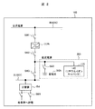
- FIG. 2 shows an example of a power supply system 100 suitable for application to a general plant (such as a factory) or an in-house power supply facility in a power plant.
- AC power supply bus BUSAC, converter CON, DC bus BUSDC, distribution board Bd, etc. are connected through appropriate switches SW (SW1 to SW5) to supply DC power to a DC load (not shown).
- SW switches SW (SW1 to SW5) to supply DC power to a DC load (not shown).
- FIG. 1 The difference from FIG. 1 is that a switch for switching is arranged in various places and a storage battery StBt is arranged instead of the DC battery Bt as a basic DC power supply facility.
- the philosophy is the same as in FIG. 1 in that an LIC is additionally installed on the storage battery StBt, which is a basic DC power supply facility.
- the AC power supply bus BUSAC is connected to the storage battery StBt via the switch SW1, the converter CON, the switches SW2, and SW5. It stores electricity. In this state, the other switches SW3 and SW4 are open.
- the switches SW3 and SW4 are closed and any one of the switches SW1 and SW2 is opened.
- the DC power supply auxiliary machine installed to safely stop important equipment (turbine, generator, etc.) in the power plant is activated via the distribution board Bd.
- Such an operation method is constructed based on many years of experience and achievements at a power plant, and is a highly reliable system.
- a case where a LIC is added to a storage battery StBt installed as a supply source of a DC power supply facility and a new DC power supply 200 is obtained by a combination thereof is shown.
- FIG. 2 is premised on application to a general plant (factory, etc.) or an on-site power supply facility in a power plant.
- an AC load driven by an AC power source during normal operation and an AC power source loss It is sometimes configured to include a DC load driven by a DC power source.
- FIG. 2 discloses the equipment configuration on the DC power source side 100 (in a broad sense) of these. Therefore, an AC power supply bus BUSAC is additionally provided with a system for feeding power to an AC load (not shown) via another AC circuit.
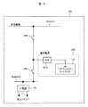
- FIG. 3 shows an example of a power supply system 100 suitable for application to household power supply facilities.
- the power supply system of the present invention configured to include the LIC can be applied to home use.
- the home power supply equipment and the in-house power supply equipment in the general plant (factory or the like) in FIG. There are basic differences. In the case of home use, there is almost no DC load, and in many cases, power is supplied to the AC load. Therefore, the DC power source including the LIC is supplied to the AC load after AC conversion.
- the converter CON is not provided, but the AC power supply bus BUSAC1 and the AC power supply bus BUSAC2 are provided.
- the basic DC power supply equipment is different from the DC battery Bt in that a power conditioner PCS (Power Conditioning System) is provided and the power conditioner PCS is connected to the LIC.
- the power regulator PCS has a mutual conversion function between AC and DC.
- the power supply line BUSAC1 and the power supply line are connected to the AC load by appropriately opening and closing the switches SW6 and SW7. Switching to either or both of the adjusters PCS. At least when AC power is lost, AC power is supplied from the LIC to the AC load via the power regulator PCS.
- FIG. 1 shows the basic configuration of the power supply system 100 of the present invention
- FIG. 2 shows a circuit configuration example when power is supplied to a DC load
- FIG. 3 shows a circuit configuration example when power is supplied to an AC load.
- the present invention can be expected to have an effect of installing a LIC as a new DC power supply facility for any application example of an AC load and a DC load. Next, the operation
- LIC has a high energy density at high output, that is, superior in charge / discharge performance, and long life and safety compared to a conventional storage battery used as DC power supply 200. It has characteristics in terms of performance such as high performance, and it can be expected as an assist power source in a wide range of fields in the future.
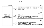
- FIG. 4 is a diagram for explaining how to use the LIC.
- the first use example 201 of the new DC power source (combination of storage battery and LIC) 200 in the power plant shown in FIG. 4 takes advantage of the high output density of the newly installed LIC to supply power immediately after the loss of the AC power source. Is to do. In this scene, the capacity of the storage battery can be reduced by compensating for the discharge current (starting current of plural / single auxiliary machines) generated when the DC power supply facilities are started all at once.
- the first usage example 201 will be described later with reference to FIG.
- the second use example 202 of the new DC power source (combination of storage battery and LIC) 200 shown in FIG. 4 is a power storage method for the storage battery StBt, in addition to the supply from the conventional AC power source, Taking advantage of its excellent charge / discharge performance, supply from LIC is also performed. It may be supplied directly from the LIC as a direct current power source.
- a third usage example 203 of the new DC power source (combination of storage battery and LIC) 200 in the power plant shown in FIG. 4 is a method of storing power for the additionally installed LIC.
- the above use examples are described as typical ones, and it is considered possible to develop them for other purposes.
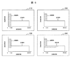
- FIG. 5 shows a concept of performing the first usage example 201 (power supply immediately after the loss of the AC power supply).
- various assist examples are shown that are applied to a power plant and assume a case where power assist is performed when the AC power supply is lost.
- the horizontal axis indicates the time after the loss of AC power
- the vertical axis indicates the DC power amount (load current) required by the DC load.
- the DC power supply 200 can be a facility that can provide the entire amount of the load pattern in FIG. 5, in many cases, the operation is limited to the power supply at the time of startup. For this reason, diesel generators and the like are installed in the power plant, and a DC power source is secured from here.
- the DC power supply (storage battery and LIC) 200 has a function sharing function that covers, for example, a start-up current in a period until the start-up of a diesel generator. In this sense, it is called assist.
- the hatched portions are assist portions by the DC power source (storage battery and LIC) 200.
- power compensation is performed for all of the load current at start-up, for example, for one minute after the loss of AC power.
- power compensation is performed for a part of the load current at start-up, for example, for one minute after the loss of the AC power supply. The degree of compensation is different between case 220 and case 230.
- a part of the steady-state current is compensated together with the compensation of the load current at start-up for one minute after the loss of the AC power supply.
- FIG. 6 is an embodiment showing in detail a specific configuration example of a power supply system for a DC power supply facility in a power plant. In this figure, all configurations necessary for realizing the usage examples 201, 202, and 203 described in FIG. 4 are described.
- the configuration of FIG. 6 basically adopts the configuration of FIG.
- the conventional DC power supply equipment AC power supply bus BUSAC, converter CON, storage battery StBt, DC power supply bus BUSDC, distribution board Bd, switch SW, etc.
- AC power supply bus BUSAC AC power supply bus BUSAC
- converter CON storage battery StBt
- DC power supply bus BUSDC DC power supply bus BUSDC
- distribution board Bd distribution board Bd
- switch SW etc.
- an outdoor electrode plate 314 that stores electric charges by an electric potential in the atmosphere is installed outside the power plant as a capacitor, and is connected to the LIC via the switch SW11.
- a grounded electrode plate 315 and a current detector 316 are installed outside the power plant, and a resistance voltage dividing circuit 312 for adjusting a voltage applied to the LIC in the power plant building and each switch SW for opening and closing a part of the circuit Is installed.
- the additionally installed control unit 330 and power regulator PCS are configured as follows. As described above, in addition to supplying power from the AC power supply bus BUSAC to the storage battery StBt, the charging current stored in the additional LIC is converted from direct current to direct current by the power regulator PCS, and the storage battery StBt Can be supplied. At this time, the power adjuster PCS control unit 332 and the switch control unit 334 provided in the control unit 330 perform opening / closing operations of the switches SW10 and SW5 to control an appropriate amount of power stored in the storage battery StBt.
- Various functions executed under the control of the additionally installed control unit 330 are a power storage function to the LIC, a power storage function to the storage battery, and a power supply function to the load.
- the function of storing power to the LIC includes a case where it is performed from an AC power source and a case where it is performed using an atmospheric electric field, and is implemented with circuit configurations as shown in FIGS.
- the switch SW10 is closed by a close command from the switch control unit 334 in the control unit 330 in a state where the switches SW1 and SW2 are closed, and the PCS control unit
- the power adjuster PCS is controlled by the control signal from 332 to control the amount of electricity stored in the LIC.
- the switch control unit 334 opens the switch SW10 upon completion of power storage. In FIG. 7, switches SW other than those described above remain open. Thereby, power storage Ch1 from the AC power supply to the LIC is executed.
- the switch SW15 is closed by a close command from the switch control unit 334 in the control unit 330, the current is detected by the current detector 316, and the switch control is performed.
- the switches SW11 and SW14 are closed by a closing command from the unit 334.
- the amount of electricity stored in the LIC is controlled by calculating a potential difference generated between the LIC and the outdoor electrode plate 314 in the electrode plate voltage calculation unit 335 and the capacitor voltage measurement unit 333 and changing the resistance value in the resistance voltage dividing circuit 312.
- the switch control unit 334 opens the switches SW11 and SW14 when the power storage is completed. In FIG. 8, switches SW other than those described above remain open. Thereby, power storage Ch2 to the LIC using the atmospheric electric field is executed.
- the above power storage system is caused by changes in the electric field distribution in the atmosphere, but it is a natural phenomenon that always occurs throughout the year, and it is a means of reliably storing power even when AC power is lost.
- the supply amount can be reduced.
- only one LIC is shown, it is assumed that a plurality of LICs are actually connected in parallel, in series, or in series-parallel.
- the storage function to the storage battery includes a case where it is performed from an AC power source and a case where it is performed from a LIC, which are implemented with circuit configurations as shown in FIGS. 9 and 10, respectively.
- the switch SW5 is closed by a close command from the switch control unit 334 in the control unit 330 in a state where the switches SW1 and SW2 are closed.
- the power storage Ch3 is performed to the storage battery StBt. Note that the operation of FIG. 9 has been performed conventionally. Thereby, electricity storage Ch3 from the AC power source to the storage battery StBt is executed.
- the switches SW10, SW5, SW12, and SW13 are closed by the close command from the switch control unit 334 in the control unit 330, and the control signal from the PCS control unit 332 By controlling the power regulator PCS, the amount of power stored in the storage battery StBt is controlled.
- the switch control unit 334 opens the switches SW10, SW5, SW12, and SW13 when the power storage is completed. In FIG. 10, the switches SW other than those described above remain open. Thereby, the storage Ch4 from the LIC to the storage battery StBt is executed.
- the discharge Dch1 from the storage battery StBt to the load is performed by closing the switch SW4 in a state where the switches SW5 and SW3 are closed.
- the switch SW4 is connected to a DC power supply auxiliary machine (for example, an emergency pump) in the power plant, and is automatically closed depending on the process state.
- the switch SW10 is closed by a close command from the switch control unit 334 in the control unit 330 in a state where the switches SW5 and SW3 are closed, and thereafter
- the switch SW5 is opened so that the LIC can be discharged.
- the switch D4 is discharged to the load by closing the switch SW4 in accordance with a closing command from the switch control unit 334 in the control unit 330.
- the PCS control unit 332 controls the PCS, controls the discharge amount from the LIC, and issues a closing command from the switch control unit 334 at the timing set to the rated current value.
- the switch SW5 is closed, and the switch SW10 is switched to discharging from the storage battery by opening with an open command.
- the switch SW10 when the DC power source is used when the AC power source is lost, the switch SW10 is closed by the power regulator PCS control unit 332 and the switch control unit 334 in order to compensate the starting current of the DC auxiliary machine.
- the charging current from the LIC is converted from direct current to direct current by the power regulator PCS, the switches SW3 and SW4 are closed and supplied to each load via the distribution board Bd.
- the switch SW5 on the storage battery StBt side is set to open control, and the opening / closing switching control with the switch SW10 is performed in a state where the auxiliary machine current is settled, thereby suppressing the discharge of the charging current with respect to the starting current from the storage battery StBt. StBt capacity can be reduced.
- FIG. 13 is a diagram corresponding to FIG. 2 of the first embodiment, and is a diagram illustrating an example of a power supply system 100 suitable for application to an in-house power supply facility in a general plant (factory or the like) or a power plant.
- the storage battery StBt is not provided in the DC power supply 200.
- the case where a storage battery is not installed in the in-house power supply facility 200 in the power plant and a new DC power supply 200 is configured only by the LIC is shown.
- FIG. 14 is a diagram corresponding to FIG. 6 of the first embodiment and is a diagram showing in detail a specific configuration example of the power supply system for the DC power supply equipment in the power plant. As apparent from the comparison with FIG. 6, the storage battery StBt and various switches (SW5, SW12, SW13) for charging and discharging the storage battery StBt are deleted.
- the configuration of the system of the second embodiment is such that the DC power source 200 of the first embodiment is a DC power source using only a LIC (lithium ion capacitor). It is possible to operate in the same way of thinking, and it is possible to apply by selecting the capacity according to the load pattern as the DC power supply equipment as in the case of installing the storage battery.
- LIC lithium ion capacitor
- FIG. 15 shows the result of comparison and evaluation of a conventional DC power supply facility composed only of a storage battery and a DC power supply facility in Example 2 in which only the LIC is installed. In this evaluation, examination is performed from the viewpoint of power storage variation, life, and arrangement space.
- this configuration can also be referred to as a position deformation configuration of the second embodiment.
- a position deformation configuration of the second embodiment can also be referred to as a position deformation configuration of the second embodiment.
- an AC load and a DC load at least either configuration is common in that the storage battery StBt is not provided in the DC power supply 200. For this reason, the system configuration and usage in the second embodiment can be applied to FIG. 3 as they are.
- Example 3 shows a case where a new AC power supply 300 is installed as a separate power supply system for the in-house power supply facility 100 in the power plant of Example 2.
- the 16 includes an AC power supply 300 in the on-site power supply facility 100 in the power plant of Example 2 described above.
- the new AC power supply 300 includes the LIC1 and the power regulator PCS1, converts the power of the LIC1 from DC to AC power in the PCS1, and supplies the load to the load via the switch SW20 and the AC power supply bus BUSAC.
- the power source 300 can be used as a power source in the power plant.
- the power storage method for the LIC 1 is the natural phenomenon (atmospheric electric field) described in the first and second embodiments, so that the power can be stored without receiving supply from a conventional AC power source.
- the power plant by providing the DC power supply 200 and the AC power supply 300, the power plant can be operated as shown in FIG. 17 below.
- the monitoring / control 570 of LIC and LIC1 is performed in the central operation room in the power plant, so that the power storage status can be grasped and the power supply 571 to the power plant in a timely manner.
- Example 4 is shown in FIG.
- the DC power supply 200 and the AC power supply 300 are provided as fixed types, but in the fourth embodiment shown in FIG.
- the DC power supply 200 and the AC power supply 300 are fixed power supply facilities installed in the LIC as described in the third embodiment, they are deployed as movable power supplies (DC power supply 200C and AC power supply 300C) by arranging them as cubicles. .
- movable LIC installation type power supply facilities 200C and 300C are obtained.
- the power storage method for the LIC is the power storage by the natural phenomenon (atmospheric electric field) described in the first and second embodiments, and the non-grounded electrode plate 314, the grounded electrode plate 315, and the current detector 316 are installed outside the power plant. . These are installed as necessary switches SW21 to SW24 through the non-grounded electrode plate 314 at necessary locations in the power plant building, and are connected to the movable LIC installation type power supply facilities 200C and 300C by connectors, etc. I do.
- the fourth embodiment it is possible to further disperse as a power supply facility, which is arranged as an individual power source in an auxiliary machine unit or a facility unit in a power plant, so that a power supply system configuration via a conventional transformer or the like This contributes to a reduction in the load.
- the power storage method for LIC is based on natural phenomena (atmospheric electric field), it can be used as an independent power supply facility even in the event of power loss due to system accidents, disasters, etc. It can be expected to be used as an emergency power source.
- a thermal power plant 700 is generally composed of a boiler B / turbine T / generator G, and coal / petroleum / natural as fuel F for generating steam or the like as a driving source thereof.
- the power obtained by the power generation using gas or the like is sent to the transmission line L via the main transformer MTr, while being used as the power source for the power plant as the power source for the power plant via the transformer STr.
- the on-site power source includes an AC power source for AC loads and a power source 100 for DC loads in an emergency.
- the LIC described in the first to fourth embodiments as an assist power source (DC power source 200) for this in-house power source, it is possible to reduce the in-site ratio 716 that accounts for about several percent of the entire power plant. Yes, this means that in the thermal power plant, the fuel input amount 717 is suppressed and the power transmission amount is maintained, that is, the power transmission end efficiency 718 is improved.
- the power storage variation is widened, and it is possible to arrange the battery with long life and space saving.
- the LIC 1 by newly installing the LIC 1 as an AC power source in a fixed type or a movable type, it becomes possible to use it for a distributed power source configuration, an emergency standby power source, or the like.
- FIG. 20 shows a charging mechanism technique for an electric vehicle or the like as an applied technique in a general field where the present invention is developed.
- FIG. 20 shows an electric power supply method according to the development of the present invention.
- electric power generated in the power plant 800 is transmitted to the charging facility 801, and the charging target objects 802 and 803 are charged with electric power.
- the charging facility 801 is an AC power supply bus BUSAC, a converter CON, or the like shown in FIG.
- the charging target object 802 is a conventional factory, power plant, battery in a home power supply system, or the like.
- the charging target object 803 is a moving body such as an automobile.
- the power is not stored in the power plant, but is stored in a natural phenomenon (atmospheric electric field).
- a power supply facility 400 using LIC is configured to form a new charging mechanism.
- FIG. 21 shows an equipment configuration such as a power supply equipment 400 when charging a moving body such as an automobile.
- a power supply facility 400 which is an application example for realizing the fifth embodiment, includes a charging target object 803 and a LIC power source.
- the charging target object 803 substantially retains the configuration of the DC power source 200 illustrated in FIG.
- a storage battery may or may not be included.
- the DC power supply 200 is mounted on the vehicle (object to be charged 803), and charging is performed with the LIC power supply of the charging station.
- the DC power supply 200 in the vehicle is provided with a LIC and a power regulator PCS, and a capacitor voltage controller 331, a power regulator, and a controller 330 necessary for controlling the LIC.
- a PCS control unit 332, a capacitor voltage measurement unit 333, and a switch control unit 334 are installed.
- a resistance voltage dividing circuit 312 that adjusts the voltage applied to the LIC is also installed.
- the outside of these charging target objects 803 is covered with an electrode plate 873 and is a movable object.
- electricity is stored in advance by a power storage system such as a battery or LIC via electric power transmitted from a conventional power plant or natural energy such as a solar panel or wind power. There are no special provisions if the equipment is equipped.
- the charge stored in advance is transferred from the charging facility 877 to the non-grounded electrode plate 874 installed outdoors.
- a current is caused to flow between the grounding side electrode plates 875 installed in. It is possible to control the voltage V0 (V) between the plates on the charging equipment 877 side by checking the value of the current flowing between the plates with the current detector 876 and adjusting the distance between the plates. Become.
- the charging target object 803 covered with the electrode plate 873 moves between the non-grounded electrode plate 874 and the earthed electrode plate 875.
- a voltage V1 (V) is newly generated between the electrode plate 873 and the ground electrode plate 875, and the electric charge moves to the LIC side due to the potential difference, and can be stored as electrostatic energy.
- the charging target object 803 side needs to be grounded by the closed control of the switch SW14 between the non-grounding side electrode plate 873 and the grounding side electrode plate 875. Since there is no need for connection, this is one of the non-contact charging methods.
- FIG. 9 an image 900 of applied technology (non-contact charging) is shown in FIG. This image shows the configuration concept of the charging station 900 using the LIC.
- FIG. 22 imagines a non-contact charging station 900 when the charging target object 803 is a moving body such as an automobile.
- a part of the pillar 901 and the roof 902 which is a basic configuration of the charging station, is assumed to have high electrical conductivity, and the above-described charging equipment 877 and current detector 876 in FIG. 21 are installed therein.
- the charge is moved from the charging facility 877 through the column 901 and the roof 902.
- a non-grounded electrode plate 874 is suspended by a movable wire 909 or the like through the roof 902, and a grounded electrode plate 875 is installed to allow a current to flow between the electrode plates.
- the interelectrode voltage V0a (V), V0b (V) is controlled by the charging facility 877. That is, as the charging station, by making the non-grounded electrode plate 874 movable, it is possible to adjust the distance from the grounded electrode plate 875 through the current detector 876 and change the voltage between the electrode plates. Become.
- a charging target object 803 such as an automobile enters between the non-ground side electrode plate 874 and the ground side electrode plate 875, thereby forming a new electric field E (V / m).
- E electric field
- An object to be charged 803 such as an automobile is grounded 908 and 912 in a state where it is placed between the electrode plates, and an open / close switch or the like between the roof of the vehicle or the like regarded as the electrode plate 873 and the LIC mounted inside the object to be charged 803
- V1a (V), V1b (V) between the charging target object 803 such as an automobile and the non-grounded electrode plate 874
- V1b (V) between the charging target object 803 such as an automobile and the non-grounded electrode plate 874
- It can be stored as electrostatic energy.
- Example 5 the distance between the non-grounded electrode plate 874 and the grounded electrode plate 875 is adjusted on the charging station side so that it is possible to cope with the case where the charging target object 803 such as an automobile is different in shape and charging state. By doing so, it is configured to be more realistic.
- Examples 1 to 5 described in the present invention can be used for various purposes by taking advantage of the ability to repeatedly charge and discharge at high output, which is a feature of LIC.
- the development will proceed with the miniaturization and the storage capacity itself being large, and it will be possible to propose as one of the next generation of natural energy by establishing the storage method using the atmospheric electric field.
- the present invention is not limited to the first to fifth embodiments, and includes various modifications.
- the above-described first embodiment has been described in detail for easy understanding of the present invention, and is not necessarily limited to one having all the configurations described.
- a part of the configuration of one embodiment can be replaced with the configuration of another embodiment, and the configuration of another embodiment can be added to the configuration of one embodiment.
- each of the above-described configurations, functions, processing units, processing means, and the like may be realized by hardware by designing a part or all of them with, for example, an integrated circuit.
- Each of the above-described configurations, functions, and the like may be realized by software by interpreting and executing a program that realizes each function by the processor.
- Information such as programs, tables, and files for realizing each function can be stored in a recording device such as a memory, a hard disk, or an SSD (Solid State Drive), or a recording medium such as an IC card, an SD card, or a DVD.
- control lines and information lines indicate what is considered necessary for the explanation, and not all control lines and information lines are necessarily shown on the product. Actually, it may be considered that almost all the components are connected to each other.
- BUSAC AC power supply bus
- CON converter
- BUSDC DC bus
- Bd distribution board
- Bt DC battery
- StBt storage battery
- LIC lithium ion capacitor
- SW switch
- PCS power regulator
- 334 Switch control unit
Landscapes
- Engineering & Computer Science (AREA)
- Power Engineering (AREA)
- Business, Economics & Management (AREA)
- Emergency Management (AREA)
- Computer Networks & Wireless Communication (AREA)
- Charge And Discharge Circuits For Batteries Or The Like (AREA)
- Stand-By Power Supply Arrangements (AREA)
- Supply And Distribution Of Alternating Current (AREA)
Abstract
LICを新たな直流電源として設けることで、その特性を活かした電源システムおよび充電ステーションを提供する。第1の電源及び直流電源を備えて負荷設備に給電する電源システムであって、直流電源はリチウムイオンキャパシタを含み、リチウムイオンキャパシタからの放電により負荷設備に給電し、リチウムイオンキャパシタを充電するための充電設備は、設置位置と接地点との電位差に伴い電荷を帯電する帯電極板と、帯電極板と電気的に接続し、帯電極板に帯電された電荷を移動させて当該電荷を蓄積するリチウムイオンキャパシタと、帯電極板とリチウムイオンキャパシタとの間に設けるスイッチであって、帯電極板とリチウムイオンキャパシタとの間の電気的な接続を遮断可能に設けるスイッチと、帯電極板の電圧、または、帯電極板に帯電される電荷の量を求める極板電圧算出部と、極板電圧算出部により求められた帯電極板の電圧、または、帯電極板の電荷量に応じてスイッチを開閉制御し、帯電極板に帯電された電荷をリチウムイオンキャパシタへ移動させる制御部と、を有する。
Description
本発明は、直流電源を含む電源システムおよび充電ステーションに係り、特に直流電源としてLIC(リチウムイオンキャパシタ)を含んで構成された電源システムおよび充電ステーションに関する。
電源システムは、各種の多様な産業用設備、家庭用設備、あるいは移動設備などに広く適用され、使用されている。この場合の電源システムは、上記設備内の各種機器(負荷)に対する電源供給システムであって、一般には交流電源(AC)あるいは直流電源(DC)またはその双方で構成されている。さらに電源システムは、無停電電源装置UPS(UPSはここでは両者混成の意味合いがあるが、説明を省略する。)を含んで構成されるものであってもよい。
電源システムが適用される産業用設備の典型的な一例として例えば、発電所用の電源システムがある。発電所における電源システムは、長年に渡る実績により運用が確立された交流電源(AC)と、直流電源(DC)を備えるものが公然共通認識として推移しており、発電所内の各種機器に対して交流または直流の電力を供給している。
具体的に述べると、例えば発電所の発電機の運転においては、それを駆動するタービンがあり、その主機周辺の補機群が適切に運転されていることで、全体としての発電機能を発揮・維持している。ここで発電所は、一般には交流電力の発生システムであるので、一部直流補機と、直流の励磁系統や直流制御系統電源を除いて、殆どが交流(AC)の電源種別である。このように発電所の電源は、通常運転においては交流電源主体に構成されているが、非常時運転のために直流電源を備えるように構成されている。例えば、所内の全交流電源喪失時には、機械系統プロセスの運転許容範囲レベル内での維持のために、例えば、非常用直流電源補機(油ポンプ)を起動して、主機回転体の軸受け損傷を防ぐため給油維持を図るべく、直流電源による非常時想定の構成を採用している。なおこれらの場合において直流電源は、蓄電池を含んで構成されるものがほとんどである。
係る電源構成に関し、高エネルギー密度化と安全性能の向上したリチウムイオンキャパシタLIC(以下単にLICという)を新たな直流電源として設け、発電所内直流負荷への供給及び、吸収を高応答に実行して、負荷への給電支援(アシスト)を実行することが検討されている。
例えば特許文献1には、LICに対する蓄電システム及び蓄電方法として、大気中の電位勾配を利用した静電エネルギーを蓄積する蓄電システム及び蓄電方法に関する技術が記載されている。
前記した発電所電源システムにおいて、蓄電池を含んで構成される直流電源に期待される機能、あるいはこの構成に対する運転仕様の要件は、所内の全交流電源喪失時における緊急かつ必要不可欠な最小限の負荷、機器に対する電力供給である。
具体的には、交流電源断に起因する補機停止と、その結果生ずる油圧低下に対する瞬時の電源供給であり、その応答性上「最速」を期して、蓄電池電源給電の補機(ポンプ)起動の回路を構成した設備としている。この場合に、蓄電設備の負荷の急速立ち上がりのために、補機に大きな始動電流が発生するが、それは蓄電池設備の仕様決定上の制約を付すことになるので、必然であるが合理的ではない。
また蓄電池設備に対する電源供給方法としては、発電所内交流電源を直流電源に変換して行っているが、これは発電によって得られた電力を利用しているのが一般的である。このため、発電所全体としての効率低下を招く結果となっている。
これらの課題に関し、前記した特許文献1に記載のLICに着目すると、蓄電池設備の仕様決定上の制約を受けることがなく、かつ発電所全体としての効率低下を招く恐れがないものと考えられる。
以上のことから本発明では、LICを新たな直流電源として設けることで、その特性を活かした電源システムおよび充電ステーションを提供することを目的としている。
上記課題を解決するために、例えば特許請求の範囲に記載の構成を採用する。本発明は上記課題を解決する手段を複数含んでいるが、その一例を挙げるならば、第1の電源及び直流電源を備えて負荷設備に給電する電源システムであって、直流電源はリチウムイオンキャパシタを含み、リチウムイオンキャパシタからの放電により前記負荷設備に給電することを特徴とする電源システムである。
また本発明は、移動体に搭載され直流電源を備えて負荷に給電する電源システムと、屋外設備で構成された充電ステーションであって、屋外設備として、設置位置と接地点との電位差に伴い電荷を帯電する帯電極板と、帯電極板設置位置と移動体の間の高さ位置を定める高さ調整手段とを備え、直流電源は、帯電極板と電気的に接続し、帯電極板に帯電された電荷を移動させて当該電荷を蓄積するリチウムイオンキャパシタと、帯電極板とリチウムイオンキャパシタとの間に設けるスイッチであって、帯電極板とリチウムイオンキャパシタとの間の電気的な接続を遮断可能に設けるスイッチと、帯電極板の電圧、または、帯電極板に帯電される電荷の量を求める極板電圧算出部と、極板電圧算出部により求められた帯電極板の電圧、または、帯電極板の電荷量に応じてスイッチを開閉制御し、帯電極板に帯電された電荷をリチウムイオンキャパシタへ移動させる制御部と、を有することを特徴とする充電ステーションである。
本発明によれば、LICを新たな直流電源として設けることで、その特性を活かした電源システムおよび充電ステーションを提供することができ、さらに自然エネルギー由来分の寄与でプラント総合効率の向上となる。
具体的な効果は各実施例の中で明らかにするが、例えば直流補機の始動電流に対する補償を維持し、蓄電池容量を低減することが可能であり、さらには応用展開することができる。また、LICへの蓄電方法については、大気中の電位勾配を利用した電荷の蓄積を静電エネルギーとして蓄電するため、他の再生可能エネルギーのような大規模な設備を設置することなく、自然界の一部の苛酷な動的状況変化を一時的に緩和し応用する利用方法となり、環境負荷低減に対する社会的課題の一部の解となるべきものと確信する。
上記した以外の課題、構成及び効果は、以下の実施形態の説明により明らかにされる。
以下、本発明の実施例について図面を用いて詳細に説明する。
本発明は、直流電源を含む電源システムであって、特に直流電源としてLICを含んで構成された電源システムである。本発明の直流電源を含む電源システムは、多様な用途(産業用設備、家庭用設備、あるいは移動設備など)の電源システムとして適用が可能である。またLICの配置、使用法についても各種のものが適用可能である。その為、最初にLICを含んで構成された電源システムの概略構成の一例を説明する。
これらの事例では電源システムを構成する場合、例えば図1に示すように、交流電源母線BUSAC、電力を交流から直流へ変換する変換器CON、直流母線BUSDC、分電盤Bdを介して、図示せぬ直流負荷に直流電力を供給する。また変換器CONの直流側は直流バッテリーBtへ接続されており、直流バッテリーBtに蓄電された直流電力は、直流バッテリーBtから分電盤Bdを介して、必要に応じて所内負荷に電力供給される。
図1の電源構成の場合に、電源システム100自体が図示せぬ直流負荷に直流電力を供給するものであって、広義の意味においては本構成100全体が直流電源といえる。然しながらここでは、交流電源喪失時における直流電力供給を意図しているので、狭義の意味において、つまり交流電源喪失時における電力供給部のことを直流電源200と称している。直流電源200は、直流バッテリーBtを含んで構成され、さらに図1では基本的な直流電源設備である直流バッテリーBtに対してLICを追加設置したものである。なお図1は、本発明の電源システム100の基本構成を開示したものである。従って、この構成を基本として付帯的に各種設備機器を追加設置して、あるいはその一部を削除して電源システム100を構成することが可能である。
図2は、一般プラント(工場等)、あるいは発電所における所内電源設備に適用して好適な電源システム100の例を示している。交流電源母線BUSAC、変換器CON、直流母線BUSDC、分電盤Bdなどを、適宜スイッチSW(SW1からSW5)を介して接続し、図示せぬ直流負荷に直流電力を供給する系統を示している。図1との相違点は、各所に切替用のスイッチが配置されている点、および基本的な直流電源設備として、直流バッテリーBtに替えて蓄電池StBtを配置した点である。基本的な直流電源設備である蓄電池StBtに対してLICを追加設置した点では図1と同じ思想のものである。
図2の構成を一般的な発電所における所内電源設備の構成に適用することを想定すると、通常運転時には、交流電源母線BUSACからスイッチSW1、変換器CON、スイッチSW2、SW5を介して蓄電池StBtへ蓄電している。この状態では他のスイッチSW3、SW4は開放されている。
次に交流電源喪失などの非常時においては、スイッチSW3、SW4を閉じ、スイッチSW1、SW2のいずれか一つを開放する。これにより、発電所内の重要機器(タービン、発電機等)を安全停止させるために設置されている直流電源補機を、分電盤Bdを介して起動させる。係る運転手法は、発電所における長年の経験と実績により構築されたものであり、信頼性の高いシステムとなっている。本発明の実施例では、直流電源設備の供給元として設置している蓄電池StBtにLICを追設し、その組合せによる新たな直流電源200とした場合を示す。
なお図2は、一般プラント(工場等)、あるいは発電所における所内電源設備に適用することを前提としており、これら設備の場合には通常運転時に交流電源により駆動される交流負荷と、交流電源喪失時に直流電源により駆動される直流負荷を含んで構成されている。図2は、このうちの直流電源側100(広義の意味)の設備構成を開示している。従って、交流電源母線BUSACからは、さらに他の交流回路を経由して図示せぬ交流負荷に給電する系統が別途設けられている。
図3は、家庭用における電源設備に適用して好適な電源システム100の例を示している。LICを含んで構成された本発明の電源システムは、家庭用にも適用可能であるが、家庭用の電源設備と、図2の一般プラント(工場等)、あるいは発電所における所内電源設備では、基本的な相違点がある。家庭用の場合には直流負荷を備えることは殆どなく、多くの場合に交流負荷に電力供給している。そのため、LICを含む直流電源は、交流変換後に交流負荷に供給されることになる。
図3の構成を図1の構成と比較すると、変換器CONを備えず、交流電源母線BUSAC1と交流電源母線BUSAC2を備えている。また基本的な直流電源設備として、直流バッテリーBtに替えて電力調整器PCS(Power Conditioning System)を備え、電力調整器PCSをLICに接続している点で相違する。なお電力調整器PCSは、交流と直流の間の相互変換機能を備えている、この構成では、適宜スイッチSW6、SW7を開閉操作して、交流負荷に電力供給するラインを交流電源母線BUSAC1と電力調整器PCSのいずれか、または双方に切り替えている。少なくとも交流電源喪失時には、LICから電力調整器PCSを介して交流負荷に交流電力を供給する。
以上、図1に本発明の電源システム100の基本構成を示し、図2に直流負荷に給電する場合の回路構成事例を示し、図3に交流負荷に給電する場合の回路構成事例を示した。
本発明は、交流負荷、直流負荷の何れの適用例に対しても、新たな直流電源設備として、LICを設置することによる効果が期待できる。次に、図2、図3の回路事例におけるLICを用いた運転について説明する。
本発明は、交流負荷、直流負荷の何れの適用例に対しても、新たな直流電源設備として、LICを設置することによる効果が期待できる。次に、図2、図3の回路事例におけるLICを用いた運転について説明する。
まずLICについて、LICは直流電源200として使用される従来の蓄電池と比較すると、高出力時におけるエネルギー密度が高い、すなわち充放電性能に優れているという機能面での特徴、また、長寿命かつ安全性が高いという性能面での特徴を有しており、今後、幅広い分野におけるアシスト電源として期待が持てるものである。
本発明では、LICによる電力供給を行うことを意図しているが、電力供給の仕方としては、LICの特徴を生かして幾つかの考え方がある。図4は、LICの使用法を説明する図である。
図4に示す、発電所における新たな直流電源(蓄電池とLICの組合せ)200の第1の使用例201は、追設したLICの出力密度が高い特徴を活かし、交流電源喪失直後の電力供給を行うことである。この場面では、直流電源設備が一斉に起動する際に発生する放電電流(複数/単一補機の始動電流)を補償することで、蓄電池の容量を低減させることが可能となる。第1の使用例201について、図5を用いて後述する。
図4に示す、発電所における新たな直流電源(蓄電池とLICの組合せ)200の第2の使用例202は、蓄電池StBtに対する蓄電方法として従来の交流電源からの供給に加え、追設したLICの充放電性能に優れている特徴を活かし、LICからの供給も行うことである。なおLICから直接直流電源として供給することであってもよい。
図4に示す、発電所における新たな直流電源(蓄電池とLICの組合せ)200の第3の使用例203は、追設したLICに対する蓄電方法である。従来の交流電源からの供給に加え、自然現象(大気電界)による蓄電が可能と考えられる。さらには、発電所内における回転体の停止時に発生する回生エネルギー等を利用した蓄電も可能である。これらは、全て交流電源の低減となり、さらには発電所所内動力の低減が期待できる。以上の使用例は代表的なものとして記載しており、その他の用途としても展開することが可能であると考えられる。
図5は、第1の使用例201(交流電源喪失直後の電力供給)を行う考え方を示している。ここでは発電所に適用し、その交流電源喪失時に電力アシストを行う場面を想定した各種のアシスト事例を示している。
図5のアシスト事例210、220、230、240において、横軸には交流電源喪失後の時間、縦軸には直流負荷が必要とする直流電力量(負荷電流)を示している。これらの事例によれば、交流電源喪失後の例えば1分間に大きな始動時負荷電流が流れ、その後例えば60分間程度の期間にはほぼ一定の定常時電流が流れる。これが一般的な直流負荷の負荷パターンである。
直流電源200として、図5の負荷パターンの全量を提供可能な設備とすることが可能であればよいが、多くの場合には起動時の電力供給に限られた運用とされている。このため、発電所にはディーゼル発電機などが設置されて、ここから直流電源が確保されている。直流電源(蓄電池とLIC)200は、例えばディーゼル発電機の起動完了までの期間における始動電流を賄うものとしての機能分担がなされている。この意味においてアシストと称している。図5のアシスト事例210、220、230、240では、斜線で示した部分が直流電源(蓄電池とLIC)200によるアシスト部分である。
事例210では、交流電源喪失後の例えば1分間における始動時負荷電流の全てを電力補償している。事例220と事例230では交流電源喪失後の例えば1分間における始動時負荷電流の一部を電力補償している。補償する一部の程度が事例220と事例230では相違する。事例240では交流電源喪失後の例えば1分間における始動時負荷電流の補償とともに、定常時電流の一部も補償している。
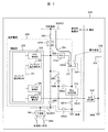
図6は、発電所における直流電源設備に対する電源システムの具体的な構成事例を詳細に示した実施例である。この図には、図4で説明した使用例201、202、203を実現するに必要な全ての構成が記述されている。
図6の構成は、基本的には図2の構成を採用している。そのうえで、発電所建屋内に設置されている従来の直流電源設備(交流電源母線BUSAC、変換器CON、蓄電池StBt、直流電源母線BUSDC、分電盤Bd、スイッチSWなど)に、LICならびにLICへの充放電を制御するために必要となる、制御部330、電力調整器PCSを追設している。
さらに大気電界を利用したLICへの蓄電システムとして、LICをコンデンサとし、大気中の電位によって電荷を蓄電する屋外極板314を発電所屋外に設置し、LICとスイッチSW11を介して接続する。発電所屋外には、さらに接地された極板315と電流検出器316を設置し、発電所建屋内のLICにかかる電圧を調整する抵抗分圧回路312と回路の一部を開閉する各スイッチSWを設置している。
また図6では、追設した制御部330と電力調整器PCSについて、以下のように構成している。前述のように、蓄電池StBtに対しては交流電源母線BUSACからの電力供給に加え、追設したLICに蓄電された充電電流を電力調整器PCSにて直流から直流へ変換し蓄電池StBtに対して供給させることができる。この際、制御部330に設けている電力調整器PCS制御部332、スイッチ制御部334において、スイッチSW10、SW5の開閉操作を行い、蓄電池StBtに対する適切な蓄電量を制御させる。
以下、図6の構成による各種機能とその用法について、さらに詳細な説明を行う。追加設置された制御部330の制御のもとに実行する各種機能は、LICへの蓄電機能、蓄電池への蓄電機能、および負荷への給電機能である。
このうちLICへの蓄電機能は、交流電源から行うケースと、大気電界を用いて行うケースとがあり、それぞれ図7、図8のように回路構成して実施される。
図7に示す交流電源からLICへの蓄電を行うケースでは、スイッチSW1、SW2が閉された状態において、制御部330内のスイッチ制御部334からの閉指令によりスイッチSW10を閉とし、PCS制御部332からの制御信号により電力調整器PCSを制御してLICに対する蓄電量を制御する。スイッチ制御部334は、蓄電完了をもってスイッチSW10を開放する。なお図7において上記説明以外のスイッチSWは開放状態のままとする。これにより、交流電源からLICへの蓄電Ch1が実行される。
図8に示す大気電界を用いてLICへの蓄電を行うケースでは、制御部330内のスイッチ制御部334からの閉指令によりスイッチSW15を閉とし、電流検出器316において電流を検出し、スイッチ制御部334からの閉指令によりスイッチSW11、SW14を閉とする。LICに対する蓄電量は、極板電圧算出部335とコンデンサ電圧測定部333においてLICと屋外極板314間に発生する電位差を算出し、抵抗分圧回路312において抵抗値を変化させることで制御する。スイッチ制御部334は、蓄電完了をもってスイッチSW11、SW14を開放する。なお図8において上記説明以外のスイッチSWは開放状態のままとする。これにより、大気電界を用いるLICへの蓄電Ch2が実行される。
ここで、大気電界を用いたLICへの蓄電については、先述の特許文献1に詳述されているが、ここで簡単に説明をしておく。蓄電方法の原理は特許文献1の記述によるが、要するに大気中の電界分布に応じた電荷が屋外極板314に蓄積され、接地側極板315との間に流れる電流値を電流検出器316にて検出し、制御部330に設置したコンデンサ電圧測定部333ならびに、極板電圧算出部335よりLICの端子間にかかる電圧を算出し、屋外の極板間314、315との間に生じる電位差によりスイッチSW11を閉制御とし、LIC側へ電流を流すことで蓄電させたものである。この際、LICには許容電圧があるため、その許容電圧の範囲内に収まるよう、抵抗分圧回路312を設置し、抵抗値を変化させることでLICにかかる電圧を分圧させている。
上記の蓄電システムは大気中の電界分布の変化により起こるものであるが、年間を通じて必ず発生する自然現象であり、交流電源喪失時においても確実に蓄電する一つの手段であることから、交流電源の供給量の低減が可能となる。ここで、LICは1つのみ示しているが、実際には複数のLICが並列、直列または直並列に接続されるものとする。
次に蓄電池への蓄電機能について説明する。蓄電池への蓄電機能には、交流電源から行うケースと、LICから行うケースとがあり、それぞれ図9、図10のように回路構成して実施される。
図9に示す交流電源から蓄電池StBtへの蓄電を行うケースでは、スイッチSW1、SW2が閉された状態において、制御部330内のスイッチ制御部334からの閉指令によりスイッチSW5を閉とすることで蓄電池StBtへの蓄電Ch3を行う。なお図9の操作は従来から行われていたものである。これにより、交流電源から蓄電池StBtへの蓄電Ch3が実行される。
図10に示すLICから蓄電池StBtへの蓄電を行うケースでは、制御部330内のスイッチ制御部334からの閉指令によりスイッチSW10、SW5、SW12、SW13を閉とし、PCS制御部332からの制御信号により電力調整器PCSを制御して蓄電池StBtに対する蓄電量を制御する。スイッチ制御部334は、蓄電完了をもってスイッチSW10、SW5、SW12、SW13を開放する。なお図10において上記説明以外のスイッチSWは開放状態のままとする。これにより、LICから蓄電池StBtへの蓄電Ch4が実行される。
最後に、負荷への給電機能について説明する。負荷への給電は蓄電池StBtから行うケースと、LICから行うケースと、双方により行うケースがあるが、ここでは蓄電池StBtから行うケースと、双方により行うケースについて、図11、図12を用いて説明する。
図11に示す蓄電池StBtから負荷への給電を行うケースでは、スイッチSW5、SW3が閉された状態において、スイッチSW4を閉することで、蓄電池StBtから負荷に対する放電Dch1を行う。スイッチSW4の接続先については、発電所における直流電源補機(例えば非常用ポンプなど)が対象であり、プロセス状態により自動的に閉じられる。
図12に示す蓄電池StBtとLICから負荷への給電を行うケースでは、スイッチSW5、SW3が閉された状態において、制御部330内のスイッチ制御部334からの閉指令によりスイッチSW10を閉とし、その後スイッチ制御部334からの開指令によりスイッチSW5を開放させ、LICからの放電が可能な状態とする。この場合に、制御部330内のスイッチ制御部334からの閉指令によりスイッチSW4を閉することで、負荷に対する放電Dch2を行う。なお直流電源補機に対する指導電流を補償すべく、PCS制御部332にてPCSを制御し、LICからの放電量をコントロールし、定格電流値へ整定したタイミングでスイッチ制御部334からの閉指令にてスイッチSW5を閉とし、スイッチSW10に対しては開指令にて開することで蓄電池からの放電に切り替える。
上記説明によれば、交流電源喪失時における直流電源使用時においては、直流補機の始動電流を補償するため、電力調整器PCS制御部332、スイッチ制御部334にてスイッチSW10を閉制御してLICからの充電電流を電力調整器PCSにて直流から直流へ変換し、スイッチSW3、SW4を閉制御し、分電盤Bdを介して各負荷へ供給する。この際、蓄電池StBt側のスイッチSW5は開制御とし、補機電流が整定した状態にてスイッチSW10との開閉切り替え制御を行うことで、蓄電池StBtからの始動電流に対する充電電流の放出を抑え、蓄電池StBt容量低減を可能とする。
以上のように本実施例では、LICを電力調整器PCSにて適切に制御することにより、特徴の1つである高出力での充放電を可能とし、また大気電界による蓄電システムを適用することにより自然エネルギーを利用した蓄電も可能となることから、従来の蓄電池のみとしている直流電源設備をより安定かつ、信頼性の高いシステムとすることが可能となる。
実施例1では、直流電源200内に蓄電池StBtを備えることを前提に説明を行ったが、本発明の適用事例としては必ずしも蓄電池StBtを必要としてはいない。このことから実施例2においては、本発明の応用展開として、直流電源200内に蓄電池StBtを備えず、LICから放電を行う場合の事例について、図13、図14を用いて説明する。
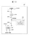
図13は、実施例1の図2に対応する図であり、一般プラント(工場等)、発電所における所内電源設備に適用して好適な電源システム100の例を示す図である。図2と比較して明らかなように、直流電源200内に蓄電池StBtを備えていない点でのみ相違している。発電所における所内電源設備200に対して、蓄電池を非設置とし、LICのみで新たな直流電源200を構成させた場合を示している。
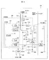
図14は、実施例1の図6に対応する図であり、発電所における直流電源設備に対する電源システムの具体的な構成事例を詳細に示した図である。図6と比較して明らかなように、蓄電池StBt、および蓄電池StBtの充放電を行うための各種スイッチ類(SW5、SW12、SW13)が削除されている。
実施例2のシステムの構成は、実施例1の直流電源200がLIC(リチウムイオンキャパシタ)のみでの直流電源となるが、直流電源としての供給方法、LICに対する蓄電方法については、実施例1と同様の考え方での運用が可能であり、蓄電池設置時と同様に直流電源設備としての負荷パターンに応じた容量選定を行うことで、適用が可能である。
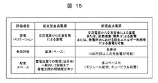
次に、蓄電池のみで構成された従来型の直流電源設備と、LICのみを設置した実施例2の場合の直流電源設備を比較、評価した結果を図15に示す。この評価では、蓄電バリエーション、寿命、配置スペースの観点から検討している。
まず蓄電バリエーションの観点での比較について、LICでは、その特徴を活かすことにより、交流電源からの交直変換による蓄電に加え、自然現象(大気電界)による蓄電または、発電所内における回転体の停止時に発生する回生エネルギー等の利用による蓄電も可能と考えられ、蓄電池よりもメリットは高いものと考えられる。
また、寿命評価の面からも、一般的なLICにおける充放電回数(100万回以上)を考えると、その使用目的は蓄電池と比較としても様々な用途に展開することが可能であり、配置スペースとしても、蓄電池と比較し、その安全性の高さからモジュール配列、あるいはキュービクル配列が可能であり、現状の蓄電池室に対して省スペース化も可能となることが期待できる。
なお、図3に示した家庭用における電源設備に適用して好適な電源システム100の例に関し、この構成もまた実施例2の位置変形構成ということができる。交流負荷と直流負荷の相違はあるが、少なくともいずれの構成においても直流電源200内に蓄電池StBtを備えていない点で共通している。このため、実施例2におけるシステム構成、使用法などがそのままに図3に適用可能である。
実施例3では、実施例2の発電所における所内電源設備100に対して、さらに別電源系統として新たな交流電源300を設置した場合を示している。
図16の実施例3の構成では、前述した実施例2の発電所における所内電源設備100内に交流電源300を含む。新たな交流電源300は、LIC1と電力調整器PCS1を備え、LIC1の電力をPCS1において直流から交流電源に変換し、スイッチSW20、交流電源母線BUSACを介して負荷に給電することで、新たな交流電源300として発電所所内電源としての利用が可能となる。また、LIC1に対する蓄電方法は実施例1、実施例2で説明した自然現象(大気電界)等とすることで、従来の交流電源からの供給を受けることなく蓄電が可能である。
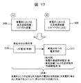
また実施例3の電源構成によれば、直流電源200と交流電源300を備えたことにより、当該発電所の運営を以下の図17のように行うことができる。図17によれば、発電所内の中央操作室にてLIC、LIC1の監視/制御570を行わせることにより、蓄電状況を把握し、適時発電所内への電源供給571が可能となる。これは、設置されるLIC、LIC1の容量によるが、発電所としては、定常的に使用量が把握できる建屋内照明電源等、さらには発電設備における定例操作用の各補機電源等についても使用量を把握することが可能であるため、新たな交流電源300からの供給が可能である。これは、発電所として必要な所内負荷の電源を自然現象(大気電界)等により供給するため、見かけ上のロス低減になる。
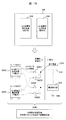
次に、LICの更なる応用展開として、図18に実施例4を示す。実施例3では、直流電源200と交流電源300を固定型として備えることを想定していたが、図18に示す実施例4では可搬型としている。実施例3において説明した、LICを設置した直流電源200、交流電源300固定式の電源設備としているが、キュービクルとして配列することにより、可動式の電源(直流電源200C、交流電源300C)として展開する。キュービクルタイプとして配列したLICに例えば滑車のようなものを設置することで、可動式のLIC設置型電源設備200C、300Cとする。
一方、LICに対する蓄電方法は実施例1、実施例2において説明した自然現象(大気電界)による蓄電とし、発電所屋外に非接地極板314と接地極板315、ならびに電流検出器316を設置する。これらは、非接地極板314を通して、発電所建屋内の必要箇所に各スイッチSW21~SW24として設置され、可動式のLIC設置型電源設備200C、300Cとコネクター等にて接続させることにより、適時蓄電を行う。
実施例4によれば、電源設備としてより分散させることが可能であり、それは発電所内における補機単位あるいは、設備単位に個別電源として配置させることで、従来の変圧器等を介した電源系統構成に対する負荷低減へ寄与するものとなる。また、LICへの蓄電方法を自然現象(大気電界)によるものとしていることから、系統事故、災害等による電源喪失時においても独立した電源設備として使用することが可能であり、非常時においては発電所の緊急電源として活用することが期待できる。
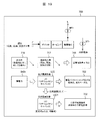
以上、発電所における直流電源設備に対してLICを追設した場合を実施例1~4として説明したが、これを火力発電所において適用した場合の効果を、図19を用いて説明する。
図19に示すように火力発電所700は、一般的にボイラーB/タービンT/発電機Gにより構成されており、その駆動源となる蒸気等を発生させるための燃料Fとして石炭/石油/天然ガス等を使用し、その発電によって得られた電力は、主変圧器MTrを介して送電線Lに送られる一方、発電所内用の電力として、所内変圧器STrを介して所内電源として使用している。所内電源は、交流負荷用の交流電源と、非常時の直流負荷用の電源100を含んで構成されている。
この所内電源に対して、実施例1~4にて説明したLICをアシスト電源(直流電源200)として設置することで、発電所全体の約数%を占める所内率716を低減させることが可能であり、それは火力発電所においては燃料投入量717を抑え送電量を維持する、すなわち送電端効率718を向上させることを意味している。
また、従来の直流電源設備として使用していた蓄電池StBtをLICに転換することにより、その効果722としては、蓄電バリエーションが広がり、長寿命かつ省スペースに配置が可能となる。さらなる効果732としては、LIC1を交流電源として、固定式または可動式に新たに設置することにより、分散型の電源構成、非常時の予備電源等に使用することが可能となる。
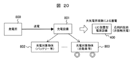
次に、本発明を展開した一般的分野における応用的技術として、電気自動車等に対する充電機構技術について図20に示す。
図20は、本発明の展開による電力供給手法を示したものであり、従来は発電所800で発生した電力を充電設備801に送電し、充電対象物体802、803に電力を充電している。この場合に、充電設備801とは、図1などの交流電源母線BUSAC、変換器CONなどである。また充電対象物体802は、旧来の工場、発電所、家庭内の電源システム内のバッテリーなどである。
これに対し本発明の実施例5の展開によれば、充電対象物体803は自動車などの移動体である。また電力は、発電所において発生した電力ではなく、自然現象(大気電界)による蓄電を志向している。
つまり、現在、バッテリー、自動車等の充電対象物体802、803に対して充電する場合、各発電所800から送電された電力を各充電設備801に蓄え、充電対象物体802に対して供給しているのが、一般的である。ここでは、自然現象(大気電界)による蓄電方法の応用的技術として、LICを用いた電源設備400を構成することで、新たな充電機構としている。
図21は、自動車などの移動体に充電する場合の電源設備400などの設備構成を示している。実施例5を実現するための適用例である電源設備400は、充電対象物体803とLIC電源で構成されている。この場合に、充電対象物体803は、図6に例示する直流電源200の構成をほぼそのまま保有する。この場合に、蓄電池を含んでも含まなくともよい。要するに車両(充電対象物体803)に直流電源200を搭載し、充電ステーションのLIC電源で充電するという使用法になる。
車両(充電対象物体803)内の直流電源200には、LICならびに、電力調整器PCSを設置し、さらに、LICを制御するために必要となる制御部330にコンデンサ電圧制御部331、電力調整器PCS制御部332、コンデンサ電圧測定部333、スイッチ制御部334を設置する。また、LICにかかる電圧を調整する抵抗分圧回路312についても設置する。これらの充電対象物体803の外側は極板873にて覆われている状態とし、移動が可能な物体とする。これに対して充電設備877側については、従来技術である発電所から送電された電力あるいは、太陽光パネル、風力等の自然エネルギー等を介して、バッテリーやLIC等の蓄電システムによりあらかじめ電気を蓄電している設備であれば特に規定はされない。
次に車両(充電対象物体803)内の直流電源200に対する充電の方法としては、充電設備877から、屋外に設置した非接地側極板874にあらかじめ蓄電された電荷を移動させることで、同じく屋外に設置した接地側極板875の間に電流を流す。この極板間に流れる電流値を電流検出器876にて確認し、極板間の距離を調整することで、極板間電圧V0(V)を充電設備877側にてコントロールすることが可能となる。
この状態は、ある程度コントロールされた電界を構成している状態となるため、非接地側極板874と接地側極板875の間に極板873にて覆われた充電対象物体803が移動してくることにより、新たに極板873と接地側極板875の間に電圧V1(V)が発生し、その電位差によりLIC側に電荷が移動し、静電エネルギーとして蓄電することが可能である。この際、充電対象物体803側については、非接地側極板873と接地側極板875の間でスイッチSW14の閉制御により接地する必要はあるが、従来のように充電設備からのプラグ等による接続の必要はないことから、非接触による充電方式の一つである。
実施例5の実運用例として、図22に応用的技術(非接触充電)のイメージ900を示している。このイメージは、LICを用いた充電ステーション900の構成概念を示している。
図22は、充電対象物体803が自動車等の移動体とした場合の非接触による充電ステーション900をイメージしている。その構成としては、充電ステーションの基本構成となる、柱901、屋根902について、その一部は通電性の高いものとし、そこに前述した図21の充電設備877ならびに電流検出器876を設置する。ここで図21における説明と同様に、ある程度コントロールされた電界を構成する必要があるため、充電設備877より柱901、屋根902を通じて電荷を移動させる。
そこに屋根902を通じて非接地側極板874を可動式ワイヤ909などで吊り、接地側極板875を設置することで極板間に電流が流れ、図21における説明と同様に、極板間の距離を調整することで、極板間電圧V0a(V)、V0b(V)を充電設備877でコントロールさせる。すなわち、充電ステーションとしては、非接地側極板874を可動式とすることで、電流検出器876を通じて、接地側極板875との距離を調整し、極板間電圧を変化させることが可能となる。
ここに、自動車等の充電対象物体803が、非接地側極板874と接地側極板875の間に入ることで、新たな電界E(V/m)を形成させる。これは、自動車等の充電対象物体803内にLIC他の設備を搭載し、極板873に関しては自動等の屋根と見立てれば、実現可能と考える。自動車等の充電対象物体803は極板間に入った状態で、接地908、912させ、極板873と見立てた自動車等の屋根と充電対象物体803内部に搭載しているLIC間を開閉スイッチ等にて接続することで、自動車等の充電対象物体803と非接地側極板874との間に電圧V1a(V)、V1b(V)が発生し、その電位差によりLIC側に電荷が移動し、静電エネルギーとして蓄電することが可能である。
実施例5では、自動車等の充電対象物体803が形状、充電状態が異なる場合においても対応可能となるよう、非接地側極板874と接地側極板875間の距離を充電ステーション側にて調整することで、より現実的に対応可能となる構成としている。
以上、本発明にて説明した実施例1~5については、何れもLICの特徴である、高出力での充放電が繰り返し可能であることを活かすことにより、様々な用途として使用可能であることを示しおり、今後より小型化し、蓄電容量自体が大容量なものとして開発が進み、また、大気電界による蓄電方法が確立されることにより、次世代の自然エネルギーの一つとして提案可能と考える。
なお、本発明は実施例1~5に限定されるものではなく、様々な変形例が含まれる。例えば、上記した実施例1は本発明を分かりやすく説明するために詳細に説明したものであり、必ずしも説明した全ての構成を備えるものに限定されるものでもない。また、ある実施例の構成の一部を他の実施例の構成に置き換えることが可能であり、また、ある実施例の構成に他の実施例の構成を加えることも可能である。また、各実施例の構成の一部について、他の構成の追加・削除・置換をすることが可能である。
また、上記の各構成、機能、処理部、処理手段等は、それらの一部または全部を、例えば、集積回路で設計する等によりハードウェアで実現してもよい。また、上記の各構成、機能等は、プロセッサがそれぞれの機能を実現するプログラムを解釈し、実行することによりソフトウェアで実現してもよい。各機能を実現するプログラム、テーブル、ファイル等の情報は、メモリやハードディスク、SSD(Solid State Drive)等の記録装置、または、ICカード、SDカード、DVD等の記録媒体に置くことができる。
また、制御線や情報線は、説明上必要と考えられるものを示しており、製品上、必ずしも全ての制御線や情報線を示しているとは限らない。実際には殆ど全ての構成が相互に接続されていると考えてもよい。
BUSAC:交流電源母線,CON:変換器,BUSDC:直流母線,Bd:分電盤,Bt:直流バッテリー,StBt:蓄電池,LIC:リチウムイオンキャパシタ,SW:スイッチ,PCS: 電力調整器,100:電源システム,200:直流電源,312:抵抗分圧回路,314:屋外極板,315:極板,316:電流検出器,330:制御部,332:電力調整器PCS制御部,334:スイッチ制御部
Claims (11)
- 第1の電源及び直流電源を備えて負荷設備に給電する電源システムであって、
前記直流電源はリチウムイオンキャパシタを含み、リチウムイオンキャパシタからの放電により前記負荷設備に給電することを特徴とする電源システム。 - 請求項1に記載の電源システムであって、
前記第1の電源は交流電源であって、前記直流電源は前記第1の電源の喪失時に、リチウムイオンキャパシタからの放電により前記負荷設備に給電することを特徴とする電源システム。 - 請求項1または請求項2に記載の電源システムであって、
前記リチウムイオンキャパシタを充電するための充電設備は、
設置位置と接地点との電位差に伴い電荷を帯電する帯電極板と、前記帯電極板と電気的に接続し、前記帯電極板に帯電された電荷を移動させて当該電荷を蓄積する前記リチウムイオンキャパシタと、前記帯電極板と前記リチウムイオンキャパシタとの間に設けるスイッチであって、前記帯電極板と前記リチウムイオンキャパシタとの間の電気的な接続を遮断可能に設けるスイッチと、前記帯電極板の電圧、または、前記帯電極板に帯電される電荷の量を求める極板電圧算出部と、前記極板電圧算出部により求められた前記帯電極板の電圧、または、前記帯電極板の電荷量に応じて前記スイッチを開閉制御し、前記帯電極板に帯電された電荷を前記リチウムイオンキャパシタへ移動させる制御部と、を有することを特徴とする電源システム。 - 請求項3に記載の電源システムであって、
前記直流電源は蓄電池を含み、該蓄電池は前記第1の電源から充電され、前記リチウムイオンキャパシタは前記充電設備により充電され、前記第1の電源の喪失時に、前記蓄電池及び、前記リチウムイオンキャパシタからの放電により前記負荷設備に給電することを特徴とする電源システム。 - 請求項1から請求項4のいずれか1項に記載の電源システムであって、
前記第1の電源は交流電源であって、交流電源の一部に第2のリチウムイオンキャパシタを含み、該第2のリチウムイオンキャパシタを充電するための充電設備は、
設置位置と接地点との電位差に伴い電荷を帯電する帯電極板と、前記帯電極板と電気的に接続し、前記帯電極板に帯電された電荷を移動させて当該電荷を蓄積する前記第2のリチウムイオンキャパシタと、前記帯電極板と前記第2のリチウムイオンキャパシタとの間に設けるスイッチであって、前記帯電極板と前記第2のリチウムイオンキャパシタとの間の電気的な接続を遮断可能に設けるスイッチと、前記帯電極板の電圧、または、前記帯電極板に帯電される電荷の量を求める極板電圧算出部と、前記極板電圧算出部により求められた前記帯電極板の電圧、または、前記帯電極板の電荷量に応じて前記スイッチを開閉制御し、前記帯電極板に帯電された電荷を前記第2のリチウムイオンキャパシタへ移動させる制御部と、前記第2のリチウムイオンキャパシタの電力を直流から交流に変換して前記交流電源に接続する電力変換手段、を有することを特徴とする電源システム。 - 請求項1から請求項5のいずれか1項に記載の電源システムであって、
前記直流電源は、可動可能に構成されていることを特徴とする電源システム。 - 請求項1から請求項6のいずれか1項に記載の電源システムであって、
電源システムは、一般プラント(工場等)、あるいは発電所における所内電源設備における非常用電源として使用されることを特徴とする電源システム。 - 移動体に搭載され、直流電源を備えて負荷に給電する電源システムであって、
前記直流電源はリチウムイオンキャパシタを含み、リチウムイオンキャパシタからの放電により前記負荷に給電することを特徴とする電源システム。 - 請求項8に記載の、移動体に搭載された電源システムであって、
前記直流電源は、外部の帯電極板と電気的に接続し、前記帯電極板に帯電された電荷を移動させて当該電荷を蓄積する前記リチウムイオンキャパシタと、前記帯電極板と前記リチウムイオンキャパシタとの間に設けるスイッチであって、前記帯電極板と前記リチウムイオンキャパシタとの間の電気的な接続を遮断可能に設けるスイッチと、前記帯電極板の電圧、または、前記帯電極板に帯電される電荷の量を求める極板電圧算出部と、前記極板電圧算出部により求められた前記帯電極板の電圧、または、前記帯電極板の電荷量に応じて前記スイッチを開閉制御し、前記帯電極板に帯電された電荷を前記リチウムイオンキャパシタへ移動させる制御部と、を有することを特徴とする電源システム。 - 移動体に搭載され直流電源を備えて負荷に給電する電源システムと、屋外設備で構成された充電ステーションであって、
屋外設備として、設置位置と接地点との電位差に伴い電荷を帯電する帯電極板と、該帯電極板設置位置と前記移動体の間の高さ位置を定める高さ調整手段とを備え、
前記直流電源は、前記帯電極板と電気的に接続し、前記帯電極板に帯電された電荷を移動させて当該電荷を蓄積する前記リチウムイオンキャパシタと、前記帯電極板と前記リチウムイオンキャパシタとの間に設けるスイッチであって、前記帯電極板と前記リチウムイオンキャパシタとの間の電気的な接続を遮断可能に設けるスイッチと、前記帯電極板の電圧、または、前記帯電極板に帯電される電荷の量を求める極板電圧算出部と、前記極板電圧算出部により求められた前記帯電極板の電圧、または、前記帯電極板の電荷量に応じて前記スイッチを開閉制御し、前記帯電極板に帯電された電荷を前記リチウムイオンキャパシタへ移動させる制御部と、を有することを特徴とする充電ステーション。 - 請求項10に記載の充電ステーションであって、
前記帯電電極により屋根を構成し、当該屋根下に誘導した前記移動体胴体への電荷の移動により、屋根の前記帯電電極である非接地側極板と、接地側極板間に強制的に電界を形成し、極板間に発生する電位差による電荷の移動により蓄電させるとともに、屋根から前記移動体胴体までの高さ位置調整により電界を調整することを特徴とする充電ステーション。
Applications Claiming Priority (2)
| Application Number | Priority Date | Filing Date | Title |
|---|---|---|---|
| JP2015-123514 | 2015-06-19 | ||
| JP2015123514A JP2018129867A (ja) | 2015-06-19 | 2015-06-19 | 電源システムおよび充電ステーション |
Publications (1)
| Publication Number | Publication Date |
|---|---|
| WO2016203995A1 true WO2016203995A1 (ja) | 2016-12-22 |
Family
ID=57545236
Family Applications (1)
| Application Number | Title | Priority Date | Filing Date |
|---|---|---|---|
| PCT/JP2016/066581 Ceased WO2016203995A1 (ja) | 2015-06-19 | 2016-06-03 | 電源システムおよび充電ステーション |
Country Status (2)
| Country | Link |
|---|---|
| JP (1) | JP2018129867A (ja) |
| WO (1) | WO2016203995A1 (ja) |
Families Citing this family (1)
| Publication number | Priority date | Publication date | Assignee | Title |
|---|---|---|---|---|
| JP7419451B1 (ja) | 2022-07-26 | 2024-01-22 | 東芝プラントシステム株式会社 | 電源装置 |
Citations (3)
| Publication number | Priority date | Publication date | Assignee | Title |
|---|---|---|---|---|
| JP2013132182A (ja) * | 2011-12-22 | 2013-07-04 | Rohm Co Ltd | 電力制御システムおよび電力制御方法 |
| WO2013145002A1 (ja) * | 2012-03-28 | 2013-10-03 | 株式会社 日立製作所 | 蓄電システム及び蓄電方法 |
| JP2015012751A (ja) * | 2013-07-01 | 2015-01-19 | 星和電機株式会社 | 蓄電装置 |
-
2015
- 2015-06-19 JP JP2015123514A patent/JP2018129867A/ja active Pending
-
2016
- 2016-06-03 WO PCT/JP2016/066581 patent/WO2016203995A1/ja not_active Ceased
Patent Citations (3)
| Publication number | Priority date | Publication date | Assignee | Title |
|---|---|---|---|---|
| JP2013132182A (ja) * | 2011-12-22 | 2013-07-04 | Rohm Co Ltd | 電力制御システムおよび電力制御方法 |
| WO2013145002A1 (ja) * | 2012-03-28 | 2013-10-03 | 株式会社 日立製作所 | 蓄電システム及び蓄電方法 |
| JP2015012751A (ja) * | 2013-07-01 | 2015-01-19 | 星和電機株式会社 | 蓄電装置 |
Also Published As
| Publication number | Publication date |
|---|---|
| JP2018129867A (ja) | 2018-08-16 |
Similar Documents
| Publication | Publication Date | Title |
|---|---|---|
| JP6050757B2 (ja) | 直流マイクログリッド機能を備えた自立運転可能な燃料電池システム | |
| US10873099B1 (en) | Storage system controller | |
| ES2665979T3 (es) | Sistema de ascensor con un dispositivo de almacenamiento de energía | |
| US20200389043A1 (en) | Fuel cell system for information technology loads | |
| CN112550072B (zh) | 用于电驱动车辆的能量系统 | |
| WO2014132321A1 (ja) | 電源装置 | |
| SG186432A1 (en) | Energy storage system | |
| KR101699135B1 (ko) | 독립형 마이크로그리드 시스템 | |
| CN106487097A (zh) | 用于交流电压网的蓄能装置 | |
| JP2013126343A (ja) | 蓄電デバイスを備えた電力蓄積システム | |
| KR20240009554A (ko) | 전력계통 연계 에너지저장장치기반 전기차 충전스테이션 | |
| KR101437349B1 (ko) | 다기능 에너지저장장치 기반의 철도연계형 전기자동차 충전전력 시스템 | |
| JP2020508030A (ja) | 補助電力供給部を備えた風力タービン | |
| ITPI20110142A1 (it) | Apparato di trasformazione di energia prodotta da fonti rinnovabili e metodo di gestione relativo | |
| JP6089565B2 (ja) | 非常用電源システム | |
| CN219145028U (zh) | 一种储能汇流升压接入系统 | |
| CN103187745A (zh) | 风电机组自用电系统、风力发电机及其自用电供电方法 | |
| JP6977167B2 (ja) | エネルギー貯蔵システム | |
| KR102257906B1 (ko) | 에너지 저장 시스템 | |
| JP2018129867A (ja) | 電源システムおよび充電ステーション | |
| CN111555167B (zh) | 箱式变电站及光伏发电系统 | |
| KR20180069406A (ko) | 수퍼캐패시터 충.방전 제어장치 | |
| WO2016033769A1 (en) | Method and system for coordinating control of wind farm during disconnection to utility grid | |
| Borisov et al. | Charging Station Infrastructure and Standards for Electric Vehicles-State, Problems and Future Trends | |
| JP6752467B1 (ja) | 直流電源供給装置 |
Legal Events
| Date | Code | Title | Description |
|---|---|---|---|
| 121 | Ep: the epo has been informed by wipo that ep was designated in this application |
Ref document number: 16811470 Country of ref document: EP Kind code of ref document: A1 |
|
| NENP | Non-entry into the national phase |
Ref country code: DE |
|
| 122 | Ep: pct application non-entry in european phase |
Ref document number: 16811470 Country of ref document: EP Kind code of ref document: A1 |
|
| NENP | Non-entry into the national phase |
Ref country code: JP |